CN109079552B - Triaxial cutter servo device based on compliant parallel mechanism - Google Patents
Triaxial cutter servo device based on compliant parallel mechanism Download PDFInfo
- Publication number
- CN109079552B CN109079552B CN201810931177.1A CN201810931177A CN109079552B CN 109079552 B CN109079552 B CN 109079552B CN 201810931177 A CN201810931177 A CN 201810931177A CN 109079552 B CN109079552 B CN 109079552B
- Authority
- CN
- China
- Prior art keywords
- axis
- end effector
- outer side
- triaxial
- compliant
- Prior art date
- Legal status (The legal status is an assumption and is not a legal conclusion. Google has not performed a legal analysis and makes no representation as to the accuracy of the status listed.)
- Active
Links
Images



Classifications
-
- B—PERFORMING OPERATIONS; TRANSPORTING
- B23—MACHINE TOOLS; METAL-WORKING NOT OTHERWISE PROVIDED FOR
- B23Q—DETAILS, COMPONENTS, OR ACCESSORIES FOR MACHINE TOOLS, e.g. ARRANGEMENTS FOR COPYING OR CONTROLLING; MACHINE TOOLS IN GENERAL CHARACTERISED BY THE CONSTRUCTION OF PARTICULAR DETAILS OR COMPONENTS; COMBINATIONS OR ASSOCIATIONS OF METAL-WORKING MACHINES, NOT DIRECTED TO A PARTICULAR RESULT
- B23Q5/00—Driving or feeding mechanisms; Control arrangements therefor
- B23Q5/22—Feeding members carrying tools or work
- B23Q5/28—Electric drives
Landscapes
- Engineering & Computer Science (AREA)
- Mechanical Engineering (AREA)
- Manipulator (AREA)
- Force Measurement Appropriate To Specific Purposes (AREA)
Abstract
Description
技术领域technical field
本发明涉及纳米定位、测量与加工装置的技术领域,更具体地,涉及一种基于柔顺并联机构的三轴刀具伺服装置。The invention relates to the technical field of nano-positioning, measuring and processing devices, and more particularly, to a three-axis tool servo device based on a compliant parallel mechanism.
背景技术Background technique
柔顺机构是构成纳米定位、测量与加工装置机构本体的主要手段之一,是微纳操作、微纳测量以及微纳加工/制造等技术的关键部分,在超精密加工、精密工程及微机电系统等相关领域中发挥着重要的作用。The compliance mechanism is one of the main means of forming the body of the nano-positioning, measuring and processing device. It is a key part of micro-nano operation, micro-nano measurement, and micro-nano processing/manufacturing. plays an important role in related fields.
柔顺铰链利用结构中薄弱部分易于变形的特点和材料自身的可逆性弹性变形特性来实现所要求的运动副功能,具有免装配、零间隙、无摩擦及免润滑等优点。柔顺机构将机构各运动支链的运动副以柔顺铰链代替,用柔性连杆将各个柔顺铰链连接在一起形成相对应的柔性支链,通过柔顺铰链将运动平台和固定基座相连接从而构成相应的机构。通过刚体替换法设计的柔顺机构可实现所要求的运动与功能,但在一些具有更高精度要求的领域上,柔顺并联机构要求具有更高的刚度且具有更佳的运动特性,目前的柔顺并联结构很难满足高精度、高刚度、低耦合/全解耦、大承载力、高速度/加速度等要求。The compliant hinge utilizes the characteristics of easy deformation of the weak part of the structure and the reversible elastic deformation characteristics of the material itself to achieve the required kinematic pair function, and has the advantages of free assembly, zero clearance, no friction and no lubrication. The compliant mechanism replaces the kinematic pair of each moving branch of the mechanism with a compliant hinge, and uses a flexible link to connect each compliant hinge to form a corresponding flexible branch, and connects the moving platform and the fixed base through the compliant hinge to form a corresponding institution. The compliant mechanism designed by the rigid body replacement method can achieve the required motion and function, but in some fields with higher precision requirements, the compliant parallel mechanism requires higher stiffness and better motion characteristics. The structure is difficult to meet the requirements of high precision, high stiffness, low coupling/full decoupling, large bearing capacity, high speed/acceleration, etc.
发明内容SUMMARY OF THE INVENTION
本发明的目的在于克服现有技术的不足,提供一种基于柔顺并联机构的三轴刀具伺服装置,能够满足纳米定位、测量与加工场合高刚度、大行程、高带宽、高精度、高准确度、低耦合/全解耦、高稳定性和大负载的性能要求。The purpose of the present invention is to overcome the deficiencies of the prior art and provide a three-axis tool servo device based on a compliant parallel mechanism, which can meet the requirements of high rigidity, large stroke, high bandwidth, high precision and high accuracy in nano-positioning, measurement and processing occasions. , low coupling/full decoupling, high stability and large load performance requirements.
为解决上述技术问题,本发明采用的技术方案是:In order to solve the above-mentioned technical problems, the technical scheme adopted in the present invention is:
本发明提供一种基于柔顺并联机构的三轴刀具伺服装置,包括外侧固定基座、内侧固定基座、通过第一运动支链传递运动的单轴纳米定位平台以及通过第二运动支链导向和解耦的三轴末端执行器,三组外侧固定基座、内侧固定基座、单轴纳米定位平台均两两正交,分别位于XOY平面、XOZ平面和YOZ平面;所述单轴纳米定位平台设于外侧固定基座和内侧固定基座之间,所述单轴纳米定位平台与三轴末端执行器连接;所述第一运动支链和第二运动支链连接构成三条用于将压电陶瓷驱动器产生的力/位移/运动传递到三轴末端执行器的运动支链,三条运动支链并联连接且两两正交;所述三轴末端执行器上连接有刀具;所述三轴末端执行器设有用于测量刀具在空间三个正交直线轴X/Y/Z上位移量的电容传感器,所述电容传感器连接有控制器;所述控制器的输出端连接有压电陶瓷驱动器,所述压电陶瓷驱动器连接于单轴纳米定位平台的输入端,所述三轴末端执行器连接于三个单轴纳米定位平台的输出端。The invention provides a three-axis tool servo device based on a compliant parallel mechanism, comprising an outer fixed base, an inner fixed base, a single-axis nano-positioning platform that transmits motion through a first motion branch, and a second motion branch to guide and Decoupled three-axis end effector, three sets of outer fixed bases, inner fixed bases, and uniaxial nanopositioning platforms are orthogonal to each other, and are located in the XOY plane, XOZ plane and YOZ plane respectively; the uniaxial nanopositioning platform Set between the outer fixed base and the inner fixed base, the single-axis nano-positioning platform is connected to the three-axis end effector; The force/displacement/motion generated by the ceramic drive is transmitted to the motion branches of the three-axis end effector, and the three motion branches are connected in parallel and are orthogonal to each other; the three-axis end effector is connected with a tool; the three-axis end effector The actuator is provided with a capacitive sensor for measuring the displacement of the tool on three orthogonal linear axes X/Y/Z in space, the capacitive sensor is connected with a controller; the output end of the controller is connected with a piezoelectric ceramic driver, The piezoelectric ceramic driver is connected to the input end of the single-axis nano-positioning platform, and the three-axis end effector is connected to the output ends of the three single-axis nano-positioning platforms.
本发明的基于柔顺并联机构的三轴刀具伺服装置,三个单轴纳米定位平台并联连接形成三轴刀具伺服装置,采用电容传感器测量末端输出位移,并根据获得的数据,通过外置控制器预设算法,得到三个压电陶瓷驱动器实时驱动电压,通过三条运动支链,实时控制三轴末端执行器在不同直线轴的进给量,带动刀具实现三轴纳米加工。本发明使用三条相互并联且正交的运动支链,实现三轴末端执行器的纳米级直线位移的输出;同时通过电容传感器直接测量末端输出位移并反馈控制,具有高刚度、高精度、高带宽、大行程、高速度、高加速度、高承载力和优异的解耦性能,在超精密加工等应用场合具有突出的优势,也适用于微纳操作、微纳测量和微纳加工/制造等应用,不仅可集成到超精密加工机床,而且可作为独立的加工、测量或运动平台/组件/单元,安装在多种类型的精密装备/仪器/设备中。In the three-axis tool servo device based on the compliant parallel mechanism of the present invention, three single-axis nano-positioning platforms are connected in parallel to form a three-axis tool servo device. The algorithm is designed to obtain the real-time driving voltage of three piezoelectric ceramic drivers, and through the three motion branches, the feed amount of the three-axis end effector on different linear axes is controlled in real time, and the tool is driven to realize three-axis nano-machining. The invention uses three parallel and orthogonal motion branches to realize the output of the nano-level linear displacement of the three-axis end effector; at the same time, the output displacement of the end is directly measured and feedback controlled by the capacitive sensor, and has high rigidity, high precision and high bandwidth. , large stroke, high speed, high acceleration, high bearing capacity and excellent decoupling performance, it has outstanding advantages in applications such as ultra-precision machining, and is also suitable for applications such as micro-nano operation, micro-nano measurement and micro-nano processing/manufacturing , which can not only be integrated into ultra-precision machining machines, but also can be installed in many types of precision equipment/instruments/equipment as stand-alone machining, measurement or motion platforms/components/units.
进一步地,所述第一运动支链包括顺次串联连接的输入端导向柔顺铰链、输入端、一级杠杆输入点转动式柔顺铰链、一级杠杆支点处转动式柔顺铰链、一级杠杆主动杆、一级杠杆输出点转动式柔顺铰链、一级杠杆从动杆以及第一连接端;所述压电陶瓷驱动器的一端通过顶丝与单轴纳米定位平台连接,压电陶瓷驱动器与输入端无间隙连接,所述第一连接端与三轴末端执行器连接。通过对柔性铰链和柔性杆件等结构参数的优化设计,可满足不同应用场合对多项性能指标的偏好需求。Further, the first moving branch includes an input end-guided compliant hinge, an input end, a first-level lever input point rotary compliant hinge, a first-level lever fulcrum rotary compliant hinge, and a first-level lever active rod. , a first-level lever output point rotary compliant hinge, a first-level lever driven rod and a first connecting end; one end of the piezoelectric ceramic driver is connected to the uniaxial nano-positioning platform through a top wire, and the piezoelectric ceramic driver is not connected to the input end. Gap connection, the first connection end is connected with the triaxial end effector. Through the optimized design of structural parameters such as flexible hinges and flexible rods, the preference requirements for multiple performance indicators in different applications can be met.
进一步地,所述一级杠杆从动杆与第一连接端之间还设有顺次连接的二级杠杆输入点转动式柔顺铰链、二级杠杆支点处转动式柔顺铰链、二级杠杆主动杆、二级杠杆输出点转动式柔顺铰链、二级杠杆从动杆以及二级杠杆从动杆输出端导向柔顺铰链。采用两级杠杆式微位移放大机构,可实现大量程的位移输出。所述第一运动支链的第一连接端与三轴末端执行器连接。Further, the secondary lever input point rotary compliant hinge, the secondary lever fulcrum rotary compliant hinge, and the secondary lever active rod are also arranged in sequence between the primary lever driven rod and the first connection end. , The secondary lever output point rotary compliant hinge, the secondary lever driven rod and the secondary lever driven rod output end guide compliant hinge. The two-stage lever-type micro-displacement amplifying mechanism can realize a large-scale displacement output. The first connecting end of the first moving branch is connected with the three-axis end effector.
进一步地,所述第二运动支链包括设于末端执行器的第二连接端、连接杆、输入点柔顺铰链以及解耦导向柔顺铰链,所述第二连接端、连接杆、输入点柔顺铰链以及解耦导向柔顺铰链依次串联连接所述第二连接端与第一连接端连接。设于单轴纳米定位平台以及末端执行器上的第一运动支链和第二运动支链连接构成三条运动支链;三条运动支链的设置配合静力学建模及优化,能够实现导向和多轴解耦,易于设计多轴联动的控制器。Further, the second movement branch includes a second connecting end, a connecting rod, an input point compliant hinge and a decoupling guide compliant hinge provided on the end effector, the second connecting end, the connecting rod, and the input point compliant hinge. And the decoupling guide compliant hinge connects the second connection end and the first connection end in series in sequence. The first kinematic branch and the second kinematic branch on the single-axis nanopositioning platform and the end effector are connected to form three kinematic branches. Axis decoupling, easy to design multi-axis linkage controller.
进一步地,所述顶丝的端面面接触设有滚珠,所述滚珠点接触设有用于测量预紧力的力传感器,所述力传感器与压电陶瓷驱动器之间设有预紧块;所述力传感器与控制器连接。在安装单轴纳米定位平台时,在滑槽中放入压电陶瓷驱动器后,采用顶丝、滚珠、力传感器和预紧块来确保压电陶瓷驱动器与输入端的无间隙连接;使用滚珠来实现预紧过程中的面接触或点接触,易于确定预紧力的作用点和作用方向,保证预紧精度,避免预紧过程中产生侧向力和弯矩,同时消除顶丝转动产生的扭矩和侧向力,保护压电陶瓷驱动器等所能承受扭矩受限的驱动器。本发明在应用时,顶丝、滚珠、力传感器、预紧块、压电陶瓷驱动器、输入端、一级杠杆输入点转动式柔顺铰链的轴线重合,采用顶丝、滚珠、力传感器和预紧块来确保压电陶瓷驱动器与输入端的无间隙连接。Further, the end face of the top wire is provided with balls in contact, the balls are in point contact with a force sensor for measuring preload force, and a preload block is provided between the force sensor and the piezoelectric ceramic driver; the The force sensor is connected to the controller. When installing the single-axis nanopositioning platform, after placing the piezoelectric ceramic driver in the chute, the top screw, ball, force sensor and preload block are used to ensure the gap-free connection between the piezoelectric ceramic driver and the input end; the ball is used to achieve The surface contact or point contact during the preloading process is easy to determine the action point and direction of the preloading force, ensuring the preloading accuracy, avoiding the lateral force and bending moment during the preloading process, and eliminating the torque and Lateral forces, protecting torque-limited actuators such as piezo actuators. When the present invention is applied, the axes of the rotary compliant hinge of the top screw, ball, force sensor, preload block, piezoelectric ceramic driver, input end, and input point of the first-level lever are coincident, and the top screw, ball, force sensor and preload are used. block to ensure a gap-free connection of the piezo driver to the input.
进一步地,所述预紧块的顶部预留有用于安装测量块、反光镜支架的安装孔。安装测量块,便于电容传感器对该测量块的测量面进行测量,也可以安装反光镜支架,使用激光干涉仪进行测量,校正或标定电容传感器,也可监测预紧块转动对电容传感器直线位移测量精度的影响。Further, the top of the preload block is reserved with mounting holes for mounting the measuring block and the reflector bracket. Install the measuring block, which is convenient for the capacitive sensor to measure the measuring surface of the measuring block. You can also install the reflector bracket, use the laser interferometer to measure, calibrate or calibrate the capacitive sensor, and monitor the rotation of the preload block to measure the linear displacement of the capacitive sensor. The effect of precision.
进一步地,所述外侧固定基座包括位于XOZ平面和YOZ平面的第一外侧固定基座和位于XOY平面的第二外侧固定基座,两组第一外侧固定基座垂直连接,所述第二外侧固定基座相邻两边分别与第一外侧固定基座垂直连接。这样设置的三轴刀具伺服装置结构紧凑,占用体积小,使用轻便。Further, the outer fixing base includes a first outer fixing base located on the XOZ plane and the YOZ plane and a second outer fixing base located on the XOY plane, two groups of first outer fixing bases are vertically connected, and the second outer fixing base is vertically connected. The adjacent two sides of the outer fixing base are respectively vertically connected with the first outer fixing base. The three-axis tool servo device set in this way has a compact structure, occupies a small volume, and is light to use.
进一步地,所述第一外侧固定基座设有用于与单轴纳米定位平台连接的第一连接孔、用于避免与单轴纳米定位平台所属运动支链上各部件产生运动干涉的第一沉槽、用于散除压电陶瓷驱动器产生热量的第一散热栅以及两组正交分布的电容传感器支架,所述第一散热栅贯穿第一外侧基座设置,所述第一沉槽设于第一外侧固定基座的内侧;所述电容传感器支架突出于第一外侧固定基座设置,且与电容传感器连接。第一外侧固定基座分别位于XOZ平面和YOZ平面,通过若干螺钉和销钉分别与单轴纳米定位平台连接;第一沉槽对应单轴纳米定位平台上传递力和位移的多组杆件及柔顺铰链,通过第一散热栅进行散热,确保压电陶瓷驱动器的高功率工况下的稳定性;电容传感器支架下半部分与第一外侧固定基座连接,用于固定电容传感器,为加强电容传感器支架的刚度,可设置若干加强筋。Further, the first outer fixed base is provided with a first connection hole for connecting with the uniaxial nanopositioning platform, a first sink for avoiding motion interference with each component on the motion branch to which the uniaxial nanopositioning platform belongs. a groove, a first heat dissipation grid for dissipating the heat generated by the piezoelectric ceramic driver, and two sets of orthogonally distributed capacitive sensor brackets, the first heat dissipation grid is arranged through the first outer base, and the first sink is arranged in the the inner side of the first outer fixing base; the capacitive sensor bracket is arranged protruding from the first outer fixing base, and is connected with the capacitive sensor. The first outer fixing bases are located on the XOZ plane and the YOZ plane respectively, and are respectively connected with the uniaxial nanopositioning platform through several screws and pins; the first sink corresponds to the multiple groups of rods and compliant rods that transmit force and displacement on the uniaxial nanopositioning platform. The hinge is used to dissipate heat through the first heat dissipation grid to ensure the stability of the piezoelectric ceramic driver under high power conditions; the lower part of the capacitive sensor bracket is connected to the first outer fixing base for fixing the capacitive sensor. In order to strengthen the capacitive sensor The stiffness of the bracket can be provided with several reinforcing ribs.
进一步地,所述第二外侧固定基座设有用于与三轴纳米定位平台连接的第二连接孔、用于避免与单轴纳米定位平台所属运动支链上各部件产生运动干涉的第二沉槽以及用于散除压电陶瓷驱动器产生热量的第二散热栅,所述第二散热栅贯穿第二外侧基座设置,所述第二沉槽设于第二外侧固定基座的内侧。第二外侧固定基座位于XOY平面,通过若干螺钉和销钉分别与单轴纳米定位平台连接;第二沉槽对应单轴纳米定位平台上传递力和位移的多组杆件及柔顺铰链,通过第一散热栅和第二散热栅进行散热,确保压电陶瓷驱动器的高功率工况下的稳定性。Further, the second outer fixed base is provided with a second connection hole for connecting with the three-axis nano-positioning platform, a second sink for avoiding movement interference with each component on the motion branch to which the single-axis nano-positioning platform belongs. a groove and a second heat dissipation grid for dissipating heat generated by the piezoelectric ceramic driver, the second heat dissipation grid is disposed through the second outer base, and the second sink groove is disposed on the inner side of the second outer fixed base. The second outer fixing base is located on the XOY plane and is connected to the uniaxial nanopositioning platform through several screws and pins respectively; A heat dissipation grid and a second heat dissipation grid conduct heat dissipation to ensure the stability of the piezoelectric ceramic driver under high power conditions.
进一步地,三组内侧固定基座的连接处设有三向加强筋;所述内侧固定基座设有用于散除压电陶瓷驱动器产生热量的第三散热栅,所述压电陶瓷驱动器的驱动电压线和传感器信号线穿过第三散热栅设置。单轴纳米定位平台两两之间、单轴纳米定位平台与第一外侧固定基座、单轴纳米定位平台与第二外侧固定基座、单轴纳米定位平台与内侧固定基座、内侧固定基座与三向加强筋之间分别采用若干垫片、螺钉和销钉等紧固在一起,使得单轴纳米定位平台的固定部分、电容传感器的支架相对于第一外侧固定基座、第二外侧固定基座、内侧固定基座、三向加强筋没有相对位移。Further, three-way reinforcing ribs are provided at the joints of the three groups of inner fixing bases; The wires and the sensor signal wires are arranged through the third heat dissipation grid. Between the uniaxial nanopositioning platforms, the uniaxial nanopositioning platform and the first outer fixing base, the uniaxial nanopositioning platform and the second outer fixing base, the uniaxial nanopositioning platform and the inner fixing base, the inner fixing base A number of spacers, screws and pins are used to fasten the seat and the three-way reinforcing ribs together, so that the fixed part of the uniaxial nanopositioning platform and the bracket of the capacitive sensor are fixed relative to the first outer fixing base and the second outer fixing base. There is no relative displacement of the base, the inner fixed base, and the three-way reinforcing rib.
与现有技术相比,本发明的有益效果是:Compared with the prior art, the beneficial effects of the present invention are:
(1)本发明使用三个相并联的运动支链,实现三轴末端执行器的位移输出,具有高刚度、高精度、高速度、高加速度和大承载力,使得三轴末端执行器在超精密加工等应用场合中具有突出优势;(1) The present invention uses three parallel motion branches to realize the displacement output of the three-axis end effector, and has high stiffness, high precision, high speed, high acceleration and large bearing capacity, so that the three-axis end effector can be It has outstanding advantages in applications such as precision machining;
(2)本发明使用柔顺铰链和柔性杆件传递纳米级的运动,通过对机构静力学、运动学和动力学等性能指标参数进行多维度的充分优化,可得到优异的解耦性、带宽、刚度、工作空间等;(2) The present invention uses compliant hinges and flexible rods to transmit nano-scale motion, and can obtain excellent decoupling, bandwidth, stiffness, working space, etc.;
(3)本发明的三轴末端执行器的输出位移均可以直接测量,便于进行全闭环实时反馈控制;通过电容传感器检测可能存在的耦合或误差,改善纳米定位的准确性和稳定性;(3) The output displacement of the three-axis end effector of the present invention can be directly measured, which is convenient for full-closed-loop real-time feedback control; the possible coupling or error is detected by the capacitive sensor to improve the accuracy and stability of nano-positioning;
(4)本发明的单轴纳米定位平台使用两级杠杆式微位移放大机构,有效扩展压电驱动式柔顺机构的输出位移量程,实现更大范围内的纳米级加工。实际使用中也可根据需求设计位移增益系数,配合柔顺铰链和柔性杆件的优化设计,满足特定应用场景下对多项性能指标参数的偏好特征;(4) The single-axis nano-positioning platform of the present invention uses a two-stage lever-type micro-displacement amplifying mechanism, which effectively expands the output displacement range of the piezoelectric-driven compliance mechanism and realizes nano-level processing in a wider range. In actual use, the displacement gain coefficient can also be designed according to the requirements, and the optimal design of the compliant hinge and flexible rod can be used to meet the preference characteristics of multiple performance index parameters in specific application scenarios;
(5)本发明的外侧和内侧固定基座上均设有与压电陶瓷驱动器对应的散热栅孔,可实现高功率的位移输出;也设有针对各个运动杆件和柔顺铰链的沉槽,可实现高功率的位移传递;由此提高装置在高带宽高功率工况下的稳定性;(5) The outer and inner fixed bases of the present invention are provided with heat dissipation grid holes corresponding to the piezoelectric ceramic driver, which can realize high-power displacement output; there are also sink grooves for each moving rod and compliant hinge, High-power displacement transfer can be achieved; thereby improving the stability of the device under high-bandwidth and high-power conditions;
(6)本发明的三个单轴纳米定位平台两两之间连接,每个单轴纳米定位平台分别与外侧固定基座和内侧固定基座连接,三个内侧固定基座通过三向加强筋紧固,整个装置固定基座具有足够的刚度;(6) The three uniaxial nanopositioning platforms of the present invention are connected in pairs, and each uniaxial nanopositioning platform is respectively connected with the outer fixing base and the inner fixing base, and the three inner fixing bases are connected by three-way reinforcing ribs. Fastening, the entire device fixing base has sufficient rigidity;
(7)本发明的单轴纳米定位平台使用滚珠来实现预紧过程中的面接触或点接触,易于确定预紧力作用点和作用方向,保证预紧精度,避免预紧过程中产生侧向力和弯矩,同时能消除顶丝转动产生的扭矩和侧向力,保护承受扭矩有限的压电陶瓷驱动器。(7) The single-axis nano-positioning platform of the present invention uses balls to realize surface contact or point contact during the preloading process, which is easy to determine the action point and direction of the preloading force, ensures the preloading accuracy, and avoids the occurrence of sideways during the preloading process. force and bending moment, while eliminating the torque and lateral force generated by the rotation of the top wire, and protecting the piezoelectric ceramic driver with limited torque.
附图说明Description of drawings
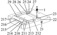
图1为本发明的基于柔顺并联机构的三轴刀具伺服装置的正三轴测图。FIG. 1 is a positive three-axis view of the three-axis tool servo device based on the compliant parallel mechanism of the present invention.
图2为图1中的单轴纳米定位平台的正三轴测图。FIG. 2 is a positive triaxial view of the uniaxial nanopositioning platform in FIG. 1 .
图3为图1中的三轴末端执行器的正三轴测图。FIG. 3 is a positive triaxial view of the three-axis end effector in FIG. 1 .
图4为图1中的第一外侧固定基座的正三轴测图。FIG. 4 is a normal triaxial view of the first outer fixing base in FIG. 1 .
图5为图1中的第二外侧固定基座的正三轴测图。FIG. 5 is an isometric view of the second outer fixing base in FIG. 1 .
图6为图1中的内侧固定基座的正三轴测图。FIG. 6 is an isometric view of the inner fixed base in FIG. 1 .
图7为图1中的三向加强筋的正三轴测图。FIG. 7 is a normal triaxial view of the three-direction reinforcing rib in FIG. 1 .
附图中:1-压电陶瓷驱动器;2-单轴纳米定位平台;21-顶丝;22-滚珠;23-预紧块;24-输入端导向柔顺铰链;25-输入端;26-一级杠杆输入点转动式柔顺铰链;27-一级杠杆支点处转动式柔顺铰链;28-一级杠杆主动杆;29-一级杠杆输出点转动式柔顺铰链;210-一级杠杆从动杆;211-二级杠杆输入点转动式柔顺铰链;212-二级杠杆支点处转动式柔顺铰链;213-二级杠杆主动杆;214-二级杠杆输出点转动式柔顺铰链;215-二级杠杆从动杆;216-二级杠杆从动杆输出端导向柔顺铰链;217-第一连接端;3-三轴末端执行器;311-Z向第二连接端;312-Z向连接杆;313-Z向输入点柔顺铰链;314-Z-Y解耦导向柔顺铰链;315-Z-X解耦导向柔顺铰链;321-Y向第二连接端;322-Y向连接杆;323-Y向输入点柔顺铰链;324-Y-Z解耦导向柔顺铰链;325-Y-X解耦导向柔顺铰链;331-X向第二连接端;332-X向连接杆;333-X向输入点柔顺铰链;334-X-Z解耦导向柔顺铰链;335-X-Y解耦导向柔顺铰链;34-刀具固定端和测量基准面;4-金刚石刀具;5-电容传感器;6-第一外侧固定基座;61-第一连接孔;62-第一散热栅;63-第一沉槽;64-电容传感器支架;7-第二外侧固定基座;71-第二连接孔;72-第二散热栅;73-第二沉槽;8-内侧固定基座;81-第一螺钉孔;82-第三散热栅;83-第一销钉孔;84 –第三沉槽;9-三向加强筋;91-第二螺钉孔;92-第二销钉孔。In the drawings: 1-piezoelectric ceramic driver; 2-uniaxial nano-positioning platform; 21-top wire; 22-ball; 23-preload block; 24-input end guide compliant hinge; 25-input end; 26-a Level 1 lever input point rotary compliant hinge; 27- level 1 lever fulcrum rotary compliant hinge; 28- level lever active rod; 29- level lever output point rotary compliant hinge; 210- level one lever driven rod; 211 - Rotary compliant hinge at the input point of the secondary lever; 212 - Rotary compliant hinge at the fulcrum of the secondary lever; 213 - Active lever of the secondary lever; 214 - Rotary compliant hinge at the output point of the secondary lever; 215 - Secondary lever from Moving rod; 216- secondary lever follower rod output end guide compliant hinge; 217- first connecting end; 3- three-axis end effector; 311- Z-direction second connecting end; 312-Z-direction connecting rod; 313- Z direction input point compliant hinge; 314-Z-Y decoupling guide compliant hinge; 315-Z-X decoupling guide compliant hinge; 321-Y second connecting end; 322-Y connecting rod; 323-Y input point compliant hinge; 324-Y-Z decoupling guide compliant hinge; 325-Y-X decoupling guide compliant hinge; 331-X to the second connecting end; 332-X to the connecting rod; 333-X to the input point compliant hinge; 334-X-Z decoupling guide compliant Hinge; 335-X-Y Decoupling Guided Compliant Hinge; 34-Tool Fixed End and Measurement Reference Surface; 4-Diamond Tool; 5-Capacitance Sensor; 6-First Outer Fixed Base; 61-First Connection Hole; a heat dissipation grid; 63-first sink; 64-capacitance sensor bracket; 7-second outer fixing base; 71-second connection hole; 72-second heat dissipation grid; 73-second sink; 8-inside Fixed base; 81-first screw hole; 82-third heat grid; 83-first pin hole; 84-third sink; 9-three-way reinforcing rib; 91-second screw hole; 92-second pin hole.
具体实施方式Detailed ways
下面结合具体实施方式对本发明作进一步的说明。其中,附图仅用于示例性说明,表示的仅是示意图,而非实物图,不能理解为对本专利的限制;为了更好地说明本发明的实施例,附图某些部件会有省略、放大或缩小,并不代表实际产品的尺寸;对本领域技术人员来说,附图中某些公知结构及其说明可能省略是可以理解的。The present invention will be further described below in conjunction with specific embodiments. Among them, the accompanying drawings are only used for exemplary description, and they are only schematic diagrams, not physical drawings, and should not be construed as restrictions on this patent; in order to better illustrate the embodiments of the present invention, some parts of the accompanying drawings will be omitted, The enlargement or reduction does not represent the size of the actual product; it is understandable to those skilled in the art that some well-known structures and their descriptions in the accompanying drawings may be omitted.
本发明实施例的附图中相同或相似的标号对应相同或相似的部件;在本发明的描述中,需要理解的是,若有术语“上”、“下”、“左”、“右”等指示的方位或位置关系为基于附图所示的方位或位置关系,仅是为了便于描述本发明和简化描述,而不是指示或暗示所指的装置或元件必须具有特定的方位、以特定的方位构造和操作,因此附图中描述位置关系的用语仅用于示例性说明,不能理解为对本专利的限制,对于本领域的普通技术人员而言,可以根据具体情况理解上述术语的具体含义。The same or similar numbers in the drawings of the embodiments of the present invention correspond to the same or similar components; in the description of the present invention, it should be understood that if there are terms “upper”, “lower”, “left” and “right” The orientation or positional relationship indicated by etc. is based on the orientation or positional relationship shown in the accompanying drawings, and is only for the convenience of describing the present invention and simplifying the description, rather than indicating or implying that the indicated device or element must have a specific orientation, with a specific orientation. Orientation structure and operation, so the terms describing the positional relationship in the accompanying drawings are only used for exemplary illustration, and should not be construed as a limitation on the present patent. Those of ordinary skill in the art can understand the specific meanings of the above terms according to specific situations.
实施例一Example 1
如图1至图7所示为本发明的基于柔顺并联机构的三轴刀具伺服装置的实施例,包括外侧固定基座、内侧固定基座8、通过第一运动支链传递运动的单轴纳米定位平台2以及通过第二运动支链导向和解耦的三轴末端执行器3,三组外侧固定基座、内侧固定基座8、单轴纳米定位平台2均两两正交,分别位于XOY平面、XOZ平面和YOZ平面,单轴纳米定位平台2设于外侧固定基座和内侧固定基座8之间,单轴纳米定位平台2与三轴末端执行器3连接;第一运动支链和第二运动支链均包括多种柔顺铰链和柔性杆件,第一运动支链和第二运动支链连接构成三条运动支链,把压电陶瓷驱动器1产生的力/位移/运动传递到三轴末端执行器3,三条运动支链并联连接且两两正交;三轴末端执行器3可外接不同类型的金刚石刀具4,包含由多组用于导向和解耦的柔顺铰链和柔性杆件构成的第二运动支链,设有用于位移闭环反馈检测的测量面;金刚石刀具4通过若干螺钉紧固在三轴末端执行器3的内部;三轴末端执行器3设有用于测量刀具4在空间三个正交直线轴X/Y/Z上位移量的电容传感器5,电容传感器5连接有控制器;控制器的输出端连接有压电陶瓷驱动器1,压电陶瓷驱动器1连接于单轴纳米定位平台2的输入端,三轴末端执行器3连接于三个单轴纳米定位平台2的输出端。1 to 7 are embodiments of the three-axis tool servo device based on a compliant parallel mechanism of the present invention, including an outer fixed base, an inner fixed
本实施例在实施时,金刚石刀具4三个直线轴的输出位移由电容传感器5直接检测,检测的数据反馈到控制器中,经预设算法计算得到输入端电压数据,输送到压电陶瓷驱动器1中,通过三条运动支链,实时控制三轴末端执行器3在不同直线轴的进给量,带动刀具4实现三轴纳米加工;柔顺铰链的设置可实现高功率的运动传递。In the implementation of this embodiment, the output displacement of the three linear axes of the diamond tool 4 is directly detected by the
如图2所示,单轴纳米定位平台2设有顶丝21、滚珠22(图中被遮挡)、预紧块23、输入端导向柔顺铰链24、输入端25、一级杠杆输入点转动式柔顺铰链26、一级杠杆支点处转动式柔顺铰链27、一级杠杆主动杆28、一级杠杆输出点转动式柔顺铰链29、一级杠杆从动杆210、二级杠杆输入点转动式柔顺铰链211、二级杠杆支点处转动式柔顺铰链212、二级杠杆主动杆213、二级杠杆输出点转动式柔顺铰链214、二级杠杆从动杆215、二级杠杆从动杆输出端导向柔顺铰链216、第一连接端217,压电陶瓷驱动器1的一端通过顶丝21与单轴纳米定位平台2的固定部分连接,若干杆件和柔顺铰链顺次串联设于输入端25和第一连接端217之间,输入端25与压电陶瓷驱动器1无间隙连接。其中,顶丝21的端面面接触设有滚珠22,滚珠22点接触设有用于测量预紧力的力传感器(图中未示出,实际使用中可以省略),力传感器与压电陶瓷驱动器1之间设有预紧块23,力传感器连接有控制器;预紧装置中使用滚珠22来实现预紧过程中的面接触或点接触,易于确定预紧力的作用点和作用方向,保证预紧精度,避免预紧过程中产生侧向力和弯矩,同时消除顶丝21转动产生的扭矩和侧向力,保护压电陶瓷驱动器1等所能承受扭矩受限的驱动器。顶丝21、滚珠22、力传感器、预紧块23、压电陶瓷驱动器1、输入端25、一级杠杆输入点转动式柔顺铰链26的轴线重合,采用顶丝21、滚珠22、力传感器和预紧块23来确保压电陶瓷驱动器1与输入端25的无间隙连接。柔顺铰链包括串联连接的输入端导向柔顺铰链24、一级杠杆输入点转动式柔顺铰链26、一级杠杆支点处转动式柔顺铰链27、一级杠杆输出点转动式柔顺铰链29、二级杠杆输入点转动式柔顺铰链211、二级杠杆支点处转动式柔顺铰链212、二级杠杆输出点转动式柔顺铰链214、二级杠杆从动杆输出端导向柔顺铰链216。预紧块23的顶部预留有用于安装测量块、反光镜支架的安装孔,安装测量块,便于电容传感器5对该测量块的测量面进行测量,也可以安装反光镜支架,使用激光干涉仪进行测量,校正或标定电容传感器5,也可监测预紧块23转动对电容传感器5直线位移测量精度的影响。本实施例中的力传感器用以测量预紧力的大小,也可以分别监测压电陶瓷驱动器1在整个工作过程中输出力的值并反馈回控制器,进而结合预紧块23、输入端25的位移来计算三条运动支链对应的预紧刚度和输入刚度。压电陶瓷驱动器1内置了高精度高带宽应变片传感器,实时测量数据与电容传感器5一起发送给控制器。输入端导向柔顺铰链24和二级杠杆从动杆输出端导向柔顺铰链216主要用于调节输入/输出刚度和耦合系数,与其他多组柔顺铰链和柔性杆件一起进行优化设计,可以实现预期的刚度和耦合系数。As shown in Figure 2, the
如图1所示,外侧固定基座包括位于XOZ平面和YOZ平面的第一外侧固定基座6和位于XOY平面的第二外侧固定基座7,两组第一外侧固定基座6垂直连接,第二外侧固定基座7相邻两边分别与第一外侧固定基座6垂直连接;三组内侧固定基座8的连接处设有三向加强筋9。本实施例的单轴纳米定位平台2两两之间、单轴纳米定位平台2与第一外侧固定基座6、单轴纳米定位平台2与第二外侧固定基座7、单轴纳米定位平台2与内侧固定基座8、内侧固定基座8与三向加强筋9之间分别采用若干垫片、螺钉和销钉等紧固在一起,三向加强筋9设有与螺钉配合的第二螺钉孔91以及与销钉配合的第二销钉孔92,使得单轴纳米定位平台2的固定部分、电容传感器5的支架相对于第一外侧固定基座6、第二外侧固定基座7、内侧固定基座8、三向加强筋9没有相对位移。As shown in Figure 1, the outer fixing base includes a first
如图3所示,第一外侧固定基座6分别位于XOZ平面和YOZ平面,通过若干螺钉和销钉分别与单轴纳米定位平台2连接;若干第一连接孔61对应单轴纳米定位平台2上的固定部分,进行二次加固;第一散热栅62对应单轴纳米定位平台2上安装压电陶瓷驱动器1的滑槽,第一沉槽63对应单轴纳米定位平台2上传递力和位移的多组杆件及柔顺铰链,避免产生运动干涉,也通过间隙和栅孔进行散热,确保压电陶瓷驱动器1高功率工况下的稳定性;两个电容传感器支架64呈正交分布,通过若干螺钉和销钉与电容传感器支架的另一部分连接,用于固定电容传感器5;为加强支架64的刚度,设有若干加强筋等。As shown in FIG. 3 , the first
如图4所示,第二外侧固定基座7位于XOY平面,结构与第一外侧固定基座相似,通过若干螺钉和销钉分别与单轴纳米定位平台2连接;若干第二连接孔71对应单轴纳米定位平台2上的固定部分,进行二次加固;第二散热栅72对应单轴纳米定位平台2上安装压电陶瓷驱动器1的滑槽,第二沉槽73对应单轴纳米定位平台2上传递力和位移的多组柔顺铰链及柔性杆件,避免产生运动干涉,也通过第二散热栅72进行散热,确保压电陶瓷驱动器1和单轴纳米定位平台2高功率工况下的稳定性。As shown in FIG. 4 , the second outer fixing
如图5所示,三个内侧固定基座8分别位于XOY平面、XOZ平面和YOZ平面,通过若干螺钉和销钉分别与单轴纳米定位平台2连接;若干第一螺钉孔81对应单轴纳米定位平台2上的固定部分,进行三次加固;第三散热栅82对应单轴纳米定位平台2上安装压电陶瓷驱动器1的滑槽,第三沉槽84对应单轴纳米定位平台2上传递力和位移的多组柔顺铰链及柔性杆件,避免产生运动干涉,也通过间隙和栅孔进行散热,确保压电陶瓷驱动器1和单轴纳米定位平台2高功率工况下的稳定性;若干第一销钉孔83和第一螺钉孔81用于和三向加强筋9连接。As shown in FIG. 5 , the three
如图6所示,三向加强筋9呈立体结构,三条支链分别通过若干螺钉和销钉与内侧固定基座8连接,提高内侧固定基座8的刚度,也作为整个三轴刀具伺服装置的加强筋,提高装置结构刚度;预留多组螺钉孔和销钉孔,配合构型和尺寸的灵活设计,用于集成到不同的超精密加工机床、精密测量、微纳制造等多种精密装备/仪器/设备中。As shown in FIG. 6 , the three-
如图7所示,三轴末端执行器3包括三条分别对应于X轴、Y轴、Z轴的由多组柔顺铰链和柔性杆件构成的第二运动支链;第二运动支链包括依次串联的第二连接端、连接杆、输入点柔顺铰链以及解耦导向柔顺铰链,第二连接端与第一连接端连接,通过刀具固定端34与刀具4连接。具体地,三轴末端执行器3在Z向、Y向、X向三个方向的第二连接端Z向连接端311、Y向连接端321、X向连接端331通过若干沉槽、螺钉和销钉分别与三个单轴纳米定位平台2连接;三轴末端执行器3包含三条由多组柔顺铰链和柔性杆件构成的第二运动支链,分别对应Z轴、Y轴和X轴,每条轴均依次串联轴向柔顺铰链、杆件和若干组导向柔顺铰链等;对于Z轴方向,依次串联Z向连接端311、Z向连接杆312、Z向输入点柔顺铰链313、Z-Y解耦导向柔顺铰链314、Z-X解耦导向柔顺铰链315;对于Y轴方向,依次串联Y向连接端321、Y向连接杆322、Y向输入点柔顺铰链323、Y-Z解耦导向柔顺铰链324、Y-X解耦导向柔顺铰链325;对于X轴方向,依次串联X向连接端331、X向连接杆332、X向输入点柔顺铰链333、X-Z解耦导向柔顺铰链334、X-Y解耦导向柔顺铰链335;配合单轴纳米定位平台2的多组柔顺铰链,实现导向和多轴解耦,易于设计多轴联动的控制器;三轴末端执行器3通过若干螺钉对金刚石刀具4进行加固;本实施例的三轴末端执行器3具有三个直线轴的自由度,金刚石刀具4也具有与之相同的自由度;三轴末端执行器3设有四个测量面,分别对应四支电容传感器5;其中,三轴末端执行器3在空间三个正交直线轴X/Y/Z上的位移量被电容传感器5直接测量得到,发送给控制器(图中未示出);同在一个轴上的两支电容传感器5可以相互校对,也可以测量三轴末端执行器直线运动轴以外的角度耦合位移量;三轴末端执行器3预留接口,可以外接激光干涉仪(图中未示出)、激光尺(图中未示出)、三坐标测量机(图中未示出)或激光追踪仪(图中未示出)等,用于对装置本身自带电容传感器5的测量数据进行评估、校对或验证;电容传感器5的支架安装精度、与被测量面的平行度和初始距离使用塞尺(图中未示出)等确定;本实施例采用的电容传感器5为柱状结构,也可以采用片式结构或其他类型的微位移传感器进行测量;本实施例采用的三轴末端执行器3也可以外接精密测量头、成像装置、样品台等,集成到多种类型的精密装备/仪器/设备中。As shown in FIG. 7 , the three-
本实施例中柔顺并联机构的静力学、运动学和动力学特性取决于三条运动支链的多组柔顺铰链和柔性杆件等,可通过对结构参数的优化设计,实现机构多项性能指标的组合优化,满足不同应用场景下对性能图谱的偏好需求。The statics, kinematics and dynamic characteristics of the compliant parallel mechanism in this embodiment depend on multiple sets of compliant hinges and flexible rods of the three kinematic branches. By optimizing the design of the structural parameters, it is possible to achieve the optimal performance of multiple performance indicators of the mechanism. Combination optimization to meet the preference requirements for performance graphs in different application scenarios.
显然,本发明的上述实施例仅仅是为清楚地说明本发明所作的举例,而并非是对本发明的实施方式的限定。对于所属领域的普通技术人员来说,在上述说明的基础上还可以做出其它不同形式的变化或变动。这里无需也无法对所有的实施方式予以穷举。凡在本发明的精神和原则之内所作的任何修改、等同替换和改进等,均应包含在本发明权利要求的保护范围之内。Obviously, the above-mentioned embodiments of the present invention are only examples for clearly illustrating the present invention, rather than limiting the embodiments of the present invention. For those of ordinary skill in the art, changes or modifications in other different forms can also be made on the basis of the above description. There is no need and cannot be exhaustive of all implementations here. Any modifications, equivalent replacements and improvements made within the spirit and principle of the present invention shall be included within the protection scope of the claims of the present invention.
Claims (4)
Priority Applications (1)
| Application Number | Priority Date | Filing Date | Title |
|---|---|---|---|
| CN201810931177.1A CN109079552B (en) | 2018-08-15 | 2018-08-15 | Triaxial cutter servo device based on compliant parallel mechanism |
Applications Claiming Priority (1)
| Application Number | Priority Date | Filing Date | Title |
|---|---|---|---|
| CN201810931177.1A CN109079552B (en) | 2018-08-15 | 2018-08-15 | Triaxial cutter servo device based on compliant parallel mechanism |
Publications (2)
| Publication Number | Publication Date |
|---|---|
| CN109079552A CN109079552A (en) | 2018-12-25 |
| CN109079552B true CN109079552B (en) | 2020-06-30 |
Family
ID=64793724
Family Applications (1)
| Application Number | Title | Priority Date | Filing Date |
|---|---|---|---|
| CN201810931177.1A Active CN109079552B (en) | 2018-08-15 | 2018-08-15 | Triaxial cutter servo device based on compliant parallel mechanism |
Country Status (1)
| Country | Link |
|---|---|
| CN (1) | CN109079552B (en) |
Families Citing this family (6)
| Publication number | Priority date | Publication date | Assignee | Title |
|---|---|---|---|---|
| CN110253340B (en) * | 2019-06-26 | 2020-08-11 | 浙江大学 | Three-dimensional force detection system based on three-axis quick cutter servo mechanism |
| CN111633451B (en) * | 2020-04-14 | 2021-08-31 | 浙江大学 | Three-dimensional force detection system of three-axis fast tool servo mechanism |
| CN114406773B (en) * | 2022-01-26 | 2023-03-24 | 哈尔滨工业大学(深圳) | Two-degree-of-freedom cutter servo device |
| CN115224975B (en) * | 2022-07-22 | 2024-06-18 | 山东大学 | An orthogonal decoupled three-axis nano-motion platform for inverted load application |
| CN116117774B (en) * | 2023-02-10 | 2025-08-29 | 中国科学院高能物理研究所 | A three-axis parallel decoupling motion platform |
| CN119609735B (en) * | 2023-09-13 | 2025-10-21 | 南京理工大学 | A topologically optimized dual-axis decoupling tool servo device and its design method |
Family Cites Families (8)
| Publication number | Priority date | Publication date | Assignee | Title |
|---|---|---|---|---|
| CN1233511C (en) * | 2002-05-23 | 2005-12-28 | 河北工业大学 | Recombineable modular 3-6 freedom structure decoupling parallel micro moving robot |
| TW200618932A (en) * | 2004-12-07 | 2006-06-16 | Rong-Fong Fung | XYθz self-propelled micro/nano precision platform |
| CN102059575B (en) * | 2010-11-26 | 2012-10-10 | 吉林大学 | Method and device for generating three-dimensional elliptical motion of diamond cutting tool |
| CN202428438U (en) * | 2012-01-12 | 2012-09-12 | 燕山大学 | Six-freedom-degree parallel connection micro robot |
| CN102756366A (en) * | 2012-06-28 | 2012-10-31 | 燕山大学 | Space decoupling three-dimensional motion parallel micro-motion mechanism |
| CN104440817B (en) * | 2014-12-04 | 2017-04-12 | 山东大学 | Spatial three-dimensional micro-displacement precise positioning device |
| CN106195541B (en) * | 2016-07-04 | 2018-04-27 | 山东大学 | A kind of Three Degree Of Freedom Piezoelectric Driving micro-nano locating platform |
| CN106514631B (en) * | 2017-01-12 | 2018-01-16 | 广东工业大学 | The plane XY θ Three Degree Of Freedom accuracy compensation devices that a kind of flexible hinge is oriented to |
-
2018
- 2018-08-15 CN CN201810931177.1A patent/CN109079552B/en active Active
Also Published As
| Publication number | Publication date |
|---|---|
| CN109079552A (en) | 2018-12-25 |
Similar Documents
| Publication | Publication Date | Title |
|---|---|---|
| Tian et al. | A novel XYZ micro/nano positioner with an amplifier based on L-shape levers and half-bridge structure | |
| US6467761B1 (en) | Positioning stage | |
| CN108527334B (en) | Multi-degree-of-freedom compliant parallel mechanism | |
| Tian et al. | A flexure-based five-bar mechanism for micro/nano manipulation | |
| CN103557412B (en) | Bipolar two-dimensional Grazing condition high-precision servo platform | |
| CN109502542B (en) | Multi-degree-of-freedom nanometer positioning platform based on compliant parallel mechanism | |
| CN109079552A (en) | A kind of three axis cutter servo devices based on compliant parallel mechanism | |
| CN104110561B (en) | A kind of large-range plane three-freedom degree precision locating platform based on compliant mechanism | |
| US6484602B1 (en) | Six-degree of freedom micro-positioner | |
| CN105291090A (en) | Parallel type macro-micro high-precision movement platform | |
| CN106195541A (en) | A kind of Three Degree Of Freedom Piezoelectric Driving micro-nano locating platform | |
| JP7125215B2 (en) | measurement system | |
| CN114649976B (en) | Piezoelectric driving six-degree-of-freedom compliant positioning system and control method thereof | |
| CN102069201B (en) | Two-degree-of-freedom dynamic error counteracting device for free-form surface ultra-precision turning | |
| CN106272353A (en) | A kind of planar three freedom meek parallel institution of large stroke and high precision | |
| CN211087931U (en) | Three-degree-of-freedom micro-nano positioning platform | |
| CN217183193U (en) | Piezoelectric-driven six-degree-of-freedom compliant positioning system | |
| Jiang et al. | Design, development, and application of a compact flexure-based decoupler with high motion transmission efficiency and excellent input decoupling performance | |
| Zhang et al. | A high-bandwidth compact micro/nano-positioning stage based on a double parallelogram compliant mechanism | |
| JP2012076188A (en) | Parallel link mechanism and driving stage | |
| JP4311621B2 (en) | Mechanical motion error correction method using a 6-DOF position and orientation measurement device | |
| Shin et al. | Design of a double triangular parallel mechanism for precision positioning and large force generation | |
| CN114928270A (en) | Compliance control device based on compliance mechanism and compliance control method thereof | |
| CN109949856B (en) | Modularized six-degree-of-freedom precise micro-motion mechanism based on flexible hinge | |
| US20030033703A1 (en) | Positioning stage |
Legal Events
| Date | Code | Title | Description |
|---|---|---|---|
| PB01 | Publication | ||
| PB01 | Publication | ||
| SE01 | Entry into force of request for substantive examination | ||
| SE01 | Entry into force of request for substantive examination | ||
| GR01 | Patent grant | ||
| GR01 | Patent grant |