CN109027560B - High-precision XY moving platform and implementation method thereof - Google Patents
High-precision XY moving platform and implementation method thereof Download PDFInfo
- Publication number
- CN109027560B CN109027560B CN201811068757.9A CN201811068757A CN109027560B CN 109027560 B CN109027560 B CN 109027560B CN 201811068757 A CN201811068757 A CN 201811068757A CN 109027560 B CN109027560 B CN 109027560B
- Authority
- CN
- China
- Prior art keywords
- driving
- move
- driving part
- axis
- sliding block
- Prior art date
- Legal status (The legal status is an assumption and is not a legal conclusion. Google has not performed a legal analysis and makes no representation as to the accuracy of the status listed.)
- Active
Links
Images


Classifications
-
- F—MECHANICAL ENGINEERING; LIGHTING; HEATING; WEAPONS; BLASTING
- F16—ENGINEERING ELEMENTS AND UNITS; GENERAL MEASURES FOR PRODUCING AND MAINTAINING EFFECTIVE FUNCTIONING OF MACHINES OR INSTALLATIONS; THERMAL INSULATION IN GENERAL
- F16M—FRAMES, CASINGS OR BEDS OF ENGINES, MACHINES OR APPARATUS, NOT SPECIFIC TO ENGINES, MACHINES OR APPARATUS PROVIDED FOR ELSEWHERE; STANDS; SUPPORTS
- F16M11/00—Stands or trestles as supports for apparatus or articles placed thereon Stands for scientific apparatus such as gravitational force meters
- F16M11/02—Heads
- F16M11/04—Means for attachment of apparatus; Means allowing adjustment of the apparatus relatively to the stand
- F16M11/043—Allowing translations
- F16M11/045—Allowing translations adapted to left-right translation movement
-
- F—MECHANICAL ENGINEERING; LIGHTING; HEATING; WEAPONS; BLASTING
- F16—ENGINEERING ELEMENTS AND UNITS; GENERAL MEASURES FOR PRODUCING AND MAINTAINING EFFECTIVE FUNCTIONING OF MACHINES OR INSTALLATIONS; THERMAL INSULATION IN GENERAL
- F16H—GEARING
- F16H25/00—Gearings comprising primarily only cams, cam-followers and screw-and-nut mechanisms
- F16H25/18—Gearings comprising primarily only cams, cam-followers and screw-and-nut mechanisms for conveying or interconverting oscillating or reciprocating motions
- F16H25/20—Screw mechanisms
- F16H25/2018—Screw mechanisms with both screw and nut being driven, i.e. screw and nut are both rotating
-
- F—MECHANICAL ENGINEERING; LIGHTING; HEATING; WEAPONS; BLASTING
- F16—ENGINEERING ELEMENTS AND UNITS; GENERAL MEASURES FOR PRODUCING AND MAINTAINING EFFECTIVE FUNCTIONING OF MACHINES OR INSTALLATIONS; THERMAL INSULATION IN GENERAL
- F16M—FRAMES, CASINGS OR BEDS OF ENGINES, MACHINES OR APPARATUS, NOT SPECIFIC TO ENGINES, MACHINES OR APPARATUS PROVIDED FOR ELSEWHERE; STANDS; SUPPORTS
- F16M11/00—Stands or trestles as supports for apparatus or articles placed thereon Stands for scientific apparatus such as gravitational force meters
- F16M11/02—Heads
- F16M11/04—Means for attachment of apparatus; Means allowing adjustment of the apparatus relatively to the stand
- F16M11/043—Allowing translations
- F16M11/048—Allowing translations adapted to forward-backward translation movement
-
- F—MECHANICAL ENGINEERING; LIGHTING; HEATING; WEAPONS; BLASTING
- F16—ENGINEERING ELEMENTS AND UNITS; GENERAL MEASURES FOR PRODUCING AND MAINTAINING EFFECTIVE FUNCTIONING OF MACHINES OR INSTALLATIONS; THERMAL INSULATION IN GENERAL
- F16M—FRAMES, CASINGS OR BEDS OF ENGINES, MACHINES OR APPARATUS, NOT SPECIFIC TO ENGINES, MACHINES OR APPARATUS PROVIDED FOR ELSEWHERE; STANDS; SUPPORTS
- F16M11/00—Stands or trestles as supports for apparatus or articles placed thereon Stands for scientific apparatus such as gravitational force meters
- F16M11/02—Heads
- F16M11/18—Heads with mechanism for moving the apparatus relatively to the stand
-
- H—ELECTRICITY
- H02—GENERATION; CONVERSION OR DISTRIBUTION OF ELECTRIC POWER
- H02K—DYNAMO-ELECTRIC MACHINES
- H02K7/00—Arrangements for handling mechanical energy structurally associated with dynamo-electric machines, e.g. structural association with mechanical driving motors or auxiliary dynamo-electric machines
- H02K7/06—Means for converting reciprocating motion into rotary motion or vice versa
Abstract
The invention provides a high-precision XY moving platform and an implementation method thereof, wherein an X-axis driving mechanism provided with a first driving part and a second driving part and a Y-axis driving mechanism provided with a third driving part and a fourth driving part are arranged; the first driving part drives the sliding block to move, and the second driving part drives the sliding block to move in the same direction and different forces; the third driving part drives the Y-axis driving mechanism to move with the same direction and different forces as the fourth driving part drives the Y-axis driving mechanism to move. Because the first driving part and the second driving part or the third driving part and the fourth driving part always control the driving and the sliding block to be in a contact state and move along one direction, the phenomenon of idle return in the process of back-and-forth movement is eliminated, and the sliding block is controlled with high precision.
Description
Technical Field
The invention relates to the technical field of precision positioning equipment, in particular to a high-precision XY moving platform and an implementation method thereof.
Background
The high-precision motor is expensive and difficult to realize, for example, precision control of a microscope slide glass needs precision adaptation, for example, the motor drives a screw rod, the screw rod drives a sliding block, a gap between the sliding block and the screw rod needs precision adaptation, however, the matching of the sliding block and the screw rod has redundancy, particularly, under the requirement of high-precision driving, the adaptation redundancy of the sliding block and the screw rod is small, and on the other hand, when the redundancy is too small, the driving tension is too large, the abrasion is easy to be serious, the service life is limited, and the cost is increased.
The existing adaptation of the screw rod and the sliding block always has the matching tolerance of 40-50 threads (one thread is equal to 10 microns), so that in the high-precision control of the sliding block, ideal matching clearance-free is difficult to achieve, so that when the sliding block is driven to one side, the control of motor driving can be very accurate, but when the sliding block is controlled to the opposite direction, the matching tolerance of the sliding block and the screw rod can be found to be a serious problem of influencing the precision: due to the existence of the fit tolerance, the sliding block has a certain backlash phenomenon, so that the position of the sliding block is difficult to be accurately controlled in the accurate control of the motor.
The existing XY moving platform comprises a driving motor in an X-axis control direction and a driving motor in a Y-axis control direction, so that the accurate control of the two driving motors on the position of the sliding block also affects the accurate control of the whole XY moving platform on the position of the sliding block, how to overcome the backlash phenomenon generated when the motors control the movement of the sliding block, and how to improve the accurate control of the position of the sliding block is the problem to be solved in the current position control.
Therefore, the prior art is subject to further improvement.
Disclosure of Invention
In view of the defects in the prior art, the invention aims to provide a high-precision XY moving platform and an implementation method thereof for a user, and overcomes the defect that the position of a sliding block cannot be accurately controlled due to the existence of a backlash phenomenon when the XY moving platform drives the sliding block to move in the prior art.
The technical scheme disclosed by the invention is as follows:
a high precision XY motion stage, comprising: an X-axis driving mechanism and a Y-axis driving mechanism;
the Y-axis drive mechanism includes: a Y-axis guide rail and a slider; the X-axis drive mechanism includes: a Y-axis base and an X-axis guide rail; the Y-axis driving mechanism is arranged above the X-axis driving mechanism, and the X-axis driving mechanism drives the Y-axis driving mechanism to drive the sliding block to move;
the Y-axis drive mechanism further includes:
the first driving part and the second driving part are arranged above the Y-axis guide rail; the first driving component drives the slider to move in a direction opposite to the direction in which the second driving component drives the slider to move; after the first driving part drives the sliding block to move to the end point of the Y-axis guide rail, the impedance of the first driving part is firstly adopted and the second driving part drives the sliding block to move, and then the second driving part drives the sliding block to move;
the X-axis drive mechanism includes:
a third drive member and a fourth drive member disposed above the X-axis guide rail; the third driving part drives the Y-axis driving mechanism to move with the same direction and different forces as the fourth driving part drives the Y-axis driving mechanism to move.
Optionally, the first driving part comprises: the first screw rod is arranged on the Y-axis guide rail, and the first driving motor is arranged at one end side of the first screw rod;
the second drive member includes: the second screw rod is arranged on the Y-axis guide rail, and the second driving motor is arranged at one end side of the second screw rod;
the first driving motor is used for driving the first screw rod to move when the XY moving platform is positioned at a first station;
the second driving motor is used for driving the second screw rod to move when the XY moving platform is positioned at a second station;
the first driving motor drives the first screw rod to move, and the second driving motor drives the second screw rod to move in the same direction and different forces.
Optionally, the first screw rod and the second screw rod are arranged side by side.
Optionally, the third driving part includes: the third screw rod is arranged on the X-axis guide rail, and the third driving motor is arranged at one end side of the third screw rod;
the fourth drive member includes: the fourth screw rod is arranged on the X-axis guide rail, and the fourth driving motor is arranged at one end side of the fourth screw rod;
the third driving motor is used for driving the third screw rod to move when the XY moving platform is positioned at a third station;
the fourth driving motor is used for driving the fourth screw rod to move when the XY moving platform is positioned at a fourth station;
the third driving motor drives the third screw rod to move, and the fourth driving motor drives the fourth screw rod to move in the same direction and with different forces.
Optionally, the third screw rod and the fourth screw rod are arranged side by side.
Optionally, the first driving motor and the second driving motor are respectively arranged at two ends of the first lead screw and the second lead screw; or the first driving motor and the second driving motor are both arranged at the same end of the first screw rod and the second screw rod.
Optionally, the third driving motor and the fourth driving motor are respectively arranged at two ends of the third screw rod and the fourth screw rod; or the third driving motor and the fourth driving motor are both arranged at the same end of the third screw rod and the fourth screw rod.
Optionally, the slider further includes: the top plate, the first positioning block and the second positioning block which are respectively sleeved on the first screw rod and the second screw rod, the first sliding block which is positioned below the first positioning block and the second sliding block which is positioned below the second positioning block.
Optionally, the Y-axis driving mechanism is further provided with: a third positioning block and a fourth positioning block which are respectively sleeved on the third screw rod and the fourth screw rod, and a third sliding block positioned below the third positioning block and a fourth sliding block positioned below the fourth positioning block;
and the third sliding block and the fourth sliding block are movably connected with the sliding guide rail of the X-axis driving mechanism.
On the basis of the XY moving platform, the invention also discloses a method for realizing the high-precision XY moving platform, which comprises the following steps:
arranging an X-axis driving mechanism provided with a first driving part and a second driving part and a Y-axis driving mechanism provided with a third driving part and a fourth driving part;
controlling the first driving part to drive the sliding block to move when the XY moving platform is positioned at a first station, or controlling the second driving part to drive the sliding block to move when the XY moving platform is positioned at a second station;
and/or controlling the direction of the Y-axis driving mechanism driven by the third driving part when the XY moving platform is at the third station, or controlling the Y-axis driving mechanism driven by the fourth driving part when the XY moving platform is at the fourth station;
the first driving part drives the sliding block to move, and the second driving part drives the sliding block to move in the same direction and different forces; the third driving part drives the Y-axis driving mechanism to move, and the fourth driving part drives the Y-axis driving mechanism to move with different forces in the same direction;
and after the first driving part drives the sliding block to move to the end point of the Y-axis guide rail, the first driving part adopts the impedance of the first driving part and drives the idle return by the second driving part, and then the second driving part drives the sliding block to move.
The invention has the beneficial effects that the invention provides a high-precision XY moving platform and an implementation method thereof, wherein an X-axis driving mechanism and a Y-axis driving mechanism are arranged; and controlling the first driving part to drive the sliding block to move when the XY moving platform is positioned at the first station and the second driving part to drive the sliding block to move in the same direction and different forces when the motor is positioned at the second station, or controlling the third driving part to drive the Y-axis driving mechanism to move when the XY moving platform is positioned at the third station and the fourth driving part to drive the Y-axis driving mechanism to move in the same direction and different forces when the motor is positioned at the fourth station. The first driving part or the second driving part drives and controls the sliding block to move, or when the third driving part and the fourth driving part drive the Y-axis driving mechanism to move, the driving direction is always kept unchanged, before the movement track is switched, the backlash of the current movement track is eliminated through impedance and the driving force of the part to be driven, and then the movement track is switched to start the movement in the opposite direction, so that the backlash phenomenon in the reciprocating movement process is eliminated, and the high-precision control of the sliding block is realized.
Drawings
FIG. 1 is a schematic structural diagram of a high-precision XY moving platform provided by the present invention;
FIG. 2 is a schematic structural diagram of a Y-axis driving mechanism in the XY moving stage according to the present invention;
FIG. 3 is an exploded view of the Y-axis drive mechanism provided by the present invention;
fig. 4 is a flow chart of the steps of the implementation method provided by the invention.
Detailed Description
In order to make the objects, technical solutions and advantages of the present invention clearer and clearer, the present invention is further described in detail below with reference to the accompanying drawings and examples. It should be understood that the specific embodiments described herein are merely illustrative of the invention and are not intended to limit the invention.
Because the prior art generally uses a motor to realize the high-precision control of the reciprocating position of the sliding block, and because the driving part and the sliding block can not be completely attached, a certain degree of adaptability is needed, the reciprocating driving process has a backlash phenomenon, and the precision of position control is improved through precise adaptation, which can cause very high cost.
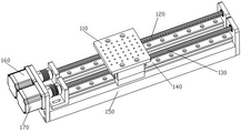
The invention discloses a high-precision XY moving platform, as shown in figures 1 and 2, comprising: an X-axis drive mechanism 20 and a Y-axis drive mechanism 10; the Y-axis drive mechanism 10 includes: a Y-axis guide rail and a slider; the X-axis drive mechanism includes: y axle base and X axle guide rail.
The Y-axis driving mechanism 10 is arranged above the X-axis driving mechanism 20; the X-axis driving mechanism 20 drives the Y-axis driving mechanism 10 to drive the sliding block 110 to move;
the Y-axis drive mechanism 10 further includes:
a first drive member and a second drive member disposed above the guide rail; the direction of the first driving part driving the sliding block to move is different from the direction of the second driving part driving the sliding block to move;
the X-axis drive mechanism 20 includes:
a third driving part and a fourth driving part disposed above the guide rail; the third driving part drives the Y-axis driving mechanism to move with the same direction and different forces as the fourth driving part drives the Y-axis driving mechanism to move.
Specifically, the fact that the direction in which the first driving component drives the slider to move and the direction in which the second driving component drives the slider to move are the same and different forces means that: the direction of the first driving part driving the slider to move is the same as the direction of the second driving part driving the slider to move, that is, in the process of driving the slider to move, the directions of the two driving forces are the same, but the magnitudes of the driving forces are different. When the actual working load is larger, the driving device can also be used as a drive.
Similarly, the fact that the direction in which the third driving part drives the Y-axis driving mechanism to move and the direction in which the fourth driving part drives the Y-axis driving mechanism to move are the same and different means that: the direction in which the third driving part drives the Y-axis driving mechanism to move is the same as the direction in which the fourth driving part drives the Y-axis driving mechanism to move, that is, in the process of driving the Y-axis driving mechanism to move, the directions of the two driving forces are the same, but the magnitudes of the driving forces are different, when the third driving part drives the Y-axis driving mechanism to move in the first direction, the driving force of the third driving part is the main driving force, the driving force of the fourth driving part is the auxiliary driving force, the main driving force is greater than the auxiliary driving force, and the auxiliary driving can be understood as an adjustable load. When the actual working load is larger, the driving device can also be used as a drive.
As can be seen from the above, the XY stage apparatus disclosed in the present invention has four stations, but there are four stations in the directions in which the sliders can be driven by different driving members, respectively, two opposite directions along the Y axis and two opposite directions along the X axis. The slider moves in one direction through a specific driving part, so that the reciprocating motion phenomenon cannot occur in the process of controlling the slider to move by each driving mechanism, before the slider is switched from a first sliding track to a second sliding track to move, the resistance of the first driving part and the driving of the second driving part are firstly utilized to eliminate the idle loop generated in the driving motion of the first driving part, before the second sliding track is started to move, the driving motion of the second driving part is started after the second sliding track is accurately positioned, and the idle loop caused when the same driving part is used for driving the slider to move back and forth is avoided. The method is simple and low in cost. Similarly, in the X-axis driving mechanism, when the third driving part and the fourth distinguishing part drive the Y-axis driving mechanism to move, before the switching of the moving tracks occurs, the backlash generated in the current moving track is eliminated, and then the movement determination of the first track is started, so that the accurate control of the driving movement is realized.
As shown in fig. 2, the Y-axis driving mechanism disclosed in the present invention includes: base 150 and Y-axis guide 140, further include: a slider 110; and a first drive member and a second drive member disposed above the Y-axis guide rail 140;
the first drive member includes: a first lead screw 120 and a first driving motor 160 provided on the Y-axis guide rail;
the second drive member includes: a second screw 130 and a second driving motor 170 disposed on the Y-axis guide rail;
the first driving motor 160 is configured to drive the first lead screw 120 to move when the motor implementation device is located at the first station;
the second driving motor 170 is configured to drive the second lead screw 130 to move when the motor implementation device is located at the second station;
the direction of the first driving motor 160 driving the first screw rod to move 120 is opposite to the direction of the second driving motor 170 driving the second screw rod to move 130.
Similarly, the third driving part includes: the third screw rod is arranged on the X-axis guide rail, and the third driving motor is arranged at one end side of the third screw rod;
the fourth drive member includes: the fourth screw rod is arranged on the X-axis guide rail, and the fourth driving motor is arranged at one end side of the fourth screw rod;
the third driving motor is used for driving the third screw rod to move when the XY moving platform is positioned at a third station;
the fourth driving motor is used for driving the fourth screw rod to move when the XY moving platform is positioned at a fourth station;
the third driving motor drives the third screw rod to move, and the fourth driving motor drives the fourth screw rod to move in the same direction and with different forces.
Preferably, in order to achieve the same front and rear driving effect, the first lead screw 120 and the second lead screw 130 are arranged side by side. Preferably, the third screw rod and the fourth screw rod are arranged side by side.
It is conceivable that the first and second driving motors 160 and 170 are respectively provided at both ends of the first and second lead screws 120 and 130; or the first driving motor 160 and the second driving motor 170 are both disposed at the same side end of the first lead screw 120 and the second lead screw 130. That is, the first driving motor 160 and the second driving motor 170 may be disposed at the same end of the lead screw or disposed at both ends of the first lead screw 120 and the second lead screw 130, respectively, as long as the direction of controlling the movement of the first lead screw and the movement of the second lead screw are different in the same direction.
Similarly, the third driving motor and the fourth driving motor are respectively arranged at two ends of the third screw rod and the fourth screw rod; or the third driving motor and the fourth driving motor are both arranged at the same end of the third screw rod and the fourth screw rod.
Specifically, as shown in fig. 3, the explosion diagram of the linear module is shown, wherein the first lead screw and the second lead screw are arranged side by side, and the slider includes: the top plate, the first positioning block and the second positioning block which are respectively sleeved on the first screw rod and the second screw rod, and the first fixing block and the second fixing block which are respectively sleeved on the Y-axis driving slide rail. As can be seen from fig. 3, the first positioning block and the second positioning block are symmetrically disposed, the first fixing block and the second fixing block are also symmetrically disposed, and the top plate, the first positioning block, the second positioning block are fixed, and the first fixing block and the second fixing block are fixedly connected. The first driving motor and the second driving motor are respectively connected with the first screw rod and the second screw rod.
When the sliding block needs to be driven to a specific direction, one of the two driving parts can be used, the sliding block moves under the driving of the first screw rod or the second screw rod, and when the sliding block needs to be driven to the direction opposite to the specific direction, the sliding block can be driven to the opposite direction with the other screw rod, so that the movement in the two directions is realized under different driving parts, and the phenomenon of backlash caused by the fact that the same driving part needs to be driven back and forth is avoided.
The X-axis driving mechanism is also provided with a base; a third positioning block and a fourth positioning block which are respectively sleeved on the third screw rod and the fourth screw rod, and a third sliding block positioned below the third positioning block and a fourth sliding block positioned below the fourth positioning block; and the third sliding block and the fourth sliding block are movably connected with the X-axis guide rail. The X-axis guide rail comprises a left guide rail and a right guide rail which are symmetrical, and a third sliding block and a fourth sliding block are respectively connected with the left guide rail and the right guide rail. When the XY platform executes the third station and the fourth station, the slide block can be driven by the third screw rod and the fourth screw rod to move on the left guide rail and the right guide rail respectively in two directions of the X axis.
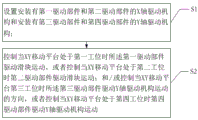
On the basis of the XY moving platform, the invention also discloses a method for realizing the high-precision XY moving platform, which comprises the following steps of:
step S1, setting an X-axis driving mechanism provided with a first driving part and a second driving part and a Y-axis driving mechanism provided with a third driving part and a fourth driving part;
step S2, controlling the first driving part to drive the sliding block to move when the XY moving platform is at the first station, or controlling the second driving part to drive the sliding block to move when the XY moving platform is at the second station;
and/or controlling the direction of the Y-axis driving mechanism driven by the third driving part when the XY moving platform is at the third station, or controlling the Y-axis driving mechanism driven by the fourth driving part when the XY moving platform is at the fourth station;
the first driving part drives the sliding block to move, and the second driving part drives the sliding block to move in the same direction and different forces; the third driving part drives the Y-axis driving mechanism to move, and the fourth driving part drives the Y-axis driving mechanism to move with different forces in the same direction;
and after the first driving part drives the sliding block to move to the end point of the Y-axis guide rail, the impedance of the first driving part is firstly adopted and the second driving part drives the sliding block to move to eliminate backlash, and then the second driving part drives the sliding block to move.
That is, during the control operation, one of the four stations can be independently started for use, and one station can be selected from the X-axis driving mechanism and the Y-axis driving mechanism to be started for use.
The invention discloses a high-precision XY platform device and an implementation method thereof.A first driving part or a second driving part drives and controls a sliding block to move or a third driving part and a fourth driving part drive a Y-axis driving mechanism to move, the driving direction is always kept unchanged, before a moving track is switched, the idle return of the current moving track is eliminated through impedance and the driving force of a part to be driven, and then the moving track is switched to start the movement in the opposite direction, so that the idle return phenomenon in the back-and-forth movement process is eliminated, and the high-precision control of the sliding block and the Y-axis driving mechanism is realized.
It should be understood that equivalents and modifications of the technical solution and inventive concept thereof may occur to those skilled in the art, and all such modifications and alterations should fall within the scope of the appended claims.
Claims (10)
1. A high-precision XY moving platform, comprising: an X-axis driving mechanism and a Y-axis driving mechanism;
the Y-axis drive mechanism includes: a Y-axis guide rail and a slider; the X-axis drive mechanism includes: a Y-axis base and an X-axis guide rail;
the Y-axis driving mechanism is arranged above the X-axis driving mechanism, and the X-axis driving mechanism drives the Y-axis driving mechanism to drive the sliding block to move;
the Y-axis drive mechanism further includes:
the first driving part and the second driving part are arranged above the Y-axis guide rail; the first driving part drives the sliding block to move, and the second driving part drives the sliding block to move in the same direction and different forces;
when the first driving part drives the sliding block to move in the first direction, the driving force of the first driving part is a main driving force, the driving force of the second driving part is an auxiliary driving force, the main driving force is greater than the auxiliary driving, and the auxiliary driving is an adjustable load;
after the first driving part drives the sliding block to move to the end point of the Y-axis guide rail, the impedance of the first driving part is adopted and the second driving part drives the sliding block to move, so that backlash is eliminated;
before the first sliding track is converted into the second sliding track to move, the backlash generated in the driving movement of the first driving part is eliminated through the impedance of the first driving part and the driving of the second driving part; starting the driving movement of the second driving part before the opening movement of the second sliding rail and after the second sliding rail is accurately positioned;
when the driving force of the first driving part is a main driving force to drive the sliding block to slide in a first direction, the track of the sliding block moving on the guide rail is a first sliding track; when the driving force of the second driving part is a main driving force to drive the sliding block to slide in a direction opposite to the first direction, the track of the sliding block moving on the guide rail is a second sliding track;
the X-axis drive mechanism includes:
a third drive member and a fourth drive member disposed above the X-axis guide rail; the third driving part drives the Y-axis driving mechanism to move with the same direction and different forces as the fourth driving part drives the Y-axis driving mechanism to move.
2. The high precision XY motion stage of claim 1, wherein the first drive component comprises: the first screw rod is arranged on the Y-axis guide rail, and the first driving motor is arranged at one end side of the first screw rod;
the second drive member includes: the second screw rod is arranged on the Y-axis guide rail, and the second driving motor is arranged at one end side of the second screw rod;
the first driving motor is used for driving the first screw rod to move when the XY moving platform is positioned at a first station;
the second driving motor is used for driving the second screw rod to move when the XY moving platform is positioned at a second station;
the first driving motor drives the first screw rod to move, and the second driving motor drives the second screw rod to move in the same direction and different forces.
3. A high precision XY motion stage according to claim 2 wherein the first lead screw is located side by side with the second lead screw.
4. A high precision XY motion stage according to claim 3, wherein said third drive means comprises: the third screw rod is arranged on the X-axis guide rail, and the third driving motor is arranged at one end side of the third screw rod;
the fourth drive member includes: the fourth screw rod is arranged on the X-axis guide rail, and the fourth driving motor is arranged at one end side of the fourth screw rod;
the third driving motor is used for driving the third screw rod to move when the XY moving platform is positioned at a third station;
the fourth driving motor is used for driving the fourth screw rod to move when the XY moving platform is positioned at a fourth station;
the third driving motor drives the third screw rod to move, and the fourth driving motor drives the fourth screw rod to move in the same direction and with different forces.
5. A high accuracy XY motion stage according to claim 4, wherein the third lead screw is located side by side with the fourth lead screw.
6. The high-precision XY moving platform of claim 5, wherein the first and second driving motors are respectively arranged at two ends of the first and second lead screws; or the first driving motor and the second driving motor are both arranged at the same end of the first screw rod and the second screw rod.
7. The high-precision XY moving platform of claim 6, wherein the third and fourth driving motors are respectively provided at both ends of the third and fourth lead screws; or the third driving motor and the fourth driving motor are both arranged at the same end of the third screw rod and the fourth screw rod.
8. The high precision XY motion stage of claim 2, wherein the slide further comprises: the top plate, the first positioning block and the second positioning block which are respectively sleeved on the first screw rod and the second screw rod, the first sliding block which is positioned below the first positioning block and the second sliding block which is positioned below the second positioning block.
9. The high precision XY motion stage of claim 7, wherein the X-axis drive mechanism is further configured to: a third positioning block and a fourth positioning block which are respectively sleeved on the third screw rod and the fourth screw rod, and a third sliding block positioned below the third positioning block and a fourth sliding block positioned below the fourth positioning block;
and the third sliding block and the fourth sliding block are movably connected with an X-axis guide rail of the X-axis driving mechanism.
10. A method for realizing a high-precision XY moving platform is characterized by comprising the following steps:
the X-axis driving mechanism is provided with a Y-axis driving mechanism provided with a first driving part and a second driving part and an X-axis driving mechanism provided with a third driving part and a fourth driving part;
controlling the first driving part to drive the sliding block to move when the XY moving platform is positioned at a first station, or controlling the second driving part to drive the sliding block to move when the XY moving platform is positioned at a second station;
and/or controlling the third driving part to drive the Y-axis driving mechanism to move when the XY moving platform is at the third station, or controlling the fourth driving part to drive the Y-axis driving mechanism to move when the XY moving platform is at the fourth station;
the first driving part drives the sliding block to move, and the second driving part drives the sliding block to move in the same direction and different forces;
the third driving part drives the Y-axis driving mechanism to move, and the fourth driving part drives the Y-axis driving mechanism to move with different forces in the same direction;
after the first driving part drives the sliding block to move to the end point of the Y-axis guide rail, the impedance of the first driving part is adopted and the second driving part drives the sliding block to move, so that backlash is eliminated;
when the first driving part drives the sliding block to move in the first direction, the driving force of the first driving part is a main driving force, the driving force of the second driving part is an auxiliary driving force, the main driving force is greater than the auxiliary driving, and the auxiliary driving is an adjustable load;
before the first sliding track is converted into the second sliding track to move, the backlash generated in the driving movement of the first driving part is eliminated through the impedance of the first driving part and the driving of the second driving part; starting the driving movement of the second driving part before the opening movement of the second sliding rail and after the second sliding rail is accurately positioned;
when the driving force of the first driving part is a main driving force to drive the sliding block to slide in a first direction, the track of the sliding block moving on the guide rail is a first sliding track; when the driving force of the second driving part is the main driving force to drive the sliding block to slide in the direction opposite to the first direction, the track of the sliding block moving on the guide rail is a second sliding track.
Priority Applications (1)
| Application Number | Priority Date | Filing Date | Title |
|---|---|---|---|
| CN201811068757.9A CN109027560B (en) | 2018-09-13 | 2018-09-13 | High-precision XY moving platform and implementation method thereof |
Applications Claiming Priority (1)
| Application Number | Priority Date | Filing Date | Title |
|---|---|---|---|
| CN201811068757.9A CN109027560B (en) | 2018-09-13 | 2018-09-13 | High-precision XY moving platform and implementation method thereof |
Publications (2)
| Publication Number | Publication Date |
|---|---|
| CN109027560A CN109027560A (en) | 2018-12-18 |
| CN109027560B true CN109027560B (en) | 2020-09-15 |
Family
ID=64622151
Family Applications (1)
| Application Number | Title | Priority Date | Filing Date |
|---|---|---|---|
| CN201811068757.9A Active CN109027560B (en) | 2018-09-13 | 2018-09-13 | High-precision XY moving platform and implementation method thereof |
Country Status (1)
| Country | Link |
|---|---|
| CN (1) | CN109027560B (en) |
Families Citing this family (1)
| Publication number | Priority date | Publication date | Assignee | Title |
|---|---|---|---|---|
| CN112865818B (en) * | 2021-04-06 | 2022-10-21 | 江苏创威电子有限公司 | Monitoring video signal amplification transmitting device based on 5G communication |
Citations (7)
| Publication number | Priority date | Publication date | Assignee | Title |
|---|---|---|---|---|
| US4766465A (en) * | 1983-01-08 | 1988-08-23 | Canon Kabushiki Kaisha | Carry device for fine movement |
| JPH08211173A (en) * | 1995-02-07 | 1996-08-20 | Kazuya Hirose | Multiple degree-of-freedom positioning stage |
| JP2001317604A (en) * | 2000-05-01 | 2001-11-16 | Canon Inc | Double slide device, and color filter manufacturing device using it, and color filter |
| CN201185401Y (en) * | 2008-03-19 | 2009-01-21 | 齐齐哈尔二机床(集团)有限责任公司 | Gap-removing apparatus with double electric machines |
| CN101636600A (en) * | 2006-12-05 | 2010-01-27 | 德沃特传动及系统科技有限公司 | Electric linear driving device |
| CN107150356A (en) * | 2017-07-13 | 2017-09-12 | 东北大学 | Two-freedom degree joint structure |
| CN107728606A (en) * | 2017-11-13 | 2018-02-23 | 吉林大学 | Servo feed system reliability test and test method |
Family Cites Families (6)
| Publication number | Priority date | Publication date | Assignee | Title |
|---|---|---|---|---|
| JPH0541944Y2 (en) * | 1988-12-26 | 1993-10-22 | ||
| JP2007092871A (en) * | 2005-09-28 | 2007-04-12 | Isel Co Ltd | Linear guide device |
| CN201680121U (en) * | 2010-01-28 | 2010-12-22 | 无锡日联光电有限公司 | Rod type biaxial moving mechanism |
| CN102182899A (en) * | 2011-03-07 | 2011-09-14 | 中国矿业大学 | Large-stroke three-translation orthogonal decoupling-type precise micromotion platform and control method thereof |
| CN203875669U (en) * | 2013-12-25 | 2014-10-15 | 杭州杭机股份有限公司 | Double-motor double-gear anti-backlash mobile positioning structure |
| CN106763613B (en) * | 2017-02-15 | 2023-07-25 | 池州弥优机床有限公司 | Novel joint speed reducer |
-
2018
- 2018-09-13 CN CN201811068757.9A patent/CN109027560B/en active Active
Patent Citations (7)
| Publication number | Priority date | Publication date | Assignee | Title |
|---|---|---|---|---|
| US4766465A (en) * | 1983-01-08 | 1988-08-23 | Canon Kabushiki Kaisha | Carry device for fine movement |
| JPH08211173A (en) * | 1995-02-07 | 1996-08-20 | Kazuya Hirose | Multiple degree-of-freedom positioning stage |
| JP2001317604A (en) * | 2000-05-01 | 2001-11-16 | Canon Inc | Double slide device, and color filter manufacturing device using it, and color filter |
| CN101636600A (en) * | 2006-12-05 | 2010-01-27 | 德沃特传动及系统科技有限公司 | Electric linear driving device |
| CN201185401Y (en) * | 2008-03-19 | 2009-01-21 | 齐齐哈尔二机床(集团)有限责任公司 | Gap-removing apparatus with double electric machines |
| CN107150356A (en) * | 2017-07-13 | 2017-09-12 | 东北大学 | Two-freedom degree joint structure |
| CN107728606A (en) * | 2017-11-13 | 2018-02-23 | 吉林大学 | Servo feed system reliability test and test method |
Also Published As
| Publication number | Publication date |
|---|---|
| CN109027560A (en) | 2018-12-18 |
Similar Documents
| Publication | Publication Date | Title |
|---|---|---|
| CN110641925A (en) | Motor rotor transport mechanism | |
| CN109027560B (en) | High-precision XY moving platform and implementation method thereof | |
| CN104889747A (en) | Electronic sliding table | |
| CN208118712U (en) | A kind of efficient laser printer | |
| CN210666183U (en) | Electric switching mechanism for objective lens of microscope | |
| CN203179557U (en) | Precise positioning one-dimensional platform | |
| CN103219049A (en) | Precise positioning one-dimensional platform | |
| CN111628624A (en) | KK linear motor module | |
| CN110497430B (en) | Multi-station precision manipulator | |
| CN107544016B (en) | Flying probe test shaft and test method thereof | |
| CN109194024B (en) | High-precision motor implementation device and method | |
| CN211602412U (en) | Positioning mechanism and system for engine quality inspection equipment | |
| CN203338140U (en) | X-shaft electric control translation mechanism | |
| CN211501520U (en) | Ball screw transmission module based on auxiliary supporting device | |
| CN113478518A (en) | Manipulator convenient to adjust and used for robot | |
| CN209674118U (en) | A kind of lens adjustment device for excimer laser | |
| CN112946848A (en) | High-precision closed-loop control slit adjusting device | |
| CN220496799U (en) | Adhesive dispensing device | |
| CN210741379U (en) | Automatic vision aligning gear of adjustment position | |
| CN216541388U (en) | Laser marking machine moving mechanism | |
| CN218037208U (en) | Transverse positioning mechanism and positioning device for circuit breaker testing | |
| CN214641009U (en) | Z-axis adjusting device of 3D dynamic laser marking machine | |
| CN218212598U (en) | Axle housing visual guide rubber coating detection device | |
| CN220662853U (en) | Fixed section supporting device for docking of aircraft sections | |
| CN210679730U (en) | SLA photocuring 3D printer double-guide-rod laser spot light changer |
Legal Events
| Date | Code | Title | Description |
|---|---|---|---|
| PB01 | Publication | ||
| PB01 | Publication | ||
| SE01 | Entry into force of request for substantive examination | ||
| SE01 | Entry into force of request for substantive examination | ||
| GR01 | Patent grant | ||
| GR01 | Patent grant |