CN108989543B - Communication apparatus, control method thereof, and storage medium - Google Patents
Communication apparatus, control method thereof, and storage medium Download PDFInfo
- Publication number
- CN108989543B CN108989543B CN201810558542.9A CN201810558542A CN108989543B CN 108989543 B CN108989543 B CN 108989543B CN 201810558542 A CN201810558542 A CN 201810558542A CN 108989543 B CN108989543 B CN 108989543B
- Authority
- CN
- China
- Prior art keywords
- wireless communication
- digital camera
- control unit
- state
- communication
- Prior art date
- Legal status (The legal status is an assumption and is not a legal conclusion. Google has not performed a legal analysis and makes no representation as to the accuracy of the status listed.)
- Active
Links
Images


Classifications
-
- H—ELECTRICITY
- H04—ELECTRIC COMMUNICATION TECHNIQUE
- H04M—TELEPHONIC COMMUNICATION
- H04M1/00—Substation equipment, e.g. for use by subscribers
- H04M1/72—Mobile telephones; Cordless telephones, i.e. devices for establishing wireless links to base stations without route selection
- H04M1/724—User interfaces specially adapted for cordless or mobile telephones
- H04M1/72403—User interfaces specially adapted for cordless or mobile telephones with means for local support of applications that increase the functionality
- H04M1/72409—User interfaces specially adapted for cordless or mobile telephones with means for local support of applications that increase the functionality by interfacing with external accessories
- H04M1/72415—User interfaces specially adapted for cordless or mobile telephones with means for local support of applications that increase the functionality by interfacing with external accessories for remote control of appliances
-
- G—PHYSICS
- G08—SIGNALLING
- G08C—TRANSMISSION SYSTEMS FOR MEASURED VALUES, CONTROL OR SIMILAR SIGNALS
- G08C17/00—Arrangements for transmitting signals characterised by the use of a wireless electrical link
- G08C17/02—Arrangements for transmitting signals characterised by the use of a wireless electrical link using a radio link
-
- H—ELECTRICITY
- H04—ELECTRIC COMMUNICATION TECHNIQUE
- H04M—TELEPHONIC COMMUNICATION
- H04M1/00—Substation equipment, e.g. for use by subscribers
- H04M1/72—Mobile telephones; Cordless telephones, i.e. devices for establishing wireless links to base stations without route selection
- H04M1/724—User interfaces specially adapted for cordless or mobile telephones
- H04M1/72403—User interfaces specially adapted for cordless or mobile telephones with means for local support of applications that increase the functionality
- H04M1/72409—User interfaces specially adapted for cordless or mobile telephones with means for local support of applications that increase the functionality by interfacing with external accessories
- H04M1/72412—User interfaces specially adapted for cordless or mobile telephones with means for local support of applications that increase the functionality by interfacing with external accessories using two-way short-range wireless interfaces
-
- H—ELECTRICITY
- H04—ELECTRIC COMMUNICATION TECHNIQUE
- H04N—PICTORIAL COMMUNICATION, e.g. TELEVISION
- H04N23/00—Cameras or camera modules comprising electronic image sensors; Control thereof
- H04N23/60—Control of cameras or camera modules
- H04N23/65—Control of camera operation in relation to power supply
- H04N23/651—Control of camera operation in relation to power supply for reducing power consumption by affecting camera operations, e.g. sleep mode, hibernation mode or power off of selective parts of the camera
-
- H—ELECTRICITY
- H04—ELECTRIC COMMUNICATION TECHNIQUE
- H04N—PICTORIAL COMMUNICATION, e.g. TELEVISION
- H04N23/00—Cameras or camera modules comprising electronic image sensors; Control thereof
- H04N23/60—Control of cameras or camera modules
- H04N23/66—Remote control of cameras or camera parts, e.g. by remote control devices
- H04N23/661—Transmitting camera control signals through networks, e.g. control via the Internet
-
- H—ELECTRICITY
- H04—ELECTRIC COMMUNICATION TECHNIQUE
- H04N—PICTORIAL COMMUNICATION, e.g. TELEVISION
- H04N23/00—Cameras or camera modules comprising electronic image sensors; Control thereof
- H04N23/60—Control of cameras or camera modules
- H04N23/667—Camera operation mode switching, e.g. between still and video, sport and normal or high- and low-resolution modes
-
- H—ELECTRICITY
- H04—ELECTRIC COMMUNICATION TECHNIQUE
- H04W—WIRELESS COMMUNICATION NETWORKS
- H04W4/00—Services specially adapted for wireless communication networks; Facilities therefor
- H04W4/20—Services signaling; Auxiliary data signalling, i.e. transmitting data via a non-traffic channel
- H04W4/23—Services signaling; Auxiliary data signalling, i.e. transmitting data via a non-traffic channel for mobile advertising
-
- H—ELECTRICITY
- H04—ELECTRIC COMMUNICATION TECHNIQUE
- H04W—WIRELESS COMMUNICATION NETWORKS
- H04W4/00—Services specially adapted for wireless communication networks; Facilities therefor
- H04W4/30—Services specially adapted for particular environments, situations or purposes
- H04W4/35—Services specially adapted for particular environments, situations or purposes for the management of goods or merchandise
-
- H—ELECTRICITY
- H04—ELECTRIC COMMUNICATION TECHNIQUE
- H04W—WIRELESS COMMUNICATION NETWORKS
- H04W4/00—Services specially adapted for wireless communication networks; Facilities therefor
- H04W4/80—Services using short range communication, e.g. near-field communication [NFC], radio-frequency identification [RFID] or low energy communication
-
- H—ELECTRICITY
- H04—ELECTRIC COMMUNICATION TECHNIQUE
- H04W—WIRELESS COMMUNICATION NETWORKS
- H04W52/00—Power management, e.g. TPC [Transmission Power Control], power saving or power classes
- H04W52/02—Power saving arrangements
- H04W52/0209—Power saving arrangements in terminal devices
- H04W52/0261—Power saving arrangements in terminal devices managing power supply demand, e.g. depending on battery level
- H04W52/0267—Power saving arrangements in terminal devices managing power supply demand, e.g. depending on battery level by controlling user interface components
-
- H—ELECTRICITY
- H04—ELECTRIC COMMUNICATION TECHNIQUE
- H04W—WIRELESS COMMUNICATION NETWORKS
- H04W52/00—Power management, e.g. TPC [Transmission Power Control], power saving or power classes
- H04W52/02—Power saving arrangements
- H04W52/0209—Power saving arrangements in terminal devices
- H04W52/0261—Power saving arrangements in terminal devices managing power supply demand, e.g. depending on battery level
- H04W52/0274—Power saving arrangements in terminal devices managing power supply demand, e.g. depending on battery level by switching on or off the equipment or parts thereof
-
- H—ELECTRICITY
- H04—ELECTRIC COMMUNICATION TECHNIQUE
- H04W—WIRELESS COMMUNICATION NETWORKS
- H04W76/00—Connection management
- H04W76/10—Connection setup
- H04W76/14—Direct-mode setup
-
- G—PHYSICS
- G08—SIGNALLING
- G08C—TRANSMISSION SYSTEMS FOR MEASURED VALUES, CONTROL OR SIMILAR SIGNALS
- G08C2201/00—Transmission systems of control signals via wireless link
- G08C2201/20—Binding and programming of remote control devices
-
- H—ELECTRICITY
- H04—ELECTRIC COMMUNICATION TECHNIQUE
- H04M—TELEPHONIC COMMUNICATION
- H04M2250/00—Details of telephonic subscriber devices
- H04M2250/02—Details of telephonic subscriber devices including a Bluetooth interface
Abstract
The invention provides a communication apparatus, a control method thereof and a storage medium. The communication device includes: a power source; a power switch; a wireless communication unit for establishing wireless communication with an external device selected from a plurality of external devices including a first external device and a second external device; and a control unit for controlling the communication device. In a first state in which the operation state of the power switch is off, the wireless communication unit establishes wireless communication with the first external device and does not establish wireless communication with the second external device. The wireless communication unit establishes wireless communication with the first external apparatus and the second external apparatus in a second state in which the operation state of the power switch is on and power supply from the power supply to at least the control unit is restricted.
Description
Technical Field
The present invention relates to a communication apparatus that performs wireless communication with other apparatuses, a method for controlling the communication apparatus, and a program for causing a computer to function as each unit of the communication apparatus.
Background
Conventionally, as a communication device capable of wireless communication with other devices, japanese patent laid-open No. 2007-215070 discusses a communication device that includes a plurality of communication modes and confirms the communication mode of the other device as a communication partner, thereby changing its own communication mode. Japanese patent laid-open No. 2015-152958 discusses a communication apparatus that changes the content of wireless communication based on other apparatuses as communication partners selected by the user.
In recent years, the following techniques have been proposed: wireless communication is performed between the digital camera as the communication device and the smartphone or the remote controller, and the digital camera is operated from the smartphone or the remote controller.
In recent years, another technique has been proposed: slave device for use during sleep state for power saving in digital camera as communication apparatusIn the case where the smartphone or the remote controller receives the wireless communication connection request, the digital camera is restored from the sleep state to the normal state. In particular, there are devices for using such as bluetooth And the like to perform wireless communication with other devices. The bluetooth communication is characterized by less power consumption, for example, compared to wireless Local Area Network (LAN) communication. Therefore, even in the sleep state, the digital camera can maintain bluetooth communication with the smartphone or the remote controller, and the user can restore the digital camera to a normal state by operating the smartphone or the remote controller at an arbitrary timing.
Disclosure of Invention
According to an aspect of the invention, a communication device comprises: a power source; a power switch; a wireless communication unit for establishing wireless communication with an external device selected from a plurality of external devices including a first external device and a second external device; and a control unit configured to control the communication apparatus, wherein in a first state in which an operation state of the power switch is off, the wireless communication unit controls to establish wireless communication with the first external apparatus and not establish wireless communication with the second external apparatus, and in a second state in which the operation state of the power switch is on and power supply from the power supply to at least the control unit is restricted, the wireless communication unit controls to establish wireless communication with the first external apparatus and the second external apparatus.
According to an aspect of the present invention, a control method of a communication apparatus, the communication apparatus comprising: a power source; a power switch; a wireless communication unit for establishing wireless communication with an external device selected from a plurality of external devices including a first external device and a second external device; and a control unit configured to control the communication apparatus, the control method including: controlling to establish wireless communication with the first external device and not to establish wireless communication with the second external device in a first state in which an operation state of the power switch is off; and controlling to establish wireless communication with the first external apparatus and the second external apparatus in a second state in which the operation state of the power switch is on and power supply from the power supply to at least the control unit is restricted.
According to an aspect of the present invention, a non-transitory computer-readable storage medium storing a program for causing a communication apparatus to execute a control method, the communication apparatus comprising: a power source; a power switch; a wireless communication unit for establishing wireless communication with an external device selected from a plurality of external devices including a first external device and a second external device; and a control unit configured to control the communication apparatus, the control method including: controlling to establish wireless communication with the first external device and not to establish wireless communication with the second external device in a first state in which an operation state of the power switch is off; and controlling to establish wireless communication with the first external apparatus and the second external apparatus in a second state in which the operation state of the power switch is on and power supply from the power supply to at least the control unit is restricted.
According to an aspect of the invention, a communication device comprises: a power source; a power switch; and a wireless communication unit for establishing wireless communication with an external device selected from a plurality of external devices including a first external device and a second external device; wherein the wireless communication unit controls to transmit an advertisement signal including information on the first external device in a first state in which the power switch is turned off and in a case where the first external device is selected, and controls not to transmit an advertisement signal including information on the second external device in the first state in which the power switch is turned off and in a case where the second external device is selected.
According to an aspect of the invention, a communication device comprises: a power source; a power switch; a wireless communication unit for establishing wireless communication with an external device selected from a plurality of external devices including a first external device and a second external device; and a control unit configured to control the communication apparatus, wherein the control unit is activated via wireless communication with the first external apparatus and is not activated via wireless communication with the second external apparatus in a first state in which the power switch is off, and the control unit is activated via both wireless communication with the first external apparatus and wireless communication with the second external apparatus in a second state in which the power switch is on and power supply from the power supply to at least the control unit is restricted.
According to an aspect of the present invention, a control method of a communication apparatus, the communication apparatus comprising: a power source; a power switch; a wireless communication unit for establishing wireless communication with an external device selected from a plurality of external devices including a first external device and a second external device; and a control unit configured to control the communication apparatus, the control method including: in a first state in which the power switch is off, controlling to activate the control unit via wireless communication with the first external device and not to activate the control unit via wireless communication with the second external device; and in a second state in which the power switch is on and power supply from the power source to at least the control unit is restricted, controlling to start the control unit via both wireless communication with the first external apparatus and wireless communication with the second external apparatus.
According to an aspect of the invention, a communication device comprises: a power source; a power lever for selectively switching between an on state and an off state; a wireless communication unit for establishing wireless communication with an external device selected from a plurality of external devices; an image pickup unit; a display unit; and a control unit for selectively switching between an image pickup function for storing an image picked up by the image pickup unit in a storage medium and a reproduction function for displaying the stored image on the display unit, wherein in a case where the power lever is in an on state, the control unit controls to selectively enable both the image pickup function and the reproduction function to be used in response to a request from a selected external apparatus, and in a case where the power lever is in an off state, the control unit controls to disable the image pickup function in response to the request from the selected external apparatus and to enable the reproduction function to be used in response to the request from the selected external apparatus.
According to an aspect of the present invention, a control method of a communication apparatus, the communication apparatus comprising: a power source; a power lever for selectively switching between an on state and an off state; a wireless communication unit for establishing wireless communication with an external device selected from a plurality of external devices; an image pickup unit; a display unit; and a control unit configured to selectively switch between an image capturing function for storing an image captured by the image capturing unit in a storage medium and a reproducing function for displaying the stored image on the display unit, the control method including: controlling to selectively enable both the image pickup function and the reproduction function to be used in response to a request from the selected external apparatus with the power lever in an on state; and controlling, with the power lever in an off state, to disable the image pickup function in response to a request from the selected external apparatus and enable the reproduction function in response to a request from the selected external apparatus.
Other features of the present invention will become apparent from the following description of exemplary embodiments with reference to the attached drawings.
Drawings
Fig. 1 is a diagram showing an example of the overall structure of a communication network system according to a typical embodiment.
Fig. 2A is a diagram showing an example of an overall structure of the digital camera (communication apparatus) shown in fig. 1 according to an exemplary embodiment, and fig. 2B is a diagram showing an exemplary function that can be used with an operation of an external apparatus of the digital camera shown in fig. 1.
Fig. 3 is a block diagram illustrating an example of an overall structure of the smart phone illustrated in fig. 1 according to a typical embodiment.
Fig. 4 is a block diagram illustrating an example of an overall structure of the remote controller illustrated in fig. 1 according to an exemplary embodiment.
Fig. 5 is a diagram showing an exemplary sequence in which the digital camera (communication apparatus) shown in fig. 1 is restored from the sleep state to the normal state in the case where the smartphone is operated during the sleep state.
Fig. 6 is a diagram showing another exemplary sequence in which the digital camera (communication apparatus) shown in fig. 1 is restored from the sleep state to the normal state in a case where the smartphone is operated during the sleep state.
Fig. 7 is a diagram showing an exemplary sequence in which the digital camera (communication apparatus) shown in fig. 1 is restored from the sleep state to the normal state in a case where the remote controller is operated during the sleep state.
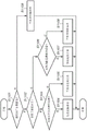
Fig. 8A and 8B are flowcharts showing an example of a processing procedure in a control method for a digital camera (communication apparatus) according to an exemplary embodiment.
Fig. 9A to 9D are diagrams showing exemplary structures of transmitting advertisement packets from a digital camera (communication apparatus) according to an exemplary embodiment.
Fig. 10 is a flowchart showing an example of a processing procedure in the control method used by the smartphone according to the exemplary embodiment.
Fig. 11 is a flowchart showing an example of a processing procedure in a control method used by a remote controller according to an exemplary embodiment.
Detailed Description
Exemplary embodiments will be described below with reference to the accompanying drawings. The following exemplary embodiment is only one example, and may be appropriately modified or changed according to each structure of the apparatus and various conditions. More specifically, although a digital camera as an image pickup apparatus is applied to a communication apparatus in the following exemplary embodiment, the communication apparatus is not limited thereto. For example, information processing apparatuses such as portable media players, tablet devices, and Personal Computers (PCs) can also be applied as communication apparatuses.
< overall structure of communication network system 10 >
Fig. 1 shows an example of the overall structure of a communication network system 10 according to a typical embodiment. As shown in fig. 1, a communication network system 10 according to the present exemplary embodiment includes a digital camera 100, a smartphone 200, and a remote controller 300.
The digital camera 100 is a communication device that wirelessly communicates with the smartphone 200 and the remote controller 300, which are other devices serving as external devices. Fig. 1 shows an example in which a digital camera 100, a smartphone 200, and a remote controller 300 perform bluetooth short-range wireless communication.
< overall structure of digital camera 100 >
Fig. 2A illustrates an example of the overall structure of the digital camera (communication apparatus) 100 illustrated in fig. 1 according to an exemplary embodiment. Fig. 2B illustrates exemplary functions of the digital camera 100 illustrated in fig. 1 that can be used with the operation of an external device. More specifically, fig. 2A shows an example of the overall structure of the digital camera 100 according to the present exemplary embodiment, and fig. 2B shows exemplary functions of the digital camera 100 according to the present exemplary embodiment that can be used with the operation of an external device.
As shown in fig. 2A, the digital camera 100 includes a control unit 101, an image capturing unit 102, a nonvolatile memory 103, a work memory 104, an operation unit 105, a display unit 106, a recording medium 107, a connection unit 108, and a short-range wireless communication unit 109.
The control unit 101 controls each component of the digital camera 100 in accordance with the input signal and a predetermined program to collectively control the operation of the digital camera 100. Instead of the control unit 101 for controlling the operation of the digital camera 100, a plurality of hardware components may share processing to control the apparatus as a whole.
The image pickup unit 102 includes, for example, an optical system for controlling an optical lens unit, an aperture stop, zooming, and focusing, and an image sensor for converting light (image) introduced via the optical lens unit into an electrical image signal. A Complementary Metal Oxide Semiconductor (CMOS) sensor or a Charge Coupled Device (CCD) sensor may be used as the image sensor. Under the control of the control unit 101, the image pickup unit 102 converts subject light (focused by a lens included in the image pickup unit 102) into an electrical signal by using an image sensor, performs noise reduction processing on the electrical signal, and outputs digital data as image data. In the digital camera 100 according to the present exemplary embodiment, the control unit 101 records image data on the recording medium 107 according to the camera file system design rule (DCF) standard.
The nonvolatile memory 103 is an electrically erasable and recordable nonvolatile memory for storing a program to be executed by the control unit 101.
The work memory 104 functions as a buffer memory for temporarily storing image data captured by the imaging unit 102, a memory for image display for the display unit 106, and a work area for the control unit 101.
The operation unit 105 is used to receive an instruction for the digital camera 100 from a user. The operation unit 105 includes switches and buttons used by the user to instruct the digital camera 100 to operate, such as a power switch for turning on and off the power, a release switch for capturing an image, a moving image capturing switch for capturing a moving image, and a reproduction button for reproducing image data. The operation unit 105 includes an operation member such as a dedicated connection button for starting communication with an external apparatus via the connection unit 108, and a touch panel formed on the display unit 106. The release switch includes SW1 and SW 2. When the release switch is half-pressed, SW1 is turned on. When the SW1 is turned on, the operation unit 105 receives instructions for image capturing preparations for performing Auto Focus (AF) processing, Auto Exposure (AE) processing, Auto White Balance (AWB) processing, and pre-flash (EF) processing. When the release switch is fully pressed, SW2 turns on. When the SW2 is turned on, the operation unit 105 receives an instruction to capture an image.
Under the control of the control unit 101, the display unit 106 displays a viewfinder image at the time of image capturing, captured image data, and text for interactive operation. The display unit 106 need not be integrated with the digital camera 100 and may be provided outside the digital camera 100. The digital camera 100 may be connected to a display unit 106 inside or outside the digital camera 100, and needs to be provided with at least a display control function for controlling display of the display unit 106.
The recording medium 107 can record image data output from the image capturing unit 102. The recording medium 107 may be detachably attached to the digital camera 100 or integrated with the digital camera 100. More specifically, the digital camera 100 needs to be provided with at least a means for accessing the recording medium 107.
The connection unit 108 is an interface for connecting with an external device. The digital camera 100 according to the present exemplary embodiment can exchange data with an external apparatus via the connection unit 108. For example, the digital camera 100 can transmit image data generated by the image capturing unit 102 to an external apparatus via the connection unit 108. According to the present exemplary embodiment, the connection unit 108 includes an interface for communicating with an external device according to the Institute of Electrical and Electronics Engineers (IEEE)802.11 standard, i.e., a wireless LAN. The control unit 101 performs wireless communication with an external device by controlling the connection unit 108. The communication method related to wireless communication is not limited to the wireless LAN, and also includes an infrared communication method.
The short-range wireless communication unit 109 is, for example, a bluetooth wireless communication unit for performing bluetooth communication. The digital camera 100 performs bluetooth communication with the smartphone 200 and the remote controller 300, which are other devices serving as external devices, via the short-range wireless communication unit 109.
When the user turns off the power switch of the operation unit 105, the digital camera 100 enters a sleep state (second operation state) that consumes less power than the normal state (first operation state). Even when the power switch of the operation unit 105 is ON, the digital camera 100 automatically enters a sleep state for power saving when the operation unit 105 is not operated. In the sleep state, in the case where the digital camera 100 performs bluetooth communication with the smart phone 200 and the remote controller 300, and when an operation request is received from the smart phone 200 or the remote controller 300, the normal state is restored from the sleep state.
For example, in the case of capturing an image using the digital camera 100 fixed on a tripod via a remote controller, the user can put the digital camera 100 in a sleep state by turning on a power switch. In this state, when the user operates the smartphone 200 or the remote controller 300 at an arbitrary timing, the digital camera 100 is restored from the sleep state to the normal state, and becomes ready to perform image capturing. When the user leaves the digital camera 100 after image capturing, the digital camera 100 automatically enters the sleep state again. The digital camera 100 enters a sleep state in this way when the user is not taking an image, thereby preventing unnecessary power consumption.
After the power switch of the digital camera 100 is turned off to place the digital camera 100 in the sleep state, the digital camera 100 may be restored from the sleep state to the normal state when the user operates the smartphone 200 in a state where, for example, the digital camera 100 is accommodated in a pocket. At this timing, the power switch of the digital camera 100 is OFF (OFF), and therefore, even if the user returns the digital camera 100 to the normal state and operates the operation unit 105, the digital camera 100 cannot capture an image. In the case where the display unit 106 does not display an image, the image may be displayed on a display unit 206 (described later) of the smartphone 200, for example, by transmitting image data recorded in the recording medium 107 to the smartphone 200. In this case, the user can view an image in the digital camera 100 by operating the smartphone 200. Since the digital camera 100 does not display an image on the display unit 106, the digital camera 100 does not consume unnecessary power. In addition, even if the user operates the operation unit 105 (for example, in the case where the digital camera 100 is operated unexpectedly in a pocket), the digital camera 100 does not capture an image.
In the digital camera 100 according to the present exemplary embodiment, operations that can be used from the external devices (the smartphone 200 and the remote controller 300) after returning from the sleep state to the normal state may be different based on the operation state of the power switch of the operation unit 105. This operation will be described below with reference to fig. 2B. As shown in fig. 2B, in the case where the operation state of the power switch is ON, the digital camera 100 (control unit 101) sets an image capturing function (first function) and an image viewing function (second function) as functions that can be used with the operation of the external apparatus in the case where the digital camera 100 is restored from the sleep state to the normal state. As shown in fig. 2B, in the case where the operation state of the power switch is OFF, the digital camera 100 (control unit 101) sets an image viewing function (second function) as a function that can be used with the operation of the external device in the case where the digital camera 100 is restored from the sleep state to the normal state.
< overall Structure of smartphone 200 >
Fig. 3 illustrates an example of the overall structure of the smartphone 200 shown in fig. 1 according to an exemplary embodiment. Although a smartphone is used as one of the external devices (other devices) in the present exemplary embodiment, the external device is not limited thereto. For example, an information processing apparatus such as a digital camera having a wireless function, a tablet apparatus, and a Personal Computer (PC) can also be applied as one of external devices (other devices).
As shown in fig. 3, the smartphone 200 includes a control unit 201, an image capturing unit 202, a nonvolatile memory 203, a work memory 204, an operation unit 205, a display unit 206, a recording medium 207, a connection unit 208, a short-range wireless communication unit 209, a public network connection unit 210, a microphone 211, and a speaker 212.
Based on the input signal and a predetermined program, the control unit 201 controls the respective components of the smartphone 200 to collectively control the operation of the smartphone 200. Instead of the control unit 201 for controlling the operation of the smartphone 200, a plurality of hardware components may share processing to control the smartphone 200 as a whole.
Under the control of the control unit 201, the image capturing unit 202 converts subject light (focused by a lens included in the image capturing unit 202) into an electrical signal, performs noise reduction processing on the electrical signal, and outputs digital data as image data. In the smartphone 200 according to the present exemplary embodiment, the control unit 201 stores image data in a buffer memory, performs predetermined calculations on the image data, and records the resultant data in the recording medium 207.
The nonvolatile memory 203 is an electrically erasable recordable nonvolatile memory for storing an operating system (OS, i.e., basic software executed by the control unit 201) and application programs for realizing applied functions in cooperation with the OS. According to the present exemplary embodiment, the nonvolatile memory 203 stores an application program for communicating with the digital camera 100.
The work memory 204 is used as a memory for image display for the display unit 206 and a work area for the control unit 201.
The operation unit 205 is used to receive an instruction for the smartphone 200 from the user. The operation unit 205 includes operation members such as a power switch for turning on and off the power of the smartphone 200 and a touch panel formed on the display unit 206.
Under the control of the control unit 201, the display unit 206 displays image data and text for interactive operation. The display unit 206 is not necessarily integrated with the smartphone 200, and may be provided outside the smartphone 200. The smartphone 200 may be connected to a display unit 206 inside or outside the smartphone 200, and needs to be provided with at least a display control function for controlling display of the display unit 206.
The recording medium 207 can record the image data output from the image capturing unit 202. The recording medium 207 may be detachably attached to the smartphone 200, or integrated with the smartphone 200. More specifically, the smartphone 200 needs to be provided with at least means for accessing the recording medium 207.
The connection unit 208 is an interface for connecting with an external device. The smartphone 200 according to the present exemplary embodiment can exchange data with the digital camera 100 via the connection unit 208. According to the present exemplary embodiment, for example, the connection unit 208 is an antenna, and the control unit 201 can establish a connection with the number via the antennaCommunication connection of the word camera 100. In the communication connection with the digital camera 100, the smartphone 200 may be directly connected with the digital camera 100 or indirectly connected with the digital camera 100 via an access point. In this case, for example, a picture transfer protocol (PTP/IP) based on the internet protocol via the wireless LAN may be used as the protocol for data communication. However, the communication connection between the smartphone 200 and the digital camera 100 is not limited thereto. For example, the connection unit 208 may include a wireless communication module such as an infrared communication module and a wireless Universal Serial Bus (USB). For the communication connection between the smartphone 200 and the digital camera 100, a high-definition multimedia interface via USB may be employed Or a cable connection of IEEE 1394.
The short-range wireless communication unit 209 is, for example, a bluetooth wireless communication unit for performing bluetooth communication. The smartphone 200 performs bluetooth communication with the digital camera 100 via the short range wireless communication unit 209. In this case, the smartphone 200 according to the present exemplary embodiment is an apparatus that performs an image capturing function (first function) and an image viewing function (second function) based on an operation by transmitting an operation request to the digital camera 100 via bluetooth communication. Then, the smartphone 200 can adopt a mode for displaying an image capture button on the display unit 206 during an image capture operation, and receiving an image from the digital camera 100 and displaying the received image on the display unit 206 during an image viewing operation.
The public network connection unit 210 is an interface for public wireless communication. The smart phone 200 makes a phone call via the public network connection unit 210. In this case, the control unit 201 makes a telephone call by inputting and outputting audio signals via the microphone 211 and the speaker 212, respectively. According to the present exemplary embodiment, for example, the public network connection unit 210 is an antenna, and the control unit 201 can be connected to the public network through the antenna. The connection unit 208 and the common network connection unit 210 may be implemented as one antenna.
< overall structure of remote controller 300 >
Fig. 4 illustrates an example of an overall structure of the remote controller 300 illustrated in fig. 1 according to an exemplary embodiment. Although the remote controller is used as one of the external devices (other devices) in the present exemplary embodiment, the external device is not limited thereto.
As shown in fig. 4, the remote controller 300 includes a control unit 301, a nonvolatile memory 302, a work memory 303, an operation unit 304, a display unit 305, and a near field wireless communication unit 306.
The control unit 301 controls each component of the remote controller 300 according to the input signal and a predetermined program to generally control the operation of the remote controller 300. Instead of the control unit 301 for controlling the operation of the remote controller 300, a plurality of hardware components may share processing to control the remote controller 300 as a whole.
The nonvolatile memory 302 is an electrically erasable and recordable nonvolatile memory for storing a program to be executed by the control unit 301.
The work memory 303 serves as a work area for the control unit 301.
The operation unit 304 is used to receive an instruction for the remote controller 300 from a user. The operation unit 304 includes operation members such as a release button for instructing the digital camera 100 to perform an image capturing operation, an AF button for instructing the digital camera 100 to perform an AF operation, and a Wide button and a Tele button for instructing the digital camera 100 to drive the zoom lens.
The display unit 305 is a display device such as a Light Emitting Diode (LED). For example, in a case where the remote controller 300 receives an operation of the operation unit 304 by a user, transmits an operation request to the digital camera 100, and then receives a response to the request, the display unit 305 displays that the digital camera 100 is operated. For example, in the case where the user operates an AF button of the operation unit 304, the remote controller 300 transmits an AF request to the digital camera 100, the digital camera 100 performs an AF operation, and then the remote controller 300 receives a focus signal from the digital camera 100 as a response, the display unit 305 blinks.
The near field wireless communication unit 306 is, for example, a bluetooth wireless communication unit for performing bluetooth communication. The remote controller 300 performs bluetooth communication with the digital camera 100 via the near field wireless communication unit 306. In this case, the remote controller 300 according to the present exemplary embodiment is an apparatus that executes an image capturing function (first function) based on an operation by transmitting an operation request to the digital camera 100 via bluetooth communication.
< sequence in which the digital camera 100 is restored from the sleep state to the normal state >
The following describes a sequence of the digital camera 100 restoring from the sleep state to the normal state in a case where the user operates the smartphone 200 or the remote controller 300 as an external device (other device) during the digital camera 100 is in the sleep state. In this case, the bluetooth communication connection between the digital camera 100 and the external device (other device) is established or disconnected. Possible cases of disconnecting the bluetooth communication connection include a case where the power of the external apparatus (other apparatus) is OFF, a case where the bluetooth function of the external apparatus (other apparatus) is disabled, and a case where the digital camera 100 is away from the external apparatus (other apparatus).
Fig. 5 shows an example of a sequence in which the digital camera (communication apparatus) 100 shown in fig. 1 is restored from a sleep state to a normal state in a case where the user operates the smartphone 200 during the sleep state of the digital camera 100. Fig. 5 shows a state in which the bluetooth communication connection between the digital camera 100 and the smartphone 200 is disconnected at the start of the sequence.
In step S501, the control unit 101 of the digital camera 100 sets the operation state of the digital camera 100 to a sleep state.
In step S502, the control unit 101 of the digital camera 100 transmits an advertisement data packet to the smartphone 200 via the short range wireless communication unit 109.
In step S503, the control unit 201 of the smartphone 200 receives the advertisement data packet transmitted via the short range wireless communication unit 209 in step S502, and confirms the content of the advertisement data packet. More specifically, in step S503, the control unit 201 of the smartphone 200 confirms whether the bluetooth communication connection is possible based on the content of the advertisement data packet. In step S503, if the control unit 201 of the smartphone 200 confirms that the bluetooth communication connection is possible (yes in step S503), the processing proceeds to step S504.
In step S504, the control unit 201 of the smartphone 200 transmits a bluetooth communication connection request to the digital camera 100 via the short-range wireless communication unit 209.
In step S505, the control unit 101 of the digital camera 100 receives the connection request transmitted in step S504 via the short-range wireless communication unit 109, and performs connection processing for bluetooth communication with the smartphone 200.
In a case where the user operates the operation unit 205 of the smartphone 200 in a state where the digital camera 100 and the smartphone 200 establish a bluetooth communication connection via this connection processing, the control unit 201 of the smartphone 200 detects this operation in step S506.
When detecting the operation in step S506, the control unit 201 of the smartphone 200 transmits an operation request to the digital camera 100 via the short-range wireless communication unit 209 in step S507.
In step S508, the control unit 101 of the digital camera 100 receives the operation request transmitted in step S507 via the short range wireless communication unit 109. Then, the control unit 101 of the digital camera 100 makes settings for restoring the operation state of the digital camera 100 from the sleep state to the normal state.
Fig. 6 shows an example of a sequence in which the digital camera (communication apparatus) 100 shown in fig. 1 is restored from a sleep state to a normal state in a case where the user operates the smartphone 200 during the sleep state of the digital camera 100. Fig. 6 shows a state in which the digital camera 100 and the smartphone 200 establish a bluetooth communication connection at the start of the sequence.
In step S601, the control unit 101 of the digital camera 100 sets the operation state of the digital camera 100 to a sleep state.
In step S602, the control unit 101 of the digital camera 100 maintains the bluetooth communication connection with the smartphone 200.
In a case where the user operates the operation unit 205 of the smartphone 200 in this connected state, the control unit 201 of the smartphone 200 detects this operation in step S603.
When detecting the operation in step S603, the control unit 201 of the smartphone 200 transmits an operation request to the digital camera 100 via the short-range wireless communication unit 209 in step S604.
In step S605, the control unit 101 of the digital camera 100 receives the operation request transmitted from the smartphone 200 in step S604 via the short-range wireless communication unit 109. Then, the control unit 101 of the digital camera 100 makes settings for restoring the operation state of the digital camera 100 from the sleep state to the normal state.
Fig. 7 shows an example of a sequence in which the digital camera (communication apparatus) 100 shown in fig. 1 is restored from a sleep state to a normal state in a case where the user operates the remote controller 300 during the sleep state of the digital camera 100. Fig. 7 shows a state in which the bluetooth communication connection between the digital camera 100 and the remote controller 300 is disconnected at the start of the sequence.
In step S701, the control unit 101 of the digital camera 100 sets the operation state of the digital camera 100 to a sleep state.
In step S702, the control unit 101 of the digital camera 100 transmits an advertisement data packet to the remote controller 300 via the short-range wireless communication unit 109.
In a case where the user operates the operation unit 304 of the remote controller 300, the control unit 301 of the remote controller 300 detects the operation in step S703.
In step S704, the control unit 301 of the remote controller 300 receives the advertisement data packet transmitted in step S702 via the near field wireless communication unit 306, and confirms the content of the advertisement data packet. More specifically, in step S704, the control unit 301 of the remote controller 300 confirms whether the bluetooth communication connection is possible based on the content of the advertisement data packet. If the control unit 301 of the remote controller 300 confirms that the bluetooth communication connection is possible (yes in step S704), the processing proceeds to step S705.
In step S705, the control unit 301 of the remote controller 300 transmits a bluetooth communication connection request to the digital camera 100 via the near field wireless communication unit 306.
In step S706, the control unit 101 of the digital camera 100 receives the connection request transmitted in step S705 via the short-range wireless communication unit 109, and performs connection processing for bluetooth communication with the remote controller 300.
In a case where the user operates the operation unit 304 of the remote controller 300 in a state where the digital camera 100 and the remote controller 300 establish the bluetooth communication connection via this connection processing, the control unit 301 of the remote controller 300 detects this operation in step S703. When the operation is detected in step S703, the control unit 301 of the remote controller 300 transmits an operation request to the digital camera 100 via the near field wireless communication unit 306 in step S707.
In step S708, the control unit 101 of the digital camera 100 receives the operation request transmitted from the remote controller 300 in step S707 via the short-range wireless communication unit 109. Then, the control unit 101 of the digital camera 100 makes settings for restoring the operation state of the digital camera 100 from the sleep state to the normal state.
In the case where the user operates the remote controller 300 in this manner as a trigger, the remote controller 300 establishes communication via the near field wireless communication unit 306, and transmits an operation request via the established communication. Then, the digital camera 100 is started.
< flow of control method of digital Camera 100 >
Fig. 8A and 8B are flowcharts showing an example of a processing procedure in the control method used by the digital camera (communication apparatus) 100 according to the exemplary embodiment. More specifically, fig. 8A and 8B show a state in which the digital camera 100 enters a sleep state.
In step S801, the control unit 101 of the digital camera 100 determines whether or not the remaining battery capacity is larger than a predetermined amount.
When the control unit 101 of the digital camera 100 determines that the remaining battery capacity is larger than the predetermined amount (yes in step S801), the processing proceeds to step S802.
In step S802, the control unit 101 of the digital camera 100 determines whether a wireless communication connection partner is set. According to the present exemplary embodiment, the case where the connection partner is set is to set the smartphone 200 or the remote controller 300 as a device in which the control unit 101 performs bluetooth communication when the user operates the operation unit 105.
According to the present exemplary embodiment, in a case where the control unit 101 of the digital camera 100 sets the smartphone 200 as a connection partner, the digital camera 100 establishes a bluetooth communication connection only with the smartphone 200. Also, according to the present exemplary embodiment, in a case where the control unit 101 of the digital camera 100 sets the remote controller 300 as a connection partner, the digital camera 100 establishes a bluetooth communication connection only with the remote controller 300. According to the present exemplary embodiment, the digital camera 100 can establish a bluetooth communication connection with an external device other than the smartphone 200 and the remote controller 300 without setting a connection partner. In this case, the digital camera 100 adopts the following mode: the digital camera 100 establishes a bluetooth communication connection with the smartphone 200 and the device that first transmits a bluetooth communication connection request among the remote controllers 300.
When the control unit 101 of the digital camera 100 determines that the wireless communication connection partner is set (yes in step S802), the processing proceeds to step S803.
In step S803, the control unit 101 of the digital camera 100 determines whether the wireless communication connection partner is the smartphone 200.
If the control unit 101 of the digital camera 100 determines that the wireless communication connection partner is the smartphone 200 (yes in step S803), the processing proceeds to step S804.
In step S804, the control unit 101 of the digital camera 100 determines whether a bluetooth communication connection is established with the smartphone 200 as a wireless communication connection partner.
If the control unit 101 of the digital camera 100 determines that a bluetooth communication connection is established with the smartphone 200 as the wireless communication connection partner (yes in step S804), the processing proceeds to step S805.
In step S805, the control unit 101 of the digital camera 100 maintains the bluetooth communication connection with the smartphone 200 as the wireless communication connection partner. Then, the process of fig. 8A ends.
If the control unit 101 of the digital camera 100 determines that the bluetooth communication connection has not been established with the smartphone 200 as the wireless communication connection partner (no in step S804), the processing proceeds to step S806.
In step S806, the control unit 101 of the digital camera 100 transmits an advertisement packet that sets the smartphone 200 as the connection partner via the short-range wireless communication unit 109. Then, the process of fig. 8A ends.
The advertisement data packet transmitted by the digital camera 100 in step S806 will be described below.
Fig. 9A to 9D show an exemplary structure of an advertisement packet transmitted from the digital camera (communication apparatus) 100 according to the exemplary embodiment to an external apparatus. For example, the control unit 101 of the digital camera 100 sets information of the connection partner in the structure of the advertisement packets 910 and 920. As shown in fig. 9A to 9D, the control unit 101 changes the value of the information of the connection partner based on whether the connection partner is the smartphone 200 or the remote controller 300 or whether the connection partner is not set.
In the case where the smartphone 200 is set as the connection partner of the digital camera 100, the control unit 101 of the digital camera 100 transmits the advertisement data packet 910 including the structure shown in fig. 9A. More specifically, in step S806 shown in fig. 8A, the control unit 101 transmits, for example, an advertisement packet 910 including the configuration shown in fig. 9A in which the smartphone 200 is set as a connection partner. In the case where the smart phone 200 receives the advertisement data packet 910 including the structure shown in fig. 9A, the smart phone 200 recognizes that the smart phone 200 is set as a connection partner of the digital camera 100 and that the bluetooth communication connection is possible based on the advertisement data packet 910. After the digital camera 100 enters the sleep state, the digital camera 100 can establish a bluetooth communication connection with the smartphone 200. In the case where the remote controller 300 receives the advertisement data packet 910 including the structure shown in fig. 9A, the remote controller 300 recognizes that the smartphone 200 is set as the connection partner of the digital camera 100 and that the bluetooth communication connection is not possible.
In the case where the power switch of the digital camera 100 is ON, the smartphone 200 is operated so that the digital camera 100 can be restored to the normal state from the sleep state, and as shown in fig. 2B, a photographing request and an image viewing request are received from the smartphone 200 after being restored to the normal state. In the case where the power switch of the digital camera 100 is OFF, the smartphone 200 is operated so that the digital camera 100 is restored from the sleep state to the normal state, and as shown in fig. 2B, an image viewing request is received from the smartphone 200 after being restored to the normal state.
Returning to the processing shown in fig. 8A, in a case where the control unit 101 of the digital camera 100 determines that the wireless communication connection partner is the remote controller 300 and not the smartphone 200 (no in step S803), the processing proceeds to step S807.
In step S807, the control unit 101 of the digital camera 100 determines whether a bluetooth communication connection is established with the remote controller 300 as a wireless communication connection partner.
In step S807, in a case where the control unit 101 of the digital camera 100 determines that the bluetooth communication connection is established with the remote controller 300 as the wireless communication connection partner (yes in step S807), the processing proceeds to step S808.
In step S808, the control unit 101 of the digital camera 100 disconnects bluetooth communication with the remote controller 300. In order to limit the power consumption of the remote controller 300, the control unit 101 disconnects the bluetooth communication when the digital camera 100 enters the sleep state.
In a case where the control unit 101 of the digital camera 100 determines that the bluetooth communication connection has not been established with the remote controller 300 (no in step S807), or in a case where the processing in step S808 is completed, the processing proceeds to step S809.
In step S809, the control unit 101 of the digital camera 100 determines whether the power switch of the operation unit 105 is ON.
In step S809, if the control unit 101 of the digital camera 100 determines that the power switch of the operation unit 105 is ON (yes in step S809), the processing proceeds to step S810.
In step S810, the control unit 101 of the digital camera 100 transmits an advertisement packet in which the remote controller 300 is set to connect to the partner via the short-range wireless communication unit 109. Then, the process of fig. 8A ends.
The advertisement data packet transmitted by the digital camera 100 in step S810 will now be explained.
In the case where the remote controller 300 is set as the connection partner of the digital camera 100, the control unit 101 of the digital camera 100 transmits the advertisement data packet 910 including the structure shown in fig. 9B. More specifically, in step S810, the control unit 101 transmits, for example, an advertisement packet 910 including a structure in which the remote controller 300 shown in fig. 9B is set to connect with the other party. In the case where the remote controller 300 receives the advertisement data packet 910 including the structure shown in fig. 9B, the remote controller 300 recognizes that the remote controller 300 is set as a connection partner of the digital camera 100 and that the bluetooth communication connection is possible based on the advertisement data packet 910. After the digital camera 100 enters the sleep state, the digital camera 100 can establish a bluetooth communication connection with the remote controller 300.
In the case where the smart phone 200 receives the advertisement data packet 910 including the structure shown in fig. 9B, the smart phone 200 recognizes that the remote controller 300 is set as the connection partner of the digital camera 100 and that the bluetooth communication connection is not possible. In the case where the power switch of the digital camera 100 is ON, the remote controller 300 is operated so that the digital camera 100 can be restored to the normal state from the sleep state, and as shown in fig. 2B, an image capturing request is received from the remote controller 300 after being restored to the normal state.
Returning to the processing shown in fig. 8A, if the control unit 101 of the digital camera 100 determines that the power switch of the operation unit 105 is not ON (i.e., the power switch is OFF) (no in step S809), the processing proceeds to step S811.
In step S811, the control unit 101 of the digital camera 100 performs processing of not transmitting an advertisement packet that sets the remote controller 300 as a connection partner. In this case, since the power switch of the operation unit 105 is OFF, the digital camera 100 cannot capture an image even when an image capturing request is received from the remote controller 300 after the recovery from the sleep state to the normal state as shown in fig. 2B. Therefore, the control unit 101 does not transmit the advertisement packet. As a result, the digital camera 100 does not establish a bluetooth communication connection with the remote controller 300. Therefore, the digital camera 100 is not restored from the sleep state to the normal state when the user operates the remote controller 300. When the processing in step S811 is completed, the processing of fig. 8A ends.
In a case where the control unit 101 of the digital camera 100 determines that the wireless communication connection partner is not set (no in step S802), the processing proceeds to step S812 in fig. 8B.
In step S812, the control unit 101 of the digital camera 100 determines whether a bluetooth communication connection is established with the smartphone 200 or the remote controller 300.
If the control unit 101 of the digital camera 100 determines that the bluetooth communication connection is established with the smartphone 200 or the remote controller 300 (yes in step S812), the processing proceeds to step S813.
In step S813, the control unit 101 of the digital camera 100 disconnects bluetooth communication.
In a case where the control unit 101 of the digital camera 100 determines that the bluetooth communication connection has not been established with the smartphone 200 or the remote controller 300 (no in step S812), or in a case where the processing in step S813 is completed, the processing proceeds to step S814.
In step S814, the control unit 101 of the digital camera 100 determines whether or not the power switch of the operation unit 105 is ON.
In step S814, if the control unit 101 of the digital camera 100 determines that the power switch of the operation unit 105 is ON (yes in step S814), the processing proceeds to step S815.
In step S815, the control unit 101 of the digital camera 100 transmits an advertisement packet in which the image capturing function and the image viewing function are set as functions that can be used with the operation of the external apparatus, via the short-range wireless communication unit 109. More specifically, in this case, the digital camera 100 notifies (informs) that the digital camera 100 supports both the image capturing function and the image viewing function. Then, the process of fig. 8B ends.
The advertisement data packet transmitted by the digital camera 100 in step S815 will be described below.
In a case where the connection partner of the digital camera 100 is not set and the image capturing function and the image viewing function are set as functions that can be used with the operation of the external apparatus, the control unit 101 of the digital camera 100 transmits the advertisement data packet 920 including the structure shown in fig. 9C. More specifically, referring to fig. 9C, the structure of the advertisement packet 920 includes a camera enable bit and a view enable bit as information ON functions that can be used with the operation of the external device, and these two bits are set to ON (1). More specifically, in step S815, the control unit 101 includes, for example, the advertisement data packet 920 shown in fig. 9C, which sets the transmission imaging function and the image viewing function to the structures of functions that can be used with the operation of the external apparatus. In the case where the smart phone 200 and the remote controller 300 receive the advertisement data packet 920 including the structure shown in fig. 9C, the smart phone 200 and the remote controller 300 recognize that the connection partner is not set in the digital camera 100, and the image capturing function and the image viewing function are usable with the operation of the external device.
In this case, since the smartphone 200 supports both the image capturing function and the image viewing function as described above and both the image capture enable bit and the viewing enable bit are ON in the advertisement data packet 920 shown in fig. 9C, the smartphone 200 recognizes that the bluetooth communication connection is possible. Since the remote controller 300 supports only the image pickup function and the image pickup enable bit is ON in the advertisement packet 920 shown in fig. 9C as described above, the remote controller 300 recognizes that the bluetooth communication connection is possible.
Returning to the processing shown in fig. 8B, if the control unit 101 of the digital camera 100 determines that the power switch of the operation unit 105 is not ON (i.e., the power switch is OFF) (no in step S814), the processing proceeds to step S816.
In step S816, the control unit 101 of the digital camera 100 transmits an advertisement packet in which the image viewing function is set as a function that can be used with the operation of the external apparatus via the short-range wireless communication unit 109. More specifically, the digital camera 100 notifies (informs) that the digital camera 100 supports only the image viewing function. Then, the process of fig. 8B ends.
The advertisement data packet transmitted by the digital camera 100 in step S816 will now be explained.
In a case where the connection partner of the digital camera 100 is not set and only the image viewing function is set as a function that can be used with the operation of the external apparatus, the control unit 101 of the digital camera 100 transmits the advertisement data packet 920 including the structure shown in fig. 9D. More specifically, referring to fig. 9D, a camera enable bit and a view enable bit are set in the structure of the advertisement data packet 920 as information ON functions that can be used with the operation of the external apparatus, and the camera enable bit is set to OFF (0) and the view enable bit is set to ON (1). More specifically, in step S816, the control unit 101 transmits the advertisement data packet 920 including a structure in which only the image viewing function is set as a function that can be used with the operation of the external apparatus shown in fig. 9D. In the case where the smart phone 200 and the remote controller 300 receive the advertisement data packet 920 including the structure shown in fig. 9D, the smart phone 200 and the remote controller 300 recognize that the connection partner is not set in the digital camera 100, and only the image viewing function can be used with the operation of the external device.
In this case, as described above, the smartphone 200 supports both the image capturing function and the image viewing function, and since the viewing enable bit is ON in the advertisement packet 920 shown in fig. 9D, the bluetooth communication connection is possible. As described above, since the remote controller 300 supports only the image pickup function (i.e., the remote controller 300 does not support the image viewing function) and only the viewing enable bit is ON in the advertisement data packet 920 shown in fig. 9D, the remote controller 300 recognizes that the bluetooth communication connection cannot be made.
The advertisement data packet 920 shown in fig. 9C and 9D represents an example of using the image capture enable bit and the view enable bit as information on functions supported by the digital camera 100. However, for example, a smartphone enable bit and a remote controller enable bit may be set. In this case, when the power switch is OFF, the smartphone enable bit may be set to ON, and the remote controller enable bit may be set to OFF. In this case, the remote controller 300 recognizes that the bluetooth communication connection with the digital camera 100 is not possible.
Returning to the processing of the flowchart of fig. 8A, in a case where the control unit 101 of the digital camera 100 determines that the remaining battery capacity is not more than the predetermined amount (i.e., the remaining battery capacity is less than or equal to the predetermined amount) (no in step S801), the processing proceeds to step S817 in fig. 8B.
In step S817, the control unit 101 of the digital camera 100 determines whether a bluetooth communication connection is established with the smartphone 200 or the remote controller 300.
If the control unit 101 of the digital camera 100 determines that a bluetooth communication connection is established with the smartphone 200 or the remote controller 300 (yes in step S817), the processing proceeds to step S818.
In step S818, the control unit 101 of the digital camera 100 disconnects bluetooth communication.
In a case where the control unit 101 of the digital camera 100 determines that the bluetooth communication connection has not been established with the smartphone 200 or the remote controller 300 (no in step S817), or in a case where the process in step S818 is completed, the process proceeds to step S819.
In step S819, the control unit 101 of the digital camera 100 performs processing of not transmitting the advertisement packet. Since the remaining battery capacity is less than or equal to the predetermined amount, the digital camera 100 cannot perform an image capturing operation even if the user operates the operation unit 105 of the digital camera 100. The digital camera 100 cannot display captured image data on the display unit 106. Therefore, even if the user operates the smartphone 200 or the remote controller 300 to restore the digital camera 100 from the sleep state to the normal state, the digital camera 100 cannot perform any operation, resulting in useless power consumption. For this reason, the digital camera 100 adopts the following mode: in the case where the remaining battery capacity is less than or equal to the predetermined amount, the control unit 101 of the digital camera 100 does not perform bluetooth communication with the smartphone 200 and the remote controller 300, and does not return the digital camera 100 from the sleep state to the normal state.
< flow of control method of smartphone 200 >
Fig. 10 is a flowchart showing an example of a processing procedure of the control method used by the smartphone 200 according to the present exemplary embodiment. More specifically, fig. 10 is a flowchart showing a process in which the smartphone 200 establishes a bluetooth communication connection with the digital camera 100 in the sleep state.
In step S1001, the control unit 201 of the smartphone 200 determines whether a bluetooth communication connection is established with the digital camera 100. If the control unit 201 of the smartphone 200 determines that a bluetooth communication connection is established with the digital camera 100 (yes in step S1001), the processing ends.
In a case where the control unit 201 of the smartphone 200 determines that the bluetooth communication connection has not been established with the digital camera 100 (no in step S1001), the processing proceeds to step S1002.
In step S1002, the control unit 201 of the smartphone 200 determines whether an advertisement data packet is received from the digital camera 100.
If the control unit 201 of the smartphone 200 determines that an advertisement packet has been received from the digital camera 100 (yes in step S1002), the processing proceeds to step S1003.
In step S1003, the control unit 201 of the smartphone 200 determines whether the wireless communication connection partner is set in the received advertisement packet.
If the control unit 201 of the smartphone 200 determines that the wireless communication connection partner is set in the received advertisement packet (yes in step S1003), the processing proceeds to step S1004.
In step S1004, the control unit 201 of the smartphone 200 determines whether the connection partner set in the received advertisement packet is the smartphone 200 itself.
In a case where the control unit 201 of the smartphone 200 determines that the connection partner set in the received advertisement packet is the smartphone 200 itself (yes in step S1004), the processing proceeds to step S1005.
In step S1005, the control unit 201 of the smartphone 200 transmits a bluetooth communication connection request to the digital camera 100 via the short-range wireless communication unit 209. Then, the process ends.
In a case where the control unit 201 of the smartphone 200 determines that the connection partner set in the received advertisement packet is not the smartphone 200 itself (no in step S1004), the processing proceeds to step S1006.
In step S1006, the control unit 201 of the smartphone 200 performs processing of not transmitting a bluetooth communication connection request to the digital camera 100. Then, the process ends.
If the control unit 201 of the smartphone 200 determines that the wireless communication connection partner is not set in the received advertisement packet (no in step S1003), the processing proceeds to step S1007.
In step S1007, the control unit 201 of the smartphone 200 determines whether or not the functions (support functions) that can be used with the operation of the external device set in the received advertisement data packet are the image capturing function and the image viewing function.
In a case where the control unit 201 of the smartphone 200 determines that the support functions set in the received advertisement packet are the image capturing function and the image viewing function (yes in step S1007), the processing proceeds to step S1008.
In step S1008, the control unit 201 of the smartphone 200 transmits a bluetooth communication connection request to the digital camera 100 via the short-range wireless communication unit 209. This is because the smartphone 200 supports both the image capturing function and the image viewing function. Then, the process ends.
In a case where the control unit 201 of the smartphone 200 determines that the support function set in the received advertisement packet is not both the image capturing function and the image viewing function (i.e., only the image viewing function is supported) (no in step S1007), the processing proceeds to step S1009.
In step S1009, the control unit 201 of the smartphone 200 transmits a bluetooth communication connection request to the digital camera 100 via the short-range wireless communication unit 209. This is because the smartphone 200 supports the image viewing function. Then, the process ends.
If the control unit 201 of the smartphone 200 determines that no advertisement data packet has been received from the digital camera 100 (no in step S1002), the processing proceeds to step S1010.
In step S1010, the control unit 201 of the smartphone 200 performs processing of not transmitting a bluetooth communication connection request to the digital camera 100. Then, the process ends.
In the flowchart shown in fig. 10, in the case where the bluetooth function of the smartphone 200 is enabled, the control unit 201 of the smartphone 200 repeats the connection process for bluetooth communication as described above.
< flow chart of control method of remote controller 300 >
Fig. 11 is a flowchart showing an example of a processing procedure in the control method used by the remote controller 300 according to the present exemplary embodiment. More specifically, fig. 11 is a flowchart showing a process in which the remote controller 300 establishes a bluetooth communication connection with the digital camera 100 in the sleep state.
In a case where the user operates the operation unit 304 of the remote controller 300, the control unit 301 of the remote controller 300 determines whether or not an advertisement data packet is received from the digital camera 100 in step S1101.
When the control unit 301 of the remote controller 300 determines that an advertisement data packet is received from the digital camera 100 (yes in step S1101), the processing proceeds to step S1102.
In step S1102, the control unit 301 of the remote controller 300 determines whether a wireless communication connection partner is set in the received advertisement packet.
In a case where the control unit 301 of the remote controller 300 determines that the wireless communication connection partner is set in the received advertisement packet (yes in step S1102), the processing proceeds to step S1103.
In step S1103, the control unit 301 of the remote controller 300 determines whether the connection partner set in the received advertisement packet is the remote controller 300 itself.
In a case where the control unit 301 of the remote controller 300 determines that the connection partner set in the received advertisement packet is the remote controller 300 itself (yes in step S1103), the processing proceeds to step S1104.
In step S1104, the control unit 301 of the remote controller 300 transmits a bluetooth communication connection request to the digital camera 100 via the near field wireless communication unit 306. Then, the process ends.
In a case where the control unit 301 of the remote controller 300 determines that the connection partner set in the received advertisement packet is not the remote controller 300 itself (no in step S1103), the processing proceeds to step S1105.
In step S1105, the control unit 301 of the remote controller 300 performs processing of not transmitting a bluetooth communication connection request to the digital camera 100. Then, the process ends.
If the control unit 301 of the remote controller 300 determines that the wireless communication connection partner is not set in the received advertisement packet (no in step S1102), the processing proceeds to step S1106.
In step S1106, the control unit 301 of the remote controller 300 determines whether or not the functions (support functions) that can be used based on the operation of the external device set in the received advertisement data packet are the image capturing function and the image viewing function.
In a case where the control unit 301 of the remote controller 300 determines that the support functions set in the received advertisement data packet are the image capturing function and the image viewing function (yes in step S1106), the processing proceeds to step S1107.
In step S1107, the control unit 301 of the remote controller 300 transmits a bluetooth communication connection request to the digital camera 100 via the near field wireless communication unit 306. This is because the remote controller 300 supports the camera function. Then, the process ends.
In a case where the control unit 301 of the remote controller 300 determines that the support function set in the received advertisement data packet is not both the image capturing function and the image viewing function (i.e., only the image viewing function is supported) (no in step S1106), the processing proceeds to step S1108.
In step S1108, the control unit 301 of the remote controller 300 performs processing of not transmitting a bluetooth communication connection request to the digital camera 100. This is because the remote controller 300 does not support the image viewing function. Then, the process ends.
If the control unit 301 of the remote controller 300 determines that no advertisement data packet has been received from the digital camera 100 (no in step S1101), the processing proceeds to step S1109.
In step S1109, the control unit 301 of the remote controller 300 performs processing of not transmitting a bluetooth communication connection request to the digital camera 100. Then, the process ends.
In the digital camera (communication apparatus) 100 according to the present exemplary embodiment, the control unit 101 sets, as an operation state of the digital camera 100, a normal state (first operation state) or a sleep state (second operation state) in which power consumption is less than in the normal state. The control unit 101 that performs this setting constitutes a first setting unit.
As shown in fig. 2B, the control unit 101 sets a function that can be used with the operation of an external device (other device) when the digital camera 100 is restored from the sleep state to the normal state, based ON the operation state (ON/OFF) of the power switch of the operation unit 105. The control unit 101 that performs this setting constitutes a second setting unit.
In the case where the other device as the object of wireless communication is a device that cannot execute the function set as shown in fig. 2B via operation, the control unit 101 controls not to perform connection processing for wireless communication with the other device (more specifically, the control unit 101 does not perform connection processing for wireless communication with the other device, that is, the control unit 101 does not transmit the advertisement packet).
The above-described structure makes it possible to prevent the digital camera (communication apparatus) 100 that performs wireless communication with other apparatuses from performing useless wireless communication with other apparatuses. For example, in the case where the operation state of the power switch of the operation unit 105 is OFF and only the image viewing function can be used as shown in fig. 2B, the control unit 101 of the digital camera 100 does not perform wireless communication with the remote controller 300 that does not support the image viewing function, thereby preventing useless wireless communication. Thus, useless power consumption can be avoided.
The above exemplary embodiments are illustrated using the following examples: as in step S811 or S819, the control unit 101 of the digital camera 100 is used to control not to transmit the advertisement packet so that wireless communication with other devices is not performed. To achieve this, for example, the following control may also be employed. More specifically, the control unit 101 of the digital camera 100 transmits an advertisement packet including information indicating that a connection for wireless communication with another apparatus cannot be made. In this case, the remote controller 300 and the smart phone 200 recognize that the connection cannot be made with reference to the information included in the advertisement packet, and thus do not transmit a connection request. For example, before step S1003 and step S1102, the smart phone 200 and the remote controller 300 respectively determine whether the advertisement packet includes information indicating that connection cannot be made. In the case where the advertisement packet includes information indicating that connection cannot be made, the smart phone 200 or the remote controller 300 does not transmit a connection request. The above-described processing enables the digital camera 100 to be controlled not to perform wireless communication with other devices.
The above-described exemplary embodiments are to be considered as illustrative, and not restrictive of the technical scope of the present invention. More specifically, the present invention may be embodied in various forms without departing from the technical concept or essential characteristics thereof.
OTHER EMBODIMENTS
The embodiments of the present invention can also be realized by a method in which software (programs) that perform the functions of the above-described embodiments are supplied to a system or an apparatus through a network or various storage media, and a computer or a Central Processing Unit (CPU), a Micro Processing Unit (MPU) of the system or the apparatus reads out and executes the methods of the programs.
While the present invention has been described with reference to exemplary embodiments, it is to be understood that the invention is not limited to the disclosed exemplary embodiments. The scope of the following claims is to be accorded the broadest interpretation so as to encompass all such modifications and equivalent structures and functions.
Claims (9)
1. A communication device, comprising:
a power source;
a power switch;
a wireless communication unit for establishing wireless communication with an external device selected from a plurality of external devices including a first external device and a second external device; and
a control unit for controlling the communication device,
wherein in a first state in which the operation state of the power switch is off, the wireless communication unit controls to establish wireless communication with the first external device and not establish wireless communication with the second external device,
wherein the wireless communication unit controls to establish wireless communication with the first external apparatus and the second external apparatus in a second state in which the operation state of the power switch is on and power supply from the power source to at least the control unit is restricted,
wherein in a third state in which the operation state of the power switch is on and the supply of electric power from the power supply to the control unit is not restricted, the wireless communication unit controls to establish wireless communication with the first external apparatus and the second external apparatus, and
wherein the communication device enters the third state in a case where an operation request is received from the selected external device in the second state.
2. The communication device of claim 1,
the control unit sets a first function and a second function different from the first function as usable functions in a case where the operation state of the power switch is on, and
the control unit sets the second function as a usable function in a case where the operation state of the power switch is off.
3. The communication apparatus according to claim 2, wherein in a case where the second function is set as the usable function, the communication apparatus controls not to establish wireless communication with the second external apparatus.
4. The communication device of claim 2, further comprising:
an image pickup unit; and
a recording medium for storing the image,
wherein the first function is an image capturing function for generating an image using the image capturing unit and recording the image in the recording medium, and
wherein the second function is a function for viewing the recorded image.
5. The communication device according to claim 1, wherein in a case where a remaining battery capacity is less than or equal to a predetermined amount in the second state, the communication device does not enter the third state even if the operation request is received from the selected external device.
6. The communication device of any of claims 1-4, wherein not establishing wireless communication comprises: the wireless communication unit does not perform connection processing for wireless communication with the selected external device.
7. The communication device of any of claims 1-4, wherein not establishing wireless communication comprises: the wireless communication unit transmits information indicating that a connection for wireless communication with the selected external device cannot be made.
8. A control method of a communication apparatus, the communication apparatus comprising: a power source; a power switch; a wireless communication unit for establishing wireless communication with an external device selected from a plurality of external devices including a first external device and a second external device; and a control unit configured to control the communication apparatus, the control method including:
controlling to establish wireless communication with the first external device and not to establish wireless communication with the second external device in a first state in which an operation state of the power switch is off;
controlling to establish wireless communication with the first external apparatus and the second external apparatus in a second state in which the operation state of the power switch is on and power supply from the power supply to at least the control unit is restricted; and
controlling to establish wireless communication with the first external apparatus and the second external apparatus in a third state in which the operation state of the power switch is on and power supply from the power supply to the control unit is not restricted,
wherein the communication device enters the third state in a case where an operation request is received from the selected external device in the second state.
9. A non-transitory computer-readable storage medium storing a program for causing a communication apparatus to execute a control method, the communication apparatus comprising: a power source; a power switch; a wireless communication unit for establishing wireless communication with an external device selected from a plurality of external devices including a first external device and a second external device; and a control unit configured to control the communication apparatus, the control method including:
controlling to establish wireless communication with the first external device and not to establish wireless communication with the second external device in a first state in which an operation state of the power switch is off;
controlling to establish wireless communication with the first external apparatus and the second external apparatus in a second state in which the operation state of the power switch is on and power supply from the power supply to at least the control unit is restricted, and
controlling to establish wireless communication with the first external apparatus and the second external apparatus in a third state in which the operation state of the power switch is on and power supply from the power supply to the control unit is not restricted,
wherein the communication device enters the third state in a case where an operation request is received from the selected external device in the second state.
Applications Claiming Priority (2)
| Application Number | Priority Date | Filing Date | Title |
|---|---|---|---|
| JP2017109336A JP6976722B2 (en) | 2017-06-01 | 2017-06-01 | Communication equipment and its control method, and programs |
| JP2017-109336 | 2017-06-01 |
Publications (2)
| Publication Number | Publication Date |
|---|---|
| CN108989543A CN108989543A (en) | 2018-12-11 |
| CN108989543B true CN108989543B (en) | 2020-12-01 |
Family
ID=64460128
Family Applications (1)
| Application Number | Title | Priority Date | Filing Date |
|---|---|---|---|
| CN201810558542.9A Active CN108989543B (en) | 2017-06-01 | 2018-06-01 | Communication apparatus, control method thereof, and storage medium |
Country Status (3)
| Country | Link |
|---|---|
| US (1) | US10645269B2 (en) |
| JP (1) | JP6976722B2 (en) |
| CN (1) | CN108989543B (en) |
Families Citing this family (1)
| Publication number | Priority date | Publication date | Assignee | Title |
|---|---|---|---|---|
| CN110365895A (en) * | 2019-06-03 | 2019-10-22 | 浙江大华技术股份有限公司 | Photographic device adjusting method, system, readable storage medium storing program for executing and equipment |
Citations (5)
| Publication number | Priority date | Publication date | Assignee | Title |
|---|---|---|---|---|
| CN103124331A (en) * | 2006-03-31 | 2013-05-29 | 奥林巴斯映像株式会社 | Information apparatus system |
| CN103685953A (en) * | 2013-12-06 | 2014-03-26 | 宇龙计算机通信科技(深圳)有限公司 | Shooting device, mobile terminal and watch |
| CN104410794A (en) * | 2014-12-23 | 2015-03-11 | 深圳市保千里电子有限公司 | Digital camera with night vision function |
| CN205283716U (en) * | 2015-12-01 | 2016-06-01 | 苏州铭冠软件科技有限公司 | Image recognition triggers data storage's device |
| CN105759686A (en) * | 2016-02-22 | 2016-07-13 | 李强 | System for controlling work of robot through APP |
Family Cites Families (15)
| Publication number | Priority date | Publication date | Assignee | Title |
|---|---|---|---|---|
| US20050046727A1 (en) * | 2003-09-02 | 2005-03-03 | Nikon Corporation | Digital camera |
| JP2006121419A (en) * | 2004-10-21 | 2006-05-11 | Nikon Corp | Camera with radio communication function |
| JP4797674B2 (en) | 2006-02-13 | 2011-10-19 | ソニー株式会社 | Information processing apparatus and method, and program |
| US7987378B2 (en) * | 2007-01-05 | 2011-07-26 | Apple Inc. | Automatic power-off of bluetooth device from linked device |
| WO2011111157A1 (en) * | 2010-03-09 | 2011-09-15 | キヤノン株式会社 | Video display apparatus, method of controlling video display apparatus, video output apparatus, and method of controlling video output apparatus |
| CN103092306B (en) * | 2011-11-04 | 2016-07-06 | 联想(北京)有限公司 | Messaging device and power-supply switching method |
| US10135494B2 (en) * | 2011-12-16 | 2018-11-20 | Intel Corporation | Connection and synchronization with a device in a non-active state based on near field communication |
| US8934045B2 (en) * | 2012-03-12 | 2015-01-13 | Apple Inc. | Digital camera system having remote control |
| CN103856604A (en) * | 2012-11-29 | 2014-06-11 | 华移联科(沈阳)技术有限公司 | Multimedia terminal easy for operation |
| JP5527492B1 (en) * | 2013-08-19 | 2014-06-18 | ソニー株式会社 | Imaging apparatus, control method, and program |
| JP6257336B2 (en) * | 2014-01-14 | 2018-01-10 | キヤノン株式会社 | IMAGING DEVICE AND IMAGING DEVICE CONTROL METHOD |
| JP6292913B2 (en) | 2014-02-10 | 2018-03-14 | キヤノン株式会社 | Communication device, control method thereof and program |
| CN105069862B (en) * | 2015-08-13 | 2018-04-06 | 深圳市爱乐士电子有限公司 | Drive recorder and its control method are not powered off |
| CN105872391A (en) * | 2016-06-15 | 2016-08-17 | 华为技术有限公司 | Control method, control device and control system for IP (Internet Protocol) Camera |
| TWI603619B (en) * | 2016-07-25 | 2017-10-21 | A low power consumption and fast response and low false alarm rate of the video surveillance system |
-
2017
- 2017-06-01 JP JP2017109336A patent/JP6976722B2/en active Active
-
2018
- 2018-05-25 US US15/990,470 patent/US10645269B2/en active Active
- 2018-06-01 CN CN201810558542.9A patent/CN108989543B/en active Active
Patent Citations (5)
| Publication number | Priority date | Publication date | Assignee | Title |
|---|---|---|---|---|
| CN103124331A (en) * | 2006-03-31 | 2013-05-29 | 奥林巴斯映像株式会社 | Information apparatus system |
| CN103685953A (en) * | 2013-12-06 | 2014-03-26 | 宇龙计算机通信科技(深圳)有限公司 | Shooting device, mobile terminal and watch |
| CN104410794A (en) * | 2014-12-23 | 2015-03-11 | 深圳市保千里电子有限公司 | Digital camera with night vision function |
| CN205283716U (en) * | 2015-12-01 | 2016-06-01 | 苏州铭冠软件科技有限公司 | Image recognition triggers data storage's device |
| CN105759686A (en) * | 2016-02-22 | 2016-07-13 | 李强 | System for controlling work of robot through APP |
Also Published As
| Publication number | Publication date |
|---|---|
| JP6976722B2 (en) | 2021-12-08 |
| US20180352136A1 (en) | 2018-12-06 |
| US10645269B2 (en) | 2020-05-05 |
| CN108989543A (en) | 2018-12-11 |
| JP2018207256A (en) | 2018-12-27 |
Similar Documents
| Publication | Publication Date | Title |
|---|---|---|
| CN110035420B (en) | Communication system and apparatus, image capturing apparatus, control method, and storage medium | |
| US11082600B2 (en) | Electronic apparatus that performs wireless communication with an image capturing device at two different communication speeds, and method for controlling same | |
| JP6858069B2 (en) | Image supply device and information processing device and their control methods and programs | |
| JP6433265B2 (en) | Information processing apparatus, electronic device, control method thereof, program, and storage medium | |
| JP6821360B2 (en) | Electronic devices and their control methods | |
| JP6682365B2 (en) | COMMUNICATION DEVICE, COMMUNICATION DEVICE CONTROL METHOD, AND PROGRAM | |
| JP6385078B2 (en) | COMMUNICATION DEVICE, COMMUNICATION DEVICE CONTROL METHOD, PROGRAM | |
| CN108989543B (en) | Communication apparatus, control method thereof, and storage medium | |
| JP2018136630A (en) | Communication apparatus, image capturing apparatus, control method, and program | |
| JP4574077B2 (en) | COMMUNICATION SYSTEM, RADIO COMMUNICATION DEVICE, AND IMAGING DEVICE | |
| US10986247B2 (en) | Communication apparatus, data transfer apparatus, and methods of controlling them | |
| JP6700821B2 (en) | Communication device, imaging device, control method thereof, and program | |
| JP6478615B2 (en) | COMMUNICATION DEVICE, ITS CONTROL METHOD, AND PROGRAM | |
| JP6468827B2 (en) | IMAGING DEVICE, IMAGING DEVICE CONTROL METHOD, PROGRAM | |
| JP2019004422A (en) | Communication device, control method, and program | |
| US11503656B2 (en) | Communication apparatus, method for controlling communication apparatus, and storage medium | |
| JP6783640B2 (en) | Communication device, control method of communication device, program | |
| JP6746428B2 (en) | IMAGING DEVICE, IMAGING DEVICE CONTROL METHOD, AND PROGRAM | |
| JP2017216640A (en) | Imaging device, control method of imaging device, and program | |
| JP2016100724A (en) | Information processing device, information processing method, and program | |
| JP2016122952A (en) | Connection method of digital camera and cellular phone | |
| JP2024015828A (en) | Imaging device, its control method, program, storage medium | |
| JP2019087956A (en) | Image shooting apparatus, control method of image shooting apparatus, and program | |
| JP2019004390A (en) | Imaging device, communication device, control method, and program | |
| JP2019148863A (en) | Information processing device, information processing method and program |
Legal Events
| Date | Code | Title | Description |
|---|---|---|---|
| PB01 | Publication | ||
| PB01 | Publication | ||
| SE01 | Entry into force of request for substantive examination | ||
| SE01 | Entry into force of request for substantive examination | ||
| GR01 | Patent grant | ||
| GR01 | Patent grant |