JP6858069B2 - Image supply device and information processing device and their control methods and programs - Google Patents
Image supply device and information processing device and their control methods and programs Download PDFInfo
- Publication number
- JP6858069B2 JP6858069B2 JP2017091945A JP2017091945A JP6858069B2 JP 6858069 B2 JP6858069 B2 JP 6858069B2 JP 2017091945 A JP2017091945 A JP 2017091945A JP 2017091945 A JP2017091945 A JP 2017091945A JP 6858069 B2 JP6858069 B2 JP 6858069B2
- Authority
- JP
- Japan
- Prior art keywords
- image
- request
- supply device
- response
- communication
- Prior art date
- Legal status (The legal status is an assumption and is not a legal conclusion. Google has not performed a legal analysis and makes no representation as to the accuracy of the status listed.)
- Active
Links
Images


Classifications
-
- G—PHYSICS
- G06—COMPUTING; CALCULATING OR COUNTING
- G06F—ELECTRIC DIGITAL DATA PROCESSING
- G06F16/00—Information retrieval; Database structures therefor; File system structures therefor
- G06F16/50—Information retrieval; Database structures therefor; File system structures therefor of still image data
- G06F16/54—Browsing; Visualisation therefor
-
- G—PHYSICS
- G06—COMPUTING; CALCULATING OR COUNTING
- G06F—ELECTRIC DIGITAL DATA PROCESSING
- G06F16/00—Information retrieval; Database structures therefor; File system structures therefor
- G06F16/50—Information retrieval; Database structures therefor; File system structures therefor of still image data
- G06F16/58—Retrieval characterised by using metadata, e.g. metadata not derived from the content or metadata generated manually
- G06F16/5866—Retrieval characterised by using metadata, e.g. metadata not derived from the content or metadata generated manually using information manually generated, e.g. tags, keywords, comments, manually generated location and time information
-
- G—PHYSICS
- G06—COMPUTING; CALCULATING OR COUNTING
- G06F—ELECTRIC DIGITAL DATA PROCESSING
- G06F3/00—Input arrangements for transferring data to be processed into a form capable of being handled by the computer; Output arrangements for transferring data from processing unit to output unit, e.g. interface arrangements
- G06F3/01—Input arrangements or combined input and output arrangements for interaction between user and computer
- G06F3/048—Interaction techniques based on graphical user interfaces [GUI]
- G06F3/0481—Interaction techniques based on graphical user interfaces [GUI] based on specific properties of the displayed interaction object or a metaphor-based environment, e.g. interaction with desktop elements like windows or icons, or assisted by a cursor's changing behaviour or appearance
- G06F3/0482—Interaction with lists of selectable items, e.g. menus
-
- H—ELECTRICITY
- H04—ELECTRIC COMMUNICATION TECHNIQUE
- H04L—TRANSMISSION OF DIGITAL INFORMATION, e.g. TELEGRAPHIC COMMUNICATION
- H04L67/00—Network arrangements or protocols for supporting network services or applications
- H04L67/01—Protocols
-
- H—ELECTRICITY
- H04—ELECTRIC COMMUNICATION TECHNIQUE
- H04L—TRANSMISSION OF DIGITAL INFORMATION, e.g. TELEGRAPHIC COMMUNICATION
- H04L67/00—Network arrangements or protocols for supporting network services or applications
- H04L67/01—Protocols
- H04L67/02—Protocols based on web technology, e.g. hypertext transfer protocol [HTTP]
-
- H—ELECTRICITY
- H04—ELECTRIC COMMUNICATION TECHNIQUE
- H04L—TRANSMISSION OF DIGITAL INFORMATION, e.g. TELEGRAPHIC COMMUNICATION
- H04L67/00—Network arrangements or protocols for supporting network services or applications
- H04L67/01—Protocols
- H04L67/04—Protocols specially adapted for terminals or networks with limited capabilities; specially adapted for terminal portability
-
- H—ELECTRICITY
- H04—ELECTRIC COMMUNICATION TECHNIQUE
- H04L—TRANSMISSION OF DIGITAL INFORMATION, e.g. TELEGRAPHIC COMMUNICATION
- H04L67/00—Network arrangements or protocols for supporting network services or applications
- H04L67/01—Protocols
- H04L67/12—Protocols specially adapted for proprietary or special-purpose networking environments, e.g. medical networks, sensor networks, networks in vehicles or remote metering networks
- H04L67/125—Protocols specially adapted for proprietary or special-purpose networking environments, e.g. medical networks, sensor networks, networks in vehicles or remote metering networks involving control of end-device applications over a network
Description
本発明は、画像供給装置及び情報処理装置及びそれらの制御方法とプログラムに関するものである。 The present invention relates to an image supply device and an information processing device, and control methods and programs thereof.
近年、デジタルカメラと携帯電話とが無線で接続し、デジタルカメラの機能を携帯電話から利用することが行われている。例えば特許文献1には、デジタルカメラと携帯電話とが無線LANを介して接続し、携帯電話を操作することでデジタルカメラに記録されている画像をリモートで閲覧するシステムが開示されている。 In recent years, a digital camera and a mobile phone are wirelessly connected, and the function of the digital camera is used from the mobile phone. For example, Patent Document 1 discloses a system in which a digital camera and a mobile phone are connected via a wireless LAN, and an image recorded on the digital camera is remotely browsed by operating the mobile phone.
しかしながら、HTTP(Hypertext Transfer Protocol)のようなクライアントサーバ型のシステムを実現する通信プロトコルを用いた場合、サーバ機器で選択した画像をクライアント機器に送信することができない。 However, when a communication protocol that realizes a client-server type system such as HTTP (Hypertext Transfer Protocol) is used, the image selected by the server device cannot be transmitted to the client device.
本発明は、クライアントサーバ型のシステムを実現する通信プロトコルにおいて、サーバ機器で選択した画像をクライアント機器に送信する技術を提供しようとするものである。 The present invention is an object of the present invention to provide a technique for transmitting an image selected by a server device to a client device in a communication protocol that realizes a client-server type system.
この課題を解決するため、例えば本発明の画像供給装置は以下の構成を備わる。すなわち、
クライアントからの要求に応じて画像を送信する画像供給装置であって、
画像を記憶する記憶手段と、
リクエスト/レスポンス型の通信プロトコルを用いて通信を行う通信手段と、
前記通信手段を介して受信したクライアントからの要求の種類に応じた処理を行い、前記通信手段を介して応答を返す処理手段と、を有し、
前記処理手段は、
所定の要求を受信した場合、前記所定の要求に対する応答を送信する前に、前記記憶手段に記憶されている画像の一覧を、ユーザが選択可能なユーザインターフェースとして表示する表示手段と、
前記ユーザインターフェースを介してユーザが画像を選択した場合、前記クライアントが前記選択した画像の送信要求を行えるようにするため、前記選択した画像を特定する情報を生成する生成手段と、
前記生成手段が生成した情報を前記所定の要求に対する応答として前記クライアントに送信する送信手段とを有する。
In order to solve this problem, for example, the image supply device of the present invention has the following configuration. That is,
An image supply device that transmits images in response to requests from clients.
A storage means for storing images and
A communication means that communicates using a request / response type communication protocol,
It has a processing means that performs processing according to the type of request from a client received via the communication means and returns a response via the communication means.
The processing means
When a predetermined request is received, a display means for displaying a list of images stored in the storage means as a user interface that can be selected by the user before transmitting a response to the predetermined request, and a display means.
When a user selects an image via the user interface, a generation means for generating information that identifies the selected image and a generation means for generating information that identifies the selected image so that the client can make a transmission request for the selected image.
It has a transmission means for transmitting the information generated by the generation means to the client as a response to the predetermined request.
本発明によれば、クライアントサーバ型のプロトコルにおいて、サーバ側にてユーザが選択した画像をクライアントに送信することが可能になる。 According to the present invention, in a client-server protocol, an image selected by a user on the server side can be transmitted to a client.
以下に、本発明を実施するための形態について、添付の図面を用いて詳細に説明する。なお、以下に説明する実施の形態は、本発明の実現手段としての一例であり、本発明が適用される装置の構成や各種条件によって適宜修正又は変更されてもよい。また、各実施の形態を適宜組み合せることも可能である。 Hereinafter, embodiments for carrying out the present invention will be described in detail with reference to the accompanying drawings. The embodiment described below is an example as a means for realizing the present invention, and may be appropriately modified or changed depending on the configuration of the device to which the present invention is applied and various conditions. It is also possible to combine each embodiment as appropriate.
[第1の実施形態]
<デジタルカメラ100の内部構成>
図1は、本実施形態のサーバ側の画像供給装置として機能するデジタルカメラ100の構成例を示すブロック図である。なお、ここでは画像供給装置の一例としてデジタルカメラについて述べるが、これに限られない。例えば携帯型のメディアプレーヤや、いわゆるタブレットデバイス、パーソナルコンピュータなどの通信装置であっても構わない。
[First Embodiment]
<Internal configuration of
FIG. 1 is a block diagram showing a configuration example of a
制御部101はプロセッサ(CPU)を含み、入力された信号や、後述のプログラムに従ってデジタルカメラ100の各部を制御する。なお、制御部101が装置全体を制御する代わりに、複数のハードウェアが処理を分担することで、装置全体を制御してもよい。
The
撮像部102は、例えば、光学レンズユニットと絞り・ズーム・フォーカスなど制御する光学系と、光学レンズユニットを経て導入された光(映像)を電気的な映像信号に変換するための撮像素子などで構成される。撮像素子としては、一般的には、CMOS(Complementary Metal Oxide Semiconductor)や、CCD(Charge Coupled Device)が利用される。撮像部102は、制御部101に制御されることにより、撮像部102に含まれるレンズで結像された被写体光を、撮像素子により電気信号に変換し、ノイズ低減処理などを行いデジタルデータを画像データとして出力する。本実施形態のデジタルカメラ100では、画像データは、DCF(Design Rule for Camera File system)の規格に従って、記録媒体110に記録される。
The
不揮発性メモリ103は、電気的に消去・記録可能な不揮発性のメモリであり、制御部101で実行される後述のプログラム等が格納される。作業用メモリ104は、撮像部102で撮像された画像データを一時的に保持するバッファメモリや、表示部106の画像表示用メモリ、制御部101の作業領域等として使用される。
The
操作部105は、ユーザがデジタルカメラ100に対する指示をユーザから受け付けるために用いられる。操作部105は例えば、ユーザがデジタルカメラ100の電源のON/OFFを指示するための電源ボタンや、撮影を指示するためのレリーズスイッチ、画像データの再生を指示するための再生ボタンを含む。さらに、後述の接続部111を介して外部機器との通信を開始するための専用の接続ボタンなどの操作部材を含む。また、後述する表示部106に形成されるタッチパネルも操作部105に含まれる。なお、レリーズスイッチは、SW1およびSW2を有する。レリーズスイッチが、いわゆる半押し状態となることにより、SW1がONとなる。これにより、AF(オートフォーカス)処理、AE(自動露出)処理、AWB(オートホワイトバランス)処理、EF(フラッシュプリ発光)処理等の撮影準備を行うための指示を受け付ける。また、レリーズスイッチが、いわゆる全押し状態となることにより、SW2がONとなる。これにより、撮影を行うための指示を受け付ける。
The
表示部106は、撮影の際のビューファインダー画像の表示、撮影した画像データの表示、対話的な操作のための文字表示などを行う。なお、表示部106は必ずしもデジタルカメラ100に内蔵する必要はない。デジタルカメラ100は内部又は外部の表示部106と接続することができ、表示部106の表示を制御する表示制御機能を少なくとも有していればよい。
The display unit 106 displays a viewfinder image at the time of shooting, displays captured image data, displays characters for interactive operation, and the like. The display unit 106 does not necessarily have to be built in the
記録媒体110は、撮像部102から出力された画像データを記録することができる。記録媒体110は、デジタルカメラ100に着脱可能なよう構成してもよいし、デジタルカメラ100に内蔵されていてもよい。すなわち、デジタルカメラ100は少なくとも記録媒体110にアクセスする手段を有していればよい。
The
接続部111は、外部装置と接続するためのインターフェースである。本実施形態のデジタルカメラ100は、接続部111を介して、外部装置とデータのやりとりを行うことができる。例えば、撮像部102で生成した画像データを、接続部111を介して外部装置に送信することができる。なお、本実施形態では、接続部111は外部装置とIEEE802.11の規格に従った、いわゆる無線LANで通信するためのインターフェースを含む。制御部101は、接続部111を制御することで外部装置との無線通信を実現する。なお、通信方式は無線LANに限定されるものではなく、例えば赤外通信方式も含む。接続部111は第1の無線通信手段の一例である。
The
近距離無線通信部112は、例えば無線通信のためのアンテナと無線信号を処理するため変復調回路や通信コントローラから構成される。近距離無線通信部112は、変調した無線信号をアンテナから出力し、またアンテナで受信した無線信号を復調することによりIEEE802.15の規格(いわゆるBluetooth(登録商標))に従った近距離無線通信を実現する。本実施形態においてBluetooth(登録商標)通信は、低消費電力であるBluetooth(登録商標) Low Energyのバージョン4.0を採用する。このBluetooth(登録商標)通信は、無線LAN通信と比べて通信可能な範囲が狭い(つまり、通信可能な距離が短い)。また、Bluetooth(登録商標)通信は、無線LAN通信と比べて通信速度が遅い。その一方で、Bluetooth(登録商標)通信は、無線LAN通信と比べて消費電力が少ない。本実施形態のデジタルカメラ100は、近距離無線通信部112を介して、外部装置とデータのやりとりを行うことができる。例えば外部装置から撮影の命令を受信した場合は撮像部102を制御し、撮影動作を行い、無線LAN通信によるデータの授受を行うための命令を受信した場合は接続部111を制御し、無線LAN通信を開始する。
The short-range
近接無線通信部113は、例えば無線通信のためのアンテナと無線信号を処理するため変復調回路や通信コントローラから構成される。近接無線通信部113は、変調した無線信号をアンテナから出力し、またアンテナで受信した無線信号を復調することでISO/IEC 18092の規格(いわゆるNFC:Near Field Communication)に従った非接触近接通信を実現する。本実施形態の近接無線通信部113は、デジタルカメラ100の側部に配される。
The proximity
スマートデバイス200とは、互いの近接無線通信部を近接させることにより通信を開始して接続される。なお、近接無線通信部を用いて接続させる場合、必ずしも近接無線通信部同士を接触させる必要はない。近接無線通信部は一定の距離だけ離れていても通信することができるため、互いの機器を接続するためには、近接無線通信可能な範囲まで近づければよい。以下の説明では、この近接無線通信可能な範囲まで近づけることを、近接させる、とも記載する。
The
また、互いの近接無線通信部が近接無線通信不可能な範囲にあれば、通信は開始されない。また、互いの近接無線通信部が近接無線通信可能な範囲にあって、デジタルカメラ100同士が通信接続されている際に、互いの近接無線通信部113が近接無線通信不可能な範囲に離れてしまった場合は、通信接続が解除される。なお、近接無線通信部113が実現する非接触近接通信はNFCに限られるものではなく、他の無線通信を採用してもよい。例えば、近接無線通信部113が実現する非接触近接通信として、ISO/IEC 14443の規格に従った非接触近接通信を採用してもよい。
Further, if the proximity wireless communication units of each other are within the range where the proximity wireless communication is impossible, the communication is not started. Further, when the close radio communication units of each other are in the range where the close radio communication is possible and the
本実施形態では、接続部111により実現される通信の通信速度は、後述の近接無線通信部113により実現される通信の通信速度よりも速い。また、接続部111により実現される通信は、近接無線通信部113による通信よりも、通信可能な範囲が広い。その代わり、近接無線通信部113による通信では、通信可能な範囲の狭さにより通信相手を限定することができるため、接続部111により実現される通信で必要な暗号鍵の交換等の処理を必要としない。すなわち、接続部111を用いるよりも手軽に通信することができる。
In the present embodiment, the communication speed of the communication realized by the
なお、本実施形態におけるデジタルカメラ100の接続部111は、インフラストラクチャモードにおけるアクセスポイントとして動作するAPモードと、インフラストラクチャモードにおけるクライアントとして動作するCLモードとを有している。そして、接続部111をCLモードで動作させることにより、本実施形態におけるデジタルカメラ100は、インフラストラクチャモードにおけるCL機器として動作することが可能である。デジタルカメラ100がCL機器として動作する場合、周辺のAP機器に接続することで、AP機器が形成するネットワークに参加することが可能である。また、接続部111をAPモードで動作させることにより、本実施形態におけるデジタルカメラ100は、APの一種ではあるが、より機能が限定された簡易的なAP(以下、簡易AP)として動作することも可能である。デジタルカメラ100が簡易APとして動作すると、デジタルカメラ100は自身でネットワークを形成する。デジタルカメラ100の周辺の装置は、デジタルカメラ100をAP機器と認識し、デジタルカメラ100が形成したネットワークに参加することが可能となる。上記のようにデジタルカメラ100を動作させるためのプログラムは不揮発性メモリ103に保持されているものとする。
The
なお、本実施形態におけるデジタルカメラ100はAPの一種であるものの、CL機器から受信したデータをインターネットプロバイダなどに転送するゲートウェイ機能は有していない簡易APである。したがって、自機が形成したネットワークに参加している他の装置からデータを受信しても、それをインターネットなどのネットワークに転送することはできない。以上が実施形態におけるデジタルカメラ100の説明である。
Although the
<スマートデバイス200の内部構成>
図2は、本実施形態の情報処理装置の一例であるスマートデバイス200の構成例を示すブロック図である。なお、ここでは情報処理装置の一例としてスマートデバイスについて述べるが、情報処理装置はこれに限られない。例えば情報処理装置は、無線機能付きのデジタルカメラ、タブレットデバイス、あるいはパーソナルコンピュータなどであってもよい。
<Internal configuration of
FIG. 2 is a block diagram showing a configuration example of a
制御部201はプロセッサ(CPU)を含み、入力された信号や、後述のプログラムに従ってスマートデバイス200の各部を制御する。なお、制御部201が装置全体を制御する代わりに、複数のハードウェアが処理を分担することで、装置全体を制御してもよい。
The
撮像部202は、撮像部202に含まれるレンズで結像された被写体光を電気信号に変換し、ノイズ低減処理などを行いデジタルデータを画像データとして出力する。撮像した画像データはバッファメモリに蓄えられた後、制御部201にて所定の演算を行い、記録媒体210に記録される。
The
不揮発性メモリ203は、電気的に消去・記録可能な不揮発性のメモリである。不揮発性メモリ203には、制御部201が実行する基本的なソフトウェアであるOS(オペレーティングシステム)や、このOSと協働して応用的な機能を実現するアプリケーションが記録されている。また、本実施形態では、不揮発性メモリ203には、デジタルカメラ100と通信するためのアプリケーション(以下アプリ)が格納されている。
The
作業用メモリ204は、表示部206の画像表示用メモリや、制御部201の作業領域等として使用される。操作部205は、スマートデバイス200に対する指示をユーザから受け付けるために用いられる。操作部205は例えば、ユーザがスマートデバイス200の電源のON/OFFを指示するための電源ボタンや、表示部206に形成されるタッチパネルなどの操作部材を含む。
The
表示部206は、画像データの表示、対話的な操作のための文字表示などを行う。なお、表示部206は必ずしもスマートデバイス200が備える必要はない。スマートデバイス200は表示部206と接続することができ、表示部206の表示を制御する表示制御機能を少なくとも有していればよい。
The
記録媒体210は、撮像部202から出力された画像データを記録することができる。記録媒体210は、スマートデバイス200に着脱可能なよう構成してもよいし、スマートデバイス200に内蔵されていてもよい。すなわち、スマートデバイス200は少なくとも記録媒体210にアクセスする手段を有していればよい。
The
接続部211は、外部装置と接続するためのインターフェースである。本実施形態のスマートデバイス200は、接続部211を介して、デジタルカメラ100とデータのやりとりを行うことができる。本実施形態では、接続部211はアンテナであり、制御部201は、アンテナを介して、デジタルカメラ100と接続することができる。なお、デジタルカメラ100との接続では、直接接続してもよいしアクセスポイントを介して接続してもよい。データを通信するためのプロトコルとしては、例えば無線LANを通じたPTP/IP(Picture Transfer Protocol over Internet Protocol)を用いることができる。なお、デジタルカメラ100との通信はこれに限られるものではない。例えば、接続部211は、赤外線通信モジュール、WirelessUSB等の無線通信モジュールを含むことができる。さらには、USBケーブルやHDMI、IEEE1394など、有線接続を採用してもよい。
The
公衆網接続部213は、公衆無線通信を行う際に用いられるインターフェースである。スマートデバイス200は、公衆網接続部213を介して、他の機器と通話することができる。この際、制御部201はマイク214およびスピーカ215を介して音声信号の入力と出力を行うことで、通話を実現する。本実施形態では、公衆網接続部213はアンテナであり、制御部201は、アンテナを介して、公衆網に接続することができる。なお、接続部211および公衆網接続部213は、一つのアンテナで兼用することも可能である。
The public
近距離無線通信部216は、例えば無線通信のためのアンテナと無線信号を処理するため変復調回路や通信コントローラから構成される。近距離無線通信部216は、変調した無線信号をアンテナから出力し、またアンテナで受信した無線信号を復調することによりIEEE802.15の規格(いわゆるBluetooth(登録商標))に従った近距離無線通信を実現する。本実施形態においてBluetooth(登録商標)通信は、低消費電力であるBluetooth(登録商標) Low Energyのバージョン4.0(BLE)を採用する。このBluetooth(登録商標)通信は、無線LAN通信と比べて通信可能な範囲が狭い(つまり、通信可能な距離が短い)。また、Bluetooth(登録商標)通信は、無線LAN通信と比べて通信速度が遅い。その一方で、Bluetooth(登録商標)通信は、無線LAN通信と比べて消費電力が少ない。
The short-range
近接無線通信部217は、他機との非接触近接通信を実現するための通信ユニットである。近接無線通信部217は、無線通信のためのアンテナと無線信号を処理するための変復調回路や通信コントローラから構成される。近接無線通信部217は、変調した無線信号をアンテナから出力し、またアンテナで受信した無線信号を復調することにより非接触近接通信を実現する。ここでは、ISO/IEC 18092の規格(いわゆるNFC)に従った非接触通信を実現する。近接無線通信部217は、他のデバイスからデータ読み出し要求を受けると、不揮発性メモリ203に格納されているデータに基づき、応答データを出力する。本実施形態では、スマートデバイス200は、近接無線通信部217を通じて、NFCの規格で定義されているカードリーダモード、カードライタモードおよびP2Pモードで動作し、主にInitiatorとしてふるまう。対して、デジタルカメラ100は近接無線通信部112を介して、主にTargetとしてふるまう。以上がスマートデバイス200の説明である。
The proximity
<送信モード>
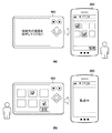
図3(a),(b)はそれぞれ異なる送信モードを説明するためのイメージ図である。各送信モードにおいて、デジタルカメラら100がサーバとして機能した場合における、デジタルカメラ100に保存されているファイルを、クライアント機器として機能するスマートデバイス200に送信する際の送信方法の違いを説明する。
<Transmission mode>
3A and 3B are image diagrams for explaining different transmission modes. In each transmission mode, when the digital cameras and the like 100 function as a server, the difference in the transmission method when transmitting the file stored in the
図3(a)は送信モードがプル送信の場合のイメージ図である。プル送信では、クライアント機器(スマートデバイス200)にて、ユーザが画像の選択を行うためのユーザインターフェースが表示され、ユーザがその中から送信対象のファイルを選択する。クライアント機器はサーバ機器に対してファイルを要求し、サーバ機器は要求されたファイルをクライアント機器に送信する。 FIG. 3A is an image diagram when the transmission mode is pull transmission. In the pull transmission, the client device (smart device 200) displays a user interface for the user to select an image, and the user selects a file to be transmitted from the user interface. The client device requests a file from the server device, and the server device sends the requested file to the client device.
図3(b)は送信モードがプッシュ送信の場合のイメージ図である。プッシュ送信では、サーバ機器(デジタルカメラ100)にて、ユーザが画像の選択を行うためのユーザインターフェースを表示し、ユーザがその中から送信対象のファイルを選択する。選択が完了すると、サーバ機器は選択されたファイルの送信を行う。 FIG. 3B is an image diagram when the transmission mode is push transmission. In push transmission, the server device (digital camera 100) displays a user interface for the user to select an image, and the user selects a file to be transmitted from the user interface. When the selection is complete, the server device sends the selected file.
ここで、HTTPのようなリクエスト/レスポンス型の通信プロトコルを用いる場合、サーバ機器であるデジタルカメラ100からクライアント機器であるスマートデバイス200へ、選択した画像を自発的に送信することができない。この問題を解消するためには、何らかの方法でサーバ側からの自発的な送信(サーバプッシュ)を実現する必要がある。
Here, when a request / response type communication protocol such as HTTP is used, the selected image cannot be spontaneously transmitted from the
そこで本実施形態では、ロングポーリングという技術を用いて、擬似的なサーバプッシュを実現する。ロングポーリングでは、まずクライアント機器からリクエストを送信し、サーバはあえてそのリクエストに対するレスポンスを保留しておく。そしてサーバは何らかのデータ通信を行うための任意のタイミングで、保留していたリクエストに対するレスポンスを送信する。このようにすることで、任意のタイミングでサーバからクライアントにデータを送信する、いわゆるサーバプッシュを擬似的に実現できる。 Therefore, in the present embodiment, a pseudo server push is realized by using a technique called long polling. In long polling, the client device first sends a request, and the server dares to suspend the response to the request. Then, the server sends a response to the pending request at an arbitrary timing for performing some data communication. By doing so, it is possible to realize a so-called server push in which data is transmitted from the server to the client at an arbitrary timing.
以下、具体的な動作について説明する。本実施形態では、既に説明したように、デジタルカメラ100をサーバ、スマートデバイス200をクライアントとして説明する。
The specific operation will be described below. In the present embodiment, as described above, the
図4、図5を参照して、デジタルカメラ100を操作してスマートデバイス200へ画像をプッシュ送信する際の処理の流れについて説明する。
The flow of processing when the
図4は、デジタルカメラ100からスマートデバイス200へ画像をプッシュ送信する際のシーケンス図である。
FIG. 4 is a sequence diagram when an image is pushed and transmitted from the
図5は、デジタルカメラ100とスマートデバイス200における画面の例を示した図である。
FIG. 5 is a diagram showing an example of screens in the
まず、ステップS401において、デジタルカメラ100とスマートデバイス200は、接続部111、211を用いてWi−Fi接続を行い、機器発見プロトコルによりお互いのデバイスを発見し、データ通信を行うためのプロトコル接続をすることにより機器同士の接続が完了する。データ通信を行うためのプロトコルとして、例えば、HTTPがあげられる。本実施形態では、デジタルカメラ100がHTTPサーバ、スマートデバイス200がHTTPクライアントとして動作する点に注意されたい。
First, in step S401, the
次に、ステップS402において、クライアントであるスマートデバイス200は、デジタルカメラ100に対して、ロングポーリングリクエストを送信する。ロングポーリングリクエストを通常のリクエストを区別するためには、例えばリクエストコマンドに特定の引数やフラグを付与したり、別のリクエストコマンドを用意したりすることが考えられる。
Next, in step S402, the client
ステップS403において、ロングポーリングリクエストを受信したデジタルカメラ100は、このリスエストに対するレスポンスをすぐには送信せずに保留状態とし、ユーザがスマートデバイス200へプッシュ送信したい画像を選択できるようにするため画像選択画面を表示する。図5(a)の参照符号501に示すように、デジタルカメラ100は、記録媒体110に保存されている画像のリスト画面の表示を行う。
In step S403, the
スマートデバイス200は、図5(b)に示すように操作メニューが表示部206に表示される。ユーザは、このメニューの中らか、参照符号504から507に示すように、「カメラ内の画像一覧」「リモート撮影」「位置情報」「カメラ設定」といった処理項目のボタンの操作を行うことができる。ボタン504〜507のいずれかをユーザが押下すると、押下したボタンに応じた処理が実行される。ここでは、スマートデバイス200は操作しないものとする。
In the
次に、ステップS404において、ユーザはデジタルカメラ100を操作して、スマートデバイス200にプッシュ送信したい画像を選択する。ユーザが送信したい画像を選択すると、図5(a)の参照符号502に示すように、チェックマークが表示される。
Next, in step S404, the user operates the
次に、ステップS405において、ユーザはデジタルカメラ100を操作して、ステップS404において選択した画像のスマートデバイス200へのプッシュ送信開始を指示する。図5(a)の送信ボタン503を選択するとスマートデバイス200への画像送信を開始することができる。
Next, in step S405, the user operates the
次に、ステップS406において、デジタルカメラ100はスマートデバイス200に対して、ロングポーリングリクエストに対するレスポンスとして、ステップS404においてユーザが選択した画像を特定する情報(画像リスト)を送信する。この画像リストには、ユーザが選択した画像のファイル名や画像IDが記述されている。上述の例では、ユーザによる画像選択がいつ完了するかは、スマートデバイス200には予想できない。したがって、画像選択後にデジタルカメラ100が自発的にスマートデバイス200に対して画像リストを送信する形が適している。
Next, in step S406, the
次に、ステップS407において、スマートデバイス200は、ステップS406において受信した画像リストに記述されている画像の1つを、デジタルカメラ100に対して画像取得要求を送信する。ステップS408において、デジタルカメラ100はステップS407において受信した画像取得要求に対して、指定された画像をスマートデバイス200に対して送信する。
Next, in step S407, the
スマートデバイス200は、ステップS406において受信した画像リストに含まれる画像の数だけ、デジタルカメラ100に対して画像取得要求を繰り返し行い、画像を取得する。取得した画像はたとえば不揮発性メモリ203や記録媒体210に保存される。
The
画像転送中のデジタルカメラ100およびスマートデバイス200における画面例をそれぞれ、図5(c)、図5(d)に示す。図5(c)に示すように、デジタルカメラ100では、画像送信の進捗状況が分かるようにプログレスバーを表示している。また、図5(d)に示すように、スマートデバイス200では、画像受信の進捗状況が分かるプログレスバーを表示している。
Screen examples of the
ステップS411にて、スマートデバイス200はS406において受信した画像リストに含まれる画像を全てデジタルカメラ100から受信すると、再度ロングポーリングリクエストをデジタルカメラ100に対して送信する。ロングポーリングリクエストを受信したデジタルカメラ100はステップS403と同様にユーザが画像を選択できるように、画像選択画面を表示する。画像送信完了後のデジタルカメラ100、スマートデバイス200は、それぞれ、図5(a)、図5(b)のように画像送信前の画面に戻る。
In step S411, when the
以上のように、HTTPプロトコルのようなリクエスト/レスポンス型の通信プロトコルを利用しながらも、デジタルカメラ100がスマートデバイス200からのロングポーリングリクエストのレスポンスにユーザが選択した画像リストを含める。この結果、デジタルカメラ100からスマートデバイス200へ画像をプッシュ送信することが可能になる。
As described above, the
なお、画像送信中にキャンセル処理を行ってもよい。たとえば、デジタルカメラ100の制御部101は、画像送信処理中にユーザによる図5(c)のキャンセルボタン508の操作を検出した場合、現在送信中の着目画像の送信の送信完了を待って、次の画像要求を受信した場合にはその要求に対して拒否(キャンセル)を応答として返す。この結果、ユーザが選択した複数の画像の送信処理において、その途中で送信処理を中断させることが可能になる。
The cancellation process may be performed during the image transmission. For example, when the
<デジタルカメラ100の処理>
図6は、プッシュ送信を行う際のデジタルカメラ100の処理内容を記載したシーケンスである。
<Processing of
FIG. 6 is a sequence describing the processing contents of the
まず、デジタルカメラ100はスマートデバイス200との間で画像の送受信を行うために、スマートデバイス200との接続処理を行う。ステップS601にて、制御部101は接続部111を介してスマートデバイス200と接続したことを検知すると、ステップS602に遷移する。
First, the
ステップS602にて、制御部101は接続部111を介して、スマートデバイス200からロングポーリングリクエストを受信するのを待つ。ロングポーリングリクエストを受信すると、制御部101はスマートデバイス200から画像選択許可を受信したと判断して、処理をステップS603に遷移する。
In step S602, the
本実施形態におけるプッシュ送信では、サーバ機器であるデジタルカメラ100にて、クライアント機器であるスマートデバイス200に送信することになる画像(記録媒体110に格納された撮像画像)を選択する。そのために、ステップS603にて、制御部101は表示部106に、画像選択画面501(図5(a)参照)を表示して、ステップS604に処理を遷移する。
In the push transmission in the present embodiment, the
次いで制御部101は、ステップS604およびステップS605のループにて、ユーザからの操作部105を介した送信対象画像の選択指示を受け付け、画像リストを構築していく。そして、制御部101は、ユーザによる図5(a)のボタン503の操作を検出したとき、画像送信処理に移行するため。処理をステップS606に進める。
Next, in the loop of step S604 and step S605, the
ステップS606にて、制御部101は、ユーザによる画像選択操作で構築された画像リストを、先のステップS602において受信したロングポーリングのリクエストに対する応答として、スマートデバイス200に送信する。この画像リストには、画像ファイルのパスや画像ファイルのサイズなどを含む。これにより、スマートデバイス200は、プッシュ送信の対象となる画像がどの画像なのかを判断することができる。
In step S606, the
次いで、ステップS608にて、制御部101は、接続部111を介して、スマートデバイス200から画像の取得要求を受信しては、取得要求された対応の画像をスマートデバイス200に送信する処理を、画像リストに記述された画像数分繰り返す。このとき、制御部101は、選択画像の数を把握しているので、図5(c)に示すようなプログレスバーを表示部106に表示する。このようにして、デジタルカメラ100で送信する画像を選択し、スマートデバイス200への画像送信を実現する。
Next, in step S608, the
最後に、ステップS609にて、制御部101はスマートデバイス200との接続を切断したことを検知した場合、処理を終了し、検知しなかった場合、ステップS602に遷移する。ここで、ステップS609にて切断検知を行っているが、これに限らなくともよい、処理中のどのタイミングにおいても、切断を検知した際に、処理を終了してもよい。
Finally, in step S609, when the
<スマートデバイス200の処理>
図7は、プッシュ送信を行う際のスマートデバイス200の処理内容を記載したシーケンスである。
<Processing of
FIG. 7 is a sequence describing the processing contents of the
前述のデジタルカメラ100と同様、スマートデバイス200はデジタルカメラ100との間で画像の送受信を行うために、デジタルカメラ100との接続処理を行う。ステップS701にて、制御部201は、接続部211を介してデジタルカメラ100と接続したことを検知すると、ステップS702に遷移する。
Similar to the
ステップS702にて、制御部201は接続部211を介して、デジタルカメラ100からプッシュ送信対象の画像の情報を取得するためのロングポーリングリクエストを送信する。ステップS703にて、制御部201は接続部211を介して、デジタルカメラ100からロングポーリングリクエストのレスポンス(画像リスト)を受信すると、制御部201はレスポンスの画像リストから各画像のパスを取得する。そして、制御部201は、ステップS704にて、画像のパスを利用した画像の要求と、取得(受信)を、画像リストに記述されている個数分繰り返す。取得した画像は、不揮発性メモリ203或いは記録媒体210に格納される。この際に、送信対象の画像の受信の進捗状況がわかるように、制御部201は、表示部206に図5(d)に示すようなプログレスバーを表示する。画像リスト内の全画像の受信を終えると、制御部201は受信した画像を表示部206に表示してもよい。このようにして、デジタルカメラ100で送信する画像を選択し、スマートデバイス200への画像送信を実現する。
In step S702, the
最後に、ステップS706にて、制御部201はデジタルカメラ100との接続を切断したことを検知した場合、処理を終了し、検知しなかった場合、ステップS702に遷移する。ここで、ステップS706にて切断検知を行っているが、これに限らなくともよい、処理中のどのタイミングにおいても、切断を検知した際に、処理を終了してもよい。
Finally, in step S706, when the
以上説明したように本実施形によれば、クライアントサーバ型のシステムを実現するプロトコルにおいて、サーバ機器で選択した画像をクライアント機器に送信することを実現できる通信装置を提供することができる。 As described above, according to the present embodiment, in the protocol for realizing the client-server type system, it is possible to provide a communication device capable of transmitting an image selected by the server device to the client device.
[第2の実施形態]
上記第1の実施形態では、それぞれ異なる二種類の送信モードのうち、プッシュ送信についての通信機能の制御方法について説明した。第2の実施形態では、それぞれ異なる二種類の送信モードが両立したシステムにおける通信機能の制御方法について説明する。
[Second Embodiment]
In the first embodiment, the control method of the communication function for push transmission among the two different transmission modes has been described. In the second embodiment, a method of controlling a communication function in a system in which two different transmission modes are compatible will be described.
図8、図9を参照して、それぞれ異なる二種類の送信モードが両立したシステムにおける処理の流れについて説明する。 A processing flow in a system in which two different transmission modes are compatible with each other will be described with reference to FIGS. 8 and 9.
図8は、それぞれ異なる二種類の送信モードが両立したシステムにおけるシーケンス図である。 FIG. 8 is a sequence diagram in a system in which two different transmission modes are compatible with each other.
図9(a)乃至(f)は、デジタルカメラ100とスマートデバイス200それぞれの表示部に表示される画面の例を示している。本実施形態における図9の参照符号901〜907は、第1の実施形態における参照符号501〜507と同様のため、その説明は割愛する。
9 (a) to 9 (f) show examples of screens displayed on the display units of the
ステップS801からステップS804は第1の実施の形態におけるステップS401からステップS404と同様のため、説明を割愛する。ステップS805において、ユーザがスマートデバイス200の表示部206に表示されたメニュー画面(図5(b))内のカメラ内の画像一覧表示を示すボタン904を押下したとする。この場合、制御部201はステップS806にて、画像パスのリストを取得するためのリクエストをデジタルカメラ100に送信する。これは、スマートデバイス200において、デジタルカメラ100にどのような画像が保存されているかを確認し、画像取得時に利用するファイルパスを取得するために行う。
Since steps S801 to S804 are the same as steps S401 to S404 in the first embodiment, the description thereof will be omitted. In step S805, it is assumed that the user presses the
デジタルカメラ100は、ステップS807にて、ユーザによる画像の選択中に、この要求を受信する。このため、制御部101は、ステップS802で受信していたロングポーリングリクエストに対してキャンセル処理を行う。ここでキャンセル処理は、HTTPリクエストに対して、キャンセルを意味するレスポンスを返すものである。なお、HTTPのコネクションを切断することで、リクエストのキャンセルを行ってもよい。また、デジタルカメラ100がプッシュ送信を行わないようにするために、制御部101は、図9(e)のような、スマートデバイス200での操作を促す操作不可状態を示す画面を表示する。ここでは、プッシュ送信をおこなわないようにするために、操作不可画面を表示しているがこれに限る必要はない。たとえば、図9(a)に示すような画像選択画面を表示した状態にしておき、送信ボタン903を押下できないようにしてもよい。
The
次に、ステップS808で、制御部101は、デジタルカメラ100の記録媒体110に保存されていう画像のファイルパスのリストをHTTPレスポンスとして送信する。
Next, in step S808, the
ステップS809とステップS810にて、スマートデバイス200はファイルパスのリストに記載されている画像のサムネイルの取得を行う。そして、ステップS811にて、スマートデバイス200の制御部201は、図9(f)に示すような画像のサムネイル一覧画面909を表示部206に表示する。
In step S809 and step S810, the
次いで、ステップS812にて、ユーザはスマートデバイス200を操作して、プル転送したい画像を選択する。ユーザが転送したい画像を選択すると、制御部201は、図9(f)の参照符号908に示すように、チェックマークを重畳表示する。次いで、ステップS813にて、制御部201は、ユーザによる図9(f)の受信ボタン909の押下を検出すると、ステップS814にて、選択した画像の取得要求を行う。デジタルカメラ100の制御部101は、この要求に対して、該当する画像を送信する。スマートデバイス200が受信した画像は、スマートデバイス200にて拡大表示してもよいし、ファイルとして保存してもよい。
Next, in step S812, the user operates the
次に、制御部201は、ユーザによる図9(f)の参照符号910に示すような、プル転送を終了するためのボタン910を押下を検出すると、ステップS816にて、制御部201はカメラ内の画像一覧表示処理を終了し、ステップS817にて、制御部201は、デジタルカメラ100にプッシュ送信を行うためのロングポーリングリクエストを行うと共に、図9(b)のメニュー画面の表示に戻る。
Next, when the
デジタルカメラ100はこのロングポーリングリクエストを受信すると、ステップS818にて、図9(a)に示すような画像選択画面を表示する。
Upon receiving this long polling request, the
以降のステップS819からステップS826は第1の実施形態におけるステップS403からステップS411と同様のため割愛する。このようにして、プル送信とプッシュ送信を適宜切り替えることで、異なる二種類の送信モードを実現している。 Subsequent steps S819 to S826 are omitted because they are the same as steps S403 to S411 in the first embodiment. In this way, two different transmission modes are realized by appropriately switching between pull transmission and push transmission.
<デジタルカメラ100の処理>
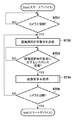
図10は、それぞれ異なる二種類の送信モードが両立したシステムにおけるデジタルカメラ100の処理内容を記載したフローチャートである。
<Processing of
FIG. 10 is a flowchart illustrating the processing contents of the
本実施形態では画像選択許可要求(ロングポーリングリクエスト)を受信すると(ステップS1002)、プッシュ送信を開始し、画像パスリスト取得要求を受信すると(ステップS1009)、プル送信を開始する。また、本実施の形態では、プッシュ送信中に画像パスリスト取得要求を受信すると、プッシュ送信を中断して、プル送信を開始し、プル送信中に画像選択許可要求を受信すると、プル送信を中断して、プッシュ送信を開始しているがこれに限る必要はない。たとえば、プッシュ送信を優先する実施形態においては、プッシュ送信中に画像パスリスト取得要求を受信してもプッシュ送信に遷移しなくてもよい。また、プル送信を優先する実施形態においては、プル送信中に画像選択許可要求を受信しても、プル送信に遷移しなくてもよい。 In the present embodiment, when the image selection permission request (long polling request) is received (step S1002), the push transmission is started, and when the image path list acquisition request is received (step S1009), the pull transmission is started. Further, in the present embodiment, when the image pass list acquisition request is received during the push transmission, the push transmission is interrupted and the pull transmission is started, and when the image selection permission request is received during the pull transmission, the pull transmission is interrupted. Then, push transmission is started, but it is not necessary to limit it to this. For example, in the embodiment in which the push transmission is prioritized, it is not necessary to transition to the push transmission even if the image path list acquisition request is received during the push transmission. Further, in the embodiment in which the pull transmission is prioritized, even if the image selection permission request is received during the pull transmission, it is not necessary to transition to the pull transmission.
以下、プッシュ送信とプル送信が両立したシステムにおけるプル送信モードの動作について、ステップS1002からステップS1008にて説明する。 Hereinafter, the operation of the pull transmission mode in a system in which push transmission and pull transmission are compatible will be described in steps S1002 to S1008.
まず、デジタルカメラ100はスマートデバイス200との間で画像の送受信を行うために、スマートデバイス200との接続処理を行う。ステップS1001にて、制御部101は接続部111を介してスマートデバイス200と接続したことを検知すると、ステップS1002に遷移する。
First, the
次いで、ステップS1002にて、制御部101は接続部111を介して、スマートデバイス200からロングポーリングリクエストを受信する。このロングポーリングリクエストを受信すると、制御部101はスマートデバイス200から画像選択許可を受信したと判断して、ステップS1003に遷移する。ロングポーリングリクエストを受信していなければ、ステップS1009に遷移する。
Next, in step S1002, the
次いで、ステップS1003にて、制御部101は表示部106に図9(a)に示すような送信画像選択画面901を表示する。ステップS1004にて、制御部101は、操作部105を介してユーザからの指示に基づき、送信対称の画像の選択を受け付け、選択された画像を特定する情報を、作業メモリ103に確保した画像リストに追記する。そして、制御部101は、ステップS1005にて、図9(a)の送信ボタン903が操作されたか否かを判定し、送信ボタンが操作されたと判定した場合にはステップS1006に遷移し、否と判定した場合にはステップS1009に処理を進める。
Next, in step S1003, the
次いで、ステップS1006にて、制御部101は接続部111を介して、前述のステップS1002において受信したロングポーリングのリクエストに対する応答として、ユーザの操作に従って構築された画像リストをスマートデバイス200に送信する。この画像リストの情報には、画像ファイルのパスや画像ファイルのサイズなどを含む。これにより、スマートデバイス200は、プッシュ送信の対象となる画像がどの画像なのかを判断することができる。
Next, in step S1006, the
次いで、ステップS1008にて、制御部101は、スマートデバイス200から画像要求の受信と、該当する画像の送信処理を実行する。この間、制御部101は、画像リストに記述された画像の数を把握しているので、送信に係るプログレスバー(図9(c))を表示する。全画像の送信を終えると、制御部101は、ステップS1017に遷移する。
Next, in step S1008, the
次に、プッシュ送信とプル送信が両立したシステムにおけるプル送信モードの動作についてステップS1009からステップS1015にて説明する。 Next, the operation of the pull transmission mode in a system in which push transmission and pull transmission are compatible will be described in steps S1009 to S1015.
まず、ステップS1009にて、制御部101は接続部111を介して、スマートデバイス200から画像パスリスト取得要求を受信したことを検知すると、ファイル送信を開始するために、ステップS1010に遷移する。受信を検知しなかった場合、ステップS1016に遷移する。
First, in step S1009, when the
ステップS1010において、制御部101は表示部106に図9(e)に示すような操作不可画面を示すメッセージを表示する。この表示により、操作部105を操作しても、プッシュ送信開始の指示を行うことができなくする。次いで、ステップS1011にて制御部101は、スマートデバイス200から画像選択許可要求を受信している場合には、この要求に対して、キャンセルしたことを示す応答送信を行う。ここでのキャンセルとしては、HTTPにおけるレスポンスヘッダのステータスコードをエラーコードとして返信するが、これに限る必要はない。たとえば、ステータスコードはエラーコードとせず、レスポンスボディにキャンセルを示す情報を含ませてもよい。スマートデバイス200において、デジタルカメラ100へのロングポーリングリクエストがキャンセルされたことが認識できればよい。また、本実施形態では、画像選択許可要求に対して、キャンセルを行っているが、これに限る必要はない。たとえば、画像選択許可要求を保持したまま、画像パスリストを送信して、プッシュ送信中にプル送信を実現させてもよい。
In step S1010, the
そして、ステップS1009で受信した画像パスリスト取得要求に対して、制御部101は接続部111を介して、記録媒体110に保存されている画像の画像パスのリストをスマートデバイス200に送信する。これにより、スマートデバイス200はデジタルカメラ100の記録媒体に保存されている画像にアクセスするための情報を認識することができる。
Then, in response to the image path list acquisition request received in step S1009, the
一方、ステップS1016において、すでに操作不可画面を表示している場合には、すでにプル送信モードに遷移していると判断して、ステップS1012に遷移する。操作不可画面を表示していない場合には、プル送信モードに遷移していないと判断して、ステップS1002に遷移する。ここで、プル送信モードに遷移していることを操作不可画面を以て判断しているが、これに限る必要はない。例えば、作業用メモリ104に現在の送信モードを示すフラグを記録しておき、そのフラグの情報を参照することで送信モードを判断してもよい。
On the other hand, if the inoperable screen is already displayed in step S1016, it is determined that the pull transmission mode has already been entered, and the process proceeds to step S1012. If the inoperable screen is not displayed, it is determined that the pull transmission mode has not been entered, and the process proceeds to step S1002. Here, the transition to the pull transmission mode is determined by the inoperable screen, but the present invention is not limited to this. For example, a flag indicating the current transmission mode may be recorded in the working
次いで、スマートデバイス200において、図9(f)に示すような画像選択画面を表示するためのサムネイル取得要求に対するデジタルカメラ100の動作を説明する。
Next, in the
まず、ステップS1012において、制御部101は接続部111を介して、スマートデバイス200から画像のサムネイル取得要求を受信すると、ステップS1013に遷移する。ステップS1013では、制御部101は接続部111を介して、スマートデバイス200から指定されたサムネイル画像を送信する。
First, in step S1012, when the
一方、ステップS1012において、制御部101が、画像のサムネイル取得要求を受信しなかったと判断した場合には、ステップS1014に遷移する。
On the other hand, if it is determined in step S1012 that the
ステップS1014とステップS1015を参照して、スマートデバイス200において画像を取得するための画像取得要求に対するデジタルカメラ100の動作を説明する。
With reference to step S1014 and step S1015, the operation of the
まず、ステップS1014において、制御部101は接続部111を介して、スマートデバイス200から画像取得要求を受信すると、ステップS1015に遷移する。ステップS1015では、制御部101は、接続部111を介して、スマートデバイス200から指定された画像を送信する。
First, in step S1014, when the
一方、ステップS1014にて、画像の取得要求を受信していないと判断した場合には、ステップS1017に遷移する。 On the other hand, if it is determined in step S1014 that the image acquisition request has not been received, the process proceeds to step S1017.
最後にステップS1017にて、制御部101はスマートデバイス200との接続を切断したことを検知した場合、処理を終了し、検知しなかった場合、ステップS1002に遷移する。ここで、ステップS1017にて切断検知を行っているが、これに限らなくてもよい。処理中のどのタイミングにおいても切断を検知した際に、処理を終了してもよい。
Finally, in step S1017, when the
<スマートデバイス200の処理>
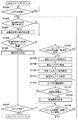
図11は、それぞれ異なる二種類の送信モードが両立したシステムにおけるスマートデバイス200の処理内容を記載したフローチャートである。
<Processing of
FIG. 11 is a flowchart illustrating the processing contents of the
前述のデジタルカメラ100と同様、スマートデバイス200はデジタルカメラ100との間で画像の送受信を行うために、デジタルカメラ100との接続処理を行う。ステップS1101にて、制御部201は接続部211を介してデジタルカメラ100と接続したことを検知すると、ステップS1102に遷移する。
Similar to the
ステップS1102にて、制御部201は画像選択許可要求(ロングポーリングリクエスト)をすでに送信しているか否かを判断する。すでに画像選択許可要求を送信している場合には、プッシュ送信モードに遷移しているため、画像選択許可要求を送信する必要がない。この処理は、その制御を行うための処理である。次いで、ステップS1103にて、制御部201は接続部211を介して、デジタルカメラ100からプッシュ送信対象の画像の情報を取得するためのロングポーリングリクエストを行う。
In step S1102, the
ステップS1104にて、制御部201は接続部211を介して、デジタルカメラ100からロングポーリングリクエストのレスポンスを受信すると、制御部201はステップS1105に処理を遷移する。
In step S1104, when the
ステップS1105にて、制御部101は、受信したレスポンス内容(画像リスト)から画像のパスを取得する。そして。制御部101は、そのパスを利用して、接続部211を介してデジタルカメラ100への画像の送信要求と、画像の受信処理(及び記録媒体210等への格納処理)を繰り返す。この処理は、受信した画像リストに記述された画像の数分行われる。そして、この間、制御部201は、画像の受信の進捗状況がわかるように表示部206に図9(d)に示すようなプログレスバーを表示する。画像リストに記述された全画像の受信を終えると、制御部201は受信した画像を表示部206に表示してもよい。このようにして、デジタルカメラ100で送信する画像を選択し、スマートデバイス200への画像送信を行うプッシュ送信が実現できる。
In step S1105, the
ステップS1104にて、制御部201が、デジタルカメラ100からロングポーリングリクエストのレスポンスを受信しなかったと判断した場合、ステップS1107に遷移する。ステップS1107において、制御部201は、操作部205を介して、図9(b)に示すような操作メニュー内の「カメラ内の画像一覧」のボタン904を押下したか否かを判定する。ボタン904が押下されたと判定した場合、制御部201は、プル送信の処理に遷移するため、処理をステップS1108に遷移する。
If the
以下、ステップS1108からステップS1111にて、制御部201は表示部206に図9(f)に示すような画像のサムネイル一覧画面を表示するために、デジタルカメラ100に保存されている画像リストの取得および画像サムネイルの取得を行う。
Hereinafter, in steps S1108 to S1111, the
次いで、ステップS1112にて、制御部201は、ユーザによる操作部205の操作を検出し、プル転送対称の画像をリストに追加していく。このとき、制御部201は、ユーザが選択した画像を認識しやすいように、図9(f)の参照符号908に示すように、選択した画像にチェックマークを重畳表示する。
Next, in step S1112, the
ステップS1113にて、制御部201は、操作部205を介してのユーザによる、図9(f)の受信ボタン909の押下を検出すると、処理をステップS1114に遷移する。このステップS1114にて、制御部201は、ユーザが選択したリストに示された画像の送信要求を、接続部211を介してデジタルカメラ100に送信しては、その応答である画像の受信処理を、ユーザが選択した画像数分繰り返す。この画像受信を行う際、制御部201は、表示部206に、図9(d)に示すような画像受信の進捗状況が分かるプログレスバーを表示する。
In step S1113, when the
次いで、ステップS1116にて、制御部201は、ユーザによる操作部205に対する操作が、図9(f)のプル転送を終了するためのボタン910であったと判定すると、プル送信を終了し、ステップS1102に遷移する。
Next, in step S1116, when the
なお、全画像の取得を終えた場合には、ステップS1116からステップS1117に遷移しても構わない。そして、制御部201はデジタルカメラ100との接続を切断したことを検知した場合、処理を終了し、検知しなかった場合、ステップS1102に遷移する。ここで、ステップS1117にて切断検知を行っているが、これに限らなくともよい、処理中のどのタイミングにおいても、切断を検知した際に、処理を終了してもよい。
When the acquisition of all the images is completed, the transition from step S1116 to step S1117 may be performed. Then, when the
以上説明したように本第2の実施形態によれば、クライアントサーバ型のシステムを実現するプロトコルにおいて、サーバ機器またはクライアント機器で選択した画像をクライアント機器に送信することを実現できる通信装置を提供することができる。 As described above, according to the second embodiment, in the protocol for realizing a client-server type system, a communication device capable of transmitting an image selected by a server device or a client device to a client device is provided. be able to.
以上、本発明をその好適な実施形態に基づいて詳述してきたが、本発明はこれら特定の実施形態に限られるものではなく、この発明の要旨を逸脱しない範囲の様々な形態も本発明に含まれる。また、上述の実施形態においては、送信対象を画像として説明したが、これに限る必要はない。たとえば、音声ファイルや文書ファイルなど、クライアント機器とサーバ機器の間でやりとりできるファイルであれば何でもよい。 Although the present invention has been described in detail based on the preferred embodiments thereof, the present invention is not limited to these specific embodiments, and various embodiments within the scope of the gist of the present invention are also included in the present invention. included. Further, in the above-described embodiment, the transmission target has been described as an image, but the present invention is not limited to this. For example, any file such as an audio file or a document file that can be exchanged between the client device and the server device may be used.
(その他の実施例)
本発明は、上述の実施形態の1以上の機能を実現するプログラムを、ネットワーク又は記憶媒体を介してシステム又は装置に供給し、そのシステム又は装置のコンピュータにおける1つ以上のプロセッサーがプログラムを読出し実行する処理でも実現可能である。また、1以上の機能を実現する回路(例えば、ASIC)によっても実現可能である。
(Other Examples)
The present invention supplies a program that realizes one or more functions of the above-described embodiment to a system or device via a network or storage medium, and one or more processors in the computer of the system or device reads and executes the program. It is also possible to realize the processing. It can also be realized by a circuit (for example, ASIC) that realizes one or more functions.
100…デジタルカメラ、101、201…制御部、102、202…撮像部、103、203…不揮発性メモリ、104、204…作業用メモリ、105、205…操作部、106、206…表示部、110、210…記録媒体、111、211…通信部、112、212…近距離通信部、200…スマートデバイス 100 ... Digital camera, 101, 201 ... Control unit, 102, 202 ... Imaging unit, 103, 203 ... Non-volatile memory, 104, 204 ... Working memory, 105, 205 ... Operation unit, 106, 206 ... Display unit, 110 , 210 ... Recording medium, 111, 211 ... Communication unit, 112, 212 ... Short-range communication unit, 200 ... Smart device
Claims (11)
画像を記憶する記憶手段と、
リクエスト/レスポンス型の通信プロトコルを用いて通信を行う通信手段と、
前記通信手段を介して受信したクライアントからの要求の種類に応じた処理を行い、前記通信手段を介して応答を返す処理手段と、を有し、
前記処理手段は、
所定の要求を受信した場合、前記所定の要求に対する応答を送信する前に、前記記憶手段に記憶されている画像の一覧を、ユーザが選択可能なユーザインターフェースとして表示する表示手段と、
前記ユーザインターフェースを介してユーザが画像を選択した場合、前記クライアントが前記選択した画像の送信要求を行えるようにするため、前記選択した画像を特定する情報を生成する生成手段と、
前記生成手段が生成した情報を前記所定の要求に対する応答として前記クライアントに送信する送信手段と
を有することを特徴とする画像供給装置。 An image supply device that transmits images in response to requests from clients.
A storage means for storing images and
A communication means that communicates using a request / response type communication protocol,
It has a processing means that performs processing according to the type of request from a client received via the communication means and returns a response via the communication means.
The processing means
When a predetermined request is received, a display means for displaying a list of images stored in the storage means as a user interface that can be selected by the user before transmitting a response to the predetermined request, and a display means.
When a user selects an image via the user interface, a generation means for generating information that identifies the selected image and a generation means for generating information that identifies the selected image so that the client can make a transmission request for the selected image.
An image supply device including a transmission means for transmitting information generated by the generation means to the client as a response to the predetermined request.
前記記憶手段は、前記撮像手段で撮像した画像を記憶する
ことを特徴とする請求項1に記載の画像供給装置。 It also has an imaging means,
The image supply device according to claim 1, wherein the storage means stores an image captured by the imaging means.
前記クライアントから画像のリストの要求を受信した場合、前記クライアントにて送信対象の画像を選択可能とするために、前記記憶手段に記憶されている各画像を特定する情報を前記画像のリストの要求の応答として送信する第2の送信手段を含む
ことを特徴とする請求項1に記載の画像供給装置。 The processing means
When a request for a list of images is received from the client, the request for the list of images is provided with information for identifying each image stored in the storage means so that the client can select an image to be transmitted. The image supply device according to claim 1, further comprising a second transmission means for transmitting as a response to the image.
ことを特徴とする請求項1に記載の画像供給装置。 The image supply device according to claim 1, wherein the information for identifying each image stored in the storage means includes at least one of an image file name, an image ID, and an image path.
前記送信手段は、前記生成手段が生成した情報をプッシュ送信する
ことを特徴とする請求項1に記載の画像供給装置。 The predetermined request is a long polling request.
The image supply device according to claim 1, wherein the transmission means push-transmits information generated by the generation means.
前記所定の要求を受信して表示された前記ユーザインターフェースによる画像選択中に、前記クライアントから前記画像のリストの要求を受信した場合、前記所定の要求についてキャンセルしたこと示す情報を前記所定の要求に対応する応答として送信して、前記第2の送信手段による送信を実行し、且つ、前記ユーザインターフェースを操作不可状態に遷移させる
ことを特徴とする請求項3に記載の画像供給装置。 The processing means
When a request for a list of the images is received from the client during image selection by the user interface displayed after receiving the predetermined request, information indicating that the predetermined request has been canceled is sent to the predetermined request. The image supply device according to claim 3, further comprising transmitting as a corresponding response, executing transmission by the second transmission means, and transitioning the user interface to an inoperable state.
リクエスト/レスポンス型の通信プロトコルを用いて通信を行う通信手段と、
前記通信手段による前記画像供給装置との通信が開始されたことに応じて、前記画像供給装置にて送信対象の画像の選択を行うための所定の要求を、前記通信手段を介して送信すると共に、ユーザによる選択可能な項目を含むメニューを表示する処理手段と、
前記処理手段により表示された前記メニューに項目に対するユーザからの選択がないまま前記所定の要求に対する応答を前記画像供給装置から受信した場合、当該応答に含まれる画像を特定する情報を用いて前記通信手段を介して前記画像供給装置に画像の要求と当該画像の受信処理を行うことで、前記画像供給装置にてユーザが選択した画像を取得する第1の取得手段と、
前記所定の要求に対しての前記画像供給装置からの応答がないまま、前記処理手段で表示されたメニューの中の所定の項目が選択された場合、前記画像供給装置が有する画像の一覧を表す情報の要求及び受信を行い、当該情報に基づき各画像のサムネイルを要求及び受信を行い、各サムネイルに対しユーザが選択可能とするためのユーザインターフェースを表示し、選択されたサムネイルに対応する画像の送信要求及び受信を行うことで、ユーザが選択した画像を取得する第2の取得手段と、
を有することを特徴とする情報処理装置。 An information processing device that communicates with an image supply device that functions as a server and acquires an image from the image supply device.
A communication means that communicates using a request / response type communication protocol,
In response to the start of communication with the image supply device by the communication means, a predetermined request for selecting an image to be transmitted by the image supply device is transmitted via the communication means. , A processing means that displays a menu containing items that can be selected by the user,
When a response to the predetermined request is received from the image supply device without the user selecting an item in the menu displayed by the processing means, the communication is performed using the information for identifying the image included in the response. A first acquisition means for acquiring an image selected by a user in the image supply device by requesting the image supply device for an image and receiving the image via the means.
When a predetermined item in the menu displayed by the processing means is selected without a response from the image supply device to the predetermined request, a list of images possessed by the image supply device is displayed. Requests and receives information, requests and receives thumbnails of each image based on the information, displays a user interface for each thumbnail so that the user can select it, and displays the image corresponding to the selected thumbnail. A second acquisition means for acquiring an image selected by the user by making a transmission request and receiving, and
An information processing device characterized by having.
前記通信手段を介して受信したクライアントからの要求の種類に応じた処理を行い、前記通信手段を介して応答を返す処理工程を有し
前記処理工程は、
所定の要求を受信した場合、前記所定の要求に対する応答を送信する前に、前記記憶手段に記憶されている画像の一覧を、ユーザが選択可能なユーザインターフェースとして表示する表示工程と、
前記ユーザインターフェースを介してユーザが画像を選択した場合、前記クライアントが前記選択した画像の送信要求を行えるようにするため、前記選択した画像を特定する情報を生成する生成工程と、
生成した情報を前記所定の要求に対する応答として前記クライアントに送信する送信工程と
を有することを特徴とする画像供給装置の制御方法。 It is a control method of an image supply device that has a storage means for storing an image and a communication means for communicating using a request / response type communication protocol, and transmits an image in response to a request from a client.
The processing step includes a processing step of performing processing according to the type of request from a client received via the communication means and returning a response via the communication means.
When a predetermined request is received, a display step of displaying a list of images stored in the storage means as a user interface that can be selected by the user before transmitting a response to the predetermined request.
When a user selects an image via the user interface, a generation step of generating information that identifies the selected image and a generation step of generating information that identifies the selected image so that the client can make a transmission request for the selected image.
A control method of an image supply device, which comprises a transmission step of transmitting the generated information to the client as a response to the predetermined request.
前記通信手段による前記画像供給装置との通信が開始されたことに応じて、前記画像供給装置にて送信対象の画像の選択を行うための所定の要求を、前記通信手段を介して送信すると共に、ユーザによる選択可能な項目を含むメニューを表示する処理工程と、
表示された前記メニューに項目に対するユーザからの選択がないまま前記所定の要求に対する応答を前記画像供給装置から受信した場合、当該応答に含まれる画像を特定する情報を用いて前記通信手段を介して前記画像供給装置に画像の要求と当該画像の受信処理を行うことで、前記画像供給装置にてユーザが選択した画像を取得する第1の取得工程と、
前記所定の要求に対しての前記画像供給装置からの応答がないまま、前記処理工程で表示されたメニューの中の所定の項目が選択された場合、前記画像供給装置が有する画像の一覧を表す情報の要求及び受信を行い、当該情報に基づき各画像のサムネイルを要求及び受信を行い、各サムネイルに対しユーザが選択可能とするためのユーザインターフェースを表示し、選択されたサムネイルに対応する画像の送信要求及び受信を行うことで、ユーザが選択した画像を取得する第2の取得工程と
を有することを特徴とする情報処理装置の制御方法。 A control method for an information processing device that has a communication means that communicates using a request / response type communication protocol, communicates with an image supply device that functions as a server, and acquires an image from the image supply device.
In response to the start of communication with the image supply device by the communication means, a predetermined request for selecting an image to be transmitted by the image supply device is transmitted via the communication means. , A processing process that displays a menu containing items that can be selected by the user,
When a response to the predetermined request is received from the image supply device without the user selecting the item in the displayed menu, the information for identifying the image included in the response is used via the communication means. The first acquisition step of acquiring an image selected by the user in the image supply device by requesting the image to the image supply device and receiving the image.
When a predetermined item in the menu displayed in the processing step is selected without a response from the image supply device to the predetermined request, a list of images possessed by the image supply device is displayed. Requests and receives information, requests and receives thumbnails of each image based on the information, displays a user interface for each thumbnail so that the user can select it, and displays the image corresponding to the selected thumbnail. A control method for an information processing apparatus, which comprises a second acquisition step of acquiring an image selected by a user by making a transmission request and receiving.
Priority Applications (2)
| Application Number | Priority Date | Filing Date | Title |
|---|---|---|---|
| JP2017091945A JP6858069B2 (en) | 2017-05-02 | 2017-05-02 | Image supply device and information processing device and their control methods and programs |
| US15/966,051 US10997230B2 (en) | 2017-05-02 | 2018-04-30 | Image supply apparatus, information processing apparatus, control method thereof, and storage medium |
Applications Claiming Priority (1)
| Application Number | Priority Date | Filing Date | Title |
|---|---|---|---|
| JP2017091945A JP6858069B2 (en) | 2017-05-02 | 2017-05-02 | Image supply device and information processing device and their control methods and programs |
Publications (3)
| Publication Number | Publication Date |
|---|---|
| JP2018191134A JP2018191134A (en) | 2018-11-29 |
| JP2018191134A5 JP2018191134A5 (en) | 2020-05-14 |
| JP6858069B2 true JP6858069B2 (en) | 2021-04-14 |
Family
ID=64015330
Family Applications (1)
| Application Number | Title | Priority Date | Filing Date |
|---|---|---|---|
| JP2017091945A Active JP6858069B2 (en) | 2017-05-02 | 2017-05-02 | Image supply device and information processing device and their control methods and programs |
Country Status (2)
| Country | Link |
|---|---|
| US (1) | US10997230B2 (en) |
| JP (1) | JP6858069B2 (en) |
Families Citing this family (4)
| Publication number | Priority date | Publication date | Assignee | Title |
|---|---|---|---|---|
| JP6956515B2 (en) * | 2017-05-02 | 2021-11-02 | キヤノン株式会社 | Communication systems, communication devices and their control methods and programs |
| JP6882055B2 (en) * | 2017-05-02 | 2021-06-02 | キヤノン株式会社 | Communication devices and their control methods, programs and communication systems |
| CN111953896A (en) * | 2020-07-23 | 2020-11-17 | 西安万像电子科技有限公司 | Image display method, device and system |
| US20230353640A1 (en) * | 2022-04-27 | 2023-11-02 | Viam Inc. | Device control system and method |
Family Cites Families (9)
| Publication number | Priority date | Publication date | Assignee | Title |
|---|---|---|---|---|
| JP2003050703A (en) * | 2001-08-03 | 2003-02-21 | Fuji Photo Film Co Ltd | Portable communications equipment, portable electronic equipment and method for control operation of them |
| JP2007020037A (en) * | 2005-07-11 | 2007-01-25 | Nikon Corp | Electronic camera |
| JP2008129729A (en) * | 2006-11-17 | 2008-06-05 | Olympus Corp | Information processor and control program |
| JP2009212743A (en) * | 2008-03-04 | 2009-09-17 | Sony Corp | Electronic apparatus, transmission method, and program |
| JP5554218B2 (en) * | 2009-12-14 | 2014-07-23 | パナソニック株式会社 | Electronic equipment, communication system |
| US20120131465A1 (en) * | 2010-11-18 | 2012-05-24 | Telek Michael J | Digital image display device with remote viewing interface |
| JP5810761B2 (en) * | 2011-09-01 | 2015-11-11 | セイコーエプソン株式会社 | Process control server and process control method |
| JP5882768B2 (en) | 2012-02-03 | 2016-03-09 | キヤノン株式会社 | Image processing apparatus, control method thereof, and program |
| US20140201376A1 (en) * | 2013-01-11 | 2014-07-17 | Andre Godin | Method and system for the handling of redundant long poll |
-
2017
- 2017-05-02 JP JP2017091945A patent/JP6858069B2/en active Active
-
2018
- 2018-04-30 US US15/966,051 patent/US10997230B2/en active Active
Also Published As
| Publication number | Publication date |
|---|---|
| US10997230B2 (en) | 2021-05-04 |
| JP2018191134A (en) | 2018-11-29 |
| US20180322148A1 (en) | 2018-11-08 |
Similar Documents
| Publication | Publication Date | Title |
|---|---|---|
| JP6858069B2 (en) | Image supply device and information processing device and their control methods and programs | |
| JP6755081B2 (en) | Communication equipment and its control method and program | |
| KR20150015246A (en) | image photographing apparatus , user device and method for establishing communications between image photographing apparatus and user device | |
| CN106663068B (en) | Communication apparatus connectable by near field communication, method of controlling the same, and recording medium | |
| JP6433265B2 (en) | Information processing apparatus, electronic device, control method thereof, program, and storage medium | |
| JP7175634B2 (en) | Communication device, control method and program | |
| JP6882055B2 (en) | Communication devices and their control methods, programs and communication systems | |
| JP6385078B2 (en) | COMMUNICATION DEVICE, COMMUNICATION DEVICE CONTROL METHOD, PROGRAM | |
| JP6222979B2 (en) | COMMUNICATION DEVICE, COMMUNICATION DEVICE CONTROL METHOD, PROGRAM | |
| JP6415232B2 (en) | COMMUNICATION DEVICE, COMMUNICATION DEVICE CONTROL METHOD, PROGRAM | |
| JP7218164B2 (en) | Communication device and its control method | |
| CN108989543B (en) | Communication apparatus, control method thereof, and storage medium | |
| JP6570575B2 (en) | Imaging apparatus, control method therefor, and program | |
| JP6869656B2 (en) | Transmitter, receiver, and communication system | |
| JP2020057899A (en) | Wireless communication system and wireless communication terminal control method | |
| JP2016054390A (en) | Communication apparatus, control method for the communication apparatus, and program | |
| JP6433231B2 (en) | COMMUNICATION DEVICE, COMMUNICATION DEVICE CONTROL METHOD, PROGRAM | |
| JP6386862B2 (en) | COMMUNICATION DEVICE, COMMUNICATION DEVICE CONTROL METHOD, PROGRAM | |
| JP2019004422A (en) | Communication device, control method, and program | |
| JP2017085518A (en) | Communication apparatus, control method for communication apparatus, and program | |
| JP7086743B2 (en) | Communication device, control method of communication device, program | |
| JP6956515B2 (en) | Communication systems, communication devices and their control methods and programs | |
| JP2023125841A (en) | Communication apparatus, communication control method, and program | |
| JP2016100724A (en) | Information processing device, information processing method, and program | |
| JP2022178114A (en) | Communication device, control method, and program |
Legal Events
| Date | Code | Title | Description |
|---|---|---|---|
| A521 | Request for written amendment filed |
Free format text: JAPANESE INTERMEDIATE CODE: A523 Effective date: 20200402 |
|
| A621 | Written request for application examination |
Free format text: JAPANESE INTERMEDIATE CODE: A621 Effective date: 20200402 |
|
| A977 | Report on retrieval |
Free format text: JAPANESE INTERMEDIATE CODE: A971007 Effective date: 20201221 |
|
| RD01 | Notification of change of attorney |
Free format text: JAPANESE INTERMEDIATE CODE: A7421 Effective date: 20210103 |
|
| A521 | Request for written amendment filed |
Free format text: JAPANESE INTERMEDIATE CODE: A523 Effective date: 20210113 |
|
| TRDD | Decision of grant or rejection written | ||
| A01 | Written decision to grant a patent or to grant a registration (utility model) |
Free format text: JAPANESE INTERMEDIATE CODE: A01 Effective date: 20210222 |
|
| A61 | First payment of annual fees (during grant procedure) |
Free format text: JAPANESE INTERMEDIATE CODE: A61 Effective date: 20210323 |
|
| R151 | Written notification of patent or utility model registration |
Ref document number: 6858069 Country of ref document: JP Free format text: JAPANESE INTERMEDIATE CODE: R151 |