Silage raw material cutting and conveying throwing equipment for livestock raising
Technical Field
The invention belongs to the technical field of silage and livestock raising equipment, and particularly relates to silage raw material cutting, conveying and throwing equipment for livestock raising.
Background
Ensiling is a storage technique or method for compacting and sealing fresh plant varieties to isolate the stored green feed from outside air, so that oxygen deficiency is caused inside the stored green feed, anaerobic fermentation is caused, organic acid is generated, the fresh plant feed can be stored for a long time, the nutrient loss can be reduced, and the digestion and absorption of animals are facilitated.
Based on the above, the inventor finds that the existing silage raw material cutting, conveying and throwing device has the following defects in practical use: 1. when the silage raw materials are cut, the silage raw materials may contain iron impurities, if the silage raw materials are not removed, the iron impurities contained in the silage raw materials are easy to damage animals when the silage raw materials are fed to the animals; 2. when the silage raw materials are cut and conveyed, soil can be adhered to the root area of the silage raw materials, so that the soil flies everywhere during conveying and throwing, and large pollution is caused; 3. the cutting, conveying and putting of the existing silage raw materials are arranged when the silage raw materials are conveyed and put in, the putting angle cannot be adjusted, and the silage raw materials cannot adapt to different environment places.
Therefore, in view of the above, research and improvement are made for the existing structure and defects, and a silage material cutting, conveying and throwing device for livestock raising is provided, so as to achieve the purpose of higher practical value.
Disclosure of Invention
In order to solve the technical problems, the invention provides silage raw material cutting, conveying and throwing equipment for livestock raising, and aims to solve the problems that iron impurities cannot be removed when the existing silage raw material cutting, conveying, breaking and throwing equipment is actually used, soil flies everywhere and the throwing angle is not adjustable.
The invention relates to a cutting, conveying and throwing device for silage raw materials for livestock, which is realized by the following specific technical means:
the silage raw material cutting, conveying and throwing equipment for livestock comprises a shell, a land wheel, a first fan, a cylinder electromagnet, a first lug plate structure, a first feed delivery cylinder, a first conical structure, a second lug plate structure, a second feed delivery cylinder, a second conical structure, a third lug plate structure, a second fan, a filtering cylinder, a check ring, a cover plate, a first motor rotating shaft, a beating plate, a second motor, a first belt pulley, a discharge cylinder, a first sector plate, a sector sliding cylinder, a second sector plate, a third sector plate, a stud, a nut, a round rod, a fixing bolt, a conveying auger, a second belt pulley, a cutting rotating shaft, a Y-shaped flail knife, a third belt pulley and a first motor rotating shaft; the front of the shell is rotationally connected with the land wheel; the inner part of the front end of the shell, which is connected with the charging barrel, is rotatably connected with the conveying auger, and a rotating shaft at the right end of the conveying auger is fixedly connected with the second belt pulley positioned at the right side of the shell; the first fan communicated with the receiving barrel is arranged on the left end face of the shell corresponding to the receiving barrel, and the first fan is fixedly connected with a first material conveying barrel; the other end of the first material conveying cylinder is of a first conical structure, and two second lug plate structures are welded at the position of the first conical structure in an annular array manner; the inner end of the shell is positioned behind the material receiving barrel and is rotationally connected with the cutting rotating shaft, and a plurality of groups of Y-shaped flail knives are embedded on the cutting rotating shaft; the right end rotating shaft of the cutting rotating shaft is fixedly connected with a third belt pulley which is positioned at the right side of the shell and is positioned at the same horizontal line with the second belt pulley, and the axle center of the third belt pulley is also fixedly connected with a first motor rotating shaft; the central part of the top end of the shell is fixedly provided with the filtering cylinder, and the top end of the filtering cylinder is fixedly connected with the second material conveying cylinder communicated with the inner cavity of the filtering cylinder; the other end of the second conveying cylinder is of a second conical structure, and two third lug plate structures are welded on the part of the second conical structure in an annular array manner; the cylindrical electromagnet is arranged between the second conical structure and the first conical structure, and the outer walls of the head end and the tail end of the cylindrical electromagnet are in annular arrays and are respectively welded with two first lug plate structures; the cylindrical electromagnet is fixedly arranged between the second conical structure and the first conical structure through two fixing bolts which respectively penetrate through the third lug plate structure, the second lug plate structure and the first lug plate structure; the second motor is fixedly installed at the position, adjacent to the rear part of the filtering cylinder, of the top end of the machine shell, and the first belt pulley which is located on the same horizontal line with the rotating shaft of the first motor is fixedly connected with the rotating shaft end of the second motor.
Furthermore, the inner wall of the filtering cylinder is welded with a check ring on the right side of the position communicated with the second material conveying cylinder, and one end of the longitudinal section of the check ring is of a triangular structure.
Furthermore, the left end of the filtering cylinder is fixedly provided with one cover plate through a bolt, the left end surface of the cover plate is fixedly provided with one first motor, and a first motor rotating shaft of the first motor is positioned on the inner wall of the filtering cylinder.
Furthermore, four beating plates are embedded in the position, located on the left side of the retainer ring, of the outer wall of the rotating shaft of the first motor in an annular array manner, and the positions of the four beating plates correspond to the positions of the communication positions of the second material conveying cylinder and the filtering cylinder.
Furthermore, the right end of the filtering cylinder is fixedly provided with one second fan, the top end of the second fan is fixedly connected with one discharging cylinder, the top end of the discharging cylinder is of an arc-shaped structure of a quarter circle, and the inner end of the arc-shaped structure of the top end of the discharging cylinder is welded with one first fan-shaped plate.
Furthermore, one is slidably sleeved on the top end of the discharge barrel, a notch is formed in the position, corresponding to the first sector plate, of the sector sliding barrel, the left side and the right side of the notch formed in the sector sliding barrel are respectively welded with the second sector plate and the third sector plate, and the third sector plate is welded with a stud penetrating through the first sector plate and the second sector plate.
Furthermore, the top ends of the fan-shaped sliding cylinder and the discharging cylinder are consistent and are of quarter-circle arc structures.
Furthermore, the stud is connected with one nut in a threaded fit mode, and the outer wall of the nut is in an annular array shape and is welded with two round rods.
Compared with the prior art, the invention has the following beneficial effects:
a cylindrical electromagnet is arranged between a second conical structure and a first conical structure, two first lug plate structures are welded on the outer walls of the head end and the tail end of the cylindrical electromagnet in an annular array mode respectively, the cylindrical electromagnet is fixedly installed between the second conical structure and the first conical structure through two fixing bolts which penetrate through a third lug plate structure, a second lug plate structure and the first lug plate structures respectively, and when cut and crushed silage raw materials are conveyed in a first feed conveying cylinder and a second feed conveying cylinder, iron impurities possibly existing in the silage raw materials are adsorbed and filtered through the cylindrical electromagnet with strong magnetism after power is turned on, so that the iron impurities are prevented from being mixed in the silage raw materials and causing injury to animals during subsequent feeding of the animals.
Four beating plates are embedded in the position, located on the left side of the retainer ring, of the outer wall of the first motor rotating shaft in an annular array mode, the four beating plates correspond to the position of the communication position of the second material conveying cylinder and the filtering cylinder, when cut and crushed silage raw materials are conveyed into the filtering cylinder through the first material conveying cylinder and the second material conveying cylinder, the beating plates embedded in the first motor rotating shaft are rotated at a high speed to beat the silage raw materials entering the filtering cylinder, soil and the like possibly adhered to the silage raw materials are beaten down, a retainer ring is welded on the right side of the inner wall of the filtering cylinder relative to the communication position of the second material conveying cylinder, one end of the longitudinal section of the retainer ring is of a triangular structure, and the beaten soil can be gathered in the filtering cylinder through the arrangement of the retainer ring on the inner wall of the filtering cylinder.
According to the invention, the top end of the discharge barrel is sleeved with the fan-shaped sliding barrel in a sliding manner, the fan-shaped sliding barrel and the top end of the discharge barrel are consistent and are of a quarter-circle arc structure, and workers can adjust the position of the fan-shaped sliding barrel by sliding along the top end of the discharge barrel and fix the fan-shaped sliding barrel by screwing the nut, so that the angle of discharging cut and crushed silage raw materials through the discharge barrel is adjusted, and the discharge environment is adapted to the current conveying environment.
Drawings
Fig. 1 is a schematic axial view of the present invention.
Fig. 2 is a schematic view of the present invention at a part enlarged in fig. 1.
Fig. 3 is a schematic structural view of the cylinder electromagnet in fig. 2 in a disassembled state.
Fig. 4 is a partial sectional view of the front end of the casing connected with the cartridge according to the present invention.
Fig. 5 is a schematic view of the present invention at a part B enlarged in fig. 4.
Fig. 6 is a schematic view of the sliding adjustment state of the sector-shaped sliding barrel in fig. 5 of the invention.
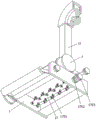
Fig. 7 is a schematic view of the present invention in an axial view, side view, bottom view.
Fig. 8 is a schematic view of the internal cross-sectional structure of the filtering cylinder of the present invention.
In the drawings, the corresponding relationship between the component names and the reference numbers is as follows:
1-a machine shell, 2-a land wheel, 3-a first fan, 4-a cylindrical electromagnet, 401-a first lug plate structure, 5-a first feed delivery cylinder, 501-a first conical structure, 502-a second lug plate structure, 6-a second feed delivery cylinder, 601-a second conical structure, 602-a third lug plate structure, 7-a second fan, 8-a filtering cylinder, 801-a retainer ring, 9-a cover plate, 10-a first motor, 1001-a first motor rotating shaft, 1002-a beating plate, 11-a second motor, 1101-a first belt pulley, 12-a discharge cylinder, 1201-a first sector plate, 13-a sector sliding cylinder, 1301-a second sector plate, 1302-a third sector plate, 1303-a stud, 1303-a nut, 14-a nut, 1401-a round rod and 15-a fixed bolt, 16-conveying auger, 1601-second belt pulley, 17-cutting rotating shaft, 1701-Y-shaped flail knife, 1702-third belt pulley and 1703-first motor rotating shaft.
Detailed Description
The embodiments of the present invention will be described in further detail with reference to the drawings and examples. The following examples are intended to illustrate the invention but are not intended to limit the scope of the invention.
In the description of the present invention, "a plurality" means two or more unless otherwise specified; the terms "upper", "lower", "left", "right", "inner", "outer", "front", "rear", "head", "tail", and the like, indicate orientations or positional relationships based on the orientations or positional relationships shown in the drawings, are only for convenience in describing and simplifying the description, and do not indicate or imply that the device or element referred to must have a particular orientation, be constructed in a particular orientation, and be operated, and thus, should not be construed as limiting the invention. Furthermore, the terms "first," "second," "third," and the like are used for descriptive purposes only and are not to be construed as indicating or implying relative importance.
In the description of the present invention, it is to be noted that, unless otherwise explicitly specified or limited, the terms "connected" and "connected" are to be interpreted broadly, e.g., as being fixed or detachable or integrally connected; can be mechanically or electrically connected; may be directly connected or indirectly connected through an intermediate. The specific meanings of the above terms in the present invention can be understood in specific cases to those skilled in the art.
Example (b):
as shown in figures 1 to 8:
the invention provides silage raw material cutting, conveying and throwing equipment for livestock raising, which comprises a machine shell 1, a land wheel 2, a first fan 3, a cylindrical electromagnet 4, a first lug plate structure 401, a first feed cylinder 5, a first conical structure 501, a second lug plate structure 502, a second feed cylinder 6, a second conical structure 601, a third lug plate structure 602, a second fan 7, a filtering cylinder 8, a check ring 801, a cover plate 9, a first motor 10, a first motor rotating shaft, a beating plate 1002, a second motor 11, a first belt pulley 1101, a discharge cylinder 12, a first sector plate 1201, a sector sliding cylinder 13, a second sector plate 1301, a third sector plate 1302, a stud 1303, a nut 14, a round rod 1401, a fixing bolt 15, a conveying auger 16, a second belt pulley 1701601, a cutting rotating shaft 17, a Y-shaped swinging knife 1701, a third belt pulley 1702 and a first motor rotating shaft 3; the front of the shell 1 is rotationally connected with one land wheel 2; the inner part of the front end of the casing 1 connected with the charging barrel is rotatably connected with the conveying auger 16, and a rotating shaft at the right end of the conveying auger 16 is fixedly connected with the second belt pulley 1601 positioned at the right side of the casing 1; the first fan 3 communicated with the left end face of the shell 1 corresponding to the material receiving barrel is arranged on the left end face of the shell 1, and the first material conveying barrel 5 is fixedly connected to the first fan 3; the other end of the first material conveying cylinder 5 is provided with a first conical structure 501, and the positions of the first conical structures 501 are in an annular array shape and are welded with two second lug plate structures 502; the inner end of the machine shell 1 is rotatably connected with one cutting rotating shaft 17 at the rear side of the material receiving barrel part, and a plurality of groups of Y-shaped flail knives 1701 are embedded on the cutting rotating shaft 17; the right end rotating shaft of the cutting rotating shaft 17 is fixedly connected with a third belt pulley 1702 which is positioned at the right side of the machine shell 1 and is positioned at the same horizontal line with the second belt pulley 1601, and the axle center of the third belt pulley 1702 is also fixedly connected with a first motor rotating shaft 1703; the central part of the top end of the machine shell 1 is fixedly provided with the filtering cylinder 8, and the top end of the filtering cylinder 8 is fixedly connected with the second material conveying cylinder 6 communicated with the inner cavity of the filtering cylinder; the other end of the second feed delivery cylinder 6 is provided with a second conical structure 601, and two third lug plate structures 602 are welded on the second conical structure 601 in an annular array manner; the cylindrical electromagnet 4 is arranged between the second conical structure 601 and the first conical structure 501, and the two first lug plate structures 401 are welded on the outer walls of the head end and the tail end of the cylindrical electromagnet 4 in an annular array shape respectively; the cylindrical electromagnet 4 is fixedly installed between the second conical structure 601 and the first conical structure 501 through two fixing pins 15 respectively inserted through the third lug plate structure 602, the second lug plate structure 502 and the first lug plate structure 401; the second motor 11 is fixedly installed at a position, adjacent to the rear part of the filtering cylinder 8, at the top end of the casing 1, and the first belt pulley 1101 which is positioned at the same horizontal line with the first motor rotating shaft 1703 is fixedly connected with a rotating shaft end of the second motor 11.
The inner wall of the filtering cylinder 8 is welded with the retainer ring 801 on the right side of the communicating position of the second material conveying cylinder 6, and one end of the longitudinal section of the retainer ring 801 is of a triangular structure, so that the beaten soil is gathered in the filtering cylinder 8.
The left end of the filtering cylinder 8 is fixedly provided with one cover plate 9 through a bolt, the left end face of the cover plate 9 is fixedly provided with one first motor 10, and a first motor rotating shaft 1001 of the first motor 10 is positioned on the inner wall of the filtering cylinder 8.
Four beating plates 1002 are embedded in the outer wall of the first motor rotating shaft 1001 at the left side of the retainer ring 801 in an annular array manner, the positions of the four beating plates 1002 and the communication position of the second material conveying cylinder 6 and the filtering cylinder 8 correspond to each other, the beating plates 1002 embedded in the first motor rotating shaft 1001 are rotated at a high speed to beat silage raw materials entering the filtering cylinder 8, and soil and the like possibly adhered to the silage raw materials are beaten down.
The right end of the filtering cylinder 8 is fixedly provided with one second fan 7, the top end of the second fan 7 is fixedly connected with one discharge cylinder 12, the top end of the discharge cylinder 12 is of a quarter-circle arc structure, and the inner end of the arc structure at the top end of the discharge cylinder 12 is welded with one first fan-shaped plate 1201.
The top end of the discharge barrel 12 is slidably sleeved with one fan-shaped sliding barrel 13, a notch is formed in the position, corresponding to the first fan-shaped plate 1201, of the fan-shaped sliding barrel 13, the second fan-shaped plate 1301 and the third fan-shaped plate 1302 are welded to the left side and the right side of the notch formed in the fan-shaped sliding barrel 13 respectively, and the stud 1303 penetrating through the first fan-shaped plate 1201 and the second fan-shaped plate 1301 is welded to the third fan-shaped plate 1302.
The fan-shaped sliding barrel 13 and the top end of the discharging barrel 12 are consistent and are of a quarter-circle arc-shaped structure, and a worker can adjust the angle of discharging cut and crushed silage materials through the discharging barrel 12 by sliding and adjusting the fan-shaped sliding barrel 13 along the top end of the discharging barrel 12 so as to adapt to the current environment.
The nut 14 is connected to the stud 1303 in a threaded fit manner, and two round rods 1401 are welded to the outer wall of the nut 14 in an annular array manner, so that the nut 14 can be conveniently twisted.
The specific use mode and function of the embodiment are as follows:
the invention is installed at the rear of a tractor, a cylindrical electromagnet 4, a first motor 10 and a second motor 11 are all powered by the tractor, a first belt pulley 1101 fixedly connected with the rotating shaft end of the second motor 11 is connected with a first motor rotating shaft 1703 of a cutting rotating shaft 17 through a belt, and a third belt pulley 1702 of the cutting rotating shaft 17 is also connected with a second belt pulley 1601 of a conveying auger 16 through the belt; when the first motor 10 works, the first motor shaft 1001 drives the cutting rotating shaft 17 to rotate at a high speed, the silage raw materials are cut and crushed by the Y-shaped flail knife 1701 embedded on the cutting rotating shaft 17, the silage raw materials are flaked into the material receiving cylinder by the Y-shaped flail knife 1701 along with air flow, the silage raw materials are conveyed to the position of the first fan 3 by the conveying auger 16, the first fan 3 conveys the cut and crushed silage raw materials into the filtering cylinder 8 through the first material conveying cylinder 5 and the second material conveying cylinder 6, and when the cut and crushed silage raw materials are conveyed in the first material conveying cylinder 5 and the second material conveying cylinder 6, iron impurities possibly existing in the silage raw materials are adsorbed and filtered by the cylinder electromagnet 4 which is strong in power supply so as to prevent the iron impurities from being mixed in the silage raw materials and causing damage to animals when the animals are subsequently fed; when the cut and crushed silage raw materials are conveyed into the filtering cylinder 8 through the first feed cylinder 5 and the second feed cylinder 6, the beating plate 1002 embedded on the first motor rotating shaft 1001 is rotated at a high speed to beat the silage raw materials entering the filtering cylinder 8, soil and the like possibly adhered to the silage raw materials are beaten, the beaten soil can be gathered in the filtering cylinder 8 through the arrangement of the retaining ring 801 on the inner wall of the filtering cylinder 8, the light silage raw materials are conveyed into the discharge cylinder 12 through the second fan 7, and the cut and crushed silage raw materials are output through the discharge cylinder 12; the working personnel can adjust the fan-shaped sliding barrel 13 by sliding along the top end of the discharging barrel 12 and fix the fan-shaped sliding barrel 13 by screwing the nut 14, so that the discharging angle of the cut and crushed silage raw material through the discharging barrel 12 is adjusted to adapt to the current environment; after the silage raw materials are conveyed, a worker can detach and take down the fixing bolt 15 for fixing the cylindrical electromagnet 4, so that iron impurities in the cylindrical electromagnet 4 can be cleaned conveniently; the bolts securing the cover plate 9 can then be removed to remove the cover plate 9 for cleaning the dirt in the filter cylinder 8.
The embodiments of the present invention have been presented for purposes of illustration and description, and are not intended to be exhaustive or limited to the invention in the form disclosed. Many modifications and variations will be apparent to those of ordinary skill in the art. The embodiment was chosen and described in order to best explain the principles of the invention and the practical application, and to enable others of ordinary skill in the art to understand the invention for various embodiments with various modifications as are suited to the particular use contemplated.