CN1088486C - Unsymmetrical steel sheet pile and method for manufacturing the same - Google Patents
Unsymmetrical steel sheet pile and method for manufacturing the same Download PDFInfo
- Publication number
- CN1088486C CN1088486C CN96191138A CN96191138A CN1088486C CN 1088486 C CN1088486 C CN 1088486C CN 96191138 A CN96191138 A CN 96191138A CN 96191138 A CN96191138 A CN 96191138A CN 1088486 C CN1088486 C CN 1088486C
- Authority
- CN
- China
- Prior art keywords
- sheet pile
- steel sheet
- joint
- asymmetric
- mentioned
- Prior art date
- Legal status (The legal status is an assumption and is not a legal conclusion. Google has not performed a legal analysis and makes no representation as to the accuracy of the status listed.)
- Expired - Lifetime
Links
Images


Classifications
-
- B—PERFORMING OPERATIONS; TRANSPORTING
- B21—MECHANICAL METAL-WORKING WITHOUT ESSENTIALLY REMOVING MATERIAL; PUNCHING METAL
- B21B—ROLLING OF METAL
- B21B1/00—Metal-rolling methods or mills for making semi-finished products of solid or profiled cross-section; Sequence of operations in milling trains; Layout of rolling-mill plant, e.g. grouping of stands; Succession of passes or of sectional pass alternations
- B21B1/08—Metal-rolling methods or mills for making semi-finished products of solid or profiled cross-section; Sequence of operations in milling trains; Layout of rolling-mill plant, e.g. grouping of stands; Succession of passes or of sectional pass alternations for rolling structural sections, i.e. work of special cross-section, e.g. angle steel
- B21B1/082—Piling sections having lateral edges specially adapted for interlocking with each other in order to build a wall
-
- E—FIXED CONSTRUCTIONS
- E02—HYDRAULIC ENGINEERING; FOUNDATIONS; SOIL SHIFTING
- E02D—FOUNDATIONS; EXCAVATIONS; EMBANKMENTS; UNDERGROUND OR UNDERWATER STRUCTURES
- E02D5/00—Bulkheads, piles, or other structural elements specially adapted to foundation engineering
- E02D5/02—Sheet piles or sheet pile bulkheads
- E02D5/03—Prefabricated parts, e.g. composite sheet piles
- E02D5/04—Prefabricated parts, e.g. composite sheet piles made of steel
-
- B—PERFORMING OPERATIONS; TRANSPORTING
- B21—MECHANICAL METAL-WORKING WITHOUT ESSENTIALLY REMOVING MATERIAL; PUNCHING METAL
- B21B—ROLLING OF METAL
- B21B1/00—Metal-rolling methods or mills for making semi-finished products of solid or profiled cross-section; Sequence of operations in milling trains; Layout of rolling-mill plant, e.g. grouping of stands; Succession of passes or of sectional pass alternations
- B21B1/08—Metal-rolling methods or mills for making semi-finished products of solid or profiled cross-section; Sequence of operations in milling trains; Layout of rolling-mill plant, e.g. grouping of stands; Succession of passes or of sectional pass alternations for rolling structural sections, i.e. work of special cross-section, e.g. angle steel
-
- E—FIXED CONSTRUCTIONS
- E02—HYDRAULIC ENGINEERING; FOUNDATIONS; SOIL SHIFTING
- E02D—FOUNDATIONS; EXCAVATIONS; EMBANKMENTS; UNDERGROUND OR UNDERWATER STRUCTURES
- E02D2600/00—Miscellaneous
- E02D2600/20—Miscellaneous comprising details of connection between elements
Abstract
The present invention relates to an unsymmetrical steel sheet pile and a method for manufacturing the same and a corner steel sheet pile and a method for manufacturing the same, both being used for the unsymmetrical steel sheet pile and the method for manufacturing the same, in which good joint shapes can be obtained without forming any convex portion by making a joint portion of a sheet pile wall become flush with a flat arm portion, also a satisfactory joint shape can be obtained without generating an unstable rolling attitude and an incomplete joint forming by finishing joint bending forming. One of unsymmetrical joints has a turned-up shape, while the other has a turned-down shape, and in forming left and right joint bends rolls with different passes are used on respective sides for finishing the bends. During this process, while the formation of one of the joint bends is being finished, the other joint is only restrained in the pass with bend formation not carried out at all or carried out halfway. The corner steel sheet pile is manufactured by inverting either the inward joint portion of the above unsymmetrical steel sheet pile or the outward joint portion thereof. In another method, it is possible to manufacture it by inwardly bending either of the joints.
Description
The present invention relates to for example be used for steel sheet pile and the manufacture method thereof that civil construction is used, particularly relate to steel sheet pile (hereinafter referred to as asymmetric steel sheet pile) with the asymmetric joint geometry in the left and right sides and the manufacture method that adopts hot rolling thereof.
The invention still further relates to the bight steel sheet pile and the manufacture method thereof in the bight that is used for the steel plate pile lining.
Though steel sheet pile has multiple, wherein general is that section is trapezoidal U-shaped steel sheet pile.Also be to describe below with the example of U-shaped steel sheet pile as steel sheet pile.
Recently, when forming the wall body that uses existing U-shaped steel sheet pile, produce such problem, promptly, because each block plate stake all must oppositely set up and down, so the construction period of wall body is long, in addition, because the thickness (width) of wall body is bigger than the construction method that adopts small-sized i iron, so the construction of inappropriate city suburbs portion, the construction of the suburbs, city portion from effective viewpoint of utilizing soil require with in abutting connection with nestle up construction.
In order to address this problem, the applicant opens the Japanese patent gazette spy and discloses a kind of U-shaped steel sheet pile with brand-new asymmetric joint for flat 5-140928 number.Fig. 1 is disclosed simplification profile with steel sheet pile 1 of the asymmetric joint geometry in the left and right sides in the above-mentioned communique, and hence one can see that, and steel sheet pile 1 is made of flange part 2, web portion 3 and asymmetric the connector portions 4,5 that is located at both sides.
Fig. 2 a for will above-mentioned asymmetric steel sheet pile 1 nestle up practically in abutting connection with (A.L.) be used in the mode declaration pattern specification figure of combination example of the occasion of retaining wall etc.Compare with Fig. 2 b that the occasion that adopts existing symmetrical steel sheet pile 6 is shown, can know and to effectively utilize the space.Among the figure, the zone is mechanical occupied area (W.A.) shown in the dotted line, and it illustrates such zone,, just can at the scene steel sheet pile be squeezed in the soil in this zone as the zone as long as promptly can guarantee this point.Can also know in addition, with regard to the thickness (D of planned sheet pile wall
1, D
2), the occasion of Fig. 2 (a) obviously narrows down.
Like this, according to above-mentioned asymmetric U-shaped steel sheet pile, then when shown in Fig. 2 (a), forming planned sheet pile wall like that, can on same direction, set steel sheet pile continuously, and the wall body that forms like this has the section rigidity that is equal to or surpasses the occasion that adopts existing symmetrical U-shaped steel sheet pile.Yet, set like that continuously as shown in the figure when forming wall, unavoidably form protuberance 5a in connector portions.
Yet, as well-known,, form continuous retaining wall though two end joints of U-shaped steel sheet pile can be mutually combined, squeeze in the ground, but, to use bight steel sheet pile with section different with other parts in corner portion in the occasion of the direction that changes this wall.Be referred to as the bight steel sheet pile below.
Special public clear 64-8139 number of Japanese patent gazette, special fair 2-60807 number, special fair 6-9682 number etc. several existing this bights steel sheet pile is disclosed, in addition, Japanese patent gazette is special public number discloses its manufacture method according to 64-10281 number, special fair 6-9682.
Squeezing into the occasion with U-shaped steel sheet pile of new asymmetric joint as described above continuously, the same with existing symmetrical steel plate pile lining, also have to use the bight steel sheet pile of special shape in the bight.
Fig. 3 (a) and Fig. 4 (a) are depicted as existing bight steel sheet pile.Shown in Fig. 3 (a) this a kind of be by obtaining in half of the fixing same U-shaped steel sheet pile of the back side of the web portion of U-shaped steel sheet pile 78 usefulness welding, half of this U-shaped steel sheet pile forms by cutting off at web portion.This bight steel plate is hereinafter referred to as T shape.Fig. 4 (a) described this a kind of be by carry out at the center of the web portion 9 of steel sheet pile 7 bending process and within it the place, angle carry out suitable welding and obtain, this bight steel sheet pile is hereinafter referred to as the W type.Fig. 3 (b) and Fig. 4 (b) are for illustrating to pattern the schematic illustration of squeezing into form of each bight steel sheet pile in the bight respectively.
Yet T shape makes its weight be increased to 1.5 times substantially, and is difficult to that the chuck of normally used vibro driver clamps it when squeezing into this steel sheet pile.In addition, owing to can not pile up, take care of and transport also inconvenient.On the other hand, though W shape has carried out adding strong weld because section factor is very little, thus be difficult to too high expectation is posted in the safety at the retaining wall in bight, and can be as T shape in the clamping of pile driver or squeeze into aspect the method to limiting.
Yet, the manufacture method of asymmetric U-shaped steel sheet pile as described above generally is to adopt the method for welding, and, then bit by bit each connector portions is formed processing with a plurality of passages by a plurality of concave rolls in the occasion of hot rolling, make with existing symmetrical steel sheet pile the samely.Therefore, but to up to the deformation process design that obtains product its left and right symmetrically being carried out, also so simultaneously left and right symmetrically design roll pass.The bending forming process of joint in rolling terminal stage, is carried out bending forming by butt joint side by side about in same a time of the concave roll of bilateral symmetry shape too.
Figure (5), (b) be pass (K-2) and crooked fine finishining pass (K-1) in the hot-rolling roll pass of U-shaped steel sheet pile of general bilateral symmetry shape, before the crooked finishing, this pass (K-2) and (K-1) all respectively by top roll (U.R.) and lower roll (L.R.) formation.Among the figure, the U-shaped steel sheet pile is made of the connector portions 14 at two flange parts 10, web portion 12 and two ends, the rolling stock 11 of this U-shaped steel sheet pile is adjusted joint thickness and joint height in the stage of Fig. 5 (a) by pass (K-2), except that the crooked hot rolling of connector portions finishes substantially, then carrying out bending forming by pass (K-1) butt joint of Fig. 5 (b), is shape of product with its fine finishining.
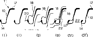
Fig. 6 illustrates the joint forming process in the pass (K-1) in further detail, and this process is divided into following 4 stages substantially.Each position of flange part 10, web portion 12, connector portions 14 only is shown as the U-shaped steel sheet pile 11 of rolling stock.
Among the figure, U-shaped steel sheet pile 11 is shown from the appearance of pass (K-2) when going out in operation (I '); In operation (I), the influence of U-shaped steel sheet pile the place ahead part of the roll that is subjected to nipping, with produce distortion before roll contacts, this mainly causes steel sheet pile to reduce width.Here, " width " refers to the width of U-shaped steel sheet pile integral body.
In operation (II), the collars portion 20 of top roll 18 contacts with the joint outside, makes that width begins to reduce, joint begins bending.
In operation (III), lower roll 22 all produces with joint and contacts, and arrives operation (IV), finishes bending forming by up- down rollers 18,22 depressing of head of butt joint, leaves K-1 in the stage shown in the operation (IV '), obtains the steel sheet pile product.
As shown in Figure 5 and Figure 6, in rolling stock and the symmetrical occasion of shape of product, above-mentioned bending forming is symmetry also, therefore the posture of the rolling stock before and after the roll of nipping about do not produce difference.
But, when rolling stock and the shape of product left and right sides asymmetric occasion, the particularly left and right sides are provided with connector portions asymmetricly, be not bilateral symmetry in flexural deformation perpendicular to the rolling stock in the section of rolling direction.Therefore, behind the roll of nipping the posture of rolling stock about produce difference, become the unstable or diastrophic reason of incomplete joint that causes rolling posture.
Problem of the present invention is to provide a kind of asymmetric steel sheet pile, this asymmetric steel sheet pile has the asymmetric joint geometry in the transverse shape left and right sides, wherein, this asymmetric steel sheet pile has such section configuration, and this section configuration can be so that do not form protuberance in the connector portions of planned sheet pile wall when setting continuously.
Another problem of the present invention is to provide a kind of method with the asymmetric steel sheet pile in the hot rolling manufacturing transverse shape left and right sides, and wherein, the unstable and incomplete joint that can not produce rolling posture when the bending forming of joint is shaped.
Be to provide a kind of bight steel sheet pile and manufacture method thereof in another problem of the present invention, this bight steel sheet pile can be used to have the U-shaped steel sheet pile of asymmetric joint, and can be come clamping by the chuck of pile driver and the time can overlappingly pile up in keeping.
Therefore, the present inventor finds that the opposing party up constitutes the asymmetric joint geometry in the left and right sides under the direction by making, and can engage left and right joint on the extended line of flat part, does not form protuberance on wall.
Yet, in occasion with the asymmetric steel sheet pile of hot rolling manufactured, even the bending forming up to connector portions all is asymmetric shape, promptly use hot rolling to be rolled shaping simultaneously, can not bring special obstacle yet, but in the bending forming stage as the fine finishining rolling process, use when carrying out simultaneously about the roller of pass hole, because the connector portions left and right sides is asymmetric, it is unstable that then rolling as described above posture becomes, bending forming becomes not exclusively, causes stock utilization to descend.
Certainly, in order to solve such problem, can be divided into segmentation one point one point ground by bending forming and carry out anisopleual connector portions, solve the problem of above-mentioned rolling posture, but rolling uneconomical with a plurality of passage one points one point ground, the practicality of can not saying so.
Therefore, when making so asymmetric joint steel sheet pile, be conceived to once left and right joint be carried out bending forming respectively with different roll pass, in the present invention the bending forming that once carries out simultaneously about in the prior art is separately carried out separately, the result learns and can address the above problem effectively, thereby finished the present invention.
In addition, the inventor has made multiple bight steel sheet pile at above-mentioned asymmetric U-shaped steel sheet pile with new joint geometry, sets test.The result shows, by either party of joint bent to the inside, then the steel plate pile lining can be transformed into right angle orientation without special bight steel sheet piles such as T steel sheet piles, thereby finish the present invention.
Now main idea of the present invention is described as follows.(1) a kind of asymmetric steel plate is characterized in that: it comprises the principal part that constitutes the steel sheet pile body, 2 asymmetric joints, connects the arm of above-mentioned principal part and asymmetric joint respectively, and a side joint outwards forms, and the opposing party's joint inwardly forms.(2) as above-mentioned (1) described asymmetric steel sheet pile, above-mentioned arm is parallel to and sets normal or joint and cooperate the extension of axis ground, and above-mentioned arm and asymmetric joint are positioned on the same line at the inner edge of planned sheet pile wall.(3) a kind of manufacture method of asymmetric steel sheet pile is characterized in that: in the course of hot rolling of the steel sheet pile with asymmetric joint geometry, when carrying out the joint bending forming, carry out bending forming fine finishining with the ground butt joint of different concave rolls one side one side respectively.(4) as the manufacture method of above-mentioned (3) described asymmetric steel sheet pile, it is characterized in that: during the joint to a side carried out bending forming fine finishining, the opposing party's joint only was to constrain in the roll pass, did not carry out bending forming.(5) as above-mentioned (1) described asymmetric steel sheet pile, wherein, by with above-mentioned to spigot or to either party of socket towards the lateral bending song, used as the bight steel sheet pile.(6) as above-mentioned (5) described asymmetric steel sheet pile, it is characterized in that: the normal parallel that sets of above-mentioned commissura inwall to spigot and this asymmetric steel sheet pile, or above-mentioned commissura inwall and this asymmetric steel sheet pile to socket to set normal vertical.(7) manufacture method of a kind of bight steel sheet pile, this bight steel sheet pile is asymmetric, a side inside joint is arranged, and the opposing party outside joint is arranged; It is characterized in that: after the steel sheet pile with asymmetric joint is shaped, only have with this steel sheet pile to spigot or to either party of socket towards the operation of inside bend.(8) manufacture method of a kind of bight steel sheet pile, this bight steel sheet pile is asymmetric, a side inside joint is arranged, and the opposing party outside joint is arranged; It is characterized in that: after the steel sheet pile with asymmetric joint is shaped, cutting off in the boundary portion of this joint and arm only with this steel sheet pile to spigot or to either party of socket, then this joint is disposed inwardly, by welding above-mentioned joint and above-mentioned arm are bonded together again.
Fig. 1 is the simplification profile of existing asymmetric U-shaped steel sheet pile.
Fig. 2 (a) and Fig. 2 (b) are respectively the existing asymmetric steel sheet pile of Fig. 1 and the mode declaration pattern specification figure that makes use-case of existing symmetrical steel sheet pile.
Fig. 3 (a) is for illustrating the figure of existing bight steel sheet pile example, and Fig. 3 (b) makes the mode declaration pattern specification figure of use-case for it.
Fig. 4 (a) is for illustrating the figure of existing another bight steel sheet pile example, and Fig. 4 (b) makes the mode declaration pattern specification figure of use-case for it.
Fig. 5 (a) is the rolling mode declaration pattern specification figure with the pass before fine finishining (K-2) in the roll pass of general U-shaped steel sheet pile, and Fig. 5 (b) is the mode declaration pattern specification figure of fine finishining pass (K-1).
Fig. 6 is the mode declaration pattern specification figure of the joint bending forming process in the pass (K-1).
Fig. 7 is the simplification profile of the asymmetric U-shaped steel sheet pile of the present invention.
Fig. 8 is the plan view that illustrates corresponding to the connector portions engagement state of the embodiment of Fig. 7.
Fig. 9 is the plan view that is used to illustrate the method that sets that flat part is clamped.
Figure 10 (a) is the rolling mode declaration pattern specification figure with the pass before the joint bending forming in the roll pass (K-3 ') of the U-shaped steel sheet pile of left and right sides asymmetrical shape, Figure 10 (b) and (c) be the mode declaration pattern specification figure of joint shaping groove (K-2 ', K-1 ').
Figure 11 is the simplification profile that bight of the present invention steel sheet pile example is shown.
Figure 12 for example simplifies profile for another bight steel sheet pile of the present invention is shown.
Figure 13 (a) is for illustrating the key diagram that bight of the present invention steel sheet pile sets example, and Figure 13 (b) is its partial enlarged drawing.
Figure 14 is the key diagram of 1 example of the manufacture method of bight of the present invention steel sheet pile.
Figure 15 is the figure that another example of bight of the present invention steel sheet pile manufacture method is shown.
Figure 16 is the accumulation situation key diagram of bight of the present invention steel sheet pile, and Figure 16 (a) be will be to the spigot occasion of the bight steel sheet pile of bending inwards, and Figure 16 (b) is will be to the occasion of socket towards the bight of lateral bending song steel sheet pile.
Figure 17 (a)~(f) is for illustrating the mode declaration pattern specification figure with the middle rolling stock deformation simulative result of 2 passes that obtain of dimension Finite Element (K-2 ').
Figure 18 is the key diagram at each position of connector portions.
Figure 19 is the key diagram that the construction example of asymmetric steel sheet pile of the present invention and bight steel sheet pile is shown.
, asymmetric steel sheet pile of the present invention and manufacture method thereof are described with reference to the accompanying drawings here, bight steel sheet pile and manufacture method thereof are described then.
Fig. 7 illustrates the global shape of steel sheet pile 30 of an embodiment of the asymmetric U-shaped steel sheet pile of the present invention, and Fig. 8 illustrates its connector portions, and Fig. 9 illustrates by being connected with the planned sheet pile wall 40 that asymmetric U-shaped steel sheet pile forms.
As shown in Figure 7, the principal part of the formation steel sheet pile body of asymmetric U-shaped steel sheet pile 30 be shaped as U-shaped, this steel sheet pile main body is made of web portion 32 and flange part 34, the joint geometry left and right sides of the joint 36,38 at two ends is asymmetric, for example make joint 36 for to spigot, make joint 38 for to socket, the protruding side that makes transverse shape respectively as shown in the example U word side like that all on same direction, thereby can be bonded on the straight line that connects two arms 37, promptly set on the wall.
That is, arm 37 with set normal (among the figure, representing) and equidirectionally be provided with 3 chain-dotted lines, the connector portions that joint 36,38 is bonded with each other is with this arm 37, is arranged on the straight line identical with the inner edge 35 (figure represents with a chain-dotted line) of planned sheet pile wall 40.
In the present embodiment, a side joint 38 outwards forms with respect to the inner edge (being equivalent to digging side front) 35 of planned sheet pile wall 40, and the opposing party's joint 36 inwardly forms, and can be as shown in Figure 8 be bonded together with the shape of the wall of projecting plate pile lining 40 not.In addition, establish projection 39, be used to retrain the rotation at connector portions place at outside joint 38.
For asymmetric U-shaped steel sheet pile 30 of the present invention, when being pressed into machine or vibrating hammer with fluid pressure type and setting, can clamp arm 37 as shown in Figure 9 sets, this arm 37 is parallel to extension with setting direction, and with connector portions on same line, promptly be arranged in (Fig. 7 represents with 2 chain-dotted lines) on the fitted shaft line.That is, owing to become the connector portions and the arm 37 at the center that rotates when setting the flatness skew not taking place, so can prevent the power of setting that acts on clamping section 44 steel sheet pile 30 is rotated.
In addition, even the occasion of obstructions such as rubble is arranged in the ground, also as shown in Figure 9, the arm 37 of asymmetric U-shaped steel sheet pile 30 of the present invention suppresses the effect that the U-shaped steel sheet pile rotates in the ground, twists because the active force on rotation direction (illustrating with blank arrow among the figure) over the ground produces resistance (illustrating with black arrow among the figure) so have.
Carry out an example of the roll pass of hot rolling as U-shaped steel sheet pile to the asymmetric shape in the left and right sides of the present invention, pass before joint bending forming shown in Figure 10 (a)~(c) (K-3 ') and joint bending forming pass (K-2 ', K-1 ').
According to Figure 10 hot bending forming process of the present invention is described below.
At first, such shown in Figure 10 (a), for similarly carrying out the asymmetric steel sheet pile 30 that obtains after the groove rolling with existing method, behind pass K-3 ' adjustment joint thickness with top roll (U.R.) and lower roll (L.R.) and joint height, shown in Figure 10 (b), like that, the joint is for example carried out bending forming with the pass that has top roll (U.R.) and lower roll (L.R.) equally (K-2 ').At this moment, though the distortion left and right sides perpendicular to the steel sheet pile in the section of rolling direction 30 is asymmetric, rolling posture before and after roll is nipped can produce left-right deviation, but carry out bending forming by joint not to the right side, can be suppressed near the imposed deformation of roll bottom dead centre, make the particularly stable posture of outlet side of rolling posture.Therefore, be configured as good joint geometry, keep the opening shape of pass (K-3 ') on the right side at left lateral bending.
Then such shown in Figure 10 (c), with pass (K-1 ') when the right side joint is carried out bending forming, and the roll pass shape that also makes the left side and pass (K-2 ') identical, owing to reason same as described above, can make rolling stable posture, all good joint geometry about the result can obtain.
Here, according to 1 other embodiment of the present invention, during also can carrying out fine finishining at the bending forming to a side joint the opposing party's joint is carried out to a certain degree bending forming, such bending forming is referred to as " crooked in the way " in this manual.
So-called " crooked in the way " for example uses the example of Fig. 6, and just the front end with connector portions erects (operation II).This is because such degree is little to rolling posture influence.In addition,, be meant, under the degree of instability in allowed band of rolling posture, carry out bending forming as in the pass of Figure 10 (b) (K-2 ') in the occasion of Figure 10.
That is, left and right joint bending forming of the present invention is so long as carry out simultaneously getting final product under the condition of substantial bending forming about not.
As the asymmetric steel sheet pile that carries out hot joint bending forming of the present invention, though be to be typical example with the asymmetric U-shaped steel sheet pile of connector portions, the colleague in present technique field should be able to understand that the main position that constitutes the steel sheet pile body is respectively the Z bar sheet pile of Z-shaped, I shape, tubulose, I shape steel sheet pile, tubular steel sheet pile etc. and can carries out bending forming in the fine finishining stage that is shaped to asymmetric connector portions with hot rolling similarly.
Below, describe bight of the present invention steel sheet pile and manufacture method thereof in detail.
Figure 11 and Figure 12 illustrate of the present inventionly to has to spigot 50 with to the example of the bight of socket 52 steel sheet pile 54.Figure 11 is will be to the simplification profile of spigot 50 usefulness welding processing inside bight steel sheet pile 54 at 45, and Figure 12 is the simplification profile with outside joint 52 usefulness welding processing inside bight steel sheet pile 54 at 45.Welding position 56 all respectively blacking represented.
The shape of bight of the present invention steel sheet pile 54 is such: it is based on asymmetric U-shaped steel sheet pile 30 shown in Fig. 7, this U-shaped steel sheet pile 30 1 sides have inside joint 36 (downward pawl), the opposing party has outside joint 38 (pawl that makes progress), have and to be bonded into the transverse shape of linearity towards same direction; As Fig. 7, Figure 11, as shown in Figure 12, either party of the joint 36,38 of this steel sheet pile 30 is at 45 with boundary portion 55 inside (below) bending of joint at the smooth arm 37 of this steel sheet pile.In Fig. 7, be shown in broken lines boundary portion 55, it also is equivalent to the welding position with the occasion of welding manufacturing.
Figure 13 (a) illustrates the situation that cooperates and set bight of the present invention steel sheet pile with connector portions, and this bight steel sheet pile is two steel sheet piles of the type that will bend to spigot and the type that will bend to socket inwardly inwardly.Figure 13 (b) is its enlarged drawing.
As shown in figure 11, by making the inwall 51a of commissura 51 and setting normal (in Figure 11, representing) or cooperating axis (in Figure 11, representing) parallel of steel sheet pile 54 to spigot 50 towards 45 ° of inner bendings with 1 chain-dotted line with 2 chain-dotted lines to spigot 50.
In addition, as shown in figure 12, by with outside joint 52 towards 45 ° of inner bendings, make the inwall 53a of commissura 53 and setting normal (in Figure 12, representing) or cooperating axis (in Figure 12, representing) vertical of steel sheet pile 54 with 1 chain-dotted line with 2 chain-dotted lines to socket 52.
Like this, shown in Figure 13 (a)~(b), above-mentioned 2 kinds of bight steel sheet piles are cooperatively interacted with the joint of bending machining respectively, make setting normal or cooperating intersect vertical axis of each steel sheet pile, can be as the bight of steel plate pile lining.
In the above description, be to be illustrated to will inwardly or inwards carrying out bending machining to socket with welding, as this processing method, all be the asymmetric U-shaped steel sheet pile of elder generation with the oriented spigot of the oriented socket the opposing party of a hot rolling manufacturing side as shown in Figure 7, then either party boundary portion (dotted line part of Fig. 7) of joint and arm is cut off, again this joint is disposed inwardly, with the place of incision of above-mentioned joint of solder joints and above-mentioned arm.Therefore, different with the occasion of existing T shape bight steel sheet pile with welding production, in U-shaped steel sheet pile, do not have useless part substantially, thereby can make with high stock utilization as blank.
In addition, bight of the present invention steel sheet pile can carry out bending machining to the inside with the joint of any one party with U-shaped steel sheet pile of asymmetric connector portions, therefore, also can make by the processing that is shaped of hot rolling or hot and even warm attitude.
Figure 14 example illustrates will be to the inwards crooked situation of socket by hot rolling in the manufacture method of bight of the present invention steel sheet pile, wherein, constitute concave roll by top roll 60 and lower roll 62, be rolled material and use asymmetric U-shaped steel sheet pile 30 that be shaped, shown in Figure 7 in advance, by top and bottom by up-down rollers 60,62 these steel sheet piles 30 of constraint, push export-oriented joint 38 simultaneously from the top, then available 1 passage is shaped.Concave roll can butt joint 38 carry out bending machining by nipping.
In addition, manufacture method as bight of the present invention steel sheet pile, Figure 15 example illustrates by hot and even warm attitude shaping processing and makes the inwards crooked occasion of inside joint, wherein, initial blank material adopts U-shaped steel sheet pile as shown in Figure 7, circumference at steel sheet pile 30 disposes guide roller 64 with its clamping, top and bottom with up-down rollers 66,68 these steel sheet piles 30 of constraint, with roller 70 constraint of left-hand end side to socket 38, top roll 66 by right-hand end pushes inside joint 36 from the top simultaneously, forms with 1 passage.Send the closer locations that preferably such shaping is located at the hot finishing mill rear that is right after asymmetric steel sheet pile 30 with guide roller 64 from the viewpoint that is easy to bending forming.
When setting bight of the present invention steel sheet pile, also can construct by asymmetric U-shaped steel sheet pile of the present invention as shown in Figure 7 the samely, and can clamp web portion or arm when setting machine clamping steel sheet pile, there are not existing T shape and the such problem that can not carry out common clamping of W shape bight steel sheet pile.
What the bending angle of steel plate pile lining (intersecting angle that sets normal of steel sheet pile) was usually maximum is the right angle, but along with the difference of the construction site occasion beyond also having at the angle.But, manufacture method according to bight of the present invention steel sheet pile, by being configured in the angle of finishing mill when changing joint to a side and carry out bending machining nearby or near the guide roller of the position at finishing mill rear, also can making the bight steel sheet pile that can be used in the bight beyond the right angle.
Figure 16 (a) and (b) illustrate the state of stacking bight of the present invention steel sheet pile 54.Figure 16 (a) shows to the bight steel sheet pile that spigot inwards bends, and Figure 16 (b) shows to the inwards crooked bight steel sheet pile of socket.By this figure as can be known, connector portions does not produce interference each other during stacking, does not have stacking posture problem of unstable no matter therefore stack how many pieces yet.
The following describes the manufacture method of asymmetric steel sheet pile of the present invention and bight steel sheet pile
Embodiment.
In order to confirm effect of the present invention, it is rolling that the roll mill that adopts two-dimensional finite element method (2D-FEM) to carry out simulation and use reality has carried out test.
Figure 17 shows the distortion of the rolling stock of the pass K-2 ' (with reference to Figure 10) that adopts the 2D-FEM acquisition.
By result shown in Figure 17 (a)~(f) as can be known, carry out in the process, do not carry out the connector portions of flexural deformation one side (right-hand side when facing Figure 17), comprise flange part 34, arm 37, be restrained in the roll gap, keep original shape the rolling of pass K-2 '.
This is quantitatively concluded, the occasion that (comparative example) compares with the asymmetric connector portions of rolling both sides simultaneously the time, the result is as shown in table 1 below." connector portions height (H) " in the table 1, " connector portions thickness (T) " and " connector portions aperture (G) " are as shown in figure 18.
Also can know thus, respectively asymmetric connector portions be carried out bending forming, for very effective the steel billet total length obtains good connector portions shape this point according to the present invention.
In addition, just come for the anti-heating adhesiveness of the roll at connector portions place this point, the present invention is also effective.
Table 1
| Connector portions dimensional errors (mm) on the steel sheet pile length direction | The heating of connector portions roll adheres to incidence (%) | |||
| Connector portions height (H) | Connector portions thickness (T) | Connector portions aperture (G) | ||
| Example of the present invention | σ=0.5 | σ=0.8 | σ=1.1 | 5.0 |
| Comparative example | σ=1.2 | σ=0.8 | σ=2.7 | 80.0 |
In addition, the result who is tried to roll by the actual use of hot rolling method of the present invention milling train shows, can with good stock utilization obtain above-mentioned have as shown in Figure 7 about products of good joint geometry all.
According to Figure 10 and Figure 15 illustrated like that with hot rolling.Be shaped and make asymmetric steel sheet pile of the present invention and bight steel sheet pile, make up and set asymmetric U-shaped steel sheet pile shown in Figure 7 and Figure 11 and bight shown in Figure 12 steel sheet pile, as the wall body of dwelling house basement.
At first, use the big mill (roughing mill), the intermediate mill that constitute by the dual roll type horizontal roller, and finishing mill totally 3 frames milling train in heating furnace, be heated to 1280 ℃ 250mm thick * the wide continuous casting steel billet of 700mm carries out hot rolling.Dispose 4,3,3 pass respectively at the roll of each milling train.By the reversible rolling of these 3 frames, the shape that material is finish-machined to asymmetric U-shaped steel sheet pile shown in Figure 7 will be rolled.
The manufacturing of bight steel sheet pile as shown in figure 15, employing is arranged on the guide roller and the forming rolls at finishing mill rear, such bight steel sheet pile (A type of 45 ° of bending formings will be inwards made in manufacturing to socket, with reference to Figure 12) and will inwards make such bight steel sheet pile (Type B is with reference to Figure 11) of 45 ° of bending formings to spigot.
On the other hand, enlarge the aperture of above-mentioned guide roller and roll, with same probability (チ ヤ Application ス) made by above-mentioned finishing mill rolling steel sheet pile.
Combination also sets 4 of A type bight steel sheet piles, 4 of the Type B bight steel sheet piles that such usefulness method of the present invention is made respectively, and 30 of asymmetric U-shaped steel sheet piles that constitute the wall body, and the retaining wall of the melt pit used as the dwelling house basement is constructed with wall body.Construction results is shown in Figure 19.Among the figure, the bight steel sheet pile of A type and Type B is represented with A, B simply, in addition is asymmetric steel sheet pile shown in Figure 7.
By Figure 19 also as can be known, vertical 6 (wherein 2 is the bight steel sheet pile) and horizontal 13 (wherein 2 are the bight steel sheet pile).Can successfully be set and problem on not occurring constructing.
According to the present invention, can obtain asymmetric U-shaped steel sheet pile, this asymmetric U-shaped steel sheet pile can be configured in connector portions and straight arm on the face identical with the inner edge of planned sheet pile wall; In addition, with the hot rolling manufacturing such have the U-shaped steel sheet pile of asymmetric joint geometry the time, also can not produce the instability of rolling posture, incomplete joint is shaped, and obtains good joint geometry.
In addition, asymmetric U-shaped steel sheet pile of the present invention and bight steel sheet pile can not produce the problem and the steel sheet pile that clamp and have problems when carrying, keeping when setting, and can on same direction, set continuously, so can save labour and operating expenses effectively by improving efficiency of construction.And, when making the bight steel sheet pile, if a part of cutting off asymmetric U-shaped steel sheet pile is also once more with its welding, then it can be migrated and make the bight steel sheet pile, therefore, do not need big scrap build, only need append the local correction and the guide roller of roll and can make, invention has high industry using value with regard to this point.
Claims (8)
1. asymmetric steel sheet pile, it comprises the principal part that constitutes the steel sheet pile body, 2 asymmetric joints, the arm that connects above-mentioned principal part and asymmetric joint respectively, one side's joint outwards forms, the opposing party's joint inwardly forms, it is characterized in that: above-mentioned arm is parallel to and sets normal or joint and cooperate the extension of axis ground, and above-mentioned arm and asymmetric joint are positioned on the same line at the inner edge of planned sheet pile wall, above-mentioned asymmetric joint is not from the outstanding shape of the wall of planned sheet pile wall, and can mutually combine, be provided with the rotating projection of prevention connector portions in above-mentioned outside joint.
2. the manufacture method of the described asymmetric steel sheet pile of claim 1, it is characterized in that: in the course of hot rolling of steel sheet pile with asymmetric joint geometry, when carrying out the joint bending forming, carry out bending forming processing with the ground butt joint of different concave rolls one side one side respectively.
3. the manufacture method of asymmetric steel sheet pile as claimed in claim 2, it is characterized in that: during the joint to a side carried out bending forming fine finishining, the opposing party's joint only was to constrain in the roll pass, did not carry out bending machining.
4. asymmetric steel sheet pile as claimed in claim 1 is characterized in that, by with above-mentioned to spigot or inwards crooked, used as the bight steel sheet pile to either party of socket.
5. asymmetric steel sheet pile as claimed in claim 4 is characterized in that: above-mentioned to the commissura inwall of spigot and the normal parallel that sets of this asymmetric steel sheet pile.
6. asymmetric steel sheet pile as claimed in claim 4 is characterized in that: above-mentioned commissura inwall to socket and this asymmetric steel sheet pile to set normal vertical.
7. the manufacture method of the described asymmetric steel sheet pile of claim 4 is characterized in that: after the steel sheet pile with asymmetric joint is shaped, only have with this steel sheet pile to spigot or to either party inwards crooked operation of socket.
8. the manufacture method of the described asymmetric steel sheet pile of claim 4, it is characterized in that: after the steel sheet pile with asymmetric joint is shaped, cutting off in the boundary portion of this joint and arm only with this steel sheet pile to spigot or to either party of socket, then this joint is disposed inwardly, by welding above-mentioned joint and above-mentioned arm are bonded together again.
Applications Claiming Priority (6)
| Application Number | Priority Date | Filing Date | Title |
|---|---|---|---|
| JP25327595 | 1995-09-29 | ||
| JP253275/95 | 1995-09-29 | ||
| JP7286198A JP2964933B2 (en) | 1995-07-31 | 1995-11-02 | Underground structure, asymmetric U-shaped sheet pile, and method of placing asymmetric U-shaped sheet pile |
| JP286198/95 | 1995-11-02 | ||
| JP16476196 | 1996-06-25 | ||
| JP164761/96 | 1996-06-25 |
Publications (2)
| Publication Number | Publication Date |
|---|---|
| CN1172517A CN1172517A (en) | 1998-02-04 |
| CN1088486C true CN1088486C (en) | 2002-07-31 |
Family
ID=27322382
Family Applications (1)
| Application Number | Title | Priority Date | Filing Date |
|---|---|---|---|
| CN96191138A Expired - Lifetime CN1088486C (en) | 1995-09-29 | 1996-09-26 | Unsymmetrical steel sheet pile and method for manufacturing the same |
Country Status (8)
| Country | Link |
|---|---|
| EP (1) | EP0795649B1 (en) |
| KR (1) | KR100322317B1 (en) |
| CN (1) | CN1088486C (en) |
| AU (1) | AU695771B2 (en) |
| DE (1) | DE69631950T2 (en) |
| MY (1) | MY120907A (en) |
| TW (1) | TW320573B (en) |
| WO (1) | WO1997013039A1 (en) |
Cited By (2)
| Publication number | Priority date | Publication date | Assignee | Title |
|---|---|---|---|---|
| CN101024955B (en) * | 2002-10-31 | 2010-05-26 | 住友金属工业株式会社 | Sheet type steel pile |
| CN101730610B (en) * | 2007-03-30 | 2012-11-07 | 康特克索股份公司 | Method for the production of sheet piling components, and sheet piling component |
Families Citing this family (21)
| Publication number | Priority date | Publication date | Assignee | Title |
|---|---|---|---|---|
| DE19725143C2 (en) * | 1997-06-13 | 2000-09-21 | Georg Wall | Connecting element for sheet piles |
| AU2012202472B2 (en) * | 1999-12-21 | 2012-09-27 | Tristanagh Pty Ltd | Earth Retention and Piling Systems |
| CA2466537A1 (en) * | 2002-02-14 | 2003-08-21 | Chin Chai Ong | Connector |
| DE102004024103B3 (en) * | 2004-05-14 | 2006-01-05 | Pilepro Llc | Strand-shaped connection profile for connecting sheet piles to support elements |
| EP1698733B1 (en) * | 2005-02-02 | 2010-09-01 | Contexo AG | Sheet pile wall |
| DE202006021127U1 (en) * | 2005-08-09 | 2012-11-23 | Pilepro Llc | Arrangement of sheet pile sections |
| DE202006020607U1 (en) * | 2006-01-17 | 2009-03-19 | Arcelormittal Commercial Rps S.A.R.L. | Sheet pile in double T-shape |
| JP2011084938A (en) * | 2009-10-15 | 2011-04-28 | Nippon Kankyo Seizo Kk | Earth retaining wall and method of constructing the same |
| CN101954397B (en) * | 2010-05-31 | 2011-06-29 | 南京万汇新材料科技有限公司 | Manufacture method of Z-shaped steel sheet pile through continuous cold roll forming |
| JP5764909B2 (en) * | 2010-10-28 | 2015-08-19 | Jfeスチール株式会社 | Steel sheet pile and steel sheet pile wall formed by the steel sheet pile |
| WO2013171910A1 (en) * | 2012-05-16 | 2013-11-21 | Jfeスチール株式会社 | Z-shaped steel sheet pile, and steel sheet pile wall formed from said z-shaped steel sheet pile |
| WO2015159434A1 (en) * | 2014-04-18 | 2015-10-22 | 新日鐵住金株式会社 | Steel sheet pile |
| MX2014012034A (en) * | 2014-10-06 | 2016-04-06 | Armando Javier Ramírez Rascón | Permeable sheet pile and screen for draining underground water and for collecting and conducting surface and underground water. |
| WO2018186379A1 (en) * | 2017-04-03 | 2018-10-11 | 新日鐵住金株式会社 | Method and equipment for manufacturing flanged steel sheet piling |
| CN106981350B (en) * | 2017-05-11 | 2019-06-21 | 江苏瑞恩电气股份有限公司 | A kind of transformer |
| CN109183779A (en) * | 2018-11-08 | 2019-01-11 | 大连大学 | A kind of steel pipe steel plate combination stake building enclosure |
| CN109530431A (en) * | 2018-11-27 | 2019-03-29 | 武汉钢铁有限公司 | The transition milling method of steel sheet pile stable molding |
| JP6791466B1 (en) * | 2019-05-30 | 2020-11-25 | Jfeスチール株式会社 | Steel sheet pile rolling mill guide and steel sheet pile manufacturing method |
| CN111021336A (en) * | 2019-12-31 | 2020-04-17 | 南京图信新材料科技有限公司 | Vertical welding pile and manufacturing method thereof |
| KR102253815B1 (en) * | 2020-12-02 | 2021-05-20 | 건창산업(주) | 3-way thumb pile reinforcement type self-supporting earthen guard |
| KR102261191B1 (en) * | 2020-12-03 | 2021-06-03 | 김규학 | Earth retaining wall |
Family Cites Families (11)
| Publication number | Priority date | Publication date | Assignee | Title |
|---|---|---|---|---|
| FR664775A (en) * | 1927-12-02 | 1929-09-07 | Connection device for iron sheet piles | |
| FR1461552A (en) * | 1965-10-25 | 1966-02-25 | Wendel & Cie De | Cold rolled sheet pile |
| JPS54141007A (en) * | 1978-04-24 | 1979-11-01 | Shinmei Kk | Method of construction of stopping of hill with corner portion and steel sheettpile for corner |
| JPS59166301A (en) * | 1983-03-11 | 1984-09-19 | Kawasaki Steel Corp | Rolling method of larssen type nonsymmetrical u-shaped steel sheet pile |
| JPS6085326U (en) * | 1983-11-10 | 1985-06-12 | 日本鋼管株式会社 | U-shaped steel sheet pile |
| JPH0329378Y2 (en) * | 1986-01-27 | 1991-06-24 | ||
| JPH069682B2 (en) * | 1987-11-19 | 1994-02-09 | 住友金属工業株式会社 | Corner steel sheet pile and manufacturing method thereof |
| JPH0675726B2 (en) * | 1988-07-25 | 1994-09-28 | 新日本製鐵株式会社 | Rolling method of shaped steel by asymmetrical profile box hole die |
| JPH02240319A (en) * | 1989-03-13 | 1990-09-25 | Nkk Corp | Beautified steel sheet pile |
| JPH06280251A (en) * | 1993-03-29 | 1994-10-04 | Sumitomo Metal Ind Ltd | Steel member for underground continuous wall |
| JP3223364B2 (en) * | 1993-12-30 | 2001-10-29 | 株式会社シンコーコーポレーション | Construction sheet pile |
-
1996
- 1996-09-26 KR KR1019970703571A patent/KR100322317B1/en not_active IP Right Cessation
- 1996-09-26 AU AU70953/96A patent/AU695771B2/en not_active Expired
- 1996-09-26 DE DE69631950T patent/DE69631950T2/en not_active Expired - Lifetime
- 1996-09-26 WO PCT/JP1996/002775 patent/WO1997013039A1/en active IP Right Grant
- 1996-09-26 CN CN96191138A patent/CN1088486C/en not_active Expired - Lifetime
- 1996-09-26 EP EP96931991A patent/EP0795649B1/en not_active Expired - Lifetime
- 1996-09-27 MY MYPI96004017A patent/MY120907A/en unknown
- 1996-10-01 TW TW085111968A patent/TW320573B/zh not_active IP Right Cessation
Cited By (2)
| Publication number | Priority date | Publication date | Assignee | Title |
|---|---|---|---|---|
| CN101024955B (en) * | 2002-10-31 | 2010-05-26 | 住友金属工业株式会社 | Sheet type steel pile |
| CN101730610B (en) * | 2007-03-30 | 2012-11-07 | 康特克索股份公司 | Method for the production of sheet piling components, and sheet piling component |
Also Published As
| Publication number | Publication date |
|---|---|
| EP0795649A1 (en) | 1997-09-17 |
| DE69631950D1 (en) | 2004-04-29 |
| AU695771B2 (en) | 1998-08-20 |
| KR100322317B1 (en) | 2002-06-24 |
| EP0795649A4 (en) | 2000-04-26 |
| KR980700494A (en) | 1998-03-30 |
| WO1997013039A1 (en) | 1997-04-10 |
| DE69631950T2 (en) | 2005-02-10 |
| EP0795649B1 (en) | 2004-03-24 |
| CN1172517A (en) | 1998-02-04 |
| MY120907A (en) | 2005-12-30 |
| TW320573B (en) | 1997-11-21 |
| AU7095396A (en) | 1997-04-28 |
Similar Documents
| Publication | Publication Date | Title |
|---|---|---|
| CN1088486C (en) | Unsymmetrical steel sheet pile and method for manufacturing the same | |
| CN100503277C (en) | Rim having a non-uniform thickness and a method for manufacturing the rim | |
| CN1159120C (en) | Method for calibrating U shape steel plate piles | |
| JP4626358B2 (en) | Hat-type steel sheet pile claw bending device | |
| JPS5835761B2 (en) | Rolling method of section steel | |
| JP2006272343A (en) | Method and device for bending claw of hat-type steel sheet piling joint | |
| CN1211170C (en) | Method of rolling sheet and rolling machine | |
| JP2005199293A (en) | Method for manufacturing welded tube having high workability | |
| JPH1071401A (en) | Asymmetrical steel sheet pile and its hot rolling method | |
| JP2004076379A (en) | H-shape steel and its manufacturing method | |
| JP2004322105A (en) | Method for manufacturing wide flange shape and grooved roll | |
| JPH0242567B2 (en) | ||
| JPH0234201A (en) | Method for rolling shape steel by asymmetrical special box-shaped groove roll | |
| JP3494071B2 (en) | Method of manufacturing H-shaped sheet pile | |
| JP2681536B2 (en) | Channel rolling mill row | |
| JPS6410281B2 (en) | ||
| JPH07178404A (en) | Production of shape steel for steel-made continuous wall | |
| JP2861831B2 (en) | Rolling method of constant parallel flange channel steel with external method | |
| JP2023113154A (en) | Method for manufacturing hat-shaped steel sheet pile | |
| JPH10202302A (en) | Grooved bar for welded tube and its manufacture | |
| JP2001353520A (en) | Forming method for square steel tube | |
| JP2577660B2 (en) | Hot rolling method for channel steel | |
| JP3606249B2 (en) | Rolling method of shape steel | |
| SU1389898A1 (en) | Method of manufacturing spirally-welded tubes | |
| JPH04306312A (en) | Linear type shape steel and its manufacture |
Legal Events
| Date | Code | Title | Description |
|---|---|---|---|
| C06 | Publication | ||
| PB01 | Publication | ||
| C10 | Entry into substantive examination | ||
| SE01 | Entry into force of request for substantive examination | ||
| C14 | Grant of patent or utility model | ||
| GR01 | Patent grant | ||
| REG | Reference to a national code |
Ref country code: HK Ref legal event code: GR Ref document number: 1042003 Country of ref document: HK |
|
| CX01 | Expiry of patent term |
Granted publication date: 20020731 |
|
| EXPY | Termination of patent right or utility model |