Disclosure of Invention
In order to overcome the defects that the operation scissors are washed and cleaned manually one by one, the labor intensity is high, the cleaning efficiency is low, the operation scissors need to be rotated during cleaning, the hands are easily cut by the operation scissors carelessly to cause infection, the operation scissors are placed on a tray to be dried, the drying speed is low, and the operation scissors in hospitals are used more intensely, therefore, the technical problem of the invention is that: the surgical scissors flushing device can flush more surgical scissors at one time, can reduce the labor intensity of cleaning personnel, can improve the cleaning efficiency, and can quickly dry the surgical scissors after hands are cleaned.
A surgical scissors flushing device comprises a mounting frame, a collecting frame, a first supporting rod, a first bearing seat, a first rotating shaft, a connecting rod, a spray head, a hose, a first gear, a slide rail, a slide block, a first spring, a rack, a second bearing seat, a second rotating shaft, a sector gear, a motor, a third rotating shaft, a first belt pulley, a first flat belt, a second spring, an inserted rod, a connecting plate, a top plate, a clamping block, a first bolt, a nut, a first clamping block and a second clamping block, wherein the collecting frame is placed on the left side of the lower inner wall of the mounting frame, the lower part of the right inner wall of the mounting frame is connected with the first supporting rod, the left end of the first supporting rod is connected with the first bearing seat, the first rotating shaft is connected in the first bearing seat in an interference manner, the lower part of the left side of the first rotating shaft is connected with the, the top end of the first rotating shaft is connected with a first gear, the middle part of the right inner wall of the mounting frame is connected with a slide rail, the slide rail is provided with a slide block in a sliding manner, a first spring is connected between the right side of the slide block and the right inner wall of the mounting frame, the top end of the slide block is connected with a rack which is positioned at the rear side of the first gear, the rack is meshed with the first gear, the top end of the right wall of the mounting frame is connected with a top plate, the right side of the bottom of the top plate is provided with a second bearing seat, a second rotating shaft is in interference connection with the second bearing seat, the bottom end of the second rotating shaft is connected with a sector gear, the left side of the bottom of the top plate is connected with a motor, an output shaft at the bottom of the motor is connected with a third rotating shaft, the upper part of the third rotating shaft and the upper, the bottom end of the inserting rod is connected with a connecting plate, the connecting plate is located right above the collecting frame, the bottom of the connecting plate is evenly connected with a clamping block, the lower portion of the right side of the clamping block is connected with a first bolt, a nut is screwed on the first bolt, the bottom of the nut is connected with a first stop dog, the bottom of the connecting plate is evenly connected with a second stop dog, and each second stop dog is located right above each nut.
Further, still including drying device, be equipped with drying device on the mounting bracket, drying device is including second branch, the cylinder body, the heating wire, the guide pin bushing, first guide arm, a piston, push rod and third spring, the inner wall left side wall is connected with second branch under the mounting bracket, second branch top is connected with the cylinder body, be equipped with the heating wire in the cylinder body right side wall, the guide pin bushing has been inlayed at cylinder body left side wall middle part, the guide pin bushing inward sliding type is equipped with first guide arm, first guide arm passes the guide pin bushing, first guide arm right-hand member is connected with the piston, first guide arm left end is connected with the push rod, be connected with the third spring between piston left side.
Further, still including the third bearing frame, the fourth pivot, the cam, the second belt pulley, the flat belt of second and baffle, the third bearing frame has been inlayed to cylinder body upper wall left part, interference connection has the fourth pivot in the third bearing frame, fourth pivot bottom is connected with the cam, the cam is located the cylinder body, fourth pivot upper portion and third pivot upper portion all are connected with the second belt pulley, right side second belt pulley is located the first belt pulley in left side top, around having the flat belt of second between the second belt pulley of the left and right sides, the side right part is connected with the baffle on the first guide arm, the baffle is located the cylinder body, the baffle is located the cam left.
Further, the vibrating device comprises a first bulge, a fourth spring, a pressing plate, a second guide rod, a second bulge, a support rod, a guide plate and a second bolt, wherein the left side and the right side of the top of the connecting plate are connected with the first bulge, the left part of the top plate is provided with a through hole, the through hole is positioned on the right side of the motor, the left part of the top plate is connected with the two fourth springs, the two fourth springs are respectively positioned on the left side and the right side of the through hole, the top end of the fourth spring is connected with the pressing plate, the middle part of the bottom of the pressing plate is connected with the second guide rod, the second guide rod penetrates through the through hole, the bottom end of the second guide rod is connected with the second bulge, the second bulge is positioned above the first bulge, the left part of the top plate is connected with the two support rods, the two support rods are respectively positioned on the left side and, the bottom end of the second bolt is contacted with the middle of the top of the pressure plate.
Furthermore, the device also comprises a water outlet pipe and a valve, wherein the water outlet pipe is arranged on the lower part of the left side of the collecting frame and communicated with the collecting frame, and the valve is arranged on the water outlet pipe.
When a user needs to use the equipment to wash the surgical scissors, the user hangs the surgical scissors on the first screw, the user rotates the nut clockwise or anticlockwise for 180 degrees, the nut drives the first stop block to rotate clockwise or anticlockwise for 180 degrees so as to buckle the surgical scissors, the user connects the right end of the hose to the water faucet, the user starts the water faucet, water of the water faucet is conveyed to the spray head from the hose and then is sprayed onto the surgical scissors, the user controls the motor to rotate clockwise, the motor drives the third rotating shaft to rotate clockwise, the third rotating shaft drives the connecting plate and the upper part thereof to rotate clockwise, so that the surgical scissors rotate clockwise, the surgical scissors are cleaned in multiple directions in the rotating process, meanwhile, the third rotating shaft drives the first belt pulley on the left side to rotate clockwise, the first belt pulley on the left side drives the first belt pulley on the right side to rotate clockwise through the first flat belt, the first belt pulley on the right side drives the sector gear to rotate clockwise through the second rotating shaft, when the sector gear is meshed with the first gear, the sector gear drives the first gear to rotate reversely, the first gear drives the rack to move leftwards, the first spring is stretched, the first rotating shaft drives the connecting rod to swing forwards so as to drive the spray head to swing forwards, when the sector gear is not meshed with the first gear, the first spring is reset, the first spring drives the rack to move rightwards, the rack drives the first gear to rotate clockwise, the first rotating shaft drives the connecting rod to swing backwards so as to drive the spray head to swing backwards, the front-back swing of the spray head can be realized, the spray cleaning area of the spray head on the surface of the surgical scissors is enlarged, the collection frame collects sprayed water, when a user finishes cleaning the surgical scissors, the user turns off the water faucet, the spray head stops spraying water, and the user turns off the motor, the third rotating shaft stops rotating, so that the surgical scissors do not rotate any more, the spray head does not swing back and forth any more, a user presses the connecting plate downwards, the connecting plate drives the upper part of the connecting plate to move downwards, thereby driving the surgical scissors to move downwards, the second spring is stretched, the user loosens the connecting plate, the second spring resets, the second spring drives the connecting plate and the upper part thereof to reset upwards, thereby driving the surgical scissors to reset upwards, and the operation is repeated, the moisture on the surgical scissors can be quickly dropped off, when the user dries the surgical scissors in the air, the user with the nut anticlockwise or clockwise rotation 180 degrees, the nut drives first dog anticlockwise or clockwise rotation 180 degrees, the user alright follow first bolt and take out the operation scissors, the user will collect the frame and take out from the mounting bracket to the water that will collect in the frame is poured out, then will collect on the frame puts back the mounting bracket can.
Because still including drying device, be equipped with drying device on the mounting bracket, drying device is including second branch, the cylinder body, the heating wire, the guide pin bushing, first guide arm, a piston, push rod and third spring, the inner wall left wall is connected with second branch under the mounting bracket, second branch top is connected with the cylinder body, be equipped with the heating wire in the cylinder body right side wall, the guide pin bushing has been inlayed at cylinder body left side wall middle part, the guide pin bushing inward sliding type is equipped with first guide arm, first guide arm passes the guide pin bushing, first guide arm right-hand member is connected with the piston, first guide arm left end is connected with the push rod, be connected with the third spring between piston left. After a user cleans surgical scissors by using the device, the user starts the heating wire, the user drives the first guide rod to move leftwards through the push rod, so that the piston is driven to move leftwards, the third spring is compressed, air enters the cylinder body through the heating wire, the user loosens the push rod, the third spring resets, the third spring drives the piston to move rightwards, the air is sprayed onto the surgical scissors from the cylinder body through the heating wire, the operation is repeated, the surgical scissors can be dried, and the user controls the heating wire to stop working after the surgical scissors are dried.
Because still including the third bearing frame, the fourth pivot, the cam, the second belt pulley, the flat belt of second and baffle, the third bearing frame has been inlayed to cylinder body upper wall left part, interference connection has the fourth pivot in the third bearing frame, fourth pivot bottom is connected with the cam, the cam is located the cylinder body, fourth pivot upper portion and third pivot upper portion all are connected with the second belt pulley, the second belt pulley in right side is located the first belt pulley in left side top, around having the flat belt of second between the second belt pulley of the left and right sides, the side right part is connected with the baffle on the first guide arm, the baffle is located the cylinder body, the baffle is located the cam left. When a user finishes cleaning the surgical scissors by using the equipment, the user turns off the water tap, the motor drives the right second belt pulley to rotate through the third rotating shaft, the right second belt pulley drives the left second belt pulley to rotate through the second flat belt, the left second belt pulley drives the cam to rotate through the fourth rotating shaft, when the convex part of the cam is in contact with the baffle, the cam drives the baffle to move leftwards, the baffle drives the first guide rod and the upper part thereof to move leftwards, so as to drive the piston to move leftwards, the third spring is compressed, air is sucked into the cylinder body through the heating wire, when the convex part of the cam is not in contact with the baffle, the third spring is reset, the third spring drives the piston to move rightwards, the air is discharged out of the cylinder body through the heating wire and is blown onto the rotating surgical scissors, the operation is automatically dried by circulating the reciprocating manner, when the surgical scissors are dried, the user turns off the motor.
Because the vibrating device also comprises a vibrating device, the vibrating device comprises a first bulge, a fourth spring, a pressure plate, a second guide rod, a second bulge, a support rod, a guide plate and a second bolt, the first bulge is connected with the left side and the right side of the top of the connecting plate, a through hole is formed in the left part of the top plate, the through hole is positioned at the right side of the motor, the left part of the top plate is connected with the two fourth springs, the two fourth springs are respectively positioned at the left side and the right side of the through hole, the top end of the fourth spring is connected with the pressure plate, the second guide rod penetrates through the through hole, the bottom end of the second guide rod is connected with the second bulge, the second bulge is positioned above the first bulge, the left part of the top plate is connected with the two support rods, the two support rods are respectively positioned at the left side and the right side of the fourth spring at, the bottom end of the second bolt is contacted with the middle of the top of the pressure plate. When a user dries the surgical scissors, the user rotates the second bolt clockwise, the second bolt drives the pressing plate and the upper part of the pressing plate to move downwards, the fourth spring is compressed, when the second protrusion is in contact with the connecting plate, the user stops rotating the second bolt, the connecting plate drives the first protrusion to rotate, when the first protrusion rotates to be in contact with the second protrusion, the second protrusion pushes the first protrusion and the upper part of the first protrusion downwards, the horizontal position of the surgical scissors moves downwards, the second spring is stretched, when the first protrusion rotates away from the second protrusion, the second spring resets, the second spring drives the connecting plate and the upper part of the connecting plate to reset upwards, the horizontal position of the surgical scissors is driven to reset upwards, and the operation is repeated in this way, so that the moisture on the surgical scissors can be dried more quickly while the surgical scissors are dried.
Because still including outlet pipe and valve, the collection frame left side lower part is equipped with the outlet pipe, and the outlet pipe is equipped with the valve with collecting the frame intercommunication on the outlet pipe. When the user finishes the cleaning of the surgical scissors, the user opens the valve, the water in the collecting frame leaks from the water outlet pipe, and when the water in the collecting frame leaks completely, the user closes the valve.
The invention has the advantages that more surgical scissors can be washed at one time, the labor intensity of cleaning personnel can be reduced, the cleaning efficiency can be improved, and the surgical scissors after hands are cleaned can be dried quickly.
Detailed Description
The technical solutions in the embodiments of the present invention will be clearly and completely described below with reference to the drawings in the embodiments of the present invention, and it is obvious that the described embodiments are only a part of the embodiments of the present invention, and not all of the embodiments. All other embodiments, which can be derived by a person skilled in the art from the embodiments given herein without making any creative effort, shall fall within the protection scope of the present invention.
Example 1
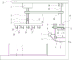
An operating scissors flushing device is shown in figures 1-5 and comprises a mounting frame 1, a collecting frame 2, a first support rod 3, a first bearing seat 4, a first rotating shaft 5, a connecting rod 6, a spray head 7, a hose 8, a first gear 9, a slide rail 10, a slide block 11, a first spring 12, a rack 13, a second bearing seat 14, a second rotating shaft 15, a sector gear 16, a motor 17, a third rotating shaft 18, a first belt pulley 19, a first flat belt 20, a second spring 22, an inserted rod 23, a connecting plate 24, a top plate 25, a clamping block 26, a first bolt 27, a nut 28, a first stop block 29 and a second stop block 30, wherein the collecting frame 2 is placed on the left side of the lower inner wall of the mounting frame 1, the lower portion of the right inner wall of the mounting frame 1 is connected with the first support rod 3, the left end of the first support rod 3 is connected with the first bearing seat 4, the first rotating shaft 5 is in the first bearing seat 4, the left end of the connecting rod 6 is connected with a spray head 7, a hose 8 is arranged on the lower side of the spray head 7, the hose 8 is communicated with the spray head 7, the other end of the hose 8 penetrates through the right wall of the mounting rack 1, the top end of a first rotating shaft 5 is connected with a first gear 9, the middle part of the right inner wall of the mounting rack 1 is connected with a slide rail 10, a slide block 11 is arranged on the slide rail 10 in a sliding mode, a first spring 12 is connected between the right side of the slide block 11 and the right inner wall of the mounting rack 1, the top end of the slide block 11 is connected with a rack 13, the rack 13 is positioned at the rear side of the first gear 9, the rack 13 is meshed with the first gear 9, the top end of the right wall of the mounting rack 1 is connected with a top plate 25, the right side of the bottom of the top plate 25 is provided with a second bearing seat 14, a second rotating shaft 15 is connected in, around having first flat belt 20 between the first belt pulley 19 of the left and right sides, open the lower part of third pivot 18 has recess 21, recess 21 in-connection has second spring 22, the second spring 22 other end is connected with inserted bar 23, inserted bar 23 slidingtype is located recess 21, inserted bar 23 bottom is connected with connecting plate 24, connecting plate 24 is located and collects frame 2 directly over, connecting plate 24 bottom evenly is connected with fixture block 26, fixture block 26 right side lower part all is connected with first bolt 27, all have screwed nut 28 on the first bolt 27, nut 28 bottom all is connected with first dog 29, connecting plate 24 bottom evenly is connected with second dog 30, each second dog 30 all is located directly over each nut 28.
Example 2
An operating scissors flushing device is shown in figures 1-5 and comprises a mounting frame 1, a collecting frame 2, a first support rod 3, a first bearing seat 4, a first rotating shaft 5, a connecting rod 6, a spray head 7, a hose 8, a first gear 9, a slide rail 10, a slide block 11, a first spring 12, a rack 13, a second bearing seat 14, a second rotating shaft 15, a sector gear 16, a motor 17, a third rotating shaft 18, a first belt pulley 19, a first flat belt 20, a second spring 22, an inserted rod 23, a connecting plate 24, a top plate 25, a clamping block 26, a first bolt 27, a nut 28, a first stop block 29 and a second stop block 30, wherein the collecting frame 2 is placed on the left side of the lower inner wall of the mounting frame 1, the lower portion of the right inner wall of the mounting frame 1 is connected with the first support rod 3, the left end of the first support rod 3 is connected with the first bearing seat 4, the first rotating shaft 5 is in the first bearing seat 4, the left end of the connecting rod 6 is connected with a spray head 7, a hose 8 is arranged on the lower side of the spray head 7, the hose 8 is communicated with the spray head 7, the other end of the hose 8 penetrates through the right wall of the mounting rack 1, the top end of a first rotating shaft 5 is connected with a first gear 9, the middle part of the right inner wall of the mounting rack 1 is connected with a slide rail 10, a slide block 11 is arranged on the slide rail 10 in a sliding mode, a first spring 12 is connected between the right side of the slide block 11 and the right inner wall of the mounting rack 1, the top end of the slide block 11 is connected with a rack 13, the rack 13 is positioned at the rear side of the first gear 9, the rack 13 is meshed with the first gear 9, the top end of the right wall of the mounting rack 1 is connected with a top plate 25, the right side of the bottom of the top plate 25 is provided with a second bearing seat 14, a second rotating shaft 15 is connected in, around having first flat belt 20 between the first belt pulley 19 of the left and right sides, open the lower part of third pivot 18 has recess 21, recess 21 in-connection has second spring 22, the second spring 22 other end is connected with inserted bar 23, inserted bar 23 slidingtype is located recess 21, inserted bar 23 bottom is connected with connecting plate 24, connecting plate 24 is located and collects frame 2 directly over, connecting plate 24 bottom evenly is connected with fixture block 26, fixture block 26 right side lower part all is connected with first bolt 27, all have screwed nut 28 on the first bolt 27, nut 28 bottom all is connected with first dog 29, connecting plate 24 bottom evenly is connected with second dog 30, each second dog 30 all is located directly over each nut 28.
The drying device 31 is further included, the drying device 31 is arranged on the mounting frame 1, the drying device 31 comprises a second support rod 311, a cylinder body 312, an electric heating wire 313, a guide sleeve 314, a first guide rod 315, a piston 316, a push rod 317 and a third spring 318, the left wall of the lower inner wall of the mounting frame 1 is connected with the second support rod 311, the top end of the second support rod 311 is connected with the cylinder body 312, the electric heating wire 313 is arranged in the right wall of the cylinder body 312, the guide sleeve 314 is embedded in the middle of the left wall of the cylinder body 312, a first guide rod 315 is arranged in the guide sleeve 314 in a sliding mode, the first guide rod 315 penetrates through the guide sleeve 314, the right end of the first guide rod 315 is connected with the piston 316, the left end of the.
Example 3
An operating scissors flushing device is shown in figures 1-5 and comprises a mounting frame 1, a collecting frame 2, a first support rod 3, a first bearing seat 4, a first rotating shaft 5, a connecting rod 6, a spray head 7, a hose 8, a first gear 9, a slide rail 10, a slide block 11, a first spring 12, a rack 13, a second bearing seat 14, a second rotating shaft 15, a sector gear 16, a motor 17, a third rotating shaft 18, a first belt pulley 19, a first flat belt 20, a second spring 22, an inserted rod 23, a connecting plate 24, a top plate 25, a clamping block 26, a first bolt 27, a nut 28, a first stop block 29 and a second stop block 30, wherein the collecting frame 2 is placed on the left side of the lower inner wall of the mounting frame 1, the lower portion of the right inner wall of the mounting frame 1 is connected with the first support rod 3, the left end of the first support rod 3 is connected with the first bearing seat 4, the first rotating shaft 5 is in the first bearing seat 4, the left end of the connecting rod 6 is connected with a spray head 7, a hose 8 is arranged on the lower side of the spray head 7, the hose 8 is communicated with the spray head 7, the other end of the hose 8 penetrates through the right wall of the mounting rack 1, the top end of a first rotating shaft 5 is connected with a first gear 9, the middle part of the right inner wall of the mounting rack 1 is connected with a slide rail 10, a slide block 11 is arranged on the slide rail 10 in a sliding mode, a first spring 12 is connected between the right side of the slide block 11 and the right inner wall of the mounting rack 1, the top end of the slide block 11 is connected with a rack 13, the rack 13 is positioned at the rear side of the first gear 9, the rack 13 is meshed with the first gear 9, the top end of the right wall of the mounting rack 1 is connected with a top plate 25, the right side of the bottom of the top plate 25 is provided with a second bearing seat 14, a second rotating shaft 15 is connected in, around having first flat belt 20 between the first belt pulley 19 of the left and right sides, open the lower part of third pivot 18 has recess 21, recess 21 in-connection has second spring 22, the second spring 22 other end is connected with inserted bar 23, inserted bar 23 slidingtype is located recess 21, inserted bar 23 bottom is connected with connecting plate 24, connecting plate 24 is located and collects frame 2 directly over, connecting plate 24 bottom evenly is connected with fixture block 26, fixture block 26 right side lower part all is connected with first bolt 27, all have screwed nut 28 on the first bolt 27, nut 28 bottom all is connected with first dog 29, connecting plate 24 bottom evenly is connected with second dog 30, each second dog 30 all is located directly over each nut 28.
The drying device 31 is further included, the drying device 31 is arranged on the mounting frame 1, the drying device 31 comprises a second support rod 311, a cylinder body 312, an electric heating wire 313, a guide sleeve 314, a first guide rod 315, a piston 316, a push rod 317 and a third spring 318, the left wall of the lower inner wall of the mounting frame 1 is connected with the second support rod 311, the top end of the second support rod 311 is connected with the cylinder body 312, the electric heating wire 313 is arranged in the right wall of the cylinder body 312, the guide sleeve 314 is embedded in the middle of the left wall of the cylinder body 312, a first guide rod 315 is arranged in the guide sleeve 314 in a sliding mode, the first guide rod 315 penetrates through the guide sleeve 314, the right end of the first guide rod 315 is connected with the piston 316, the left end of the.
The cylinder body 312 is embedded with the third bearing seat 32 at the left part of the upper wall, the third bearing seat 32 is connected with the fourth rotating shaft 33 in the third bearing seat 32 in an interference mode, the bottom end of the fourth rotating shaft 33 is connected with the cam 34, the cam 34 is located in the cylinder body 312, the upper part of the fourth rotating shaft 33 and the upper part of the third rotating shaft 18 are connected with the second belt pulley 35, the right second belt pulley 35 is located above the left first belt pulley 19, the second flat belt 36 is wound between the second belt pulleys 35 on the left side and the right side, the baffle 37 is connected to the right part on the upper side of the first guide rod 315, the baffle 37 is located in the cylinder body 312, and the baffle 37 is located on the left side of the cam 34.
Example 4
An operating scissors flushing device is shown in figures 1-5 and comprises a mounting frame 1, a collecting frame 2, a first support rod 3, a first bearing seat 4, a first rotating shaft 5, a connecting rod 6, a spray head 7, a hose 8, a first gear 9, a slide rail 10, a slide block 11, a first spring 12, a rack 13, a second bearing seat 14, a second rotating shaft 15, a sector gear 16, a motor 17, a third rotating shaft 18, a first belt pulley 19, a first flat belt 20, a second spring 22, an inserted rod 23, a connecting plate 24, a top plate 25, a clamping block 26, a first bolt 27, a nut 28, a first stop block 29 and a second stop block 30, wherein the collecting frame 2 is placed on the left side of the lower inner wall of the mounting frame 1, the lower portion of the right inner wall of the mounting frame 1 is connected with the first support rod 3, the left end of the first support rod 3 is connected with the first bearing seat 4, the first rotating shaft 5 is in the first bearing seat 4, the left end of the connecting rod 6 is connected with a spray head 7, a hose 8 is arranged on the lower side of the spray head 7, the hose 8 is communicated with the spray head 7, the other end of the hose 8 penetrates through the right wall of the mounting rack 1, the top end of a first rotating shaft 5 is connected with a first gear 9, the middle part of the right inner wall of the mounting rack 1 is connected with a slide rail 10, a slide block 11 is arranged on the slide rail 10 in a sliding mode, a first spring 12 is connected between the right side of the slide block 11 and the right inner wall of the mounting rack 1, the top end of the slide block 11 is connected with a rack 13, the rack 13 is positioned at the rear side of the first gear 9, the rack 13 is meshed with the first gear 9, the top end of the right wall of the mounting rack 1 is connected with a top plate 25, the right side of the bottom of the top plate 25 is provided with a second bearing seat 14, a second rotating shaft 15 is connected in, around having first flat belt 20 between the first belt pulley 19 of the left and right sides, open the lower part of third pivot 18 has recess 21, recess 21 in-connection has second spring 22, the second spring 22 other end is connected with inserted bar 23, inserted bar 23 slidingtype is located recess 21, inserted bar 23 bottom is connected with connecting plate 24, connecting plate 24 is located and collects frame 2 directly over, connecting plate 24 bottom evenly is connected with fixture block 26, fixture block 26 right side lower part all is connected with first bolt 27, all have screwed nut 28 on the first bolt 27, nut 28 bottom all is connected with first dog 29, connecting plate 24 bottom evenly is connected with second dog 30, each second dog 30 all is located directly over each nut 28.
The drying device 31 is further included, the drying device 31 is arranged on the mounting frame 1, the drying device 31 comprises a second support rod 311, a cylinder body 312, an electric heating wire 313, a guide sleeve 314, a first guide rod 315, a piston 316, a push rod 317 and a third spring 318, the left wall of the lower inner wall of the mounting frame 1 is connected with the second support rod 311, the top end of the second support rod 311 is connected with the cylinder body 312, the electric heating wire 313 is arranged in the right wall of the cylinder body 312, the guide sleeve 314 is embedded in the middle of the left wall of the cylinder body 312, a first guide rod 315 is arranged in the guide sleeve 314 in a sliding mode, the first guide rod 315 penetrates through the guide sleeve 314, the right end of the first guide rod 315 is connected with the piston 316, the left end of the.
The cylinder body 312 is embedded with the third bearing seat 32 at the left part of the upper wall, the third bearing seat 32 is connected with the fourth rotating shaft 33 in the third bearing seat 32 in an interference mode, the bottom end of the fourth rotating shaft 33 is connected with the cam 34, the cam 34 is located in the cylinder body 312, the upper part of the fourth rotating shaft 33 and the upper part of the third rotating shaft 18 are connected with the second belt pulley 35, the right second belt pulley 35 is located above the left first belt pulley 19, the second flat belt 36 is wound between the second belt pulleys 35 on the left side and the right side, the baffle 37 is connected to the right part on the upper side of the first guide rod 315, the baffle 37 is located in the cylinder body 312, and the baffle 37 is located on the left side of the cam 34.
The shaking device 38 further comprises a shaking device 38, the shaking device 38 comprises a first protrusion 381, a fourth spring 382, a pressing plate 383, a second guide rod 384, a second protrusion 386, a support rod 387, a guide plate 388 and a second bolt 3810, the first protrusion 381 is connected to the left and right sides of the top of the connecting plate 24, a through hole 385 is formed in the left portion of the top plate 25, the through hole 385 is located on the right of the motor 17, the two fourth springs 382 are respectively located on the left and right sides of the through hole 385, the pressing plate 383 is connected to the top end of the fourth spring 382, the second guide rod 384 is connected to the middle of the bottom of the pressing plate 383, the second guide rod 384 penetrates through the through hole 385, the second protrusion 386 is connected to the bottom end of the second guide rod 384, the second protrusion 386 is located above the first protrusion 381, the left portion of the top plate 25 is connected with the two support rods 387, the two support rods 387 are respectively located on the left and right, the middle part of the guide plate 388 is provided with a threaded hole 389, a second bolt 3810 is screwed in the threaded hole 389, and the bottom end of the second bolt 3810 is contacted with the middle of the top of the pressing plate 383.
The device also comprises a water outlet pipe 39 and a valve 40, wherein the water outlet pipe 39 is arranged at the lower part of the left side of the collecting frame 2, the water outlet pipe 39 is communicated with the collecting frame 2, and the valve 40 is arranged on the water outlet pipe 39.
When a user needs to use the device to wash the surgical scissors, the user hangs the surgical scissors on the first screw, the user rotates the nut 28 clockwise or anticlockwise for 180 degrees, the nut 28 drives the first stop block 29 to rotate clockwise or anticlockwise for 180 degrees, so as to buckle the surgical scissors, the user connects the right end of the hose 8 to the water faucet, the user starts the water faucet, water of the water faucet is conveyed from the hose 8 to the spray head 7 and then is sprayed onto the surgical scissors, the user controls the motor 17 to rotate clockwise, the motor 17 drives the third rotating shaft 18 to rotate clockwise, the third rotating shaft 18 drives the connecting plate 24 and the upper parts thereof to rotate clockwise, so that the surgical scissors rotate clockwise, the surgical scissors are cleaned in multiple directions in the rotating process, meanwhile, the third rotating shaft 18 drives the left first belt pulley 19 to rotate clockwise, the left first belt pulley 19 drives the right first belt pulley 19 to rotate clockwise through the first flat belt 20, the first belt pulley 19 on the right drives the sector gear 16 to rotate clockwise through the second rotating shaft 15, when the sector gear 16 is meshed with the first gear 9, the sector gear 16 drives the first gear 9 to rotate reversely, the first gear 9 drives the rack 13 to move leftwards, the first spring 12 is stretched, the first rotating shaft 5 drives the connecting rod 6 to swing forwards, so as to drive the spray head 7 to swing forwards, when the sector gear 16 is not meshed with the first gear 9, the first spring 12 is reset, the first spring 12 drives the rack 13 to move rightwards, the rack 13 drives the first gear 9 to rotate clockwise, the first rotating shaft 5 drives the connecting rod 6 to swing backwards, so as to drive the spray head 7 to swing backwards, in this way, the front-back swing of the spray head 7 can be realized, the spray cleaning area of the spray head 7 on the surface of the surgical scissors is enlarged, the collecting frame 2 collects sprayed water, when the user finishes cleaning the surgical scissors, when the user turns off the water faucet, the spray head 7 stops spraying water, the user turns off the motor 17, the third rotating shaft 18 stops rotating, so that the surgical scissors do not rotate any more, meanwhile, the spray head 7 does not swing back and forth, the user presses the connecting plate 24 downwards, the connecting plate 24 drives the upper part of the connecting plate to move downwards, so that the surgical scissors are driven to move downwards, the second spring 22 is stretched, the user loosens the connecting plate 24, the second spring 22 resets, the second spring 22 drives the connecting plate 24 and the upper part of the connecting plate to reset upwards, so that the surgical scissors are driven to reset upwards, the steps are repeated, the moisture on the surgical scissors can be quickly released, when the user dries the surgical scissors in the air, the user rotates the nut 28 anticlockwise or clockwise by 180 degrees, the nut 28 drives the first stop block 29 to rotate the anticlockwise or clockwise by 180 degrees, the user can take out the surgical scissors from the first bolt 27, the user takes, and pour out the water of collecting in the frame 2, then will collect on frame 2 puts back the mounting bracket 1 can.
Because the drying device 31 is further included, the drying device 31 is arranged on the mounting frame 1, the drying device 31 includes a second support rod 311, a cylinder body 312, an electric heating wire 313, a guide sleeve 314, a first guide rod 315, a piston 316, a push rod 317 and a third spring 318, the left wall of the lower inner wall of the mounting frame 1 is connected with the second support rod 311, the top end of the second support rod 311 is connected with the cylinder body 312, the electric heating wire 313 is arranged in the right wall of the cylinder body 312, the guide sleeve 314 is embedded in the middle of the left wall of the cylinder body 312, the first guide rod 315 is arranged in the guide sleeve 314 in a sliding mode, the first guide rod 315 penetrates through the guide sleeve 314, the right end of the first guide rod 315 is connected with the piston 316, the left end of the. After the user cleans the surgical scissors by using the device, the user starts the heating wire 313, the user drives the first guide rod 315 to move leftward through the push rod 317, so as to drive the piston 316 to move leftward, the third spring 318 is compressed, air enters the cylinder 312 through the heating wire 313, the user releases the push rod 317, the third spring 318 resets, the third spring 318 drives the piston 316 to move rightward, the air is sprayed on the surgical scissors from the cylinder 312 through the heating wire 313, and the operation is repeated in this way, so that the surgical scissors can be dried, and after the surgical scissors are dried, the user controls the heating wire 313 to stop working.
Because still including third bearing frame 32, fourth pivot 33, cam 34, second belt pulley 35, the flat belt of second 36 and baffle 37, third bearing frame 32 has been inlayed to cylinder body 312 upper wall left part, interference connection has fourth pivot 33 in the third bearing frame 32, fourth pivot 33 bottom is connected with cam 34, cam 34 is located cylinder body 312, fourth pivot 33 upper portion and third pivot 18 upper portion all are connected with second belt pulley 35, right side second belt pulley 35 is located the first belt pulley 19 in left side top, it has the flat belt of second 36 to wind between the second belt pulley 35 of the left and right sides, the upside right part of first guide arm 315 is connected with baffle 37, baffle 37 is located cylinder body 312, baffle 37 is located cam 34 left. When the user finishes cleaning the surgical scissors by using the device, the user turns off the water tap, the motor 17 drives the right second belt pulley 35 to rotate through the third rotating shaft 18, the right second belt pulley 35 drives the left second belt pulley 35 to rotate through the second flat belt 36, the left second belt pulley 35 drives the cam 34 to rotate through the fourth rotating shaft 33, when the convex part of the cam 34 contacts with the baffle 37, the cam 34 drives the baffle 37 to move leftwards, the baffle 37 drives the first guide rod 315 and the upper part thereof to move leftwards, so as to drive the piston 316 to move leftwards, the third spring 318 is compressed, air is sucked into the cylinder 312 through the heating wire 313, when the convex part of the cam 34 does not contact with the baffle 37, the third spring 318 resets, the third spring 318 drives the piston 316 to move rightwards, the air is discharged out of the cylinder 312 through the heating wire 313, is blown onto the rotating surgical scissors, and the operation is repeated in such a cycle, the automatic drying of the surgical scissors can be realized, and when the surgical scissors are dried, the motor 17 is turned off by a user.
Because the shaking device 38 is further included, the shaking device 38 includes a first protrusion 381, a fourth spring 382, a pressing plate 383, a second guide rod 384, a second protrusion 386, a support rod 387, a guide plate 388 and a second bolt 3810, the first protrusion 381 is connected to the left and right sides of the top of the connecting plate 24, the through hole 385 is formed at the left portion of the top plate 25, the through hole 385 is located at the right side of the motor 17, the two fourth springs 382 are respectively located at the left and right sides of the through hole 385, the pressing plate 383 is connected to the top end of the fourth spring 382, the second guide rod 384 is connected to the middle of the bottom of the pressing plate 383, the second guide rod 384 passes through the through hole 385, the second protrusion 386 is connected to the bottom end of the second guide rod 384, the second protrusion 386 is located above the first protrusion 381, the left portion of the top plate 25 is connected to the two support rods 387, the two support rods 387 are respectively located at the left and right sides of, the middle part of the guide plate 388 is provided with a threaded hole 389, a second bolt 3810 is screwed in the threaded hole 389, and the bottom end of the second bolt 3810 is contacted with the middle of the top of the pressing plate 383. When the user dries the surgical scissors, the user rotates the second bolt 3810 clockwise, the second bolt 3810 drives the pressing plate 383 and the upper part thereof to move downwards, the fourth spring 382 is compressed, when the second protrusion 386 contacts the connecting plate 24, the user stops rotating the second bolt 3810, the connecting plate 24 drives the first protrusion 381 to rotate, when the first projection 381 is rotated to be brought into contact with the second projection 386, the second projection 386 pushes the first projection 381 and its upper member downward, so that the horizontal position of the surgical scissors moves downwards, the second spring 22 is stretched, when the first protrusion 381 rotates away from the second protrusion 386, the second spring 22 resets, the second spring 22 drives the connecting plate 24 and the upper part thereof to reset upwards, so as to drive the horizontal position of the surgical scissors to reset upwards, and in this way, the drying device can dry the surgical scissors and dry the moisture on the surgical scissors more quickly.
Because the collecting device also comprises a water outlet pipe 39 and a valve 40, the lower part of the left side of the collecting frame 2 is provided with the water outlet pipe 39, the water outlet pipe 39 is communicated with the collecting frame 2, and the valve 40 is arranged on the water outlet pipe 39. When the user finishes cleaning the surgical scissors, the user opens the valve 40, the water in the collecting frame 2 leaks out from the water outlet pipe 39, and when the water in the collecting frame 2 leaks out completely, the user closes the valve 40.
It should be understood that the above description is for exemplary purposes only and is not meant to limit the present invention. Those skilled in the art will appreciate that variations of the present invention are intended to be included within the scope of the claims herein.