CN108472138B - Devices, systems, and methods for transcatheter treatment of valve regurgitation - Google Patents
Devices, systems, and methods for transcatheter treatment of valve regurgitation Download PDFInfo
- Publication number
- CN108472138B CN108472138B CN201680077877.8A CN201680077877A CN108472138B CN 108472138 B CN108472138 B CN 108472138B CN 201680077877 A CN201680077877 A CN 201680077877A CN 108472138 B CN108472138 B CN 108472138B
- Authority
- CN
- China
- Prior art keywords
- assistance device
- coaptation assistance
- struts
- annulus
- coaptation
- Prior art date
- Legal status (The legal status is an assumption and is not a legal conclusion. Google has not performed a legal analysis and makes no representation as to the accuracy of the status listed.)
- Active
Links
- 238000000034 method Methods 0.000 title abstract description 128
- 238000011282 treatment Methods 0.000 title abstract description 7
- 206010067171 Regurgitation Diseases 0.000 title description 6
- 210000003709 heart valve Anatomy 0.000 claims abstract description 21
- 210000002216 heart Anatomy 0.000 claims description 63
- 239000003550 marker Substances 0.000 claims description 17
- 229910001000 nickel titanium Inorganic materials 0.000 claims description 14
- 230000013011 mating Effects 0.000 claims description 13
- HLXZNVUGXRDIFK-UHFFFAOYSA-N nickel titanium Chemical compound [Ti].[Ti].[Ti].[Ti].[Ti].[Ti].[Ti].[Ti].[Ti].[Ti].[Ti].[Ni].[Ni].[Ni].[Ni].[Ni].[Ni].[Ni].[Ni].[Ni].[Ni].[Ni].[Ni].[Ni].[Ni] HLXZNVUGXRDIFK-UHFFFAOYSA-N 0.000 claims description 11
- 206010027727 Mitral valve incompetence Diseases 0.000 abstract description 25
- 238000002513 implantation Methods 0.000 abstract description 7
- 210000001519 tissue Anatomy 0.000 description 46
- 210000004115 mitral valve Anatomy 0.000 description 40
- 230000002861 ventricular Effects 0.000 description 36
- 239000007943 implant Substances 0.000 description 27
- 238000004873 anchoring Methods 0.000 description 25
- 239000000463 material Substances 0.000 description 25
- 210000002837 heart atrium Anatomy 0.000 description 20
- 230000008901 benefit Effects 0.000 description 19
- 230000001746 atrial effect Effects 0.000 description 16
- 210000005246 left atrium Anatomy 0.000 description 16
- 210000005240 left ventricle Anatomy 0.000 description 16
- 239000008280 blood Substances 0.000 description 13
- 210000004369 blood Anatomy 0.000 description 13
- 238000001356 surgical procedure Methods 0.000 description 13
- 230000017531 blood circulation Effects 0.000 description 12
- 210000003484 anatomy Anatomy 0.000 description 11
- 230000007246 mechanism Effects 0.000 description 11
- 238000004519 manufacturing process Methods 0.000 description 7
- 238000002560 therapeutic procedure Methods 0.000 description 7
- 230000008859 change Effects 0.000 description 6
- 230000006870 function Effects 0.000 description 6
- 210000005245 right atrium Anatomy 0.000 description 6
- 210000005241 right ventricle Anatomy 0.000 description 6
- 210000000591 tricuspid valve Anatomy 0.000 description 6
- 230000005540 biological transmission Effects 0.000 description 5
- 230000003412 degenerative effect Effects 0.000 description 5
- 230000000694 effects Effects 0.000 description 5
- 239000010410 layer Substances 0.000 description 5
- 210000003540 papillary muscle Anatomy 0.000 description 5
- 230000008569 process Effects 0.000 description 5
- 208000012287 Prolapse Diseases 0.000 description 4
- 230000009471 action Effects 0.000 description 4
- 210000003698 chordae tendineae Anatomy 0.000 description 4
- 210000003748 coronary sinus Anatomy 0.000 description 4
- 230000008878 coupling Effects 0.000 description 4
- 238000010168 coupling process Methods 0.000 description 4
- 238000005859 coupling reaction Methods 0.000 description 4
- 201000010099 disease Diseases 0.000 description 4
- 208000037265 diseases, disorders, signs and symptoms Diseases 0.000 description 4
- 229920000295 expanded polytetrafluoroethylene Polymers 0.000 description 4
- 210000005003 heart tissue Anatomy 0.000 description 4
- 208000015181 infectious disease Diseases 0.000 description 4
- 210000003516 pericardium Anatomy 0.000 description 4
- BASFCYQUMIYNBI-UHFFFAOYSA-N platinum Chemical compound [Pt] BASFCYQUMIYNBI-UHFFFAOYSA-N 0.000 description 4
- 230000000717 retained effect Effects 0.000 description 4
- 229920004934 Dacron® Polymers 0.000 description 3
- 206010019280 Heart failures Diseases 0.000 description 3
- 210000001765 aortic valve Anatomy 0.000 description 3
- QVGXLLKOCUKJST-UHFFFAOYSA-N atomic oxygen Chemical compound [O] QVGXLLKOCUKJST-UHFFFAOYSA-N 0.000 description 3
- 230000008602 contraction Effects 0.000 description 3
- -1 e.g. Inorganic materials 0.000 description 3
- 210000003191 femoral vein Anatomy 0.000 description 3
- 238000002594 fluoroscopy Methods 0.000 description 3
- 238000003780 insertion Methods 0.000 description 3
- 230000037431 insertion Effects 0.000 description 3
- 210000004072 lung Anatomy 0.000 description 3
- 229910052760 oxygen Inorganic materials 0.000 description 3
- 239000001301 oxygen Substances 0.000 description 3
- 239000005020 polyethylene terephthalate Substances 0.000 description 3
- 210000003102 pulmonary valve Anatomy 0.000 description 3
- 238000007789 sealing Methods 0.000 description 3
- 239000002356 single layer Substances 0.000 description 3
- 238000012800 visualization Methods 0.000 description 3
- 102000008186 Collagen Human genes 0.000 description 2
- 108010035532 Collagen Proteins 0.000 description 2
- 208000005189 Embolism Diseases 0.000 description 2
- 208000001953 Hypotension Diseases 0.000 description 2
- 239000004698 Polyethylene Substances 0.000 description 2
- 239000004743 Polypropylene Substances 0.000 description 2
- SMWDFEZZVXVKRB-UHFFFAOYSA-N Quinoline Chemical compound N1=CC=CC2=CC=CC=C21 SMWDFEZZVXVKRB-UHFFFAOYSA-N 0.000 description 2
- 208000001435 Thromboembolism Diseases 0.000 description 2
- 210000000709 aorta Anatomy 0.000 description 2
- 210000001367 artery Anatomy 0.000 description 2
- 238000005452 bending Methods 0.000 description 2
- 210000005242 cardiac chamber Anatomy 0.000 description 2
- 230000000747 cardiac effect Effects 0.000 description 2
- 229920001436 collagen Polymers 0.000 description 2
- 238000013270 controlled release Methods 0.000 description 2
- 230000001419 dependent effect Effects 0.000 description 2
- 239000003814 drug Substances 0.000 description 2
- 230000004064 dysfunction Effects 0.000 description 2
- 230000002708 enhancing effect Effects 0.000 description 2
- 230000003628 erosive effect Effects 0.000 description 2
- 239000000835 fiber Substances 0.000 description 2
- 239000012530 fluid Substances 0.000 description 2
- 239000006261 foam material Substances 0.000 description 2
- 230000004927 fusion Effects 0.000 description 2
- 208000018578 heart valve disease Diseases 0.000 description 2
- 238000003384 imaging method Methods 0.000 description 2
- 238000011065 in-situ storage Methods 0.000 description 2
- 238000010329 laser etching Methods 0.000 description 2
- 230000005012 migration Effects 0.000 description 2
- 238000013508 migration Methods 0.000 description 2
- 208000005907 mitral valve insufficiency Diseases 0.000 description 2
- 238000012986 modification Methods 0.000 description 2
- 230000004048 modification Effects 0.000 description 2
- 238000012544 monitoring process Methods 0.000 description 2
- 229910052697 platinum Inorganic materials 0.000 description 2
- 229920000573 polyethylene Polymers 0.000 description 2
- 229920001155 polypropylene Polymers 0.000 description 2
- 210000003492 pulmonary vein Anatomy 0.000 description 2
- 230000008707 rearrangement Effects 0.000 description 2
- 230000008439 repair process Effects 0.000 description 2
- 125000006850 spacer group Chemical group 0.000 description 2
- 229910001220 stainless steel Inorganic materials 0.000 description 2
- 239000010935 stainless steel Substances 0.000 description 2
- 230000000153 supplemental effect Effects 0.000 description 2
- XLYOFNOQVPJJNP-UHFFFAOYSA-N water Substances O XLYOFNOQVPJJNP-UHFFFAOYSA-N 0.000 description 2
- 241000283690 Bos taurus Species 0.000 description 1
- 208000032170 Congenital Abnormalities Diseases 0.000 description 1
- 206010067660 Heart valve incompetence Diseases 0.000 description 1
- 206010020880 Hypertrophy Diseases 0.000 description 1
- MWCLLHOVUTZFKS-UHFFFAOYSA-N Methyl cyanoacrylate Chemical compound COC(=O)C(=C)C#N MWCLLHOVUTZFKS-UHFFFAOYSA-N 0.000 description 1
- 208000003430 Mitral Valve Prolapse Diseases 0.000 description 1
- 229920005830 Polyurethane Foam Polymers 0.000 description 1
- FAPWRFPIFSIZLT-UHFFFAOYSA-M Sodium chloride Chemical compound [Na+].[Cl-] FAPWRFPIFSIZLT-UHFFFAOYSA-M 0.000 description 1
- 208000007536 Thrombosis Diseases 0.000 description 1
- 201000001943 Tricuspid Valve Insufficiency Diseases 0.000 description 1
- 206010044640 Tricuspid valve incompetence Diseases 0.000 description 1
- 230000002159 abnormal effect Effects 0.000 description 1
- 230000001154 acute effect Effects 0.000 description 1
- 239000003242 anti bacterial agent Substances 0.000 description 1
- 238000013459 approach Methods 0.000 description 1
- 229910052788 barium Inorganic materials 0.000 description 1
- DSAJWYNOEDNPEQ-UHFFFAOYSA-N barium atom Chemical compound [Ba] DSAJWYNOEDNPEQ-UHFFFAOYSA-N 0.000 description 1
- 230000003115 biocidal effect Effects 0.000 description 1
- 230000000903 blocking effect Effects 0.000 description 1
- 210000004204 blood vessel Anatomy 0.000 description 1
- 230000002612 cardiopulmonary effect Effects 0.000 description 1
- 230000001684 chronic effect Effects 0.000 description 1
- 150000001875 compounds Chemical class 0.000 description 1
- 230000006835 compression Effects 0.000 description 1
- 238000007906 compression Methods 0.000 description 1
- 229940039231 contrast media Drugs 0.000 description 1
- 239000002872 contrast media Substances 0.000 description 1
- 230000007423 decrease Effects 0.000 description 1
- 239000002934 diuretic Substances 0.000 description 1
- 229940030606 diuretics Drugs 0.000 description 1
- 229940079593 drug Drugs 0.000 description 1
- 238000002651 drug therapy Methods 0.000 description 1
- 229910000701 elgiloys (Co-Cr-Ni Alloy) Inorganic materials 0.000 description 1
- 238000001839 endoscopy Methods 0.000 description 1
- 238000005516 engineering process Methods 0.000 description 1
- 239000006260 foam Substances 0.000 description 1
- 238000002695 general anesthesia Methods 0.000 description 1
- PCHJSUWPFVWCPO-UHFFFAOYSA-N gold Chemical compound [Au] PCHJSUWPFVWCPO-UHFFFAOYSA-N 0.000 description 1
- 229910052737 gold Inorganic materials 0.000 description 1
- 239000010931 gold Substances 0.000 description 1
- 230000035876 healing Effects 0.000 description 1
- 230000004217 heart function Effects 0.000 description 1
- 229920001903 high density polyethylene Polymers 0.000 description 1
- 239000004700 high-density polyethylene Substances 0.000 description 1
- 230000036543 hypotension Effects 0.000 description 1
- 238000000338 in vitro Methods 0.000 description 1
- 238000002347 injection Methods 0.000 description 1
- 239000007924 injection Substances 0.000 description 1
- 208000014674 injury Diseases 0.000 description 1
- 230000001788 irregular Effects 0.000 description 1
- 230000002262 irrigation Effects 0.000 description 1
- 238000003973 irrigation Methods 0.000 description 1
- 230000007774 longterm Effects 0.000 description 1
- 208000012866 low blood pressure Diseases 0.000 description 1
- 206010025482 malaise Diseases 0.000 description 1
- 229910052751 metal Inorganic materials 0.000 description 1
- 239000002184 metal Substances 0.000 description 1
- 230000000116 mitigating effect Effects 0.000 description 1
- 238000003032 molecular docking Methods 0.000 description 1
- 210000003205 muscle Anatomy 0.000 description 1
- 230000007935 neutral effect Effects 0.000 description 1
- 210000000056 organ Anatomy 0.000 description 1
- 210000004789 organ system Anatomy 0.000 description 1
- 230000002093 peripheral effect Effects 0.000 description 1
- 210000004303 peritoneum Anatomy 0.000 description 1
- 238000011458 pharmacological treatment Methods 0.000 description 1
- 239000004033 plastic Substances 0.000 description 1
- 229920003023 plastic Polymers 0.000 description 1
- 210000004224 pleura Anatomy 0.000 description 1
- 239000004417 polycarbonate Substances 0.000 description 1
- 229920000515 polycarbonate Polymers 0.000 description 1
- 229920000728 polyester Polymers 0.000 description 1
- 229920001296 polysiloxane Polymers 0.000 description 1
- 239000011496 polyurethane foam Substances 0.000 description 1
- 210000001147 pulmonary artery Anatomy 0.000 description 1
- 238000005086 pumping Methods 0.000 description 1
- 125000001567 quinoxalinyl group Chemical class N1=C(C=NC2=CC=CC=C12)* 0.000 description 1
- 230000004044 response Effects 0.000 description 1
- 238000009958 sewing Methods 0.000 description 1
- 229920000431 shape-memory polymer Polymers 0.000 description 1
- 239000011780 sodium chloride Substances 0.000 description 1
- 239000003381 stabilizer Substances 0.000 description 1
- 238000012546 transfer Methods 0.000 description 1
- 230000008733 trauma Effects 0.000 description 1
- 230000000472 traumatic effect Effects 0.000 description 1
- 230000001960 triggered effect Effects 0.000 description 1
- 238000002604 ultrasonography Methods 0.000 description 1
- 230000002792 vascular Effects 0.000 description 1
- 210000005166 vasculature Anatomy 0.000 description 1
- 229940124549 vasodilator Drugs 0.000 description 1
- 239000003071 vasodilator agent Substances 0.000 description 1
- 210000003462 vein Anatomy 0.000 description 1
- 210000001631 vena cava inferior Anatomy 0.000 description 1
- 210000000596 ventricular septum Anatomy 0.000 description 1
- 230000000007 visual effect Effects 0.000 description 1
Images


Classifications
-
- A—HUMAN NECESSITIES
- A61—MEDICAL OR VETERINARY SCIENCE; HYGIENE
- A61F—FILTERS IMPLANTABLE INTO BLOOD VESSELS; PROSTHESES; DEVICES PROVIDING PATENCY TO, OR PREVENTING COLLAPSING OF, TUBULAR STRUCTURES OF THE BODY, e.g. STENTS; ORTHOPAEDIC, NURSING OR CONTRACEPTIVE DEVICES; FOMENTATION; TREATMENT OR PROTECTION OF EYES OR EARS; BANDAGES, DRESSINGS OR ABSORBENT PADS; FIRST-AID KITS
- A61F2/00—Filters implantable into blood vessels; Prostheses, i.e. artificial substitutes or replacements for parts of the body; Appliances for connecting them with the body; Devices providing patency to, or preventing collapsing of, tubular structures of the body, e.g. stents
- A61F2/02—Prostheses implantable into the body
- A61F2/24—Heart valves ; Vascular valves, e.g. venous valves; Heart implants, e.g. passive devices for improving the function of the native valve or the heart muscle; Transmyocardial revascularisation [TMR] devices; Valves implantable in the body
- A61F2/2442—Annuloplasty rings or inserts for correcting the valve shape; Implants for improving the function of a native heart valve
- A61F2/2454—Means for preventing inversion of the valve leaflets, e.g. chordae tendineae prostheses
-
- A—HUMAN NECESSITIES
- A61—MEDICAL OR VETERINARY SCIENCE; HYGIENE
- A61B—DIAGNOSIS; SURGERY; IDENTIFICATION
- A61B17/00—Surgical instruments, devices or methods
- A61B17/064—Surgical staples, i.e. penetrating the tissue
-
- A—HUMAN NECESSITIES
- A61—MEDICAL OR VETERINARY SCIENCE; HYGIENE
- A61B—DIAGNOSIS; SURGERY; IDENTIFICATION
- A61B17/00—Surgical instruments, devices or methods
- A61B17/068—Surgical staplers, e.g. containing multiple staples or clamps
-
- A—HUMAN NECESSITIES
- A61—MEDICAL OR VETERINARY SCIENCE; HYGIENE
- A61F—FILTERS IMPLANTABLE INTO BLOOD VESSELS; PROSTHESES; DEVICES PROVIDING PATENCY TO, OR PREVENTING COLLAPSING OF, TUBULAR STRUCTURES OF THE BODY, e.g. STENTS; ORTHOPAEDIC, NURSING OR CONTRACEPTIVE DEVICES; FOMENTATION; TREATMENT OR PROTECTION OF EYES OR EARS; BANDAGES, DRESSINGS OR ABSORBENT PADS; FIRST-AID KITS
- A61F2/00—Filters implantable into blood vessels; Prostheses, i.e. artificial substitutes or replacements for parts of the body; Appliances for connecting them with the body; Devices providing patency to, or preventing collapsing of, tubular structures of the body, e.g. stents
- A61F2/02—Prostheses implantable into the body
- A61F2/24—Heart valves ; Vascular valves, e.g. venous valves; Heart implants, e.g. passive devices for improving the function of the native valve or the heart muscle; Transmyocardial revascularisation [TMR] devices; Valves implantable in the body
- A61F2/2427—Devices for manipulating or deploying heart valves during implantation
-
- A—HUMAN NECESSITIES
- A61—MEDICAL OR VETERINARY SCIENCE; HYGIENE
- A61F—FILTERS IMPLANTABLE INTO BLOOD VESSELS; PROSTHESES; DEVICES PROVIDING PATENCY TO, OR PREVENTING COLLAPSING OF, TUBULAR STRUCTURES OF THE BODY, e.g. STENTS; ORTHOPAEDIC, NURSING OR CONTRACEPTIVE DEVICES; FOMENTATION; TREATMENT OR PROTECTION OF EYES OR EARS; BANDAGES, DRESSINGS OR ABSORBENT PADS; FIRST-AID KITS
- A61F2/00—Filters implantable into blood vessels; Prostheses, i.e. artificial substitutes or replacements for parts of the body; Appliances for connecting them with the body; Devices providing patency to, or preventing collapsing of, tubular structures of the body, e.g. stents
- A61F2/02—Prostheses implantable into the body
- A61F2/24—Heart valves ; Vascular valves, e.g. venous valves; Heart implants, e.g. passive devices for improving the function of the native valve or the heart muscle; Transmyocardial revascularisation [TMR] devices; Valves implantable in the body
- A61F2/2442—Annuloplasty rings or inserts for correcting the valve shape; Implants for improving the function of a native heart valve
- A61F2/2463—Implants forming part of the valve leaflets
-
- A—HUMAN NECESSITIES
- A61—MEDICAL OR VETERINARY SCIENCE; HYGIENE
- A61F—FILTERS IMPLANTABLE INTO BLOOD VESSELS; PROSTHESES; DEVICES PROVIDING PATENCY TO, OR PREVENTING COLLAPSING OF, TUBULAR STRUCTURES OF THE BODY, e.g. STENTS; ORTHOPAEDIC, NURSING OR CONTRACEPTIVE DEVICES; FOMENTATION; TREATMENT OR PROTECTION OF EYES OR EARS; BANDAGES, DRESSINGS OR ABSORBENT PADS; FIRST-AID KITS
- A61F2/00—Filters implantable into blood vessels; Prostheses, i.e. artificial substitutes or replacements for parts of the body; Appliances for connecting them with the body; Devices providing patency to, or preventing collapsing of, tubular structures of the body, e.g. stents
- A61F2/02—Prostheses implantable into the body
- A61F2/24—Heart valves ; Vascular valves, e.g. venous valves; Heart implants, e.g. passive devices for improving the function of the native valve or the heart muscle; Transmyocardial revascularisation [TMR] devices; Valves implantable in the body
- A61F2/2442—Annuloplasty rings or inserts for correcting the valve shape; Implants for improving the function of a native heart valve
- A61F2/2466—Delivery devices therefor
-
- A—HUMAN NECESSITIES
- A61—MEDICAL OR VETERINARY SCIENCE; HYGIENE
- A61B—DIAGNOSIS; SURGERY; IDENTIFICATION
- A61B17/00—Surgical instruments, devices or methods
- A61B17/064—Surgical staples, i.e. penetrating the tissue
- A61B2017/0649—Coils or spirals
-
- A—HUMAN NECESSITIES
- A61—MEDICAL OR VETERINARY SCIENCE; HYGIENE
- A61F—FILTERS IMPLANTABLE INTO BLOOD VESSELS; PROSTHESES; DEVICES PROVIDING PATENCY TO, OR PREVENTING COLLAPSING OF, TUBULAR STRUCTURES OF THE BODY, e.g. STENTS; ORTHOPAEDIC, NURSING OR CONTRACEPTIVE DEVICES; FOMENTATION; TREATMENT OR PROTECTION OF EYES OR EARS; BANDAGES, DRESSINGS OR ABSORBENT PADS; FIRST-AID KITS
- A61F2210/00—Particular material properties of prostheses classified in groups A61F2/00 - A61F2/26 or A61F2/82 or A61F9/00 or A61F11/00 or subgroups thereof
- A61F2210/0014—Particular material properties of prostheses classified in groups A61F2/00 - A61F2/26 or A61F2/82 or A61F9/00 or A61F11/00 or subgroups thereof using shape memory or superelastic materials, e.g. nitinol
-
- A—HUMAN NECESSITIES
- A61—MEDICAL OR VETERINARY SCIENCE; HYGIENE
- A61F—FILTERS IMPLANTABLE INTO BLOOD VESSELS; PROSTHESES; DEVICES PROVIDING PATENCY TO, OR PREVENTING COLLAPSING OF, TUBULAR STRUCTURES OF THE BODY, e.g. STENTS; ORTHOPAEDIC, NURSING OR CONTRACEPTIVE DEVICES; FOMENTATION; TREATMENT OR PROTECTION OF EYES OR EARS; BANDAGES, DRESSINGS OR ABSORBENT PADS; FIRST-AID KITS
- A61F2220/00—Fixations or connections for prostheses classified in groups A61F2/00 - A61F2/26 or A61F2/82 or A61F9/00 or A61F11/00 or subgroups thereof
- A61F2220/0008—Fixation appliances for connecting prostheses to the body
- A61F2220/0016—Fixation appliances for connecting prostheses to the body with sharp anchoring protrusions, e.g. barbs, pins, spikes
-
- A—HUMAN NECESSITIES
- A61—MEDICAL OR VETERINARY SCIENCE; HYGIENE
- A61F—FILTERS IMPLANTABLE INTO BLOOD VESSELS; PROSTHESES; DEVICES PROVIDING PATENCY TO, OR PREVENTING COLLAPSING OF, TUBULAR STRUCTURES OF THE BODY, e.g. STENTS; ORTHOPAEDIC, NURSING OR CONTRACEPTIVE DEVICES; FOMENTATION; TREATMENT OR PROTECTION OF EYES OR EARS; BANDAGES, DRESSINGS OR ABSORBENT PADS; FIRST-AID KITS
- A61F2250/00—Special features of prostheses classified in groups A61F2/00 - A61F2/26 or A61F2/82 or A61F9/00 or A61F11/00 or subgroups thereof
- A61F2250/0058—Additional features; Implant or prostheses properties not otherwise provided for
- A61F2250/0096—Markers and sensors for detecting a position or changes of a position of an implant, e.g. RF sensors, ultrasound markers
- A61F2250/0098—Markers and sensors for detecting a position or changes of a position of an implant, e.g. RF sensors, ultrasound markers radio-opaque, e.g. radio-opaque markers
Landscapes
- Health & Medical Sciences (AREA)
- Cardiology (AREA)
- Life Sciences & Earth Sciences (AREA)
- General Health & Medical Sciences (AREA)
- Public Health (AREA)
- Biomedical Technology (AREA)
- Heart & Thoracic Surgery (AREA)
- Engineering & Computer Science (AREA)
- Veterinary Medicine (AREA)
- Animal Behavior & Ethology (AREA)
- Vascular Medicine (AREA)
- Oral & Maxillofacial Surgery (AREA)
- Transplantation (AREA)
- Surgery (AREA)
- Molecular Biology (AREA)
- Nuclear Medicine, Radiotherapy & Molecular Imaging (AREA)
- Medical Informatics (AREA)
- Prostheses (AREA)
- Paper (AREA)
- Manufacturing Of Magnetic Record Carriers (AREA)
Abstract
The present invention relates to devices for transcatheter treatment of mitral regurgitation, in particular to coaptation assistance devices for implantation through a valve; a system comprising the coaptation assistance device and an anchor for implantation; a system comprising the coaptation assistance device and a delivery catheter; and methods for transcatheter implantation of a coaptation device through a heart valve.
Description
Cross Reference to Related Applications
The present application claims priority as a continuation of U.S. application No. 15/153480 filed 2016, 5, 12, 35u.s.c. § 120, which in turn claims priority as a non-provisional application No. 62/252336 filed 2015, 11, 6, 2015, according to 35u.s.c. § 119(e), the disclosure of each of the foregoing applications being incorporated herein by reference in its entirety and made a part of the present specification.
Background
FIELD
The present disclosure generally provides improved medical devices, systems and methods typically for treating heart valve disease and/or for altering the characteristics of one or more valves of the body. Embodiments include implants for treating mitral regurgitation.
The human heart receives blood from organs and tissues via veins, pumps the blood through the lungs where it becomes oxygen-rich, and pushes the oxygenated blood away from the heart to arteries so that the body's organ system can extract oxygen for proper function. The deoxygenated blood flows back to the heart where it is pumped again to the lungs.
The heart includes four chambers: the Right Atrium (RA), Right Ventricle (RV), Left Atrium (LA) and Left Ventricle (LV). The pumping action on the left and right sides of the heart occurs generally synchronously during the overall cardiac cycle.
The heart has four valves that are typically configured to selectively deliver blood flow in the correct direction during the cardiac cycle. The valve that separates the atrium from the ventricle is called the atrioventricular (or AV) valve. The AV valve between the left atrium and left ventricle is the mitral valve. The AV valve between the right atrium and right ventricle is the tricuspid valve. The pulmonary valve directs blood flow to the pulmonary arteries and thence to the lungs; the blood returns to the left atrium via the pulmonary veins. The aortic valve directs blood flow through the aorta and thence to the periphery. There is usually no direct connection between the ventricles or between the atria.
Mechanical heart beats are triggered by electrical impulses that propagate throughout the heart tissue. The opening and closing of the heart valve may occur primarily due to pressure differences between the chambers, which may result from passive filling or chamber contraction. For example, opening and closing of the mitral valve may occur due to a pressure difference between the left atrium and the left ventricle.
At the beginning of ventricular filling (diastole), the aortic and pulmonary valves close to prevent backflow from the arteries into the ventricle. Immediately thereafter, the AV valve opens to allow unimpeded flow from the atria into the respective ventricles. Immediately after ventricular contraction (i.e., ventricular emptying) begins, the tricuspid and mitral valves typically close, forming a seal that prevents flow from the ventricles back into the respective atria.
Unfortunately, the AV valve may be damaged or may not function properly, resulting in an abnormal closure. AV valves are complex structures that typically include the annulus (annuus), leaflets (leaflets), chordae (chord), and support structures. Each atrium is connected to its valves via the atrial vestibulum. The mitral valve has two leaflets; a similar structure of the tricuspid valve has three leaflets, and apposition or coaptation of the respective surfaces of the leaflets towards each other helps provide closure or sealing of the valve to prevent blood flow in the wrong direction. Failure of the leaflets to seal during ventricular systole is known as malcoaptation (malcoaptation) and may allow blood to flow back through the valve (regurgitation). Heart valve regurgitation can have serious consequences for the patient, often resulting in heart failure, reduced blood flow, low blood pressure, and/or reduced oxygen flow to body tissues. Mitral regurgitation can also cause blood to flow back from the left atrium into the pulmonary veins, causing congestion. Severe valve regurgitation, if left untreated, can result in permanent disability or death.
Description of the related Art
Various therapies have been applied to treat mitral valve regurgitation, and other therapies have still been proposed but have not been practically used to treat patients. While several known therapies have been found to provide benefits to at least some patients, further options are still needed. For example, medicaments (such as diuretics and vasodilators) may be used in patients with mild mitral regurgitation to help reduce the amount of blood that regurgitates into the left atrium. However, drug therapy may lack patient compliance. Many patients may occasionally (or even regularly) fail medication despite the potential severity of chronic and/or increasingly worsening mitral regurgitation. Pharmacological treatment of mitral regurgitation can also be inconvenient, often ineffective (especially as the situation worsens), and may be associated with serious side effects (such as hypotension).
Various surgical options have also been proposed and/or used to treat mitral regurgitation. For example, open-heart surgery (open-heart surgery) may replace or repair a dysfunctional mitral valve. In annuloplasty (annuloplasty) ring repair, the posterior mitral annulus may be reduced in size along its circumference, optionally using sutures passed through a mechanical surgical annuloplasty sewing ring to provide coaptation. Open surgery may also seek to reshape the leaflets and/or remodel the support structure. In any event, open mitral valve surgery (open mitral valve surgery) is generally a very invasive treatment that is performed on a cardiopulmonary machine with the patient under general anesthesia and the chest being cut. Complications can be common and given the morbidity (and potential mortality) of open-heart surgery, scheduling becomes a difficult problem-more ill patients may require surgery at best, but are less able to survive surgery. Successful open mitral valve surgery results can also be very dependent on surgical skill and experience.
In view of morbidity and mortality from open-heart surgery, innovators have sought less invasive surgical therapies. Methods performed robotically or by endoscopy are still often quite invasive and can also be time consuming, expensive, and in at least some cases, very dependent on the skill of the operator. It would be desirable to make even less traumatic to these sometimes infirm patients, and it would also be desirable to provide a therapy that can be successfully administered by a large number of physicians using a widely varying technique. To this end, a variety of techniques and methods have been proposed which are said to be less invasive. These include devices that seek to reshape the mitral annulus from within the coronary sinus; devices that attempt to reshape the annulus by tying the native valve ring from top to bottom; a device to fuse leaflets (mimicking an alfiri suture); devices that reshape the left ventricle, etc.
A variety of perhaps the best known mitral valve replacement implants have been developed that generally replace (or displace) the native leaflets and rely on surgically implanted structures to control the blood flow path between heart chambers. While these various methods and tools meet various levels of certainty, none have been widely recognized as an ideal treatment for most or all patients suffering from mitral regurgitation.
Due to the difficulties and disadvantages of known minimally invasive mitral valve regurgitation therapies and implants, still alternative treatments have been proposed. Some alternative proposals require the implanted structure to remain within the annulus throughout the heart cycle. One group of these proposals includes cylindrical balloons or the like that remain implanted on a cord or rigid rod that extends between the atrium and ventricle through the valve opening. Another group relies on arcuate ring structures or the like, often in combination with structural cross members or buttons extending through the valve wall to anchor the implant. Unfortunately, sealing between the native leaflets and the entire perimeter of the balloon or other coaxial body can prove challenging, while if the arch wall or stabilizer interconnecting cross-member is flexed, significant contraction around the native annulus during each heartbeat can lead to significant fatigue failure tissue during long-term implantation. Furthermore, significant movement of the valve tissue can make accurate positioning of the implant difficult, regardless of whether the implant is rigid or flexible.
In view of the above, it is desirable to provide improved medical devices, systems and methods. It would be particularly desirable to provide new techniques for treating mitral regurgitation and other heart valve diseases, and/or for altering the characteristics of one or more of the other valves of the body. There remains a need for a device that can directly augment leaflet coaptation (rather than indirectly via annular or ventricular reshaping) and that does not disrupt leaflet anatomy via fusion or other means, but that can be simply and reliably deployed without excessive cost or procedure time. It would be particularly advantageous if these new techniques could be implemented using less invasive methods without the need to stop the heart or rely on a heart-lung machine for deployment, and without the need to rely on the superior technique of the operator, thereby providing improved valve and/or heart function.
SUMMARY
The present disclosure generally provides improved medical devices, systems, and methods. Novel coaptation assistance devices, systems, and methods for treating mitral regurgitation and other valve diseases are disclosed. The coaptation assistance device can remain within the blood flow path as the valve moves back and forth between the open valve configuration and the closed valve configuration. The coaptation assistance device can be a relatively thin, elongate (along the blood flow path), and/or conformable structure that extends laterally across some, most, or all of the width of the valve opening, allowing coaptation between at least one of the native leaflets and the coaptation assistance device. The devices described herein may be used with any valve of the human body, including valves having two leaflets or three leaflets.
In some embodiments, one advantage is the ability to retract the coaptation assistance device. In some embodiments, the coaptation assistance device has a single anchor that can engage or disengage tissue. In some embodiments, the anchor is captured within an annular liner of the coaptation assistance device. In some embodiments, the captured anchor is removed at the same time the coaptation assistance device is removed. In some embodiments, the coaptation assistance device can include a secondary anchor. In some embodiments, the coaptation assistance device can include a passive anchor. In some embodiments, the engagement of the anchors with the tissue disposes one or more passive anchors into engagement with the tissue. In some embodiments, one advantage is the retrieval of the coaptation assistance device during a procedure. In some embodiments, the coaptation assistance device can be repositioned during the surgical procedure. In some embodiments, the coaptation assistance device can be removed from the patient during a subsequent surgical procedure. In some embodiments, the coaptation assistance device can be replaced with another device during a subsequent surgical procedure. In some embodiments, a single annulus anchor facilitates the ability to retrieve the coaptation assistance device. In some embodiments, the position of the annulus anchor facilitates the ability to retract the coaptation assistance device. In some embodiments, the ability to fold the coaptation assistance device using purse-string sutures (pull-string sutures) as described herein facilitates the ability to retract the coaptation assistance device.
In some embodiments, one advantage is the connection between the coaptation assistance device and the delivery catheter. In some embodiments, the coaptation assistance device includes an annular liner having features to engage the delivery catheter. In some embodiments, the coaptation assistance device and the delivery catheter are removably coupled such that the coaptation assistance device can be released from the delivery catheter during a procedure. In some embodiments, the one or more secondary structures couple the coaptation assistance device and the delivery catheter after the coaptation assistance device is released from the delivery catheter. In some embodiments, the one or more secondary structures comprise cinch cord type sutures as described herein. In some embodiments, one or more secondary structures facilitate folding and/or unfolding of the coaptation assistance device. In some embodiments, the coaptation assistance device and the delivery catheter are rotationally fixed relative to each other when coupled. In some embodiments, relative movement of the delivery catheter causes movement of the coaptation assistance device.
In some embodiments, one advantage is that the coaptation assistance device can be delivered with a hub-guided orientation. In some methods of use, the annular liner may be moved into position relative to the anatomy. In some methods of use, the ventricular end of the coaptation assistance device can remain within the delivery catheter until the annular liner is deployed. In some methods of use, once the annular liner and/or annular anchor are engaged with tissue, the coaptation assistance device can be deployed. In some methods of use, once the annular liner and/or annular anchor are engaged with tissue, the ventricular end of the coaptation assistance device can be deployed.
In some embodiments, one advantage is that the coaptation assistance device can be delivered with a strut-guided orientation. In this method of use, one or more of the struts of the coaptation assistance device can be moved into position relative to the anatomy prior to placement of the annular liner. In some methods of use, the coaptation assistance device can be deployed or partially deployed prior to engagement of the annulus anchor. In some methods of use, the annular liner may be retained within the delivery catheter until one or more of the struts are disposed. In some methods of use, once the struts are deployed, the annulus anchor may engage the tissue.
In some embodiments, one advantage is that the annulus anchor can rotate independently of the coaptation assistance device. As described herein, a coaptation assistance device is coupled with a portion of a delivery catheter. As described herein, the annulus anchor is independently coupled with another portion of the delivery catheter, such as a driver disposed with the delivery catheter. The annulus anchor may rotate independently of the annular bushing. The annular liner may remain stationary when the annulus anchor is rotated to engage tissue. The annulus anchor can be driven into tissue while the delivery catheter maintains the position of the annular liner.
In some embodiments, one advantage is the ability to fold the coaptation assistance device. In some embodiments, the coaptation assistance device is fully folded. The fully folded configuration may be an insertion configuration or a low profile configuration. In some embodiments, the coaptation assistance device is partially folded. The partially folded configuration may be a partially deployed configuration. The partially folded configuration may enable selective deployment of the coaptation assistance device within the heart. The partially folded configuration may allow the coaptation assistance device to be moved to a position within the heart. The configuration of the coaptation assistance device can be monitored, for example, by imaging, to ensure proper deployment. In some embodiments, one or more purse string-type sutures or portions thereof are pulled tight to fold or partially fold the coaptation assistance device. In some embodiments, the partially folded configuration can allow rotation of the coaptation assistance device. In some embodiments, the fully collapsed configuration may allow for rotation of the coaptation assistance device. In some embodiments, the coaptation assistance device can be rotated with the delivery catheter or a portion thereof. In some embodiments, the coaptation assistance device can rotate about a central location, such as an annular bushing.
In some embodiments, one advantage is the ability to deploy the coaptation assistance device. In some embodiments, one or more purse string-type sutures or portions thereof are loosened to deploy the coaptation assistance device. In some embodiments, the loosening of purse string-type sutures causes one or more struts to assume an intermediate configuration. In some embodiments, the loosening of purse string-type sutures causes one or more struts to assume a pre-formed curve. In some embodiments, one or more of the pillars comprises NiTi. In some embodiments, purse string-type sutures may be repeatedly tightened and/or loosened. In some embodiments, purse string-type sutures are captured within the coaptation assistance device. In some embodiments, the cinch pocket draws a cinch-cord type suture to remove the coaptation assistance device from the patient. In some embodiments, the purse string-type suture is released to deploy the coaptation assistance device within the heart of the patient. In some embodiments, a cinch-cord type suture may be selectively deployed to deploy one portion of the coaptation assistance device while another portion of the coaptation assistance device remains folded or partially folded.
In some embodiments, one advantage is the ability to adjust the coaptation assistance device. In some embodiments, the coaptation assistance device can be supported by a central location. In some embodiments, the central location is an anchor. In some embodiments, the central location is a bushing. In some embodiments, the hub and/or anchor are generally located near the diametrical midpoint of the coaptation assistance device. In some embodiments, the hub and/or anchor are generally located near a midpoint and/or central location of the annular portion of the coaptation assistance device. In some embodiments, the coaptation assistance device can be supported at an intermediate position. In some embodiments, the coaptation assistance device can be rotated by rotating a delivery catheter connected to an annular hub. In some embodiments, the coaptation assistance device can be moved longitudinally by corresponding longitudinal movement of a delivery catheter connected to the annular hub.
In some embodiments, one advantage is that the coaptation assistance device can be retained by the delivery catheter after deployment of the coaptation assistance device. In some embodiments, the coaptation assistance device can be fully deployed within the mitral valve, but still tethered to the delivery catheter. In some embodiments, the coaptation assistance device can be adjusted after it is fully deployed within the mitral valve. In some embodiments, after the coaptation assistance device is fully deployed, the coaptation assistance device can be rotated about the hub. In some embodiments, the anchor can disengage and/or re-engage with tissue after the coaptation assistance device is fully deployed. In some embodiments, the cinch-cord type suture may fold and/or unfold the coaptation assistance device, or a portion thereof, after the coaptation assistance device is fully deployed. In some embodiments, after the coaptation assistance device is fully deployed, the coaptation assistance device can be recaptured. In some embodiments, after the coaptation assistance device is fully deployed, the coaptation assistance device can be removed.
In some embodiments, one advantage is that the coaptation assistance device does not require ventricular attachment. In some embodiments, the coaptation assistance device only requires annulus attachment. In some embodiments, the coaptation assistance device requires only attachment of the annulus anchor through the annular liner. In some embodiments, the coaptation assistance device only requires attachment of the annulus anchor through the annular liner and the annulus barb. In some embodiments, the coaptation assistance device only requires attachment of the annulus anchor through the annular liner, annulus barb, and/or commissure barb.
In some embodiments, one advantage is a radially extending frame. In some embodiments, the frame includes an annular liner and one or more struts. In some embodiments, the struts extend radially from the annular liner. In some embodiments, the frame is constructed from a single planar sheet of material. In some embodiments, the frame is precisely cut using water jet, laser etching, or similar techniques. In some embodiments, the frame is constructed by forming an annular liner with an edge of the frame. In some embodiments, the planar sheet of material is formed into a ring, which becomes an annular bushing. In some embodiments, the struts are bent into a desired configuration. In some embodiments, the struts are evenly spaced around the circumference of the annular liner. In some embodiments, the struts are unevenly spaced about the circumference of the annular liner. In some embodiments, the struts extending along a portion of the circumference of the annular liner are different than the struts extending along another portion of the circumference of the annular liner. In some embodiments, one or more designated portions of the strut are designed to be placed in proximity to an annulus region of the heart. In some embodiments, one or more designated portions of the struts are designed to be placed near the commissure regions of the heart. In some embodiments, one or more designated portions of the struts are designed to be placed near a ventricular region of the heart. In some embodiments, the struts of the radially outward frame do not intersect. In some embodiments, the struts of the radially outward frame do not form a mesh. In some embodiments, the struts of the radially outward frame extend along a line from the hub to an edge of the coaptation assistance device. In some embodiments, the struts of the radially outward frame have sharp edges. In some embodiments, the sharp edge extends along a straight line from an edge of the coaptation assistance device. In some embodiments, the sharp edge is integrally formed within the post. In some embodiments, the struts of the radially outward frame have one, two, or more radii of curvature. In some embodiments, the struts of the radially outward frame may be concave or convex or both concave and convex along the length of the struts. In some embodiments, the struts of the radially outward frame have one or more inflection points.
In some embodiments, one advantage is the bending of the frame. In some embodiments, the annular liner extends radially. In some embodiments, the annular liner extends from the coaptation assistance device away from the annulus. In some embodiments, the annular bushing extends from a surface of the coaptation assistance device above a plane of the strut. In some embodiments, the edges of the coaptation assistance device are curved. In some embodiments, one or more struts may curve laterally from the annular liner toward the upper edge. In some embodiments, the upper edge of the coaptation assistance device can curve upward from the annulus. In some embodiments, the upper edge of the coaptation assistance device can curve upward from the posterior leaflet. In some embodiments, the upper edge of the coaptation assistance device can curve downward toward the annulus. In some embodiments, the upper edge of the coaptation assistance device can curve downward toward the posterior leaflet. In some embodiments, one or more struts may curve laterally from the annular liner toward the lower edge. In some embodiments, the lower edge of the coaptation assistance device can curve away from the posterior leaflet. In some embodiments, the lower edge of the coaptation assistance device can be curved toward the posterior leaflet.
In some embodiments, a coaptation assistance device for treating poor coaptation of a heart valve is provided. The heart valve has an annulus. The coaptation assistance device can include a body including an annular portion and a coaptation portion. In some embodiments, the ring portion is configured to be implanted within the heart over the annulus. In some embodiments, the coaptation region is configured to be implanted within the heart and transect the plane of the annulus. The coaptation assistance device can include a first coaptation surface and an opposing second coaptation surface. In some embodiments, each surface is bounded by a first side edge, a second side edge, a lower edge, and an upper edge. In some embodiments, the upper edge forms a flange (lip) and is cupped downward toward the lower edge or upward from the annular portion. The coaptation assistance device can include a hub and an anchor coupled to the hub and supported by the annular portion. In some embodiments, the anchor is selectively deployable at a first target location. The coaptation assistance device can include a plurality of struts extending radially outward from the hub. In some embodiments, the plurality of struts includes at least a first strut located within the loop portion and a second strut extending from the loop portion to the apposition portion, wherein the second strut has an overall length that is longer than an overall length of the first strut, such as, for example, an overall length that is about or at least about 110%, 120%, 130%, 140%, 150%, 160%, 170%, 180%, 190%, 200%, 225%, 250% or more of the overall length of the first strut. In some embodiments, the total length of the second strut is from about 125% to about 300%, or from about 125% to 200% of the total length of the first strut.
In some embodiments, at least one strut of the plurality of struts has a sharp tip configured to engage tissue. In some embodiments, the plurality of struts comprises Nitinol (Nitinol). In some embodiments, the anchor is helical. The coaptation assistance device can include one or more additional anchors. In some embodiments, the one or more additional anchors are active anchors. In some embodiments, the bushing includes a pin configured to extend through the helical structure of the anchor. In some embodiments, the hub is configured to mate with a delivery catheter, wherein the delivery catheter is configured to dispose the hub proximate to the first target location. In some embodiments, the delivery catheter is configured to rotate the anchor independently of the hub. The coaptation assistance device can include a radiopaque marker. The coaptation assistance device can include a plurality of radiopaque markers proximate the upper edge. In some embodiments, the upper edge forming the flange is cupped down toward the lower edge. In some embodiments, the upper edge forming the flange is cupped up from the annular portion. In some embodiments, the bushing extends upwardly from the annular portion. In some embodiments, the lower edge curves back towards the liner.
In some embodiments, methods are provided for treating poor coaptation of a heart valve in a patient. The heart valve has an annulus. The annulus also defines a valve plane that separates the proximal atrium and the distal ventricle. The method includes the step of coupling a delivery catheter to a hub of a coaptation assistance device. The method may include the step of disposing a liner adjacent the annulus. The method may include the step of rotating the anchor through the liner and into the heart tissue distal to the annulus. The method can include the step of deploying the coaptation assistance device by deploying a plurality of struts radially outward from the hub.
In some embodiments, the coaptation assist body is suspended such that the coaptation surface coaptates with the first leaflet, and the leaflet surface of the coaptation assist body covers the second leaflet such that poor coaptation is mitigated. The method may include the step of engaging the sharpened tip of a strut of the plurality of struts with heart tissue distal to the annulus. The method can include the step of monitoring the position of the coaptation assistance device with one or more markers. The method can include the step of monitoring a position of the coaptation assistance device with a plurality of markers proximate an upper edge of the coaptation assistance device. In some embodiments, the tip of the anchor is recessed within the liner during placement of the liner adjacent the annulus.
Brief Description of Drawings
Fig. 1A-1F schematically illustrate some tissues of the heart and mitral valve, as described in the background section and below, and which may interact with the implants and systems described herein.
Fig. 2A illustrates a simplified cross-section of a heart, schematically showing mitral valve function during diastole.
Fig. 2B illustrates a simplified cross-section of a heart, schematically showing mitral valve function during systole.
Figures 3A-3B illustrate simplified cross-sections of a heart schematically showing mitral regurgitation during systole in the event of poor coaptation of the mitral valve leaflets.
Fig. 4A illustrates a stylized cross-section of a heart showing mitral valve malaise coaptation in the event of functional mitral regurgitation.
Fig. 4B illustrates a stylized cross-section of a heart showing poor mitral valve coaptation in the event of degenerative mitral regurgitation.
Fig. 5A illustrates a perspective view of one embodiment of a coaptation assistance device.
Fig. 5B illustrates a top view of the coaptation assistance device of fig. 5A.
Fig. 5C-5D illustrate one embodiment of a strut of a coaptation assistance device.
Fig. 5E-5G illustrate the coaptation assistance device of fig. 5A without an annular anchoring site.
Fig. 5H-5J illustrate the coaptation assistance device of fig. 5A with a leaflet anchoring site.
Fig. 5K illustrates the dimensions of the coaptation assistance device of fig. 5A.
Fig. 6 illustrates a perspective view of one embodiment of a coaptation assistance device.
Fig. 7A illustrates a perspective view of one embodiment of a coaptation assistance device, showing a first surface disposed toward a poorly coaptated native leaflet.
Fig. 7B illustrates another perspective view of the coaptation assistance device of fig. 7A, showing a second surface that can include a coaptation surface.
Fig. 7C illustrates a top view of the coaptation assistance device of fig. 7A.
Fig. 7D illustrates the coaptation assistance device of fig. 7A implanted within a model of the mitral valve.
Fig. 7E illustrates a top view of the coaptation assistance device of fig. 7A implanted within a model of the mitral valve.
Fig. 8A schematically illustrates one embodiment of a control handle for a transcatheter technology delivery system.
Fig. 8B schematically illustrates a top view and a side view of a coaptation assistance device coupled with the delivery system of fig. 8A.
Fig. 8C schematically illustrates the connection between the annular liner of the coaptation assistance device and the tip of the delivery catheter.
Fig. 9A schematically illustrates an anchoring operation of the delivery system of fig. 8A.
Figures 9B-9E schematically illustrate the connection between the annulus anchor and the driver.
Figure 10 schematically illustrates a method step for a transcatheter technique, showing transseptal crossing.
Fig. 11 schematically illustrates a method step for a transcatheter technique, showing initial coaptation assistance device advancement.
Fig. 12 schematically illustrates a method step for a transcatheter technique, showing partial coaptation assistance device opening.
Fig. 13 schematically illustrates a method step for a transcatheter technique, showing the coaptation assistance device collapsed.
Fig. 14 schematically illustrates a method step for a transcatheter technique, showing a cross-sectional view of a coaptation assistance device.
Fig. 15 schematically illustrates a method step for a transcatheter technique, showing secondary anchor placement.
Detailed description of the invention
The present invention, in some embodiments, generally provides improved medical devices, systems and methods that are typically used to treat mitral regurgitation and other valve diseases, including tricuspid regurgitation. Although the following description includes reference to the anterior leaflet in a valve having two leaflets, such as the mitral valve, it should be understood that "anterior leaflet" may refer to one or more leaflets in a valve having multiple leaflets. For example, the tricuspid valve has 3 leaflets, and thus "anterior" may refer to one or both of the medial, lateral and posterior leaflets. The coaptation assistance devices described herein will generally include a coaptation assistance body (sometimes referred to herein as a valve body) that generally follows the blood flow path as the leaflets of the valve move back and forth between an open valve configuration (anterior leaflet separated from valve body) and a closed valve configuration (anterior leaflet engaged with an opposing valve body surface). The valve body will be disposed between the native leaflets to close the gap caused by poor coaptation of the native leaflets by: providing at least one of the native leaflets with a surface for coaptation while effectively replacing a second native leaflet in the region of the valve that would occlude during systole if functioning under normal conditions. The gap may be lateral (e.g., as may be caused by an expanded left ventricle and/or mitral annulus) and/or axial (e.g., where one leaflet prolapses or is pushed out of the annulus by fluid pressure when the valve should close). In some embodiments, the coaptation assistance device can fully assist one, two, or more leaflets, or in some embodiments partially assist the leaflets, for example covering only one or more of the a1, a2, and/or A3 sectors of the anterior leaflet, and/or one or more of the P1, P2, and/or P3 sectors of the posterior leaflet.
In other uses, the coaptation assistance devices and methods described herein can be configured to treat functional and/or degenerative Mitral Regurgitation (MR) by creating an artificial or new coaptation zone within which at least one of the native mitral valve leaflets can seal. The structures and methods herein will be well suited for this application, although alternative embodiments may be configured for other valves of the heart and/or body, including the tricuspid valve, valves of the peripheral vasculature, the inferior vena cava, and the like.
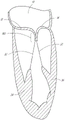
Referring to fig. 1A-1D, four chambers of the heart are shown, the left atrium 10, the right atrium 20, the left ventricle 30, and the right ventricle 40. The mitral valve 60 is disposed between the left atrium 10 and the left ventricle 30. Also shown are tricuspid valve 50 (which separates right atrium 20 from right ventricle 40), aortic valve 80, and pulmonary valve 70. The mitral valve 60 is composed of two leaflets (an anterior leaflet 12 and a posterior leaflet 14). In a healthy heart, the two leaflets are juxtaposed at the coaptation zone 16 during systole.
The fibrous annulus 120, which is part of the heart frame, provides attachment for the two leaflets of the mitral valve, referred to as the anterior leaflet 12 and the posterior leaflet 14. The leaflets are axially supported by attachment to chordae tendineae 32. The cord is in turn attached to one or both of the papillary muscles 34, 36 of the left ventricle. In a healthy heart, the cable support structure tethers the mitral valve leaflets, allowing the leaflets to open easily during diastole, but tolerates the high pressures that develop during ventricular systole. In addition to the tethering effect of the support structure, the shape and tissue consistency of the leaflets help promote effective sealing or coaptation. The leading edges of the anterior and posterior leaflets meet along a funnel-shaped coaptation zone 16, wherein a cross-section 160 of a three-dimensional Coaptation Zone (CZ) is schematically shown in fig. 1E.
The anterior and posterior mitral valve leaflets have different shapes. The anterior leaflet is more firmly attached to the annulus overlying the central fibrous body (the heart frame) and is somewhat stiffer than the posterior leaflet, which is attached to the more mobile posterior mitral annulus. About 80% of the occlusion area is the anterior leaflet. Adjacent to the commissures 110, 114, left (lateral) 124 and right (septal) 126 fibrous trigones formed where the mitral annulus merges with the base of the non-coronary cusp (non-coronary cusp) of the aorta are located on or in front of the annulus 120 (fig. 1F). The fibrous trigones 124, 126 form spaced extensions and lateral extensions of the central fibrous body 128. In some embodiments, the fibrous trigones 124, 126 may have advantages, such as providing a secure area for stable engagement with one or more annulus anchors (anchors) or atrial anchors. The coaptation region CL between the leaflets 12, 14 is not a simple line, but a curved, funnel-shaped surface interface. The commissures of the first 110 (lateral or left) and second 114 (septal or right) leaflets are where the anterior leaflet 12 meets the posterior leaflet 14 at the annulus 120. As best seen in the axial views of the atrium of fig. 1C, 1D and 1F, the axial cross-section of the coaptation region generally shows a curved line CL that is separated from the centroid of the annulus CA and from the opening through the valve during diastole CO. Furthermore, the leaflet edges have rounded teeth, especially in the posterior leaflet compared to the anterior leaflet. Poor coaptation may occur between one or more of these a-P (anterior-posterior) segment pairs a1/P1, a2/P2, and A3/P3, such that poor coaptation characteristics may vary along the curve of the coaptation region CL.
Referring now to fig. 2A, the properly functioning mitral valve 60 of the heart is open during diastole to allow blood to flow along the flow path FP from the left atrium to the left ventricle 30 and thereby fill the left ventricle. As shown in fig. 2B, with the ventricular pressure raised, first passively then actively, the functioning mitral valve 60 closes during systole and effectively separates the left ventricle 30 from the left atrium 10, thereby allowing the heart tissue surrounding the left ventricle to contract to push blood through the vascular system.
Referring to fig. 3A-3B and 4A-4B, there are several conditions or disease states in which the leaflet edges of the mitral valve are not sufficiently apposed and thus allow blood to flow from the ventricles back into the atria during systole. Regardless of the specific etiology of a particular patient, the failure of the leaflets to seal during ventricular systole is referred to as poor coaptation and causes mitral regurgitation.
In general, poor coaptation can result from over-tethering of the support structure of one or both leaflets, or can result from over-stretching or tearing of the support structure. Other less common causes include heart valve infections, congenital abnormalities, and trauma. Valve dysfunction can be caused by: the chordae tendineae are stretched (known as mitral valve prolapse), and in some cases, tears of the chordae tendineae 215 or papillary muscles (known as flail leaflets 220), as shown in fig. 3A. Alternatively, if the leaflet tissue itself is redundant, the valve may prolapse such that the height of coaptation occurs higher into the atrium, opening the valve higher in the atrium during ventricular systole 230. Any of the leaflets may prolapse or become flail. This condition is sometimes referred to as degenerative mitral regurgitation.
In over-tethering as shown in fig. 3B, the leaflets of a properly configured valve may not function properly due to annular enlargement or shape change (so-called annular enlargement 240). This functional mitral regurgitation is usually caused by myocardial failure and concomitant ventricular enlargement. And excessive volume loading caused by functional mitral regurgitation may itself exacerbate heart failure, ventricular and annular enlargement, and thus worsen mitral regurgitation.
Fig. 4A-4B illustrate the regurgitation BF of blood during the systolic phase in functional mitral regurgitation (fig. 4A) and degenerative mitral regurgitation (fig. 4B). The increased size of the annulus in fig. 4A, coupled with increased tethering due to hypertrophy of the ventricle 320 and papillary muscles 330, prevents the anterior leaflet 312 and posterior leaflet 314 from apposition, thereby preventing coaptation. In fig. 4B, the tearing of the chordae tendineae 215 causes the posterior leaflet 344 to prolapse upward into the left atrium, which prevents apposition with the anterior leaflet 342. In either case, the result is regurgitation of blood into the atrium, which reduces the effectiveness of left ventricular compression.
Additional descriptions of coaptation assistance devices, tools, anchors, features, systems, and methods that can be utilized in conjunction with the disclosure herein can be found in the following applications, each of which is incorporated by reference in its entirety: U.S. patent application No. 13/099532, filed 5/3/2011; U.S. patent application No. 13/531407, filed on 6/22/2012; U.S. patent application No. 14/313975, filed 6/24/2014; U.S. patent application No. 14/742199, filed on 6/17/2015; U.S. patent application No. 14/749344, filed on 24/6/2015; and U.S. patent application No. 10/419706, filed on month 4/18/2003.
In some embodiments, the coaptation assistance devices described herein can be deployed to cover the posterior leaflets, chordae tendinae, and papillary muscles. In some embodiments, the coaptation assistance device is attached superiorly to the posterior aspect of the annulus and inferiorly to the posterior aspect of the left ventricle via the annulus anchor and/or the ventricle anchor. In other embodiments, more than one annulus anchor and/or more than one ventricular anchor may be used to attach the coaptation assistance device. In some devices, one or more annulus anchors may be replaced by or supplemented with one or more atrial or commissure anchors, which in some embodiments may be annular. The coaptation assistance device can be attached to the superior surface of the posterior annulus, the posterior atrial wall, or the annulus itself. A coaptation zone has been established between the coaptation assistance device and the native anterior leaflet. Similar coaptation assistance devices can be used for both functional and degenerative mitral regurgitation, as failure of leaflet coaptation occurs in both regardless of the mechanism behind the dysfunction. In some embodiments, different sized coaptation assistance devices can be placed such that the native anterior leaflet opposes the coaptation device at a properly established coaptation point, blocking blood flow during ventricular systole.
By varying the size configured for a variety of anatomies, a variety of sizes of coaptation assistance devices can be provided. For example, there may be a height measured from an upper annulus attachment site to a lowermost edge of the coaptation assistance device in a plane substantially perpendicular to a plane defined by an annulus of the valve, a depth between the commissure points and the upper attachment site, and a bulge between a posterior wall of the commissure point height and the commissure points. There is also an inner and outer diameter of the coaptation assistance device, typically larger in the functional MR. During diastole, the coaptation assistance device can stay in substantially the same position while movement of the native anterior leaflet opens the valve, allowing blood to flow from the left atrium to the left ventricle with minimal restriction. In some embodiments, the surface of the coaptation assistance device can balloon or stretch upward during ventricular systole while the anchor remains stationary. This may be advantageous because the seal between the anterior or coaptation surface of the device and the native leaflets at the coaptation region during systole is enhanced. During diastole, the surface may return to the initial position toward the anterior leaflet where it was earlier. This may provide an improved blood flow path between the atrium and ventricle during diastole, thereby improving outflow from the atrium through the coaptation assistance device.
In some methods of use, the native posterior leaflet is left in place and the coaptation assistance device is attached superiorly to the posterior annulus or adjacent atrial wall. The various possible alternative embodiments may have different attachment mechanisms. In other methods of use, the posterior leaflet is not present, has been surgically removed, or is removed due to disease. In some methods of use, the native leaflets are attached to the posterior surface of the coaptation assistance device. In some methods of use, the coaptation assistance device can be attached to the anterior surface of the posterior leaflet, rather than the annulus or atrial wall. These are some examples of variations, but others are still contemplated. In some methods of use, an anchoring structure (not shown) may be advanced through the atrial wall into the coronary sinus from the coaptation assistance device, wherein the anchoring structure is attached to a mating structure in the coronary sinus. In some methods of use, an anchoring structure, which may be a mechanical structure or simple suture, may be passed through the atrial wall and anchored to the epicardial surface of the heart by a knot or mechanical unit such as a clip. Similarly, the inferior attachment may reach the ventricular muscle, access the epicardium or pericardium through the apex of the heart, and be secured from the outside or at other attachment sites using alternative attachment means.
The coaptation assistance devices described herein can exhibit a variety of desirable characteristics. Some embodiments do not necessarily rely on reshaping of the mitral annulus (e.g., by heat-shrinking of the annulus tissue, implantation of an annular ring prosthesis, and/or placement of a grasping mechanism above or below the valve plane or in the coronary sinus or associated vessel). Advantageously, they also do not have to disrupt the leaflet structure or rely on locking or fusion of the mitral leaflets together. Various embodiments may avoid reliance on ventricular reshaping and exhibit passive-type implant devices with limited deflection after implantation, which may result in very long fatigue life. Thus, the coaptation assistance device can be secured through the posterior leaflet while otherwise anatomically completing the native heart (e.g., ventricular, mitral annulus, etc.).
Regardless of which leaflet portion or portions exhibit poor coaptation, mitigation of the poor coaptation of the mitral valve can be effective. The treatments described herein will utilize a coaptation assistance device that is repositionable during the procedure and is removable even after full deployment and/or tissue response begins or completes, typically without damaging the valve structure. Nonetheless, the coaptation assistance devices described herein can be combined with one or more therapies that do rely on one or more of the above-mentioned excluded attributes. The coaptation assistance device can exhibit benign tissue healing and rapid endothelialization that inhibits migration, thromboembolism, infection, and/or erosion. In some cases, the coaptation assistance device will not exhibit endothelialization, but its surface will remain inert, which can also inhibit migration, thromboembolism, infection, and/or erosion.
Fig. 5A-5B show two views of one embodiment of a coaptation assistance device 500. The coaptation assistance device 500 can include a first surface 505 that can be disposed toward an inferior coaptation native leaflet (in the case of a mitral valve, the posterior leaflet), and a second surface 515 that can be disposed toward the anterior leaflet. The second surface 515 may include a apposition surface 560. The upper edge 540 of the coaptation assistance device 500 can be curved to fit the general shape of the annulus or adjacent atrial wall, as described herein. The upper edge 540 may curve downward toward the posterior leaflet, as shown in fig. 5A, or upward toward the atrial wall to match the general shape of the left atrial wall, as shown in fig. 6 and described herein.
The coaptation assistance device 500 can have a geometry that allows it to transect the valve between attachment sites in the atrium and ventricle. In some embodiments, the attachment site is in the atrium only. In some embodiments, the attachment site is only near the annulus and commissures of the valve. The coaptation assistance device 500 can be unattached near the lower edge 580. The coaptation assistance device 500 does not require ventricular attachment. In some embodiments, the geometry of the coaptation assistance device 500 helps to maintain the position of the coaptation assistance device 500 within the valve. In some embodiments, the coaptation assistance device 500 bends to cup the posterior leaflet. In some embodiments, the coaptation assistance device 500 curves back toward the upper edge 540. The coaptation assistance device 500 can provide a coaptation surface 560 for coaptation of the anterior leaflet. Fig. 5A and 5B illustrate this geometry.
In some methods of use, the posterior leaflet may remain intact. The coaptation assistance device 500 can be attached to the atrium or annulus such that it effectively occludes the posterior leaflet. In some methods of use, the posterior leaflet may be removed. In the case where the posterior leaflet is removed or has been removed, the coaptation assistance device 500 can replace the posterior leaflet. In some embodiments, the coaptation assistance device 500 only requires annulus attachment. In some embodiments, the coaptation assistance device 500 only requires attachment at a single point. The single point may be a central location of the coaptation assistance device 500, e.g., a centrally located bushing. In some embodiments, the coaptation assistance device 500 can be attached to the atrium or annulus along the edges. In some embodiments, the coaptation assistance device 500 can be attached to the atrium or annulus at a location spaced from the edges of the coaptation assistance device 500, for example, at a centrally located hub.
The coaptation assistance device 500 can include an annular sleeve 520 that engages the annulus anchor 800. The annulus anchor 800 may be engaged proximally by a driver as described herein. The annulus anchor 800 may include a sharp tip to engage tissue. In some methods of use, the tip of the annulus anchor 800 is within the annular liner 520 during delivery of the coaptation assistance device 500. In some methods of use, the tip of the annulus anchor 800 is above the ring portion 510 during delivery. The tip of the annulus anchor 800 may remain recessed within the annular bushing 520 until the annulus anchor 800 is rotated to engage tissue. In some embodiments, the coaptation assistance device 500 can be assembled in vitro, engaging the annulus anchor 800 with the coaptation assistance device 500 via the annular bushing 520 and engaging the driver with the annulus anchor 800. The driver may then be retracted into the delivery catheter with the coaptation assistance device 500 in the collapsed position. The drivers may be individually manipulated by the operator to place the annulus anchor 800 in position. Alternatively, the annulus anchor 800 may be sequentially engaged with the coaptation assistance device 500 and/or the driver before or after deployment through the delivery catheter. The coaptation assistance device 500 after placement can completely cover the posterior leaflet such that the coaptation assistance device 500 coapts with the anterior leaflet during systole and maintains a valve seal at the annulus ring with the native anterior leaflet.
In some embodiments, the annulus anchor 800 is an active anchor. The user can selectively engage and disengage the annulus anchor 800 from the tissue. Unlike barbs or other passive-type anchors, the annulus anchor 800 must be activated to engage tissue, for example, by rotation. The annulus anchor 800 allows for placement of the coaptation assistance device 500 prior to engagement of the annulus anchor 800. The coaptation assistance device 500 can be in contact with tissue without any attachment of the annulus anchor 800. In some embodiments, the annulus anchor 800 and corresponding bushing 520 are centrally located on the coaptation assistance device 500. The annulus anchor 800 and corresponding bushing 520 are spaced from any edge of the coaptation assistance device 500. The annulus anchor 800 and corresponding bushing 520 may be centrally located to prevent wobble of the coaptation assistance device 500 when the coaptation assistance device 500 is supported by the annular bushing 520. Corresponding bushings 520 provide advantageous locations to support and move the coaptation assistance device 500.
The annular bushing 520 may have an annulus anchor 800 built-in or coupled thereto. In some embodiments, the annulus anchor 800 may be retained within the annular bushing 520 by a latch as described herein. A pin may be passed through the helical structure of the annulus anchor 800 to prevent the annulus anchor 800 from being removed from the annular bushing 520 by blunt force. The annulus anchor 800 may include a helical structure that is rotatable relative to the annular bushing 520. In some embodiments, other anchors may be used. The annulus anchor 800 may be in the form of a cord or other attachment unit that extends from the coaptation assistance device 500 across the ventricular septum to the right ventricle. The annulus anchor 800 may be in the form of a cord or other attachment unit that extends through the apex of the heart into the epicardium or pericardium. The annulus anchor 800 may be secured from outside the heart in a combined epicardial/endocardial procedure. When helical anchors are used, they may comprise a biologically inert material, such as platinum/Ir, nitinol, and/or stainless steel.
In some embodiments, the coaptation assistance device 500 can include a single central annulus anchor 800 inside the annular liner 520. The coaptation assistance device 500 can be delivered percutaneously through attachment of a delivery catheter to the annular liner 520 as described herein. The coaptation assistance device 500 can be configured to be adjustably disposed by removing and reattaching the annulus anchor 800. The coaptation assistance device 500 can be recaptured by removal of the annulus anchor 800 and retraction of the coaptation assistance device 500. The coaptation assistance device 500 can also include secondary anchors, including commissure anchors, ventricular anchors, annulus anchors, barbs, cables, or any other known fixation device.
As can be seen in fig. 5A-5B, the coaptation assistance device 500 can include a plurality of struts 530. In some embodiments, one or more of the struts 530 have one end terminating at the bushing 520 and another end extending radially outward toward one of the upper edge 540, the side edges 570 and 575, and the lower edge 580 of the coaptation assistance device 500. The struts 530 may extend outward from the bushing 520 in various directions, and may be spaced apart from adjacent struts 530 at regular or irregular intervals. In some embodiments, adjacent struts 530 extend outwardly from the liner at an angle of about 5 degrees to about 45 degrees, about 10 degrees to about 30 degrees, or about 5, 10, 15, 20, 25, or 30 degrees relative to adjacent struts 530. The struts 530 may be arranged generally parallel to the longitudinal axis of the coaptation assistance device 500 to help maintain the coaptation assistance device 500 shape when placed. The struts 530 may cause the coaptation assistance device 500 to assume a reduced configuration for deployment through a catheter. In some embodiments, the struts 530 forming a portion of the apposition zone of the implant 500 have a greater maximum length than the struts 530 forming only a portion of the annular zone of the implant. In some embodiments, the struts 530 forming a portion of the apposition zone of the implant may be at least about 10%, 20%, 30%, 40%, 50%, 75%, 100%, 125%, or 150% longer than the struts 530 forming a portion of the annular zone of the implant, for example.
Fig. 5A shows a view of the coaptation assistance device 500 with the annulus anchor site 535. The annulus anchor 535 may be part of the strut 530. The annulus anchor site 535 is shown extending downward from the coaptation assistance device 500 in fig. 5A. In other embodiments, the annulus anchor site 535 may extend from the coaptation assistance device 500 in other directions to engage tissue. In some embodiments, the annulus anchor site 535 comprises one or more barbs with sharp tips. The annulus anchoring site 535 may be a passive anchor.
In some embodiments, the coaptation assistance device 500 can include one or more retractable barbs. For example, the barbs may be retracted during delivery of the coaptation assistance device 500. For example, the barbs may be advanced after the coaptation assistance device 500 is disposed relative to the anatomy. In some embodiments, the barbs are actively retracted and/or advanced. For example, the delivery catheter described herein may include a mechanism coupled with the barb that is designed to retract and/or advance the barb. In other embodiments, the barbs are passively advanced and/or retracted. In some embodiments, the coaptation assistance device 500 is delivered with the barbs in a retracted state. In some embodiments, the barbs may be covered by a valve body cover as described herein. In some embodiments, the interface between the tissue and the valve body covering pushes the valve body covering back and exposes the barbs. In some embodiments, the tissue lyses and/or absorbs a portion of the valve body covering and exposes the barbs. In some embodiments, movement of the purse string-type suture described herein advances the barbs. In some embodiments, movement of the purse string-type suture causes movement of the valve body covering to expose the barbs. Other configurations are contemplated.
The annular anchoring site 535 may define a diameter D1 shown in fig. 5B, which may correspond to the distance between the inner and outer commissures or the intra-commissure distance (ICD) of the native valve in some embodiments. D1 may be 20-60mm, and in some embodiments, preferably 35-45mm in length, which most closely corresponds to the widest range of human mitral ICDs. In some embodiments, D1 may be the distance from the right fiber triangle to the left fiber triangle.
The coaptation assistance device 500 can include a generally annular portion 510. When deploying the coaptation assistance device 500, the annular portion 510 can be disposed over the native leaflets. In some embodiments, the ring portion 510 may curve toward the annulus or away from the annulus. The annular portion 510 may be concave. In other embodiments, the ring portion 510 may be substantially flat relative to the annulus. One or more of the struts 530 may curve laterally from the bushing 520 toward the upper edge 540 to help maintain the shape of the annular portion 510 of the coaptation assistance device 500 when deployed. The coaptation assistance device 500 can be bent downward from the hub 520 toward the annulus anchor 535. In some embodiments, the coaptation assistance device 500 is not against the posterior leaflet. In some embodiments, the annulus anchor site 535 is the only point of contact between the posterior annulus of the mitral valve and the coaptation assistance device 500. The upper edge 540 may include a circular radius of curvature. The annular radius of curvature may be curved toward the annulus. The annular radius of curvature may be curved toward the apposition surface 560. In some embodiments, the radius of curvature of the loop can be 0mm to 5mm, 5mm to 10mm, 10mm to 15mm, 15mm to 20mm, 20mm to 25mm, 25mm to 30mm, and the like.
The struts 530 may be constructed of a radiopaque material. In some embodiments, the struts 530 are constructed of an elastically deformable material such as a shape memory metal, e.g., nitinol, or a shape memory polymer. In some embodiments, the material is Elgiloy. In other embodiments, the struts 530 may be constructed of other materials, including stainless steel, polypropylene, high density Polyethylene (PE), dacron, acellular collagen matrices such as SIS, or other plastics, among others. In other embodiments, the struts 530 may be a combination, such as a high density PE sheath surrounding a core of ePTFE, dacron, and/or polypropylene. The struts 530 may have a circular cross-section, an oval cross-section, or a ribbon shape. In some embodiments, the struts 530 are coil springs or zigzag shaped. The strut 430 may have a constant stiffness. In some embodiments, one or more struts 530 can have a different stiffness along the length of the one or more struts 530. The struts 530 may be stiffer at the end of the annulus than at the end of the ventricle of the coaptation assistance device 500. The struts 530 may be less stiff at the end of the annulus than at the end of the ventricle of the coaptation assistance device 500. The strut 530 may be stiffer at a midpoint, such as at an inflection point or curve. The strut 530, along with one or more other support structures, may form a frame. In some embodiments, one or more support structures may be provided that extend parallel to the upper edge 540 of the coaptation assistance device 500 and help maintain the shape of the upper edge 540. In some embodiments, struts 530 and/or other support structures of the frame may be laser cut from a nitinol tube.
The coaptation assistance device body covering 550 can be constructed of a material such as ePTFE. Other materials for the coaptation assistance device body covering 550 include polyester, polyurethane foam, polycarbonate foam, biological tissue (e.g., porcine pericardium, processed bovine pericardium, pleura, peritoneum), silicone, dacron, acellular collagen matrices, and the like. In some embodiments, the coaptation assistance device body covering 550 can include a foam material surrounded by ePTFE. In some embodiments, the use of a sponge or foam material enhances the ability to fold the coaptation assistance device 500 to a diameter small enough to pass through a catheter. In some embodiments, the coaptation assistance device body cover 550 is free of holes. In other embodiments, the coaptation assistance device body cover 550 can have micropores to enhance endothelialization and cell attachment. The coaptation assistance device body covering 550 can also contain radiopaque materials or echogenic enhancing materials for better visualization. Any support structure of the coaptation assistance device 500, including the struts 530 or the support interface including the bushings 520, can be coated with a radiopaque material, such as gold or platinum, or impregnated with barium. The apposition surface 560 may be coated with an echogenic enhancing material. The coaptation assistance device body covering 550 can be coated with a material that inhibits thrombosis, such as heparin-bonded compounds or quinoline and quinoxaline compounds, or with a material that accelerates endothelialization, or with an antibiotic that inhibits infection. In some embodiments, purse string-type sutures 1010 described herein may include radiopaque materials or echogenic materials for better visualization.
In some embodiments, the struts 530 may be sandwiched between layers of the coaptation assistance device body cover 550. The coaptation assistance device body cover 550 can be composed of the same material on the first surface 505 and the second surface 515. The coaptation assistance device body cover 550 can be constructed of different materials on the first surface 505 or a portion thereof and the second surface 515 or a portion thereof. In some embodiments, the struts 530 may be attached to or embedded in the first surface 505 or the second surface 515 of a single layer of the coaptation assistance device body cover 550. In some embodiments, the struts 530 may be "stitched" through the coaptation assistance device body covering 550. The annulus anchor site 535 may be the exposed end of the strut 530 from the coaptation assistance device body cover 550.
The coaptation assistance device 500 can include cinch cord type sutures 1010. A cinch cord type suture 1010 may extend along a portion of the coaptation assistance device 500. A purse string type suture 1010 may extend along the upper edge 540 or a portion thereof. A purse string type suture 1010 may extend along the side edge 570 or a portion thereof. A purse string type suture 1010 may extend along the side edge 575 or a portion thereof. A cinch cord type suture 1010 may extend along or a portion of the lower edge 580. A cinch cord type suture 1010 may extend along the perimeter of or a portion of the coaptation assistance device 500. Cinch cord type stitches 1010 may extend along one or more of the struts 530. The cinch cord type suture 1010 may extend in a straight path, a non-straight path, a curve, a semi-circle, or any open or closed shape.
In some embodiments, the cinch cord type suture 1010 may be sandwiched between layers of the valve body covering 550. For example, cinch cord type sutures 1010 may be disposed in the cavity between layers of the coaptation assist device body covering 550. In some embodiments, the cinch cord type sutures 1010 may be attached to or embedded in the single layer first surface 505 or second surface 515 of the valve body covering 550. In some embodiments, purse string-type sutures 1010 may be "sewn" through the coaptation assistance device body covering 550. A purse string type suture 1010 may be threaded through the first surface 505 to the second surface 515 and back to the first surface 505. Cinch cord type sutures 1010 may include one or more exposed ends from the coaptation assist device body covering 550. In embodiments where the cinch cord suture 1010 is a loop, the cinch cord suture may include one or more exposed portions of the loop from the valve body covering.
The coaptation assistance device 500 can be folded by tightening the cinch cord type suture 1010 at the mouth of the purse. The coaptation assistance device 500 can be deployed by loosening the cinch cord type suture 1010 at the mouth of the purse. One or more exposed ends or loops may be manipulated through a delivery catheter or other tool to tighten or loosen the purse string-type suture 1010. The ability to fold or unfold the coaptation assistance device 500 can facilitate recapture of the coaptation assistance device 500 and/or rearrangement of the coaptation assistance device 500.
The coaptation assistance device 500 can be rotated by tightening one or more cinch cord type sutures 1010 and/or loosening one or more cinch cord type sutures 1010. For example, tightening one or more cinch cord type sutures 1010 on the side edge 570 and/or loosening one or more cinch cord type sutures 1010 on the side edge 575 may rotate the coaptation assistance device 500. One or more cinch cord type sutures 1010 may be coupled to the coaptation assistance device 500 to enable multi-directional rotation.
The coaptation assistance device 500 can be deployed by loosening the cinch cord type suture 1010 at the mouth of the purse. One or more exposed ends or loops may be manipulated through a delivery catheter or other tool to tighten or loosen the purse string-type suture 1010. The ability to fold or unfold the coaptation assistance device 500 can facilitate recapture of the coaptation assistance device 500 and/or rearrangement of the coaptation assistance device 500.
The apposition surface 560 of the apposition aid 500 may be adjusted by movement of the cinch cord type suture 1010 through the cinch pocket. One or more exposed ends or loops may be manipulated by a delivery catheter or other tool to tighten or loosen the purse string-type sutures 1010 to change the curvature of the apposing surface 560 in situ. The ability to adjust the curvature of the coaptation assistance device 500 can facilitate conforming to the geometry of the heart, including the geometry of the anterior leaflet.
The loop size of the coaptation assistance device 500 can be adjusted by movement of the cinch cord type suture 1010 through the cinch slot. One or more exposed ends or loops may be manipulated through a delivery catheter or other tool to tighten or loosen the cinch cord type sutures 1010 to change one or more dimensions of the coaptation assistance device 500 in situ. The ability to adjust the size of the coaptation assistance device 500 can be advantageous to conform to the geometry of the heart.
The coaptation assistance device 500 can include one or more cinch cord type sutures 1010. In some embodiments, the coaptation assistance device 500 includes one purse bag opening drawstring type stitch, two purse bag opening drawstring type stitches, three purse bag opening drawstring type stitches, four purse bag opening drawstring type stitches, five purse bag opening drawstring type stitches, six purse bag opening drawstring type stitches, seven purse bag opening drawstring type stitches, eight purse bag opening drawstring type stitches, nine purse bag opening drawstring type stitches, ten purse bag opening drawstring type stitches, and so forth. For example, purse string-type sutures 1010 may extend along each edge of the coaptation assistance device 500. When multiple cinch cord type sutures are provided, the cinch cord type sutures 1010 may be used together to change the configuration of the coaptation assistance device 500. When multiple cinch cord type sutures are provided, the cinch cord type sutures 1010 may be used independently to change the configuration of the coaptation assistance device 500.
Fig. 5A further illustrates the coaptation device height, which corresponds to the distance between the lower edge 580 and the annular liner 520 measured perpendicular to a plane defined by the annulus of the valve. The apposition device height of some embodiments may be 10-80mm, and some embodiments 40-55 mm. The height of the involution device can be 10-20mm, 20-30mm, 30-40mm, 40-50mm, 50-60mm, 60-70mm, 70-80mm and the like.
Fig. 5A illustrates a generally triangular shape of the coaptation assistance device 500, such that the coaptation assistance device 500 has an upper edge 540, side edges 570 and 575, and a lower edge 580. In some embodiments, the upper edge 540 has a length that is greater than the length of the lower edge 580, such that the lateral distance between the side edges 570 and 575 generally decreases from an upper portion to a lower portion on the coaptation assistance device 500. For example, the length of upper edge 540 may be in the range of 15-50mm or 25-35mm, while the length of lower edge 580 may be in the range of 1-15mm or 2-6 mm.
The annular bushing 520 may be a bushing, an eyelet, or any other tethering point known in the art. In some embodiments, the annular bushing 520 is located at the midpoint of the distance D1. In some embodiments, the annular bushing 520 is centered in the middle to prevent wobble of the coaptation assistance device 500 when the coaptation assistance device 500 is supported by the annular bushing 520. In other embodiments, the annular bushing 520 is located at one of the commissures. Although only one annulus anchor 800 is shown, in other embodiments, more than two annular bushings 520 may be provided.
In some embodiments, the struts 530 may comprise NiTi tubes. In some embodiments, the struts 530 may be laser cut from the tube. In some embodiments, a frame including one or more struts 530 and/or one or more support structures may be laser cut from a single sheet of material. In some embodiments, the frame including one or more struts 530, annular bushing 520, and/or one or more support structures may be integrally formed. In some embodiments, the coaptation assistance device body covering 550 comprises an ePTFE laminate. The laminate can surround one or more of the struts 530 and/or one or more support structures (e.g., one side, two sides, first side 505, second side 515). The strut 530 and/or one or more support structures may be enclosed by more than two laminate layers. The periphery of the annular portion 510 of the coaptation assistance device 500 can be cupped down. The periphery of the annular portion 510 of the coaptation assistance device 500 can be cupped up. The perimeter of the annular portion 510 of the coaptation assistance device 500 can include a secondary anchor, such as an annular anchoring site 535.
In some embodiments, the annular anchor 800 and the annular liner 520 form a single central anchoring system. In some embodiments, the coaptation assistance device 500 is secured to tissue with only one annulus anchor 800 passing through the sleeve 520. In other embodiments, additional fixation is included. In some embodiments, the coaptation assistance device 500 is secured to tissue by the one annulus anchor 800 passing through the sleeve 520 and the annulus anchor site 535 as described herein. The system may include features that allow rotational adjustment of the coaptation assistance device 500. For example, the hub 520 and/or the annulus anchor 800 may be coupled to a delivery catheter to allow for axial movement and/or torque transfer. The coaptation assistance device 500 can be held stationary by the delivery catheter such that rotation of a feature of the delivery catheter, such as a handle, causes rotation of the coaptation assistance device 500. The coaptation assistance device 500 can be held stationary by the delivery catheter such that axial movement of a feature of the delivery catheter, such as a drive shaft, causes axial movement of the coaptation assistance device 500.
In some embodiments, the bushing 520 is located at an intermediate position on the coaptation assistance device 500. The intermediate position may be a central position on the ring portion 510. The intermediate position may be between the side edges 505, 515. An intermediate position may be between the upper edge 540 and the apposing surface 560. The intermediate position may enhance the stability of the coaptation assistance device 500 when the coaptation assistance device 500 is grasped at a single location, such as at the hub 520 and/or the annulus anchor 800. The intermediate position may be aligned with the structure of the mitral valve. The intermediate positions may be aligned along the coaptation region.
In some embodiments, the coaptation assistance device 500 is delivered percutaneously as described herein. In some embodiments, the coaptation assistance device 500 is adjustable via a delivery catheter. For example, the coaptation assistance device 500 can be deployed and/or folded through a delivery catheter. For example, the coaptation assistance device 500 can rotate about a fixed position of the annular bushing 520. For example, the coaptation assistance device 500 can be recapturable. For example, the coaptation assistance device 500 can be engaged and re-engaged by a delivery catheter. For example, the annulus anchor 800 may be disengaged from the tissue and the delivery catheter may recapture the coaptation assistance device 500.
Fig. 5C-5D illustrate embodiments of a frame 565 of the coaptation assistance device 500. These figures illustrate the flat pattern of the frame 565 prior to bending and/or shape fixation. In some embodiments, the frame 565 is cut from a tubular blank. In other embodiments, the frame 565 is cut from a flat blank, such as a flat sheet of material. The frame 565, including portions thereof, may be laser cut. The frame 565 may include one or more struts 530. In the embodiment shown in fig. 5D, the frame 565 includes twenty struts 530, although other configurations are contemplated (e.g., one strut, two struts, three struts, four struts, five to ten struts, ten to fifteen struts, fifteen to twenty struts, twenty to twenty-five struts, twenty-five to thirty struts, etc.).
In some embodiments, one or more pillars 530 are coupled to the backing 585. In some embodiments, the backing 585 is transverse to the direction of the pillars 530. In the illustrated embodiment, the backing 585 is vertical or substantially vertical and the posts 530 are horizontal or substantially horizontal. In some embodiments, the backing 585 is an annular liner 520. For example, the two ends of the backing 585 may be joined using methods known in the art to form the annular liner 520. For example, if the frame 565 is cut from a flat blank, the two ends are connected. In other embodiments, the frame 565 is formed from a tubular blank. The backing 585 may be a portion of an uncut tubular blank. If the frame 565 is formed from a tubular blank, it may not be necessary to attach the two ends of the backing 585. The uncut tubular blank may form an annular bushing 520. A pattern (patters) of frames 565 as shown in fig. 5D may be cut from the tubular blank, thereby eliminating the need to attach both ends of the backing. Other modes of manufacture are contemplated to form frame 565. In other embodiments, backing 585 forms at least a portion of annular liner 520. In some embodiments, backing 585 surrounds at least a portion of annular liner 520. In some manufacturing methods, the backing 585 may be formed in a circular shape. In some manufacturing methods, once the backing 585 is formed into a circular shape, the pillars 530 extend radially outward from the backing 585. Backing 585 may include one or more openings designed to receive pins, as disclosed herein. In some manufacturing methods, the backing 585 is removed.
Referring to fig. 5A and 5C, a plurality of struts 530 may extend from the annular bushing 520 to a lower end 580. In some embodiments, the struts 530 are longer than the other struts 530 of the frame 565. In some embodiments, struts 530 may include anchors or barbs that interact with the subvalvular structure (including the ventricular wall). In some embodiments, the struts engage the posterior leaflet or other anatomical structure. In some embodiments, ventricular anchoring is passive.
Referring to fig. 5A-5D, a plurality of struts 530 may extend from the annular liner 520 to an upper end 540. In some embodiments, the struts 530 are shorter than the other struts 530 of the frame 565. In some embodiments, these struts 530 form an atrial anchor and/or an annulus anchoring site 535 as described herein. In some embodiments, the struts engage the annulus or other anatomical structure. In some embodiments, the annulus anchoring is passive.
Referring to fig. 5A and 5D, a plurality of struts 530 may extend from the annular liner 520 to the side edges 570 and 575. In some embodiments, these struts 530 have an intermediate length between the ventricular struts and the atrial struts. In some embodiments, the struts engage the commissures or other anatomical structures. In some embodiments, the commissure anchors are passive.
The struts 530 may have a variety of lengths based on the desired shape of the coaptation assistance device 500. As shown in fig. 5C-5D, more than two struts 530 have different lengths. As shown in fig. 5C-5D, more than two struts 530 have the same length. Fig. 5C shows a schematic pattern of the frame 565. One or more of the upper three struts may form the apposition surface 560 and extend to the lower edge. One or more of the lower three struts may form a loop and extend to the upper edge. The struts 530 may be laser cut from the tube. The length may be measured from the annular bushing 520 to the edge of the coaptation assistance device 500. The strut length may range from 1mm to 50 mm. For the ring portion 510, the strut length may range from 5mm to 35 mm. For the ring portion 510, the strut length may be about 15 mm. For the apposition surface 560, the strut length may range from 20mm to 35 mm. For the apposition surface 560, the strut length may be about 30 mm. Other configurations of ranges of strut lengths are contemplated, such as 5mm to 45mm, 10mm to 40mm, 15mm to 35mm, about 5mm, about 10mm, about 15mm, about 20mm, about 25mm, about 30mm, about 35mm, about 40mm, about 45mm, about 50mm, about 55mm, about 60mm, 1mm to 10mm, 5mm to 15mm, 10mm to 20mm, 15mm to 25mm, 20mm to 30mm, 25mm to 35mm, 30mm to 40mm, and so forth.
The width may be measured perpendicular to the length of the strut. The strut width may range from 0.1mm to 2 mm. One or more struts can have an outer diameter or width of about 0.1mm, 0.2mm, 0.3mm, 0.4mm, 0.5mm, 0.6mm, 0.7mm, 0.8mm, 0.9mm, 1mm, 1.1mm, 1.2mm, 1.3mm, 1.4mm, 1.5mm, 1.6mm, 1.7mm, 1.8mm, 1.9mm, 2mm, less than.5 mm, less than 1mm, less than 1.5mm, less than 2mm, and the like. One or more struts 530 can have varying widths along the strut length. In some embodiments, one or more struts 530 taper near the edge of the coaptation assistance device 500. In some embodiments, one or more struts 530 taper near the annular bushing 520. The one or more struts 530 may include a reduced diameter or taper at the connection between the one or more struts 530 and the annular liner 520. The taper near the annular bushing 520 may facilitate folding of the coaptation assistance device 500. The taper near the annular bushing 520 may facilitate insertion of the coaptation assistance device 500 into the delivery catheter. The tapering may reduce stress and/or strain in the strut 530 during folding. In some embodiments, tapering may contribute to longer fatigue life. In some embodiments, one or more struts 530 comprise a varying width taper. The width of the strut 530 may vary along the length of the strut 530. One or more struts 530 can include perforations along the length of the strut 530. In some embodiments, the perforations may reduce stress of the struts 530. In some embodiments, the eyelets can facilitate attachment between the struts 530 and the valve body covering 550.
The thickness can be measured perpendicular to the strut length and strut width. The thickness may be determined by the material thickness of the frame, as described herein. The strut thickness may range from 0.2mm to 0.5 mm. One or more of the struts may have a thickness of about 0.1mm, 0.2mm, 0.3mm, 0.4mm, 0.5mm, 0.6mm, 0.7mm, 0.8mm, 0.9mm, 1mm, 1.1mm, 1.2mm, 1.3mm, 1.4mm, 1.5mm, 1.6mm, 1.7mm, 1.8mm, 1.9mm, 2mm, less than.5 mm, less than 1mm, less than 1.5mm, less than 2mm, etc.
One or more of the struts 530 can include barbs. In some embodiments, the barbs may be configured for placement near the ventricular end of the coaptation assistance device 500. In some embodiments, the barbs may bend out of the plane of the strut 530. In some embodiments, the barbs may have a bayonet configuration. In some embodiments, the barbs may have sharp tips. In some embodiments, one or more struts 530 may be bifurcated. In some embodiments, one or more struts 530 may include one or more zig-zag portions. In some embodiments, the zig-zag portion reduces stress and/or increases flexibility of the strut 530. In some embodiments, the zig-zag portion facilitates attachment between the struts 530 and the coaptation assistance device body covering 550.
In some embodiments, one or more struts 530 can include supplemental barbs. In some embodiments, the supplemental barbs may be bent out of the plane of the struts 530. In some embodiments, one or more portions of the length of the strut are bent out of the surface of the strut. For example, a portion of the strut may twist or bend during manufacture. In some embodiments, the portion bent out of the plane is shaped to engage tissue. In some embodiments, one or more of the pillars 530 may include an increased width to compensate for electropolishing or other post-fabrication processes. In some embodiments, backing 585 may include one or more features for engaging a delivery catheter as described herein. In some embodiments, backing 585 may include one or more notches designed to connect with locking tabs or other features of a delivery catheter as described herein. In some embodiments, one or more struts 530 can comprise a greater width than other struts 530. In some embodiments, the frame 565 includes more than two struts 530 having a greater width than the other struts 530. Two or more struts 530 may facilitate visualization of the coaptation assistance device 500. In some embodiments, more than two struts 530 with larger widths are designed to be placed near the commissures when the coaptation assistance device 500 is deployed. In some embodiments, one or more struts 530 can have a smaller width than one or more other struts. In some embodiments, each strut 530 has the same width near the annular bushing 520. The backing 585 can be modified to interface with a delivery catheter, as described herein. The backing 585 can be designed to allow independent rotation of the anchor 800 within the liner of the coaptation assistance device 500.
Fig. 5E, 5F, and 5G illustrate an embodiment of the coaptation assistance device 500 without barbs. Fig. 5E shows a perspective view of the coaptation assistance device 500. Fig. 5F shows a perspective view of the first surface 505 disposed toward an inferior coaptation native leaflet. Fig. 5G shows a cross-sectional schematic view including anchor 800.
Fig. 5H, 5I, and 5J illustrate an embodiment of a coaptation assistance device 500 having a leaflet anchoring site 545. As shown in fig. 5A, the annulus anchor sites 535, such as barbs, may extend along the edges of the coaptation assistance device 500. Fig. 5H, 5I, and 5J illustrate one embodiment of a coaptation assistance device 500 having a leaflet anchor site 545 extending from a first surface 505 disposed toward an inferior coaptation native leaflet.
Fig. 5H illustrates a perspective view of the coaptation assistance device 500, including an enlarged portion showing the leaflet anchoring site 545. Fig. 5I shows a perspective view of a first surface 505 disposed toward an inferior coaptation native leaflet. Fig. 5J shows a cross-sectional schematic view including anchor 800.
In some embodiments, the leaflet anchor site 545 comprises one or more barbs having a sharp tip. The leaflet anchoring site 545 may be a passive anchor. In some embodiments, the coaptation assistance device 500 can include one or more retractable barbs. For example, the leaflet anchor site 545 may be retracted during delivery of the coaptation assistance device 500. For example, the leaflet anchor site 545 may be advanced after the coaptation assistance device 500 is disposed relative to the anatomy. In some embodiments, the leaflet anchor site 545 is actively retracted and/or advanced. For example, the delivery catheters described herein can include a mechanism coupled with the leaflet anchoring site 545 designed to retract and/or advance the barbs. In other embodiments, the leaflet anchor site 545 is passively advanced and/or retracted. In some embodiments, the leaflet anchor site 545 can be covered by a valve body covering as described herein. In some embodiments, the interface between the tissue and the valve body covering pushes the valve body covering back and exposes the leaflet anchor site 545. In some embodiments, the tissue lyses and/or absorbs a portion of the valve body covering and exposes the leaflet anchor site 545. In some embodiments, movement of the cinch-cord type sutures described herein advances the leaflet anchor site 545. In some embodiments, movement of the cinch-pocket cinching cord type suture causes movement of the valve body covering to expose the leaflet anchor site 545. Other configurations are contemplated.
One or more struts 530 can have one or more barbs along the length of the strut 530. In the illustrated embodiment, five struts 530 each have four leaflet anchoring sites 545 along the length of the struts. Other configurations are contemplated that vary the number of struts 530 (e.g., one strut, two struts, three struts, four struts, five struts, six struts, seven struts, eight struts, nine struts, ten struts, etc.) and vary the number of leaflet anchor sites 545/struts 530 (e.g., one barb, two barbs, three barbs, four barbs, five barbs, six barbs, seven barbs, eight barbs, nine barbs, ten barbs, etc.). One or more struts 530 can have the same number of leaflet anchor sites 545. More than two struts 530 can have different numbers of leaflet anchor sites 545. The leaflet anchor site 545 may be configured to engage the posterior leaflet.
In some embodiments, the struts 530 can be sandwiched between layers of the valve body covering 550. In some embodiments, the struts 530 may be attached to or embedded in the first surface 505 or the second surface 515 of a single layer of the valve body covering 550. In some embodiments, the struts 530 may be "sewn" through the valve body covering 550. The first surface 505 can include one or more openings for the leaflet anchor site 545. In other embodiments, the leaflet anchor site 545 may pass through the valve body covering 550. The leaflet anchoring site 545 may have a pre-set curve that may exert a force on the first surface 505. The leaflet anchor sites 545 may be sharpened to penetrate the valve body covering 550.
The frame 565 may have a number of advantages. The frame 565 may be formed of a flat pattern. The frame 565 may include an edge that forms the annular spacer 520. The edges may include longitudinal stripes or backings 585. One or more posts 530 may extend from the backing 585. In the illustrated embodiment of fig. 5C and 5D, one or more struts 530 are perpendicular to the longitudinal strips. The struts 530 are generally parallel. In some embodiments, the posts 530 are generally perpendicular to the backing 585 that forms the annular liner 520. In some embodiments, the pillars 530 form an angle with the backing 585. For example, the longitudinal axis of the strut 530 can form an acute angle with the backing 585. The angle facilitates folding of the struts 530 into the delivery catheter.
The frame 565 may be constructed from a single planar piece of material. The frame 565 may be precisely cut using water jets, laser etching, or similar techniques. Details of the post 530 including the barb may be machined into the post 530. The frame 565 may be bent and/or shaped to achieve a desired geometry. In some embodiments, the backing 585 is folded to form loops. The frame 565 may be rolled into a tube shape. The backing 585 may be welded or fastened. The backing 565 may be considered to be the annular spacer 520 when fastened end-to-end to form an annulus.
The struts 530 are bent into the desired configuration. The struts 530 may form one or more curves. The strut 530 may have one or more inflection points. The struts 530 may have concave portions and/or convex portions. One or more struts 530 may include a radially outward taper (flare) starting at the inflection point. In some embodiments, the upper edge 540 curves upward away from the lower edge 580. In some embodiments, the upper edge 540 is curved downward toward the lower edge 580. In some embodiments, one or more of the struts 530 can be substantially flat. The struts 530 near the commissures can be substantially flat. In some embodiments, the lower edge 580 curves back toward the upper edge 540. In some embodiments, the lower edge 580 curves forward away from the upper edge 540.
The struts 530 may be evenly spaced around the circumference of the annular bushing 520. The struts 530 may be unevenly spaced about the circumference of the annular liner 520. The struts 530 extending along a portion of the circumference of the annular liner 520 are different than the struts extending along another portion of the circumference of the annular liner 520. One or more designated portions of the strut 530 may be designed to be placed near the annulus region of the heart. One or more designated portions of struts 530 may be designed to be placed near the commissure regions of the heart. One or more designated portions of the struts 530 may be designed to be placed near a ventricular region of the heart. The geometry of the radially extending struts 530 may be shaped to fit the geometry of the patient. In some embodiments, the geometry is patient-specific. The operator may shape one or more struts 530 based on the geometry of the heart. The operator may change the shape of one or more struts 530 based on the geometry of the patient.
Fig. 5K illustrates the dimensions of the coaptation assistance device 500. The coaptation assistance device 500 can include a dimension a. Dimension a may be a linear protrusion dimension or a posterior protrusion. In some embodiments, dimension a may range from 1mm to 40 mm. In some embodiments, dimension a may range from 4mm to 24 mm. Other configurations of the range of dimension a are contemplated, such as 5mm to 35mm, 10mm to 30mm, 15mm to 25mm, about 1mm, about 2mm, about 3mm, about 4mm, about 5mm, about 6mm, about 7mm, about 8mm, about 9mm, about 10mm, 1mm to 10mm, 5mm to 15mm, 10mm to 20mm, 15mm to 25mm, 20mm to 30mm, 25mm to 35mm, 30mm to 40mm, and so forth. Dimension a may be 0mm if there is no posterior protrusion, for example, if the coaptation assistance device 500 is straight.
The coaptation assistance device 500 can include a dimension B. In some embodiments, dimension B may be a radius of curvature. The radius of curvature may be concave or convex, as described herein. In some embodiments, dimension B may range from 1/16 inches to 1/2 inches. In some embodiments, dimension B may range from 1.5mm to 13 mm. In some embodiments, dimension B may range from 1/4 inches to 3/8 inches. In some embodiments, dimension B may range from 6mm to 9.5 mm. In some embodiments, dimension B may range from 1mm to 15 mm. Other configurations of the range of dimension B are contemplated, such as 2mm to 14mm, 3mm to 13mm, 4mm to 12mm, 5mm to 11mm, 6mm to 10mm, 7mm to 9mm, about 1mm, about 2mm, about 3mm, about 4mm, about 5mm, about 6mm, about 7mm, about 8mm, about 9mm, about 10mm, 1mm to 10mm, 5mm to 15mm, 10mm to 20mm, and so forth. The dimension B may be 0mm if there is no curvature, for example if the coaptation assistance device 500 is straight.
The coaptation assistance device 500 can include a dimension C. In some embodiments, dimension C may be a radius of curvature near upper edge 540. In some embodiments, dimension C may range from 1mm to 10 mm. In some embodiments, dimension C may range from 1mm to 5 mm. Other configurations of the range of dimension C are contemplated, such as 2mm to 9mm, 3mm to 8mm, 4mm to 7mm, 5mm to 6mm, about 1mm, about 2mm, about 3mm, about 4mm, about 5mm, about 6mm, about 7mm, about 8mm, about 9mm, about 10mm, 1mm to 15mm, 5mm to 10mm, 3mm to 9mm, and so forth. The dimension C may be 0mm if there is no curvature, for example if the coaptation assistance device 500 is straight.
The coaptation assistance device 500 can include a dimension D. Dimension D may be the apposition device height. Dimension D may correspond to the distance between the lower edge 580 and the atrial anchoring site or annular liner 520 as measured perpendicular to a plane defined by the annulus of the valve. In some embodiments, dimension D may range from 10mm to 80 mm. In some embodiments, dimension D may range from 40mm to 55 mm. Other configurations of the range of dimension D are contemplated, such as 5mm to 105mm, 10mm to 100mm, 15mm to 95mm, 20mm to 90mm, 25mm to 85mm, 30mm to 80mm, 35mm to 75mm, 40mm to 70mm, 45mm to 65mm, 50mm to 60mm, about 10mm, about 20mm, about 30mm, about 40mm, about 50mm, about 60mm, about 70mm, about 80mm, about 90mm, about 100mm, 10mm to 50mm, 20mm to 60mm, 30mm to 70mm, 40mm to 80mm, 50mm to 90mm, 60mm to 100mm, 70mm to 110mm, and the like.
The coaptation assistance device 500 can include a dimension E. Dimension E may be a linear protrusion dimension or a forward protrusion. In some embodiments, dimension E may range from 2mm to 20 mm. In some embodiments, dimension E may range from 5mm to 10 mm. Other configurations of ranges of dimension E are contemplated, such as 0mm to 25mm, 5mm to 20mm, 10mm to 15mm, about 1mm, about 2mm, about 3mm, about 4mm, about 5mm, about 6mm, about 7mm, about 8mm, about 9mm, about 10mm, about 11mm, about 12mm, about 13mm, about 14mm, about 15mm, about 16mm, about 17mm, about 18mm, about 19mm, about 20mm, 1mm to 10mm, 5mm to 15mm, 10mm to 20mm, 15mm to 25mm, 20mm to 30mm, 25mm to 35mm, 30mm to 40mm, and so forth. Dimension E may be 0mm if there is no anterior bulge.
The struts 530 of the coaptation assistance device 500 can form a posterior curve of the coaptation surface 560. The posterior bend may have a bend length of 30-100% of the distal end of the strut. In some embodiments, the posterior bend can have a bend length of at least the distal 40% of the strut. The angle of the posterior bend may be in the range of 0 degrees to 90 degrees relative to the longitudinal axis of the coaptation assistance device 500. In some embodiments, the angle of the back bend may be in the range of 45 degrees to 90 degrees.
Fig. 6 illustrates one embodiment of a coaptation assistance device 600. The coaptation assistance device 600 can be similar to the coaptation assistance device 500 and include any of the features of the coaptation assistance device 500 described herein, with certain additional features described below.
The coaptation assistance device 600 can include an annular liner 620 that engages the annulus anchor (not shown). Annular sleeve 620 may have an annulus anchor, such as annulus anchor 800 described herein, built-in or coupled thereto. The annulus anchor may include a helix that is rotatable relative to the annular bushing 620. In some embodiments, the coaptation assistance device 600 can include a single annulus anchor inside the annular liner 620. The coaptation assistance device 600 can be delivered percutaneously through attachment of a delivery catheter to the annular hub 620 as described herein.
As can be seen in fig. 6, the coaptation assistance device 600 can include a strut 630. In some embodiments, one, two, or more struts 630 have one end terminating at the annular bushing 620 and the other end extending radially outward toward the upper edge 640, the side edges 670 and 675, and the lower edge 680 of the coaptation assistance device 600. The struts 630 may extend outwardly from the liner 620. The struts 630 may be arranged generally parallel to the longitudinal axis of the coaptation assistance device 600 to help maintain the coaptation assistance device 600 shape when placed. The struts 630 may cause the coaptation assistance device 600 to assume a reduced configuration for deployment through a catheter.
The coaptation assistance device 600 can include a loop portion 610. When deploying the coaptation assistance device 600, the annular portion 610 can be disposed over the annulus of the native leaflets and form a flange as shown. In some embodiments, the annular portion 610 may curve upward, e.g., away from the annulus and in a direction substantially opposite and substantially parallel to the coaptation surface 660, and form an uppermost portion of the coaptation assistance device 600 when implanted. The annular portion 610 may be convex. In other embodiments, the annular portion 610 may be substantially flat relative to the annulus. One or more of the struts 630 may curve laterally from the annular bushing 620 toward the upper edge 640 to help maintain the shape of the annular portion 610 of the coaptation assistance device 600 when deployed. The coaptation assistance device 600 can be bent upward from the annular portion 620. In some embodiments, the upper edge 640 does not rest against the posterior leaflet. The upper edge 640 may include an annular radius of curvature. The annular radius of curvature may curve away from the annulus. The annular radius of curvature may be curved toward the apposition surface 660. In some embodiments, the radius of curvature of the loop can be 0mm to 5mm, 5mm to 10mm, 10mm to 15mm, 15mm to 20mm, 20mm to 25mm, 25mm to 30mm, or the like, or a range including any two of the foregoing values. The coaptation assistance device body cover 650 can be similar to the coaptation assistance device body cover 550 described herein.
In some embodiments, the periphery of the annular portion 610 is cupped up and in a direction substantially opposite the longitudinal axis of the apposition surface 660. In some embodiments, the coaptation assistance device 600 includes an annulus anchoring site similar to the annulus anchoring site 535. In other embodiments, the coaptation assistance device 600 does not include an annulus anchoring site as shown in fig. 6.
Fig. 7A-7E illustrate one embodiment of a coaptation assistance device 700. The coaptation assistance device 700 can be similar to the coaptation assistance device 500 or 600 and include any of the features described herein, certain elements described below.
The coaptation assistance device 700 can include a first surface 705 and a second surface 715. Fig. 7A illustrates a perspective view of a first surface 705 or lower surface disposed toward a poorly coaptated native leaflet (in the case of a mitral valve, the posterior leaflet). Fig. 7B illustrates a perspective view of a second surface 715 or upper surface that may be disposed toward the anterior leaflet. The second surface 715 may include a apposition surface 760. The upper edge 740 of the coaptation assistance device 700 can be curved to fit the general shape of the annulus or adjacent atrial wall. The upper edge 740 may curve downward toward the posterior leaflet as shown in fig. 7B. Fig. 7C illustrates a top view of the coaptation assistance device 700.
Fig. 7A-7C show views of a coaptation assistance device 700 with an annular bushing 720. The coaptation assistance device 700 can include an annular bushing 720 designed to engage the annulus anchor 800. The annulus anchor 800 may be engaged proximally by a driver as described herein. Annular sleeve 720 may have an annulus anchor 800 built-in or coupled thereto. The annulus anchor 800 may include a helix that is rotatable relative to the annular bushing 720. The coaptation assistance device 700 can be delivered percutaneously through the attachment of a delivery catheter to the annular hub 720 as described herein.
As can be seen in fig. 7A-7C, the coaptation assistance device 700 can include a strut 730. In some embodiments, one or more struts 730 have one end terminating at an annular bushing 720 and another end extending radially outward toward the upper edge 740, the side edges 770 and 775, and the lower edge 780 of the coaptation assistance device 700 shown in fig. 7B. The annulus anchor site 735 is shown in fig. 7B as extending downward from the body of the coaptation assistance device 700. The annulus anchor 800 may be an active anchor. The annulus anchoring site 735 may be a passive anchor such as a barb. The annulus anchor site 735 may be distal to one or more of the struts 730.
When deploying the coaptation assistance device 700, the annular portion 710 can be disposed over the native leaflets. In some embodiments, the ring portion 710 may be curved toward the annulus or atrial wall. One or more of the struts 730 may curve laterally from the bushing 720 toward the upper edge 740 to help maintain the shape of the annular portion 710 of the coaptation assistance device 700 when deployed. The coaptation assistance device 700 can be bent downward from the annular sleeve 720 toward the annulus anchor 735. The annular portion 710 may be concave. In some embodiments, one or more support structures may be provided that extend parallel to the upper edge 740 of the coaptation assistance device 700 and help maintain the shape of the upper edge 740. In some embodiments, the struts 730 and/or other support structures of the frame may be laser cut from a nitinol tube. The valve body cover 750 can be constructed of materials as described herein.
In some embodiments, the coaptation assistance device 700 includes an active-type anchor, such as an annulus anchor 800. In some embodiments, the coaptation assistance device 700 includes a passive anchor, such as an annular anchoring site 735. The annulus anchor site 735 may include barbs at the tips of one or more of the struts 730.
The coaptation assistance device 700, as well as the coaptation assistance devices 500, 600 described herein, can include one or more markers 900. The marker 900 may be disposed on any portion of the coaptation assistance device 500, 600, 700, or any element thereof, such as the struts 530, 630, 730, the annular bushings 520, 620, 720, the cinch cord type sutures 1010, and/or the annulus anchor sites 535, 735. In some embodiments, the marker 900 is disposed on the annulus anchor 800. In other embodiments, the marker 900 is integrally formed with the coaptation assistance device 500, 600, 700 or the annulus anchor 800. A plurality of markers 900 may be disposed on the coaptation assistance device in a particular pattern to provide a fluoroscopic visual assistance to the operator to accurately orient and dispose the coaptation assistance device 500, 600, 700 and/or the annulus anchor 800 within the heart of the patient.
In some embodiments, markers 900 may be radiopaque, or they may be covered by a radiographic marker. During the delivery process of the coaptation assistance device 500, 600, 700 and/or the annulus anchor 800, the marker 900 can be visualized if fluoroscopy is used. The marker 900 can assist in the placement of the coaptation assistance device 500, 600, 700 and/or the annulus anchor 800 within the heart of the patient. In some embodiments, torque may be applied to the annulus anchor 800 to cause the annulus anchor 800 to be driven into tissue. To provide feedback as to whether the annulus anchor 800 is properly secured, a fluoroscopic marker 900 may be present on the annulus anchor 800. The marker may be located at the proximal end. These markers 900 can inform the medical team how far the annulus anchor 800 may have traveled toward the annular bushings 520, 620, 720 and provide information about the annulus anchor 800 is properly secured in place. In some embodiments, to ensure that the proper torque is applied, the torque level at the handle may rise rapidly as the annulus anchor 800 bottoms out on the annular bushings 520, 620, 720. The systems described herein can include one or more markers 900 (e.g., one, two, three, four, five, six, seven, eight, nine, ten, more than one, more than two, more than three, more than four, etc.). The systems described herein may include more than two different markers 900. Different markers may indicate different components of the system, different portions of the coaptation assistance device 500, 600, 700, or placement points such as the closest point, the farthest point, the midline, etc.
Fig. 7D-7E illustrate one embodiment of a coaptation assistance device 700 deployed within a mitral valve model of the heart. Referring back to fig. 1F, the coaptation region CL between the leaflets is not a simple line, but a curved funnel-shaped surface interface as shown in fig. 7C. The first 110 (anterior-lateral or left) and second 114 (posterior-medial or right) commissures are where the anterior leaflet 12 meets the posterior leaflet at the coaptation region, which forms a Coaptation Line (CL). As best seen in the axial view of the atrium of fig. 7D, the axial cross-section of the coaptation region generally shows a curved line CL that is separated from the centroid of the annulus and from the opening through the valve during diastole. Furthermore, the leaflet edges have rounded teeth, especially in the posterior leaflet compared to the anterior leaflet. Poor coaptation may occur between one or more of these a-P (anterior-posterior) segment pairs a1/P1, a2/P2, and A3/P3, such that poor coaptation characteristics may vary along the curve of the coaptation region CL, as shown in fig. 1F.
In some embodiments, the coaptation assistance device 700 is placed over the posterior leaflet to establish a neo-surface onto which the native leaflet (here, the anterior leaflet) can coapt. The mitral valve is shown with anterior leaflet 12. A coaptation zone exists between the anterior leaflet 12 and the coaptation surface 760 of the coaptation assistance device 700.
Referring now to fig. 8A, aspects of a delivery catheter 1000 are illustrated. The delivery catheter 1000 may include a control handle. The delivery catheter 1000 may include a tip deflection control 1001. The tip deflection control 1001 may deflect the distal portion of the delivery catheter 1000. This may facilitate placement of the coaptation assistance device 500, 600, 700 within the mitral valve. The delivery catheter 1000 may be inserted into a transseptal sheath (not shown). The transseptal sheath allows the delivery catheter to be introduced into the left atrium. The delivery catheter 1000 may also include one or more ports 1002, such as irrigation, and/or aspiration ports, to remove air from the system and allow for injection of fluids, such as saline or contrast media, to the implantation site. The catheter 1000 may include a catheter shaft 1006. The catheter 1000 may include an implant inserter 1007.
The implant control stem 1003 can be internally connected to the coaptation assistance device 500, 600, 700 to allow for axial movement and/or transmission of torque. For example, the implant stem 1003 of the delivery catheter 1000 may be coupled to the annular bushings 520, 620, 720. For example, the implant lever 1003 may be connected to one or more cinch cord type sutures 1010 that may control the deployment of the coaptation assistance device 500, 600, 700. Cinch cord type sutures 1010 may facilitate folding and/or unfolding of the coaptation assistance device 500, 600, 700 as described herein. Cinch cord type sutures 1010 may facilitate rotation of the coaptation assistance device 500, 600, 700 as described herein. In some embodiments, the delivery catheter 1000 releasably engages the coaptation assistance device 500, 600, 700 such that axial movement and torque can be transmitted from the delivery catheter 1000 to the coaptation assistance device 500, 600, 700.
In some embodiments, the tip 1300 of the delivery catheter 1000 is releasably coupled to the annular liners 520, 620, 720. For example, the tip 1300 of the delivery catheter 1000 may be locked onto the annular bushings 520, 620, 720 such that movement of the delivery catheter 1000 causes movement of the coaptation assistance device 500, 600, 700. In some embodiments, the system includes a release mechanism between the delivery catheter 1000 and the annular liners 520, 620, 720.
The annular bushings 520, 620, 720 can have features that can be locked with the tip 1300 of the delivery catheter 1000. Referring back to fig. 5A-7E, the annular bushings 520, 620, 720 may include one or more features for engaging a portion of the delivery catheter 1000. The features may include one or more notches in the liner 520 of the implant as shown in fig. 5A. The feature may comprise an internal flange as shown in figure 9A. The features may include windows accessible from the outside of the bushings 520, 620, 720, as shown in fig. 8C. The features may include any structure or mechanism capable of coupling the annular bushings 520, 620, 720 and a portion of the delivery catheter 1000. In some embodiments, the annular bushings 520, 620, 720 and the delivery catheter 1000 are coupled via a bolt mechanism. For example, the annular bushings 520, 620, 720 may include female threads and the distal end of the delivery catheter 1000 may include male threads. In some embodiments, annular bushings 520, 620, 720 and delivery catheter 1000 are coupled via a lasso and pin configuration. For example, the annular bushings 520, 620, 720 may include pins, such as outwardly extending pins, and the distal end of the delivery catheter 1000 may include a loop or noose designed to be tightened around the pins. Other configurations are contemplated.
Fig. 8B shows the coaptation assistance device 500, 600, 700 coupled to the delivery catheter 1000. The coaptation assistance device 500, 600, 700 can be folded or unfolded as shown in phantom by moving along arrow 1003 a. The coaptation assistance device 500, 600, 700 can be rotated as shown in phantom by moving along arrow 1003 b.
Referring to fig. 8C, the delivery catheter 1000 may include a tip 1300. The distal end of tip 1300 may include a distal locking tab. In some embodiments, tip 1300 includes a plurality of pre-bent or shaped locking tabs. In some embodiments, the tip comprises two locking tabs, three locking tabs, four locking tabs, five locking tabs, a plurality of locking tabs, or the like. The "AT-lock" (axial twist lock) may include a nitinol locking tab on the tip 1300. In some embodiments, the locking tab of the tip 1300 may be driven by the sheath 1350. In some embodiments, the sheath 1350 is hollow to allow movement of other components described herein, such as the driver. Movement of the sheath 1350 may force the locking tabs inwardly into engagement with the annular bushings 520, 620, 720. In some embodiments, the locking tabs of the tip 1300 engage features, such as windows or flanges, of the annular bushings 520, 620, 720. In some embodiments, movement of the sheath 1350 in the opposite direction may cause release of the annular bushings 520, 620, 720 from the tip. In other embodiments, the locking tab of tip 1300 may be actuated by a central pin (not shown) inserted within tip 1300. In some embodiments, the central pin is hollow to allow movement of other components described herein, such as the driver. Movement of the central pin may force the locking tabs outwardly into engagement with the annular bushings 520, 620, 720.
In some embodiments, the distal end of the tip 1300 may be actuated to lock the delivery catheter 1000 to the annular liners 520, 620, 720. In some embodiments, the distal end of the tip 1300 may be actuated to unlock the delivery catheter 1000 from the annular liners 520, 620, 720. As described herein, a secondary structure, such as a cinch cord type suture, may remain coupled to the coaptation assistance device 500, 600, 700 after the annular sleeve 520, 620, 720 is released from the tip 1300. In some embodiments, one or more secondary structures described herein, such as cinch cord type sutures, may be held in relative position between the delivery catheter 1000 and the annular sleeves 520, 620, 720 when the delivery catheter 1000 is unlocked. During the process, the tip 1300 may be repeatedly locked and unlocked.
Referring back to fig. 8A, the delivery catheter 1000 can include an anchor control handle 1004. In some embodiments, the anchor control handle 1004 can effect release of the annulus anchor 800 and/or coaptation assistance device 500, 600, 700. In some embodiments, the anchor control handle 1004 can effect engagement of the annulus anchor 800, for example, to rotate the annulus anchor 800 and/or to axially move the annulus anchor 800. In some embodiments, the anchor control handle 1004 can effect detachment of the annulus anchor 800. In some embodiments, the anchor control handle 1004 can control a driver 1200 configured to apply torque. In some embodiments, the anchor control handle 1004 may control a driver 1200 configured to apply tension and/or release the coaptation assistance device 500, 600, 700. In some embodiments, the anchor control handle 1004 can control a driver 1200 configured to apply tension and torque.
The anchor handle 1004 of the delivery catheter 1000 can be coupled to the annulus anchor 800 to allow for the transmission of torque to the annulus anchor 800. The anchor control handle 1004 can enable simple manipulation of the torque or position of the annulus anchor 800. Arrow 1004a indicates the direction of movement of the anchor control handle 1004 for engaging or disengaging the annulus anchor 800. For example, moving the anchor lever 1004 toward the annulus anchor 800 can engage the driver 1200 with the annulus anchor 800. Arrow 1004b indicates the direction of movement of the anchor control handle 1004 for transmitting torque to the annulus anchor 800. In some embodiments, arrow 1004b indicates the direction of release of the annulus anchor 800. For example, additional application of torque may twist the driver 1200 out of engagement with the annulus anchor 800.
One embodiment of the annulus anchor 800 is illustrated in detail in fig. 9A. Other components of the delivery catheter 1000, such as components that engage the annular liners 520, 620, 720, are not shown in fig. 9A. The annulus anchor 800 may be coupled to the driver 1200 in a variety of ways, as described herein. The annulus anchor 800 may be coupled to the coaptation assistance device 500, 600, 700 in a variety of ways. In some embodiments, the annular bushings 520, 620, 720 may have a latch 820. The pin 820 may provide a location around which the helical structure 815 of the annulus anchor 800 may be wrapped as shown. The annulus anchor 800 may have a shoulder 805. The shoulder 805 may be mounted around the outside of the driver 1200 of the delivery catheter 1000.
In some embodiments, the driver 1200 is releasably coupled to the annulus anchor 800. The driver 1200 may be coupled and/or controlled by the anchor control handle 1004 described herein. The one or more drivers 1200 can deliver torque to drive the annulus anchor 800 into tissue. The one or more drivers 1200 can deliver tension to support and/or release the annulus anchor 800. In some embodiments, a single driver 1200 delivers both torque and tension. In other embodiments, more than two drivers 1200 deliver torque and tension. For example, the driver 1200 can be locked to the annulus anchor 800 such that movement of the driver 1200 causes movement of the annulus anchor 800. In some embodiments, the system includes a release mechanism between the driver 1200 and the annulus anchor 800. In some embodiments, the distal end of the driver 1200 can be actuated to lock the driver 1200 to the annulus anchor 800. In some embodiments, the distal end of the driver 1200 can be actuated to unlock the driver 1200 from the annulus anchor 800. In some embodiments, one or more secondary structures, such as purse string-type sutures, may maintain the relative position between the delivery catheter 1000 and the annulus anchor 800 when the driver 1200 is unlocked. During the process, the driver 1200 may be repeatedly locked and unlocked.
Fig. 9B illustrates one embodiment of a driver 1200. The driver 1200 may include a torque shaft 1205. The torque shaft 1205 may include a ring 1210. The loop 1210 may engage the pin 1215, extend around the tension pin 1270 and through the anchor 800 and loop. Rotation of the torque shaft 1205 can cause torque to be applied to the torque pin 1275, thereby causing rotation of the annulus anchor 800. In some embodiments, the annulus anchor 800 may include a torque pin and a tension pin. Another driver (not shown) may apply torque to the tension pin to apply tension to the annulus anchor 800. One or more drivers 1200 may engage the annulus anchor 800 to deliver torque. One or more drivers 1200 may engage the annulus anchor 800 to deliver tension. In some embodiments, the delivery of the annulus anchor 800 is independent of the rotation of the coaptation assistance device 500, 600, 700.
Fig. 9C illustrates one embodiment of a driver 1200. Driver 1200 may include a torque shaft 1220. The torque shaft 1220 may include an anchor interface cap 1225. The anchor docking cap 1225 can engage the annulus anchor 800 in a single orientation or in one of a plurality of orientations. In some embodiments, the annulus anchor 800 includes a protrusion 1230, and the anchor abutment cap 1225 is designed to receive the protrusion 1230. In other embodiments, the annulus anchor 800 includes recesses (not shown) to accommodate mating protrusions (not shown) on the anchor interface cap 1225. Rotation of the torque shaft 1220 can cause torque to be applied to the annulus anchor 800. Another driver 1235 can apply tension to the annulus anchor 800. In some embodiments, driver 1235 may include a release bolt. In other embodiments, the ring and pin release mechanism described in fig. 9B may be used. The release bolt can be rotated to release the annulus anchor 800. One or more drivers 1200 may engage the annulus anchor 800 to deliver torque. One or more drivers 1200 may engage the annulus anchor 800 to deliver tension.
Fig. 9D illustrates one embodiment of the driver 1200 and the annulus anchor 800. Driver 1200 may include a torque shaft 1220. The torque shaft 1220 may include an anchor interface cap 1225. In some embodiments, the annulus anchor 800 includes a protrusion 1230, and the anchor abutment cap 1225 is designed to receive the protrusion 1230. In other embodiments, the annulus anchor 800 includes recesses (not shown) to accommodate mating protrusions (not shown) on the anchor interface cap 1225. Two or more wires 1240, 1245 may apply tension to the annulus anchor 800. In some embodiments, wire 1240 acts as a pin and wire 1245 terminates in a ball. In the retained state, both wires 1240, 1245 are disposed within openings in the annulus anchor 800. The openings are too small to allow the pin and ball ends of the wires 1240, 1245 to pass side-by-side. In some methods of use, wire 1240 is first retracted. Retraction of wire 1240 creates sufficient space to allow retraction of wire 1245. Wires 1240, 1245 can be driven to release the annulus anchor 800. One or more drivers 1200 may engage the annulus anchor 800 to deliver torque. One or more drivers 1200 may engage the annulus anchor 800 to deliver tension.
Fig. 9E illustrates one embodiment of a driver 1200. The driver 1200 may include a torque shaft 1255. Shoulder 805 may have features such as window 810 that may be locked with one or more distal locking tabs 1265 of torque shaft 1255. The distal locking tab 1265 may comprise a nitinol material such as a shape set NiTi clip. Distal locking tabs 1265 may be pushed outward into window 810 by drive 1260. The drive 1260 acts as the release mechanism. Longitudinal movement of the driver 1260 toward the annulus anchor 800 may push the distal locking tabs 1265 outward toward the window 810. Longitudinal movement of the driver 1260 away from the annulus anchor 800 may cause the distal locking tabs 1265 to return to the neutral configuration and disengage from the windows 810. The distal locking tab 1265 engaged with the window 810 of the annulus anchor 800 may allow for the transmission of axial movement between the torque shaft 1255 and the annulus anchor 800. Distal locking tabs 1265 engaged with the windows 810 of the annulus anchor 800 may allow for torque transmission between the torque shaft 1255 and the annulus anchor 800. In embodiments where the annulus anchor 800 is built-in or captured by the annular bushings 520, 620, 720, the distal locking tabs 1265 engaged with the windows 810 may allow for the transmission of axial movement between the delivery catheter and the coaptation assistance device 500, 600, 700.
In some embodiments, one advantage is that the annulus anchor 800 can rotate independently of the coaptation assistance device 500, 600, 700. As described herein, the coaptation assistance device 500, 600, 700 is coupled to the delivery catheter 1000. The annulus anchor 800 is independently coupled to the driver 1200 as described herein. The annulus anchor 800 may rotate independently of the annular bushings 520, 620, 720. The annular bushings 520, 620, 720 can remain stationary when the annulus anchor 800 is rotated to engage tissue.
In some methods, the annulus anchor 800 may be pre-loaded onto the coaptation assistance device 500, 600, 700 and coupled to the driver 1200 during the process of mounting the coaptation assistance device 500, 600, 700 onto the delivery catheter 1000. This may occur before the coaptation assistance device 500, 600, 700 is pulled into the implant sheath and/or another portion of the delivery catheter 1000 and is ready for insertion into the femoral vein. As disclosed herein, torque may be applied to cause the annulus anchor 800 to be driven into tissue. In some embodiments, to ensure that the proper torque is applied, the torque level at the handle may rise rapidly as the annulus anchor 800 bottoms out on the annular bushings 520, 620, 720. This increased torque level can be sensed at the handle, providing feedback that the torque has been properly applied. In other embodiments, radiopaque markers may help to visually determine the level of anchor engagement within the tissue. In some embodiments, the marker may be located on the annulus anchor 800 and/or the coaptation assistance device 500, 600, 700.
Fig. 10-15 illustrate various method steps that may be performed during a method of using the coaptation assistance device 500, 600, 700. The method may include the step of folding the coaptation assistance device 500, 600, 700. The method may include the step of coupling the coaptation assistance device 500, 600, 700 to the delivery catheter 1000. The method can include the step of coupling the locking tab 1265 with the annulus anchor 800 and/or coaptation assistance device 500, 600, 700. The method may include any of the steps disclosed herein for manufacturing the coaptation assistance device 500, 600, 700.
In some embodiments, one advantage is that the coaptation assistance device 500, 600, 700 can be delivered with a hub-guided orientation. In this method of use, the annular bushing 520, 620, 720 can be moved into position relative to the anatomy prior to another portion of the coaptation assistance device 500, 600, 700. In some methods of use, the ventricular end of the coaptation assistance device 500, 600, 700 can remain within the delivery catheter 1000 until the annular hub 520, 620, 720 is deployed. In some methods of use, once the annular bushings 520, 620, 720 and/or the annulus anchor 800 are engaged with tissue, the coaptation assistance device 500, 600, 700 can be deployed. In some methods of use, once the annular liner 520, 620, 720 and/or the annulus anchor 800 are engaged with tissue, the ventricular end of the coaptation assistance device 500, 600, 700 can be deployed.
In some embodiments, one advantage is that the coaptation assistance device 500, 600, 700 can be delivered with a strut-guided orientation. In this method of use, one or more of the struts 530, 630, 730 of the coaptation assistance device 500, 600, 700 can be moved into position relative to the anatomy prior to another portion of the coaptation assistance device 500, 600, 700. In some methods of use, the coaptation assistance device 500, 600, 700 can be deployed or partially deployed prior to deployment of the annular liner 520, 620, 720. In some methods of use, the annular liner 520, 620, 720 may remain within the delivery catheter until one or more of the struts 530, 630, 730 are disposed. In some methods of use, once the struts 530, 630, 730 are deployed, the annulus anchor 800 engages the tissue.
Figure 10 illustrates one embodiment of transseptal crossing. Method steps may include femoral vein access. Access may be achieved through a blood vessel, such as the femoral vein, to access a heart chamber, such as the right atrium 1300. The left ventricle 1380 and its papillary muscles 1360 are also shown. The method may include the step of transseptal puncture and crossing into left atrium 1320 using standard transseptal assembly 1330. The method may include the step of exchanging the customized transseptal sheath and delivery catheter 1000, as described herein. The transseptal puncture kit may be exchanged for a transseptal sheath and dilator, and the dilator may be exchanged for an implant delivery catheter, which may be as disclosed herein and in U.S. patent No. 8,888,843 to khairhahan et al, which is incorporated by reference in its entirety. The method may include the step of removing the dilator. The method may include the step of advancing the delivery catheter 1000. However, other approaches such as transapical, transatrial, femoral, brachial, etc. are also within the scope of the present invention.
Fig. 11 illustrates initial advancement of the coaptation assistance device 500, 600, 700. The method can include the step of advancing the coaptation assistance device 500, 600, 700 inside the retrieval sheath. The retrieval sheath may include a tip having a plurality of petals (petals) emanating from a central hub 1420. A retrieval sheath may be disposed within transseptal sheath 1400. The mitral valve is shown at the base of the left atrium 1440. The method can include the step of advancing the ring portions 510, 610, 710 toward the annulus prior to advancing the apposition surfaces 560, 660, 760 toward the annulus. The method may include the step of deploying the ventricular end or lower surface 580 after deploying the annular portion 510.
Fig. 12 illustrates a partial deployment of the coaptation assistance device 500, 600, 700. The coaptation assistance device 500, 600, 700 can be advanced under imaging guidance, such as ultrasound or fluoroscopy, near the target location. The annulus anchor 800 coupled with the coaptation assistance device 500, 600, 700 is engaged in tissue. Anchor torque shaft 1540 can rotate internally and independently of the rotation of the implant torque shaft (not shown). Controlled release of cinch cord type sutures 1010 around the perimeter of the coaptation assistance device 500, 600, 700 can deploy the coaptation assistance device 500, 600, 700. Before the coaptation assistance device 500, 600, 700 is fully deployed, rotational adjustment of the coaptation assistance device 500, 600, 700 can be performed to align an interior (ventricular) portion of the coaptation assistance device 500, 600, 700 with the valve opening 1580.
The method may include the step of advancing the coaptation assistance device 500, 600, 700 toward the target location. The method may include the step of advancing the annular bushing 520, 620, 720 towards the target location. The method may include the step of advancing the annulus anchor 800 coupled to the annular bushings 520, 620, 720 toward a target location. The method may include echogenic or fluoroscopic guidance of the annulus anchor 800, the liner 520, 620, 720, and/or the coaptation assistance device 500, 600, 700. The method can include engaging the annulus anchor 800 in tissue. The method can include rotating the anchor control handle 1004 to rotate the annulus anchor 800. The method can include independent rotation of the valve anchor 800 relative to the sleeves 520, 620, 720. The method may include holding the sleeves 520, 620, 720 stationary during rotation of the annulus anchor 800. The method may include controlled release of cinch cord type sutures 1010. Release may allow the coaptation assistance device 500, 600, 700 to deploy. Cinch cord type sutures 1010 may be provided within the coaptation assistance device 500, 600, 700 and/or along the perimeter of the coaptation assistance device 500, 600, 700. Cinch cord type sutures 1010 may facilitate folding and/or unfolding of the coaptation assistance device 500, 600, 700. The method may include rotationally adjusting the coaptation assistance device 500, 600, 700 to align a lower edge 580, 680, 780, or a ventricular portion of the coaptation assistance device 500, 600, 700 with the valve opening. The method may include rotationally adjusting the coaptation assistance device 500, 600, 700 to align the lower edge 580, 680, 780, or the ventricular portion around the posterior leaflet.
Fig. 13 illustrates recapture of the coaptation assistance device 500, 600, 700. The coaptation assistance device 500, 600, 700 can be recaptured by tensioning a cinch cord type suture 1010 around a portion of the perimeter 1620 of the coaptation assistance device 500, 600, 700 to fold the coaptation assistance device 500, 600, 700. The perimeter may include any edge, any combination of edges, or all edges described herein. The recapture sheath and transseptal sheath 1600 may be advanced over the folded coaptation assistance device 500, 600, 700. Recapture sheath petals emanating from the central hub can invert the coaptation assistance device 500, 600, 700, retracting the coaptation assistance device 500, 600, 700 into the transseptal sheath. The annulus anchor 800 may be unscrewed or released and the system may be removed. The coaptation assistance device 500, 600, 700 can be another mode of delivery by recapturing prolapsed or partially encapsulated coaptation of the sheath petals. The envelope-preferred delivery mode may be contrasted with the liner-preferred and strut delivery modes described herein.
In some methods, recapture is an optional method step. The method may include the step of tensioning a cinch cord type suture 1010. This tension may collapse the coaptation assistance device 500, 600, 700. The method may include the step of advancing a recapture sheath and/or transseptal sheath over the folded coaptation assistance device 500, 600, 700. The recapture sheath can be folded outward to evert the coaptation assistance device 500, 600, 700. The method may include the step of retracting the coaptation assistance device 500, 600, 700 into the transseptal sheath. The method may include the step of rotating the annulus anchor 800 to disengage the tissue. The method may include the step of removing the coaptation assistance device 500, 600, 700 and the annulus anchor 800.
Fig. 14 illustrates a cross-sectional view of a deployed coaptation assistance device 500, 600, 700. The method may include the step of releasing the coaptation assistance device 500, 600, 700. The method may include the step of retracting the delivery catheter 1000.
Fig. 15 illustrates deployment of a secondary anchor. In some methods, deployment of the secondary anchor is an optional method step. The method may comprise the step of engaging the annulus attachment sites 535, 735 with the annulus. The method may include the step of engaging a ventricular anchor. The method can include the step of engaging the commissure anchors 1800. The method can include the step of deploying a marker at a strategic location on the coaptation assistance device 500, 600, 700 and/or the annulus anchor 800. The method may include the step of detecting a marker, such as a radiopaque marker. The method can include the step of facilitating placement of the anchor 800 under fluoroscopy. The method may include the step of positioning a radiopaque marker along the perimeter of the coaptation assistance device 500, 600, 700 to indicate the shape of the coaptation assistance device 500, 600, 700.
In some embodiments, a manufacturer provides instructions for use of a system comprising one or more of the steps disclosed herein, or any of the steps previously described or inherent in the figures.
It is contemplated that various combinations or subcombinations of the specific features and aspects of the embodiments disclosed above may be made and still fall within one or more of the inventions. In addition, the disclosure herein of any particular feature, aspect, method, property, characteristic, quality, attribute, element, etc. may be used with an embodiment in all other embodiments presented herein. Thus, it should be understood that various features and aspects of the disclosed embodiments can be combined with or substituted for one another in order to form varying modes of the disclosed inventions. Therefore, it is intended that the scope of the invention herein disclosed should not be limited by the particular disclosed embodiments described above. In addition, while the invention is susceptible to various modifications and alternative forms, specific examples thereof have been shown in the drawings and are herein described in detail. It should be understood, however, that the invention is not to be limited to the particular forms or methods disclosed, but to the contrary, the invention is to cover all modifications, equivalents, and alternatives falling within the spirit and scope of the various embodiments described and the appended claims. Any methods disclosed herein need not be performed in the order recited. The methods disclosed herein include certain actions taken by a practitioner; however, they may also include any third party indication of those actions, either explicitly or implicitly. For example, actions such as "insert coaptation assist body near mitral valve" include "indicate insert coaptation assist body near mitral valve". The ranges disclosed herein also include any or all of the overlaps, sub-ranges, and combinations thereof. Language such as "up to," "at least," "greater than," "less than," "between," and the like includes the recited number. As used herein, numbers preceded by terms such as "about", and "substantially" include the recited number and also indicate amounts which are close to the recited amount yet still perform the desired function or achieve the desired result. For example, the terms "about", and "substantially" can refer to an amount within a range of no more than less than 10% of the amount, no more than less than 5% of the amount, no more than less than 1% of the amount, no more than less than 0.1% of the amount, no more than less than 0.01% of the amount.
Claims (56)
1. A coaptation assistance device for treating poor coaptation of a heart valve, the heart valve having an annulus, the coaptation assistance device comprising:
a body comprising an annular portion and an apposition portion, the annular portion configured to be implanted in the heart over an annulus and the apposition zone configured to be implanted in the heart and transverse to a plane of the annulus;
a first mating surface, and an opposing second surface, each surface bounded by a first side edge, a second side edge, a lower edge, and an upper edge;
a hub and an anchor coupled to the hub and supported by the ring portion, the anchor selectively deployable at a first target location; and
a plurality of struts extending radially outward from the liner, the plurality of struts including at least a first strut located within the annular portion and having one end terminating at the liner and another end extending radially outward toward the upper edge, and a second strut extending from the annular portion to the apposition portion and having one end terminating at the liner and another end extending radially outward toward the lower edge, wherein the second strut has an overall length that is longer than an overall length of the first strut.
2. The coaptation assistance device of claim 1, wherein at least one strut of the plurality of struts has a sharp tip configured to engage tissue.
3. The coaptation assistance device of claim 1, wherein the plurality of struts comprise nitinol.
4. The coaptation assistance device of claim 1, wherein the anchor is helical.
5. The coaptation assistance device of claim 1, further comprising one or more additional anchors.
6. The coaptation assistance device of claim 5, wherein the one or more additional anchors are active anchors.
7. The coaptation assistance device of claim 1, wherein the bushing comprises a plug configured to extend through the helical structure of the anchor.
8. The coaptation assistance device of claim 1, wherein the hub is configured to mate with a delivery catheter, wherein the delivery catheter is configured to dispose the hub near the first target location.
9. The coaptation assistance device of claim 8, wherein the delivery catheter is configured to rotate the anchor independently of the hub.
10. The coaptation assistance device of claim 1, further comprising a radiopaque marker.
11. The coaptation assistance device of claim 1, further comprising a plurality of radiopaque markers proximate the upper edge.
12. The coaptation assistance device of claim 1, wherein the upper edge that forms a flange is cupped down toward the lower edge.
13. The coaptation assistance device of claim 1, wherein the upper edge forming a flange is cupped upward from the annular portion.
14. The coaptation assistance device of claim 1, wherein the bushing extends upward from the annular portion.
15. The coaptation assistance device of claim 1, wherein the lower edge curves back toward the hub.
16. A coaptation assistance device for treating poor coaptation of a heart valve of a heart, the heart valve having an annulus, the coaptation assistance device comprising:
a body comprising an annular portion and an apposition portion, the annular portion configured to be implanted in the heart over an annulus and the apposition zone configured to be implanted in the heart and transverse to a plane of the annulus;
a first mating surface, and an opposing second surface, each of the first mating surface and the opposing second surface bounded by a first side edge, a second side edge, a lower edge, and an upper edge, the upper edge forming a flange cupped downward toward or upward from the lower edge;
a bushing spaced radially inward from each of the first side edge, the second side edge, the lower edge, and the upper edge; and
an active anchor coupled with the bushing and configured to rotate relative to the bushing to selectively deploy the active anchor at a first target location; and
a plurality of struts extending radially outward from the liner, the plurality of struts including at least a first strut located within the annular portion and having one end terminating at the liner and another end extending radially outward toward the upper edge, and a second strut extending from the annular portion to the apposition portion and having one end terminating at the liner and another end extending radially outward toward the lower edge, wherein the second strut has an overall length that is longer than an overall length of the first strut.
17. The coaptation assistance device of claim 16, wherein at least one strut of the plurality of struts has a sharp tip configured to engage tissue.
18. The coaptation assistance device of claim 16, wherein the plurality of struts comprise nitinol.
19. The coaptation assistance device of claim 16, wherein the active anchor is helical.
20. The coaptation assistance device of claim 16, further comprising one or more additional anchors.
21. The coaptation assistance device of claim 20, wherein the one or more additional anchors are active anchors.
22. The coaptation assistance device of claim 16, wherein the bushing comprises a plug configured to extend through the helical structure of the active anchor.
23. The coaptation assistance device of claim 16, wherein the hub is configured to mate with a delivery catheter, wherein the delivery catheter is configured to dispose the hub near the first target location.
24. The coaptation assistance device of claim 23, wherein the delivery catheter is configured to rotate the active anchor independently of the hub.
25. The coaptation assistance device of claim 16, further comprising a radiopaque marker.
26. The coaptation assistance device of claim 16, further comprising a plurality of radiopaque markers proximate the upper edge.
27. The coaptation assistance device of claim 16, wherein the flange is cupped downward toward the lower edge.
28. The coaptation assistance device of claim 16, wherein the flange is cupped up from the lower edge.
29. The coaptation assistance device of claim 16, wherein the bushing extends upward from the first coaptation surface.
30. The coaptation assistance device of claim 16, wherein the lower edge curves back toward the hub.
31. The coaptation assistance device of claim 16, wherein the bushing is tubular.
32. The coaptation assistance device of claim 16, wherein the plurality of struts and the hub are integrally formed.
33. The coaptation assistance device of claim 16, wherein the coaptation assistance device is configured to fold relative to the hub.
34. The coaptation assistance device of claim 16, wherein the active anchor is configured to selectively couple and decouple to tissue.
35. A coaptation assistance device for treating poor coaptation of a heart valve of a heart, the heart valve having an annulus, the coaptation assistance device comprising:
a body comprising an annular portion and an apposition portion, the annular portion configured to be implanted in the heart over an annulus and the apposition zone configured to be implanted in the heart and transverse to a plane of the annulus;
a first mating surface, and an opposing second surface, each of the first mating surface and the opposing second surface bounded by a first side edge, a second side edge, a lower edge, and an upper edge,
a bushing; and
an active anchor coupled with the bushing, the active anchor configured to rotate relative to the bushing in a first direction to selectively deploy the active anchor at a first target location to engage tissue, the active anchor configured to rotate relative to the bushing in a second direction opposite the first direction to selectively disengage the tissue at the first target location; and
a plurality of struts extending radially outward from the liner, the plurality of struts including at least a first strut located within the annular portion and having one end terminating at the liner and another end extending radially outward toward the upper edge, and a second strut extending from the annular portion to the apposition portion and having one end terminating at the liner and another end extending radially outward toward the lower edge, wherein the second strut has an overall length that is longer than an overall length of the first strut.
36. A coaptation assistance device for treating poor coaptation of a heart valve of a heart, the heart valve having an annulus, an anterior leaflet, and a posterior leaflet, the coaptation assistance device comprising:
a body comprising an annular portion and an apposition portion, the annular portion configured to be implanted in the heart over an annulus and the apposition zone configured to be implanted in the heart and transverse to a plane of the annulus;
a first mating surface, and an opposing second surface, each of the first mating surface and the opposing second surface bounded by a first side edge, a second side edge, a lower edge, and an upper edge;
a bushing;
an active anchor coupled with the bushing and configured to rotate relative to the bushing to selectively deploy the active anchor at a first target location, wherein the active anchor is configured to be selectively deployed in the annulus, wherein the bushing is configured to remain stationary when the active anchor is rotated to engage tissue; and
a plurality of struts extending radially outward from the liner, the plurality of struts including at least a first strut located within the annular portion and having one end terminating at the liner and another end extending radially outward toward the upper edge, and a second strut extending from the annular portion to the apposition portion and having one end terminating at the liner and another end extending radially outward toward the lower edge, wherein the second strut has an overall length that is longer than an overall length of the first strut.
37. A coaptation assistance device for treating poor coaptation of a heart valve of a heart, the coaptation assistance device comprising:
a body comprising an annular portion and an apposition portion, the annular portion configured to be implanted in the heart over an annulus and the apposition zone configured to be implanted in the heart and transverse to a plane of the annulus;
a first mating surface and an opposing second surface;
a first side edge, a second side edge, a lower edge, and an upper edge;
a bushing spaced inwardly from each of the first side edge, the second side edge, the lower edge, and the upper edge; and
an active anchor configured to couple with the bushing and configured to rotate relative to the bushing to selectively deploy the active anchor at a first target location; and
a plurality of struts extending radially outward from the liner, the plurality of struts including at least a first strut located within the annular portion and having one end terminating at the liner and another end extending radially outward toward the upper edge, and a second strut extending from the annular portion to the apposition portion and having one end terminating at the liner and another end extending radially outward toward the lower edge, wherein the second strut has an overall length that is longer than an overall length of the first strut.
38. The coaptation assistance device of claim 37, wherein the second strut has an overall length that is longer than an overall length of the first strut.
39. The coaptation assistance device of claim 37, wherein the bushing is an annular bushing.
40. The coaptation assistance device of claim 37, further comprising a cover covering a portion of the plurality of struts.
41. The coaptation assistance device of claim 40, wherein at least one strut of the plurality of struts has a sharp tip extending from the covering.
42. The coaptation assistance device of claim 37, further comprising a suture, wherein the suture is configured to fold the coaptation assistance device.
43. The coaptation assistance device of claim 37, wherein the plurality of struts comprise nitinol.
44. The coaptation assistance device of claim 37, further comprising one or more additional anchors.
45. The coaptation assistance device of claim 37, further comprising a radiopaque marker.
46. The coaptation assistance device of claim 37, wherein the hub is configured to extend upward from an annulus of the heart valve.
47. The coaptation assistance device of claim 37, wherein the liner and plurality of struts are formed from tubing.
48. The coaptation assistance device of claim 37, wherein the plurality of struts and the hub are integrally formed.
49. A coaptation assistance device for treating poor coaptation of a heart valve of a heart, the coaptation assistance device comprising:
a body comprising an annular portion and an apposition portion, the annular portion configured to be implanted in the heart over an annulus and the apposition zone configured to be implanted in the heart and transverse to a plane of the annulus;
a first mating surface and an opposing second surface;
a first side edge, a second side edge, a lower edge, and an upper edge;
a bushing;
an anchor configured to couple with the hub, the anchor configured to rotate in a first direction relative to the hub to engage tissue at a first target location, the anchor configured to rotate in a second direction opposite the first direction relative to the hub to selectively disengage the tissue at the first target location; and
a plurality of struts extending radially outward from the liner, the plurality of struts including at least a first strut located within the annular portion and having one end terminating at the liner and another end extending radially outward toward the upper edge, and a second strut extending from the annular portion to the apposition portion and having one end terminating at the liner and another end extending radially outward toward the lower edge, wherein the second strut has an overall length that is longer than an overall length of the first strut.
50. The coaptation assistance device of claim 49, wherein two struts of the plurality of struts have different lengths.
51. The coaptation assistance device of claim 49, wherein at least one strut of the plurality of struts is bifurcated.
52. The coaptation assistance device of claim 49, wherein at least one strut of the plurality of struts comprises an eyelet.
53. The coaptation assistance device of claim 49, wherein at least one strut of the plurality of struts comprises a barb configured to fasten to a leaflet.
54. The coaptation assistance device of claim 49, wherein at least one strut of the plurality of struts comprises a portion configured to increase flexibility of the strut.
55. The coaptation assistance device of claim 49, further comprising a cover coupled with the plurality of struts.
56. A coaptation assistance device for treating poor coaptation of a heart valve of a heart, the heart valve having an annulus, the coaptation assistance device comprising:
a body comprising an annular portion and an apposition portion, the annular portion configured to be implanted in the heart over an annulus and the apposition zone configured to be implanted in the heart and transverse to a plane of the annulus;
a first mating surface and an opposing second surface;
a first side edge, a second side edge, a lower edge, and an upper edge;
a bushing;
an annulus anchor configured to couple with the hub and configured to rotate relative to the hub to selectively deploy the annulus anchor at a first target location, wherein the hub is configured to remain stationary when the annulus anchor is rotated to engage tissue; and
a plurality of struts extending radially outward from the liner, the plurality of struts including at least a first strut located within the annular portion and having one end terminating at the liner and another end extending radially outward toward the upper edge, and a second strut extending from the annular portion to the apposition portion and having one end terminating at the liner and another end extending radially outward toward the lower edge, wherein the second strut has an overall length that is longer than an overall length of the first strut.
Priority Applications (1)
| Application Number | Priority Date | Filing Date | Title |
|---|---|---|---|
| CN202111212597.2A CN113974907A (en) | 2015-11-06 | 2016-11-02 | Devices, systems, and methods for transcatheter treatment of valve regurgitation |
Applications Claiming Priority (5)
| Application Number | Priority Date | Filing Date | Title |
|---|---|---|---|
| US201562252336P | 2015-11-06 | 2015-11-06 | |
| US62/252,336 | 2015-11-06 | ||
| US15/153,480 | 2016-05-12 | ||
| US15/153,480 US9592121B1 (en) | 2015-11-06 | 2016-05-12 | Device, system, and method for transcatheter treatment of valvular regurgitation |
| PCT/US2016/060094 WO2017079279A1 (en) | 2015-11-06 | 2016-11-02 | Device, system, and method for transcatheter treatment of valvular regurgitation |
Related Child Applications (1)
| Application Number | Title | Priority Date | Filing Date |
|---|---|---|---|
| CN202111212597.2A Division CN113974907A (en) | 2015-11-06 | 2016-11-02 | Devices, systems, and methods for transcatheter treatment of valve regurgitation |
Publications (2)
| Publication Number | Publication Date |
|---|---|
| CN108472138A CN108472138A (en) | 2018-08-31 |
| CN108472138B true CN108472138B (en) | 2021-10-29 |
Family
ID=58227548
Family Applications (2)
| Application Number | Title | Priority Date | Filing Date |
|---|---|---|---|
| CN202111212597.2A Pending CN113974907A (en) | 2015-11-06 | 2016-11-02 | Devices, systems, and methods for transcatheter treatment of valve regurgitation |
| CN201680077877.8A Active CN108472138B (en) | 2015-11-06 | 2016-11-02 | Devices, systems, and methods for transcatheter treatment of valve regurgitation |
Family Applications Before (1)
| Application Number | Title | Priority Date | Filing Date |
|---|---|---|---|
| CN202111212597.2A Pending CN113974907A (en) | 2015-11-06 | 2016-11-02 | Devices, systems, and methods for transcatheter treatment of valve regurgitation |
Country Status (7)
| Country | Link |
|---|---|
| US (4) | US9592121B1 (en) |
| EP (2) | EP4176843A1 (en) |
| JP (2) | JP6974335B2 (en) |
| CN (2) | CN113974907A (en) |
| CA (1) | CA3004418C (en) |
| ES (1) | ES2940414T3 (en) |
| WO (1) | WO2017079279A1 (en) |
Families Citing this family (70)
| Publication number | Priority date | Publication date | Assignee | Title |
|---|---|---|---|---|
| US8888843B2 (en) | 2011-01-28 | 2014-11-18 | Middle Peak Medical, Inc. | Device, system, and method for transcatheter treatment of valve regurgitation |
| US8845717B2 (en) | 2011-01-28 | 2014-09-30 | Middle Park Medical, Inc. | Coaptation enhancement implant, system, and method |
| US9554897B2 (en) | 2011-04-28 | 2017-01-31 | Neovasc Tiara Inc. | Methods and apparatus for engaging a valve prosthesis with tissue |
| US9308087B2 (en) | 2011-04-28 | 2016-04-12 | Neovasc Tiara Inc. | Sequentially deployed transcatheter mitral valve prosthesis |
| EP2819619B1 (en) | 2012-02-29 | 2019-01-16 | ValCare, Inc. | Percutaneous annuloplasty system with anterior-posterior adjustment |
| US9345573B2 (en) | 2012-05-30 | 2016-05-24 | Neovasc Tiara Inc. | Methods and apparatus for loading a prosthesis onto a delivery system |
| CN109833120B (en) | 2013-06-14 | 2021-08-17 | 哈祖有限公司 | Method and apparatus for treating valve regurgitation |
| US10166098B2 (en) | 2013-10-25 | 2019-01-01 | Middle Peak Medical, Inc. | Systems and methods for transcatheter treatment of valve regurgitation |
| CA2958061A1 (en) | 2014-06-18 | 2015-12-23 | Middle Peak Medical, Inc. | Mitral valve implants for the treatment of valvular regurgitation |
| US9801720B2 (en) | 2014-06-19 | 2017-10-31 | 4Tech Inc. | Cardiac tissue cinching |
| JP6740140B2 (en) | 2014-06-24 | 2020-08-12 | ポラレス・メディカル・インコーポレイテッド | System and method for securing an implant |
| US9592121B1 (en) | 2015-11-06 | 2017-03-14 | Middle Peak Medical, Inc. | Device, system, and method for transcatheter treatment of valvular regurgitation |
| ES2925250T3 (en) | 2015-12-15 | 2022-10-14 | Neovasc Tiara Inc | Transseptal Administration System |
| US10433952B2 (en) | 2016-01-29 | 2019-10-08 | Neovasc Tiara Inc. | Prosthetic valve for avoiding obstruction of outflow |
| US20200146854A1 (en) * | 2016-05-16 | 2020-05-14 | Elixir Medical Corporation | Methods and devices for heart valve repair |
| CA3042588A1 (en) | 2016-11-21 | 2018-05-24 | Neovasc Tiara Inc. | Methods and systems for rapid retraction of a transcatheter heart valve delivery system |
| US11419719B2 (en) | 2017-02-06 | 2022-08-23 | Mtex Cardio Ag | Methods and systems for assisting or repairing prosthetic cardiac valves |
| US10441266B2 (en) * | 2017-03-01 | 2019-10-15 | 4Tech Inc. | Post-implantation tension adjustment in cardiac implants |
| US10653524B2 (en) | 2017-03-13 | 2020-05-19 | Polares Medical Inc. | Device, system, and method for transcatheter treatment of valvular regurgitation |
| CN110913801B (en) | 2017-03-13 | 2022-04-15 | 宝来瑞斯医疗有限公司 | Coaptation assistance element for treating an adverse coaptation of a heart valve of a heart and system for delivering the same |
| US10478303B2 (en) | 2017-03-13 | 2019-11-19 | Polares Medical Inc. | Device, system, and method for transcatheter treatment of valvular regurgitation |
| JP7414529B2 (en) | 2017-06-07 | 2024-01-16 | シファメド・ホールディングス・エルエルシー | Intravascular fluid transfer devices, systems, and methods of use |
| CN111263622A (en) | 2017-08-25 | 2020-06-09 | 内奥瓦斯克迪亚拉公司 | Sequentially deployed transcatheter mitral valve prosthesis |
| CN116473726A (en) | 2017-08-31 | 2023-07-25 | 半月医疗有限公司 | Artificial valve device |
| US11511103B2 (en) | 2017-11-13 | 2022-11-29 | Shifamed Holdings, Llc | Intravascular fluid movement devices, systems, and methods of use |
| EP3746149A4 (en) | 2018-02-01 | 2021-10-27 | Shifamed Holdings, LLC | INTRAVASCULAR BLOOD PUMPS AND METHOD OF USE AND MANUFACTURING |
| EP3749253B1 (en) | 2018-02-09 | 2023-07-05 | The Provost, Fellows, Foundation Scholars, and the other members of Board, of the College of the Holy & Undiv. Trinity of Queen Elizabeth near Dublin | A heart valve therapeutic device |
| WO2019195860A2 (en) | 2018-04-04 | 2019-10-10 | Vdyne, Llc | Devices and methods for anchoring transcatheter heart valve |
| CN112638326B (en) | 2018-06-15 | 2024-10-29 | 舒恰医疗公司 | Heart valve leaflet replacement devices and multi-stage, multi-lumen heart valve delivery systems and methods therefor |
| WO2020028537A1 (en) | 2018-07-31 | 2020-02-06 | Shifamed Holdings, Llc | Intravascaular blood pumps and methods of use |
| JP7489967B2 (en) * | 2018-09-12 | 2024-05-24 | ポラレス・メディカル・インコーポレイテッド | Devices, systems and methods for transcatheter treatment of valvular regurgitation |
| US11344413B2 (en) | 2018-09-20 | 2022-05-31 | Vdyne, Inc. | Transcatheter deliverable prosthetic heart valves and methods of delivery |
| US10595994B1 (en) | 2018-09-20 | 2020-03-24 | Vdyne, Llc | Side-delivered transcatheter heart valve replacement |
| US11278437B2 (en) | 2018-12-08 | 2022-03-22 | Vdyne, Inc. | Compression capable annular frames for side delivery of transcatheter heart valve replacement |
| US11071627B2 (en) | 2018-10-18 | 2021-07-27 | Vdyne, Inc. | Orthogonally delivered transcatheter heart valve frame for valve in valve prosthesis |
| US12186187B2 (en) | 2018-09-20 | 2025-01-07 | Vdyne, Inc. | Transcatheter deliverable prosthetic heart valves and methods of delivery |
| US10321995B1 (en) | 2018-09-20 | 2019-06-18 | Vdyne, Llc | Orthogonally delivered transcatheter heart valve replacement |
| CN110934664B (en) * | 2018-09-25 | 2022-12-16 | 先健科技(深圳)有限公司 | Heart valve |
| US11109969B2 (en) | 2018-10-22 | 2021-09-07 | Vdyne, Inc. | Guidewire delivery of transcatheter heart valve |
| EP3876870B1 (en) | 2018-11-08 | 2023-12-20 | Neovasc Tiara Inc. | Ventricular deployment of a transcatheter mitral valve prosthesis |
| CN119214834A (en) * | 2018-11-14 | 2024-12-31 | 半月医疗有限公司 | Leaflet extensions of heart valve leaflets |
| US11253359B2 (en) | 2018-12-20 | 2022-02-22 | Vdyne, Inc. | Proximal tab for side-delivered transcatheter heart valves and methods of delivery |
| JP2022518028A (en) | 2019-01-16 | 2022-03-11 | ハーフ ムーン メディカル インコーポレイテッド | Implantable joining support equipment with sensors and related systems and methods |
| EP3911252A1 (en) | 2019-01-17 | 2021-11-24 | Endostream Medical Ltd. | Vascular-malformation implant system |
| US11273032B2 (en) | 2019-01-26 | 2022-03-15 | Vdyne, Inc. | Collapsible inner flow control component for side-deliverable transcatheter heart valve prosthesis |
| US11185409B2 (en) | 2019-01-26 | 2021-11-30 | Vdyne, Inc. | Collapsible inner flow control component for side-delivered transcatheter heart valve prosthesis |
| WO2020181154A2 (en) | 2019-03-05 | 2020-09-10 | Vdyne, Inc. | Tricuspid regurgitation control devices for orthogonal transcatheter heart valve prosthesis |
| US11998447B2 (en) | 2019-03-08 | 2024-06-04 | Neovasc Tiara Inc. | Retrievable prosthesis delivery system |
| EP3937849A1 (en) | 2019-03-12 | 2022-01-19 | Half Moon Medical, Inc. | Cardiac valve repair devices with annuloplasty features and associated systems and methods |
| US11173027B2 (en) | 2019-03-14 | 2021-11-16 | Vdyne, Inc. | Side-deliverable transcatheter prosthetic valves and methods for delivering and anchoring the same |
| US11076956B2 (en) | 2019-03-14 | 2021-08-03 | Vdyne, Inc. | Proximal, distal, and anterior anchoring tabs for side-delivered transcatheter mitral valve prosthesis |
| CN113811265B (en) | 2019-04-01 | 2024-11-29 | 内奥瓦斯克迪亚拉公司 | Prosthetic valve capable of being deployed in a controlled manner |
| AU2020271896B2 (en) | 2019-04-10 | 2022-10-13 | Neovasc Tiara Inc. | Prosthetic valve with natural blood flow |
| CA3138875A1 (en) | 2019-05-04 | 2020-11-12 | Vdyne, Inc. | Cinch device and method for deployment of a side-delivered prosthetic heart valve in a native annulus |
| EP3972673A4 (en) | 2019-05-20 | 2023-06-07 | Neovasc Tiara Inc. | INTRODUCER DEVICE WITH HEMOSTASIS MECHANISM |
| EP3982881A4 (en) * | 2019-06-11 | 2023-06-14 | Valcare, Inc. | ANULOPLASTIC RING WITH REAR VALVE FOR MINIMALLY INVASIVE TREATMENT |
| AU2020295566B2 (en) | 2019-06-20 | 2023-07-20 | Neovasc Tiara Inc. | Low profile prosthetic mitral valve |
| WO2021011473A1 (en) | 2019-07-12 | 2021-01-21 | Shifamed Holdings, Llc | Intravascular blood pumps and methods of manufacture and use |
| WO2021016372A1 (en) | 2019-07-22 | 2021-01-28 | Shifamed Holdings, Llc | Intravascular blood pumps with struts and methods of use and manufacture |
| CA3148739A1 (en) * | 2019-08-05 | 2021-02-11 | Croivalve Ltd. | Apparatus and methods for treating a defective cardiac valve |
| EP4480458A2 (en) | 2019-08-20 | 2024-12-25 | Vdyne, Inc. | Delivery devices for side-deliverable transcatheter prosthetic valves |
| EP4021445A4 (en) | 2019-08-26 | 2023-09-20 | Vdyne, Inc. | LATERALLY INSERTED TRANSCAHETER HEART VALVE PROSTHESIS AND METHOD FOR INSERTING AND ANCHORING THEREOF |
| CN114727864A (en) * | 2019-09-19 | 2022-07-08 | 半月医疗有限公司 | Valve repair device with coaptation structure and plurality of leaflet capturing clips |
| WO2021062260A1 (en) | 2019-09-25 | 2021-04-01 | Shifamed Holdings, Llc | Catheter blood pumps and collapsible blood conduits |
| EP4034192A4 (en) | 2019-09-25 | 2023-11-29 | Shifamed Holdings, LLC | INTRAVASCULAR BLOOD PUMP DEVICES AND SYSTEMS AND METHODS OF USE AND CONTROL THEREOF |
| US12102815B2 (en) | 2019-09-25 | 2024-10-01 | Shifamed Holdings, Llc | Catheter blood pumps and collapsible pump housings |
| US11234813B2 (en) | 2020-01-17 | 2022-02-01 | Vdyne, Inc. | Ventricular stability elements for side-deliverable prosthetic heart valves and methods of delivery |
| CN112168426B (en) * | 2020-10-11 | 2024-09-06 | 云南省阜外心血管病医院 | Aortic valve limiting device |
| US11464634B2 (en) | 2020-12-16 | 2022-10-11 | Polares Medical Inc. | Device, system, and method for transcatheter treatment of valvular regurgitation with secondary anchors |
| US11759321B2 (en) | 2021-06-25 | 2023-09-19 | Polares Medical Inc. | Device, system, and method for transcatheter treatment of valvular regurgitation |
Citations (5)
| Publication number | Priority date | Publication date | Assignee | Title |
|---|---|---|---|---|
| CN103338726A (en) * | 2011-01-28 | 2013-10-02 | 中峰医疗公司 | Coaptation enhancement implant, system and method |
| WO2013192107A1 (en) * | 2012-06-22 | 2013-12-27 | Middle Peak Medical, Inc. | Device, system, and method for transcatheter treatment of valve regurgitation |
| CN103987341A (en) * | 2011-01-04 | 2014-08-13 | 克利夫兰临床基金会 | Apparatus and method for treating a regurgitant heart valve |
| WO2014207575A3 (en) * | 2013-06-14 | 2015-04-30 | Hazu Gmbh | Method and device for treatment of valve regurgitation |
| CN104771247A (en) * | 2014-01-15 | 2015-07-15 | 赛诺医疗科学技术有限公司 | Device and method for mitral valve regurgitation treatment |
Family Cites Families (338)
| Publication number | Priority date | Publication date | Assignee | Title |
|---|---|---|---|---|
| US3491376A (en) | 1965-10-06 | 1970-01-27 | Donald P Shiley | Heart valve with separate suturing ring sub-assembly |
| US3503079A (en) | 1967-09-05 | 1970-03-31 | Charles A Smith | Heart valve having a guided valve float |
| NL143127B (en) | 1969-02-04 | 1974-09-16 | Rhone Poulenc Sa | REINFORCEMENT DEVICE FOR A DEFECTIVE HEART VALVE. |
| US3671979A (en) | 1969-09-23 | 1972-06-27 | Univ Utah | Catheter mounted artificial heart valve for implanting in close proximity to a defective natural heart valve |
| US3874388A (en) | 1973-02-12 | 1975-04-01 | Ochsner Med Found Alton | Shunt defect closure system |
| US3898701A (en) | 1974-01-17 | 1975-08-12 | Russa Joseph | Implantable heart valve |
| US3938197A (en) | 1974-09-03 | 1976-02-17 | Simcha Milo | Central flow prosthetic cardiac valve |
| USRE31040E (en) | 1975-04-24 | 1982-09-28 | St. Jude Medical, Inc. | Heart valve prosthesis |
| US4078268A (en) | 1975-04-24 | 1978-03-14 | St. Jude Medical, Inc. | Heart valve prosthesis |
| US4011601A (en) | 1975-10-14 | 1977-03-15 | Research Corporation | Prosthetic heart valve |
| US4007743A (en) | 1975-10-20 | 1977-02-15 | American Hospital Supply Corporation | Opening mechanism for umbrella-like intravascular shunt defect closure device |
| US4491986A (en) | 1976-05-12 | 1985-01-08 | Shlomo Gabbay | Heart valve |
| US4042979A (en) | 1976-07-12 | 1977-08-23 | Angell William W | Valvuloplasty ring and prosthetic method |
| GB1603634A (en) | 1977-05-05 | 1981-11-25 | Nat Res Dev | Prosthetic valves |
| DE2742681C3 (en) | 1977-09-22 | 1980-07-31 | Dr. Eduard Fresenius, Chemisch- Pharmazeutische Industrie Kg, 6380 Bad Homburg | Prosthetic closure element to replace the mitral and tricus pldal valve in the human heart |
| DE2815756C3 (en) | 1978-04-12 | 1982-01-28 | Ernst-Wilhelm 5303 Bornheim Müller | Prosthetic closure element to replace the valves in the human heart |
| ES474582A1 (en) | 1978-10-26 | 1979-11-01 | Aranguren Duo Iker | Process for installing mitral valves in their anatomical space by attaching cords to an artificial stent |
| US4275469A (en) | 1979-12-13 | 1981-06-30 | Shelhigh Inc. | Prosthetic heart valve |
| IT1129530B (en) | 1980-01-16 | 1986-06-04 | Roberto Parravicini | CARDIAC VALVE PROSTHESIS |
| EP0084395B1 (en) | 1982-01-20 | 1986-08-13 | Martin Morris Black | Artificial heart valves |
| US4488318A (en) | 1982-04-07 | 1984-12-18 | Kaster Robert L | Prosthetic heart valve |
| IT1156682B (en) | 1982-10-14 | 1987-02-04 | Pro Bio Spe Produz Biolog Spec | LOW PROFILE BICUSPID ORGANIC VALVE |
| AR229309A1 (en) | 1983-04-20 | 1983-07-15 | Barone Hector Daniel | MOUNT FOR CARDIAC VALVES |
| GB8424582D0 (en) | 1984-09-28 | 1984-11-07 | Univ Glasgow | Heart valve prosthesis |
| US4759758A (en) | 1984-12-07 | 1988-07-26 | Shlomo Gabbay | Prosthetic heart valve |
| US4790843A (en) | 1986-06-16 | 1988-12-13 | Baxter Travenol Laboratories, Inc. | Prosthetic heart valve assembly |
| IT1218947B (en) | 1988-01-12 | 1990-04-24 | Sorin Biomedica Spa | CARDIAC VALVE PROSTHESIS |
| US4960424A (en) | 1988-06-30 | 1990-10-02 | Grooters Ronald K | Method of replacing a defective atrio-ventricular valve with a total atrio-ventricular valve bioprosthesis |
| JP2710355B2 (en) | 1988-09-20 | 1998-02-10 | 日本ゼオン株式会社 | Medical valve device |
| IT1224479B (en) | 1988-10-11 | 1990-10-04 | Sorin Biomedica Spa | CARDIAC VALVE PROSTHESIS SHUTTER CARDIAC VALVE PROSTHESIS PROVIDED WITH SUCH A SHUTTER AND RELATED MANUFACTURING PROCEDURE |
| US4994077A (en) | 1989-04-21 | 1991-02-19 | Dobben Richard L | Artificial heart valve for implantation in a blood vessel |
| FR2663533B1 (en) | 1990-06-22 | 1997-10-24 | Implants Instr Ch Fab | ARTIFICIAL HEART VALVE. |
| US5131905A (en) | 1990-07-16 | 1992-07-21 | Grooters Ronald K | External cardiac assist device |
| RU1767723C (en) | 1990-08-14 | 1995-01-27 | Кирово-Чепецкий химический комбинат | Artificial heart valve |
| RO110672B1 (en) | 1991-05-16 | 1996-03-29 | Mures Cardiovascular Research | Heart valve |
| US5217484A (en) | 1991-06-07 | 1993-06-08 | Marks Michael P | Retractable-wire catheter device and method |
| US5370685A (en) | 1991-07-16 | 1994-12-06 | Stanford Surgical Technologies, Inc. | Endovascular aortic valve replacement |
| US5258023A (en) | 1992-02-12 | 1993-11-02 | Reger Medical Development, Inc. | Prosthetic heart valve |
| US5332402A (en) | 1992-05-12 | 1994-07-26 | Teitelbaum George P | Percutaneously-inserted cardiac valve |
| US5733331A (en) | 1992-07-28 | 1998-03-31 | Newcor Industrial S.A. | Total mitral heterologous bioprosthesis to be used in mitral or tricuspid heat replacement |
| US5397348A (en) | 1993-12-13 | 1995-03-14 | Carbomedics, Inc. | Mechanical heart valve with compressible stiffening ring |
| US5487760A (en) | 1994-03-08 | 1996-01-30 | Ats Medical, Inc. | Heart valve prosthesis incorporating electronic sensing, monitoring and/or pacing circuitry |
| US6217610B1 (en) | 1994-07-29 | 2001-04-17 | Edwards Lifesciences Corporation | Expandable annuloplasty ring |
| US5522886A (en) | 1994-07-29 | 1996-06-04 | Milo; Simcha | Heart valve prostheses |
| US5593435A (en) | 1994-07-29 | 1997-01-14 | Baxter International Inc. | Distensible annuloplasty ring for surgical remodelling of an atrioventricular valve and nonsurgical method for post-implantation distension thereof to accommodate patient growth |
| US5582616A (en) | 1994-08-05 | 1996-12-10 | Origin Medsystems, Inc. | Surgical helical fastener with applicator |
| US5554186A (en) | 1994-12-22 | 1996-09-10 | Baxter International Inc. | Bileaflet mechanical heart valve having cropped slot pivot configuration and method for preventing blood stagnation therein |
| US5569306A (en) | 1995-06-06 | 1996-10-29 | Thal; Raymond | Knotless suture anchor assembly |
| DE69635479T2 (en) | 1995-06-07 | 2006-06-08 | St. Jude Medical, Inc., St. Paul | PROSTHETIC HEARTLAP WITH ENLARGED LUMEN |
| US6007577A (en) | 1995-06-07 | 1999-12-28 | St. Jude Medical, Inc. | Prosthetic heart valve with increased valve lumen |
| US5662683A (en) | 1995-08-22 | 1997-09-02 | Ortho Helix Limited | Open helical organic tissue anchor and method of facilitating healing |
| DE69630235T2 (en) | 1995-12-01 | 2004-08-05 | Medtronic, Inc., Minneapolis | Annuloplasty prosthesis |
| US5662704A (en) | 1995-12-01 | 1997-09-02 | Medtronic, Inc. | Physiologic mitral valve bioprosthesis |
| US6162233A (en) | 1996-02-23 | 2000-12-19 | Cardiovascular Technologies, Llc | Wire fasteners for use in minimally invasive surgery and means and methods for handling those fasteners |
| US5716370A (en) | 1996-02-23 | 1998-02-10 | Williamson, Iv; Warren | Means for replacing a heart valve in a minimally invasive manner |
| US6402780B2 (en) | 1996-02-23 | 2002-06-11 | Cardiovascular Technologies, L.L.C. | Means and method of replacing a heart valve in a minimally invasive manner |
| US5855601A (en) | 1996-06-21 | 1999-01-05 | The Trustees Of Columbia University In The City Of New York | Artificial heart valve and method and device for implanting the same |
| DE19625202A1 (en) | 1996-06-24 | 1998-01-02 | Adiam Medizintechnik Gmbh & Co | Prosthetic mitral heart valve |
| DE19624948A1 (en) | 1996-06-24 | 1998-01-02 | Adiam Medizintechnik Gmbh & Co | Prosthetic heart valve |
| EP0850607A1 (en) | 1996-12-31 | 1998-07-01 | Cordis Corporation | Valve prosthesis for implantation in body channels |
| US6045497A (en) | 1997-01-02 | 2000-04-04 | Myocor, Inc. | Heart wall tension reduction apparatus and method |
| US6077214A (en) | 1998-07-29 | 2000-06-20 | Myocor, Inc. | Stress reduction apparatus and method |
| US6183411B1 (en) | 1998-09-21 | 2001-02-06 | Myocor, Inc. | External stress reduction device and method |
| US5957949A (en) | 1997-05-01 | 1999-09-28 | World Medical Manufacturing Corp. | Percutaneous placement valve stent |
| US6063114A (en) | 1997-09-04 | 2000-05-16 | Kensey Nash Corporation | Connector system for vessels, ducts, lumens or hollow organs and methods of use |
| EP0904797A3 (en) * | 1997-09-24 | 2000-08-09 | ECLIPSE SURGICAL TECHNOLOGIES, Inc. | Steerable catheter with tip alignment and surface contact detector |
| US6332893B1 (en) | 1997-12-17 | 2001-12-25 | Myocor, Inc. | Valve to myocardium tension members device and method |
| US6221104B1 (en) | 1998-05-01 | 2001-04-24 | Cor Restore, Inc. | Anterior and interior segment cardiac restoration apparatus and method |
| US6544167B2 (en) | 1998-05-01 | 2003-04-08 | Correstore, Inc. | Ventricular restoration patch |
| US6024096A (en) | 1998-05-01 | 2000-02-15 | Correstore Inc | Anterior segment ventricular restoration apparatus and method |
| US6250308B1 (en) | 1998-06-16 | 2001-06-26 | Cardiac Concepts, Inc. | Mitral valve annuloplasty ring and method of implanting |
| JP2002526193A (en) | 1998-09-18 | 2002-08-20 | ユナイテッド ステイツ サージカル コーポレーション | Intravascular fastener applicator |
| US7128073B1 (en) | 1998-11-06 | 2006-10-31 | Ev3 Endovascular, Inc. | Method and device for left atrial appendage occlusion |
| US6066160A (en) | 1998-11-23 | 2000-05-23 | Quickie Llc | Passive knotless suture terminator for use in minimally invasive surgery and to facilitate standard tissue securing |
| AU771852B2 (en) | 1999-01-26 | 2004-04-01 | Edwards Lifesciences Corporation | Anatomical orifice sizers and methods of orifice sizing |
| US8216256B2 (en) | 1999-04-09 | 2012-07-10 | Evalve, Inc. | Detachment mechanism for implantable fixation devices |
| JP4657456B2 (en) | 1999-04-09 | 2011-03-23 | イバルブ・インコーポレーテッド | Method and apparatus for heart valve repair |
| US6752813B2 (en) | 1999-04-09 | 2004-06-22 | Evalve, Inc. | Methods and devices for capturing and fixing leaflets in valve repair |
| US7666204B2 (en) | 1999-04-09 | 2010-02-23 | Evalve, Inc. | Multi-catheter steerable guiding system and methods of use |
| US6312464B1 (en) | 1999-04-28 | 2001-11-06 | NAVIA JOSé L. | Method of implanting a stentless cardiac valve prosthesis |
| US6296662B1 (en) | 1999-05-26 | 2001-10-02 | Sulzer Carbiomedics Inc. | Bioprosthetic heart valve with balanced stent post deflection |
| US6287339B1 (en) | 1999-05-27 | 2001-09-11 | Sulzer Carbomedics Inc. | Sutureless heart valve prosthesis |
| US6602289B1 (en) | 1999-06-08 | 2003-08-05 | S&A Rings, Llc | Annuloplasty rings of particular use in surgery for the mitral valve |
| US6626899B2 (en) | 1999-06-25 | 2003-09-30 | Nidus Medical, Llc | Apparatus and methods for treating tissue |
| US6299637B1 (en) | 1999-08-20 | 2001-10-09 | Samuel M. Shaolian | Transluminally implantable venous valve |
| US6312447B1 (en) | 1999-10-13 | 2001-11-06 | The General Hospital Corporation | Devices and methods for percutaneous mitral valve repair |
| US6626930B1 (en) | 1999-10-21 | 2003-09-30 | Edwards Lifesciences Corporation | Minimally invasive mitral valve repair method and apparatus |
| US6926730B1 (en) | 2000-10-10 | 2005-08-09 | Medtronic, Inc. | Minimally invasive valve repair procedure and apparatus |
| US6458153B1 (en) | 1999-12-31 | 2002-10-01 | Abps Venture One, Ltd. | Endoluminal cardiac and venous valve prostheses and methods of manufacture and delivery thereof |
| US7195641B2 (en) | 1999-11-19 | 2007-03-27 | Advanced Bio Prosthetic Surfaces, Ltd. | Valvular prostheses having metal or pseudometallic construction and methods of manufacture |
| CA2398281C (en) | 2000-01-27 | 2011-01-04 | 3F Therapeutics, Inc. | Prosthetic heart valve |
| US7296577B2 (en) | 2000-01-31 | 2007-11-20 | Edwards Lifescience Ag | Transluminal mitral annuloplasty with active anchoring |
| US6797002B2 (en) | 2000-02-02 | 2004-09-28 | Paul A. Spence | Heart valve repair apparatus and methods |
| BR0108055B1 (en) | 2000-02-02 | 2011-02-08 | artificial valve and combination of an artificial valve and an instrument for inserting the artificial valve. | |
| US6821297B2 (en) | 2000-02-02 | 2004-11-23 | Robert V. Snyders | Artificial heart valve, implantation instrument and method therefor |
| US6569198B1 (en) | 2000-03-31 | 2003-05-27 | Richard A. Wilson | Mitral or tricuspid valve annuloplasty prosthetic device |
| US6454799B1 (en) | 2000-04-06 | 2002-09-24 | Edwards Lifesciences Corporation | Minimally-invasive heart valves and methods of use |
| US7083628B2 (en) | 2002-09-03 | 2006-08-01 | Edwards Lifesciences Corporation | Single catheter mitral valve repair device and method for use |
| US6419695B1 (en) | 2000-05-22 | 2002-07-16 | Shlomo Gabbay | Cardiac prosthesis for helping improve operation of a heart valve |
| US6869444B2 (en) | 2000-05-22 | 2005-03-22 | Shlomo Gabbay | Low invasive implantable cardiac prosthesis and method for helping improve operation of a heart valve |
| US6840246B2 (en) | 2000-06-20 | 2005-01-11 | University Of Maryland, Baltimore | Apparatuses and methods for performing minimally invasive diagnostic and surgical procedures inside of a beating heart |
| US6358277B1 (en) | 2000-06-21 | 2002-03-19 | The International Heart Institute Of Montana Foundation | Atrio-ventricular valvular device |
| US6676698B2 (en) | 2000-06-26 | 2004-01-13 | Rex Medicol, L.P. | Vascular device with valve for approximating vessel wall |
| US7077861B2 (en) | 2000-07-06 | 2006-07-18 | Medtentia Ab | Annuloplasty instrument |
| US6409758B2 (en) | 2000-07-27 | 2002-06-25 | Edwards Lifesciences Corporation | Heart valve holder for constricting the valve commissures and methods of use |
| DE10046550A1 (en) | 2000-09-19 | 2002-03-28 | Adiam Life Science Ag | Prosthetic mitral heart valve consists of support housing with base ring and two stanchions |
| US7691144B2 (en) | 2003-10-01 | 2010-04-06 | Mvrx, Inc. | Devices, systems, and methods for reshaping a heart valve annulus |
| WO2004030570A2 (en) | 2002-10-01 | 2004-04-15 | Ample Medical, Inc. | Devices for retaining native heart valve leaflet |
| US20060106278A1 (en) | 2004-05-14 | 2006-05-18 | Ample Medical, Inc. | Devices, systems, and methods for reshaping a heart valve annulus, including the use of an adjustable bridge implant system |
| US20080091264A1 (en) | 2002-11-26 | 2008-04-17 | Ample Medical, Inc. | Devices, systems, and methods for reshaping a heart valve annulus, including the use of magnetic tools |
| US20090287179A1 (en) | 2003-10-01 | 2009-11-19 | Ample Medical, Inc. | Devices, systems, and methods for reshaping a heart valve annulus, including the use of magnetic tools |
| US8784482B2 (en) | 2000-09-20 | 2014-07-22 | Mvrx, Inc. | Method of reshaping a heart valve annulus using an intravascular device |
| WO2004030568A2 (en) | 2002-10-01 | 2004-04-15 | Ample Medical, Inc. | Device and method for repairing a native heart valve leaflet |
| US6602288B1 (en) | 2000-10-05 | 2003-08-05 | Edwards Lifesciences Corporation | Minimally-invasive annuloplasty repair segment delivery template, system and method of use |
| US6547818B1 (en) | 2000-10-20 | 2003-04-15 | Endotex Interventional Systems, Inc. | Selectively thinned coiled-sheet stents and methods for making them |
| US7070618B2 (en) | 2000-10-25 | 2006-07-04 | Viacor, Inc. | Mitral shield |
| US6482228B1 (en) | 2000-11-14 | 2002-11-19 | Troy R. Norred | Percutaneous aortic valve replacement |
| US6966925B2 (en) | 2000-12-21 | 2005-11-22 | Edwards Lifesciences Corporation | Heart valve holder and method for resisting suture looping |
| US7510576B2 (en) | 2001-01-30 | 2009-03-31 | Edwards Lifesciences Ag | Transluminal mitral annuloplasty |
| US6506205B2 (en) | 2001-02-20 | 2003-01-14 | Mark Goldberg | Blood clot filtering system |
| US6503272B2 (en) | 2001-03-21 | 2003-01-07 | Cordis Corporation | Stent-based venous valves |
| US6800090B2 (en) | 2001-05-14 | 2004-10-05 | Cardiac Dimensions, Inc. | Mitral valve therapy device, system and method |
| ITMI20011012A1 (en) | 2001-05-17 | 2002-11-17 | Ottavio Alfieri | ANNULAR PROSTHESIS FOR MITRAL VALVE |
| US7935145B2 (en) | 2001-05-17 | 2011-05-03 | Edwards Lifesciences Corporation | Annuloplasty ring for ischemic mitral valve insuffuciency |
| US20020188301A1 (en) | 2001-06-11 | 2002-12-12 | Dallara Mark Douglas | Tissue anchor insertion system |
| CA2455444A1 (en) | 2001-10-01 | 2003-04-10 | Ample Medical, Inc. | Methods and devices for heart valve treatments |
| US6790237B2 (en) | 2001-10-09 | 2004-09-14 | Scimed Life Systems, Inc. | Medical stent with a valve and related methods of manufacturing |
| GB0125925D0 (en) | 2001-10-29 | 2001-12-19 | Univ Glasgow | Mitral valve prosthesis |
| US6805710B2 (en) | 2001-11-13 | 2004-10-19 | Edwards Lifesciences Corporation | Mitral valve annuloplasty ring for molding left ventricle geometry |
| US6575971B2 (en) | 2001-11-15 | 2003-06-10 | Quantum Cor, Inc. | Cardiac valve leaflet stapler device and methods thereof |
| US20050177180A1 (en) | 2001-11-28 | 2005-08-11 | Aptus Endosystems, Inc. | Devices, systems, and methods for supporting tissue and/or structures within a hollow body organ |
| CN100479786C (en) | 2001-11-28 | 2009-04-22 | 阿普特斯内系统公司 | Endovascular aneurysm repair system |
| US6719765B2 (en) | 2001-12-03 | 2004-04-13 | Bonutti 2003 Trust-A | Magnetic suturing system and method |
| US6908478B2 (en) | 2001-12-05 | 2005-06-21 | Cardiac Dimensions, Inc. | Anchor and pull mitral valve device and method |
| US8123801B2 (en) | 2001-12-21 | 2012-02-28 | QuickRing Medical Technologies, Ltd. | Implantation system for annuloplasty rings |
| US6764510B2 (en) | 2002-01-09 | 2004-07-20 | Myocor, Inc. | Devices and methods for heart valve treatment |
| US7048754B2 (en) | 2002-03-01 | 2006-05-23 | Evalve, Inc. | Suture fasteners and methods of use |
| US6699263B2 (en) | 2002-04-05 | 2004-03-02 | Cook Incorporated | Sliding suture anchor |
| US7883538B2 (en) | 2002-06-13 | 2011-02-08 | Guided Delivery Systems Inc. | Methods and devices for termination |
| US7608103B2 (en) | 2002-07-08 | 2009-10-27 | Edwards Lifesciences Corporation | Mitral valve annuloplasty ring having a posterior bow |
| JP4808964B2 (en) | 2002-08-01 | 2011-11-02 | ザ ジェネラル ホスピタル コーポレイション | Heart device and method for minimally invasive repair of ischemic mitral regurgitation |
| DE60318861T2 (en) | 2002-08-13 | 2009-01-08 | The General Hospital Corp., Boston | HEART DEVICES FOR THE PERCUTANEOUS REPAIR OF ATRIOVENTRICULAR FLAPS |
| CA2501750A1 (en) | 2002-10-10 | 2004-04-22 | The Cleveland Clinic Foundation | Method and apparatus for replacing a mitral valve with a stentless bioprosthetic valve having chordae |
| US7087064B1 (en) | 2002-10-15 | 2006-08-08 | Advanced Cardiovascular Systems, Inc. | Apparatuses and methods for heart valve repair |
| MXPA05003924A (en) | 2002-10-21 | 2005-10-19 | Mitralign Inc | Method and apparatus for performing catheter-based annuloplasty using local plications. |
| US7112219B2 (en) | 2002-11-12 | 2006-09-26 | Myocor, Inc. | Devices and methods for heart valve treatment |
| US7404824B1 (en) | 2002-11-15 | 2008-07-29 | Advanced Cardiovascular Systems, Inc. | Valve aptation assist device |
| US7335213B1 (en) | 2002-11-15 | 2008-02-26 | Abbott Cardiovascular Systems Inc. | Apparatus and methods for heart valve repair |
| US7485143B2 (en) | 2002-11-15 | 2009-02-03 | Abbott Cardiovascular Systems Inc. | Apparatuses and methods for heart valve repair |
| US6997950B2 (en) | 2003-01-16 | 2006-02-14 | Chawla Surendra K | Valve repair device |
| US7510573B2 (en) | 2003-03-25 | 2009-03-31 | Shlomo Gabbay | Sizing apparatus |
| US20040193259A1 (en) | 2003-03-25 | 2004-09-30 | Shlomo Gabbay | Sizing apparatus for cardiac prostheses and method of using same |
| US20050107871A1 (en) | 2003-03-30 | 2005-05-19 | Fidel Realyvasquez | Apparatus and methods for valve repair |
| US20040267306A1 (en) | 2003-04-11 | 2004-12-30 | Velocimed, L.L.C. | Closure devices, related delivery methods, and related methods of use |
| US7175656B2 (en) | 2003-04-18 | 2007-02-13 | Alexander Khairkhahan | Percutaneous transcatheter heart valve replacement |
| EP2191790A3 (en) | 2003-05-19 | 2012-10-17 | SeptRx, Inc. | Tissue distention device and related methods for therapeutic intervention |
| WO2004103223A1 (en) | 2003-05-20 | 2004-12-02 | The Cleveland Clinic Foundation | Apparatus and methods for repair of a cardiac valve |
| US7341584B1 (en) | 2003-05-30 | 2008-03-11 | Thomas David Starkey | Device and method to limit filling of the heart |
| US7316706B2 (en) | 2003-06-20 | 2008-01-08 | Medtronic Vascular, Inc. | Tensioning device, system, and method for treating mitral valve regurgitation |
| US20050004665A1 (en) | 2003-07-02 | 2005-01-06 | Lishan Aklog | Annuloplasty rings and methods for repairing cardiac valves |
| WO2005002424A2 (en) | 2003-07-02 | 2005-01-13 | Flexcor, Inc. | Annuloplasty rings and methods for repairing cardiac valves |
| DE602004023095D1 (en) | 2003-07-21 | 2009-10-22 | Univ Pennsylvania | PERCUTANEOUS HEADLAP |
| US7160322B2 (en) | 2003-08-13 | 2007-01-09 | Shlomo Gabbay | Implantable cardiac prosthesis for mitigating prolapse of a heart valve |
| DE10340265A1 (en) | 2003-08-29 | 2005-04-07 | Sievers, Hans-Hinrich, Prof. Dr.med. | Prosthesis for the replacement of the aortic and / or mitral valve of the heart |
| CN101947146B (en) | 2003-12-23 | 2014-08-06 | 萨德拉医学公司 | Relocatable heart valve |
| US20050228495A1 (en) | 2004-01-15 | 2005-10-13 | Macoviak John A | Suspended heart valve devices, systems, and methods for supplementing, repairing, or replacing a native heart valve |
| US20050159810A1 (en) | 2004-01-15 | 2005-07-21 | Farzan Filsoufi | Devices and methods for repairing cardiac valves |
| US8206439B2 (en) | 2004-02-23 | 2012-06-26 | International Heart Institute Of Montana Foundation | Internal prosthesis for reconstruction of cardiac geometry |
| EP1720459B1 (en) | 2004-03-03 | 2014-07-16 | Schwartz Biomedical, Llc | Articular cartilage fixation device |
| WO2005099374A2 (en) | 2004-04-05 | 2005-10-27 | Genesee Biomedical, Inc. | Method and apparatus for the surgical treatment of congestive heart failure |
| US7951196B2 (en) | 2004-04-29 | 2011-05-31 | Edwards Lifesciences Corporation | Annuloplasty ring for mitral valve prolapse |
| US7294148B2 (en) | 2004-04-29 | 2007-11-13 | Edwards Lifesciences Corporation | Annuloplasty ring for mitral valve prolapse |
| JP5222552B2 (en) | 2004-04-30 | 2013-06-26 | ミトラル・ソリューションズ・インコーポレイテッド | Methods and devices for modulation of heart valve function |
| ES2407684T3 (en) | 2004-05-05 | 2013-06-13 | Direct Flow Medical, Inc. | Heart valve without stent with support structure formed on site |
| JP4746348B2 (en) | 2004-05-20 | 2011-08-10 | パンカジュ・ジャイ・パスリチャ | Therapeutic treatment device |
| US7377941B2 (en) | 2004-06-29 | 2008-05-27 | Micardia Corporation | Adjustable cardiac valve implant with selective dimensional adjustment |
| US7276078B2 (en) | 2004-06-30 | 2007-10-02 | Edwards Lifesciences Pvt | Paravalvular leak detection, sealing, and prevention |
| US8012202B2 (en) | 2004-07-27 | 2011-09-06 | Alameddine Abdallah K | Mitral valve ring for treatment of mitral valve regurgitation |
| CA2580053C (en) | 2004-09-14 | 2014-07-08 | Edwards Lifesciences Ag. | Device and method for treatment of heart valve regurgitation |
| WO2006041877A2 (en) | 2004-10-05 | 2006-04-20 | Ample Medical, Inc. | Atrioventricular valve annulus repair systems and methods including retro-chordal anchors |
| JP2008517672A (en) | 2004-10-22 | 2008-05-29 | トランス1 インコーポレイテッド | Spinal motion retention assembly |
| SE0403046D0 (en) | 2004-12-15 | 2004-12-15 | Medtentia Ab | A device and method for improving the function of a heart valve |
| US20100298929A1 (en) | 2005-02-07 | 2010-11-25 | Thornton Troy L | Methods, systems and devices for cardiac valve repair |
| US20060229708A1 (en) | 2005-02-07 | 2006-10-12 | Powell Ferolyn T | Methods, systems and devices for cardiac valve repair |
| US7955385B2 (en) | 2005-02-28 | 2011-06-07 | Medtronic Vascular, Inc. | Device, system, and method for aiding valve annuloplasty |
| US8608797B2 (en) | 2005-03-17 | 2013-12-17 | Valtech Cardio Ltd. | Mitral valve treatment techniques |
| CA2601818A1 (en) | 2005-03-25 | 2006-10-05 | Ample Medical, Inc. | Device, systems, and methods for reshaping a heart valve annulus |
| US8333777B2 (en) | 2005-04-22 | 2012-12-18 | Benvenue Medical, Inc. | Catheter-based tissue remodeling devices and methods |
| US7776084B2 (en) | 2005-07-13 | 2010-08-17 | Edwards Lifesciences Corporation | Prosthetic mitral heart valve having a contoured sewing ring |
| US7927371B2 (en) | 2005-07-15 | 2011-04-19 | The Cleveland Clinic Foundation | Apparatus and method for reducing cardiac valve regurgitation |
| US7611534B2 (en) | 2005-08-25 | 2009-11-03 | The Cleveland Clinic Foundation | Percutaneous atrioventricular valve and method of use |
| US7455689B2 (en) | 2005-08-25 | 2008-11-25 | Edwards Lifesciences Corporation | Four-leaflet stented mitral heart valve |
| US7846179B2 (en) | 2005-09-01 | 2010-12-07 | Ovalis, Inc. | Suture-based systems and methods for treating septal defects |
| EP1922030B1 (en) | 2005-09-07 | 2015-12-30 | Medtentia International Ltd Oy | A device and method for improving the function of a heart valve |
| WO2007030823A2 (en) | 2005-09-09 | 2007-03-15 | Edwards Lifesciences Corporation | Device and method for reshaping mitral valve annulus |
| US8216302B2 (en) | 2005-10-26 | 2012-07-10 | Cardiosolutions, Inc. | Implant delivery and deployment system and method |
| US8852270B2 (en) | 2007-11-15 | 2014-10-07 | Cardiosolutions, Inc. | Implant delivery system and method |
| US7785366B2 (en) | 2005-10-26 | 2010-08-31 | Maurer Christopher W | Mitral spacer |
| US8778017B2 (en) | 2005-10-26 | 2014-07-15 | Cardiosolutions, Inc. | Safety for mitral valve implant |
| US8449606B2 (en) | 2005-10-26 | 2013-05-28 | Cardiosolutions, Inc. | Balloon mitral spacer |
| US8092525B2 (en) | 2005-10-26 | 2012-01-10 | Cardiosolutions, Inc. | Heart valve implant |
| DE102005052628B4 (en) | 2005-11-04 | 2014-06-05 | Jenavalve Technology Inc. | Self-expanding, flexible wire mesh with integrated valvular prosthesis for the transvascular heart valve replacement and a system with such a device and a delivery catheter |
| US20070118151A1 (en) | 2005-11-21 | 2007-05-24 | The Brigham And Women's Hospital, Inc. | Percutaneous cardiac valve repair with adjustable artificial chordae |
| WO2007078772A1 (en) | 2005-12-15 | 2007-07-12 | The Cleveland Clinic Foundation | Apparatus and method for treating a regurgitant valve |
| US7799038B2 (en) | 2006-01-20 | 2010-09-21 | Boston Scientific Scimed, Inc. | Translumenal apparatus, system, and method |
| US20070265702A1 (en) | 2006-01-27 | 2007-11-15 | Lattouf Omar M | Percutaneous treatment for heart valves |
| US20070185571A1 (en) | 2006-02-06 | 2007-08-09 | The Cleveland Clinic Foundation | Apparatus and method for treating a regurgitant valve |
| US7699892B2 (en) | 2006-04-12 | 2010-04-20 | Medtronic Vascular, Inc. | Minimally invasive procedure for implanting an annuloplasty device |
| US20070244555A1 (en) | 2006-04-12 | 2007-10-18 | Medtronic Vascular, Inc. | Annuloplasty Device Having a Helical Anchor and Methods for its Use |
| US20070244556A1 (en) | 2006-04-12 | 2007-10-18 | Medtronic Vascular, Inc. | Annuloplasty Device Having a Helical Anchor and Methods for its Use |
| US7442207B2 (en) | 2006-04-21 | 2008-10-28 | Medtronic Vascular, Inc. | Device, system, and method for treating cardiac valve regurgitation |
| GB2437921B (en) | 2006-05-10 | 2011-08-03 | Francis Wells | Heart valve repair |
| US20070265658A1 (en) | 2006-05-12 | 2007-11-15 | Aga Medical Corporation | Anchoring and tethering system |
| US8142495B2 (en) | 2006-05-15 | 2012-03-27 | Edwards Lifesciences Ag | System and a method for altering the geometry of the heart |
| US8932348B2 (en) | 2006-05-18 | 2015-01-13 | Edwards Lifesciences Corporation | Device and method for improving heart valve function |
| CN102283721B (en) | 2006-06-01 | 2015-08-26 | 爱德华兹生命科学公司 | For improving the prosthetic insert of heart valve function |
| IE20070428A1 (en) | 2006-06-15 | 2007-12-21 | Mednua Ltd | A medical device suitable for use in treatment of a valve |
| US7879087B2 (en) | 2006-10-06 | 2011-02-01 | Edwards Lifesciences Corporation | Mitral and tricuspid annuloplasty rings |
| US7935144B2 (en) | 2006-10-19 | 2011-05-03 | Direct Flow Medical, Inc. | Profile reduction of valve implant |
| SE530568C2 (en) | 2006-11-13 | 2008-07-08 | Medtentia Ab | Medical device for improving function of heart valve, has flange unit connected to loop-shaped support and provided to be arranged against annulus when loop shaped support abut heart valve |
| US9974653B2 (en) | 2006-12-05 | 2018-05-22 | Valtech Cardio, Ltd. | Implantation of repair devices in the heart |
| JP2010511469A (en) | 2006-12-05 | 2010-04-15 | バルテック カーディオ,リミティド | Segmented ring placement |
| US20090157176A1 (en) | 2007-02-09 | 2009-06-18 | Alain Carpentier | Annuloplasty rings for correcting degenerative valvular diseases |
| NO342498B1 (en) | 2007-05-18 | 2018-06-04 | Petrolvalves Llc | Helical wedge actuator |
| US20090012354A1 (en) | 2007-07-06 | 2009-01-08 | The General Hospital Corporation D/B/A Massachusetts General Hospital | System and method for intraventricular treatment |
| AU2008288796B2 (en) | 2007-08-23 | 2014-03-20 | Dfm, Llc | Cardiovascular prosthetic valve |
| US8784483B2 (en) | 2007-11-19 | 2014-07-22 | The Cleveland Clinic Foundation | Apparatus and method for treating a regurgitant heart valve |
| WO2009067519A2 (en) | 2007-11-19 | 2009-05-28 | The Cleveland Clinic Foundation | Apparatus and method for treating a regurgitant heart valve |
| US20100249947A1 (en) | 2009-03-27 | 2010-09-30 | Evera Medical, Inc. | Porous implant with effective extensibility and methods of forming an implant |
| WO2009099550A1 (en) | 2008-02-07 | 2009-08-13 | Cardiac Pacemakers, Inc. | Wireless tissue electrostimulation |
| US8382829B1 (en) | 2008-03-10 | 2013-02-26 | Mitralign, Inc. | Method to reduce mitral regurgitation by cinching the commissure of the mitral valve |
| US8795352B2 (en) | 2008-04-15 | 2014-08-05 | Medtronic Vascular, Inc. | Devices and methods for treating valvular regurgitation |
| US8262725B2 (en) | 2008-04-16 | 2012-09-11 | Cardiovascular Technologies, Llc | Transvalvular intraannular band for valve repair |
| US20100121435A1 (en) | 2008-04-16 | 2010-05-13 | Cardiovascular Technologies, Llc | Percutaneous transvalvular intrannular band for mitral valve repair |
| US8323336B2 (en) | 2008-04-23 | 2012-12-04 | Medtronic, Inc. | Prosthetic heart valve devices and methods of valve replacement |
| US8152844B2 (en) | 2008-05-09 | 2012-04-10 | Edwards Lifesciences Corporation | Quick-release annuloplasty ring holder |
| US20090287304A1 (en) | 2008-05-13 | 2009-11-19 | Kardium Inc. | Medical Device for Constricting Tissue or a Bodily Orifice, for example a mitral valve |
| CA2728078A1 (en) | 2008-06-16 | 2010-01-14 | Valtech Cardio, Ltd. | Annuloplasty devices and methods of delivery therefor |
| US8337390B2 (en) | 2008-07-30 | 2012-12-25 | Cube S.R.L. | Intracardiac device for restoring the functional elasticity of the cardiac structures, holding tool for the intracardiac device, and method for implantation of the intracardiac device in the heart |
| US8287591B2 (en) | 2008-09-19 | 2012-10-16 | Edwards Lifesciences Corporation | Transformable annuloplasty ring configured to receive a percutaneous prosthetic heart valve implantation |
| WO2010068589A1 (en) | 2008-12-09 | 2010-06-17 | Wilson-Cook Medical Inc. | Retractable tacking device |
| US8308798B2 (en) | 2008-12-19 | 2012-11-13 | Edwards Lifesciences Corporation | Quick-connect prosthetic heart valve and methods |
| US8926697B2 (en) | 2011-06-23 | 2015-01-06 | Valtech Cardio, Ltd. | Closed band for percutaneous annuloplasty |
| US10517719B2 (en) | 2008-12-22 | 2019-12-31 | Valtech Cardio, Ltd. | Implantation of repair devices in the heart |
| US8147542B2 (en) | 2008-12-22 | 2012-04-03 | Valtech Cardio, Ltd. | Adjustable repair chords and spool mechanism therefor |
| US8241351B2 (en) | 2008-12-22 | 2012-08-14 | Valtech Cardio, Ltd. | Adjustable partial annuloplasty ring and mechanism therefor |
| US8715342B2 (en) | 2009-05-07 | 2014-05-06 | Valtech Cardio, Ltd. | Annuloplasty ring with intra-ring anchoring |
| US8940044B2 (en) | 2011-06-23 | 2015-01-27 | Valtech Cardio, Ltd. | Closure element for use with an annuloplasty structure |
| US9011530B2 (en) | 2008-12-22 | 2015-04-21 | Valtech Cardio, Ltd. | Partially-adjustable annuloplasty structure |
| US8808368B2 (en) | 2008-12-22 | 2014-08-19 | Valtech Cardio, Ltd. | Implantation of repair chords in the heart |
| US8911494B2 (en) | 2009-05-04 | 2014-12-16 | Valtech Cardio, Ltd. | Deployment techniques for annuloplasty ring |
| EP2379008B1 (en) | 2008-12-22 | 2021-02-17 | Valtech Cardio, Ltd. | Adjustable annuloplasty devices |
| US8353956B2 (en) | 2009-02-17 | 2013-01-15 | Valtech Cardio, Ltd. | Actively-engageable movement-restriction mechanism for use with an annuloplasty structure |
| US20100217382A1 (en) | 2009-02-25 | 2010-08-26 | Edwards Lifesciences | Mitral valve replacement with atrial anchoring |
| US9078751B2 (en) | 2009-03-17 | 2015-07-14 | Mitrassist Medical Ltd. | Heart valve prosthesis with collapsible valve and method of delivery thereof |
| US20100262233A1 (en) | 2009-04-12 | 2010-10-14 | Texas Tech University System | Mitral Valve Coaptation Plate For Mitral Valve Regurgitation |
| AU2010236288A1 (en) | 2009-04-15 | 2011-10-20 | Cardiaq Valve Technologies, Inc. | Vascular implant and delivery system |
| NZ596179A (en) | 2009-04-29 | 2014-05-30 | Cleveland Clinic Foundation | Apparatus and method for replacing a diseased cardiac valve |
| WO2013069019A2 (en) | 2011-11-08 | 2013-05-16 | Valtech Cardio, Ltd. | Controlled steering functionality for implant-delivery tool |
| US9968452B2 (en) | 2009-05-04 | 2018-05-15 | Valtech Cardio, Ltd. | Annuloplasty ring delivery cathethers |
| US8523881B2 (en) | 2010-07-26 | 2013-09-03 | Valtech Cardio, Ltd. | Multiple anchor delivery tool |
| US8348998B2 (en) | 2009-06-26 | 2013-01-08 | Edwards Lifesciences Corporation | Unitary quick connect prosthetic heart valve and deployment system and methods |
| WO2011002996A2 (en) | 2009-07-02 | 2011-01-06 | The Cleveland Clinic Foundation | Apparatus and method for replacing a diseased cardiac valve |
| EP3120811A3 (en) | 2009-09-17 | 2017-04-19 | Abbott Vascular | Methods, systems and devices for cardiac valve repair |
| US20110077733A1 (en) | 2009-09-25 | 2011-03-31 | Edwards Lifesciences Corporation | Leaflet contacting apparatus and method |
| EP2482749B1 (en) | 2009-10-01 | 2017-08-30 | Kardium Inc. | Kit for constricting tissue or a bodily orifice, for example, a mitral valve |
| CA2777067A1 (en) | 2009-10-14 | 2011-04-21 | Cardiovascular Technologies, Llc | Percutaneous transvalvular intraannular band for mitral valve repair |
| US9180007B2 (en) | 2009-10-29 | 2015-11-10 | Valtech Cardio, Ltd. | Apparatus and method for guide-wire based advancement of an adjustable implant |
| US8690939B2 (en) | 2009-10-29 | 2014-04-08 | Valtech Cardio, Ltd. | Method for guide-wire based advancement of a rotation assembly |
| US9011520B2 (en) | 2009-10-29 | 2015-04-21 | Valtech Cardio, Ltd. | Tissue anchor for annuloplasty device |
| US10098737B2 (en) | 2009-10-29 | 2018-10-16 | Valtech Cardio, Ltd. | Tissue anchor for annuloplasty device |
| US8277502B2 (en) | 2009-10-29 | 2012-10-02 | Valtech Cardio, Ltd. | Tissue anchor for annuloplasty device |
| WO2011067770A1 (en) | 2009-12-02 | 2011-06-09 | Valtech Cardio, Ltd. | Delivery tool for implantation of spool assembly coupled to a helical anchor |
| US20130190861A1 (en) | 2012-01-23 | 2013-07-25 | Tendyne Holdings, Inc. | Prosthetic Valve for Replacing Mitral Valve |
| US8449599B2 (en) | 2009-12-04 | 2013-05-28 | Edwards Lifesciences Corporation | Prosthetic valve for replacing mitral valve |
| CA2791390C (en) | 2010-03-05 | 2019-04-16 | Edwards Lifesciences Corporation | Retaining mechanisms for prosthetic valves |
| WO2011111047A2 (en) | 2010-03-10 | 2011-09-15 | Mitraltech Ltd. | Prosthetic mitral valve with tissue anchors |
| US8790394B2 (en) | 2010-05-24 | 2014-07-29 | Valtech Cardio, Ltd. | Adjustable artificial chordeae tendineae with suture loops |
| US8408214B2 (en) | 2010-07-08 | 2013-04-02 | Benjamin Spenser | Method for implanting prosthetic valve |
| US8657872B2 (en) | 2010-07-19 | 2014-02-25 | Jacques Seguin | Cardiac valve repair system and methods of use |
| US20120078360A1 (en) | 2010-09-23 | 2012-03-29 | Nasser Rafiee | Prosthetic devices, systems and methods for replacing heart valves |
| US9579193B2 (en) | 2010-09-23 | 2017-02-28 | Transmural Systems Llc | Methods and systems for delivering prostheses using rail techniques |
| WO2012061809A2 (en) | 2010-11-06 | 2012-05-10 | Mehr Medical Llc | Methods and systems for delivering prostheses using rail techniques |
| US9005279B2 (en) | 2010-11-12 | 2015-04-14 | Shlomo Gabbay | Beating heart buttress and implantation method to prevent prolapse of a heart valve |
| US9198756B2 (en) | 2010-11-18 | 2015-12-01 | Pavilion Medical Innovations, Llc | Tissue restraining devices and methods of use |
| EP2654624B1 (en) | 2010-12-23 | 2023-10-04 | Twelve, Inc. | System for mitral valve repair and replacement |
| WO2012092437A1 (en) | 2010-12-29 | 2012-07-05 | Chidren's Hospital- Boston | Curved fiber arrangement for prosthetic heart valves |
| EP2667824A4 (en) | 2011-01-25 | 2017-11-01 | Emory University | Devices and methods for surgical and percutaneous repair of heart valve lesions |
| US8888843B2 (en) | 2011-01-28 | 2014-11-18 | Middle Peak Medical, Inc. | Device, system, and method for transcatheter treatment of valve regurgitation |
| US9554897B2 (en) * | 2011-04-28 | 2017-01-31 | Neovasc Tiara Inc. | Methods and apparatus for engaging a valve prosthesis with tissue |
| US9918840B2 (en) | 2011-06-23 | 2018-03-20 | Valtech Cardio, Ltd. | Closed band for percutaneous annuloplasty |
| US10792152B2 (en) | 2011-06-23 | 2020-10-06 | Valtech Cardio, Ltd. | Closed band for percutaneous annuloplasty |
| US9549817B2 (en) | 2011-09-22 | 2017-01-24 | Transmural Systems Llc | Devices, systems and methods for repairing lumenal systems |
| WO2015020971A1 (en) | 2013-08-04 | 2015-02-12 | Mehr Medical Llc | Devices, systems and methods for repairing lumenal systems |
| WO2013131069A1 (en) | 2012-03-02 | 2013-09-06 | Mehr Medical Llc | Prostheses |
| US8858623B2 (en) | 2011-11-04 | 2014-10-14 | Valtech Cardio, Ltd. | Implant having multiple rotational assemblies |
| US20130116776A1 (en) | 2011-11-04 | 2013-05-09 | Valtech Cardio, Ltd. | External aortic ring and spool mechanism therefor |
| US9078652B2 (en) | 2011-12-19 | 2015-07-14 | Edwards Lifesciences Corporation | Side-entry knotless suture anchoring clamps and deployment tools |
| US8945181B2 (en) | 2012-03-10 | 2015-02-03 | Cook Medical Technologies Llc | Suture retention devices and associated products and methods |
| WO2013173587A1 (en) * | 2012-05-16 | 2013-11-21 | Edwards Lifesciences Corporation | Devices and methods for reducing cardiac valve regurgitation |
| US9474605B2 (en) | 2012-05-16 | 2016-10-25 | Edwards Lifesciences Corporation | Devices and methods for reducing cardiac valve regurgitation |
| DE102012010798A1 (en) | 2012-06-01 | 2013-12-05 | Universität Duisburg-Essen | Implantable device for improving or eliminating heart valve insufficiency |
| WO2014008207A1 (en) | 2012-07-02 | 2014-01-09 | Boston Scientific Scimed, Inc. | Prosthetic heart valve formation |
| US10849755B2 (en) | 2012-09-14 | 2020-12-01 | Boston Scientific Scimed, Inc. | Mitral valve inversion prostheses |
| US10543088B2 (en) | 2012-09-14 | 2020-01-28 | Boston Scientific Scimed, Inc. | Mitral valve inversion prostheses |
| WO2014064695A2 (en) | 2012-10-23 | 2014-05-01 | Valtech Cardio, Ltd. | Percutaneous tissue anchor techniques |
| US9949828B2 (en) | 2012-10-23 | 2018-04-24 | Valtech Cardio, Ltd. | Controlled steering functionality for implant-delivery tool |
| WO2014087402A1 (en) | 2012-12-06 | 2014-06-12 | Valtech Cardio, Ltd. | Techniques for guide-wire based advancement of a tool |
| US10449333B2 (en) | 2013-03-14 | 2019-10-22 | Valtech Cardio, Ltd. | Guidewire feeder |
| KR101429005B1 (en) | 2013-05-06 | 2014-08-12 | 부산대학교 산학협력단 | Holding Device of Cardiac Valves |
| WO2014181336A1 (en) | 2013-05-09 | 2014-11-13 | Mitrassist Medical Ltd. | Heart valve assistive prosthesis |
| WO2015006575A1 (en) | 2013-07-10 | 2015-01-15 | Medtronic Inc. | Helical coil mitral valve annuloplasty systems and methods |
| US20150100116A1 (en) | 2013-10-07 | 2015-04-09 | Medizinische Universitat Wien | Implant and method for improving coaptation of an atrioventricular valve |
| WO2015052570A1 (en) | 2013-10-07 | 2015-04-16 | Medizinische Universität Wien | Implant and method for improving coaptation of an atrioventricular valve |
| WO2015059699A2 (en) | 2013-10-23 | 2015-04-30 | Valtech Cardio, Ltd. | Anchor magazine |
| US10166098B2 (en) | 2013-10-25 | 2019-01-01 | Middle Peak Medical, Inc. | Systems and methods for transcatheter treatment of valve regurgitation |
| US9610162B2 (en) | 2013-12-26 | 2017-04-04 | Valtech Cardio, Ltd. | Implantation of flexible implant |
| US10390943B2 (en) | 2014-03-17 | 2019-08-27 | Evalve, Inc. | Double orifice device for transcatheter mitral valve replacement |
| CA2958061A1 (en) | 2014-06-18 | 2015-12-23 | Middle Peak Medical, Inc. | Mitral valve implants for the treatment of valvular regurgitation |
| JP6740140B2 (en) | 2014-06-24 | 2020-08-12 | ポラレス・メディカル・インコーポレイテッド | System and method for securing an implant |
| US10195030B2 (en) | 2014-10-14 | 2019-02-05 | Valtech Cardio, Ltd. | Leaflet-restraining techniques |
| US10383726B2 (en) | 2015-01-13 | 2019-08-20 | George Kramer | Implantable transcatheter intracardiac devices and methods for treating incompetent atrioventricular valves |
| US9629720B2 (en) | 2015-05-04 | 2017-04-25 | Jacques Seguin | Apparatus and methods for treating cardiac valve regurgitation |
| WO2016183485A1 (en) | 2015-05-14 | 2016-11-17 | Edwards Lifesciences Corporation | Heart valve sealing devices and delivery devices therefor |
| US9592121B1 (en) | 2015-11-06 | 2017-03-14 | Middle Peak Medical, Inc. | Device, system, and method for transcatheter treatment of valvular regurgitation |
| CN111329541B (en) | 2015-11-17 | 2023-09-19 | 波士顿科学国际有限公司 | Implantable device and delivery system for reshaping a heart valve annulus |
| EP3410984B1 (en) | 2016-02-04 | 2023-03-29 | Boston Scientific Scimed, Inc. | Mitral valve inversion prostheses |
| CN109475409B (en) | 2016-05-19 | 2021-02-19 | 波士顿科学国际有限公司 | Prosthetic valves, valve leaflets and related methods |
| EP3269328A3 (en) | 2016-06-08 | 2018-01-24 | Cook Medical Technologies LLC | Cardiac valve implant |
| GB201611910D0 (en) | 2016-07-08 | 2016-08-24 | Valtech Cardio Ltd | Adjustable annuloplasty device with alternating peaks and troughs |
| CN106792199A (en) | 2017-01-06 | 2017-05-31 | 深圳创维-Rgb电子有限公司 | The quickly starting method to set up and device of TV functions |
| EP3579789A4 (en) | 2017-02-10 | 2020-09-30 | Millipede, Inc. | Implantable device and delivery system for reshaping a heart valve annulus |
| CN110913801B (en) | 2017-03-13 | 2022-04-15 | 宝来瑞斯医疗有限公司 | Coaptation assistance element for treating an adverse coaptation of a heart valve of a heart and system for delivering the same |
| US10478303B2 (en) | 2017-03-13 | 2019-11-19 | Polares Medical Inc. | Device, system, and method for transcatheter treatment of valvular regurgitation |
| US10653524B2 (en) | 2017-03-13 | 2020-05-19 | Polares Medical Inc. | Device, system, and method for transcatheter treatment of valvular regurgitation |
| CN116473726A (en) | 2017-08-31 | 2023-07-25 | 半月医疗有限公司 | Artificial valve device |
| US11399867B2 (en) | 2017-12-14 | 2022-08-02 | Meacor, Inc. | Helical anchor driving system |
| JP2021526398A (en) | 2018-05-18 | 2021-10-07 | エリクシアー メディカル コーポレイション | Methods and devices for heart valve repair |
-
2016
- 2016-05-12 US US15/153,480 patent/US9592121B1/en active Active
- 2016-11-02 CN CN202111212597.2A patent/CN113974907A/en active Pending
- 2016-11-02 ES ES16862864T patent/ES2940414T3/en active Active
- 2016-11-02 JP JP2018543021A patent/JP6974335B2/en active Active
- 2016-11-02 EP EP22214458.6A patent/EP4176843A1/en active Pending
- 2016-11-02 WO PCT/US2016/060094 patent/WO2017079279A1/en active Application Filing
- 2016-11-02 EP EP16862864.2A patent/EP3370650B1/en active Active
- 2016-11-02 CN CN201680077877.8A patent/CN108472138B/en active Active
- 2016-11-02 CA CA3004418A patent/CA3004418C/en active Active
-
2017
- 2017-03-10 US US15/455,562 patent/US10376365B2/en active Active
-
2019
- 2019-08-09 US US16/536,797 patent/US11160656B2/en active Active
-
2021
- 2021-09-20 US US17/479,749 patent/US20220054269A1/en active Pending
- 2021-10-28 JP JP2021176431A patent/JP7335305B2/en active Active
Patent Citations (6)
| Publication number | Priority date | Publication date | Assignee | Title |
|---|---|---|---|---|
| CN103987341A (en) * | 2011-01-04 | 2014-08-13 | 克利夫兰临床基金会 | Apparatus and method for treating a regurgitant heart valve |
| CN103338726A (en) * | 2011-01-28 | 2013-10-02 | 中峰医疗公司 | Coaptation enhancement implant, system and method |
| WO2013192107A1 (en) * | 2012-06-22 | 2013-12-27 | Middle Peak Medical, Inc. | Device, system, and method for transcatheter treatment of valve regurgitation |
| CN104582637A (en) * | 2012-06-22 | 2015-04-29 | 中峰医疗公司 | Device, system, and method for transcatheter treatment of valve regurgitation |
| WO2014207575A3 (en) * | 2013-06-14 | 2015-04-30 | Hazu Gmbh | Method and device for treatment of valve regurgitation |
| CN104771247A (en) * | 2014-01-15 | 2015-07-15 | 赛诺医疗科学技术有限公司 | Device and method for mitral valve regurgitation treatment |
Also Published As
| Publication number | Publication date |
|---|---|
| EP3370650A1 (en) | 2018-09-12 |
| CN113974907A (en) | 2022-01-28 |
| CN108472138A (en) | 2018-08-31 |
| US11160656B2 (en) | 2021-11-02 |
| EP3370650B1 (en) | 2022-12-21 |
| JP6974335B2 (en) | 2021-12-01 |
| CA3004418C (en) | 2024-03-05 |
| JP2022009661A (en) | 2022-01-14 |
| EP4176843A1 (en) | 2023-05-10 |
| JP7335305B2 (en) | 2023-08-29 |
| WO2017079279A1 (en) | 2017-05-11 |
| ES2940414T3 (en) | 2023-05-08 |
| JP2018532556A (en) | 2018-11-08 |
| US9592121B1 (en) | 2017-03-14 |
| CA3004418A1 (en) | 2017-05-11 |
| US20170258590A1 (en) | 2017-09-14 |
| EP3370650A4 (en) | 2019-06-12 |
| US10376365B2 (en) | 2019-08-13 |
| US20200030097A1 (en) | 2020-01-30 |
| US20220054269A1 (en) | 2022-02-24 |
Similar Documents
| Publication | Publication Date | Title |
|---|---|---|
| CN108472138B (en) | Devices, systems, and methods for transcatheter treatment of valve regurgitation | |
| CN110913801B (en) | Coaptation assistance element for treating an adverse coaptation of a heart valve of a heart and system for delivering the same | |
| US20230147741A1 (en) | Device, system, and method for transcatheter treatment of valvular regurgitation | |
| CN114916220A (en) | Devices, systems, and methods for transcatheter treatment of valve regurgitation | |
| JP7489967B2 (en) | Devices, systems and methods for transcatheter treatment of valvular regurgitation | |
| US20230040410A1 (en) | Device, system, and method for transcatheter treatment of valvular regurgitation with secondary anchors | |
| CN117615735A (en) | Devices, systems, and methods for transcatheter treatment of valve regurgitation |
Legal Events
| Date | Code | Title | Description |
|---|---|---|---|
| PB01 | Publication | ||
| PB01 | Publication | ||
| SE01 | Entry into force of request for substantive examination | ||
| SE01 | Entry into force of request for substantive examination | ||
| CB02 | Change of applicant information | ||
| CB02 | Change of applicant information |
Address after: California, USA Applicant after: Boraris Medical Co., Ltd Address before: California, USA Applicant before: Middle Peak Medical Inc |
|
| GR01 | Patent grant | ||
| GR01 | Patent grant |