CN108347991B - Apparatus and method for producing high concentration protein product from blanched biomass - Google Patents
Apparatus and method for producing high concentration protein product from blanched biomass Download PDFInfo
- Publication number
- CN108347991B CN108347991B CN201680065224.8A CN201680065224A CN108347991B CN 108347991 B CN108347991 B CN 108347991B CN 201680065224 A CN201680065224 A CN 201680065224A CN 108347991 B CN108347991 B CN 108347991B
- Authority
- CN
- China
- Prior art keywords
- blanching
- solution
- less
- biomass
- tray
- Prior art date
- Legal status (The legal status is an assumption and is not a legal conclusion. Google has not performed a legal analysis and makes no representation as to the accuracy of the status listed.)
- Active
Links
- 239000002028 Biomass Substances 0.000 title claims description 343
- 108090000623 proteins and genes Proteins 0.000 title abstract description 256
- 102000004169 proteins and genes Human genes 0.000 title abstract description 256
- 238000004519 manufacturing process Methods 0.000 title description 6
- 206010033546 Pallor Diseases 0.000 claims abstract description 476
- 230000007246 mechanism Effects 0.000 claims description 117
- 238000010438 heat treatment Methods 0.000 claims description 31
- 230000033001 locomotion Effects 0.000 claims description 26
- 238000012545 processing Methods 0.000 claims description 15
- 238000004891 communication Methods 0.000 claims description 14
- 230000007723 transport mechanism Effects 0.000 claims description 11
- 238000000034 method Methods 0.000 abstract description 80
- 241000209499 Lemna Species 0.000 abstract description 26
- 241000894007 species Species 0.000 abstract description 20
- 239000000243 solution Substances 0.000 description 503
- 235000018102 proteins Nutrition 0.000 description 254
- 239000000047 product Substances 0.000 description 151
- 239000012141 concentrate Substances 0.000 description 92
- XLYOFNOQVPJJNP-UHFFFAOYSA-N water Substances O XLYOFNOQVPJJNP-UHFFFAOYSA-N 0.000 description 79
- 238000001556 precipitation Methods 0.000 description 70
- IJGRMHOSHXDMSA-UHFFFAOYSA-N Atomic nitrogen Chemical compound N#N IJGRMHOSHXDMSA-UHFFFAOYSA-N 0.000 description 68
- MUBZPKHOEPUJKR-UHFFFAOYSA-N Oxalic acid Chemical compound OC(=O)C(O)=O MUBZPKHOEPUJKR-UHFFFAOYSA-N 0.000 description 65
- 239000000203 mixture Substances 0.000 description 63
- 239000002609 medium Substances 0.000 description 58
- 239000011575 calcium Substances 0.000 description 54
- 229910052791 calcium Inorganic materials 0.000 description 54
- OYPRJOBELJOOCE-UHFFFAOYSA-N Calcium Chemical compound [Ca] OYPRJOBELJOOCE-UHFFFAOYSA-N 0.000 description 52
- 239000007787 solid Substances 0.000 description 48
- 239000001963 growth medium Substances 0.000 description 42
- 229910052757 nitrogen Inorganic materials 0.000 description 34
- 238000010790 dilution Methods 0.000 description 33
- 239000012895 dilution Substances 0.000 description 33
- 239000002904 solvent Substances 0.000 description 29
- 238000001914 filtration Methods 0.000 description 26
- 230000005484 gravity Effects 0.000 description 26
- 239000008187 granular material Substances 0.000 description 25
- 238000012544 monitoring process Methods 0.000 description 21
- 235000006408 oxalic acid Nutrition 0.000 description 20
- 239000000843 powder Substances 0.000 description 19
- 239000000356 contaminant Substances 0.000 description 17
- 244000207740 Lemna minor Species 0.000 description 16
- 235000006439 Lemna minor Nutrition 0.000 description 16
- 239000007788 liquid Substances 0.000 description 16
- 230000001376 precipitating effect Effects 0.000 description 16
- 230000032258 transport Effects 0.000 description 16
- 235000001855 Portulaca oleracea Nutrition 0.000 description 15
- 235000001014 amino acid Nutrition 0.000 description 15
- 229940024606 amino acid Drugs 0.000 description 15
- 150000001413 amino acids Chemical class 0.000 description 15
- 239000002699 waste material Substances 0.000 description 15
- -1 ethyl [ (3-sulfophenyl) methyl ] methyl Chemical group 0.000 description 14
- 235000015097 nutrients Nutrition 0.000 description 14
- 241000339989 Wolffia Species 0.000 description 13
- 238000003306 harvesting Methods 0.000 description 13
- 238000001223 reverse osmosis Methods 0.000 description 13
- 238000002791 soaking Methods 0.000 description 13
- OKKJLVBELUTLKV-UHFFFAOYSA-N Methanol Chemical compound OC OKKJLVBELUTLKV-UHFFFAOYSA-N 0.000 description 12
- 238000010521 absorption reaction Methods 0.000 description 12
- 238000001728 nano-filtration Methods 0.000 description 12
- 238000000638 solvent extraction Methods 0.000 description 12
- 235000019621 digestibility Nutrition 0.000 description 11
- 239000012153 distilled water Substances 0.000 description 11
- LFQSCWFLJHTTHZ-UHFFFAOYSA-N Ethanol Chemical compound CCO LFQSCWFLJHTTHZ-UHFFFAOYSA-N 0.000 description 10
- 239000002253 acid Substances 0.000 description 10
- 238000007865 diluting Methods 0.000 description 10
- 238000001035 drying Methods 0.000 description 10
- 238000005406 washing Methods 0.000 description 10
- 230000003139 buffering effect Effects 0.000 description 9
- 239000003673 groundwater Substances 0.000 description 9
- ISWSIDIOOBJBQZ-UHFFFAOYSA-N Phenol Chemical compound OC1=CC=CC=C1 ISWSIDIOOBJBQZ-UHFFFAOYSA-N 0.000 description 8
- 229910052799 carbon Inorganic materials 0.000 description 8
- 150000002772 monosaccharides Chemical class 0.000 description 8
- 239000002245 particle Substances 0.000 description 8
- 230000008569 process Effects 0.000 description 8
- 238000000108 ultra-filtration Methods 0.000 description 8
- 150000001720 carbohydrates Chemical class 0.000 description 7
- 235000014633 carbohydrates Nutrition 0.000 description 7
- 239000003797 essential amino acid Substances 0.000 description 7
- 235000020776 essential amino acid Nutrition 0.000 description 7
- 239000012530 fluid Substances 0.000 description 7
- 238000000926 separation method Methods 0.000 description 7
- 239000002002 slurry Substances 0.000 description 7
- CSCPPACGZOOCGX-UHFFFAOYSA-N Acetone Chemical compound CC(C)=O CSCPPACGZOOCGX-UHFFFAOYSA-N 0.000 description 6
- YMWUJEATGCHHMB-UHFFFAOYSA-N Dichloromethane Chemical compound ClCCl YMWUJEATGCHHMB-UHFFFAOYSA-N 0.000 description 6
- 241000196324 Embryophyta Species 0.000 description 6
- XEKOWRVHYACXOJ-UHFFFAOYSA-N Ethyl acetate Chemical compound CCOC(C)=O XEKOWRVHYACXOJ-UHFFFAOYSA-N 0.000 description 6
- PEDCQBHIVMGVHV-UHFFFAOYSA-N Glycerine Chemical compound OCC(O)CO PEDCQBHIVMGVHV-UHFFFAOYSA-N 0.000 description 6
- 159000000007 calcium salts Chemical class 0.000 description 6
- 229930002875 chlorophyll Natural products 0.000 description 6
- 235000019804 chlorophyll Nutrition 0.000 description 6
- ATNHDLDRLWWWCB-AENOIHSZSA-M chlorophyll a Chemical compound C1([C@@H](C(=O)OC)C(=O)C2=C3C)=C2N2C3=CC(C(CC)=C3C)=[N+]4C3=CC3=C(C=C)C(C)=C5N3[Mg-2]42[N+]2=C1[C@@H](CCC(=O)OC\C=C(/C)CCC[C@H](C)CCC[C@H](C)CCCC(C)C)[C@H](C)C2=C5 ATNHDLDRLWWWCB-AENOIHSZSA-M 0.000 description 6
- 238000010586 diagram Methods 0.000 description 6
- 235000013325 dietary fiber Nutrition 0.000 description 6
- 239000000835 fiber Substances 0.000 description 6
- 230000012010 growth Effects 0.000 description 6
- 238000006460 hydrolysis reaction Methods 0.000 description 6
- 239000012487 rinsing solution Substances 0.000 description 6
- 238000005507 spraying Methods 0.000 description 6
- 239000002349 well water Substances 0.000 description 6
- 235000020681 well water Nutrition 0.000 description 6
- UXVMQQNJUSDDNG-UHFFFAOYSA-L Calcium chloride Chemical compound [Cl-].[Cl-].[Ca+2] UXVMQQNJUSDDNG-UHFFFAOYSA-L 0.000 description 5
- 230000005587 bubbling Effects 0.000 description 5
- 239000001110 calcium chloride Substances 0.000 description 5
- 229910001628 calcium chloride Inorganic materials 0.000 description 5
- QXDMQSPYEZFLGF-UHFFFAOYSA-L calcium oxalate Chemical compound [Ca+2].[O-]C(=O)C([O-])=O QXDMQSPYEZFLGF-UHFFFAOYSA-L 0.000 description 5
- 239000008367 deionised water Substances 0.000 description 5
- 229910021641 deionized water Inorganic materials 0.000 description 5
- 239000000975 dye Substances 0.000 description 5
- HNDVDQJCIGZPNO-UHFFFAOYSA-N histidine Natural products OC(=O)C(N)CC1=CN=CN1 HNDVDQJCIGZPNO-UHFFFAOYSA-N 0.000 description 5
- 230000007062 hydrolysis Effects 0.000 description 5
- VLKZOEOYAKHREP-UHFFFAOYSA-N n-Hexane Chemical class CCCCCC VLKZOEOYAKHREP-UHFFFAOYSA-N 0.000 description 5
- 235000016709 nutrition Nutrition 0.000 description 5
- 150000008442 polyphenolic compounds Chemical class 0.000 description 5
- 235000013824 polyphenols Nutrition 0.000 description 5
- 239000011148 porous material Substances 0.000 description 5
- 230000001105 regulatory effect Effects 0.000 description 5
- VTYYLEPIZMXCLO-UHFFFAOYSA-L Calcium carbonate Chemical compound [Ca+2].[O-]C([O-])=O VTYYLEPIZMXCLO-UHFFFAOYSA-L 0.000 description 4
- CURLTUGMZLYLDI-UHFFFAOYSA-N Carbon dioxide Chemical compound O=C=O CURLTUGMZLYLDI-UHFFFAOYSA-N 0.000 description 4
- 241000195493 Cryptophyta Species 0.000 description 4
- DHMQDGOQFOQNFH-UHFFFAOYSA-N Glycine Chemical compound NCC(O)=O DHMQDGOQFOQNFH-UHFFFAOYSA-N 0.000 description 4
- KFZMGEQAYNKOFK-UHFFFAOYSA-N Isopropanol Chemical compound CC(C)O KFZMGEQAYNKOFK-UHFFFAOYSA-N 0.000 description 4
- 241000339550 Landoltia Species 0.000 description 4
- 241001465754 Metazoa Species 0.000 description 4
- VSGNNIFQASZAOI-UHFFFAOYSA-L calcium acetate Chemical compound [Ca+2].CC([O-])=O.CC([O-])=O VSGNNIFQASZAOI-UHFFFAOYSA-L 0.000 description 4
- 239000001639 calcium acetate Substances 0.000 description 4
- 229960005147 calcium acetate Drugs 0.000 description 4
- 235000011092 calcium acetate Nutrition 0.000 description 4
- 239000000463 material Substances 0.000 description 4
- 238000003801 milling Methods 0.000 description 4
- 229920001282 polysaccharide Polymers 0.000 description 4
- 150000003839 salts Chemical class 0.000 description 4
- 239000007921 spray Substances 0.000 description 4
- 239000004475 Arginine Substances 0.000 description 3
- 241001532704 Azolla Species 0.000 description 3
- 235000010469 Glycine max Nutrition 0.000 description 3
- AGPKZVBTJJNPAG-WHFBIAKZSA-N L-isoleucine Chemical compound CC[C@H](C)[C@H](N)C(O)=O AGPKZVBTJJNPAG-WHFBIAKZSA-N 0.000 description 3
- ROHFNLRQFUQHCH-YFKPBYRVSA-N L-leucine Chemical compound CC(C)C[C@H](N)C(O)=O ROHFNLRQFUQHCH-YFKPBYRVSA-N 0.000 description 3
- FFEARJCKVFRZRR-BYPYZUCNSA-N L-methionine Chemical compound CSCC[C@H](N)C(O)=O FFEARJCKVFRZRR-BYPYZUCNSA-N 0.000 description 3
- COLNVLDHVKWLRT-QMMMGPOBSA-N L-phenylalanine Chemical compound OC(=O)[C@@H](N)CC1=CC=CC=C1 COLNVLDHVKWLRT-QMMMGPOBSA-N 0.000 description 3
- QIVBCDIJIAJPQS-VIFPVBQESA-N L-tryptophane Chemical compound C1=CC=C2C(C[C@H](N)C(O)=O)=CNC2=C1 QIVBCDIJIAJPQS-VIFPVBQESA-N 0.000 description 3
- KZSNJWFQEVHDMF-BYPYZUCNSA-N L-valine Chemical compound CC(C)[C@H](N)C(O)=O KZSNJWFQEVHDMF-BYPYZUCNSA-N 0.000 description 3
- ROHFNLRQFUQHCH-UHFFFAOYSA-N Leucine Natural products CC(C)CC(N)C(O)=O ROHFNLRQFUQHCH-UHFFFAOYSA-N 0.000 description 3
- KDXKERNSBIXSRK-UHFFFAOYSA-N Lysine Natural products NCCCCC(N)C(O)=O KDXKERNSBIXSRK-UHFFFAOYSA-N 0.000 description 3
- 239000004472 Lysine Substances 0.000 description 3
- 241001453636 Salvinia Species 0.000 description 3
- AYFVYJQAPQTCCC-UHFFFAOYSA-N Threonine Natural products CC(O)C(N)C(O)=O AYFVYJQAPQTCCC-UHFFFAOYSA-N 0.000 description 3
- 239000004473 Threonine Substances 0.000 description 3
- QIVBCDIJIAJPQS-UHFFFAOYSA-N Tryptophan Natural products C1=CC=C2C(CC(N)C(O)=O)=CNC2=C1 QIVBCDIJIAJPQS-UHFFFAOYSA-N 0.000 description 3
- KZSNJWFQEVHDMF-UHFFFAOYSA-N Valine Natural products CC(C)C(N)C(O)=O KZSNJWFQEVHDMF-UHFFFAOYSA-N 0.000 description 3
- 239000003963 antioxidant agent Substances 0.000 description 3
- 230000003078 antioxidant effect Effects 0.000 description 3
- ODKSFYDXXFIFQN-UHFFFAOYSA-N arginine Natural products OC(=O)C(N)CCCNC(N)=N ODKSFYDXXFIFQN-UHFFFAOYSA-N 0.000 description 3
- QVGXLLKOCUKJST-UHFFFAOYSA-N atomic oxygen Chemical compound [O] QVGXLLKOCUKJST-UHFFFAOYSA-N 0.000 description 3
- 230000004888 barrier function Effects 0.000 description 3
- 238000001816 cooling Methods 0.000 description 3
- 230000003247 decreasing effect Effects 0.000 description 3
- 230000007613 environmental effect Effects 0.000 description 3
- 238000001704 evaporation Methods 0.000 description 3
- 230000008020 evaporation Effects 0.000 description 3
- 239000010408 film Substances 0.000 description 3
- 238000007667 floating Methods 0.000 description 3
- 235000013305 food Nutrition 0.000 description 3
- 239000013505 freshwater Substances 0.000 description 3
- 150000004676 glycans Chemical class 0.000 description 3
- AGPKZVBTJJNPAG-UHFFFAOYSA-N isoleucine Natural products CCC(C)C(N)C(O)=O AGPKZVBTJJNPAG-UHFFFAOYSA-N 0.000 description 3
- 229960000310 isoleucine Drugs 0.000 description 3
- 229930182817 methionine Natural products 0.000 description 3
- 125000002496 methyl group Chemical group [H]C([H])([H])* 0.000 description 3
- 238000001471 micro-filtration Methods 0.000 description 3
- 239000003921 oil Substances 0.000 description 3
- 235000019198 oils Nutrition 0.000 description 3
- 239000001301 oxygen Substances 0.000 description 3
- 229910052760 oxygen Inorganic materials 0.000 description 3
- COLNVLDHVKWLRT-UHFFFAOYSA-N phenylalanine Natural products OC(=O)C(N)CC1=CC=CC=C1 COLNVLDHVKWLRT-UHFFFAOYSA-N 0.000 description 3
- 239000005017 polysaccharide Substances 0.000 description 3
- BDERNNFJNOPAEC-UHFFFAOYSA-N propan-1-ol Chemical compound CCCO BDERNNFJNOPAEC-UHFFFAOYSA-N 0.000 description 3
- 230000005855 radiation Effects 0.000 description 3
- 238000004064 recycling Methods 0.000 description 3
- 230000009467 reduction Effects 0.000 description 3
- 230000004044 response Effects 0.000 description 3
- 229940092258 rosemary extract Drugs 0.000 description 3
- 235000020748 rosemary extract Nutrition 0.000 description 3
- 239000001233 rosmarinus officinalis l. extract Substances 0.000 description 3
- 238000009288 screen filtration Methods 0.000 description 3
- 238000003860 storage Methods 0.000 description 3
- 239000002352 surface water Substances 0.000 description 3
- 239000004474 valine Substances 0.000 description 3
- TUSDEZXZIZRFGC-UHFFFAOYSA-N 1-O-galloyl-3,6-(R)-HHDP-beta-D-glucose Natural products OC1C(O2)COC(=O)C3=CC(O)=C(O)C(O)=C3C3=C(O)C(O)=C(O)C=C3C(=O)OC1C(O)C2OC(=O)C1=CC(O)=C(O)C(O)=C1 TUSDEZXZIZRFGC-UHFFFAOYSA-N 0.000 description 2
- 241000251468 Actinopterygii Species 0.000 description 2
- 241000238421 Arthropoda Species 0.000 description 2
- 241000894006 Bacteria Species 0.000 description 2
- QXNVGIXVLWOKEQ-UHFFFAOYSA-N Disodium Chemical class [Na][Na] QXNVGIXVLWOKEQ-UHFFFAOYSA-N 0.000 description 2
- 239000001263 FEMA 3042 Substances 0.000 description 2
- IAJILQKETJEXLJ-UHFFFAOYSA-N Galacturonsaeure Natural products O=CC(O)C(O)C(O)C(O)C(O)=O IAJILQKETJEXLJ-UHFFFAOYSA-N 0.000 description 2
- 241000237858 Gastropoda Species 0.000 description 2
- WHUUTDBJXJRKMK-UHFFFAOYSA-N Glutamic acid Natural products OC(=O)C(N)CCC(O)=O WHUUTDBJXJRKMK-UHFFFAOYSA-N 0.000 description 2
- 239000004471 Glycine Substances 0.000 description 2
- ONIBWKKTOPOVIA-BYPYZUCNSA-N L-Proline Chemical compound OC(=O)[C@@H]1CCCN1 ONIBWKKTOPOVIA-BYPYZUCNSA-N 0.000 description 2
- QNAYBMKLOCPYGJ-REOHCLBHSA-N L-alanine Chemical compound C[C@H](N)C(O)=O QNAYBMKLOCPYGJ-REOHCLBHSA-N 0.000 description 2
- CKLJMWTZIZZHCS-REOHCLBHSA-N L-aspartic acid Chemical compound OC(=O)[C@@H](N)CC(O)=O CKLJMWTZIZZHCS-REOHCLBHSA-N 0.000 description 2
- OUYCCCASQSFEME-QMMMGPOBSA-N L-tyrosine Chemical compound OC(=O)[C@@H](N)CC1=CC=C(O)C=C1 OUYCCCASQSFEME-QMMMGPOBSA-N 0.000 description 2
- 241000237852 Mollusca Species 0.000 description 2
- LRBQNJMCXXYXIU-PPKXGCFTSA-N Penta-digallate-beta-D-glucose Natural products OC1=C(O)C(O)=CC(C(=O)OC=2C(=C(O)C=C(C=2)C(=O)OC[C@@H]2[C@H]([C@H](OC(=O)C=3C=C(OC(=O)C=4C=C(O)C(O)=C(O)C=4)C(O)=C(O)C=3)[C@@H](OC(=O)C=3C=C(OC(=O)C=4C=C(O)C(O)=C(O)C=4)C(O)=C(O)C=3)[C@H](OC(=O)C=3C=C(OC(=O)C=4C=C(O)C(O)=C(O)C=4)C(O)=C(O)C=3)O2)OC(=O)C=2C=C(OC(=O)C=3C=C(O)C(O)=C(O)C=3)C(O)=C(O)C=2)O)=C1 LRBQNJMCXXYXIU-PPKXGCFTSA-N 0.000 description 2
- OAICVXFJPJFONN-UHFFFAOYSA-N Phosphorus Chemical compound [P] OAICVXFJPJFONN-UHFFFAOYSA-N 0.000 description 2
- ZLMJMSJWJFRBEC-UHFFFAOYSA-N Potassium Chemical compound [K] ZLMJMSJWJFRBEC-UHFFFAOYSA-N 0.000 description 2
- ONIBWKKTOPOVIA-UHFFFAOYSA-N Proline Natural products OC(=O)C1CCCN1 ONIBWKKTOPOVIA-UHFFFAOYSA-N 0.000 description 2
- MTCFGRXMJLQNBG-UHFFFAOYSA-N Serine Natural products OCC(N)C(O)=O MTCFGRXMJLQNBG-UHFFFAOYSA-N 0.000 description 2
- DTQVDTLACAAQTR-UHFFFAOYSA-N Trifluoroacetic acid Chemical compound OC(=O)C(F)(F)F DTQVDTLACAAQTR-UHFFFAOYSA-N 0.000 description 2
- 235000004279 alanine Nutrition 0.000 description 2
- 150000001298 alcohols Chemical class 0.000 description 2
- IAJILQKETJEXLJ-RSJOWCBRSA-N aldehydo-D-galacturonic acid Chemical compound O=C[C@H](O)[C@@H](O)[C@@H](O)[C@H](O)C(O)=O IAJILQKETJEXLJ-RSJOWCBRSA-N 0.000 description 2
- 235000003704 aspartic acid Nutrition 0.000 description 2
- OQFSQFPPLPISGP-UHFFFAOYSA-N beta-carboxyaspartic acid Natural products OC(=O)C(N)C(C(O)=O)C(O)=O OQFSQFPPLPISGP-UHFFFAOYSA-N 0.000 description 2
- 239000006227 byproduct Substances 0.000 description 2
- 229910000019 calcium carbonate Inorganic materials 0.000 description 2
- OSGAYBCDTDRGGQ-UHFFFAOYSA-L calcium sulfate Chemical compound [Ca+2].[O-]S([O-])(=O)=O OSGAYBCDTDRGGQ-UHFFFAOYSA-L 0.000 description 2
- 239000001569 carbon dioxide Substances 0.000 description 2
- 229910002092 carbon dioxide Inorganic materials 0.000 description 2
- 239000005018 casein Substances 0.000 description 2
- BECPQYXYKAMYBN-UHFFFAOYSA-N casein, tech. Chemical compound NCCCCC(C(O)=O)N=C(O)C(CC(O)=O)N=C(O)C(CCC(O)=N)N=C(O)C(CC(C)C)N=C(O)C(CCC(O)=O)N=C(O)C(CC(O)=O)N=C(O)C(CCC(O)=O)N=C(O)C(C(C)O)N=C(O)C(CCC(O)=N)N=C(O)C(CCC(O)=N)N=C(O)C(CCC(O)=N)N=C(O)C(CCC(O)=O)N=C(O)C(CCC(O)=O)N=C(O)C(COP(O)(O)=O)N=C(O)C(CCC(O)=N)N=C(O)C(N)CC1=CC=CC=C1 BECPQYXYKAMYBN-UHFFFAOYSA-N 0.000 description 2
- 235000021240 caseins Nutrition 0.000 description 2
- 230000008859 change Effects 0.000 description 2
- 150000001875 compounds Chemical class 0.000 description 2
- 239000002285 corn oil Substances 0.000 description 2
- 235000005687 corn oil Nutrition 0.000 description 2
- 235000018417 cysteine Nutrition 0.000 description 2
- XUJNEKJLAYXESH-UHFFFAOYSA-N cysteine Natural products SCC(N)C(O)=O XUJNEKJLAYXESH-UHFFFAOYSA-N 0.000 description 2
- 238000013461 design Methods 0.000 description 2
- 238000001514 detection method Methods 0.000 description 2
- 230000029087 digestion Effects 0.000 description 2
- 238000006073 displacement reaction Methods 0.000 description 2
- 238000009826 distribution Methods 0.000 description 2
- 238000011143 downstream manufacturing Methods 0.000 description 2
- 230000000694 effects Effects 0.000 description 2
- 239000004744 fabric Substances 0.000 description 2
- 235000013312 flour Nutrition 0.000 description 2
- 239000007789 gas Substances 0.000 description 2
- 238000004817 gas chromatography Methods 0.000 description 2
- 235000013922 glutamic acid Nutrition 0.000 description 2
- 239000004220 glutamic acid Substances 0.000 description 2
- 125000005638 hydrazono group Chemical group 0.000 description 2
- 238000000338 in vitro Methods 0.000 description 2
- 239000004615 ingredient Substances 0.000 description 2
- 229910052500 inorganic mineral Inorganic materials 0.000 description 2
- 150000002576 ketones Chemical class 0.000 description 2
- 229910052751 metal Inorganic materials 0.000 description 2
- 239000002184 metal Substances 0.000 description 2
- VNWKTOKETHGBQD-UHFFFAOYSA-N methane Chemical compound C VNWKTOKETHGBQD-UHFFFAOYSA-N 0.000 description 2
- 239000003595 mist Substances 0.000 description 2
- 230000010355 oscillation Effects 0.000 description 2
- 235000019629 palatability Nutrition 0.000 description 2
- 229910052698 phosphorus Inorganic materials 0.000 description 2
- 239000011574 phosphorus Substances 0.000 description 2
- 239000004033 plastic Substances 0.000 description 2
- 229920000728 polyester Polymers 0.000 description 2
- 239000011591 potassium Substances 0.000 description 2
- 229910052700 potassium Inorganic materials 0.000 description 2
- 238000005086 pumping Methods 0.000 description 2
- FZUOVNMHEAPVBW-UHFFFAOYSA-L quinoline yellow ws Chemical compound [Na+].[Na+].O=C1C2=CC=CC=C2C(=O)C1C1=NC2=C(S([O-])(=O)=O)C=C(S(=O)(=O)[O-])C=C2C=C1 FZUOVNMHEAPVBW-UHFFFAOYSA-L 0.000 description 2
- 239000012465 retentate Substances 0.000 description 2
- 238000003756 stirring Methods 0.000 description 2
- LRBQNJMCXXYXIU-NRMVVENXSA-N tannic acid Chemical compound OC1=C(O)C(O)=CC(C(=O)OC=2C(=C(O)C=C(C=2)C(=O)OC[C@@H]2[C@H]([C@H](OC(=O)C=3C=C(OC(=O)C=4C=C(O)C(O)=C(O)C=4)C(O)=C(O)C=3)[C@@H](OC(=O)C=3C=C(OC(=O)C=4C=C(O)C(O)=C(O)C=4)C(O)=C(O)C=3)[C@@H](OC(=O)C=3C=C(OC(=O)C=4C=C(O)C(O)=C(O)C=4)C(O)=C(O)C=3)O2)OC(=O)C=2C=C(OC(=O)C=3C=C(O)C(O)=C(O)C=3)C(O)=C(O)C=2)O)=C1 LRBQNJMCXXYXIU-NRMVVENXSA-N 0.000 description 2
- 229920002258 tannic acid Polymers 0.000 description 2
- 229940033123 tannic acid Drugs 0.000 description 2
- 235000015523 tannic acid Nutrition 0.000 description 2
- SOBHUZYZLFQYFK-UHFFFAOYSA-K trisodium;hydroxy-[[phosphonatomethyl(phosphonomethyl)amino]methyl]phosphinate Chemical compound [Na+].[Na+].[Na+].OP(O)(=O)CN(CP(O)([O-])=O)CP([O-])([O-])=O SOBHUZYZLFQYFK-UHFFFAOYSA-K 0.000 description 2
- OUYCCCASQSFEME-UHFFFAOYSA-N tyrosine Natural products OC(=O)C(N)CC1=CC=C(O)C=C1 OUYCCCASQSFEME-UHFFFAOYSA-N 0.000 description 2
- 235000002374 tyrosine Nutrition 0.000 description 2
- MTCFGRXMJLQNBG-REOHCLBHSA-N (2S)-2-Amino-3-hydroxypropansäure Chemical compound OC[C@H](N)C(O)=O MTCFGRXMJLQNBG-REOHCLBHSA-N 0.000 description 1
- HNSDLXPSAYFUHK-UHFFFAOYSA-N 1,4-bis(2-ethylhexyl) sulfosuccinate Chemical compound CCCCC(CC)COC(=O)CC(S(O)(=O)=O)C(=O)OCC(CC)CCCC HNSDLXPSAYFUHK-UHFFFAOYSA-N 0.000 description 1
- IIZPXYDJLKNOIY-JXPKJXOSSA-N 1-palmitoyl-2-arachidonoyl-sn-glycero-3-phosphocholine Chemical compound CCCCCCCCCCCCCCCC(=O)OC[C@H](COP([O-])(=O)OCC[N+](C)(C)C)OC(=O)CCC\C=C/C\C=C/C\C=C/C\C=C/CCCCC IIZPXYDJLKNOIY-JXPKJXOSSA-N 0.000 description 1
- KOPFEFZSAMLEHK-UHFFFAOYSA-N 1h-pyrazole-5-carboxylic acid Chemical compound OC(=O)C=1C=CNN=1 KOPFEFZSAMLEHK-UHFFFAOYSA-N 0.000 description 1
- 240000007087 Apium graveolens Species 0.000 description 1
- 235000015849 Apium graveolens Dulce Group Nutrition 0.000 description 1
- 235000010591 Appio Nutrition 0.000 description 1
- 241000209524 Araceae Species 0.000 description 1
- 239000005997 Calcium carbide Substances 0.000 description 1
- ZAMOUSCENKQFHK-UHFFFAOYSA-N Chlorine atom Chemical compound [Cl] ZAMOUSCENKQFHK-UHFFFAOYSA-N 0.000 description 1
- RYGMFSIKBFXOCR-UHFFFAOYSA-N Copper Chemical compound [Cu] RYGMFSIKBFXOCR-UHFFFAOYSA-N 0.000 description 1
- HMEKVHWROSNWPD-UHFFFAOYSA-N Erioglaucine A Chemical compound [NH4+].[NH4+].C=1C=C(C(=C2C=CC(C=C2)=[N+](CC)CC=2C=C(C=CC=2)S([O-])(=O)=O)C=2C(=CC=CC=2)S([O-])(=O)=O)C=CC=1N(CC)CC1=CC=CC(S([O-])(=O)=O)=C1 HMEKVHWROSNWPD-UHFFFAOYSA-N 0.000 description 1
- 241001640081 Flabellaria Species 0.000 description 1
- 241000233866 Fungi Species 0.000 description 1
- 244000068988 Glycine max Species 0.000 description 1
- 241000238631 Hexapoda Species 0.000 description 1
- XUJNEKJLAYXESH-REOHCLBHSA-N L-Cysteine Chemical compound SC[C@H](N)C(O)=O XUJNEKJLAYXESH-REOHCLBHSA-N 0.000 description 1
- ODKSFYDXXFIFQN-BYPYZUCNSA-P L-argininium(2+) Chemical compound NC(=[NH2+])NCCC[C@H]([NH3+])C(O)=O ODKSFYDXXFIFQN-BYPYZUCNSA-P 0.000 description 1
- WHUUTDBJXJRKMK-VKHMYHEASA-N L-glutamic acid Chemical compound OC(=O)[C@@H](N)CCC(O)=O WHUUTDBJXJRKMK-VKHMYHEASA-N 0.000 description 1
- HNDVDQJCIGZPNO-YFKPBYRVSA-N L-histidine Chemical compound OC(=O)[C@@H](N)CC1=CN=CN1 HNDVDQJCIGZPNO-YFKPBYRVSA-N 0.000 description 1
- KDXKERNSBIXSRK-YFKPBYRVSA-N L-lysine Chemical compound NCCCC[C@H](N)C(O)=O KDXKERNSBIXSRK-YFKPBYRVSA-N 0.000 description 1
- AYFVYJQAPQTCCC-GBXIJSLDSA-N L-threonine Chemical compound C[C@@H](O)[C@H](N)C(O)=O AYFVYJQAPQTCCC-GBXIJSLDSA-N 0.000 description 1
- 244000183376 Lemna aequinoctialis Species 0.000 description 1
- 244000207747 Lemna gibba Species 0.000 description 1
- 235000006438 Lemna gibba Nutrition 0.000 description 1
- 241000339995 Lemna minuta Species 0.000 description 1
- 241000339996 Lemna obscura Species 0.000 description 1
- 241000339987 Lemna valdiviana Species 0.000 description 1
- 240000007594 Oryza sativa Species 0.000 description 1
- 235000007164 Oryza sativa Nutrition 0.000 description 1
- 241000209502 Pistia Species 0.000 description 1
- 244000207867 Pistia stratiotes Species 0.000 description 1
- 235000006440 Pistia stratiotes Nutrition 0.000 description 1
- 108010064851 Plant Proteins Proteins 0.000 description 1
- 208000008425 Protein deficiency Diseases 0.000 description 1
- 241000245165 Rhododendron ponticum Species 0.000 description 1
- 235000017276 Salvia Nutrition 0.000 description 1
- 240000007164 Salvia officinalis Species 0.000 description 1
- 241000143481 Salvinia natans Species 0.000 description 1
- 229910000831 Steel Inorganic materials 0.000 description 1
- 241000700605 Viruses Species 0.000 description 1
- 241000607479 Yersinia pestis Species 0.000 description 1
- 240000008042 Zea mays Species 0.000 description 1
- 235000005824 Zea mays ssp. parviglumis Nutrition 0.000 description 1
- 235000002017 Zea mays subsp mays Nutrition 0.000 description 1
- CIUQDSCDWFSTQR-UHFFFAOYSA-N [C]1=CC=CC=C1 Chemical compound [C]1=CC=CC=C1 CIUQDSCDWFSTQR-UHFFFAOYSA-N 0.000 description 1
- 230000006978 adaptation Effects 0.000 description 1
- 239000000654 additive Substances 0.000 description 1
- 230000000172 allergic effect Effects 0.000 description 1
- 125000003277 amino group Chemical group 0.000 description 1
- 238000004458 analytical method Methods 0.000 description 1
- 235000021120 animal protein Nutrition 0.000 description 1
- 238000005571 anion exchange chromatography Methods 0.000 description 1
- 230000000845 anti-microbial effect Effects 0.000 description 1
- 239000004599 antimicrobial Substances 0.000 description 1
- 239000007864 aqueous solution Substances 0.000 description 1
- 208000010668 atopic eczema Diseases 0.000 description 1
- 230000001580 bacterial effect Effects 0.000 description 1
- 230000009286 beneficial effect Effects 0.000 description 1
- 229940077388 benzenesulfonate Drugs 0.000 description 1
- SRSXLGNVWSONIS-UHFFFAOYSA-M benzenesulfonate Chemical compound [O-]S(=O)(=O)C1=CC=CC=C1 SRSXLGNVWSONIS-UHFFFAOYSA-M 0.000 description 1
- HKTCVYHTGCMMTJ-UHFFFAOYSA-O benzyl-[4-[[4-[benzyl(ethyl)amino]phenyl]-(5-hydroxy-2,4-disulfophenyl)methylidene]cyclohexa-2,5-dien-1-ylidene]-ethylazanium Chemical compound C=1C=C(C(=C2C=CC(C=C2)=[N+](CC)CC=2C=CC=CC=2)C=2C(=CC(=C(O)C=2)S(O)(=O)=O)S(O)(=O)=O)C=CC=1N(CC)CC1=CC=CC=C1 HKTCVYHTGCMMTJ-UHFFFAOYSA-O 0.000 description 1
- 230000004071 biological effect Effects 0.000 description 1
- 230000033228 biological regulation Effects 0.000 description 1
- 235000012745 brilliant blue FCF Nutrition 0.000 description 1
- 239000004161 brilliant blue FCF Substances 0.000 description 1
- FNAQSUUGMSOBHW-UHFFFAOYSA-H calcium citrate Chemical compound [Ca+2].[Ca+2].[Ca+2].[O-]C(=O)CC(O)(CC([O-])=O)C([O-])=O.[O-]C(=O)CC(O)(CC([O-])=O)C([O-])=O FNAQSUUGMSOBHW-UHFFFAOYSA-H 0.000 description 1
- 239000001354 calcium citrate Substances 0.000 description 1
- AXCZMVOFGPJBDE-UHFFFAOYSA-L calcium dihydroxide Chemical compound [OH-].[OH-].[Ca+2] AXCZMVOFGPJBDE-UHFFFAOYSA-L 0.000 description 1
- 239000000920 calcium hydroxide Substances 0.000 description 1
- 229910001861 calcium hydroxide Inorganic materials 0.000 description 1
- BRPQOXSCLDDYGP-UHFFFAOYSA-N calcium oxide Chemical compound [O-2].[Ca+2] BRPQOXSCLDDYGP-UHFFFAOYSA-N 0.000 description 1
- 239000000292 calcium oxide Substances 0.000 description 1
- ODINCKMPIJJUCX-UHFFFAOYSA-N calcium oxide Inorganic materials [Ca]=O ODINCKMPIJJUCX-UHFFFAOYSA-N 0.000 description 1
- 239000001506 calcium phosphate Substances 0.000 description 1
- 229910000389 calcium phosphate Inorganic materials 0.000 description 1
- 235000011010 calcium phosphates Nutrition 0.000 description 1
- 238000004364 calculation method Methods 0.000 description 1
- UBAZGMLMVVQSCD-UHFFFAOYSA-N carbon dioxide;molecular oxygen Chemical compound O=O.O=C=O UBAZGMLMVVQSCD-UHFFFAOYSA-N 0.000 description 1
- 241000902900 cellular organisms Species 0.000 description 1
- 238000006243 chemical reaction Methods 0.000 description 1
- 239000000460 chlorine Substances 0.000 description 1
- 229910052801 chlorine Inorganic materials 0.000 description 1
- 230000009194 climbing Effects 0.000 description 1
- 238000002485 combustion reaction Methods 0.000 description 1
- 229910052802 copper Inorganic materials 0.000 description 1
- 239000010949 copper Substances 0.000 description 1
- 235000005822 corn Nutrition 0.000 description 1
- 238000005336 cracking Methods 0.000 description 1
- 235000013365 dairy product Nutrition 0.000 description 1
- 150000008049 diazo compounds Chemical class 0.000 description 1
- 235000014113 dietary fatty acids Nutrition 0.000 description 1
- 238000010981 drying operation Methods 0.000 description 1
- 230000002255 enzymatic effect Effects 0.000 description 1
- 230000007717 exclusion Effects 0.000 description 1
- 230000001747 exhibiting effect Effects 0.000 description 1
- 239000011552 falling film Substances 0.000 description 1
- 239000003925 fat Substances 0.000 description 1
- 229930195729 fatty acid Natural products 0.000 description 1
- 239000000194 fatty acid Substances 0.000 description 1
- 150000004665 fatty acids Chemical class 0.000 description 1
- 235000012631 food intake Nutrition 0.000 description 1
- 239000011521 glass Substances 0.000 description 1
- 229930182470 glycoside Natural products 0.000 description 1
- 230000007773 growth pattern Effects 0.000 description 1
- 238000013340 harvest operation Methods 0.000 description 1
- 238000012787 harvest procedure Methods 0.000 description 1
- XLYOFNOQVPJJNP-UHFFFAOYSA-M hydroxide Chemical compound [OH-] XLYOFNOQVPJJNP-UHFFFAOYSA-M 0.000 description 1
- 230000001788 irregular Effects 0.000 description 1
- 239000011133 lead Substances 0.000 description 1
- 239000000787 lecithin Substances 0.000 description 1
- 235000010445 lecithin Nutrition 0.000 description 1
- 229940067606 lecithin Drugs 0.000 description 1
- WCYWZMWISLQXQU-UHFFFAOYSA-N methyl Chemical compound [CH3] WCYWZMWISLQXQU-UHFFFAOYSA-N 0.000 description 1
- 125000000325 methylidene group Chemical group [H]C([H])=* 0.000 description 1
- 244000005700 microbiome Species 0.000 description 1
- 239000011707 mineral Substances 0.000 description 1
- 239000002366 mineral element Substances 0.000 description 1
- 238000002156 mixing Methods 0.000 description 1
- 238000012986 modification Methods 0.000 description 1
- 230000004048 modification Effects 0.000 description 1
- 239000003345 natural gas Substances 0.000 description 1
- 230000007935 neutral effect Effects 0.000 description 1
- 235000006286 nutrient intake Nutrition 0.000 description 1
- 230000003647 oxidation Effects 0.000 description 1
- 238000007254 oxidation reaction Methods 0.000 description 1
- 230000001590 oxidative effect Effects 0.000 description 1
- 238000004806 packaging method and process Methods 0.000 description 1
- 239000001814 pectin Substances 0.000 description 1
- 235000010987 pectin Nutrition 0.000 description 1
- 229920001277 pectin Polymers 0.000 description 1
- OQUKIQWCVTZJAF-UHFFFAOYSA-N phenol;sulfuric acid Chemical compound OS(O)(=O)=O.OC1=CC=CC=C1 OQUKIQWCVTZJAF-UHFFFAOYSA-N 0.000 description 1
- 125000001997 phenyl group Chemical group [H]C1=C([H])C([H])=C(*)C([H])=C1[H] 0.000 description 1
- 230000000243 photosynthetic effect Effects 0.000 description 1
- 235000021118 plant-derived protein Nutrition 0.000 description 1
- 239000002244 precipitate Substances 0.000 description 1
- 238000002360 preparation method Methods 0.000 description 1
- 125000002924 primary amino group Chemical group [H]N([H])* 0.000 description 1
- 230000000644 propagated effect Effects 0.000 description 1
- 230000002797 proteolythic effect Effects 0.000 description 1
- 235000012752 quinoline yellow Nutrition 0.000 description 1
- 238000011552 rat model Methods 0.000 description 1
- 238000011084 recovery Methods 0.000 description 1
- 239000011347 resin Substances 0.000 description 1
- 229920005989 resin Polymers 0.000 description 1
- 235000009566 rice Nutrition 0.000 description 1
- 238000007789 sealing Methods 0.000 description 1
- 230000001932 seasonal effect Effects 0.000 description 1
- 239000010802 sludge Substances 0.000 description 1
- FLOMHNPVJPAASA-UHFFFAOYSA-M sodium;3-[[4-(dimethylamino)phenyl]-[4-[methyl-[(3-sulfonatophenyl)methyl]amino]phenyl]methylidene]-6-dimethylazaniumylidenecyclohexa-1,4-diene-1-sulfonate Chemical compound [Na+].C1=CC(N(C)C)=CC=C1C(\C=1C=CC(=CC=1)N(C)CC=1C=C(C=CC=1)S([O-])(=O)=O)=C\1C=C(S([O-])(=O)=O)C(=[N+](C)C)C=C/1 FLOMHNPVJPAASA-UHFFFAOYSA-M 0.000 description 1
- 229910001220 stainless steel Inorganic materials 0.000 description 1
- 239000010935 stainless steel Substances 0.000 description 1
- 239000010959 steel Substances 0.000 description 1
- 210000002784 stomach Anatomy 0.000 description 1
- CLZWAWBPWVRRGI-UHFFFAOYSA-N tert-butyl 2-[2-[2-[2-[bis[2-[(2-methylpropan-2-yl)oxy]-2-oxoethyl]amino]-5-bromophenoxy]ethoxy]-4-methyl-n-[2-[(2-methylpropan-2-yl)oxy]-2-oxoethyl]anilino]acetate Chemical compound CC1=CC=C(N(CC(=O)OC(C)(C)C)CC(=O)OC(C)(C)C)C(OCCOC=2C(=CC=C(Br)C=2)N(CC(=O)OC(C)(C)C)CC(=O)OC(C)(C)C)=C1 CLZWAWBPWVRRGI-UHFFFAOYSA-N 0.000 description 1
- 238000012360 testing method Methods 0.000 description 1
- WROMPOXWARCANT-UHFFFAOYSA-N tfa trifluoroacetic acid Chemical compound OC(=O)C(F)(F)F.OC(=O)C(F)(F)F WROMPOXWARCANT-UHFFFAOYSA-N 0.000 description 1
- 239000003053 toxin Substances 0.000 description 1
- 231100000765 toxin Toxicity 0.000 description 1
- 108700012359 toxins Proteins 0.000 description 1
- 238000012546 transfer Methods 0.000 description 1
- 230000014616 translation Effects 0.000 description 1
- 230000005068 transpiration Effects 0.000 description 1
- QORWJWZARLRLPR-UHFFFAOYSA-H tricalcium bis(phosphate) Chemical compound [Ca+2].[Ca+2].[Ca+2].[O-]P([O-])([O-])=O.[O-]P([O-])([O-])=O QORWJWZARLRLPR-UHFFFAOYSA-H 0.000 description 1
- 235000013337 tricalcium citrate Nutrition 0.000 description 1
- 238000007738 vacuum evaporation Methods 0.000 description 1
- 239000002918 waste heat Substances 0.000 description 1
Images


Classifications
-
- A—HUMAN NECESSITIES
- A23—FOODS OR FOODSTUFFS; TREATMENT THEREOF, NOT COVERED BY OTHER CLASSES
- A23L—FOODS, FOODSTUFFS, OR NON-ALCOHOLIC BEVERAGES, NOT COVERED BY SUBCLASSES A21D OR A23B-A23J; THEIR PREPARATION OR TREATMENT, e.g. COOKING, MODIFICATION OF NUTRITIVE QUALITIES, PHYSICAL TREATMENT; PRESERVATION OF FOODS OR FOODSTUFFS, IN GENERAL
- A23L17/00—Food-from-the-sea products; Fish products; Fish meal; Fish-egg substitutes; Preparation or treatment thereof
- A23L17/60—Edible seaweed
-
- A—HUMAN NECESSITIES
- A23—FOODS OR FOODSTUFFS; TREATMENT THEREOF, NOT COVERED BY OTHER CLASSES
- A23J—PROTEIN COMPOSITIONS FOR FOODSTUFFS; WORKING-UP PROTEINS FOR FOODSTUFFS; PHOSPHATIDE COMPOSITIONS FOR FOODSTUFFS
- A23J1/00—Obtaining protein compositions for foodstuffs; Bulk opening of eggs and separation of yolks from whites
- A23J1/006—Obtaining protein compositions for foodstuffs; Bulk opening of eggs and separation of yolks from whites from vegetable materials
-
- A—HUMAN NECESSITIES
- A23—FOODS OR FOODSTUFFS; TREATMENT THEREOF, NOT COVERED BY OTHER CLASSES
- A23J—PROTEIN COMPOSITIONS FOR FOODSTUFFS; WORKING-UP PROTEINS FOR FOODSTUFFS; PHOSPHATIDE COMPOSITIONS FOR FOODSTUFFS
- A23J3/00—Working-up of proteins for foodstuffs
- A23J3/14—Vegetable proteins
-
- A—HUMAN NECESSITIES
- A23—FOODS OR FOODSTUFFS; TREATMENT THEREOF, NOT COVERED BY OTHER CLASSES
- A23K—FODDER
- A23K10/00—Animal feeding-stuffs
- A23K10/30—Animal feeding-stuffs from material of plant origin, e.g. roots, seeds or hay; from material of fungal origin, e.g. mushrooms
-
- A—HUMAN NECESSITIES
- A23—FOODS OR FOODSTUFFS; TREATMENT THEREOF, NOT COVERED BY OTHER CLASSES
- A23V—INDEXING SCHEME RELATING TO FOODS, FOODSTUFFS OR NON-ALCOHOLIC BEVERAGES AND LACTIC OR PROPIONIC ACID BACTERIA USED IN FOODSTUFFS OR FOOD PREPARATION
- A23V2002/00—Food compositions, function of food ingredients or processes for food or foodstuffs
Abstract
According to some embodiments, the present disclosure relates to apparatus and methods for blanching (e.g., continuously) a microcrop (e.g., aquatic species, lemna) and a high-concentration protein product derived from the microcrop.
Description
Cross Reference to Related Applications
This application claims priority to provisional filing us application No. 62/216,975 filed on 2015 at 9/10, the contents of which are hereby incorporated by reference in their entirety. Applicants also incorporate the contents of concurrently filed application No. 15/263,253 in its entirety by reference.
FIELD OF THE DISCLOSURE
In some embodiments, the present disclosure relates to apparatus and methods for blanching microcrop (e.g., aquatic species, lemna, wolffia) and protein products derived from the microcrop (e.g., high-concentration protein products). In some embodiments, the present disclosure relates to apparatus and methods for continuously blanching microcrop and producing a protein product (e.g., a high-concentration protein product) derived from the microcrop.
BACKGROUND OF THE DISCLOSURE
The ever-increasing global population continues to drive a number of sustainability concerns (including providing an adequate and affordable source of protein for animal feed and human consumption), particularly in developing countries. Although marine protein sources are commonly used in food consumption (feed) due to their desirable nutritional ingredients and enhanced palatability, high production costs result in an increased need for alternatives. However, many plant species are not suitable substitutes due to qualities (such as poor amino acid profile, poor protein quality and/or quantity, poor digestibility, high fiber content, and/or high oxalic acid content). In addition, some protein sources pose significant allergic concerns to certain consumers (e.g., soy, dairy products). Suitably blanched and processed microcrop species (e.g., lemna, spirodela, wolffia) produce protein preparations with many desirable qualities. However, the biological properties of these microcrop species (e.g., lemna) pose production and quality challenges. For example, many microcrop species grow as free-floating bacteria on the surface of a growth medium. Such buoyancy of the microcrop species presents unique challenges in achieving uniform blanching.
Furthermore, water conservation concerns, particularly in equatorial and arid regions, are driving factors in determining suitable equipment and methods for producing high concentration protein products from microcrop species. Furthermore, energy efficiency is also an important consideration, as the production of high concentration protein products from microcrop species has great potential to mitigate protein deficiencies in developing economic zones.
SUMMARY
Accordingly, a need has arisen for improved apparatus and methods for blanching (e.g., continuously) a microcrop (e.g., aquatic species, lemna) and a protein product derived from the microcrop (e.g., a high-concentration protein product).
According to some embodiments, the present disclosure relates to an apparatus for blanching a microcrop (e.g., lemna, wolffia), wherein the apparatus may comprise: a transport mechanism operable to transport the biomass to a blanching tray; an applicator operable to dispense a blanching solution onto at least one surface of the biomass within a blanching tray; a blanching tray oriented to receive a volume of blanching solution from a dispenser; and a vibrating mechanism capable of vibrating the blanching tray to produce a net motion of the received volume of blanching solution within the blanching tray such that a wave of blanching solution is formed. In some embodiments, the vibrating mechanism may be operable to generate a motive force capable of directing the biomass from the first side of the blanching tray to the second side of the blanching tray. In some embodiments, the apparatus may be capable of processing biomass at a product flow rate ratio of about 7:1 (e.g., w/w, blanching solution: biomass).
In some embodiments, the apparatus may further comprise at least one of: a central control system in operable communication with one or more elements of the apparatus; a heating element capable of heating the blanching solution to a temperature of at least 60 ℃; and a pump and valve system operable to propel the blanching solution within the apparatus. In some embodiments, the device may comprise a first meter. The first meter may be operable to measure at least one of: a volume of blanching solution received within the blanching tray; the mass of biomass in the blanching tray; the volume of blanching solution exiting the blanching tray, the mass of biomass exiting the blanching tray, the temperature of blanching solution within the blanching tray, the temperature of blanching solution exiting the blanching tray, and the rate of net movement. According to some embodiments, the first meter may be capable of communicating with at least one of: a central control system, heating elements, pump and valve systems, showers, and vibrating mechanisms, and any combination thereof.
In some embodiments, an apparatus for blanching a microcrop (e.g., lemna, wolffia) may include a settling tank connected to a blanching tray such that a blanched biomass may flow from the blanching tray into the settling tank. According to some embodiments, the settling tank may comprise at least one inclined surface. In some embodiments, an apparatus for blanching a microcrop may comprise a rinsing mechanism coupled to a settling tank such that blanched biomass may flow from the settling tank into the rinsing mechanism.
According to some embodiments, an apparatus for blanching a microcrop (e.g., lemna, wolffia) may include a dewatering mechanism (e.g., screw press, vibrating screen, both) connected to a blanching tray such that blanched biomass is able to flow from the blanching tray into the dewatering mechanism. In some embodiments, the dewatering mechanism can be connected to the settling tank such that the blanched biomass can be able to flow from the settling tank into the dewatering mechanism.
The present disclosure also relates to methods of processing biomass to produce a protein product (e.g., a high-concentration protein product), wherein the methods can comprise: contacting a first portion of the biomass with a first volume of blanching solution to produce a first blanched biomass, dewatering the first portion of the blanched biomass (e.g., using a screw press) to produce a separated solution; and drying the first blanched biomass to produce at least one of a first protein concentrate flake and a first protein concentrate granule. In some embodiments, the operation of contacting the first portion of the biomass can comprise at least one of an operation of applying a first volume of blanching solution to at least one surface of the first portion of the biomass and an operation of immersing the first portion of the biomass in a wave of blanching solution. According to some embodiments, the first volume of blanching solution may have a temperature of at least 60 ℃. In some embodiments, contacting the first portion of the biomass may be performed at a product flow rate ratio selected from the group consisting of: about 8:1, or about 7.5:1, or about 7:1, or about 6.5:1, or about 6:1, or about 5.5:1, or about 5:1, or about 4.5:1, or about 4: 1. According to some embodiments, at least one of the first protein concentrate flake and the first protein concentrate granule comprises at least 45% protein having a protein digestibility corrected amino acid score (PDCASS) value of at least 0.88.
In some embodiments, the contacting operation may last for a period of time less than 2 minutes (e.g., about 45 sec). According to some embodiments, the contacting operation may last for a period of less than 2min, wherein the first volume of blanching solution may have a temperature between about 75 ℃ and 95 ℃. In some embodiments, the first volume of blanching solution may have a temperature of at least 85 ℃. In some embodiments, the first volume of blanching solution may include at least one calcium salt.
In some embodiments, a method can include an operation of washing a first portion of a biomass with at least one of a first wash solution, a second wash solution, and a third wash solution, wherein the first wash solution, the second wash solution, and the third wash solution can be independently selected from water, a recycled fluid, and an ozonated solution. In some embodiments, the method of processing biomass to produce a protein product (e.g., a high-concentration protein product) can further include the operation of milling at least one of the first protein concentrate flake and the first protein concentrate granule to produce a first protein concentrate flour. In some embodiments, the method can further include the operation of precipitating the blanched biomass in a precipitation solution.
According to some embodiments, a method of processing biomass including a microcrop may include an operation of solvent extracting a first portion of the blanched biomass. In some embodiments, a vibratory screen may be used to separate the wet protein concentrate from the separated solution (e.g., prior to solvent extraction).
A method of processing biomass including a microcrop may include an operation of recycling a separated solution by performing at least one of the following operations: diluting the separated solution, filtering the separated solution, and monitoring the separated solution. In some embodiments, the method can comprise contacting a second portion of the biomass with a second volume of blanching solution or a recycled blanching solution to produce a second blanched biomass; dewatering the second blanched biomass to produce a separated solution; and drying the second blanched biomass to produce at least one of a second protein concentrate flake and a second protein concentrate granule. At least one of the second protein concentrate flake and the second protein concentrate granule may comprise at least 45% protein having a PDCASS value of at least 0.88.
In some embodiments, the present disclosure relates to a method of continuously blanching a biomass (e.g., lemna, wolffia) to produce a high concentration protein product, the method comprising: contacting a first portion of a biomass with a blanching solution to produce a first blanched biomass; dewatering (e.g., using a screw press) the first blanched biomass to produce a separated solution; collecting the separated solution; contacting a second portion of the biomass with the separated solution to produce a second blanched biomass; dewatering a second portion of the biomass to produce a separated solution; and drying at least one of the first blanched biomass and the second blanched biomass to produce at least one of a protein concentrate flake and a protein concentrate granule. According to some embodiments, the operation of contacting the first portion of biomass or the second portion of biomass comprises at least one of: an operation of applying a first volume of blanching solution, a second volume of blanching solution, or a recycled blanching solution to at least one surface of a biomass (e.g., a first portion, a second portion) and an operation of immersing the biomass in a wave of blanching solution. According to some embodiments, the blanching solution may have a temperature of at least 60 ℃. In some embodiments, contacting the biomass (e.g., first portion, second portion) can be performed at a product flow rate ratio selected from the group consisting of: about 8:1, or about 7.5:1, or about 7:1, or about 6.5:1, or about 6:1, or about 5.5:1, or about 5:1, or about 4.5:1, or about 4: 1. In some embodiments, the contacting operation may last for a period of time less than 2 minutes (e.g., about 45 sec). According to some embodiments, the contacting operation may last for a period of less than 2min, wherein the first volume of blanching solution may have a temperature between about 75 ℃ and 95 ℃. In some embodiments, the first volume of blanching solution may have a temperature of at least 85 ℃. In some embodiments, the first volume of blanching solution may include at least one calcium salt.
According to some embodiments, at least one of the first protein concentrate flake and the first protein concentrate granule comprises at least 45% DMB protein having a protein digestibility corrected amino acid score (PDCASS) value of at least 0.88.
In some embodiments, the method may comprise an operation of diluting the separated solution. In some embodiments, the method can further include the operation of precipitating the first blanched biomass, or the second blanched biomass, or both, in the precipitation solution. According to some embodiments, the method may include an operation of milling at least one of the protein concentrate flake and the protein concentrate granule to produce the protein concentrate flour.
In some embodiments, the method may further comprise growing the microcrop in a first medium comprising at least one of an anti-photosynthetic dye and a calcium composition of at least 100 ppm; and harvesting the microcrop to produce the biomass. In some embodiments, the method may comprise the operation of soaking the biomass in a second medium, wherein the second medium comprises less than about 8ppm of a calcium source, or less than about 4ppm of a nitrogen source, or both.
In some embodiments, the method may comprise the operation of solvent extracting the first blanched biomass, or the second blanched biomass, or both. The vibratory screen can be used to dewater the first blanched biomass, the second blanched biomass, or both prior to the solvent extraction operation. In some embodiments, the method can include dewatering the first blanched biomass, the second blanched biomass, or both after the solvent extraction operation, wherein the dewatering operation is performed using a screw press.
In some embodiments, the present disclosure also relates to a protein product (e.g., a high concentration protein product) produced by processing a biomass comprising a microcrop by a method described herein to produce at least one of a first protein concentrate flake and a first protein concentrate granule. At least one of the first protein concentrate flake and the first protein concentrate granule may comprise at least 45% protein having a PDCASS value of at least 0.88. In some embodiments, PDCASS values are limited to histidine.
In some embodiments, at least one of the first protein concentrate flake and the first protein concentrate granule may comprise at least one of the following properties: the protein may have a PDCASS value of at least 0.92, a digestibility of at least 90%, an ash content of less than 10% DMB, a dietary fiber content of at least 30%, an oxalic acid content of less than 1% DMB, and a polyphenol content of less than 3.2mg/100 g. According to some embodiments, at least one of the first protein concentrate flake and the first protein concentrate granule may include an oxalic acid content of less than 0.25% DMB, a polyphenol content of less than 1.75mg/100g, or both.
Brief description of the drawings
The patent document contains at least one drawing executed in color. The patent and trademark office will provide copies of this patent with one or more color drawings, as required and for payment of the necessary fee.
Some embodiments of the disclosure may be understood by referring, in part, to the disclosure and the accompanying drawings, wherein:
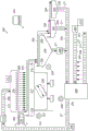
figure 1 illustrates an apparatus capable of blanching biomass according to a specific example embodiment of the present disclosure;
FIG. 2 illustrates an apparatus capable of blanching biomass according to a specific example embodiment of the present disclosure;
FIG. 3 is a flow diagram illustrating a method for cultivating, harvesting, and processing a microcrop to produce a high-concentration protein product, according to a specific example embodiment of the present disclosure;
FIG. 3A is a flow chart illustrating a method for blanching a microcrop to produce a high-concentration protein product according to a specific example embodiment of the present disclosure; and is
Fig. 4 is a flow diagram illustrating a method for cultivating, harvesting, and processing a microcrop to produce a high-concentration protein product, according to a specific example embodiment of the present disclosure.
Detailed Description
In some embodiments, the present disclosure relates to methods and apparatus for blanching (e.g., continuously) a microcrop to produce a high concentration protein product. According to some embodiments, the present disclosure relates to high concentration protein products obtained using a method or apparatus for blanching (e.g., continuously) a microcrop (e.g., lemna).
Microcrop
In some embodiments, the microcrop may include a single aquatic species (e.g., lemna, salvinia). The microcrop may comprise lemna (e.g., duckweed (duckweed)), Spirodela (Spirodela), Wolffia (Landoltia), Wolffia flabellaria (Wolfiella), Salvinia (Salvinia) (e.g., fern (floating fern)), Wolffia (wolfia) (e.g., Wolffia (watermeal)), Azolla (Azolla) (e.g., rhododendron (mosquito fern)), salvia (Pistia) (e.g., water lettuce (water lette)), or any combination thereof. According to some embodiments, the microcrop may be Lemna, e.g., Lemna microphylla (Lemna minor), Lemna obscura, Lemna gibba (Lemna minuta), Lemna valdiviana, or Lemna aequinoctialis. According to some embodiments, the microcrop may comprise a combination of two or more aquatic species. In some embodiments, the microcrop may be selected from a local aquatic species based on identified composition and growth characteristics that have been developed under local environmental conditions. Local species may override other species in an open pond or bioreactor based on their adaptation to local environmental conditions. In some embodiments, the microcrop may be adjusted in response to seasonal variations in temperature and light availability.
Microcrop may have beneficial properties (e.g., rapid growth rate, reduced nutritional requirements, ease of harvesting and/or processing, enhanced amino acid profile, enhanced palatability, reduced evapotranspiration, increased protein composition) compared to other aquatic species.
For example, lemna is one of the free-floating aquatic plants from the lemnaceae family (e.g., lemna), which grow rapidly. Duckweed proteins have an essential amino acid profile that is closer to animal proteins than most other plant proteins. Table 1 shows a typical essential amino acid composition profile of duckweed protein. Additionally, lemna provides high protein yields, and freshly harvested lemna contains, on a dry weight basis, up to about 43% protein. Furthermore, duckweed leaves have low fiber content (e.g., about 5% to about 15% on dry matter) and are very digestible, even for monogastric animals, compared to most other plants. This is in contrast to the composition of many crop species (e.g., soybean, rice, corn) that have a fiber content of about 50% and low digestibility.
Table 1: essential amino acid profile concentration of duckweed protein
| Essential amino acids | Protein (g/100g) |
| Lysine | 5.9 |
| Leucine | 9.7 |
| Isoleucine | 5.1 |
| Methionine | 2.4 |
| Phenylalanine | 6.3 |
| Threonine | 4.4 |
| Tryptophan | 2.0 |
| Valine | 6.3 |
| Histidine | 2.7 |
| Arginine | 6.8 |
Processing the microcrop (e.g., lemna) may result in a high protein concentrate product having improved quality and/or composition (e.g., better protein content, better PDCASS value, better digestibility, better amino acid profile, desired fiber content, and/or reduced oxalic acid content) relative to the unprocessed microcrop product. In some embodiments of the present disclosure, the operation of processing the microcrop may comprise an operation of blanching the microcrop.
Apparatus for blanching microcrop
Fig. 1 and 2 illustrate an example embodiment of an apparatus 100/200 for blanching (e.g., continuously blanching) a microcrop, according to some embodiments of the present disclosure. According to some embodiments, biomass 104/204 may be moved (e.g., by transportation, by gravity, by liquid flow) through apparatus 100/200 at a product flow rate ratio calculated by dividing the pump speed by the feed rate. For example, a device 100/200 operating at a pump speed of 28 liters per minute (L/min) and a feed rate of 4kg per minute (kg/min) results in a product flow rate ratio of 7: 1. According to some embodiments, apparatus 100/200 may have a product flow rate ratio of about 10:1, or about 9:1, or about 8:1, or about 7.5:1, or about 7:1, or about 6.5:1, or about 6:1, or about 5.5:1, or about 5:1, or about 4.5:1, or about 4:1, or about 3.5:1, or about 3:1, or about 2.5:1, or about 2:1, or about 1.5:1, or about 1:1, according to some embodiments. According to some embodiments, the plant 100/200 may include a central control system 102/202, the central control system 102/202 being operable to communicate with one or more elements of the plant, monitor one or more conditions (e.g., product flow ratio) and implement adjustments. In some embodiments, the central control system may be a programmable logic controller. In some embodiments, the central control system 102/202 may be in communication with a first meter (e.g., fig. 2222), a second meter (e.g., fig. 2229), a collection tank meter (e.g., fig. 2238), a pump and valve system (e.g., fig. 2248), or any combination thereof. In some embodiments, the central control system 102/202 may be operable to maintain and/or adjust product flow rate (e.g., 7:1), feed rate, pump rate, or any combination thereof.
As shown in fig. 1 and 2, an apparatus 100/200 for blanching a microcrop may include a transport mechanism 116/216 and a blanching tray 117/217. According to some embodiments, transport mechanism 116/216 may be operable to transport biomass (e.g., harvested microcrop, washed biomass) 104/204 to blanching tray 117/217. In some embodiments, transport mechanism 116/216 may comprise any mechanism that transports biomass 104/204 (e.g., lemna) to blanching tray 218. For example, in some embodiments, the transport mechanism 116/216 may comprise a transport belt or a series of transport belts. In some embodiments, transport mechanism 116/216 can comprise a slide or chute, wherein biomass 104/204 enters blanching tray 117/217 at least partially due to gravity.
In some embodiments, biomass 104/204 can be transported to blanching tray 117/217 at a feed rate. According to some embodiments, the feed rate may be regulated based on the overall size of the apparatus 100/200 and/or the pump speed to maintain a desired product flow rate ratio (e.g., 7: 1). In some embodiments, the feed rate may be about 0.5kg/min, or about 1kg/min, or about 1.5kg/min, or about 2kg/min, or about 3kg/min, or about 4kg/min, or about 5kg/min, or about 10kg/min, or about 20kg/min, or about 50kg/min, or about 100kg/min, or about 150kg/min, or about 200kg/min, or about 250kg/min, or about 300kg/min, or about 350kg/min, or about 400 kg/min.
As shown in fig. 1 and 2, in some embodiments, apparatus 100/200 may include a source 110/210, the source 110/210 operable to provide a blanching solution 106/206 to one or more elements of apparatus 100/200. In some embodiments, the source 110/210 may comprise a holding tank, chamber, water line, or any other container or system capable of storing and/or transporting liquid. According to some embodiments, the source 110/210 may contain and/or transport a blanching solution 106/206, the blanching solution 106/206 includes water, ground water, well water, distilled water, deionized water, reverse osmosis water, nanofiltration water, ultrafiltration water, or any combination thereof. In some embodiments, source 110/210 may contain and/or transport blanching solution 106/206, which blanching solution 106/206 includes at least one dissolved solid (e.g., ash). In some embodiments, the source 110/210 can contain and/or transport a blanching solution 106/206, the blanching solution 106/206 including a calcium salt (e.g., calcium chloride, calcium acetate). In some embodiments, the source 110/210 can contain and/or transport a blanching solution 106/206, which blanching solution 106/206 is exposed to the microcrop, collected, and reused (e.g., recycled blanching solution (e.g., fig. 2235)).
As shown in fig. 1 and 2, in some embodiments, apparatus 100/200 may comprise a conduit system 111/211. Piping 111/211 directly or indirectly connects the various components of apparatus 100/200 to one another and provides conduits through which liquids (e.g., blanching solutions, separated solutions, settling solutions) can be conveyed. For example, piping 111/211 can directly or indirectly connect source 110/210 to applicator 114/214 (e.g., a shower) such that blanching solution 106/206 can be delivered from the source to the applicator. In some embodiments, the duct system 111/211 may be composed of metal (e.g., steel, stainless steel, copper, lead), PVC, plastic, or any combination thereof. The duct system 111/211 may be rigid, flexible, or semi-flexible. According to some embodiments, the duct system 111/211 may be at least partially insulated. Liquid (e.g., blanching solution 106/206) may be conveyed through piping system 111/211 (e.g., from source 110/210 to applicator 114/214) under the influence of any force (e.g., gravity, pumping, pressurized air flow) or combination of forces. The conduit system 111/211 may be a single element or a series of elements without departing from the scope of the present disclosure. Moreover, the scope of the present disclosure encompasses the possibility that additional components (e.g., meters, pumps) may be dispersed along the conduit system 111/211.
According to some embodiments, applicator 114/214 may include any element or combination of elements operable to allow blanching solution 106/206 to exit applicator 114/214 (e.g., in the form of a controlled stream) and contact blanching tray 117/217 and/or biomass 104/204. For example, in some embodiments, applicator 114/214 may be a shower. In some embodiments, the applicator 114/214 may be operable to release the blanching solution as a waterfall (cascade), a shower (shower), a spray (spray), a mist (mist), a fog (fog), a pour (pour), a droplet, or any combination thereof. In some embodiments, the spreader 114/214 can include a body having an inlet and at least one aperture. According to some embodiments, the inlet may be operable to accept an input source (e.g., a pipe system 111/211) wherein the input source is capable of carrying a liquid (e.g., a blanching solution 106/206). In some embodiments, the applicator 114/214 can be operable to direct a flow of liquid (e.g., a blanching solution) from an inlet to at least one aperture such that at least some of the liquid exits the applicator through the at least one aperture. The at least one aperture may be of any size and/or shape. In some embodiments, at least one pore may be a porous screen, a porous material (e.g., a polyester filter cloth), or any combination thereof. According to some embodiments, the applicator 114/214 may be configured to stream a blanching solution through at least one aperture at a selected droplet size and/or volume (e.g., stream size). For example, in some embodiments, applicator 114/214 can be configured to stream blanching solution 106/206 at a droplet or stream size of about 5 μ L, or about 10 μ L, or about 20 μ L, or about 30 μ L, or about 40 μ L, or about 50 μ L, or about 100 μ L, or about 200 μ L. According to some embodiments, applicator 114/214 can be configured such that blanching solution 106/206 is poured at a droplet size and rate such that a stream of blanching solution exits applicator 114/214. In some embodiments, the applicator 114/214 can include a body including a tank, an inlet coupled to a top surface of the tank and receiving an input source, and at least one aperture on a bottom surface of the tank. In some embodiments, the size of the at least one aperture may be 3/16 inches (about 0.5 cm). According to some embodiments, the pores may be adjacent to a layer of porous material, such as a polyester filter cloth (e.g., 3/16 inches (about 0.5cm) thick).
In some embodiments, applicator 114/214 can be operable to stream blanching solution 106/206 in a controlled flow pattern such that a selected volume of blanching solution is streamed over a selected period of time. For example, in some embodiments, the applicator 114/214 may be operable to apply a spray at a rate of at least 0.5L/min, or at least 1L/min, or at least 2L/min, or at least 3L/min, or at least 4L/min, or at least 5L/min, or at least 6L/min, or at least 7L/min, or at least 8L/min, or at least 10L/min, or at least about 25L/min, or at least about 50L/min, or at least about 100L/min, or at least about 200L/min, or at least about 300L/min, or at least about 500L/min, or at least about 750L/min, or at least about 1000L/min, or at least about 1500L/min, or at least about 2000L/min, or at least about 2250L/min, or at least about 2500L/min.
In some embodiments, the apparatus 100/200 for blanching (e.g., continuously blanching) a microcrop may further comprise a heating element 112/212, the heating element 112/212 operable to heat a blanching solution 106/206, a separated solution (e.g., fig. 2235), a diluted solution (e.g., fig. 2208), or any combination thereof. The heating element 112/212 may be placed in various locations throughout the device 100/200 without departing from the scope of the present disclosure. For example, in some embodiments, the heating element may be directly or indirectly connected to source 110/210, or piping system 111/211, or applicator 114/214, or holding tank 136/236, or dilution source 142/242, or any combination thereof. According to some embodiments, blanching solution 106/206, a separated solution (e.g., fig. 2235), a diluted solution (e.g., fig. 2208), or any combination thereof, may enter heating element 112/212, bypass heating element 112/212, or otherwise interact with heating element 112/212 to form a heated blanching solution. As shown in fig. 1, in some embodiments, a heating element 112 can be incorporated within the source 110 or adjacent to the source 110 (e.g., a heating element incorporated within a holding tank) such that the blanching solution 106 can be heated at the source 110 or adjacent to the source 110. According to some embodiments, heating element 112/212 may be incorporated in or adjacent to one or more points along piping system 111/211 such that blanching solution 106/206 may be heated as it is conveyed from source 110/210 to applicator 114/214. As shown in fig. 2, in some embodiments, heating element 112/212 can be incorporated in applicator 114/214 or adjacent applicator 114/214 such that blanching solution 106/206 can be heated after being conveyed through pipe 111/211. In some embodiments, device 100/200 may have multiple heating elements, and the location of each heating element is independently selected. For example, in some embodiments, apparatus 100/200 can have a first heating element incorporated in applicator 114/214 or adjacent applicator 114/214 and a second heating element incorporated in dilution source 142/242 or adjacent dilution source 142/242.
According to some embodiments, the heating element 112/212 may be operable to heat the blanching solution 106/206 to a temperature of at least 60 ℃, or at least 65 ℃, or at least 70 ℃, or at least 75 ℃, or at least 80 ℃, or at least 85 ℃, or at least 90 ℃, or at least 95 ℃, or at least 100 ℃.
According to some embodiments, blanching tray 117/217 may be oriented to receive a volume of blanching solution 106/206 exiting applicator 114/214 (e.g., through at least one aperture). Blanching tray 117/217 may be operable to contain biomass 104/204 (e.g., first portion, second portion) and/or a volume of blanching solution 106/206. The blanching tray 117/217 may have any dimensions and composition suitable for its operability. According to some embodiments, the shape of the blanching tray 117/217 may be square or rectangular. In some embodiments, blanching tray 117/217 may have a first side 118/218 opposite a second side 119/219, and a third side opposite a fourth side, wherein the first, third, and fourth sides each have a first height, and the second side has a second height that is less than the first height. For example, in some embodiments, the second side can be a weir operable to maintain a desired volume of blanching solution in the blanching tray. According to some embodiments, the upper edge of the second side may comprise one or more notches. In some embodiments, the blanching tray 117/217 may have a depth of about 0.5cm, or about 1cm, or about 2cm, or about 3cm, or about 4cm, or about 5cm, or about 6cm, or about 8cm, or about 10cm, where "about" may be, for example, plus or minus 1 cm. According to some embodiments, the second side of the blanching tray may have a height of about 0.5cm less than the height of the first side of the blanching tray, or about 1cm less, or about 2cm less, or about 3cm less, or about 4cm less, or about 5cm less than the height of the first, third, and fourth sides of the blanching tray, wherein "about" may be, for example, plus or minus 0.5 cm.
According to some embodiments, the blanching tray 117/217 may be temporarily (e.g., located on a surface of a transport system) or fixedly attached to a transport system, such as a conveyor belt. In some embodiments, such a transport system may be used to drive blanching tray 117/217 in a direction such that blanching solution 106/206 is poured from applicator 114/214 into blanching tray 117/217. In other embodiments, blanching tray 117/217 may be stationary and applicator 114/214 may be positioned such that at least a portion of the series of blanching solutions 106/206 exiting applicator 114/214 enter blanching tray 117/217.
As shown in fig. 1 and 2, apparatus 100/200 may include a vibrating mechanism 120/220, which vibrating mechanism 120/220 is capable of vibrating blanching tray 117/217 to produce a net motion (e.g., wave motion) of a volume of blanching solution 106/206 within blanching tray 117/217. In some embodiments, vibrating mechanism 120/220 may be directly connected to blanching tray 117/217 or incorporated into the design of blanching tray 117/217. In other embodiments, vibrating mechanism 120/220 may be adjacent to blanching tray 117/217. For example, the vibrating mechanism 120/220 may include a platform suspended on a spring system 121/221 such that the blanching tray 117/217 may be attached (e.g., fixedly, removably) to the platform and thereby exposed to the generated vibratory forces (e.g., oscillations). In some embodiments, the vibrating mechanism 120/220 may be mounted directly on or coupled indirectly to the platform that is vibrating. In some embodiments, the vibrating mechanism 120/220 may include one or more single-axis motors, one or more stepper motors, one or more servo motors, one or more axis motor drives, one or more weights (e.g., balanced, unbalanced), or any combination thereof.
According to some embodiments, the vibrating mechanism 120/220 can produce a net movement of a volume of blanching solution 106/206. In some embodiments, the net movement of the volume of blanching solution 106/206 may generate a motive force capable of directing (e.g., pushing) biomass 104/204 from a first side of blanching tray 117/217 to a second side of blanching tray, wherein the first side is opposite the second side. In some embodiments, the second side of the blanching tray may have a height that is less than a height of the first side of the blanching tray (e.g., a weir); thereby allowing a volume of blanching solution and/or a mass of biomass to exit the blanching tray after being transported from the first side 118/218 to the second side 119/219 of the blanching tray.
In some embodiments, the net movement of the volume of blanching solution 106/206 may comprise a disturbance (e.g., wave, bump, swell, wave motion) on the upper surface of the volume of blanching solution. Disturbances (e.g., waves, bumps, swells) on the upper surface of the volume of blanching solution may be able to place any amount of blanching solution on the upper surface of biomass 104/204 (i.e., the surface facing away from the bottom surface of blanching tray 117/217). The net movement (e.g., wave motion) of the volume of blanching solution 106/206 may cause the upper surface of biomass 104/204 (i.e., the surface facing away from the bottom surface of blanching tray 117/217) to be covered (e.g., repeatedly covered, partially covered) by an amount of blanching solution 106/206. For example, when the perturbations (e.g., one or more waves) of the blanching solution fluctuate throughout the blanching tray 117/217, the net motion of a volume of blanching solution 106/206 (e.g., having fluctuations) may cause the upper surface of the biomass 104/204 to be repeatedly exposed to a volume of blanching solution. According to some embodiments, a mass of biomass 104/204 and/or a volume of blanching solution 106/206 may exit blanching tray 117/217 after being pushed from first side 118/218 of the blanching tray to a second side of the blanching tray. The net motion of exposing biomass 104/204 to a volume of blanching solution 106/206 (e.g., by fluctuating turbulence) may result in a more uniform blanching of the biomass.
According to some embodiments, apparatus 100/200 for blanching (e.g., continuous blanching) a microcrop may comprise a first meter 122/222. In some embodiments, first gauge 122/222 may be incorporated into blanching tray 118/218, or attached (e.g., removably, fixedly) to blanching tray 118/218, or adjacent to blanching tray 118/218. In some embodiments, the first meter 122/222 may be operable to measure one or more of the following: the volume of blanching solution 106/206 within blanching tray 118/218; mass of blanching tray endophyte 104/204; the volume of blanching solution exiting the blanching tray; the mass of biomass exiting the blanching tray; the temperature of the blanching solution within the blanching tray (e.g., average temperature, at a particular location); the temperature of the blanching solution exiting the blanching tray; a net rate of motion; the height and frequency of displacement (e.g., wave motion) of a volume of blanching solution; displacement of the blanching tray (e.g., relative to a set point on the platform); dissolved solids content (e.g., ash) of the blanching solution. In some embodiments, first meter 122/222 may be capable of communicating with heating element 112/212, applicator 114/214, vibrating mechanism 120/220, tank 136/236, pump and valve system 148/248, or any combination thereof (e.g., directly; via a central control system) such that a wide variety of conditions may be adjusted, including: the rate of flow of the blanching solution from applicator 114/214, the temperature of blanching solution 106/206 exiting the applicator, the net rate of movement, the dilution ratio (i.e., the ratio of diluting the separated solution), or any combination thereof. According to some embodiments, first meter 122/222 may be in communication with one or more components of apparatus 100/200 (e.g., directly, through a central control system) to maintain or adjust a desired product flow rate ratio (e.g., 7:1) or dilution ratio (e.g., 2.5: 1).
As shown in fig. 1, according to some embodiments, after being pushed from a first side 118 of the blanching tray to a second side 119 of the blanching tray (where the first side is opposite the second side), a mass of biomass 104 and/or a volume of blanching solution 106 may exit the blanching tray (e.g., via a weir) and enter a dewatering mechanism 134. In some embodiments, the dewatering mechanism may be operable to separate the blanching solution 106 from the blanched biomass 146. In some embodiments, the blanching solution 106 may be separated from the blanched biomass 146 using gravity separation, drainage, inclined screens, vibrating screens, filtration, decanter centrifuges, belt presses, fan presses, rotary presses, screw presses, filter presses, fine presses, or any combination thereof.
As shown in fig. 2, according to some embodiments, after being pushed from a first side 118 of the blanching tray to a second side 119 of the blanching tray (where the first side is opposite the second side), a mass of biomass 204 and/or a volume of blanching solution 206 may exit the blanching tray (e.g., via a weir) and enter a settling tank 224. The settling tank 224 can be directly or indirectly connected to the blanching tray 218 in such a way that a mass of biomass 204 and a volume of blanching solution 206 can flow into the settling tank 224 (e.g., gravity flow, propulsion). According to some embodiments, the settling tank 224 may be oriented relative to the blanching tray 218 in such a way that a mass of biomass 204 (e.g., first portion, second portion) and a volume of blanching solution 206 may flow into the settling tank 224 (e.g., gravity flow, propulsion). The settling tank 224 may be operable to allow contaminants and/or debris to become deposited from the mass of biomass 204 and sink below the surface of the settling solution. In some embodiments, settling tank 224 may be operable to remove non-buoyant solids from biomass 204. In some embodiments, the non-buoyant solid may comprise a freshwater arthropod or mollusk (e.g., leptopanaeus and snails). In some embodiments, the manipulation of the vital forms not required for blanching may result in a change in the buoyancy of those vital forms such that the previously buoyant vital forms become non-buoyant.
The precipitation tank 224 may have any dimensions and composition suitable for its operability. According to some embodiments, the shape of the settling tank may be square or rectangular (e.g., when viewed from above). In some embodiments, the precipitation tank 224 may have a first side 225 opposite a second side 226, and a third side opposite a fourth side, wherein the first, third, and fourth sides each have a first height, and the second side 226 has a second height that is less than the first height. For example, in some embodiments, the second side 226 can be a weir operable to maintain a desired volume of blanching solution in a blanching tray. According to some embodiments, the upper edge of the second side may comprise one or more notches. In some embodiments, the precipitation tank 224 may have a depth of about 5cm, or about 7.5cm, or about 10cm, or about 12.5cm, or about 15cm, or about 17.5cm, or about 20cm, or about 22.5cm, or about 25cm, or about 30cm, or about 35cm, or about 40cm, or about 45cm, or about 50cm, where "about" may represent, for example, plus or minus 2 cm.
In some embodiments, the precipitation tank 224 may contain a volume of precipitation solution. The precipitation solution may comprise any liquid having characteristics that allow the contaminants and/or residue to sink off the upper surface of the precipitation solution. According to some embodiments, the precipitation solution may include a blanching solution 206. In some embodiments, the precipitation solution may include water, ground water, well water, distilled water, deionized water, reverse osmosis water, nanofiltration water, ultrafiltration water, or any combination thereof. In some embodiments, the precipitation solution may be selected to have a particular viscosity.
In some embodiments, settling tank 224 may comprise one or more sloped sides and/or a sloped floor that may help remove contaminants, debris, or non-buoyant solids that sink below the surface of the settling solution. In some embodiments, the settling tank 224 may contain a filter or screen that may help separate the biomass from the debris, contaminants, and/or non-buoyant solids. For example, in some embodiments, the precipitation tank may comprise a screen throughout the surface of the precipitation tank but below the upper surface of the precipitation solution. In some embodiments, the screen may comprise a mesh size that is small enough to retain the biomass but large enough to allow at least some of the debris, contaminants, and/or non-buoyant solids to pass through. In some embodiments, the screen may be capable of vibratory motion such that the biomass may be transported from a first side 225 of the settling tank to a second side 226 of the settling tank, wherein the first and second sides are opposing. According to some embodiments, a mass of debris, contaminants, and/or non-buoyant solids may be discharged from the settling tank 224 (e.g., from the bottom of the settling tank) along with a volume of settling solution. In some embodiments, filter 228 may collect debris, contaminants, and/or non-buoyant solids, and the settling solution stream may be collected in collection tank 236 (e.g., as separated solution 235).
According to some embodiments, the debris, contaminants, and/or non-buoyant solids may settle to the bottom of the settling tank. In some embodiments, debris, contaminants, and/or non-buoyant solids may be recycled (e.g., used in microcrop cultivation systems, fish food).
In some embodiments, the settling tank 224 can include a propulsion mechanism operable to transport the biomass (e.g., first portion, second portion) from a first side 225 of the settling tank to a second side 226 of the settling tank, wherein the first side and the second side are opposite one another. In some embodiments, the propulsion mechanism may comprise gravity, paddle wheels, bubbling, underwater or surface jets, underwater mixers, vibrating mechanisms, or any combination thereof. In some embodiments, the propulsion mechanism may comprise a pump operable to pump the precipitation solution from the inlet to the outlet of the precipitation tank.
According to some embodiments, the settling tank 224 may be operable to cool the biomass. For example, the precipitation solution within the precipitation tank 224 may have a temperature that is less than the temperature of the blanching solution 206 (e.g., less than about 60 ℃) or less than room temperature (e.g., about 23 ℃). In some embodiments, the precipitation solution, when used, may have a temperature of less than about 90 ℃, or less than about 80 ℃, or less than about 70 ℃, or less than about 60 ℃, or less than about 50 ℃, or less than about 40 ℃, or less than about 30 ℃, or less than about 20 ℃. In some embodiments, the precipitation solution, when used, may have a temperature between about 20 ℃ and about 80 ℃, or between about 40 ℃ and about 60 ℃, or between about 20 ℃ and about 40 ℃, or between about 20 ℃ and about 30 ℃.
In some embodiments, the apparatus 200 for blanching (e.g., continuously) a microcrop may comprise a second gauge 229. In some embodiments, the second meter 229 may be incorporated into the settling tank 224, or attached (e.g., removably, fixedly) to the settling tank 224, or adjacent to the settling tank 224.
In some embodiments, the second meter 229 may be operable to monitor, maintain, and/or adjust a desired product flow rate ratio (e.g., 7: 1). In some embodiments, the second meter 229 may be operable to measure one or more of the following: the volume of the precipitation solution in the precipitation tank 224; the mass of biomass 204 in the settling tank; the volume of the precipitation solution leaving the precipitation tank; the mass of biomass exiting the settling tank; the temperature of the precipitation solution in the precipitation tank (e.g., average temperature, at a particular location); the temperature of the precipitation solution leaving the precipitation tank; the dissolved solids content (e.g., ash) of the precipitation solution. In some embodiments, the second gauge 229 can be capable of communicating (e.g., directly; via a central control system) with the heating element 112/212, the applicator 114/214, the vibrating mechanism 120/220, the trough 136/236, the pump and valve system, or any combination thereof, such that a wide variety of conditions can be adjusted. According to some embodiments, the second meter 229 may be in communication with one or more components of the device 100/200 (e.g., directly, through a central control system) to maintain or adjust a desired product flow rate ratio (e.g., 7:1) or dilution ratio (e.g., 2: 1).
As shown in fig. 2, after being pushed from a first side 225 of the settling tank to a second side 226 of the settling tank (where the first side is opposite the second side), a mass of biomass 204 and/or a volume of settling solution may exit the settling tank and enter a dewatering mechanism 234. As shown in fig. 1, in some embodiments, after being pushed from a first side 118 of the blanching tray to a second side 119 of the blanching tray (where the first side is opposite the second side), a mass of biomass 204 and/or a volume of blanching solution 106 may exit the blanching tray and enter a dewatering mechanism 234. Further, in some embodiments, biomass 204 may be placed directly into dewatering mechanism 234 without being transported from the first side to the second side of the blanching tray or settling tank. For example, in some embodiments, a blanching tray containing biomass and blanching solution may be directly emptied (e.g., chute feed, gravity feed) into a dewatering mechanism without departing from the scope of the present disclosure. In some embodiments, the dewatering mechanism may be operable to separate the blanching solution 106, the precipitation solution, the rinse solution, or any combination thereof (individually and collectively "separated solution" 135/235) from the blanched biomass 146. In some embodiments, dewatering mechanism 234 may comprise the use of gravity separation, drainage, inclined screens, vibrating screens, filtration, decanter centrifuges, belt presses, fan presses, rotary presses, screw presses, filter presses, fine presses, or any combination thereof.
As shown in fig. 1 and 2, in some embodiments, separated solution 135/235 may be collected and reused/recycled. According to some embodiments, as shown in fig. 1 and 2, separated solution 135/235 may be conveyed (e.g., gravity, pumped) to collection tank 136/236. The collection trough 136/236 may be of any size, shape, dimension, or composition suitable for collecting and retaining liquid. Separated solution 135/235 within collection tank 236 may be stationary or moving (e.g., agitated, propelled). In some embodiments, the apparatus 100/200 may have a single tank that may be operable to serve as both a source 110/210 and a collection tank 136/236.
As shown in fig. 1 and 2, an apparatus 100/200 for blanching a microcrop may comprise a collection tank meter 138/238. In some embodiments, the collection tank meter 138/238 may be operable to monitor, maintain, and/or adjust a desired product flow rate ratio (e.g., 7: 1). In some embodiments, the collection tank meter 138/238 may be operable to monitor the composition (e.g., total dissolved solids) and/or temperature of the separated solution. Monitoring the composition of the separated solution may comprise monitoring one or more of the following: total dissolved solids, total solids, turbidity, conductivity, nutrient (e.g., nitrogen) composition, salt content, pH. In some embodiments, the collection tank meter 238 may be in communication with (e.g., directly, indirectly) a pump and valve system 248 to regulate the composition of the separated solution (e.g., by adjusting the dilution ratio).
In some embodiments, the collection tank meter 138/238 may be capable of communicating (e.g., directly; through a central control system) with one or more components of the apparatus 100/200 (e.g., a pump and valve system, dilution tank) to maintain and adjust the total dissolved solids content of the volume of separated solution 135/235 stored in the tank 136/236. For example, in some embodiments, the collection tank meter 138/238 can be in communication with one or more components of the apparatus 100/200 to maintain or adjust the total solids content of the volume of separated solution 135/235 and/or the volume of blanching solution 106/206 at a value of less than 0.5% (w/w), or less than 1% (w/w), or less than 2% (w/w), or less than 4% (w/w), or less than 6% (w/w), or less than 8% (w/w), or less than 10% (w/w). According to some embodiments, the collection tank meter 138/238, in some embodiments, can communicate with one or more components of the apparatus 100/200 to maintain or adjust the turbidity value (e.g., relative to the absorption of a 500nm light source, where 1.0 is equivalent to 10% absorption, and 10.0 is equivalent to 100% absorption) of the volume of separated solution 135/235 and/or the volume of blanching solution 106/206 at a value of less than about 0.5, or less than about 0.75, or less than about 1.0, or less than about 1.25, or less than about 1.5, where about can represent plus or minus 5%. In some embodiments, the collection tank meter 138/238, in some embodiments, can be in communication with one or more components of apparatus 100/200 to maintain or adjust the conductivity value of the separated solution at or to a value of less than about 2000 μ S/cm, or less than about 2500 μ S/cm, or less than about 3000 μ S/cm, or less than about 3500 μ S/cm, or less than about 4000 μ S/cm, or less than about 4500 μ S/cm, or less than about 5000 μ S/cm, or less than about 5500 μ S/cm, or less than about 6000 μ S/cm, where "about" can represent plus or minus 250 μ S/cm. According to some embodiments, collection meter 138/238 can be in communication with one or more components of apparatus 100/200 (e.g., directly, through a central control system) to maintain or adjust a desired product flow rate ratio (e.g., 7: 1).
According to some embodiments, the device 100/200 may comprise a filter operable to filter the separated solution. According to some embodiments, the filter may be operable to achieve coarse filtration (e.g., gravity filtration, vibrating screen filtration), fine filtration (e.g., microfiltration, ultrafiltration, nanofiltration, reverse osmosis filtration), or any combination thereof. The filtered separated solution may be recycled as a wash solution, as a growth medium in the cultivation of the microcrop, as a blanching solution, as a precipitation solution, as a rinsing solution, or any combination thereof. In some embodiments, blanching waste (e.g., retentate from a filtration process) may be recycled as part of the growth medium (e.g., as a nutrient source) in the cultivation of the microcrop.
In some embodiments, separated solution 135/235 may be diluted prior to recycling operations (e.g., recycled as a blanching solution). Dilution of separated solution 135/235 may be desirable to adjust the composition of the separated solution (e.g., dissolved solids content, turbidity). In some embodiments, the diluted separated solution may be recycled as a blanching solution 106/206, as a wash solution (e.g., figure 4457), as a precipitation solution, as a rinse solution, or any combination thereof. In some embodiments, waste solution 143/243 may be recycled as growth medium in the cultivation of a microcrop (e.g., fig. 4450).
As shown in fig. 1 and 2, in some embodiments, an apparatus for blanching a microcrop may comprise a dilution source 142/242, the dilution source 142/242 operable to store and release a dilution solution 108/208. According to some embodiments, the dilute solution 108/208 may comprise water, ground water, well water, distilled water, deionized water, reverse osmosis water, nanofiltered water, ultrafiltration water, or any combination thereof. In some embodiments, the dilution source 142/242 may comprise a holding tank, chamber, water line, or any other container or system capable of storing a liquid. In some embodiments, diluting the separated solution may include discarding a volume of the separated solution (i.e., waste solution 143/243) from the collection tank. According to some embodiments, waste solution 143/243 may have a volume equal to the volume of dilution solution necessary to obtain the desired composition of dissolved solids (e.g., ash). In some embodiments, waste solution 143/243 may have a volume that is higher than the volume of dilution solution necessary to obtain the desired composition of dissolved solids (e.g., ash). The rate at which a volume of separated solution is discarded from the collection tank (e.g., total tank volume) can be regulated by a collection tank meter.
According to some embodiments, separated solution 135/235 and/or blanching solution 106/206 in tank 136/236 may be diluted to include dissolved solids (e.g., ash) and/or a desired composition of total solids. In some embodiments, the volume of separated solution 135/235 and/or the volume of blanching solution 106/206 in tank 136/236 may be diluted to have a total solids content at a value of less than 0.5% (w/w), or less than 1% (w/w), or less than 2% (w/w), or less than 4% (w/w), or less than 6% (w/w), or less than 8% (w/w), or less than 10% (w/w). According to some embodiments, the separated solution 135/235 in tank 136/236 can be diluted to have a turbidity value of the volume of separated solution 135/235 and/or the volume of blanching solution 106/206 at a value of less than about 0.5, or less than about 0.75, or less than about 1.0, or less than about 1.25, or less than about 1.5 (e.g., relative to the absorption of a 500nm light source, where 1.0 is equivalent to 10% absorption and 10.0 is equivalent to 100% absorption), where about can represent plus or minus 5%. In some embodiments, the separated solution 135/235 and/or blanching solution 106/206 in tank 136/236 may be diluted to have a conductivity value of less than about 2000 μ S/cm, or less than about 2500 μ S/cm, or less than about 3000 μ S/cm, or less than about 3500 μ S/cm, or less than about 4000 μ S/cm, or less than about 4500 μ S/cm, or less than about 5000 μ S/cm, or less than about 5500 μ S/cm, or less than about 6000 μ S/cm, where "about" may represent plus or minus 250 μ S/cm.
In some embodiments, separated solution 135/235 in tank 136/236 can be diluted relative to the feed rate of the biomass. For example, a device 100/200 with a feed rate of 4kg/min may have a dilution rate of separated solution 135/235 in tank 136/236 of 8L/min, resulting in a diluted feed ratio of 2: 1. According to some embodiments, apparatus 100/200 may have a feed dilution ratio of about 4:1, or about 3.5:1, or about 3:1, or about 2.5:1, or about 2:1, or about 1.5:1, or about 1:1, according to some embodiments.
As shown in fig. 1 and 2, in some embodiments, an apparatus 100/200 for blanching (e.g., continuously) a microcrop may comprise a pump and valve mechanism 148/248. According to some embodiments, the pump and valve mechanism 148/248 may be operable to propel one or more of the blanching solution, the precipitation solution, the rinsing solution, the separated solution, and the diluting solution within the apparatus 100/200. In some embodiments, the pump and valve mechanism 148/248 can be in communication with the first meter, the second meter, the collection tank meter 138/238, or any combination thereof. According to some embodiments, pump and valve mechanism 148/248 can communicate with one or more components of apparatus 100/200 (e.g., directly, through a central control system) to maintain or adjust a desired product flow rate ratio (e.g., 7: 1).
As shown in fig. 1 and 2, the device 100/200 may contain a heat exchanger 144/244. According to some embodiments, the heat exchanger 144/244 (e.g., a thermal energy exchange mechanism) may reduce the total energy input required for producing a high concentration protein product (e.g., protein flakes) from a microcrop (e.g., lemna, wolffia). According to some embodiments, the heat exchanger 144/244 may include a flow system in which the waste solution stream 143/243 (i.e., donor stream) and the dilute solution stream (i.e., recipient stream) from the collection tank 136/236 are adjacent such that thermal energy exchange may occur. In some embodiments, the dilute solution stream (i.e., the recipient stream) may have a cooler temperature and thus a lower thermal energy than the donor stream (e.g., the discard solution stream 143/243, which retains heat from the blanching solution). According to some embodiments, the heat exchanger may comprise a flow system (e.g., a series of pipes composed of a transitive material) such that the dilute solution stream (i.e., the recipient stream) may absorb at least some of the thermal energy from the waste solution stream 143/243 (i.e., the donor stream). In some embodiments, heat exchanger 144/244 can cause the temperature of the diluted solution stream and/or the diluted separated solution in tank 136/236 to increase. In some embodiments, heat exchanger 144/244 may reduce the amount of energy required for heating the recirculated solution in heating element 212.
As shown in fig. 2, according to some embodiments, the blanched biomass 246 can be transported to the rinsing mechanism 230 after being separated from the blanching solution 206 and/or the precipitation solution. The rinsing mechanism 230 may be directly or indirectly connected to the dewatering mechanism 234 in such a way that the blanched biomass 246 may be transported into the rinsing mechanism 230 by gravity or propulsion.
In some embodiments, the rinsing mechanism 230 may be operable to remove unwanted dissolved solids from the blanched biomass 246. The rinsing mechanism 230 may have any dimensions and composition suitable for its operability. In some embodiments, the rinsing mechanism may comprise a sprayer and a vibrating screen. According to some embodiments, the rinsing mechanism may comprise a rinse tank having any suitable dimensions of shape. In some embodiments, the rinse tank 230 can have a depth of at least about 5cm, or at least about 10cm, or at least about 15cm, or at least about 20cm, or at least about 25cm, where "about" can be, for example, plus or minus 3 cm. In some embodiments, the rinse mechanism 230 may be capable of containing the blanched biomass 246 and/or a volume of rinse solution. According to some embodiments, the rinse mechanism 230 (e.g., rinse tank) may be operable to receive a rinse solution such that the rinse solution contacts at least one surface of the blanched biomass 246 within the rinse mechanism. In some embodiments, the rinse mechanism 230 (e.g., rinse tank) may contain a volume of rinse solution such that the blanched biomass 246 floats on the surface of the rinse solution. In other embodiments, the rinsing mechanism may comprise a sprayer mechanism such that a volume of rinsing solution is placed on at least one surface of the blanched biomass 246. In some embodiments, the rinsing mechanism may further comprise a vibrating screen such that at least some of the rinsing solution may be removed from the blanched biomass.
According to some embodiments, the rinse solution may comprise water, distilled water, reverse osmosis water, nanofiltration water, the blanching solution 206, a precipitation solution, a recycled blanching solution, a recycled precipitation solution, a recycled rinse solution, or any combination thereof. According to some embodiments, the rinse solution may be sterilized (e.g., UV radiation, filtration, heating).
In some embodiments, the rinsing mechanism 230 may be operable to cool the blanched biomass 246. For example, the rinse solution within the rinse tank 230 may have a temperature less than the temperature of the blanching solution 206 or less than ambient temperature. In some embodiments, the rinse solution may have a temperature below room temperature (e.g., about 12 ℃) at the time of use. In some embodiments, the rinse solution, when used, may have a temperature of less than about 50 ℃, or less than about 40 ℃, or less than about 30 ℃, or less than about 20 ℃, or less than about 15 ℃, or less than about 10 ℃, or less than about 5 ℃, or less than about 2 ℃, or less than about 1 ℃, or less than about 0 ℃.
In some embodiments, the rinsing mechanism 230 can include a propulsion mechanism operable to transport the blanched biomass from a first side of the rinsing mechanism to a second side of the rinsing mechanism, wherein the first side and the second side are opposite one another. For example, in some embodiments, the rinse mechanism may comprise a propulsion system and a rinse tank, wherein the propulsion mechanism propels the blanched biomass from a first side of the rinse tank to a second side of the rinse tank. In other embodiments, the rinsing mechanism 230 may comprise a vibrating screen and sprayer system, wherein the vibrating screen pushes the blanched biomass from the first side to the second side. According to some embodiments, the propulsion mechanism of the rinsing mechanism may comprise gravity, paddle wheels, bubbling, underwater or surface jets, underwater mixers, vibrating mechanisms, or any combination thereof.
As shown in fig. 1 and 2, in some embodiments, the rinse mechanism 230 can comprise a component (e.g., a shaker) capable of separating a volume of rinse solution and blanched biomass to produce a separated solution 235. According to some embodiments, the separated solution may be collected in a collection tank 236, diluted, filtered, recycled, or any combination thereof.
Method for producing high concentration protein products by blanching of microcrop
Cultivation of microcrop
In some embodiments, the microcrop may be clonally propagated (e.g., cultivated) by contacting the microcrop with a first medium (e.g., an aqueous nutrient composition, a growth medium) under conditions that allow for expansion. According to some embodiments, the microcrop may be cultivated in a bioreactor system (e.g., fig. 3350, fig. 4450). According to some embodiments, the bioreactor system may contain a first medium (e.g., a growth medium) that includes water and/or a nutrient composition. In some embodiments, the nutritional composition may comprise at least one of nitrogen, phosphorus, potassium, and calcium. In some embodiments, the first medium may comprise dissolved gaseous oxygen and/or dissolved gaseous carbon dioxide. According to some embodiments, the first medium may be configured to have an increased calcium composition (e.g., an increased calcium growth medium). For example, the first medium of increased calcium may include a calcium concentration of greater than or equal to about 120 parts per million (ppm), or greater than or equal to about 115ppm, or greater than or equal to about 110ppm, or greater than or equal to about 105ppm, or greater than or equal to about 100ppm, or greater than or equal to about 95ppm, or greater than or equal to about 90ppm, or greater than or equal to about 85ppm, or greater than or equal to about 80ppm, or greater than or equal to about 75ppm, or greater than about 70ppm, or greater than or equal to about 65ppm, or greater than or equal to about 60ppm, or greater than or equal to about 55ppm, or greater than or equal to about 50ppm, or greater than or equal to about 45ppm, or greater than or equal to about 40ppm, or greater than about 35ppm, or greater than or equal to about 30ppm, or greater than about 25ppm, or greater than or equal to about 20ppm, wherein "about" comprises plus or minus 10%. In some embodiments, the first medium of increased calcium may comprise a calcium concentration of about 20ppm to about 120ppm, about 25ppm to about 120ppm, or about 30ppm to about 120ppm, or about 40ppm to about 120ppm, or about 50ppm to about 120ppm, or about 60ppm to about 120ppm, or about 70ppm to about 120ppm, or about 80ppm to about 120ppm, or about 20ppm to about 100ppm, or about 30ppm to about 100ppm, or about 40ppm to about 100ppm, or about 50ppm to about 100ppm, or about 60ppm to about 100ppm, or about 70ppm to about 100ppm, or about 80ppm to about 100 ppm. According to some embodiments, the first medium of increased calcium may comprise a calcium concentration of at least about 20ppm (e.g., ± 10%). In some embodiments, the first medium of increased calcium comprises at least about 100ppm calcium. The bioreactor system may be configured to add additional nutrients (e.g., nitrogen, phosphorus, potassium, calcium) or gases (e.g., oxygen, carbon dioxide) to the first medium at a prescribed time indicator or in response to sensor readings. In some embodiments, the calcium may include calcium, calcium carbonate, calcium oxalate, calcium oxide, calcium citrate, calcium carbide, calcium phosphate, calcium sulfate, calcium chloride, or a combination thereof.
In some embodiments, the first medium may include one or more anti-photosynthetic dyes configured to attenuate photosynthetically active radiation within the growth medium. According to some embodiments, one or more anti-photosynthetic dyes may be added in sufficient volume or concentration to inhibit the growth of at least one other aquatic organism (e.g., an underwater aquatic species, phytoplankton, photosynthetic algae (phytoalgae), epiphytic algae). The anti-photosynthetic dye may comprise at least one of: (n-ethyl-n- [4- [ [4- [ ethyl [ (3-sulfophenyl) methyl ] methyl)]Amino group]-phenyl radical](2-sulfophenyl) -methylene)]2, 5-cyclohexadiene-1-ylidene]-3-sulfobenzylamine hydroxideInner salt, disodium salt, (color index acid blue 9 (reference 42090)), (4E) -5-oxo-1- (4-sulfonylphenyl) -4- [ (4-sulfonylphenyl) hydrazono]Trisodium 3-pyrazolecarboxylate (colour index yellow 23 (reference number 19140)), diazo compound; 2- [ [4- [ ethyl- [ (3-sulfonylphenyl) methyl ] methyl]Amino group]Phenyl radical]- [4- [ ethyl- [ (3-sulfonylphenyl) methyl ] methyl]Ammonium subunit]-2, 5-cyclohexadien-1-ylidene]Methyl radical]Benzenesulfonate (2- [ [4- [ ethyl- [ (3-sulfonatophynyl) methyl)]amino]phenyl]-[4-[ethyl-[(3-sulfonatophenyl)methyl]azaniumylidene]cyclohexa-2,5-dien-1-ylidene]methyl]benzanesulfonate) (color index acid blue 34 (reference number 42645)); benzyl- [4- [ [4- (benzyl (ethyl) amino)]Phenyl radical]- (5-hydroxy-2, 4-disulfophenyl) methylene]-2, 5-cyclohexadien-1-ylidene]-ethylammonium (color index acid blue 5 (reference 42052)); disodium 2- (1, 3-dioxoinden-2-yl) quinoline-6, 8-disulfonate (color index acid yellow 3 (reference number 15985)), and (n-ethyl-n- [4- [ [4- [ ethyl [ (3-sulfophenyl) methyl ] ethyl]Amino group]-phenyl radical](2-sulfophenyl) -methylene)]2, 5-cyclohexadiene-1-ylidene]-3-sulfobenzylamine hydroxide inner salt, disodium salt and (4E) -5-oxo-1- (4-sulfonylphenyl) -4- [ (4-sulfonylphenyl) hydrazono]Trisodium (E) -3-pyrazolecarboxylic acid A mixture of (a). Other suitable anti-photosynthetic dyes can be found in tables I and II of Wilson, U.S. patent No. 4,042,367, which is incorporated herein by reference.
According to some embodiments, a first culture medium (e.g., an aqueous nutrient composition) may be provided and/or added in a bioreactor (e.g., a pond) and may be maintained at a desired set point level (e.g., specific volume). In some embodiments, the bioreactor system may be configured to collect rainfall and/or take water from the ground, or recycled water sources (e.g., stormwater, recycled water), or any other suitable water source. According to some embodiments, the bioreactor system may further comprise additional storage containers (e.g., containers or ponds) for excess growth medium.
In some embodiments, one or more smaller bioreactors (e.g., ponds) may be designed and sized to function adequately as a "feeder" bioreactor for larger bioreactors. In some embodiments, the smaller bioreactors may be seeded first and grown to high density, at which point they may optimally seed the larger bioreactors in a manner that supports faster growth.
In some embodiments, the bioreactor system may include a monitoring system. In some embodiments, the monitoring system may be configured to display and/or provide one or more user alerts regarding one or more bioreactor conditions (e.g., nutrient concentration, pH, dissolved oxygen level, growth medium level, microcrop profile, flow rate, temperature) and/or adjust operating conditions (e.g., growth medium flow rate and/or time and/or amount of nutrient addition; feed microcrop addition, oxygen or carbon dioxide addition). Adjustments may be made continuously, semi-continuously, periodically, intermittently at a specified or variable time or any other interval as desired. In some embodiments, the adjustment may be selected to optimize growth rate and/or yield of the aquatic species. For example, a microcrop species may be grown in a large-scale, open bioreactor with a monitoring system configured to adjust the introduction of materials (e.g., fresh or recycled water, fresh or recycled growth media) based on, for example, exposure to light, such that the nutrient consumption rate may be regulated.
In some embodiments, the bioreactor system may include a single container in which the microcrop may be cultivated. In some embodiments, the bioreactor system may include a plurality of cultivation containers that may be connected, partially connected, or disconnected. In some embodiments, a bioreactor (e.g., a pond) may be an earthen pond having a bank of compacted dirt removed from the inner bottom of the bioreactor. According to some embodiments, the bioreactor may be a man-made vessel (e.g., metal, plastic, resin). The bioreactor system may comprise an open bioreactor, a closed bioreactor, a semi-open bioreactor, or any combination thereof. In some embodiments, the bioreactor system may be configured to divide one or more vessels into channels or chambers. In some embodiments, the bioreactor system may be configured to allow flow of growth media. In some embodiments, the bioreactor system may comprise a propulsion system (e.g., paddle wheel, bubble, underwater or surface jet, underwater mixer) and/or a recirculation system. In some embodiments, the bioreactor system may be configured to adjust the flow rate of the growth medium (e.g., to redistribute nutrient concentrations or microcrop growth patterns).
In some embodiments, the bioreactor system may be an open (e.g., horizontal relative to ground) bioreactor vessel (e.g., a curved raceway) such that growth media contained within the bioreactor vessel and/or a microcrop growing on an upper surface of the growth media may be exposed to wind originating from outside the bioreactor vessel. According to some embodiments, the bioreactor system may be partially open (e.g., relative to ground level), with at least 90% or at least 80%, or at least 70%, or at least 60%, or at least 50%, or at least 40%, or at least 30%, or at least 20%, or at least 10% of the upper surface of the contained culture medium being open. According to some embodiments, the upper surface may be open, wherein the surface is substantially free (e.g., free) of any coverings or other barriers, wherein the surface is directly exposed to ambient weather conditions, wherein there is substantially no film, glass, cover, or other barrier between the surface and the atmosphere (whether such barrier has pores or openings), and/or wherein the ambient atmosphere is the only space occupant proximate to or directly above the surface at a distance of at least about 1 meter.
In some embodiments, the bioreactor system may monitor and adjust the thickness and distribution of the microcrop pad. For example, the bioreactor system may initiate the harvest process when the microcrop reaches a specified thickness or profile. In some embodiments, a minimum thickness of the microcrop mat may be maintained such that a desired transpiration rate of the growth medium within the bioreactor system may be maintained. In some embodiments, a minimum thickness of the microcrop may be maintained such that less sunlight is able to penetrate the surface of the growth medium (i.e., reduce the vigor of the underwater aquatic species (e.g., algae)).
The microcrop may be grown by any suitable method, not limited to the methods described herein. Various changes may be made to the method of cultivating the microcrop without departing from the scope of the present disclosure.
Harvesting of micro-crops
As shown in fig. 3 and 4, the microcrop may be harvested 351/451, in whole or in part, at any desired time or times to form biomass 352/452. For example, the microcrop may be harvested at one or more specified times, at regular or irregular intervals, and/or continuously. The selection of one or more harvest times and/or time intervals may be based on environmental conditions (e.g., precipitation, relative humidity, temperature range, average, low or high threshold and/or light intensity, wavelength range, exposure time) and/or microcrop exhibiting one or more desired characteristics (e.g., mat thickness, mat distribution, maturity). The operation of harvesting the microcrop may be manual or automated. In some embodiments, an automatic skimmer system (skimmer system) may collect the microcrop from the bioreactor system and transfer (e.g., via a pumping system) the harvested microcrop onto an inclined shaker screen to separate the biomass from the growth medium and debris. In some embodiments, the microcrop may be harvested by vacuum skimming the microcrop from the bioreactor system through a fixed or moving screen filter. According to some embodiments, a biomass slurry comprising a harvested microcrop (e.g., lemna) and a growth medium (e.g., water) may be transported to an inclined shaker screen, where the biomass (e.g., microcrop) may be separated from the growth medium.
As shown in fig. 3 and 4, during harvesting, the separated growth nutrients may be recycled 353/453 back to the bioreactor system or to an additional storage container (e.g., container or pond), according to some embodiments. In some embodiments, at least about 40%, or at least about 50%, or at least about 60%, or at least about 70%, or at least about 80%, or at least about 90%, or at least about 95% of the growth medium (e.g., water) separated from the biomass may be recycled for further use in cultivating, harvesting, and/or processing the microcrop. In some embodiments, the operation of recycling the separated growth medium may comprise an operation of filtering the separated growth medium by coarse filtration (e.g., gravity filtration, vibrating screen filtration), fine filtration (e.g., microfiltration, ultrafiltration, nanofiltration, reverse osmosis filtration), or any combination thereof.
Soaking and/or buffering the pH of biomass
Following the harvesting operation, the biomass may be soaked (e.g., figure 4454) and/or buffered. Operations to soak and/or buffer the harvested biomass can help reduce the oxalic acid content of the protein product. In some embodiments, the operation of soaking and/or buffering the harvested biomass may help to reduce the oxalic acid and/or oxalate content of the protein product.
In some embodiments, the harvested biomass can be soaked in a second medium (e.g., figure 4454). According to some embodiments, the second culture medium may comprise water (e.g., ground water, surface water, recycled water), distilled water, reverse osmosis or nanofiltration water, and/or a nutrient composition. In some embodiments, the second medium may comprise any desired portion of the recycled fluid. For example, the second culture medium can comprise at least about 10% (v/v), at least about 20% (v/v), at least about 30% (v/v), at least about 40(v/v), at least about 50% (v/v), at least about 60% (v/v), at least about 70% (v/v), at least about 80% (v/v), or at least about 90% (v/v) of fluid recycled from another stage of the process.
According to some embodiments, the second medium may be configured to have a low nitrogen composition (e.g., a low nitrogen second medium). For example, the low nitrogen second medium can include less than or equal to about 20 parts per million (ppm), less than or equal to about 18ppm, less than or equal to about 16ppm, or less than or equal to about 14ppm, or less than or equal to about 12ppm, or less than or equal to about 10ppm, or less than or equal to about 9ppm, or less than or equal to about 8ppm, or less than or equal to about 7ppm,or less than about 6ppm, or less than about 5ppm, or less than about 4ppm, or less than about 3ppm, or less than about 2ppm, or less than about 1ppm, or less than about 0.5ppm, or about 0ppm nitrogen concentration. In some embodiments, the low nitrogen second medium may comprise a nitrogen concentration of about 0ppm to about 20ppm, or about 0.5ppm to about 15ppm, or about 0.5ppm to about 10ppm, or about 1ppm to about 9ppm, or about 1ppm to about 7ppm, or about 1ppm to about 6ppm, or about 1ppm to about 5ppm, or about 3ppm to about 6ppm, or about 2ppm to about 8 ppm. According to some embodiments, the low nitrogen second medium may comprise a nitrogen concentration of up to about 10ppm (e.g., ± 1 ppm). In some embodiments, the low nitrogen second medium may include a nitrogen concentration of up to about 5ppm (e.g., ± 0.5 ppm). In contrast, for example, with no detectable nitrogen (i.e., N)2) The nitrogen-free second culture medium, the low nitrogen second culture medium may include at least some amount of nitrogen. In some embodiments, the second medium may be a nitrogen-free second medium.
According to some embodiments, the second medium may be configured to have a low calcium composition (e.g., a low calcium second medium). For example, the low calcium second medium can include a calcium concentration of less than or equal to about 20ppm, less than or equal to about 18ppm, less than or equal to about 16ppm, or less than or equal to about 14ppm, or less than or equal to about 12ppm, or less than or equal to about 10ppm, or less than or equal to about 9ppm, or less than or equal to about 8ppm, or less than or equal to about 7ppm, or less than or equal to about 6ppm, or less than or equal to about 5ppm, or less than or equal to about 4ppm, or less than or equal to about 3ppm, or less than or equal to about 2ppm, or less than or equal to about 1ppm, or less than or equal to about 0.5ppm, or about 0 ppm. In some embodiments, the low calcium second medium may comprise a calcium concentration of about 0ppm to about 20ppm, or about 0.5ppm to about 15ppm, or about 0.5ppm to about 10ppm, or about 1ppm to about 9ppm, or about 1ppm to about 7ppm, or about 1ppm to about 6ppm, or about 1ppm to about 5ppm, or about 3ppm to about 6ppm, or about 2ppm to about 8 ppm. According to some embodiments, the low-calcium second medium may comprise a calcium concentration of up to about 10ppm (e.g., ± 1 ppm). In some embodiments, the low-calcium second medium can include a calcium concentration of up to about 5ppm (e.g., ± 0.5 ppm). In some embodiments, soaking the biomass in the low calcium second medium can affect the balance between the oxalic acid concentration and the oxalate concentration (e.g., calcium oxalate).
In some embodiments, the second medium can be configured to have a high calcium composition (e.g., a high calcium second medium). For example, the high calcium second medium may comprise a calcium concentration of less than or equal to about 800ppm, or less than or equal to about 750ppm, or less than or equal to about 700ppm, or less than or equal to about 650ppm, or less than or equal to about 600ppm, or less than or equal to about 550ppm, or less than or equal to about 500ppm, or less than or equal to about 450ppm, or less than or equal to about 400ppm, or less than or equal to about 350ppm, or less than or equal to about 300ppm, or less than or equal to about 250ppm, or less than or equal to about 200ppm, or less than or equal to about 150ppm, or less than or equal to about 100ppm, or less than or equal to about 50 ppm. In some embodiments, the high calcium second medium may comprise a calcium concentration of about 50ppm to about 200ppm, or about 50ppm to about 400ppm, or about 50ppm to about 600ppm, or about 100ppm to about 800ppm, or about 100ppm to about 700ppm, or about 100ppm to about 600ppm, or about 100ppm to about 500ppm, or about 300ppm to about 600ppm, or about 200ppm to about 800 ppm. According to some embodiments, the high calcium second medium may comprise a calcium concentration of up to about 800ppm (e.g., ± 50 ppm). In some embodiments, the high calcium second medium can include a calcium concentration of up to about 600ppm (e.g., ± 50 ppm). In some embodiments, soaking the biomass in the high calcium second medium can affect the balance between the oxalic acid concentration and the oxalate concentration (e.g., calcium oxalate). For example, soaking the biomass in a high calcium second medium can convert oxalic acid to oxalate.
In some embodiments, the second medium can be configured to have a low calcium composition and a low nitrogen composition (e.g., a low nitrogen and calcium growth medium). For example, the low nitrogen and calcium growth medium may include a calcium concentration of less than or equal to about 20ppm, or less than or equal to about 18ppm, or less than or equal to about 16ppm, or less than or equal to about 14ppm, or less than or equal to about 12ppm, or less than or equal to about 10ppm, or less than or equal to about 9ppm, or less than or equal to about 8ppm, or less than or equal to about 7ppm, or less than or equal to about 6ppm, or less than or equal to about 5ppm, or less than or equal to about 4ppm, or less than or equal to about 3ppm, or less than or equal to about 2ppm, or less than or equal to about 1ppm, or less than or equal to about 0.5ppm, or about 0 ppm. Low nitrogen and calcium growth media may include a nitrogen concentration of less than or equal to about 20ppm, or less than or equal to about 18ppm, or less than or equal to about 16ppm, or less than or equal to about 14ppm, or less than or equal to about 12ppm, or less than or equal to about 10ppm, or less than or equal to about 9ppm, or less than or equal to about 8ppm, or less than or equal to about 7ppm, or less than or equal to about 6ppm, or less than or equal to about 5ppm, or less than or equal to about 4ppm, or less than or equal to about 3ppm, or less than or equal to about 2ppm, or less than or equal to about 1ppm, or less than or equal to about 0.5ppm, or about 0 ppm. In some embodiments, the low nitrogen and calcium second medium may comprise a calcium concentration of about 0ppm to about 20ppm, or about 0.5ppm to about 20ppm, or 0.5ppm to about 15ppm, or 0.5ppm to about 10ppm, or about 1ppm to about 9ppm, or about 1ppm to about 7ppm, or about 1ppm to about 6ppm, or about 1ppm to about 5ppm, or about 3ppm to about 6ppm, or about 2ppm to about 8 ppm. In some embodiments, the low nitrogen and calcium second medium may comprise a nitrogen concentration of about 0ppm to about 20ppm, or about 0.5ppm to about 20ppm, or 0.5ppm to about 15ppm, or 0.5ppm to about 10ppm, or about 1ppm to about 9ppm, or about 1ppm to about 7ppm, or about 1ppm to about 6ppm, or about 1ppm to about 5ppm, or about 3ppm to about 6ppm, or about 2ppm to about 8 ppm. According to some embodiments, the low nitrogen and calcium second medium may comprise a calcium concentration of up to about 10ppm (e.g., ± 1 ppm). In some embodiments, the low nitrogen and calcium second medium can include a calcium concentration of up to about 5ppm (e.g., ± 0.5 ppm). According to some embodiments, the low nitrogen and calcium second medium may comprise a nitrogen concentration of up to about 10ppm (e.g., ± 1 ppm). In some embodiments, the low nitrogen and calcium second medium may include a nitrogen concentration of up to about 5ppm (e.g., ± 0.5 ppm). In some embodiments, soaking the biomass in a low nitrogen and low calcium second medium can affect the balance between oxalic acid concentration and oxalate concentration (e.g., calcium oxalate).
According to some embodiments, the operation of soaking the biomass (e.g., figure 4454) may include an operation of immersing the biomass in a second medium to form a biomass slurry. In some embodiments, the biomass may be soaked for about 1 hour, or about 2 hours, or about 4 hours, or about 6 hours, or about 8 hours, or about 10 hours, or about 12 hours, or about 16 hours, or about 20 hours, or about 24 hours, or about 36 hours, or about 48 hours, or about 60 hours, or about 72 hours, or about 84 hours, or about 96 hours, or about 108 hours, or about 120 hours, or about 132 hours, or about 144 hours. The operation of soaking the biomass may comprise agitating, flowing, moving, spraying, or stirring the second medium. According to some embodiments, a biomass slurry comprising the soaked microcrop (e.g., lemna) and a second medium (e.g., a low nitrogen second medium) may be transported to an inclined shaker screen, where the biomass (e.g., microcrop) may be separated from the second medium.
According to some embodiments, the biomass may be buffered in a third medium according to some embodiments. According to some embodiments, the third medium may comprise water (e.g., ground water, surface water, recycled water), distilled water, reverse osmosis water, and/or nanofiltration water. In some embodiments, the third medium may comprise any desired portion of the recycled fluid. For example, the third culture medium can comprise at least about 10% (v/v), at least about 20% (v/v), at least about 30% (v/v), at least about 40% (v/v), at least about 50% (v/v), at least about 60% (v/v), at least about 70% (v/v), at least about 80% (v/v), or at least about 90% (v/v) of the fluid recycled from another stage of the process (e.g., from a filtered effluent stream).
According to some embodiments, the operation of buffering the pH of the biomass may include an operation of immersing the biomass in a third medium to form a biomass slurry. In some embodiments, the biomass may be buffered for about 1 hour, or about 2 hours, or about 4 hours, or about 6 hours, or about 8 hours, or about 10 hours, or about 12 hours, or about 16 hours, or about 20 hours, or about 24 hours, or about 36 hours, or about 48 hours. According to some embodiments, a biomass slurry comprising a buffered microcrop (e.g., lemna) and a third medium (e.g., distilled water, ground water, surface water, rainwater) may be transported to an inclined shaker, where the biomass (e.g., microcrop) may be separated from the third medium. In other embodiments, the biomass (e.g., microcrop) may be separated from the third medium by drainage.
According to some embodiments, the operation of buffering the pH of the biomass may comprise an operation of changing (e.g., increasing, decreasing) or maintaining the pH value of the biomass. In some embodiments, buffering the biomass may include altering (e.g., increasing, decreasing) or maintaining the pH of the biomass below about 8.0, or below about 7.5, or below about 7.0, or below about 6.5, or below about 6.0, or below about 5.5, or below about 5.0, or below about 4.5, or below about 4.0, or below about 3.5, or below about 3.0. According to some embodiments, buffering the biomass may include changing (e.g., increasing, decreasing) or maintaining the pH of the biomass in the following ranges: from about 3.0 to about 7.5, or from about 3.5 to about 7.5, or from about 4.0 to about 7.5, or from about 4.5 to about 7.5, or from about 5.0 to about 7.5, or from about 5.5 to about 7.5, or from about 6.0 to about 7.5, or from about 6.5 to about 7.5. As will be appreciated by one of ordinary skill in the art, buffering the biomass by adjusting the pH of the biomass can promote protein stability, and in some embodiments, higher protein production as compared to unbuffered biomass.
One or more of the soaked biomass and buffered biomass produced in one procedure may be stored in its respective vessel (e.g., soaking vessel, buffering vessel) before being fed to one or more downstream procedures or equipment. This may accommodate different operating schedules or modes including, for example, a continuous mode, a batch mode, or multiple feed streams to one or more downstream processes and/or one or more downstream equipment. For example, in some embodiments, biomass may be harvested and processed (e.g., soaking operations and/or buffering operations) during daylight hours, and then the processed biomass may be further processed (e.g., cracking operations, separation operations) in smaller batches (e.g., first portion, second portion) to accommodate capacity limitations of downstream processing machinery.
Washing biomass
As shown in fig. 4, in some embodiments, the operation of processing the microcrop or biomass (e.g., first portion, second portion) may comprise a washing procedure 455 to remove excess growth medium, solvent solution, debris, contaminants, microorganisms, and/or toxins. Washing the biomass can increase the purity and/or yield of the protein product. The washing procedure can disinfect and/or repel pests, reduce or remove bacteria, fungi, viruses, insects, and any combination thereof on or around the surface of the biomass. In some embodiments, the washing procedure can be performed by exposing (e.g., immersing, spraying) at least one surface of the biomass to a washing solution (e.g., water, growth medium, antimicrobial solution). In some embodiments, the wash solution can be combined with the biomass (e.g., first portion, second portion) to form a slurry.
In some embodiments, the wash solution may include any desired portion of the recycled fluid. For example, the wash solution can include at least about 10% (v/v), at least about 20% (v/v), at least about 30% (v/v), at least about 40% (v/v), at least about 50% (v/v), at least about 60% (v/v), at least about 70% (v/v), at least about 80% (v/v), or at least about 90% (v/v) of recycled (e.g., recycled wash solution, filtered blanching solution) from another stage of the process. In some embodiments, the wash solution may be an aqueous solution or a solvent. The wash solution may contain one or more antimicrobial agents, a de-infective compound, a fatty acid, an alcohol, chlorine, an oxidizing compound, and any combination thereof (e.g., ozonated water).
According to some embodiments, the wash solution may be applied at elevated temperature and/or pressure. The wash solution may remain in contact with the biomass for at least about 1 second, or at least about 5 seconds, or at least about 10 seconds, or at least about 20 seconds, or at least about 30 seconds, or at least about 1 minute, or at least about 5 minutes. In some embodiments, a second wash solution (e.g., water, ozonated water, recycled wash solution, filtered blanching solution) may be applied to the biomass. In some embodiments, a third wash solution (e.g., water, ozonated water, recycled wash solution, filtered blanching solution) may be applied to the biomass. The compositions of the first, second and third wash solutions may be the same or different from each other. In some embodiments, the first wash solution may be or may include a filtered blanching solution, the second wash solution may be water, and the third wash solution may be ozonated water. In some embodiments, some or all of the wash solution (e.g., the first, second, and/or third wash solutions) may be separated from the biomass (e.g., using an inclined screen or a vibrating screen).
In some embodiments, some or all of the wash solution, the second wash solution, and/or the third wash solution can be collected and reused/recycled (e.g., recycled wash solution), as shown in figure 4456. According to some embodiments, at least about 40%, or at least about 50%, or at least about 60%, or at least about 70%, or at least about 80%, or at least about 90%, or at least about 95% of the wash solution, second wash solution, and/or third wash solution (e.g., water) separated from the biomass may be recycled as recycled wash solution and/or as growth medium in a bioreactor system for future use.
In some embodiments, the wash solution, the second wash solution, and/or the third wash solution may have or may be adjusted to have any desired pH. For example, the pH of the wash solution, the second wash solution, and/or the third wash solution can be neutral or basic (e.g., about 7.0, or about 7.5, or about 8.0, or about 8.5, or about 9.0, or about 9.5, or about 10.0). According to some embodiments, the pH of the wash solution, the second wash solution, and/or the third wash solution may be from about 7.0 to about 7.5, or from about 7.5 to about 8.0, or from about 8.0 to about 8.5, or from about 8.5 to about 9.0, or from about 9.0 to about 9.5, or from about 9.5 to about 10.0. In some embodiments, the pH of the wash solution, the second wash solution, and/or the third wash solution may be from about 7.0 to about 10.0, or from about 7.0 to about 9.5, or from about 7.0 to about 9.0, or from about 7.0 to about 8.5, or from about 7.0 to about 8.0, or from about 7.0 to about 7.5.
The wash solution (e.g., the first, second, and/or third wash solutions) may have a temperature below room temperature (e.g., about 12 ℃) at the time of use. The wash solution is cooled and thereby the microcrop may increase protein recovery and/or decrease proteolytic activity. In some embodiments, the wash solution (e.g., the first, second, and/or third wash solutions) may have a temperature of less than about 30 ℃, or less than about 20 ℃, or less than about 15 ℃, or less than about 10 ℃, or less than about 5 ℃, or less than about 2 ℃, or less than about 1 ℃, or less than about 0 ℃ at the time of use. In some embodiments, the wash solution (e.g., the first, second, and/or third wash solution) may have a temperature between about 0 ℃ and about 10 ℃, or between about 5 ℃ and about 15 ℃, or between about 10 ℃ and about 20 ℃, or between 15 ℃ and about 25 ℃, or between about 20 ℃ and about 30 ℃ when in use.
Blanching biomass
As shown in fig. 3 and 4, in some embodiments, the operation of processing the microcrop or biomass (e.g., first portion, second portion) may comprise an operation of blanching microcrop material 358/458 (e.g., biomass) to form a blanched biomass 362/462. In some embodiments, for example, the seed may be (1) after a harvest operation (e.g., as shown in fig. 3); or (2) after harvesting and washing operations; or (3) after the harvesting and soaking operations; or (4) a blanching operation 358/458 is performed on the biomass after the harvesting, washing, and soaking operations (as shown in FIG. 4). According to some embodiments, the blanching procedure may be used instead of, or in addition to, the washing procedure. According to some embodiments, the blanching operation may reduce the ash content, oxalic acid content, and/or phenol (e.g., tannic acid) content of a high-concentration protein product (e.g., wet, flake/granule, powder). As shown in fig. 3A, according to some embodiments, the operation of blanching biomass 358 (e.g., first portion, second portion) may include an operation of transporting the biomass to a blanching tray 359 and an operation of contacting the biomass with a blanching solution 360 to form a blanched biomass 362. In some embodiments, blanching a biomass may comprise directing (e.g., pushing) the biomass from a first side of a blanching tray to a second side of the blanching tray, wherein the first side is opposite the second side 361.
Transporting biomass to blanching tray
The operation of transporting the biomass to the blanching tray 359 may be performed using a transport mechanism. In some embodiments, the transport mechanism may comprise a transport belt or a series of transport belts. In some embodiments, the transport mechanism may comprise a slide or chute, wherein the biomass enters the blanching tray at least partially due to gravity. According to some embodiments, the biomass may be transported to the blanching tray 359 at a desired feed rate. In some embodiments, the feed rate may be about 0.5kg/min, or about 1kg/min, or about 1.5kg/min, or about 2kg/min, or about 3kg/min, or about 4kg/min, or about 5kg/min, or about 10kg/min, or about 20kg/min, or about 50kg/min, or about 100kg/min, or about 150kg/min, or about 200kg/min, or about 250kg/min, or about 300kg/min, or about 350kg/min, or about 400 kg/min. In some embodiments, the feed rate may be regulated to maintain a desired product flow rate ratio (e.g., 7: 1).
According to some embodiments, the blanching tray may be oriented to receive a volume of blanching solution from a dispenser (e.g., fig. 1114) (e.g., a shower). The blanching tray may be capable of containing a biomass (e.g., a first portion, a second portion) and/or a volume of blanching solution. The blanching tray may have any dimensions and composition suitable for its operability. According to some embodiments, the shape of the blanching tray may be square or rectangular (e.g., when viewed from above). In some embodiments, a blanching tray may have a first side (e.g., fig. 1118) opposite a second side (e.g., fig. 1119), and a third side opposite a fourth side, wherein the first, third, and fourth sides each have a first height, and the second side has a second height that is less than the first height. For example, in some embodiments, the second side can be a weir operable to maintain a desired volume of blanching solution in the blanching tray. According to some embodiments, the upper edge of the second side may comprise one or more notches. In some embodiments, the blanching tray may have a depth of about 0.5cm, or about 1cm, or about 2cm, or about 3cm, or about 4cm, or about 5cm, or about 6cm, or about 8cm, or about 10cm, where "about" may be, for example, plus or minus 1 cm. According to some embodiments, the second side of the blanching tray may have a height of about 0.5cm less than the height of the first side of the blanching tray, or about 1cm less, or about 2cm less, or about 3cm less, or about 4cm less, or about 5cm less than the height of the first, third, and fourth sides of the blanching tray, wherein "about" may be, for example, plus or minus 0.5 cm.
Contacting a biomass with a blanching solution
As shown in fig. 3A, according to some embodiments, the operation 358 of blanching the biomass (e.g., first portion, second portion) may comprise an operation of contacting 360 the biomass with a blanching solution to form a blanched biota 362. In some embodiments, the contacting the biomass with the blanching solution operation 360 may comprise: (a) applying a blanching solution to at least one surface of the biomass (e.g., showering), (b) immersing (e.g., completely, partially) the biomass in a wave of blanching solution, or (c) a combination of (a) and (b).
According to some embodiments, the blanching solution may comprise water, ground water, well water, distilled water, reverse osmosis water, nanofiltration water, or any combination thereof. In some embodiments, the blanching solution may also comprise at least one dissolved solid (e.g., ash). According to some embodiments, the blanching solution may also include at least one calcium salt (e.g., calcium chloride, calcium acetate). Blanching a biomass with a blanching solution comprising at least one calcium salt (e.g., calcium chloride, calcium acetate) may remove at least some soluble oxalic acid from the biomass by conversion to insoluble calcium oxalate. In some embodiments, the calcium salt may be selected from calcium chloride, calcium acetate, calcium carbonate, calcium hydroxide, or combinations thereof. In some embodiments, the blanching solution may comprise (at least in part) a blanching solution that is exposed to the microcrop, collected, and reused (e.g., recycled blanching solution map 3369).
In some embodiments, the blanching solution may have a temperature of greater than about 60 ℃, or greater than about 65 ℃, or greater than about 70 ℃, or greater than about 75 ℃, or greater than about 80 ℃, or greater than about 85 ℃, or greater than about 90 ℃, or greater than about 95 ℃, or greater than about 100 ℃ when contacting the biomass.
Applying a blanching solution to at least one surface of a biomass
According to some embodiments, the operation 360 of contacting the biomass with the blanching solution may comprise an operation of applying the blanching solution to at least one surface of the biomass (e.g., showering). In some embodiments, the operation of applying the blanching solution may involve directing a volume of the blanching solution onto at least one surface of the biomass using an applicator. The applicator (e.g., fig. 1114) can be any element or combination of elements capable of applying a blanching solution to at least one surface of a biomass (e.g., a shower). For example, in some embodiments, the applicator (e.g., fig. 1114) can be a shower. In some embodiments, the applicator can apply the blanching solution to at least one surface of the biomass by pouring, showering, spraying, atomizing, spraying, pouring, dripping, or otherwise dispersing the blanching solution, or any combination thereof.
According to some embodiments, the blanching solution may be applied to at least one surface of the biomass in a selected droplet size and/or volume. For example, in some embodiments, the blanching solution may be applied to at least one surface of the biomass in a droplet size of about 5 μ L, or about 10 μ L, or about 20 μ L, or about 30 μ L, or about 40 μ L, or about 50 μ L, or about 100 μ L, or about 200 μ L. In some embodiments, the blanching solution may be applied at about 0.5L/min, or about 1L/min, or about 2L/min, or about 3L/min, or about 4L/min, or about 5L/min, or about 6L/min, or about 7L/min, or about 8L/min, or about 10L/min, or at least about 25L/min, or at least about 50L/min, or at least about 100L/min, or at least about 200L/min, or at least about 300L/min, or at least about 500L/min, or at least about 750L/min, or at least about 1000L/min, or at least about 1500L/min, or at least about 2000L/min, or at least about 2250L/min, or at least about 2500L/min, is applied to at least one surface of the biomass.
Immersing the biomass in a blanching solution wave
According to some embodiments, the operation 360 of contacting the biomass with the blanching solution may comprise an operation of immersing (e.g., completely, partially) the biomass in a wave of blanching solution within a blanching tray. The waves may include any disturbance (e.g., wave, bump, swell, or ripple (hereinafter "wave") on the upper surface of the volume of blanching solution) that may be capable of placing any amount of blanching solution on the upper surface of the biomass (i.e., the surface facing away from the bottom surface of the blanching tray 117/217).
A blanching tray (e.g., fig. 1117) may be operable to contain a biomass (e.g., a first portion, a second portion) and/or a volume of blanching solution. The blanching tray may have any dimensions and composition suitable for its operability. According to some embodiments, the shape of the blanching tray may be square or rectangular (e.g., when viewed from above). In some embodiments, a blanching tray (e.g., fig. 1117) may have a first side (e.g., fig. 1118) opposite a second side (e.g., fig. 1119), and a third side opposite a fourth side, wherein the first, third, and fourth sides each have a first height, and the second side has a second height that is less than the first height. For example, in some embodiments, the second side can be a weir operable to maintain a desired volume of blanching solution in the blanching tray. According to some embodiments, the upper edge of the second side may comprise one or more notches. In some embodiments, the blanching tray may have a depth of about 0.5cm, or about 1cm, or about 2cm, or about 3cm, or about 4cm, or about 5cm, or about 6cm, or about 8cm, or about 10cm, where "about" may be, for example, plus or minus 1 cm. According to some embodiments, the second side of the blanching tray may have a height of about 0.5cm less, or about 1cm less, or about 2cm less, or about 3cm less, or about 4cm less, or about 5cm less than the height of the first side of the blanching tray, wherein "about" may be, for example, plus or minus 1 cm. According to some embodiments, a blanching tray (e.g., fig. 1117) may be oriented to receive a volume of blanching solution exiting an applicator (e.g., fig. 1114 (e.g., a shower)).
In some embodiments, the wave of blanching solution within a blanching tray may be generated by a vibrating blanching tray mechanism that includes a blanching tray and a vibrating mechanism (e.g., fig. 1 and 2). According to some embodiments, a vibrating mechanism (e.g., fig. 1120) may be capable of vibrating a blanching tray (e.g., fig. 1117) to produce a net motion (e.g., a wave) of a volume of blanching solution within the blanching tray. In some embodiments, the vibrating mechanism (e.g., fig. 1120) can be directly connected to the blanching tray (e.g., fig. 1117) or incorporated into the design of the blanching tray (e.g., fig. 1117). In other embodiments, the vibrating mechanism may be adjacent to the blanching tray. For example, as shown in fig. 2, the vibrating mechanism 220 may include a platform suspended on a spring system 221 such that the blanching tray 217 may be attached (e.g., fixedly, removably) to the platform and thereby exposed to the generated vibratory force (e.g., oscillation). In some embodiments, the vibrating mechanism may be mounted directly on the vibrating platform or coupled indirectly to the vibrating platform. In some embodiments, the vibrating mechanism may include one or more single-axis motors, one or more stepper motors, one or more servo motors, one or more axis motor drives, one or more weights (e.g., balanced, unbalanced), or any combination thereof.
In some embodiments, the wave of blanching solution within a blanching tray may be generated by a vibrating mechanism (e.g., figure 1120) that generates a net movement of a volume of blanching solution. The waves may be capable of placing any amount of blanching solution on the upper surface of the biomass (i.e., the surface facing away from the bottom surface of the blanching tray 117/217). The wave of the volume of blanching solution may cause the biomass to be submerged (e.g., completely, partially). The operation of immersing the biomass in the wave of blanching solution may involve the upper surface of the biomass (i.e., the surface facing away from the bottom surface of the blanching tray) being covered (e.g., repeatedly covered, partially covered) by an amount of blanching solution 106/206. For example, when one or more waves (i.e., disturbances of the blanching solution (e.g., one or more waves) fluctuate throughout the blanching tray, the operation of immersing the biomass in the blanching solution wave may involve repeated exposure of the upper surface of the biomass to a volume of the blanching solution.
In some embodiments, the contacting the biomass with the blanching solution operation 360 may comprise both (a) applying the blanching solution to at least one surface of the biomass (e.g., showering) and (b) immersing the biomass in (e.g., fully, partially) a wave of the blanching solution.
Guiding biomass throughout a blanching tray
According to some embodiments, the operation 360 of contacting the biomass with the blanching solution may comprise an operation of directing (e.g., pushing) the biomass from a first side (e.g., fig. 1118) of a blanching tray (e.g., fig. 1117) to a second side (e.g., fig. 1119) of the blanching tray, wherein the first side is opposite the second side. In some embodiments, the net motion of the volume of blanching solution produced by the vibrating mechanism (e.g., figure 1120) may produce a motive force capable of directing (e.g., pushing) the biomass from a first side of the blanching tray to a second side of the blanching tray, wherein the first side is opposite the second side. In some embodiments, the second side of the blanching tray may have a height (e.g., a weir) that is less than the height of the first side of the blanching tray; thereby allowing a volume of blanching solution and/or a mass of biomass to exit the blanching tray after being transported from a first side (e.g., fig. 1118) to a second side (e.g., fig. 1119) of the blanching tray. According to some embodiments, a mass of biomass and/or a volume of blanching solution may exit the blanching tray after being pushed from a first side of the blanching tray to a second side of the blanching tray.
In some embodiments, directing (e.g., pushing) the biomass from a first side of the blanching tray to a second side of the blanching tray, wherein the first side is opposite the second side, may involve using gravity, paddle wheels, bubbling, underwater or surface jets, underwater mixers, vibrating mechanisms, or any combination thereof as the propulsion mechanism.
Blanching conditions and flow rates
According to some embodiments, the biomass may be contacted with the blanching solution (e.g., fig. 3a 360) for up to about 20 seconds (sec), or up to about 30sec, or up to about 40sec, or up to about 50sec, or up to about 1min 15sec, or up to about 1min 30sec, or up to about 1min 45sec, or up to about 2min 30sec, or up to about 3min, or up to about 4min, or up to about 5min, or up to about 6min, or up to about 7min, or up to about 8min, or up to about 9min, or up to about 10min, according to some embodiments. In some embodiments, the biomass can be contacted with the blanching solution (e.g., fig. 3a 360) for about 20sec to about 40sec, or about 30sec to about 45sec, or about 30sec to about 1min 30sec, or about 30sec to about 2min, or about 30sec to about 5min, or about 1min to about 10min, or about 30sec to about 10min, where "about" can be, for example, plus or minus 10%.
In some embodiments, the biomass may be contacted with a blanching solution having a temperature of about 85 ℃ for about 40 sec.
In some embodiments, the blanching solution may change temperature upon contacting the biomass. For example, according to some embodiments, the biomass may be contacted by a blanching solution having an initial temperature between about 92 ℃ and about 94 ℃, wherein the contacting is for a period of about 40sec, at which point the blanching solution may have a final contact temperature between about 75 ℃ and about 77 ℃. In some embodiments, the blanching solution, in some embodiments, may have an initial temperature (e.g., the temperature at which the blanching solution first contacts the biomass) of greater than about 60 ℃, or greater than about 65 ℃, or greater than about 70 ℃, or greater than about 75 ℃, or greater than about 80 ℃, or greater than about 85 ℃, or greater than about 90 ℃, or greater than about 95 ℃, or greater than about 100 ℃. In some embodiments, the blanching solution may have a final contact temperature (e.g., temperature at the time the biomass exits the blanching tray) of less than about 60 ℃, or less than about 65 ℃, or less than about 70 ℃, or less than about 75 ℃, or less than about 80 ℃, or less than about 85 ℃, or less than about 90 ℃, or less than about 95 ℃, or less than about 100 ℃.
In some embodiments, blanching the biomass operation 358 may be performed at a product flow rate ratio calculated by dividing the pump speed by the feed rate. For example, in some embodiments, the blanching solution may be pushed at a pump speed of 28 liters per minute (L/min) and the biomass may be transported at a feed rate of 4kg per minute (kg/min), resulting in a 7:1 product flow rate ratio. According to some embodiments, operation 358 of blanching the biomass may have a product flow rate ratio of about 10:1, or about 9:1, or about 8:1, or about 7.5:1, or about 7:1, or about 6.5:1, or about 6:1, or about 5.5:1, or about 5:1, or about 4.5:1, or about 4:1, or about 3.5:1, or about 3:1, or about 2.5:1, or about 2:1, or about 1.5:1, or about 1:1, according to some embodiments.
Monitoring blanching process
According to some embodiments, blanching the biomass may comprise monitoring one or more of: volume of blanching solution within a blanching tray (e.g., fig. 1117); the mass of biomass in the blanching tray; the volume of blanching solution exiting the blanching tray; the mass of biomass exiting the blanching tray; the temperature of the blanching solution within the blanching tray (e.g., average temperature, at a particular location); the temperature of the blanching solution exiting the blanching tray; the rate of net motion; the height and frequency of the undulations; dissolved solids content (e.g., ash) of the blanching solution. In some embodiments, blanching the biomass may comprise adjusting one or more of the following conditions in response to the monitored conditions: the rate of blanching solution exiting the applicator (e.g., fig. 1114), the temperature of blanching solution applied to the biomass, the rate of net movement, the dilution ratio (i.e., the ratio of diluting the separated solution), or any combination thereof. In some embodiments, monitoring the operation of the blanching process may include monitoring a device (e.g., first meter 122/222) in communication with one or more components of a central control system or blanching apparatus (e.g., diagram 1100) to maintain or adjust a desired product flow rate ratio (e.g., 7:1) or dilution ratio (e.g., 2.5: 1).
Precipitating blanched biomass
As shown in fig. 4, according to some embodiments, the method may include an operation 463 of precipitating the blanched biomass. In some embodiments, the operation 463 of precipitating the blanched biomass may occur in a precipitation tank (e.g., fig. 2224). According to some embodiments, after being pushed from a first side of a blanching tray to a second side of the blanching tray (where the first side is opposite the second side), the blanched biomass and/or a volume of blanching solution may exit the blanching tray and enter a settling tank (e.g., fig. 2224). In some embodiments, the settling tank can be directly or indirectly connected to a blanching tray in such a way that the blanched biomass and a volume of blanching solution can flow into the settling tank (e.g., gravity flow, propulsion).
The settling tank (e.g., fig. 2224) can have any dimensions and/or composition suitable for its operability. According to some embodiments, the shape of the settling tank (e.g., fig. 2224) may be square or rectangular. In some embodiments, a settling tank can have a first side (e.g., fig. 2225) opposite a second side (e.g., fig. 2226), and a third side opposite a fourth side, wherein the first, third, and fourth sides each have a first height, and the second side has a second height that is less than the first height. For example, in some embodiments, the second side can be a weir operable to maintain a desired volume of blanching solution in the blanching tray. According to some embodiments, the upper edge of the second side may comprise one or more notches. In some embodiments, a precipitation tank (e.g., fig. 2224) may have a depth of about 5cm, or about 7.5cm, or about 10cm, or about 12.5cm, or about 15cm, or about 17.5cm, or about 20cm, or about 22.5cm, or about 25cm, or about 30cm, or about 35cm, or about 40cm, or about 45cm, or about 50cm, where "about" may represent plus or minus 2.5 cm. In some embodiments, a settling tank (e.g., fig. 2224) may comprise one or more sloped sides and/or a sloped bottom that may help remove contaminants, debris, or non-buoyant solids that sink below the surface of the settling solution.
In some embodiments, the operation of precipitating the blanched biomass (e.g., figure 4463) may comprise exposing at least one surface of the blanched biomass to a precipitation solution. The precipitation solution may comprise any liquid having properties that allow the contaminants and/or residue to sink away from the upper surface of the precipitation solution. According to some embodiments, the precipitation solution may comprise a blanching solution. In some embodiments, the precipitation solution may include water, ground water, well water, distilled water, deionized water, reverse osmosis water, nanofiltration water, ultrafiltration water, or any combination thereof. In some embodiments, the precipitation solution may be selected to have a particular viscosity
In some embodiments, the operation 463 of precipitating the blanched biomass may comprise filtering the one or more non-buoyant solids from the precipitation tank. In some embodiments, a settling tank (e.g., fig. 2224) may contain a filter or screen that may help filter the biomass from debris, contaminants, and/or non-buoyant solids. For example, in some embodiments, the precipitation tank may comprise a screen throughout the surface of the precipitation tank but below the upper surface of the precipitation solution. In some embodiments, the screen may comprise a mesh size that is small enough to retain the biomass but large enough to allow at least some of the debris, contaminants, and/or non-buoyant solids to pass through. In some embodiments, the screen may be capable of vibratory motion such that the blanched biomass may be transported from a first side 225 of the settling tank to a second side 226 of the settling tank, wherein the first and second sides are opposing.
According to some embodiments, the operation of precipitating the blanched biomass (e.g., figure 4463) may comprise sludge, contaminants, and/or non-buoyant solids that precipitate to the bottom of the precipitation tank. In some embodiments, debris, contaminants, and/or non-buoyant solids may be recycled (e.g., used in microcrop cultivation systems, fish food).
According to some embodiments, the operation of precipitating the blanched biomass (e.g., figure 4463) may comprise an operation of cooling the blanched biomass. For example, the settling solution within the settling tank (e.g., figure 2224) can have a temperature (e.g., less than about 60 ℃) that is less than the temperature of the blanching solution (e.g., figure 2206), and thus, the blanched biomass cools when at least one surface of the blanched biomass is exposed to the settling solution. In some embodiments, the precipitation solution, when used, may have a temperature of less than about 90 ℃, or less than about 80 ℃, or less than about 70 ℃, or less than about 60 ℃, or less than about 50 ℃, or less than about 40 ℃, or less than about 30 ℃, or less than about 20 ℃. In some embodiments, the precipitation solution, when used, may have a temperature between about 20 ℃ and about 80 ℃, or between about 40 ℃ and about 60 ℃, or between about 20 ℃ and about 40 ℃, or between about 20 ℃ and about 30 ℃.
In some embodiments, the operation of precipitating the blanched biomass (e.g., figure 4463) can comprise monitoring the precipitation tank (e.g., using second meter figure 2229). In some embodiments, monitoring the operation of the settling tank may measure one or more of the following: the volume of the precipitation solution in the precipitation tank; the mass of the blanched biomass in the settling tank; the volume of the precipitation solution leaving the precipitation tank; the mass of blanched biomass exiting the settling tank; the temperature of the precipitation solution in the precipitation tank (e.g., average temperature, at a particular location); the temperature of the precipitation solution leaving the precipitation tank; the dissolved solids content (e.g., ash) of the precipitation solution. In some embodiments, monitoring operation of the settling tank (e.g., using second gauge graph 2229) can comprise a monitoring mechanism (e.g., second gauge graph 2229) in communication with the central control system and/or one or more components of the blanching apparatus (e.g., graph 2200). For example, a monitoring mechanism (e.g., second gauge graph 2229) can be in communication with a heating element (e.g., graph 2212), a applicator (e.g., graph 2214), a vibrating mechanism (e.g., graph 2220), a tank (e.g., graph 2236), a pump and valve system (e.g., graph 2248), or any combination thereof (e.g., directly, through a central control system) such that a wide variety of conditions can be adjusted. According to some embodiments, the operation of precipitating the blanched biomass (e.g., figure 4463) may include a monitoring mechanism (e.g., second meter profile 2229) in communication with the central control system and/or one or more elements of the blanching apparatus (e.g., figure 2200) to maintain or adjust a desired product flow rate ratio (e.g., 7:1) or dilution ratio (e.g., 2.5: 1).
In some embodiments, the operation of precipitating the blanched biomass (e.g., figure 4463) may comprise pushing the blanched biomass (e.g., first portion, second portion) from a first side of the settling tank (e.g., figure 2225) to a second side of the settling tank (e.g., figure 2226), wherein the first side and the second side are opposite one another. In some embodiments, the advancement of the blanched biomass may comprise an advancement mechanism using a settling tank. For example, according to some embodiments, the propulsion mechanism of the settling tank may comprise gravity, paddle wheels, bubbling, underwater or surface jets, underwater mixers, vibrating mechanisms, or any combination thereof. In some embodiments, the propulsion mechanism may comprise a pump operable to pump the precipitation solution from the inlet to the outlet of the precipitation tank.
According to some embodiments, directing (e.g., pushing) the biomass from the first side of the settling tank to the second side of the settling tank can result in a mass of biomass and/or a volume of settling solution exiting the settling tank and entering a dewatering mechanism (e.g., fig. 2234). In some embodiments, the dewatering mechanism can be directly or indirectly connected to the blanching tray or settling tank in such a way that a mass of biomass, a volume of blanching solution, and/or a volume of settling solution can flow into the dewatering mechanism (e.g., gravity flow, propulsion).
Dewatering blanched biomass
As shown in fig. 3 and 4, method 300/400 can include an operation 364/464 of dewatering the blanched biomass. According to some embodiments, the operation of dewatering the blanched biomass may occur (1) after the operation of blanching the biomass (e.g., fig. 3) or (2) after the operations of blanching the biomass and precipitating the blanched biomass (e.g., fig. 4).
In some embodiments, dewatering the blanched biomass may comprise separating the blanching solution, the precipitation solution, or any combination (individually and collectively "separated solution") from the blanched biomass (e.g., fig. 1 and 2135/235). In some embodiments, dewatering the blanched biomass may involve the use of a dewatering mechanism including, for example, gravity separation, drainage, inclined screens, vibrating screens, filtration, decanter centrifuges, belt presses, fan presses, rotary presses, screw presses, filter presses, fine presses, or any combination thereof.
According to some embodiments, after being pushed from a first side of a settling tank to a second side of the settling tank (where the first side is opposite the second side), a mass of blanched biomass and/or a volume of settling solution may exit the settling tank and enter a dewatering mechanism. In some embodiments, upon being pushed from a first side of a blanching tray to a second side of the blanching tray (where the first side is opposite the second side), a mass of blanched biomass and/or a volume of blanching solution may exit the blanching tray and enter a dewatering mechanism. In some embodiments, the method can comprise placing the blanched biomass into a dewatering mechanism without transporting from a first side to a second side of a blanching tray, a settling tank, or a rinsing mechanism. For example, in some embodiments, a blanching tray containing biomass and blanching solution may be directly emptied (e.g., chute feed, gravity feed) into a dewatering mechanism without departing from the scope of the present disclosure.
Rinsing the blanched biomass
According to some embodiments, a method may comprise an operation of rinsing (e.g., figure 4465) the blanched biomass. In some embodiments, rinsing (e.g., figure 4465) the blanched biomass can remove unwanted dissolved solids from the blanched biomass.
According to some embodiments, the operation of rinsing the blanched biomass may comprise an operation of exposing at least one surface of the blanched biomass to a rinse solution. According to some embodiments, exposing at least one surface of the blanched biomass to a rinse solution may involve placing the rinse solution on at least one surface of the biomass (where the biomass is on a shaker screen) through a sprayer nozzle and operating the shaker screen to remove at least some of the rinse solution. According to some embodiments, the operation of exposing at least one surface of the blanched biomass to the rinse solution may include an operation of floating the blanched biomass in a rinse tank (e.g., figure 2230) or immersing the blanched biomass in the rinse tank (e.g., figure 2230). The rinse tank may have any suitable dimensions or shape. In some embodiments, the rinse tank may have a depth of about 5cm, or about 7.5cm, or about 10cm, or about 12.5cm, or about 15cm, or about 17.5cm, or about 20cm, or about 22.5cm, or about 25cm, or about 30cm, or about 35cm, or about 40cm, or about 45cm, or about 50cm, where "about" may represent plus or minus 1 cm.
According to some embodiments, the rinse solution may comprise water, distilled water, reverse osmosis water, nanofiltration water, a blanching solution, a precipitating solution, a recycled blanching solution, a recycled precipitating solution, a recycled rinsing liquid, or any combination thereof. According to some embodiments, the rinse solution may be sterilized (e.g., UV radiation, filtration, heating). In some embodiments, a dilution solution (e.g., figure 2208) may be used as the rinse solution.
In some embodiments, rinsing (e.g., figure 4465) the blanched biomass can reduce the temperature of the blanched biomass. For example, the operation of rinsing the blanched biomass may comprise an operation of exposing at least one surface of the blanched biomass to a rinse solution having a temperature lower than the temperature of the blanched biomass. In some embodiments, the rinse solution may have a temperature below room temperature (e.g., about 12 ℃) at the time of use. In some embodiments, the rinse solution may have a temperature of less than about 50 ℃, or less than about 40 ℃, or less than about 30 ℃, or less than about 20 ℃, or less than about 15 ℃, or less than about 10 ℃, or less than about 5 ℃, or less than about 2 ℃, or less than about 1 ℃, or less than about 0 ℃ when used. In some embodiments, the rinse solution, when used, may have a temperature between about 0 ℃ and about 10 ℃, or between about 5 ℃ and about 15 ℃, or between about 10 ℃ and about 20 ℃, or between 15 ℃ and about 25 ℃, or between about 20 ℃ and about 30 ℃, or between about 0 ℃ and about 50 ℃.
In some embodiments, rinsing the blanched biomass may comprise directing (e.g., pushing) the blanched biomass from a first side of a rinsing mechanism (e.g., a shaker, a rinse tank) to a second side of the rinsing mechanism, wherein the first side and the second side are opposite one another. According to some embodiments, directing (e.g., pushing) the blanched biomass may include using gravity, paddle wheels, bubbling, underwater or surface jets, underwater mixers, vibrating mechanisms, or any combination thereof.
According to some embodiments, rinsing the blanched biomass may further comprise dewatering the rinsed blanched biomass to remove excess liquid. The operation of dewatering the rinsed blanched biomass may be performed using dewatering mechanisms including, for example, gravity separation, drainage, inclined screens, vibrating screens, filtration, decanter centrifuges, belt presses, fan presses, rotary presses, screw presses, filter presses, fine presses, or any combination thereof.
Collecting the separated solution
As shown in fig. 3 and 4, in some embodiments, the method may comprise an operation of collecting 366/466 the separated solution (e.g., fig. 2235). In some embodiments, the separated solution may comprise a blanching solution, or a precipitation solution, or a rinsing solution, or any combination thereof. In some embodiments, operation 466 of collecting separated solution may involve storing (e.g., temporarily, for a long period of time) the separated solution in a collection tank. The collection trough (e.g., fig. 2236) can have any size, shape, dimension, or composition suitable for collecting or retaining liquid. In some embodiments, the collection tank may be the same as the source (e.g., fig. 1110) (i.e., a single container as both the source and the collection tank). The separated solution within the collection tank may be stationary or moving (e.g., agitated, propelled).
According to some embodiments, the operation of collecting 366/466 the separated solution may include an operation of monitoring the separated solution. According to some embodiments, the operation of monitoring the separated solution may comprise an operation of monitoring the composition (e.g., total dissolved solids) and/or temperature of the separated solution. In some embodiments, monitoring the composition of the separated solution may comprise monitoring one or more of the following: total dissolved solids, total solids, turbidity, conductivity, nutrient (e.g., nitrogen) composition, salt content, pH.
In some embodiments, the operation of collecting 366/466 the separated solution can include an operation of maintaining or adjusting the composition (e.g., total solids, turbidity) of the separated solution. In some embodiments, the method can comprise communicating with one or more components (e.g., pump and valve system, dilution tank) of the blanching apparatus (e.g., via collection tank meter diagram 2238), either directly or via a central control system (e.g., diagram 2202), to regulate the composition of the separated solution (e.g., by adjusting the dilution ratio). In some embodiments, the method can include communicating with one or more components of the blanching apparatus (e.g., pump and valve system, dilution tank), directly or through a central control system (e.g., fig. 2202) (e.g., through a holding tank meter diagram 2238) to maintain or adjust a desired product flow rate ratio (e.g., 7: 1).
In some embodiments, maintaining or adjusting the composition of the separated solution may comprise maintaining or adjusting the total solids content of the volume of separated solution and/or the volume of blanching solution in the holding tank at/to a value of less than 0.5%, or less than 1% (w/w), or less than 2% (w/w), or less than 4% (w/w), or less than 6% (w/w), or less than 8% (w/w), or less than 10% (w/w). According to some embodiments, maintaining or adjusting the composition of the separated solution may comprise maintaining or adjusting the turbidity value (e.g., relative to the absorption of a 500nm light source, where 1.0 is equivalent to 10% absorption, and 10.0 is equivalent to 100% absorption) of the volume of separated solution 135/235 and/or the volume of blanching solution 106/206 at a value of less than about 0.5, or less than about 0.75, or less than about 1.0, or less than about 1.25, or less than about 1.5, where about may represent plus or minus 5%. In some embodiments, maintaining or adjusting the composition of the separated solution may comprise maintaining or adjusting the conductivity value of the separated solution at/to a value of less than about 2000 μ S/cm, or less than about 2500 μ S/cm, or less than about 3000 μ S/cm, or less than about 3500 μ S/cm, or less than about 4000 μ S/cm, or less than about 4500 μ S/cm, or less than about 5000 μ S/cm, or less than about 5500 μ S/cm, or less than about 6000 μ S/cm, wherein "about" may represent plus or minus 250 μ S/cm.
In some embodiments, maintaining or adjusting the composition of the separated solution may comprise diluting the separated solution. Dilution of the separated solution (e.g., figure 1135) may be desirable to adjust the composition of the separated solution (e.g., dissolved solids content, turbidity). In some embodiments, the diluted separated solution can be recycled as a blanching solution (e.g., figure 4368), as a wash solution, as a precipitation solution, as a rinse solution, or any combination thereof. In some embodiments, diluting the separated solution may involve discarding a volume of waste solution from the collection tank (e.g., fig. 2243) and inputting a volume (e.g., an equal volume) of diluted solution (e.g., fig. 2208). According to some embodiments, the waste solution may have a volume equal to the volume of the dilution solution necessary to obtain the desired composition of the dissolved solids (e.g., ash). In some embodiments, the waste solution may have a volume higher than the volume of the dilution solution necessary to obtain the desired composition of dissolved solids (e.g., ash). In some embodiments, the rate at which a volume of separated solution is discarded from the collection tank (e.g., total tank volume) can be regulated by a collection tank meter
In some embodiments, the waste solution (e.g., fig. 1143) may be recycled as a growth medium in the cultivation of the microcrop. According to some embodiments, the dilution solution may be stored in a dilution source. According to some embodiments, the dilution solution (e.g., fig. 1108) may comprise water, groundwater, well water, distilled water, deionized water, reverse osmosis water, nanofiltration water, ultrafiltration water, or any combination thereof. In some embodiments, the dilution source (e.g., fig. 1142) may comprise a holding tank, chamber, water line, or any other container or system capable of storing a liquid. In some embodiments, diluting the separated solution may include discarding a volume of the separated solution (e.g., waste solution 143/243) from the collection tank.
According to some embodiments, the separated solution (e.g., figure 1135) and/or the blanching solution (e.g., figure 1106) in the collection tank (e.g., figure 1136) may be diluted to include dissolved solids (e.g., ash) and/or a desired composition of total solids. In some embodiments, the volume of separated solution and/or the volume of blanching solution in the holding tank may be diluted to have a total solids content at a value of less than 0.5% (w/w), or less than 1% (w/w), or less than 2% (w/w), or less than 4% (w/w), or less than 6% (w/w), or less than 8% (w/w), or less than 10% (w/w). According to some embodiments, the separated solution in the holding tank may be diluted to have a turbidity value (e.g., relative to the absorption of a 500nm light source, where 1.0 is equivalent to 10% absorption, and 10.0 is equivalent to 100% absorption) of a volume of separated solution 135/235 and/or a volume of blanching solution 106/206 at a value of less than about 0.5, or less than about 0.75, or less than about 1.0, or less than about 1.25, or less than about 1.5, where about may represent plus or minus 5%. In some embodiments, the separated solution and/or blanching solution in the holding tank may be diluted to have a conductivity value of less than about 2000 μ S/cm, or less than about 2500 μ S/cm, or less than about 3000 μ S/cm, or less than about 3500 μ S/cm, or less than about 4000 μ S/cm, or less than about 4500 μ S/cm, or less than about 5000 μ S/cm, or less than about 5500 μ S/cm, or less than about 6000 μ S/cm, where "about" may represent, for example, plus or minus 250 μ S/cm.
In some embodiments, the separated solution in the collection tank may be diluted relative to the feed rate of the biomass. According to some embodiments, the separated solution in the holding tank may be diluted with respect to a feed dilution ratio of about 4:1, or about 3.5:1, or about 3:1, or about 2.5:1, or about 2:1, or about 1.5:1, or about 1: 1.
Diluting the separated solution may comprise subjecting the donor stream and the receiver stream to a heat exchanger. According to some embodiments, a heat exchanger (e.g., fig. 1144) (e.g., a thermal energy exchange mechanism) may reduce the total energy input required for producing a high concentration protein product (e.g., protein flakes) from a microcrop (e.g., lemna). According to some embodiments, the heat exchanger may comprise a flow system in which the waste solution stream (e.g., fig. 1143) (i.e., donor stream) and the dilute solution stream (e.g., fig. 1108) (i.e., recipient stream) from the collection tank (e.g., fig. 1136) are adjacent such that thermal energy exchange may occur. In some embodiments, the dilute solution stream (i.e., the recipient stream) may have a cooler temperature and thus a lower thermal energy than the donor stream (e.g., the discard solution stream, which retains heat from the blanching solution). According to some embodiments, the heat exchanger may comprise a flow system (e.g., a series of pipes composed of a transitive material) such that the dilute solution stream (i.e., the recipient stream) may absorb at least some of the thermal energy from the waste solution stream (i.e., the donor stream). In some embodiments, the heat exchanger may cause an increase in the temperature of the diluted solution stream and/or the diluted separated solution in the tank. In some embodiments, the heat exchanger can reduce the amount of energy required to heat the recirculated solution in the heating element (e.g., fig. 1112).
According to some embodiments, the operation of collecting the separated solution may comprise an operation of filtering the separated solution. The operation of filtering the separated solution may comprise coarse filtration (e.g., gravity filtration, vibrating screen filtration), fine filtration (e.g., microfiltration, ultrafiltration, nanofiltration, reverse osmosis filtration), or any combination thereof. The filtered separated solution may be recycled as a wash solution, as a growth medium in the cultivation of the microcrop, as a blanching solution, as a precipitation solution, as a rinsing solution, or any combination thereof. In some embodiments, blanching waste (e.g., retentate from a filtration process) may be recycled as part of the growth medium (e.g., as a nutrient source) in the cultivation of the microcrop.
The collected separated solution (e.g., diluted, filtered, monitored, subjected to heat exchange, or any combination thereof) may be recycled as a wash solution, as a growth medium in the cultivation of a microcrop, as a blanching solution, as a precipitation solution, as a rinse solution, or any combination thereof.
Reducing moisture content of blanched biomass
In some embodiments, the method can further comprise an operation to reduce the moisture content of the blanched biomass. According to some embodiments, the moisture content of the blanched biomass may be reduced without cooling the blanched biomass. Operations that reduce the moisture content of the blanched biomass can reduce capital and operational expenditures, for example, by reducing the energy required to dry the final protein product (e.g., protein concentrate flakes/granules).
In some embodiments, an evaporation process may be used to reduce the moisture content of the blanched biomass. The evaporation may be by, for example, thermal (evaporation) means, such as: climbing film evaporators, falling film evaporators, natural circulation evaporators (vertical or horizontal), stirred film evaporators, multiple effect evaporators, by vacuum evaporation, or any combination thereof. The heat may be supplied directly to the evaporator or indirectly to the evaporator through the heating enclosure. The heat may come from a primary source (e.g., combustion of natural gas, steam from a boiler) or from a waste heat stream (e.g., dryer exhaust gas) or from heat transferred through a cooling input stream
According to some embodiments, the moisture content of the blanched biomass may be reduced using gravity separation, drainage, inclined screens, vibrating screens, filtration, decanter centrifuges, belt presses, fan presses, rotary presses, screw presses, filter presses, fine presses, or any combination thereof.
In some embodiments, the antioxidant (e.g., rosemary extract, Phyt-O-Blend CA) can be mixed with the blanched biomass prior to drying to increase the shelf life of the product (e.g., the shelf life of the packaged product).
Solvent extraction of blanched biomass
According to some embodiments, a method of blanching a biomass to produce a high-concentration protein product may comprise a solvent extraction procedure to produce a solvent-washed protein product.
In some embodiments, the solvent washed protein product may have increased protein purity when compared to a protein product that has not been subjected to a solvent extraction procedure. According to some embodiments, the solvent extraction procedure can decolorize the blanched biomass, resulting in a solvent washed protein product having a reduced chlorophyll content (e.g., a visually perceptible reduction in green) compared to the unwashed counterpart. In some embodiments, the solvent extraction procedure can reduce the fat content of the protein concentrate (e.g., wet, flake/granule, powder). The reduction in fat content can increase the shelf life of high concentration protein products.
In some embodiments, solvent extraction of the blanched biomass may include exposing (e.g., immersing, spraying, dropping) at least one surface of the blanched biomass to a solvent solution (e.g., ethanol, methanol, propanol). In some embodiments, the solvent solution can be combined with the blanched biomass (e.g., first portion, second portion) to form a slurry. According to some embodiments, the solvent extraction procedure can comprise exposing (e.g., immersing, spraying, dripping, slurrying) at least one surface of the blanched biomass to a solvent solution for at least about 5sec, at least about 15sec, at least about 30sec, at least about 45sec, at least about 1min, at least about 2min, at least about 3min, at least about 5min, at least about 10min, at least about 20min, at least about 30min, at least about 40min, at least about 50min, at least about 1 hour, at least about 2 hours, at least about 3 hours, at least about 4 hours, at least about 5 hours, at least about 6 hours, at least about 12 hours, or at least about 24 hours. In some embodiments, the solvent extraction procedure can comprise moving (e.g., agitating, stirring, pushing) at least a portion of the solvent solution intermittently or continuously at a particular time.
In some embodiments, the solvent solution may comprise one or more alcohols (e.g., ethanol, methanol, propanol, isopropanol, glycerol), acetone, dichloromethane, ethyl acetate, hexanes, ketones, or combinations thereof. The solvent solution can include at least about 10% (v/v), at least about 20% (v/v), at least about 30% (v/v), at least about 40% (v/v), at least about 50% (v/v), at least about 60% (v/v), at least about 70% (v/v), at least about 80% (v/v), or at least about 90% (v/v) of one or more alcohols (e.g., ethanol, methanol, propanol, isopropanol, glycerol), acetone, dichloromethane, ethyl acetate, hexane, ketones, or combinations thereof.
In some embodiments, the solvent may be recovered and recycled. Furthermore, according to some embodiments, chlorophyll by-products and/or fat by-products extracted from the blanched biomass by solvent extraction may be recovered from the solvent.
In some embodiments, the solvent washed protein product may have a reduced fat content (e.g., about 2% or less of the weight of the protein concentrate flake/particle) and/or a reduced chlorophyll content (e.g., a visually perceptible reduction in green color) as compared to an unwashed counterpart. In some embodiments, the solvent washed protein product may appear colorless, white, substantially white, or have a reduced green color. In some embodiments, the solvent washed protein product may exhibit improved taste, color, shelf life (e.g., reduced fat oxidation), protein density, ductility, and combinations thereof.
In some embodiments, the solvent washed protein product may have a fat content comprising, by weight of the dry protein concentrate (e.g., flakes, granules, powder), less than about 50%, or less than about 40%, or less than about 30%, or less than about 25%, or less than about 20%, or less than about 15%, or less than about 10%, or less than about 5%, or less than about 4%, or less than about 3%, or less than about 2%, or less than about 1%. According to some embodiments, the solvent washed protein product may have a fat content comprising, by weight of the dry protein concentrate (e.g., flakes, granules, powder), from about 1% to about 10%, or from about 10% to about 20%, or from about 20% to about 30%, or from about 30% to about 40%, or from about 40% to about 50%.
In some embodiments, the solvent washed protein product may have a fat content comprising, by weight percent of the dry protein concentrate (e.g., flakes, granules, powder), less than about 15% (w/w), less than about 10% (w/w), or less than about 6% (w/w), or less than about 4% (w/w), or less than about 2% (w/w), or less than about 1%, or less than about 0.5%, or less than about 0.2%, or less than about 0.1%. In some embodiments, the solvent extracted protein product may have a fat content comprising, by weight of the dry protein concentrate, from about 0.1% to about 0.2%.
Dried protein product
As shown in fig. 3 and 4, according to some embodiments, a method may include an operation of drying 370/470 a blanched biomass or a solvent washed protein product to produce a protein concentrate flake or a protein concentrate granule 472 (e.g., first portion, second portion). In some embodiments, the drying procedure can reduce the moisture content of the blanched biomass or solvent washed protein product to a desired level (e.g., lower moisture content, desired moisture content). In some embodiments, the moisture content of the protein concentrate flakes/particles can be, for example, less than about 90%, or less than about 80%, or less than about 70%, or less than about 60%, or less than about 50%, or less than about 40%, or less than about 30%, or less than about 20%, or less than about 10%, or less than about 5%, or less than about 1%, by weight of the protein concentrate flakes/particles. The drying procedure may be performed using mechanical means including, for example, a spray dryer, a drum dryer, a twin drum dryer, a flash dryer, a fluidized bed dryer, a convection dryer, an evaporator, or any combination thereof.
In some embodiments, the inlet temperature of the dryer mechanism (temperature at the dryer inlet) may be greater than 25 ℃, or greater than 50 ℃, or greater than 75 ℃, or greater than 100 ℃, or greater than 125 ℃, or greater than 150 ℃, or greater than 175 ℃, or greater than 200 ℃, or greater than 225 ℃, or greater than 250 ℃, or greater than 275 ℃, or greater than 300 ℃, or greater than 325 ℃, or greater than 350 ℃, or greater than 375 ℃, or greater than 400 ℃, or greater than 425 ℃, or greater than 450 ℃, or greater than 475 ℃, or greater than 500 ℃. In some embodiments, the inlet temperature may be from about 25 ℃ to about 50 ℃, or from about 50 ℃ to about 75 ℃, or from about 75 ℃ to about 100 ℃, or from about 100 ℃ to about 125 ℃, or from about 125 ℃ to about 150 ℃, or from about 150 ℃ to about 175 ℃, or from about 175 ℃ to about 200 ℃, or from about 200 ℃ to about 225 ℃, or from about 225 ℃ to about 250 ℃, or from about 250 ℃ to about 275 ℃, or from about 275 ℃ to about 300 ℃, or from about 300 ℃ to about 325 ℃, or from about 325 ℃ to about 350 ℃, or from about 350 ℃ to about 375 ℃, or from about 375 ℃ to about 400 ℃, or from about 400 ℃ to about 425 ℃, or from about 425 ℃ to about 450 ℃, or from about 450 ℃ to about 475 ℃, or from about 500 ℃, or above 500 ℃. In some embodiments, the inlet temperature may be from about 50 ℃ to about 100 ℃, or from about 100 ℃ to about 150 ℃, or from about 150 ℃ to about 200 ℃, or from about 200 ℃ to about 250 ℃, or from about 250 ℃ to about 300 ℃, or from about 300 ℃ to about 350 ℃, or from about 350 ℃ to about 400 ℃, or from about 400 ℃ to about 450 ℃, or from about 450 ℃ to about 500 ℃, or above 500 ℃. According to some embodiments, the inlet temperature of the dryer mechanism may be about 225 ℃.
According to some embodiments, the outlet temperature of the dryer mechanism (the temperature at the dryer outlet) may be less than about 300 ℃, or less than about 275 ℃, or less than about 250 ℃, or less than about 225 ℃, or less than about 200 ℃, or less than about 175 ℃, or less than about 150 ℃, or less than about 125 ℃, or less than about 100 ℃, or less than about 75 ℃, or less than about 50 ℃, or less than about 25 ℃. In some embodiments, the outlet temperature may be from about 300 ℃ to about 275 ℃, or from about 275 ℃ to about 250 ℃, or from about 250 ℃ to about 225 ℃, or from about 225 ℃ to about 200 ℃, or from about 200 ℃ to about 175 ℃, or from about 175 ℃ to about 150 ℃, or from about 150 ℃ to about 125 ℃, or from about 125 ℃ to about 100 ℃, or from about 100 ℃ to about 75 ℃, or from about 75 ℃ to about 50 ℃, or from about 50 ℃ to about 25 ℃, or less than about 25 ℃. In some embodiments, the outlet temperature may be from about 300 ℃ to about 250 ℃, or from about 250 ℃ to about 200 ℃, or from about 200 ℃ to about 150 ℃, or from about 150 ℃ to about 100 ℃, from about 100 ℃ to about 50 ℃, or from about 50 ℃ to about 25 ℃, or less than about 25 ℃. According to some embodiments, the outlet temperature of the dryer mechanism may be about 75 ℃.
In some embodiments, a volume of blanched biomass or a volume of solvent washed protein product may be mixed with a volume of protein concentrate flakes/particles prior to drying. This process, known as back-mixing, can be used when, for example, the moisture content of the blanched biomass exceeds the level acceptable for the dryer mechanism. By the operation of backmixing the protein concentrate flakes/particles with the blanched biomass or solvent washed protein product, the total moisture content can be maintained within the specifications of the dryer machinery, thereby reducing operating costs (e.g., equipment wear).
Milling
As shown in fig. 4, according to some embodiments, the protein concentrate flakes/particles may be milled 474 to form a protein concentrate powder 476. The milling procedure may involve a hammer mill, pin mill, knife mill, vibratory mill, jet mill, or any combination thereof. In some embodiments, the protein concentrate powder 476 may have a particle size of less than 350 μm, or less than 300 μm, or less than 250 μm, or less than 200 μm, or less than 150 μm, or less than 100 μm, or less than 90 μm, or less than 80 μm, or less than 70 μm, or less than 60 μm, or less than 50 μm, or less than 40 μm, or less than 30 μm, or less than 20 μm, or less than 10 μm.
According to some embodiments, the antioxidant (e.g., rosemary extract, Phyt-O-Blend CA) can be mixed with the protein concentrate flakes/granules or protein concentrate powder prior to packaging.
According to some embodiments, the blanched biomass or partially dried (e.g., having a reduced moisture content) blanched biomass or solvent washed protein concentrate may be frozen, flash frozen, or lyophilized.
In some embodiments, the blanched biomass or solvent washed protein concentrate may be milled prior to drying (e.g., a dry milled protein concentrate).
Continuous blanching process
The present disclosure also relates to methods of continuously blanching biomass to produce a high concentration protein product (e.g., protein concentrate flakes/granules, protein concentrate powder). In some embodiments, a method of continuously blanching a biomass may comprise: (a) blanching a first portion of a biomass with a blanching solution, (b) dewatering the first portion of the biomass to produce a blanched biomass and a separated solution, (c) collecting the separated solution, (d) blanching a second portion of the biomass with the separated solution, (e) dewatering the second portion of the biomass, (f) drying at least one of the first portion and the second portion of the biomass to produce at least one of a protein concentrate flake and a protein concentrate granule. In some embodiments, the protein concentrate flake and/or protein concentrate granule may be milled to obtain a protein concentrate powder.
Protein concentrates
Some embodiments relate to methods for producing high concentration protein products (e.g., solvent washed protein concentrates, protein concentrate flakes/granules, protein concentrate powders, dry milled protein concentrates) from biomass of harvested microcrop (e.g., aquatic plant species, lemna, algae). The method can be configured or performed to achieve any desired protein yield (e.g., maximum yield, selected yield). In some embodiments, in various instances, the high concentration protein product may have a protein concentration of at least about 35%, or at least about 40%, or at least about 45%, or at least about 50%, or at least about 60%, or at least about 65%, or at least about 70%, or at least about 75%, or at least about 80% on a Dry Mass Basis (DMB). The remainder of the high concentration protein product may comprise carbohydrates, fiber, fat, minerals, or any combination thereof. High concentration protein product protein concentrates may be suitable for animal feed and/or human consumption. For example, high concentration protein products can be an effective replacement for protein concentrates (e.g., soy, pea) that are currently used in a large number of human foods, either alone or as ingredients and additives. According to some embodiments, at least a portion of the protein composition of the high concentration protein product may include denatured or partially denatured protein.
Protein digestibility corrected amino acid score (PDCASS) and digestibility
According to some embodiments, the high-concentration protein product may have a PDCASS of at least 0.88, or at least 0.89, or at least 0.90, or at least 0.91, or at least 0.92, or at least 0.93, or at least 0.94, or at least 0.95 relative to a reference standard (e.g., casein). In some embodiments, the high-concentration protein product may have a PDCASS between 0.88 and 0.94, or between 0.90 and 0.94, or between 0.92 and 0.94. PDCASS may be assessed, for example, by an animal (e.g., rat) model or by an in vitro enzymatic model. The calculation of PDCASS values may depend on the limiting amino acid. According to some embodiments, PDCASS values for high concentration protein products may be limited by histidine composition.
In some embodiments, in different instances, the high concentration protein product may have a digestibility of at least 88%, or at least 90%, or at least 92%, or at least 94%, or at least 95%, or at least 96%, or at least 97%, or at least 98%. For example, digestibility can be determined using a rat model (casein digestibility) or an in vitro digestion model (e.g., animal-safe accurate protein quality score (ASAP-quality score) method, TIM model, dynamic stomach model (DGM)).
Amino acid composition
In some embodiments, the high concentration protein product may include one or more essential amino acids. For example, the high concentration protein product may comprise one or more amino acids selected from the group consisting of leucine, isoleucine, lysine, methionine, phenylalanine, threonine, tryptophan, valine, histidine, arginine, aspartic acid, serine, glutamic acid, proline, glycine, alanine, tyrosine, and cysteine. In some embodiments, the concentration of essential amino acids can be at least about 1g/100g of protein concentrate, or at least about 1.5g/100g of protein concentrate, or at least about 2g/100g of protein concentrate, or at least about 2.5g/100g of protein concentrate, or at least about 3g/100g of protein concentrate, or at least about 4g/100g of dry, at least about 2.5g/100g of protein concentrate, or at least about 3g/100g of protein concentrate, or at least about 4g/100g of protein concentrate, or at least about 5g/100g of protein concentrate, or at least about 6g/100g of protein concentrate, or at least about 7g/100g of protein concentrate, or at least about 8g/100g of protein concentrate, or at least about 9g/100g of protein concentrate, or at least about 10g/100g of protein concentrate.
In some embodiments, the concentration of amino acids (e.g., essential amino acids) can be expressed as a weight fraction of protein recovered from a high concentration protein product and is at least about 1g/100g of protein, or at least about 1.5g/100g of protein, or at least about 2g/100g of protein, or at least about 2.5g/100g of protein, or at least about 3g/100g of protein, or at least about 4g/100g of protein, or at least about 5g/100g of protein, or at least about 6g/100g of protein, or at least about 7g/100g of protein, or at least about 8g/100g of protein, or at least about 9g/100g of protein, or at least about 10g/100g of protein.
For example, the high-concentration protein product produced by the methods described herein can comprise the amino acid content summarized in table 2 below.
Table 2: amino acid profile of high concentration protein products (g/100g protein)
| Amino acids | Product 1 | Product 2 |
| Tryptophan | 2.1 | 2.1+10% |
| Alanine | 4.8 | 4.8+10% |
| Arginine | 5.7 | 5.7+10% |
| Aspartic acid | 7.8 | 7.8+10% |
| Glutamic acid | 9.4 | 9.4+10% |
| Glycine | 4.1 | 4.1+10% |
| Histidine | 2.0 | 2.0+10% |
| Isoleucine | 4.4 | 4.4+10% |
| Leucine | 7.7 | 7.7+10% |
| Phenylalanine + tyrosine | 8.8 | 8.8+10% |
| Proline | 3.9 | 3.9+10% |
| Serine | 3.4 | 3.4+10% |
| Threonine | 3.7 | 3.7+10% |
| Lysine | 6.0 | 6.0+10% |
| Valine | 5.3 | 5.3+10% |
| Cysteine + methionine | 2.9 | 2.9+10% |
Fat content
In some embodiments, the high concentration protein product may have a fat content of less than about 20%, or less than about 15%, or less than about 10%, or less than about 8%, or less than about 5%, or less than about 4%, or less than about 3%, or less than about 2%, or less than about 1%, or less than 0.5%, or less than 0.4%, or less than 0.3%, or less than 0.2%, or less than 0.1%, by DMB of the protein product. In some embodiments, the high concentration protein product may have a fat content of from about 1% to about 10%, or from about 10% to about 20%, or from about 0.1% to about 10%, or from about 0.1% to about 5%, or from about 0.1% to about 2%, or from about 0.1% to about 1%, or from about 0.1% to about 0.5%, based on the DMB of the high concentration protein product. The protein concentrate may be further processed to meet a desired fat content (e.g., higher or lower concentration, desired fat composition).
Chlorophyll content
According to some embodiments, the high-concentration protein product may have a reduced chlorophyll content. In some embodiments, the high concentration protein product may appear colorless or have a reduced green color. The high concentration protein product may have a chlorophyll content of less than 6000mg/100g, or less than 5500mg/100g, or less than 5000mg/100g, or less than 4500mg/100g, or less than 4000mg/100g, or less than 3500mg/100g, or less than 3000mg/100 g.
Content of celery galacturonic acid and/or oligogalacturonic acid
In some embodiments, the high concentration protein product may comprise at least one apiogalactauronic acid and/or oligogalacturonides. According to some embodiments, the high concentration protein product polysaccharide product may have a concentration of at least one carvogalacturonic acid of at least 1% DMB, or at least 3% DMB, or at least 5% DMB, or at least 7% DMB, or at least 10% DMB, or at least 12% DMB, or at least 15% DMB, or at least 20% DMB, or at least 25% DMB, or at least 30% DMB. In some embodiments, the high concentration protein product may have a concentration of at least one carvogalacturonic acid of at least 10% DMB. In some embodiments, the polysaccharide product may have a concentration of at least one carvogalacturonic acid of at least 15% DMB. According to some embodiments, the concentrations recited in this paragraph may refer to a single (total) concentration of apigalacturonic acid or a combined (total) concentration of two or more (up to all) apigalacturonic acid present.
According to some embodiments, the concentration of at least one of the apiogalactauronic acid and/or oligogalacturonides in the high concentration protein product may be determined by the phenol-sulfuric acid method, as described in Dubois, m. In some embodiments, the concentration of at least one galacturonic acid and/or oligogalacturonides in the high concentration protein product may be determined using a UV spectrophotometer as described in Albalasmeh, a., Berhe, a., and ghezeher, t., Carbohydrate Polymers,2013, vol.97, No.2,253, 261. The concentration of at least one of apiogalactauronic acid and/or oligogalacturonides in the high concentration protein product may be determined using any desired method.
According to some embodiments, the monosaccharide composition of a high concentration protein product at a concentration may be determined by High Pressure Anion Exchange Chromatography (HPAEC). For example, can be used withAmperometric detection of polysaccharide hydrolysis a Dionex CarboPac PA1 column was subjected to HPAEC, wherein the hydrolysis was carried out under the following conditions: (1) hydrolysis with 2N trifluoroacetic acid (TFA) at 100 ℃ for 0.5 h; (2) hydrolysis with 2N TFA at 100 ℃ for 4 hours; (3) with 2N H2SO4Hydrolyzing at 100 deg.C for 6 hr; (4) exposure to 26N H at room temperature overnight2SO4Thereafter, using 2N H2SO4Hydrolysis was carried out at 100 ℃ for 6 hours.
In some embodiments, the monosaccharide composition of a high concentration protein product may be determined by gas chromatography. For example, by (1) decomposing the hydrolysis product by methanol to form monosaccharides; (2) trisilylating a monosaccharide to form a volatile monosaccharide; and (3) by gas chromatography to quantify and determine volatile monosaccharides as O-methyl glycosides, the relative composition of monosaccharides for high concentration protein products can be determined and quantified.
Oxalic acid content
According to some embodiments, the high concentration protein product may have reduced oxalic acid (H)2C2O4Or hooccoh) content. In some embodiments, the high concentration protein product may have an oxalic acid content of less than about 1.5%, or less than about 1.4%, or less than about 1.3%, or less than about 1.2%, or less than about 1.1%, or less than about 1.0%, or less than about 0.9%, or less than about 0.8%, or less than about 0.75%, or less than about 0.7%, or less than about 0.65%, or less than about 0.6%, less than about 0.55%, less than about 0.5%, or less than about 0.45%, or less than about 0.4%, or less than about 0.35%, or less than about 0.3%, or less than about 0.25%, or less than about 0.2%, or less than about 0.15%, or less than about 0.1%, or less than about 0.05%, or less than about 0.04%, or less than about 0.03%, or less than 0.02%, by DMB. In some embodiments, the high-concentration protein product may have an oxalic acid content of from about 0.02% to about 0.6%, from about 0.02% to about 0.5%, or from about 0.02% to about 0.4%, or from about 0.02% to about 0.3%, or from about 0.02% to about 0.2%, or from about 0.02% to about 0.15%, or from about 0.02% to about 0.1%, by DMB. In some embodiments, the high concentration protein product maySo as to have an oxalic acid content not exceeding 0.1%. According to some embodiments, the high-concentration protein product may have an oxalic acid content of no more than 0.05% DMB.
Polyhydric phenol content
In some embodiments, the at least one polyphenol (e.g., tannic acid) of the high concentration protein product can be reduced. In some embodiments, a high concentration protein product (e.g., a solvent washed protein concentrate, a protein concentrate flake/granule, a protein concentrate powder) can include a concentration (mg/100g of the high concentration protein product) of less than about 1.5mg/100g, or less than about 1.55mg/100g, or less than about 1.6mg/100g, or less than about 1.65mg/100g, or less than about 1.7mg/100g, or less than about 1.75mg/100g, or less than about 1.8mg/100g, or less than about 1.85mg/100g, or less than about 1.9mg/100g, or less than about 2.0mg/100g, or less than about 2.2mg/100g, or less than about 2.4mg/100g, or less than about 2.6mg/100g, or less than about 2.8mg/100g, or less than about 3.0mg/100g, or less than about 3.2mg/100g of polyhydric phenol (e.g., total soluble polyhydric phenol).
Ash content
According to some embodiments, the high-concentration protein product may comprise an ash content consisting of a residue comprising inorganic mineral elements. In some embodiments, ash content can be determined by burning the protein product at high temperatures (e.g., ≧ 500 ℃) to remove organics. In some embodiments, the high concentration protein product may have an ash content of less than about 50%, or less than about 40%, or less than about 30%, or less than about 25%, or less than about 20%, or less than about 15%, or less than about 10%, or less than about 5%, or less than about 4%, or less than about 3%, or less than about 2%, or less than about 1%, by DMB of the protein product. According to some embodiments, the high-concentration protein concentrate may be further processed to meet a desired ash content (e.g., higher or lower concentration, desired ash composition).
Carbohydrate content
According to some embodiments, the high concentration protein product may have a carbohydrate content (e.g., pectin) of less than about 50%, or less than about 40%, or less than about 30%, or less than about 25%, or less than about 20%, or less than about 15%, or less than about 10%, or less than about 5%, or less than about 4%, or less than about 3%, or less than about 2%, or less than about 1%, based on the DMB of the protein product. In some embodiments, the high concentration protein product may have a carbohydrate content of from about 1% to about 10%, or from about 10% to about 20%, or from about 20% to about 30%, or from about 30% to about 40%, or from about 40% to about 50%, by DMB of the protein product. In some embodiments, the high concentration protein product may have a carbohydrate content of from about 1% to about 50%, or from about 2% to about 40%, or from about 5% to about 30%, or from about 8% to about 20%, or from about 10% to about 15%, by DMB of the protein product. The high-concentration protein product may be further processed to meet a desired carbohydrate content (e.g., higher or lower concentration, desired carbohydrate composition).
Dietary fiber content
In some embodiments, the high-concentration protein product may have a dietary fiber content of at least about 20% DMB, or at least about 25%, or at least about 30%, or at least about 35%, or at least about 40%, or at least about 45%, or at least about 50%, where "about" may represent plus or minus 3%. According to some embodiments, the high-concentration protein product may have a dietary fiber content of between about 20% and about 45%, or between about 30% and about 45%, or between about 35% and about 45%, where "about" may represent plus or minus 3%. The high concentration protein product can be further processed to meet a desired dietary fiber content (e.g., higher or lower concentration, desired dietary fiber composition).
Water binding capacity
In some embodiments, the high-concentration protein product can have a water-binding capacity of about 4 milliliters of water per gram of the high-concentration protein product (ml/g), or about 4.5ml/g, or about 5.0ml/g, or about 6.0ml/g, or about 7.0ml/g, or about 7.5ml/g, or about 8.0ml/g, or about 8.5ml/g, or about 9.0ml/g, or about 9.5ml/g, or about 10.0 ml/g. According to some embodiments, the high concentration protein product may have a water binding capacity of at least 4ml/g, or at least 5ml/g, or at least 6ml/g, or at least 7ml/g, or at least 7.5ml/g, or at least 8ml/g, or at least 8.5ml/g, or at least 9ml/g, or at least 9.5 ml/g.
Oil binding capacity
In some embodiments, the high concentration protein product may have an oil binding capacity (e.g., corn oil) of about 2 milliliters of oil (e.g., corn oil) per gram of the high concentration protein product (ml/g), or about 2.5ml/g, or about 3.0ml/g, or about 3.5ml/g, or about 4.0ml/g, or about 4.5ml/g, or about 5.0ml/g, or about 5.5 ml/g. According to some embodiments, the high concentration protein product may have a water binding capacity of at least 2ml/g, or at least 2.5ml/g, or at least 3.0ml/g, or at least 3.5ml/g, or at least 4.0ml/g, or at least 4.5ml/g, or at least 5.0ml/g, or at least 5.5 ml/g. For example, the high-concentration protein product produced by the methods described herein may comprise the levels summarized in table 3 below.
Table 3: exemplary compositions of high concentration protein products


The composition of the high concentration protein product can be determined using any desired method.
In some embodiments, the products and/or methods can be configured or performed such that other characteristics of the high concentration protein product (e.g., particle size, bacterial size) meet desired criteria and/or can be suitable for an intended purpose.
In some embodiments, a high concentration protein product may bePackaged and/or sealed in industry standard bags or pails of different sizes. Industry standard grade sealing methods may be used to ensure proper shelf life and shipping conditions. The bag or tub may contain printed instructions or specifications regarding, for example, its intended use, shelf life, suggested storage conditions, shipping conditions, composition, and the like, or combinations thereof. According to some embodiments, an antioxidant (e.g., rosemary extract, Phyt-O-Blend CA) is mixed with the protein product. According to some embodiments, lecithin may be mixed with the wet protein product prior to the drying operation to improve the mouthfeel of the product.
Various changes may be made in the shape, size, number, separation characteristics, and/or arrangement of parts without departing from the scope of the disclosure. According to some embodiments, each disclosed method and method step may be combined with any other disclosed method or method step and performed in any order. Where the verb "may" appears, it is intended to convey optional and/or non-mandatory conditions, but its use is not intended to imply any lack of operability unless otherwise indicated. Various changes may be made in the methods of making and using the compositions, devices, and/or systems of the present disclosure without departing from the scope thereof. Where desired, some embodiments of the disclosure may be practiced to the exclusion of other embodiments.
Further, where ranges have been provided, the disclosed endpoints may be treated as exact and/or approximate as desired or needed for the particular embodiment. Where the endpoints are approximate, the degree of flexibility may vary in proportion to the number order of the ranges. For example, in one aspect, the range end point of about 50 can comprise 50.5, but not 52.5 or 55 in the context of a range of about 5 to about 50, and in another aspect, the range end point of about 50 can comprise 55, but not 60 or 75 in the context of a range of about 0.5 to about 50. In some embodiments, the degree of flexibility may be only a specific percentage of the disclosed endpoints (e.g., ± 1% where strict control of the endpoint values is desired, ± 10% where the endpoint values are flexible and/or vary according to other parameters). Further, in some embodiments, it may be desirable to mix or match range endpoints. Additionally, in some embodiments, each figure disclosed (e.g., in one or more of the examples, tables, and/or figures) may form the basis for a range (e.g., a described value +/-about 10%, a described value +/-about 50%, a described value +/-about 100%) and/or a range endpoint. With respect to the former, the value 50 described in the examples, tables, and/or figures may form the basis for a range of, for example, about 45 to about 55, about 25 to about 100, and/or about 0 to 100. Unless otherwise indicated in this disclosure, percentages applicable to concentrations are percentages based on Dry Mass (DMB).
Such equivalents and alternatives, along with obvious changes and modifications, are intended to be included within the scope of this disclosure. Accordingly, the foregoing disclosure is intended to be illustrative, but not limiting, of the scope of the disclosure, which is set forth in the following claims.
The title, abstract, background, and headings are provided in accordance with regulations and/or for the convenience of the reader. It is not intended to be exhaustive or to limit the scope or content of the prior art to the precise form disclosed.
Examples
Some specific exemplary embodiments of the present disclosure may be illustrated by one or more of the examples provided herein.
Example 1: continuous blanching of duckweed to produce a high concentration protein product
To obtain the effect of a wide variety of blanching conditions on various properties of a high protein concentrate product, a wide variety of blanching conditions were tested. Duckweed is cultivated in a growth medium comprising water and nutrients. Duckweed is harvested and transported to a continuous blanching apparatus, said apparatus comprising: a transport mechanism, a blanching tray connected to the vibrating mechanism, the vibrating mechanism capable of vibrating the blanching tray and producing a net motion in a blanching solution within the blanching tray, a shower, a dewatering mechanism of a vibrating screen and screw press, a fluidized bed dryer and a pin crusher.
The blanching apparatus operates with a 7:1 product flow rate ratio. Multiple batches of 400-600kg duckweed were run through the continuous blanching system at a feed rate of 4 kg/min. The pump speed was set at 28L/min. Each batch was transported to a blanching tray where each batch was showered with a blanching solution having a temperature between 92 ℃ and 94 ℃ upon exiting the shower. At the same time, the vibrating mechanism generates waves in the blanching solution concentrated in the blanching tray. The system was adjusted to maintain a contact time of 45 seconds between the blanching liquid and the duckweed. After blanching for 45 seconds, each batch was dewatered using a vibrating screen and screw press. The separated blanching solution was collected and diluted with fresh water at a dilution ratio of 2.4:1 (i.e., 9.6L/m). Each batch was dried using a fluid bed dryer to a moisture content of about 10% to form a protein concentrate flake. The protein concentrate flakes are milled using a pin mill to form a protein concentrate powder.
The protein concentrate powders produced from the respective batches were subjected to compositional analysis. The average amino acid profile of the duckweed samples is shown in table 2. The average compositional properties of the protein powder samples are presented in table 3. In the tested protein concentrate samples, the oxalic acid concentration was < 0.25% and the soluble polyphenol concentration was < 3.2mg/100 g. In most cases, the soluble polyphenol concentration was found to be below the detection limit of the test. Table 4 describes the average nutritional information for the duckweed protein concentrate powder samples.
Table 2: amino acid profile of duckweed protein concentrate powder

Table 3: composition of protein concentrate powder
| Characteristics of | |
| Solid (DMB) | ~92 |
| Moisture (DMB) | <8 |
| Protein (DMB) | 45-50 |
| PDCASS | 0.93 |
| Rate of digestion | ≥90 |
| Fat (DMB) | <7 |
| Ash content (DMB) | <10 |
| Fiber (DMB) | 35-45 |
| Oxalic acid | ≤1 |
Table 4: average nutritional information for duckweed protein concentrate powder


Claims (12)
1. An apparatus for blanching a microcrop, the apparatus comprising:
a transport mechanism operable to transport the biomass to a blanching tray;
an applicator operable to dispense a blanching solution onto at least one surface of the biomass within the blanching tray;
the blanching tray oriented to receive a volume of the blanching solution from the applicator;
a vibrating mechanism comprising at least one of a single-axis motor, an axis motor drive, a stepper motor, a servo motor, and a balanced or unbalanced weight, the at least one of a single-axis motor, an axis motor drive, a stepper motor, a servo motor, and a balanced or unbalanced weight capable of vibrating the blanching tray to produce a net motion of the received volume of the blanching solution within the blanching tray such that a wave of blanching solution is formed; and is
Wherein the apparatus further comprises a first meter operable to measure at least one of:
the volume of the blanching solution in the blanching tray, or
A volume of the blanching solution exiting the blanching tray.
2. The apparatus of claim 1, wherein the vibratory mechanism comprises a platform suspended on a spring system, the blanching tray attached to the platform such that the blanching tray is exposed to vibratory forces such that the net motion of the received volume of the blanching solution generates a motive force capable of directing the biomass from a first side of the blanching tray to a second side of the blanching tray, wherein the first side is opposite the second side.
3. The apparatus of claim 1, further comprising at least one of:
a central control system in operable communication with one or more elements of the apparatus;
a heating element capable of heating the blanching solution to a temperature of at least 60 ℃; and
a pump and valve system operable to move the blanching solution within the apparatus.
4. The apparatus of claim 3, wherein the first meter is operable to measure at least one of:
the mass of the biomass in the blanching tray, or
The mass of the biomass leaving the blanching tray, or
The temperature of the blanching solution in the blanching tray, or
The temperature of the blanching solution leaving the blanching tray, or
The rate of net movement.
5. The apparatus of claim 4, wherein the first meter is capable of communicating with at least one of the central control system, the heating element, the pump and valve system, the applicator, and the vibrating mechanism.
6. The apparatus of claim 1, further comprising a settling tank connected to the blanching tray such that blanched biomass can flow from the blanching tray into the settling tank.
7. The apparatus of claim 6, wherein the settling tank comprises at least one inclined surface.
8. The apparatus of claim 6, further comprising a rinsing mechanism connected to the settling tank such that the blanched biomass can flow from the settling tank into the rinsing mechanism.
9. The apparatus of claim 1, further comprising a dewatering mechanism connected to the blanching tray such that blanched biomass is able to flow from the blanching tray into the dewatering mechanism.
10. The apparatus of claim 9, wherein the dewatering mechanism is selected from a screw press, a vibrating screen, or both.
11. The apparatus of claim 6, further comprising a dewatering mechanism connected to the settling tank such that the blanched biomass can flow from the settling tank into the dewatering mechanism.
12. The apparatus of claim 1, wherein the apparatus is capable of processing biomass at a product flow rate ratio of blanching solution pump speed (L/min) to biomass feed rate (kg/min)7: 1.
Priority Applications (1)
| Application Number | Priority Date | Filing Date | Title |
|---|---|---|---|
| CN202210020722.8A CN114343050A (en) | 2015-09-10 | 2016-09-12 | Apparatus and method for producing high concentration protein product from blanched biomass |
Applications Claiming Priority (3)
| Application Number | Priority Date | Filing Date | Title |
|---|---|---|---|
| US201562216975P | 2015-09-10 | 2015-09-10 | |
| US62/216,975 | 2015-09-10 | ||
| PCT/US2016/051380 WO2017044977A1 (en) | 2015-09-10 | 2016-09-12 | Apparatuses and methods for generating a high-concentration protein product from a blanched biomass |
Related Child Applications (1)
| Application Number | Title | Priority Date | Filing Date |
|---|---|---|---|
| CN202210020722.8A Division CN114343050A (en) | 2015-09-10 | 2016-09-12 | Apparatus and method for producing high concentration protein product from blanched biomass |
Publications (2)
| Publication Number | Publication Date |
|---|---|
| CN108347991A CN108347991A (en) | 2018-07-31 |
| CN108347991B true CN108347991B (en) | 2022-01-25 |
Family
ID=58240232
Family Applications (3)
| Application Number | Title | Priority Date | Filing Date |
|---|---|---|---|
| CN201680065224.8A Active CN108347991B (en) | 2015-09-10 | 2016-09-12 | Apparatus and method for producing high concentration protein product from blanched biomass |
| CN202210020722.8A Pending CN114343050A (en) | 2015-09-10 | 2016-09-12 | Apparatus and method for producing high concentration protein product from blanched biomass |
| CN201680065280.1A Pending CN108347967A (en) | 2015-09-10 | 2016-09-12 | Method and system for processing high concentration protein product from micro- crop and its composition |
Family Applications After (2)
| Application Number | Title | Priority Date | Filing Date |
|---|---|---|---|
| CN202210020722.8A Pending CN114343050A (en) | 2015-09-10 | 2016-09-12 | Apparatus and method for producing high concentration protein product from blanched biomass |
| CN201680065280.1A Pending CN108347967A (en) | 2015-09-10 | 2016-09-12 | Method and system for processing high concentration protein product from micro- crop and its composition |
Country Status (9)
| Country | Link |
|---|---|
| US (5) | US11452305B2 (en) |
| EP (3) | EP3346849A4 (en) |
| JP (3) | JP2018532424A (en) |
| CN (3) | CN108347991B (en) |
| AU (4) | AU2016321425B2 (en) |
| BR (2) | BR112018004808A2 (en) |
| CA (2) | CA2998510A1 (en) |
| MX (3) | MX2018002996A (en) |
| WO (2) | WO2017044977A1 (en) |
Families Citing this family (6)
| Publication number | Priority date | Publication date | Assignee | Title |
|---|---|---|---|---|
| US11191289B2 (en) | 2018-04-30 | 2021-12-07 | Kraft Foods Group Brands Llc | Spoonable smoothie and methods of production thereof |
| CN109527618B (en) * | 2018-11-02 | 2023-09-19 | 江苏兴野食品有限公司 | Vegetable dehydration processing is with high-efficient waterlogging caused by excessive rainfall drying device |
| CN110101092B (en) * | 2019-05-08 | 2021-02-05 | 汇美农业科技有限公司 | Hot stamping device is used in canned orange processing of thermally equivalent |
| EP3975747A4 (en) * | 2019-05-24 | 2023-05-31 | Parabel Nutrition, Inc. | A microcrop derived electrolyte drink, dried base powder, and milk, and methods for generating the same |
| US20210030021A1 (en) * | 2019-08-02 | 2021-02-04 | Parabel Nutrition, Inc. | Methods and systems for processing a microcrop to generate nutritionally dense consumer products |
| PL440064A1 (en) * | 2021-12-30 | 2023-07-03 | Jan Wicherski | Method of obtaining clean drinking water from dehydrated biological products and device for dehydrating such products |
Family Cites Families (143)
| Publication number | Priority date | Publication date | Assignee | Title |
|---|---|---|---|---|
| US296200A (en) | 1884-04-01 | Carty | ||
| US2522513A (en) * | 1944-11-01 | 1950-09-19 | George T Hemmeter | Apparatus for blanching deep beds of vegetables |
| US2692200A (en) * | 1950-09-26 | 1954-10-19 | Chain Belt Co | Apparatus for and method of blanching vegetables |
| US2827454A (en) | 1954-02-05 | 1958-03-18 | Nord Gustav Jean | Method of recovering chlorophyll |
| US2867945A (en) | 1955-10-19 | 1959-01-13 | Harold B Gotaas | Process of photosynthetic conversion of organic waste by algal-bacterial symbiosis |
| FR94705E (en) | 1966-06-01 | 1969-10-24 | Inst Francais Du Petrole | Improved method for cultivating algae and implementing device. |
| US3499687A (en) | 1968-11-05 | 1970-03-10 | Atlas Pacific Eng Co | Apparatus for feeding fruit to a conveyor from a bulk supply |
| US3674501A (en) | 1970-01-29 | 1972-07-04 | Norman L Betz | Preparation of soybean derivatives useful as egg white extenders and whipping agents |
| US3704041A (en) | 1970-12-21 | 1972-11-28 | Atlas Pacific Eng Co | Apparatus for feeding conveyor from bulk supply |
| US3839198A (en) | 1971-01-25 | 1974-10-01 | G Shelef | Process for sewage treatment and wastewater reclamation |
| US3768200A (en) | 1971-07-16 | 1973-10-30 | Research Corp | Apparatus for the production of algae including a filtering medium |
| US4042367A (en) * | 1972-01-14 | 1977-08-16 | Aquashade, Inc. | Method for controlling the growth of aquatic plants |
| US3955318A (en) | 1973-03-19 | 1976-05-11 | Bio-Kinetics Inc. | Waste purification system |
| US3930450A (en) | 1974-06-03 | 1976-01-06 | Sid & Marty Krofft Productions, Inc. | Boat ride for amusement park |
| FR2294647A1 (en) | 1974-11-04 | 1976-07-16 | France Luzerne | PROCESS FOR TREATMENT OF GREEN LEAFY VEGETABLES WITH A VIEW OF PROTEIN EXTRACTION FROM PRESSING JUICES AND ECONOMIC DEHYDRATION OF THE MALE |
| US4005546A (en) | 1975-07-21 | 1977-02-01 | The Regents Of The University Of California | Method of waste treatment and algae recovery |
| US4041640A (en) | 1975-12-22 | 1977-08-16 | Chlorella Industry Co., Ltd. | Chlorella-culturing apparatus |
| US4077158A (en) | 1976-05-24 | 1978-03-07 | Will Clarke England | Agricultural greenhousing reconciling intensified urban methods |
| JPS52151199A (en) | 1976-06-07 | 1977-12-15 | Risenshia Tararumaniyokatsuto | Separation of fractionated protein concentrate from green vegetable substance |
| US4137868A (en) | 1976-09-29 | 1979-02-06 | Pryor Taylor A | Method and apparatus for growing seafood in commercially significant quantities on land |
| JPS5473148A (en) | 1977-11-11 | 1979-06-12 | Guritsufuisu Lab Ltd Za | Decoloring of yellow pease powder |
| JPS54147650A (en) | 1978-05-10 | 1979-11-19 | Mitsubishi Heavy Ind Ltd | Sludge pressurizing floating enriching device |
| US4253271A (en) | 1978-12-28 | 1981-03-03 | Battelle Memorial Institute | Mass algal culture system |
| JPS5631425A (en) | 1979-08-22 | 1981-03-30 | Kao Corp | Deodorant agent |
| FR2512643B1 (en) * | 1981-09-11 | 1988-09-16 | Bournier Edgard | IMPROVED PROCESS FOR BLEACHING MUSHROOMS AND OTHER VEGETABLES |
| US4429867A (en) | 1981-11-03 | 1984-02-07 | Wayne P. Comstock | Flotation amusement device |
| FR2522479B1 (en) | 1982-03-05 | 1985-07-26 | Valorisation Agrobiologique | PROCESS FOR TREATING PROTEIN AND CARBOHYDRATE PLANT MATERIALS, IN THE SAME INSTALLATION |
| US4516528A (en) | 1983-01-04 | 1985-05-14 | Jones J Phillip | Fish growing system |
| JPS59183635A (en) | 1983-04-05 | 1984-10-18 | 日本ペツトフ−ド株式会社 | Excretion litter for pet animal |
| US4560032A (en) | 1983-04-07 | 1985-12-24 | Shoichi Imanaka | Restaurant food display and serving system |
| US4604948A (en) * | 1983-06-07 | 1986-08-12 | Campbell Soup Company | Continuous food sterilization system with hydrostatic sealed treatment chamber |
| US4525370A (en) * | 1984-06-14 | 1985-06-25 | National Drying Machinery Co. | Water type blancher |
| US4910912A (en) | 1985-12-24 | 1990-03-27 | Lowrey Iii O Preston | Aquaculture in nonconvective solar ponds |
| US5047332A (en) | 1986-09-03 | 1991-09-10 | Institut Armand-Frappier-Univ. Of Quebec | Integrated process for the production of food, feed and fuel from biomass |
| US4840253A (en) | 1986-11-18 | 1989-06-20 | Dimaggio Joseph T | Method and apparatus for serving and displaying food |
| NL8700523A (en) | 1987-03-04 | 1988-10-03 | Willem Friso Investeringsmaats | BOTTOM COATING MATERIAL, PARTICULARLY SUITABLE FOR BIRD CAGES, AND SUITABLE FOR SUCH APPLICATION DISINFECTANTS AND SHEET MATERIAL. |
| CN87101506A (en) * | 1987-03-04 | 1988-09-14 | 辽宁省环境保护科学研究所 | With the fine duckweed is the method that raw material is produced feed |
| US5667445A (en) | 1988-12-19 | 1997-09-16 | Light Wave Ltd. | Jet river rapids water attraction |
| JPH05503418A (en) | 1989-10-10 | 1993-06-10 | アクアサーチ・インコーポレイテッド | Method and apparatus for producing photosynthetic microorganisms |
| EP0510195B1 (en) | 1989-12-25 | 1997-06-04 | Daiki Co., Ltd | Layered sheet for testing urine |
| IL95873A (en) | 1990-10-02 | 1995-03-15 | Porath Dan | Aquaculture for high protein crop production of a duckweed clone suitable for human consumption and comestible products for human consumption produced thereby |
| US5171592A (en) | 1990-03-02 | 1992-12-15 | Afex Corporation | Biomass refining process |
| US5121708A (en) | 1991-02-14 | 1992-06-16 | Nuttle David A | Hydroculture crop production system |
| DE4133920C1 (en) | 1991-10-12 | 1993-11-04 | Herbert Dr Kunzek | Low protein, pectin rich cellular material prepn. - by alkaline extn. of de-juiced plant tissue, blanching, alkaline de-esterification, acid washing, washing to remove acid and drying |
| US5527456A (en) | 1992-06-02 | 1996-06-18 | Jensen; Kyle R. | Apparatus for water purification by culturing and harvesting attached algal communities |
| NL9500413A (en) | 1995-03-02 | 1996-10-01 | Greefs Wagen Carrosserie | Method and device for treating agricultural or horticultural products. |
| FR2744937B1 (en) | 1996-02-21 | 1998-04-10 | Europ Agence Spatiale | ORGANIC WASTE TREATMENT PROCESS AND PLANT AND APPLICATIONS OF SUCH PROCESS |
| US5659977A (en) | 1996-04-29 | 1997-08-26 | Cyanotech Corporation | Integrated microalgae production and electricity cogeneration |
| US5715774A (en) | 1996-10-31 | 1998-02-10 | Aquatic Bioenhancement Systems | Animal feedstocks comprising harvested algal turf and a method of preparing and using the same |
| NZ337615A (en) | 1997-03-18 | 2000-10-27 | 2B Ag | Processing of vegetable biomass in screw press with axially separated chambers |
| US6096546A (en) | 1998-01-30 | 2000-08-01 | Board Of Trustees, Rutgers, The State University Of New Jersey | Methods for recovering polypeptides from plants and portions thereof |
| US6906172B2 (en) | 1998-03-10 | 2005-06-14 | Large Scale Biology Corporation | Flexible processing apparatus for isolating and purifying viruses, soluble proteins and peptides from plant sources |
| ES2251183T3 (en) | 1998-03-31 | 2006-04-16 | Bioreal, Inc. | MICROALGAS CULTURE DEVICE. |
| US5941165A (en) | 1998-07-06 | 1999-08-24 | Butte; Jeffrey C. | Apparatus for continuously processing dried solid products |
| EP1139726B1 (en) | 1998-12-18 | 2006-04-19 | Nestec, Ltd. | Animal litter |
| KR200228681Y1 (en) | 1999-03-13 | 2001-07-04 | 김형태 | Oxidation ditch rotor aerator being horizontally rotated |
| US7058197B1 (en) | 1999-11-04 | 2006-06-06 | Board Of Trustees Of The University Of Illinois | Multi-variable model for identifying crop response zones in a field |
| EP1110461A1 (en) | 1999-12-20 | 2001-06-27 | 2B Ag | A method of continuous separation of vegetable biomass into a fluid phase and a solids containing phase of pulpy consistence |
| US6355295B1 (en) | 2000-02-29 | 2002-03-12 | Protein Technologies International, Inc. | Soy functional food ingredient |
| GB2364052B (en) | 2000-06-27 | 2003-05-14 | Univ London | A method and apparatus for producing a biomaterial product |
| EP1337139A4 (en) | 2000-10-27 | 2004-12-29 | Cornell Res Foundation Inc | Alteration of plant nitrate and oxalic acid concentration |
| US7215420B2 (en) | 2001-03-22 | 2007-05-08 | Werner Gellerman | Optical method and apparatus for determining status of agricultural products |
| JP2002306147A (en) | 2001-04-17 | 2002-10-22 | Nippon Benetsukusu:Kk | Apparatus for washing vegetable |
| US20040144025A1 (en) | 2001-10-05 | 2004-07-29 | Corinne Johnson Rutzke | Alteration of plant nitrate and oxalic acid concentration |
| JP2004097021A (en) | 2002-09-05 | 2004-04-02 | Shirako:Kk | Wakame protein-containing composition, and wakame protein-containing food |
| EP1403274A1 (en) | 2002-09-30 | 2004-03-31 | Meristem Therapeutics | Process for the purification of recombinant proteins from complex media and purified proteins obtained thereby |
| KR100459814B1 (en) * | 2002-11-12 | 2004-12-03 | 백성기 | Device to strip garlic by wet process |
| JP2005007837A (en) | 2003-06-23 | 2005-01-13 | Fuji Seal Inc | Moisture absorbent-containing pellet, its production method, and method for manufacturing hygroscopic molded article |
| JP2005065626A (en) | 2003-08-26 | 2005-03-17 | Kanzaki Kokyukoki Mfg Co Ltd | Sterilization apparatus |
| CA2553210A1 (en) | 2004-01-09 | 2005-08-04 | Richard S. Brauman | Method and system for aquaculture production |
| JP4747303B2 (en) | 2004-04-20 | 2011-08-17 | 国立大学法人 鹿児島大学 | Algal forcing cultivation apparatus and cultivation method |
| FR2874931B1 (en) | 2004-09-08 | 2006-11-24 | Aventis Pharma Sa | PROCESS FOR PRODUCING K5 POLYSACCHARIDE |
| MX2008002633A (en) | 2005-08-25 | 2008-09-26 | A2Be Carbon Capture Llc | Method, apparatus and system for biodiesel production from algae. |
| US7628528B2 (en) | 2005-10-26 | 2009-12-08 | PRS Biotech, Inc. | Pneumatic bioreactor |
| NL1030450C2 (en) | 2005-11-17 | 2007-05-21 | Greefs Wagen Carrosserie | Device and method for the channeled transport of fruits with the aid of a liquid channel. |
| US20080096267A1 (en) | 2006-03-15 | 2008-04-24 | Howard Everett E | Systems and methods for large-scale production and harvesting of oil-rich algae |
| JP4142071B2 (en) | 2006-08-10 | 2008-08-27 | 細田工業株式会社 | New vegetable shell removal device |
| EP2063721B1 (en) | 2006-08-14 | 2016-01-13 | Council of Scientific & Industrial Research | A method for the preparation of refreshing drink and use thereof |
| US20100151558A1 (en) | 2006-09-13 | 2010-06-17 | Petroalgae, Llc | Tubular Microbial Growth System |
| WO2008083352A1 (en) | 2006-12-29 | 2008-07-10 | Genifuel Corporation | Production of biofuels using algae |
| WO2008097154A1 (en) * | 2007-02-09 | 2008-08-14 | Ge Healthcare Bio-Sciences Ab | Liquid clarification |
| JP4467588B2 (en) * | 2007-02-28 | 2010-05-26 | 株式会社日立ハイテクノロジーズ | Sample inspection apparatus and method of creating absorption current image |
| CN100559962C (en) * | 2007-08-14 | 2009-11-18 | 浙江大学 | A kind of preparation method of dry water plant powder |
| EP2039236A1 (en) | 2007-09-20 | 2009-03-25 | Sbae Industries NV | Method for harvesting algae or plants and device used thereby |
| US20090088757A1 (en) | 2007-10-02 | 2009-04-02 | Howmedica Osteonics Corp. | Acetabular reamer |
| CN201101115Y (en) * | 2007-11-08 | 2008-08-20 | 慈溪市蔬菜开发有限公司 | Blanching machine |
| US7674077B2 (en) | 2007-12-04 | 2010-03-09 | Agassiz Fieldstone, Inc. | Method of transporting tuberous vegetables |
| WO2009149519A1 (en) | 2008-06-12 | 2009-12-17 | Winwick Business Solutions Pty Ltd | System for cultivation and processing of microorganisms and products therefrom |
| WO2010013998A1 (en) | 2008-08-01 | 2010-02-04 | Algae-Tech Ltd | Algae growth system |
| FR2934943B1 (en) | 2008-08-12 | 2011-06-17 | Algieplus | USE OF APIOGALACTURONANES AND ITS DERIVATIVES FOR THE STIMULATION OF DEFENSE AND RESISTANCE REACTIONS OF PLANTS AGAINST BIOTIC AND ABIOTIC STRESS |
| US20100303990A1 (en) * | 2008-10-14 | 2010-12-02 | Solazyme, Inc. | High Protein and High Fiber Algal Food Materials |
| US20100147781A1 (en) | 2008-12-15 | 2010-06-17 | Desert Lake Technologies, Llc. | Apparatus for extracting material from liquid and methods therefor |
| BRPI0923209A2 (en) | 2008-12-19 | 2015-08-11 | Alpha J Res Ltd Partnership | Optimization of algae production through cell decoupling proliferation and algae production |
| KR101153379B1 (en) | 2008-12-26 | 2012-06-07 | 강진군 | Preparation method of instant dried Capsosiphon soup |
| JP2010214278A (en) | 2009-03-16 | 2010-09-30 | Hamashoku:Kk | Dehumidifier and desiccant using dried nemacystus decipiens |
| AU2010239324B2 (en) | 2009-04-20 | 2016-04-14 | Lemnature Aquafarms Corporation | Cultivation, harvesting and processing of floating aquatic species with high growth rates |
| CN101595943B (en) | 2009-05-14 | 2013-03-13 | 广东宏隆生物科技有限公司 | Production method of additive of bait for photosynthetic bacteria aquaculture |
| WO2010141634A1 (en) | 2009-06-02 | 2010-12-09 | Prometheus Technologies, Llc | Conversion of algae to liquid methane, and associated systems and methods |
| US20120308989A1 (en) | 2009-06-02 | 2012-12-06 | Prometheus Technologies, Llc | Conversion of aquatic plants to liquid methane, and associated systems and methods |
| CN102483808A (en) | 2009-06-11 | 2012-05-30 | Pa有限责任公司 | Vegetation Indices For Measuring Multilayer Microcrop Density And Growth |
| AU2010265857B2 (en) | 2009-06-26 | 2014-03-27 | Halosource, Inc. | Methods for growing and harvesting algae and methods of use |
| US8245440B2 (en) | 2009-06-26 | 2012-08-21 | The Arizona Board Of Regents On Behalf Of The University Of Arizona | Aquaculture raceway integrated design |
| US20100325948A1 (en) | 2009-06-29 | 2010-12-30 | Mehran Parsheh | Systems, methods, and media for circulating and carbonating fluid in an algae cultivation pond |
| JP5819292B2 (en) | 2009-07-01 | 2015-11-24 | ウイスコンシン アラムナイ リサーチ ファウンデーシヨンWisconsin Alumni Research Foundation | Biomass hydrolysis |
| WO2011044194A2 (en) | 2009-10-07 | 2011-04-14 | H R D Corporation | Algae processing |
| CN101716012A (en) * | 2009-10-30 | 2010-06-02 | 中国水产科学研究院黄海水产研究所 | Three-stage dehydrating and drying method of enteromorpha |
| JP2011019508A (en) | 2009-12-21 | 2011-02-03 | Ito En Ltd | Method for removing oxalic acid in aqueous liquid, method for producing tea beverage by using the same, tea-extract composition, and tea beverage |
| CA2947061A1 (en) * | 2010-03-17 | 2011-09-22 | Parabel Ltd. | Method and system for processing of aquatic species |
| JP2011254724A (en) | 2010-06-07 | 2011-12-22 | Sumitomo Heavy Ind Ltd | Photosynthetic microalgae culture apparatus |
| WO2011156662A2 (en) | 2010-06-09 | 2011-12-15 | Pa Llc | Method of ash removal from a biomass |
| US8685707B2 (en) | 2010-06-14 | 2014-04-01 | Heinz Ploechinger | Construction material made of algae, method for cultivating algae, and algae cultivation plant |
| IL210376A0 (en) | 2010-12-30 | 2011-03-31 | Seambiotic Ltd | System and method for treating materials in pools |
| FR2969926B1 (en) | 2011-01-04 | 2017-03-10 | Elicityl | ARABINOGALACTANES, APIOGALACTURONANES AND HETEROGLYCANES SULFATES FOR THE TREATMENT OF DISEASES CAUSED BY INFLUENZA VIRUSES |
| NL1038645C2 (en) | 2011-03-08 | 2012-09-11 | Inodia B V | METHOD FOR PROCESSING AQUATIC BIOMASS TO INDUSTRIAL RAW MATERIALS, AND FOODSTUFFS IN WHICH RAW MATERIALS OBTAINED IN THIS METHOD ARE PROCESSED. |
| KR101231000B1 (en) * | 2011-03-23 | 2013-02-07 | 충남대학교산학협력단 | Method for processing and mass production of green whole grain |
| US20130023044A1 (en) | 2011-07-19 | 2013-01-24 | Cornel Gleason | System and Method for Fuel Generation from Algae |
| CN102406048B (en) * | 2011-11-29 | 2013-04-17 | 山东好当家海洋发展股份有限公司 | Method for preparing sea cucumber glycoprotein by using sea cucumber blanching solution |
| EP2793666B1 (en) * | 2011-12-22 | 2016-04-06 | Melnyczuk, Tania Maria | Method and apparatus for the preparation of a crisp food product |
| US10800561B2 (en) * | 2012-01-20 | 2020-10-13 | Koffeefruit Pte. Ltd. | Preparation of coffee-based extracts and powders |
| US20130192130A1 (en) | 2012-01-30 | 2013-08-01 | Nicholas Eckelberry | Systems and methods for harvesting and dewatering algae |
| US20130244309A1 (en) | 2012-03-16 | 2013-09-19 | University Of Georgia Research Foundation, Inc. | Algal Floway (AGF) System for Economical and Efficient Harvesting of Algal Biomass and Method of Use |
| WO2014046543A1 (en) | 2012-09-21 | 2014-03-27 | Wageningen Universiteit | A process for isolating proteins from solid protein-containing biomass selected from vegetable biomass, algae, seaweed and combinations thereof |
| CN202960947U (en) | 2012-10-16 | 2013-06-05 | 宣城宣竹科技股份有限公司 | Bamboo fiber diaper |
| WO2014064602A2 (en) | 2012-10-22 | 2014-05-01 | Gressels Jonathan | Novel photobioreactor for enclosed horizontal cultivation of microalgae |
| US9394190B2 (en) | 2012-11-26 | 2016-07-19 | Michael Francis Curry | Floating treatment bed for plants |
| CN104068361A (en) * | 2013-03-25 | 2014-10-01 | 东台市食品机械厂有限公司 | Purple sweet potato cooked whole flour production line |
| US20140338261A1 (en) | 2013-05-14 | 2014-11-20 | Chad Colin Sykes | Modular aeroponic system and related methods |
| CN104413257A (en) * | 2013-08-21 | 2015-03-18 | 蒋华 | Aquatic plant dry powder and preparation method |
| CN104126494B (en) | 2013-09-22 | 2016-04-06 | 山东大学(威海) | The indoor long-period culture method of a kind of Zostera marina and device |
| WO2015077704A1 (en) | 2013-11-22 | 2015-05-28 | Garrett Johnson | System and method for rider propulsion |
| CN203748622U (en) * | 2014-03-28 | 2014-08-06 | 巴东县金兴高新技术开发服务有限公司 | Rotary blanching device for vegetables and fruits |
| US9675054B2 (en) | 2014-07-22 | 2017-06-13 | Once Innovations, Inc. | Aquaculture lighting devices and methods |
| CN204092345U (en) | 2014-08-04 | 2015-01-14 | 曹维 | The baby paper diaper that a kind of skin protection is hypo-allergenic |
| CN204104786U (en) * | 2014-09-22 | 2015-01-21 | 天津市国至源生物科技有限公司 | A kind of blanching equipment being applicable to fruit and vegetable food |
| CN204120185U (en) * | 2014-10-11 | 2015-01-28 | 江苏兴齿精密锻造有限公司 | A kind of crawler type vegetables blanching machine |
| CN204232220U (en) * | 2014-10-17 | 2015-04-01 | 哈密市长征野菜开发有限责任公司 | Blanching machine |
| CN104611402A (en) * | 2015-01-22 | 2015-05-13 | 福建省农业科学院农业生态研究所 | Preparation method for azolla leaf protein |
| CN104585067B (en) | 2015-01-26 | 2016-10-26 | 蒋法成 | Meat-type duck fermenting bed padding additive |
| CN204617023U (en) * | 2015-03-11 | 2015-09-09 | 元谋聚元食品有限公司 | A kind of blanching equipment |
| CN204540707U (en) * | 2015-04-09 | 2015-08-12 | 湖北浩伟现代农业有限公司 | A kind of mushroom pre-processing device |
| US10856478B2 (en) | 2015-06-10 | 2020-12-08 | Parabel Nutrition, Inc. | Apparatuses, methods, and systems for cultivating a microcrop involving a floating coupling device |
| US20170223935A1 (en) | 2016-02-08 | 2017-08-10 | Wolfgang Behrens | Container for aquatic plants |
| US10973185B2 (en) | 2016-07-14 | 2021-04-13 | Mjnn Llc | Control and sensor systems for an environmentally controlled vertical farming system |
-
2016
- 2016-09-12 CN CN201680065224.8A patent/CN108347991B/en active Active
- 2016-09-12 EP EP16845285.2A patent/EP3346849A4/en not_active Withdrawn
- 2016-09-12 CA CA2998510A patent/CA2998510A1/en not_active Abandoned
- 2016-09-12 EP EP21173424.9A patent/EP3932215A1/en not_active Withdrawn
- 2016-09-12 US US15/263,253 patent/US11452305B2/en active Active
- 2016-09-12 WO PCT/US2016/051380 patent/WO2017044977A1/en active Application Filing
- 2016-09-12 AU AU2016321425A patent/AU2016321425B2/en active Active
- 2016-09-12 AU AU2016321414A patent/AU2016321414B2/en active Active
- 2016-09-12 CN CN202210020722.8A patent/CN114343050A/en active Pending
- 2016-09-12 MX MX2018002996A patent/MX2018002996A/en unknown
- 2016-09-12 CA CA2998524A patent/CA2998524A1/en active Pending
- 2016-09-12 US US15/263,310 patent/US10194684B2/en active Active
- 2016-09-12 EP EP16845295.1A patent/EP3346852B1/en active Active
- 2016-09-12 JP JP2018532528A patent/JP2018532424A/en active Pending
- 2016-09-12 BR BR112018004808-9A patent/BR112018004808A2/en not_active Application Discontinuation
- 2016-09-12 BR BR112018004807-0A patent/BR112018004807B1/en active IP Right Grant
- 2016-09-12 CN CN201680065280.1A patent/CN108347967A/en active Pending
- 2016-09-12 MX MX2018002993A patent/MX2018002993A/en unknown
- 2016-09-12 WO PCT/US2016/051366 patent/WO2017044966A1/en active Application Filing
- 2016-09-12 JP JP2018532531A patent/JP7011262B2/en active Active
-
2018
- 2018-03-09 MX MX2023001575A patent/MX2023001575A/en unknown
-
2019
- 2019-01-17 US US16/250,063 patent/US11457654B2/en active Active
- 2019-01-17 US US16/250,048 patent/US20190142041A1/en not_active Abandoned
-
2021
- 2021-08-13 AU AU2021215302A patent/AU2021215302A1/en not_active Abandoned
- 2021-08-20 AU AU2021218186A patent/AU2021218186A1/en not_active Abandoned
-
2022
- 2022-01-05 JP JP2022000360A patent/JP7333840B2/en active Active
- 2022-09-26 US US17/952,947 patent/US20230035164A1/en not_active Abandoned
Also Published As
Similar Documents
| Publication | Publication Date | Title |
|---|---|---|
| CN108347991B (en) | Apparatus and method for producing high concentration protein product from blanched biomass | |
| US11166476B2 (en) | Methods and systems for extracting protein and carbohydrate rich products from a microcrop and compositions thereof | |
| AU2022283618A1 (en) | Methods and systems for extracting reduced oxalic acid protein from aquatic species and compositions thereof |
Legal Events
| Date | Code | Title | Description |
|---|---|---|---|
| PB01 | Publication | ||
| PB01 | Publication | ||
| SE01 | Entry into force of request for substantive examination | ||
| SE01 | Entry into force of request for substantive examination | ||
| CB02 | Change of applicant information |
Address after: Delaware, USA Applicant after: Pallabel nutrition Co., Ltd Address before: Grand Cayman Islands Applicant before: Parabel Ltd. |
|
| CB02 | Change of applicant information | ||
| GR01 | Patent grant | ||
| GR01 | Patent grant |