CN1081162C - Elevator machinery and its installation - Google Patents
Elevator machinery and its installation Download PDFInfo
- Publication number
- CN1081162C CN1081162C CN95107080A CN95107080A CN1081162C CN 1081162 C CN1081162 C CN 1081162C CN 95107080 A CN95107080 A CN 95107080A CN 95107080 A CN95107080 A CN 95107080A CN 1081162 C CN1081162 C CN 1081162C
- Authority
- CN
- China
- Prior art keywords
- elevator
- guide rail
- elevator machinery
- machinery
- stator
- Prior art date
- Legal status (The legal status is an assumption and is not a legal conclusion. Google has not performed a legal analysis and makes no representation as to the accuracy of the status listed.)
- Expired - Lifetime
Links
Images


Classifications
-
- B—PERFORMING OPERATIONS; TRANSPORTING
- B66—HOISTING; LIFTING; HAULING
- B66B—ELEVATORS; ESCALATORS OR MOVING WALKWAYS
- B66B11/00—Main component parts of lifts in, or associated with, buildings or other structures
- B66B11/04—Driving gear ; Details thereof, e.g. seals
-
- B—PERFORMING OPERATIONS; TRANSPORTING
- B66—HOISTING; LIFTING; HAULING
- B66B—ELEVATORS; ESCALATORS OR MOVING WALKWAYS
- B66B11/00—Main component parts of lifts in, or associated with, buildings or other structures
- B66B11/0035—Arrangement of driving gear, e.g. location or support
- B66B11/0045—Arrangement of driving gear, e.g. location or support in the hoistway
-
- B—PERFORMING OPERATIONS; TRANSPORTING
- B66—HOISTING; LIFTING; HAULING
- B66B—ELEVATORS; ESCALATORS OR MOVING WALKWAYS
- B66B11/00—Main component parts of lifts in, or associated with, buildings or other structures
- B66B11/04—Driving gear ; Details thereof, e.g. seals
- B66B11/043—Driving gear ; Details thereof, e.g. seals actuated by rotating motor; Details, e.g. ventilation
- B66B11/0438—Driving gear ; Details thereof, e.g. seals actuated by rotating motor; Details, e.g. ventilation with a gearless driving, e.g. integrated sheave, drum or winch in the stator or rotor of the cage motor
Landscapes
- Engineering & Computer Science (AREA)
- Civil Engineering (AREA)
- Mechanical Engineering (AREA)
- Structural Engineering (AREA)
- Cage And Drive Apparatuses For Elevators (AREA)
- Lift-Guide Devices, And Elevator Ropes And Cables (AREA)
- Types And Forms Of Lifts (AREA)
- Glass Compositions (AREA)
- Forklifts And Lifting Vehicles (AREA)
- Sheets, Magazines, And Separation Thereof (AREA)
Abstract
An elevator machinery is mounted on one of the guide rails of the elevator car or counterweight. The guide rail constitutes a part adding to the mechanical strength of the elevator machinery. The vertical forces applied to the traction sheave by the elevator ropes are passed to the guide rail via the rolling center of a bearing. The elevator machinery is provided with a damping system to absorb vibrations and oscillations.
Description
The present invention relates to a kind of elevator machinery of moving along guide rail of being used for.
Look the difference of elevator machinery position, its size impact is to the size of lift well and/or building.When elevator machinery being placed lift well, lift well next door or machine room, requisite space depends on the characteristic and the size of this mechanical equipment.
Common elevator machinery comprises electrical motor, gear system and hauling block, and they are individual components.Owing to reserved enough spaces in the machine room common elevator machinery, so they are well suited for and are installed in the machine room.As everyone knows, also this class mechanical equipment of handlebar places balance block or vertical shaft other.
Elevator machinery also can be to be the gearless driving structure of major part with the dish-type electrical motor, and for example US Patent specification 5,018, and is shown in Figure 8 in 603.Electrical motor shown in this specification sheets is obviously more compact, and its axial length is shorter than common gear transmission elevator machinery.But the described elevator machinery of this specification sheets obviously designs for being installed in the elevator(lift) machine room.
When the gear transmission of existing structure or gearless driving elevator machinery placed lift well, they must occupy certain space.
The purpose of this invention is to provide the new mode of a kind of arrangement based on the elevator machinery of dish-type electrical motor, when being installed to this elevator machinery in the lift well, its required space that occupies is as much as possible little.
The invention provides a kind of elevator machinery that is used for the elevator that moves along guide rail, described elevator machinery comprises an elevator motor at least and drives the hauling block of elevator cable wire; Described elevator motor comprises a dish type stator, a discal rotor and a motor reel and at least one bearing between rotor and stator, described elevator motor described motor reel axially on have a flat structure, this elevator machinery is contained on vertical side of one of guide rail of elevator or balance block.
The invention has the advantages that the space that need not to increase vertical shaft substantially can be installed in elevator machinery in the lift well.In any case it is that the power that the elevator cable wire is produced directly reaches guide rail on the guide rail of the elevator that can't do without or balance block that elevator machinery is installed in the vertical shaft.Bear the very big vertical force that the effect by the emergency gear of elevator produces owing to Guide Rail Design becomes, so guide rail need not varying sized for elevator machinery is installed.
The advantage of one embodiment of the invention is that cage guide itself is used as the framing member of elevator machinery, thereby has increased the intensity of elevator machinery.At this moment, the structure of elevator machinery itself can be lighter and handier, thereby manufacturing cost reduces.
In another embodiment, the roll center of one of the vertical force that produces of elevator cable wire bearing by this mechanical equipment passes on the guide rail.Therefore its advantage is, the part that elevator machinery is housed of guide rail need not reinforcing member will improve its rigidity, because this elevator machinery allows guide rail crooked slightly.
In another embodiment, elevator machinery is provided with shock attenuation unit between it and guide rail.The shock attenuation unit of this embodiment guarantees that noise and vibration that the elevator cable wire in bearing noise and the cable wire groove is produced can't reach guide rail and further reach building.
With embodiment the present invention is described below.In the accompanying drawing:
Of the present invention elevator machinery of Fig. 1 for looking from the direction of motor reel;
Fig. 2 is a section-drawing of this elevator machinery;
Fig. 3 is another section-drawing of this elevator machinery;
Fig. 4 is a kind of arrangement plan of elevator machinery in lift well;
Fig. 5 is the another kind of arrangement plan of elevator machinery;
Fig. 6 represents the shock attenuation unit of elevator machinery;
Fig. 7 represents each vibration-damped component in elevator machinery one section.
Fig. 1 represents to be contained in the gearless driving elevator machinery 1 of the present invention on the guide rail 6.This guide rail can be cage guide or balance block guide block, and the point of connection of elevator machinery and guide rail can be positioned at vertical shaft top or bottom.Elevator machinery 1 comprises dish-type elevator motor 2, drg 3 and hauling block 4.Elevator cable wire 5 is walked around hauling block 4.The edge of the stator 9 of elevator machinery is fixed on the cage guide 6 with the claw type clip 46 on the relative both sides of this mechanical equipment.And the core of elevator machinery is fixed on the guide rail with connecting element 35 and strut member 34.The vertical force of elevator machinery passes on the guide rail 6 through shear bolt 31 after passing to strut member 34 again.Claw type clip 46 makes elevator machinery in place and prevent that its from rotating on guide rail.Connecting element 35 usefulness shear bolts support elevator machinery, and prevent together that with clip 34 elevator machinery from rotating or relative guide rail double swerve.In addition, connecting element 32 makes a fender guard 33 link to each other with guide rail 6, and this fender guard 33 prevents that elevator cable wire 5 from deviating from from the cable wire groove 19 of hauling block 4.
Fig. 2 is for cuing open the section-drawing of the elevator machinery of getting 1 along Fig. 1 straight line A-A.Elevator machinery 1 comprises elevator motor 2, drives the hauling block 4 and the drg 3 of elevator cable wire 5.Elevator motor comprises stator 9, motor reel 7, rotor 8 and the bearing 10 between rotor 8 and stator 9.Stator 9 comprises the stator discs 11 that is formed by the annular stator core bag 12 that has stator winding 13.Stator core bag and its winding one are reinstated connecting element 53 and are installed on the stator discs 11.This connecting element is preferably screw.Rotor 8 is made of the rotor disk 14 that rotor-exciting spare 15 is housed, excitation part 15 and stator core bag 12 positioned opposite.Several permanent magnets are installed on the rotor disk 14 in succession and form a circle shape, can form rotor-exciting spare 15.The magnetic line of force of rotor flows in rotor disk.The permanent magnet lower portion of rotor disk constitutes the part of magnetic circuit, and helps to improve the mechanical strength of rotor.Permanent magnet can have different shape, and they can be divided into and be set to the more small magnet of arranged in succession.
One space (ag) is arranged between permanent magnet 23 and the stator core bag 12, the plane 16 of this space formation one and axle 7 approximate vertical, this space also can little tapered (not shown).At this moment, the line of centers of cone overlaps with the line of centers 71 of axle 7.Hauling block 4 and stator 9 divide the both sides that are listed in rotor disk 14 on the direction of the axle 7 of elevator motor 2.
Hauling block 4 is made one with rotor disk 14, and axle 7 is made one with stator discs 11, but they also can be made into individual components.Preferably make one from manufacturing process.Elevator machinery installs on the guide rail 6 by the strut member 34 that is fixed on the guide rail with screw 35.(vertically) load on the axle of elevator machinery is born by this screw.Also have (two) to bear the shear bolt 36 of vertical load between this strut member and the guide rail.Axle 7 is hollow, and insert in this hollow shaft the end of this strut member.The annular boss 37 that one narrower about 10mm is arranged on this strut member.One of the center of it and elevator cable wire load and bearing 10 are positioned on the straight line.Therefore, between strut member 38, the stator of elevator machinery uses clip 46 to be connected on the guide rail and is maintained fixed in the horizontal direction; Thereby supported in vertical direction and partly use strut member 34 and shear bolt 36 to be connected on the guide rail therebetween.And guide rail can be crooked slightly at boss 37 positions.The advantage of this structure is, guide rail need not fixing or perfect rigidity at the elevator machinery position, and use the strut member 38 (Fig. 1) that is arranged in the elevator machinery both sides is exactly so that the guide rail clamper is fixed to lift well, and guide rail is still as the framing member of reinforcing elevator machinery.Therefore, the stator of elevator machinery can adopt light and handy structure and bring economy.
Elevator machinery of the present invention also can adopt such embodiment, and wherein, stator discs 11 has the cavity 20 of end opening cup-shaped one by one or ring-type, and this cavity is made of the interconnective first wall 21 and second wall 22, but two walls all point to rotor disk 14.First wall 21 usefulness strengthening ribs 7 join with axle, have the stator core bag 12 of stator winding 13 or be contained on the first wall 21, or on be contained on second wall 22.This embodiment is applicable to the elevator motor that diameter is very big.In the accompanying drawing and not shown this structure, because above-mentioned explanation is enough for those skilled in the art that scholar.
Between second wall 22 of rotor disk 14 and sensing rotor disk 14 sealing member 24 is housed, it can be felt seal strip, lap seal or the sealing of other type, for example labyrinth seal.Can form labyrinth seal like this, promptly make a boss, and on the relevant position, both sides at this boss on the stator discs, make collet chuck shape boss at the seal area of rotor disk 14.Sealing prevents that deleterious particle from entering in the cavity 20.
The extendible portion of rotor disk excircle be formed for the brake disc 8 of disc type brake '.Drg 3 also can be a block brake, and this moment, brake surface was the outermost position 39 of loop system Moving plate.Therefore brake disc is the direct extendible portion of rotor disk substantially, but a narrow annular seal district is arranged between rotor stay and brake disc.
And, this elevator machinery have one above brake disc, stretch by outermost wall 40, it forms a baffle plate, thus the protection slipper is clipped by foreign object.
One shock attenuation unit that is used for vibration damping is arranged between elevator machinery 1 and the guide rail 6.Not shown this shock attenuation unit of accompanying drawing, but the vibration-damped component that placement one is made by the damping material of rubber class between clip 46 and guide rail 6 can be realized vibration damping.The axle of strut member 34 and elevator machinery also can be adorned the vibration-damped component of tubulose preferably between 7.
Fig. 3 is that the B of Fig. 1 is to section-drawing.This elevator machinery has two to be installed in movably to stretch out at the mounting bracket on the stator discs 11 47 and with jig 42 and 43 and to be connected drg 3 between the pull bar 41 on the stator discs.The brake surface 44 of drg 3 is positioned at the both sides of brake disc.It also shows the prodger 45 that on the guide rail direction, is positioned at the stator discs both sides and points to guide rail, promptly be fixed on the guide rail with connecting element 46 by this prodger elevator machinery.
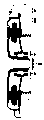
Fig. 4 and Fig. 5 are two kinds of exemplary graphs on the guide rail 6 that elevator machinery 1 of the present invention is placed lift well 51.
In Fig. 4, elevator machinery is contained in the top of guide rail 6 in mode shown in Figure 1.Guide rail 6 can be a cage guide, also can be the balance block guide block.One of elevator cable wire 5 terminates to point 53 places on lift well 51 tops 52, the elevator cable wire is walked around the hauling block 4 of upwards walking around elevator machinery 1 behind the deflection sheave 56 below the escalator 54 with this as the starting point, and then walk around point 58 places that return back up to behind the deflection sheave of balance block 55 on the vertical shaft top downwards, the other end of elevator cable wire promptly is fixed on this aspect.
Fig. 5 represents another kind of method, and wherein elevator machinery 1 installs to the lower end of the guide rail 6 in the lift well 51.One of elevator cable wire 5 terminates to point 53 places at lift well 51 tops 52, this cable wire is walked around the deflection sheave 59 of upwards walking around vertical shaft 51 tops behind the deflection sheave 56 below the escalator 54 with this as the starting point downwards, walks around the hauling block 4 of the elevator machinery 1 that is contained in the guide rail lower end then again downwards.From hauling block 4, cable wire is upwards walked around the deflection sheave 57 of walking around balance block 55 behind another deflection sheave 60 downwards, returns back up to point 58 places of upper ends of elevator shafts again, and the other end of elevator cable wire promptly is fixed on this aspect.
Fig. 6 and Fig. 7 are illustrated in the shock attenuation unit of using in the elevator machinery of the present invention, and this elevator machinery installs on the guide rail 6 with auxiliary stand 64.
The another kind installation method of shock absorber is that each shock absorber is placed between two cup-shape members.The diameter of last cup is a bit larger tham following glass, thereby partly overlaps the cup of staying.If shock absorber damages, the edge of cup can connect mutually, thereby prevents that elevator machinery from deviating from from auxiliary stand.
Those skilled in the art that scholar obviously as can be known, all embodiment of the present invention are not limited to above-mentioned example, but can make change to these examples within the scope of the invention.
Claims (11)
1, be used for along the elevator machinery (1) of the mobile elevator (54) of guide rail (6), described elevator machinery comprises an elevator motor (2) at least and drives the hauling block (4) of elevator cable wire (5); Described elevator motor (2) comprises that a stator (9), a rotor (8) and a motor reel (7) and at least one are positioned at the bearing (10) between rotor (8) and the stator (9), described stator (9) and rotor (8) be dish-shaped and or described elevator motor described motor reel axially on have a flat structure, it is characterized in that this elevator machinery (1) is contained on vertical side of one of guide rail (6) of elevator (54) or balance block (55).
By the described elevator machinery of claim 1 (1), it is characterized in that 2, guide rail (6) is as the framing member of elevator machinery (1).
3,, it is characterized in that the roll center of vertical power by bearing (10) that elevator cable wire (5) acts on the hauling block (6) passes on the guide rail (6) by claim 1 or 2 described elevator machineries (1).
4, by the described elevator machinery of claim 1 (1), it is characterized in that between elevator machinery (1) and guide rail (6) strut member (34) being arranged, described strut member (34) supports elevator machinery (1).
5, by the described elevator machinery of claim 4 (1), it is characterized in that, support the centre of support (37) of the strut member (34) of elevator machinery (1) and on vertical, align with the roll center of bearing (10).
6, by the described elevator machinery of claim 1 (1), it is characterized in that having a vibration-damped component (61,62,63) between elevator machinery (1) and the guide rail (6) at least.
7, by the described elevator machinery of claim 6 (1), it is characterized in that this vibration-damped component (61,62,63) is positioned between the stator (9) and guide rail (6) of elevator motor (2).
8, by the described elevator machinery of claim 1 (1), it is characterized in that it has a vibration-damped component (61,62,63) at least between elevator machinery (1) and guide rail (6); And this vibration-damped component (61,62,63) installs on stator (9) and the guide rail (6) by an auxiliary stand (64), and this auxiliary stand (64) installs on the stator (9), and this vibration-damped component (61,62,63) is positioned between this auxiliary stand (64) and the guide rail (6).
9, by the described elevator machinery of claim 8 (1), it is characterized in that this vibration-damped component is divided into a plurality of parts.
10, by the described elevator machinery of claim 9 (1), it is characterized in that, this vibration-damped component is divided into three parts, i.e. first (61), second the (62), the 3rd (63) shock absorber, wherein, at least two shock absorbers (62,63) prevent that elevator machinery (1) from rotating around the longitudinal axis of guide rail (6), and at least two shock absorbers, promptly first (61) and second (62) and/or the first (61) and the 3rd (63) shock absorber prevent that elevator machinery (1) from departing from the direction of guide rail (6) on vertically.
11, by claim 8 or 9 or 10 described elevator machineries (1), it is characterized in that, this auxiliary stand (64) is as the member that improves the stator rigidity, this auxiliary stand its be positioned at axle (71) position central part some place and locate to install on the stator (9) at 2 on the stator limit with connecting element (77).
Applications Claiming Priority (2)
| Application Number | Priority Date | Filing Date | Title |
|---|---|---|---|
| FIFI943043 | 1994-06-23 | ||
| FI943043A FI95689C (en) | 1994-06-23 | 1994-06-23 | Elevator machinery |
Publications (2)
| Publication Number | Publication Date |
|---|---|
| CN1117938A CN1117938A (en) | 1996-03-06 |
| CN1081162C true CN1081162C (en) | 2002-03-20 |
Family
ID=8540995
Family Applications (1)
| Application Number | Title | Priority Date | Filing Date |
|---|---|---|---|
| CN95107080A Expired - Lifetime CN1081162C (en) | 1994-06-23 | 1995-06-22 | Elevator machinery and its installation |
Country Status (15)
| Country | Link |
|---|---|
| EP (2) | EP0688735B1 (en) |
| JP (1) | JP2777340B2 (en) |
| KR (1) | KR100314454B1 (en) |
| CN (1) | CN1081162C (en) |
| AT (1) | ATE188945T1 (en) |
| AU (1) | AU693542B2 (en) |
| BR (1) | BR9502924A (en) |
| CA (1) | CA2152292C (en) |
| DE (2) | DE69514574T2 (en) |
| DK (1) | DK0688735T3 (en) |
| ES (1) | ES2141865T3 (en) |
| FI (1) | FI95689C (en) |
| GR (1) | GR3033252T3 (en) |
| PT (1) | PT688735E (en) |
| RU (1) | RU2139829C1 (en) |
Cited By (1)
| Publication number | Priority date | Publication date | Assignee | Title |
|---|---|---|---|---|
| CN102933483A (en) * | 2010-06-10 | 2013-02-13 | 通力股份公司 | Fixing arrangement for a hoisting machine, and elevator assembly |
Families Citing this family (55)
| Publication number | Priority date | Publication date | Assignee | Title |
|---|---|---|---|---|
| US5899300A (en) * | 1996-12-20 | 1999-05-04 | Otis Elevator Company | Mounting for an elevator traction machine |
| FI109596B (en) * | 1997-01-23 | 2002-09-13 | Kone Corp | Lift and lift drive machinery |
| US5931265A (en) | 1997-03-27 | 1999-08-03 | Otis Elevator Company | Rope climbing elevator |
| DE19720479A1 (en) * | 1997-05-16 | 1998-11-19 | Baumueller Nuernberg Gmbh | Lifting device, in particular elevator, with an electric motor and use of the electric motor |
| DE59803888D1 (en) * | 1997-10-01 | 2002-05-23 | Wittur Ag | PRE-ASSEMBLED ELEVATOR SHAFT |
| ES2399413T5 (en) * | 1998-02-26 | 2022-06-07 | Otis Elevator Co | Traction elevator system using a flat flexible cable |
| US6138799A (en) * | 1998-09-30 | 2000-10-31 | Otis Elevator Company | Belt-climbing elevator having drive in counterweight |
| WO1999043600A1 (en) * | 1998-02-26 | 1999-09-02 | Otis Elevator Company | Elevator system having drive motor located at the bottom portion of the hoistway |
| US7874404B1 (en) | 1998-09-29 | 2011-01-25 | Otis Elevator Company | Elevator system having drive motor located between elevator car and hoistway sidewall |
| US6397974B1 (en) | 1998-10-09 | 2002-06-04 | Otis Elevator Company | Traction elevator system using flexible, flat rope and a permanent magnet machine |
| EP1056675B1 (en) * | 1998-02-26 | 2006-09-13 | Otis Elevator Company | Elevator system having drive motor located between elevator car and hoistway sidewall |
| ES2502843T3 (en) * | 1998-02-26 | 2014-10-06 | Otis Elevator Company | Elevator system that has the drive motor located at the bottom of the elevator shaft |
| US6860367B1 (en) | 1998-09-29 | 2005-03-01 | Otis Elevator Company | Elevator system having drive motor located below the elevator car |
| WO1999043599A1 (en) * | 1998-02-26 | 1999-09-02 | Otis Elevator Company | Drum drive elevator using flat belt |
| DE69914577C5 (en) * | 1998-02-26 | 2014-11-20 | Otis Elevator Co. | DISC DRIVING SYSTEM WITH FLEXIBLE FLAT ROPE AND PERMANENT MAGNETIC DRIVE |
| US7299896B1 (en) | 1998-09-29 | 2007-11-27 | Otis Elevator Company | Elevator system having drive motor located adjacent to hoistway door |
| MY121775A (en) | 1998-04-28 | 2006-02-28 | Toshiba Kk | Traction type elevator apparatus |
| FI981887A (en) * | 1998-09-04 | 2000-03-05 | Kone Corp | An elevator arrangement for setting the output torque of an elevator motor |
| FI981987A0 (en) * | 1998-09-15 | 1998-09-15 | Kone Corp | Lift arrangement |
| US6305499B1 (en) | 1998-09-30 | 2001-10-23 | Otis Elevator Company | Drum drive elevator using flat belt |
| US6039152A (en) * | 1998-10-30 | 2000-03-21 | Otis Elevator Company | Elevator system with controller located under elevator landing |
| US6848543B2 (en) | 1998-10-30 | 2005-02-01 | Otis Elevator Company | Single wall interface traction elevator |
| US6478117B2 (en) | 1998-10-30 | 2002-11-12 | Otis Elevator Company | Elevator system having governor positioned under controller in hoistway at top floor level |
| US6085874A (en) * | 1998-12-22 | 2000-07-11 | Otis Elevator Company | Rail-climbing elevator counterweight having flat machines |
| US6202793B1 (en) | 1998-12-22 | 2001-03-20 | Richard N. Fargo | Elevator machine with counter-rotating rotors |
| US7246688B2 (en) | 1998-12-23 | 2007-07-24 | Otis Elevator Company | Elevator door system |
| EP1081086B1 (en) * | 1999-08-19 | 2005-10-12 | Inventio Ag | Liftarrangement with a drive unit positioned in the liftshaft |
| DE50011320D1 (en) | 1999-08-19 | 2006-02-23 | Inventio Ag | Elevator installation with a drive unit arranged in an elevator shaft |
| FI106192B (en) | 1999-09-16 | 2000-12-15 | Kone Corp | Lifting machinery for a lift |
| EP1378478B1 (en) * | 1999-12-06 | 2006-08-30 | Mitsubishi Denki Kabushiki Kaisha | Elevator apparatus |
| DE19963286B4 (en) * | 1999-12-27 | 2005-06-23 | Aufzugfabrik Wilhelm Nunn Gmbh & Co. | elevator |
| DE19963297B4 (en) * | 1999-12-27 | 2005-02-24 | Aufzugfabrik Wilhelm Nunn Gmbh & Co. | elevator |
| JP3509727B2 (en) * | 2000-09-19 | 2004-03-22 | 三菱電機株式会社 | Elevator equipment |
| US7178636B2 (en) | 2003-03-25 | 2007-02-20 | Mitsubishi Denki Kabushiki Kaisha | Elevator system |
| US6672013B1 (en) | 2000-11-02 | 2004-01-06 | Otis Elevator Company | Method of installing elevator rails |
| DE60043829D1 (en) * | 2000-12-11 | 2010-03-25 | Mitsubishi Electric Corp | LIFTING EQUIPMENT |
| JP2002284486A (en) * | 2001-03-22 | 2002-10-03 | Sanyo Kogyo Kk | Hoist gear |
| JP4772986B2 (en) * | 2001-06-07 | 2011-09-14 | 三菱電機株式会社 | Elevator main rope locking device |
| JP2003104666A (en) * | 2001-09-28 | 2003-04-09 | Meidensha Corp | Hoisting machine and elevator device |
| DE10205170B4 (en) * | 2002-02-07 | 2005-07-21 | Wittur Ag | Traction elevator |
| KR100441043B1 (en) * | 2002-08-28 | 2004-07-19 | 현대엘리베이터주식회사 | Slimming type traction machine |
| IL180964A (en) * | 2002-09-05 | 2010-11-30 | Inventio Ag | Drive engine for a lift installation and method of mounting a drive engine |
| DE20318523U1 (en) * | 2003-11-29 | 2005-05-19 | Swiss-Traction Ag | Gearless compact drive system with external rotor for lifts has stator anchored on first bearing end plate to support bearing of rotor of motor having permanent magnets on inner circumference and cable grooves on outer circumference |
| EP1790609B1 (en) * | 2004-07-29 | 2014-03-05 | Mitsubishi Denki Kabushiki Kaisha | Hoist for elevator |
| JP4529645B2 (en) * | 2004-11-08 | 2010-08-25 | 株式会社日立製作所 | Machine room-less elevator device |
| DE102005002607A1 (en) * | 2005-01-20 | 2006-08-10 | System Antriebstechnik Dresden Gmbh | Elevator, with a cabin riding between guide rails, has the machine and emergency brake in a cube structure mounted at the top of the shaft with an angle carrier at the shaft wall and roof |
| JP4770303B2 (en) * | 2005-07-12 | 2011-09-14 | 三菱電機株式会社 | Elevator equipment |
| KR100703461B1 (en) * | 2006-03-03 | 2007-04-03 | 미쓰비시덴키 가부시키가이샤 | Winch for elevator |
| JP4511606B2 (en) * | 2008-03-06 | 2010-07-28 | 東芝エレベータ株式会社 | Elevator equipment |
| JP2008303070A (en) * | 2008-08-22 | 2008-12-18 | Mitsubishi Electric Corp | Elevator apparatus |
| JP5955280B2 (en) * | 2013-07-09 | 2016-07-20 | 株式会社日立ビルシステム | Lifting method for heavy elevators |
| EP3283425B1 (en) | 2015-04-17 | 2020-08-19 | Otis Elevator Company | Elevator system |
| JP6587586B2 (en) * | 2016-07-05 | 2019-10-09 | 株式会社日立製作所 | Elevator hoisting machine |
| CN108551247B (en) * | 2018-06-06 | 2023-09-22 | 上海吉亿电机有限公司 | Double-support double-stator permanent magnet synchronous traction machine |
| WO2021124389A1 (en) * | 2019-12-16 | 2021-06-24 | 株式会社日立製作所 | Hoist and elevator |
Citations (3)
| Publication number | Priority date | Publication date | Assignee | Title |
|---|---|---|---|---|
| US2088690A (en) * | 1935-08-14 | 1937-08-03 | Inclinator Company Of America | Elevator |
| US4664320A (en) * | 1982-04-19 | 1987-05-12 | Bert Steffens | Apparatus for separating the components of cellulose sanitary articles |
| US5018603A (en) * | 1988-08-26 | 1991-05-28 | Mitsubishi Denki Kabushiki Kaisha | Elevator hoist apparatus |
Family Cites Families (2)
| Publication number | Priority date | Publication date | Assignee | Title |
|---|---|---|---|---|
| US4664230A (en) * | 1984-03-23 | 1987-05-12 | Olsen Lawrence O | Elevator |
| JPH0450297Y2 (en) * | 1987-01-28 | 1992-11-26 | Mitsubishi Electric Corp |
-
1994
- 1994-06-23 FI FI943043A patent/FI95689C/en not_active IP Right Cessation
-
1995
- 1995-06-13 DE DE69514574T patent/DE69514574T2/en not_active Expired - Lifetime
- 1995-06-13 PT PT95109094T patent/PT688735E/en unknown
- 1995-06-13 EP EP95109094A patent/EP0688735B1/en not_active Expired - Lifetime
- 1995-06-13 DK DK95109094T patent/DK0688735T3/en active
- 1995-06-13 DE DE0688735T patent/DE688735T1/en active Pending
- 1995-06-13 ES ES95109094T patent/ES2141865T3/en not_active Expired - Lifetime
- 1995-06-13 AT AT95109094T patent/ATE188945T1/en active
- 1995-06-13 EP EP98119942A patent/EP0891939A1/en not_active Withdrawn
- 1995-06-19 AU AU21735/95A patent/AU693542B2/en not_active Expired
- 1995-06-20 JP JP7152810A patent/JP2777340B2/en not_active Expired - Fee Related
- 1995-06-21 CA CA002152292A patent/CA2152292C/en not_active Expired - Lifetime
- 1995-06-22 CN CN95107080A patent/CN1081162C/en not_active Expired - Lifetime
- 1995-06-22 RU RU95110779A patent/RU2139829C1/en active
- 1995-06-23 KR KR1019950017059A patent/KR100314454B1/en not_active IP Right Cessation
- 1995-06-23 BR BR9502924A patent/BR9502924A/en not_active IP Right Cessation
-
2000
- 2000-04-17 GR GR20000400935T patent/GR3033252T3/en unknown
Patent Citations (3)
| Publication number | Priority date | Publication date | Assignee | Title |
|---|---|---|---|---|
| US2088690A (en) * | 1935-08-14 | 1937-08-03 | Inclinator Company Of America | Elevator |
| US4664320A (en) * | 1982-04-19 | 1987-05-12 | Bert Steffens | Apparatus for separating the components of cellulose sanitary articles |
| US5018603A (en) * | 1988-08-26 | 1991-05-28 | Mitsubishi Denki Kabushiki Kaisha | Elevator hoist apparatus |
Cited By (3)
| Publication number | Priority date | Publication date | Assignee | Title |
|---|---|---|---|---|
| CN102933483A (en) * | 2010-06-10 | 2013-02-13 | 通力股份公司 | Fixing arrangement for a hoisting machine, and elevator assembly |
| CN102933483B (en) * | 2010-06-10 | 2016-02-10 | 通力股份公司 | For anchor fitting and the elevator assemblies of gig |
| US9309092B2 (en) | 2010-06-10 | 2016-04-12 | Kone Corporation | Fixing arrangement for a hoisting machine, and elevator assembly |
Also Published As
| Publication number | Publication date |
|---|---|
| CA2152292C (en) | 2004-08-31 |
| DE69514574D1 (en) | 2000-02-24 |
| GR3033252T3 (en) | 2000-09-29 |
| DE688735T1 (en) | 1998-04-09 |
| FI943043A0 (en) | 1994-06-23 |
| DK0688735T3 (en) | 2000-06-19 |
| EP0688735A2 (en) | 1995-12-27 |
| PT688735E (en) | 2000-05-31 |
| CA2152292A1 (en) | 1995-12-24 |
| ATE188945T1 (en) | 2000-02-15 |
| AU2173595A (en) | 1996-01-11 |
| RU95110779A (en) | 1997-05-20 |
| FI95689C (en) | 1996-03-11 |
| DE69514574T2 (en) | 2000-09-07 |
| KR960000750A (en) | 1996-01-25 |
| JPH0840676A (en) | 1996-02-13 |
| ES2141865T3 (en) | 2000-04-01 |
| EP0891939A1 (en) | 1999-01-20 |
| JP2777340B2 (en) | 1998-07-16 |
| EP0688735A3 (en) | 1996-05-08 |
| RU2139829C1 (en) | 1999-10-20 |
| EP0688735B1 (en) | 2000-01-19 |
| CN1117938A (en) | 1996-03-06 |
| AU693542B2 (en) | 1998-07-02 |
| BR9502924A (en) | 1996-01-30 |
| KR100314454B1 (en) | 2002-11-22 |
| FI95689B (en) | 1995-11-30 |
Similar Documents
| Publication | Publication Date | Title |
|---|---|---|
| CN1081162C (en) | Elevator machinery and its installation | |
| US5899301A (en) | Elevator machinery mounted on a guide rail and its installation | |
| RU2150423C1 (en) | Device for attachment of hoist drive to building | |
| JP3168161B2 (en) | Traction sheave elevator | |
| JP4157631B2 (en) | Elevator device | |
| CN1042318C (en) | Elevator machinery | |
| HU220752B1 (en) | Elevator built from uniformed units | |
| JP2000153975A (en) | Elevator with tow sheave | |
| EP1333000A1 (en) | A machine-roomless traction sheave elevator | |
| CN1099994C (en) | Rope traction elevator | |
| GB2352221A (en) | Elevator system | |
| FI106192B (en) | Lifting machinery for a lift | |
| JP4216252B2 (en) | Elevator equipment | |
| JP3700412B2 (en) | Traction elevator | |
| JP4723241B2 (en) | Elevator manufacturing method and elevator delivery system | |
| CN1266020C (en) | Friction-driven hoist | |
| FI93939B (en) | Driving pulley lift of the overlift type | |
| CN219194133U (en) | Elevator traction device and elevator | |
| CN100540442C (en) | The drive system that is used for the actuating device space in the vertical shaft cross-sectional plane | |
| JP2001039655A (en) | Elevator hoist installation structure | |
| CN111362101A (en) | Novel household screw platform elevator | |
| JPH0867461A (en) | Linear motor elevator | |
| JPH09295777A (en) | Linear motor elevator |
Legal Events
| Date | Code | Title | Description |
|---|---|---|---|
| C06 | Publication | ||
| PB01 | Publication | ||
| C10 | Entry into substantive examination | ||
| SE01 | Entry into force of request for substantive examination | ||
| C14 | Grant of patent or utility model | ||
| GR01 | Patent grant | ||
| C17 | Cessation of patent right | ||
| CX01 | Expiry of patent term |
Expiration termination date: 20150622 Granted publication date: 20020320 |