JP4529645B2 - Machine room-less elevator device - Google Patents
Machine room-less elevator device Download PDFInfo
- Publication number
- JP4529645B2 JP4529645B2 JP2004323429A JP2004323429A JP4529645B2 JP 4529645 B2 JP4529645 B2 JP 4529645B2 JP 2004323429 A JP2004323429 A JP 2004323429A JP 2004323429 A JP2004323429 A JP 2004323429A JP 4529645 B2 JP4529645 B2 JP 4529645B2
- Authority
- JP
- Japan
- Prior art keywords
- synchronous motor
- pulse generator
- thin synchronous
- car
- sheave
- Prior art date
- Legal status (The legal status is an assumption and is not a legal conclusion. Google has not performed a legal analysis and makes no representation as to the accuracy of the status listed.)
- Expired - Fee Related
Links
Images


Description
本発明は機械室レスエレベータ装置に係り、特に、昇降路内または狭隘な機械室に設置された薄型同期電動機により、乗りかごを昇降駆動させる機械室レスエレベータ装置に関するものである。 The present invention relates to a machine room-less elevator apparatus, and more particularly to a machine room-less elevator apparatus that drives a car up and down by a thin synchronous motor installed in a hoistway or a narrow machine room.
エレベータの駆動用電動機としては、従来より、直流電動機や誘導電動機が用いられている。電動機の出力軸にはパルス発生器が直結され、電動機の回転に伴ってパルス発生器から発生するパルスによって電動機の速度や乗りかごの位置を算出し、その算出結果に基づいてエレベータ装置を制御している。また、実用新案第1846853号のように、パルス発生器に連結されたローラを電動機の回転部に当接させ、該ローラをフリクション駆動で回転させることによりパルス発生器からパルスを発生させ、そのパルスに基づいてエレベータ装置を制御する方法も提案されている。 Conventionally, DC motors and induction motors have been used as elevator drive motors. A pulse generator is directly connected to the output shaft of the motor, and the speed of the motor and the position of the car are calculated by pulses generated from the pulse generator as the motor rotates, and the elevator system is controlled based on the calculation results. ing. Further, as in Utility Model No. 1846853, a roller connected to a pulse generator is brought into contact with a rotating portion of an electric motor, and the roller is rotated by friction drive to generate a pulse from the pulse generator. A method of controlling the elevator apparatus based on the above has also been proposed.
また、ハイブリッドカーや一部産業界では、省エネルギの観点からシステムの駆動用電動機に永久磁石を用いた同期電動機が用いられ始め、この傾向はエレベータにも波及し始めている。このような同期電動機の出力軸にはパルス発生器が直結されている。そして、パルス発生器からのパルスに基づいて、電動機の速度や乗りかごの位置の他、電動機の磁極位置も検出できるようにしている。 In hybrid cars and some industries, synchronous motors using permanent magnets have started to be used as system drive motors from the viewpoint of energy saving, and this trend has begun to spread to elevators. A pulse generator is directly connected to the output shaft of such a synchronous motor. Based on the pulse from the pulse generator, the magnetic pole position of the motor can be detected in addition to the speed of the motor and the position of the car.
また近年、日影規制、つまり屋上機械室高さを削減する観点から、昇降路内のすき間空間を巻上機設置スペースとしたり、昇降路のピット床面積と同程度、あるいはそれ以下の狭隘なスペースをミニ機械室とするために、エレベータの駆動装置を軸方向に薄型化して設置する、いわゆる省機械室エレベータが注目を集め始めている。 In recent years, in order to reduce the height of the rooftop machine room, the clearance space in the hoistway is used as a hoisting machine installation space, or it is narrower than the pit floor area of the hoistway. In order to make the space into a mini-machine room, so-called machine-saving machine room elevators, in which elevator drive devices are thinned and installed in the axial direction, have begun to attract attention.
この同期電動機による省エネルギなシステム駆動と省機械室に代表される省空間システムという2つの新しい流れを融合した省機械室エレベータでは、電動機自体を回転子の軸方向に極薄化することが限られた設置空間への配置・実装の観点から必須要項である。さらに、この駆動電動機自体の薄型化以外にも、同期電動機の制御に必要な磁極位置情報を検出するための磁極位置センサなど制御用機器センサについても軸方向の薄型化・小型化を図る必要がある。 In an energy-saving machine room elevator that combines the two new trends of energy-saving system drive with a synchronous motor and a space-saving system represented by a machine-saving room, it is limited to make the motor itself extremely thin in the axial direction of the rotor. It is an essential requirement from the viewpoint of placement and mounting in the designated installation space. In addition to making the drive motor itself thinner, control device sensors such as a magnetic pole position sensor for detecting magnetic pole position information necessary for controlling the synchronous motor need to be made thinner and smaller in the axial direction. is there.
なお、前者である電動機本体の薄型化システムについては特許第2593288号に円盤状の回転子を有するエレベータシステムが提案され、後者のパルス発生器の薄型化については、一般の電動機応用分野として、平成10年電気学会全国大会No.883等にあるように同期電動機の磁極位置をソフトウェアで演算・推定し、センサ自体を省略する試みが提案されている。 Regarding the former motor body thinning system, Japanese Patent No. 2593288 proposes an elevator system having a disk-like rotor, and the latter pulse generator thinning is a general application field of motors. There has been proposed an attempt to calculate and estimate the magnetic pole position of a synchronous motor with software and omit the sensor itself as described in the 10th Annual Conference of the Institute of Electrical Engineers of Japan No. 883 and the like.
しかしながら上記従来技術のうち、前者のエレベータシステムでは厚さが薄い電動機のシステムについての提案が主であり、同期電動機固有の磁極位置センサを含めた巻上機としてのシステム薄型化についてはあまり触れられていない。 However, among the above prior arts, the former elevator system mainly proposes a motor system with a small thickness, and much attention has been paid to the thinning of the system as a hoisting machine including a magnetic pole position sensor unique to a synchronous motor. Not.
また、後者の磁極位置センサレスシステムでは、計測のための回転に関する制約があまり課されていないことを前提にしており、エレベータの様に乗りかごが中間階ゾーンにいる間に計測運転が完了せねばならないような乗りかご位置の制約が存在する用途には適用上の問題も存在する。 In the latter magnetic pole position sensorless system, it is assumed that there are not many restrictions on rotation for measurement, and the measurement operation must be completed while the car is in the middle floor zone like an elevator. There are also application problems in applications where there are restrictions on the position of the car that cannot be avoided.
本発明の目的は、乗りかごの駆動用電動機として薄型同期電動機を用いた場合に、その薄型同期電動機を含む巻上機を薄型化することのできる機械室レスエレベータ装置を提供することにある。 An object of the present invention is to provide a machine room-less elevator device capable of reducing the thickness of a hoisting machine including a thin synchronous motor when a thin synchronous motor is used as a motor for driving a car.
上記目的を達成するため、本発明は、昇降路内に昇降自在に設けられた乗りかごと、前記昇降路内に設置された薄型同期電動機と、該薄型同期電動機の回転に伴ってパルスを発生するパルス発生器と、を有し、前記薄型同期電動機の回転駆動力によって前記乗りかごを前記昇降路内で昇降させるとともに、前記パルス発生器からのパルスに基づいて前記乗りかごの昇降を制御するエレベータ装置において、乗りかご又は釣り合い重りの走行案内用のレールに固定された前記薄型同期電動機と、前記薄型同期電動機の出力軸に連結され、外周の周方向に沿って溝が形成され、該溝に前記乗りかごと釣り合い重りとをつり下げるロープが掛けられる綱車と、前記鋼車のロープが掛けられる径よりも大きい径とされた外周面にブレーキが押圧されて制動されるブレーキドラムと、前記外周面において前記ブレーキが押圧される面を共用するようにかつ頂上部から周方向に引き下げた位置に当接され、前記綱車の径よりも小さくされた摩擦駆動輪と、前記摩擦駆動輪の回転軸に連結され、回転に伴ってパルスを発生し、該パルス列より前記薄型同期電動機の磁極位置,電動機速度、および乗りかご位置が算出されるパルス発生器と、前記パルス発生器により算出される前記磁極位置の情報から可変周波数,可変位相,可変電圧の電流を前記薄型同期電動機に流すインバータと、を備え、前記綱車とブレーキドラムとが前記薄型同期電動機によって回転駆動される回転構造体とされ、前記摩擦駆動輪と前記パルス発生器は、前記薄型同期電動機が固定された前記レール面側から前記薄型同期電動機、前記ブレーキドラム、前記綱車の厚み方向の範囲に収納され、昇降路内のすき間空間に前記薄型同期電動機、前記パルス発生器を含めた巻上機全体が格納された機械室レスエレベータとするものである。 In order to achieve the above object, the present invention provides a car that is movably installed in a hoistway, a thin synchronous motor installed in the hoistway, and a pulse generated as the thin synchronous motor rotates. A pulse generator that moves the car up and down in the hoistway by the rotational driving force of the thin synchronous motor, and controls the raising and lowering of the car based on the pulse from the pulse generator In the elevator apparatus, the thin synchronous motor fixed to a traveling guide rail of a car or a counterweight, and a groove is formed along the circumferential direction of the outer periphery, and is connected to the output shaft of the thin synchronous motor. and the car and the counterweight and the fishing lowering sheave rope is applied, the steel car brake rope outer peripheral surface that is larger in diameter than that exerted is pressed by A brake drum that is moving, wherein the outer peripheral surface brake is brought into contact with a position lowered from and top portion so as to share a surface to be pressed in the circumferential direction, friction drive, which is smaller than the diameter of the sheave A pulse generator coupled to a wheel and a rotation shaft of the friction drive wheel, generating a pulse with rotation, and calculating a magnetic pole position, a motor speed, and a car position of the thin synchronous motor from the pulse train; An inverter for passing a current of variable frequency, variable phase, and variable voltage to the thin synchronous motor from the magnetic pole position information calculated by the pulse generator, and the sheave and the brake drum are driven by the thin synchronous motor. The friction drive wheel and the pulse generator are configured to be rotationally driven. The thin synchronous motor is connected to the thin synchronous motor from the rail surface side to which the thin synchronous motor is fixed. Machine, the brake drum, is accommodated in the range of the thickness direction of the sheave, said the clearance space thin synchronous motor in the hoistway, and a machine room-less elevator entire pulse generator including the hoisting machine is stored To do .
また、上記のものにおいて、前記パルス発生器は、前記薄型同期電動機に固定されていることが望ましい。
Moreover, in the above, it is desirable that the pulse generator is fixed to the thin synchronous motor .
以上述べたように、本発明によれば、電動機ばかりだけでなく、電動機を制御するための、摩擦駆動輪やパルス発生器からなるセンサを含めた巻上機全体を極限まで薄型化でき、限られた設置空間に大容量の駆動装置を格納できるようになる。その結果、速度の低いエレベータから速度の高いエレベータまで、シリーズ化された機械室レスエレベータを実現することが可能となる。 As described above, according to the present invention, not only the electric motor but also the entire hoisting machine including the sensor including the friction drive wheel and the pulse generator for controlling the electric motor can be thinned to the limit. A large-capacity drive device can be stored in the installed space. As a result, a series of machine room-less elevators from a low-speed elevator to a high-speed elevator can be realized.
以下、本発明の実施の形態を図面に従って説明する。 Hereinafter, embodiments of the present invention will be described with reference to the drawings.
図1は本発明に係る機械室レスエレベータ装置の全体構成を示している。なお、ここでは、エレベータ駆動用電動機として、回転軸方向に薄型扁平な同期電動機が用いられ、これに主回路としてPWMコンバータ・PWMインバータが接続された例を示している。 FIG. 1 shows the overall configuration of a machine room-less elevator apparatus according to the present invention. Here, an example in which a thin and flat synchronous motor in the direction of the rotation axis is used as an elevator driving motor, and a PWM converter and a PWM inverter are connected as a main circuit to this is shown.
図1において、交流電源1は、IGBT(絶縁型ゲートバイポーラトランジスタ)等の自己消弧素子を用いて構成したPWMコンバータ2に接続され、さらにPWMコンバータ2はPWMインバータ3に接続されている。PWMインバータ3にはエレベータを駆動するための薄型同期電動機4が接続され、この薄型同期電動機4の出力軸にはブレーキドラム5と綱車7が固定されている。ブレーキドラム5の外周面側にはブレーキ6が設けられ、ブレーキドラム5はブレーキ6に挟まれて制動される。綱車7にはロープ8が掛け回されており、このロープ8の一端側には乗りかご9が他端側には釣り合い重り10が取り付けられている。ここでは、ローピングは乗りかご9と釣り合い重り10が1:1に接続されている例を示しているが、2:1ローピングや乗りかご9の下をロープ8がくぐるアンダースラング方式であってもよい。なお、ブレーキドラム5と綱車7が回転構造体に相当している。
In FIG. 1, an
綱車7の外周面には、綱車7よりも径の小さい摩擦駆動輪11が当接して設けられ、さらに摩擦駆動輪11はパルス発生器12に連結されている。そして綱車7が回転すると、摩擦により摩擦駆動輪11が回転して、綱車7の回転がパルス発生器12に伝えられる。パルス発生器12は綱車7の回転に伴ってパルスを発生し、このパルス列は伝送線13を経由して制御装置14に入力される。
A friction drive wheel 11 having a diameter smaller than that of the
入力されたパルス列は、かご位置検出部141、速度検出部142および回転子位置検出部143に取り込まれ、それぞれ乗りかご位置、速度、回転子位置に変換処理される。すなわち、かご位置検出部141では一定時間ごとにパルスを累積して乗りかご9の位置を算出し、速度検出部142はパルスの幅の逆数などから綱車の回転速度ωを算出し、回転子位置検出部143は基準信号入力とパルスの積算からパルス発生器の回転角と等価な同期電動機回転子の位置を算出する。なお、かご位置の検出に関しては、かごの移動に伴って、かごの昇降路内の絶対位置を直接的に検出する他のセンサを別置すれば、かご位置検出のためのパルス発生器信号の入力とかご位置検出部141も不要になる。さらに、電動機の電流情報などから電動機の回転速度を推定すれば、電動機回転速度検出のためのパルス発生器信号の入力と速度検出部142も不要になる。
The input pulse train is taken into the
制御装置14内には、かご位置検出部141、速度検出部142、回転子位置検出部143以外に、速度指令発生部144、かご呼び検出部145、速度制御部146、電流制御部147および搬送波発生部148が設けられている。速度指令発生部144では、かご呼び検出部145の出力である停止予定階の位置データからかご位置検出部141の出力データを減算することによって現在の乗りかご位置から停止予定階までの残距離を算出し、更にこの残距離と所定減速度との積の平方根をとることによって減速速度指令ω*を算出する。速度制御部146では速度指令ω*に検出した電動機速度ωを一致させるように負帰還制御が行われ、ベクトル演算の結果、インバータのためのPWM信号の材料であるトルク指令τ*が出力される。このとき、電流制御部147へは駆動電動機が直流電動機や誘導電動機の場合にはこれ以上の情報は不要であるが、省エネルギと電動機の薄型化を指向して同期電動機を使用した機械室レスエレベータの場合には、電動機の回転子の磁極位置情報が制御上必要であり、この磁極位置情報も電流制御部147に取り込まれる。電流制御部147ではPWM信号作成のための変調波ei*を発生し、インバータ用PWMパルス作成部15に入力する。
In addition to the
一方、搬送波発生部148はインバータのスイッチング周波数を決定するための搬送波eti* を発生し、変調波ei*とともにインバータ用PWMパルス作成部15に入力する。これにより、インバータ用PWMパルス作成部15は同期電動機の回転子位置に応じ、乗りかごが所定の速度となるような可変周波、可変位相、可変電圧の出力が得られるようなPWM制御信号をPWMインバータ3に与える。なお、ここでは本発明と直接関係しないので省略したが、PWMコンバータ2は出力コンデンサの電圧が所定値となるようにコンデンサ電圧の負帰還制御がなされ、同様にPWM制御される。
On the other hand, the carrier
このように、同期電動機では、電動機の回転に伴って変化する回転子の位置を把握することが、電動機の速度検出や乗りかごの位置検出と同等以上に制御上重要である。 As described above, in the synchronous motor, grasping the position of the rotor that changes with the rotation of the motor is as important in control as the speed detection of the motor and the position detection of the car.
(実施の形態1)
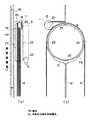
次に、同期電動機の回転子4、ブレーキドラム5、ブレーキ6、綱車7、摩擦駆動輪11、パルス発生器12と昇降路空間との関係について説明する。図2は本発明の実施の形態1を示しており、(a)は巻上機付近の側面図、(b)は正面図である。
(Embodiment 1)
Next, the relationship among the rotor 4, the
図2に示すように、昇降路壁面17には固定用金具18が取り付けられ、この固定用金具18に薄型同期電動機41が固定されている。固定用金具18は電動機取り付け専用の金具でも良いし、乗りかごや釣り合い重りの走行案内用のレールで代用しても良い。図2では薄型同期電動機41は固定子のみが示されている。図には示してないが、固定子の内側には回転子が設けられている。そして、前記回転子に出力軸19が連結され、この出力軸19には、昇降路壁面17から離れる方向に沿って、ブレーキドラム5、綱車7が固定されている。
As shown in FIG. 2, a fixing
ブレーキドラム5の外周面にはブレーキ6が配置されている。このブレーキ6はブレーキドラム5の外周面を押圧することによって、エレベータ停止時の保持力や非常停止時の制動力を発生する。また、綱車7の外面には周方向に沿って複数の溝が形成され、これらの溝に乗りかごと釣り合い重りをつるべ式につり下げるロープ8が複数本掛けられている。綱車7の一側には、図に示すようにロープ8が掛けられた面よりも一段径方向に高い鍔部7Aが形成され、この鍔部7Aの周縁端部に摩擦駆動輪11が当接しており、この摩擦駆動輪11は綱車7の回転に伴って回転する。なお、摩擦駆動輪11の直径は鍔部7Aの直径よりも小さく設定されている。
A
摩擦駆動輪11の回転軸はパルス発生器12に連結されており、パルス発生器12は摩擦駆動輪11の回転に伴ってパルスを発生する。パルス発生器12はブレーキドラム5に並列に配置され、また取付金具20を介して薄型同期電動機41に取り付けられている。
The rotation shaft of the friction drive wheel 11 is connected to a
上記構成によれば、薄型同期電動機41の回転子位置、つまり磁極の位置を綱車7の回転を介して間接的に測定することができ、磁極位置に見合った可変周波数、可変位相、可変電圧の電流をインバータから薄型同期電動機41に流すことができる。その結果、高効率ゆえに小型、薄型で昇降路内に実装可能な同期電動機41をエレベータ駆動用電動機として制御できるようになる。
According to the above configuration, the rotor position of the thin
そして特に注目すべきは、磁極位置検出用のパルス発生器12が、従来のように電動機の出力軸の延長線上ではなく、ブレーキドラム5に並列に配置されていることである。これにより、摩擦駆動輪11とパルス発生器12は、エレベータを駆動するための必須装置である薄型同期電動機41とブレーキドラム5と綱車7よりなる巻上機の厚み方向の範囲内(図2(a)において、薄型同期電動機41の左端面から綱車7の右端面の間)に収まり、昇降路壁面17側や、乗りかごや釣り合い重りの昇降する側には全くはみ出さない。
特に、巻上機を昇降路内に設置するには、パルス発生器12が乗りかごや釣り合い重りの昇降する側には全くはみ出さないことが重要な条件であり、本実施の形態では、このような条件を十分に満たすことができる。
It should be particularly noted that the
In particular, in order to install the hoisting machine in the hoistway, it is an important condition that the
また、ロープ8やその接触部からは潤滑用の油が飛散する可能性あり、その油が摩擦駆動輪11に付着するとスリップ現象を起こす恐れがあるが、本実施の形態では綱車7の鍔部7Aに摩擦駆動輪11が当接しているので、万一、潤滑用の油が飛散しても、ロープ8から離れた位置にある摩擦駆動輪11に付着することはなく、摩擦駆動輪11がスリップするのを防ぐことができる。
In addition, there is a possibility that lubricating oil may be scattered from the
また、摩擦駆動輪11は、その直径が鍔部7Aの直径よりも小さく設定されているので、綱車7の回転検出に関する増速効果があり、その結果、一回転あたりに発生するパルス数がそれほど多くない安価な仕様なパルス発生器12を使用できる。
Further, since the friction drive wheel 11 is set to have a diameter smaller than the diameter of the
なお、ブレーキドラム5と綱車7が左右に入れ替わった構造のエレベータ装置の場合は、摩擦駆動輪11が昇降路壁面17側に接近するので取付金具20の長さが短くなり、摩擦駆動輪11の回転に伴って生じるパルス発生器12の振動を抑制できる効果がある。
In the case of an elevator apparatus having a structure in which the
(実施の形態2)
図3は本発明の実施の形態2を示している。本実施の形態では、摩擦駆動輪11の当接先を、綱車7ではなく、ブレーキドラム5としている。すなわち、ブレーキドラム5には鍔部5Aが形成され、この鍔部5Aに摩擦駆動輪11が当接している。
(Embodiment 2)
FIG. 3 shows a second embodiment of the present invention. In the present embodiment, the contact point of the friction drive wheel 11 is not the
ブレーキドラム5は綱車7よりも油などの飛散が少ないので、摩擦駆動輪11への油の付着も少なくなり、摩擦駆動輪11のスリップなど異常現象が発生しにくくなるという効果が期待できる。
Since the
なお、ブレーキドラム5に鍔部5Aを形成しないで、ブレーキドラム5の外周面にそのまま摩擦駆動輪11を当接させるようにしても良い。このようにすると、ブレーキドラム5の加工が容易となる。
The friction drive wheel 11 may be brought into contact with the outer peripheral surface of the
(実施の形態3)
図4は本発明の実施の形態3を示している。本実施の形態では、摩擦駆動輪11の当接先をブレーキドラム5とし、さらに当接位置をブレーキドラム5の頂上部ではなく、ブレーキドラム5の周方向に約45度に引き下げた位置としている。そして、この引き下げた位置でパルス発生器12は薄型同期電動機41の固定子に固定されている。
(Embodiment 3)
FIG. 4 shows a third embodiment of the present invention. In the present embodiment, the contact point of the friction drive wheel 11 is the
このように構成すれば、摩擦駆動輪11やパルス発生器12を含む巻上機全体を小型化できる。すなわち、摩擦駆動輪11やパルス発生器12はブレーキドラム5の周方向に約45度に引き下げた位置にあるので、昇降路壁面に沿った鉛直方向および水平方向への出っ張りを最小化でき、巻上機全体の小型化を図ることが可能となる。
If comprised in this way, the whole winding machine containing the friction drive wheel 11 and the
なお、摩擦駆動輪11やパルス発生器12の自重により押圧して摩擦駆動輪11をブレーキドラム5に当接させる場合、本実施の形態では実施の形態2に比べて押圧力が不足する恐れがある。このような場合は、摩擦駆動輪11をばねなどでブレーキドラム5に押し付けるようにすれば良い。
When the friction drive wheel 11 or the
また、本実施の形態では、ブレーキドラム5には、実施の形態2の場合のように鍔部が設けられておらず、摩擦駆動輪11とブレーキ6がブレーキドラム6の同一の外周面をオーバーラップして共用する形となっている。このようにすれば、ブレーキドラム6の外周面がブレーキ動作時に適度に研磨されるので、ブレーキドラム6外周面の錆などにより生じるパルス発生器12の回転脈動を防止できるという効果がある。
In the present embodiment, the
(実施の形態4)
図5は本発明の実施の形態4を示している。本実施の形態では、電動機として、回転子が外周側に、固定子が内周側にそれぞれ設けられた、いわゆる外転型の薄型同期電動機42が用いられている。また回転子の回転外周面上にはロープ8のための溝が形成され、この回転子の回転外周面は綱車7Bとしての機能を兼ね備えている。そして、この綱車7Bの端部に摩擦駆動輪11が当接している。摩擦駆動輪11は、当接位置が綱車7Bの頂上部ではなく、綱車7Bの周方向に約45度に引き下げた位置となっている。摩擦駆動輪11にはパルス発生器12が連結され、このパルス発生器12は取付金具20を介して固定用金具18に固定されている。
(Embodiment 4)
FIG. 5 shows a fourth embodiment of the present invention. In the present embodiment, a so-called abduction type thin
また、薄型同期電動機42の回転子、つまり綱車7Bにはその周方向4ヶ所に設けられた取付金具23を介してブレーキドラム5が取り付けられている。ブレーキドラム5にはその外周面に対向してブレーキ6が設置されている。
Moreover, the
本実施の形態によれば、薄型同期電動機42の回転子が綱車7Bとして機能し、電動機と綱車を軸方向で重ね合わせた構成となるので、その分、巻上機全体の軸方向の長さが短くなり、巻上機をより一層薄型化することが可能となる。
According to the present embodiment, the rotor of the thin
なお、本実施の形態では、摩擦駆動輪11の綱車7Bへの当接位置を、綱車7Bの周方向に約45度に引き下げた位置としていたが、綱車7Bの頂上部でも良い。ただ、綱車7Bの周方向に約45度に引き下げた位置であれば、実施の形態3の場合と同様に、昇降路壁面に沿った鉛直方向および水平方向への出っ張りを最小化でき、巻上機全体の小型化を図ることが可能となる。 In the present embodiment, the contact position of the friction drive wheel 11 with the sheave 7B is a position that is lowered to about 45 degrees in the circumferential direction of the sheave 7B, but it may be the top of the sheave 7B. However, if the position is lowered to about 45 degrees in the circumferential direction of the sheave 7B, as in the case of the third embodiment, the vertical and horizontal bulges along the hoistway wall surface can be minimized. It is possible to reduce the size of the entire machine.
(実施の形態5)
図6は本発明の実施の形態5を示している。本実施の形態では、摩擦駆動輪11がブレーキドラム5の外周面ではなく内周面に当接している。すなわち、ブレーキドラム5は円筒形状をなしており、その内部には空間が存在しているので、この内部空間に摩擦駆動輪11とパルス発生器12が配置されている。ブレーキ6もブレーキドラム5の内部空間に配置されており、ブレーキ6はブレーキドラム5の内周面を押圧して制動するようになっている。また、パルス発生器12は取付金具20を介して薄型同期電動機41に取り付けられている。
(Embodiment 5)
FIG. 6 shows a fifth embodiment of the present invention. In the present embodiment, the friction drive wheel 11 is in contact with the inner peripheral surface rather than the outer peripheral surface of the
本実施の形態によれば、摩擦駆動輪11とパルス発生器12とを巻上機の内部に隠すことができるために、ゴミや水滴、油等による悪影響を防ぐことができる。すなわち、機械室レスエレベータシステムにおいては、雰囲気の悪い昇降路内に巻上機が露出して設置されるため、ゴミや水滴、油等が摩擦駆動輪11やパルス発生器12に飛散して悪影響を及ぼすことが懸念されるが、摩擦駆動輪11とパルス発生器12とが巻上機の内部に隠されていれば、摩擦駆動輪11やパルス発生器12にゴミや水滴、油等が飛散するのを防ぐことができる。
According to the present embodiment, since the friction drive wheel 11 and the
そして特に、本実施の形態によれば、上記のようにゴミや水滴、油等による悪影響を防ぐことができるため、薄型同期電動機41の回転子の位置を、直結ではなく、粗結合で等価的に検出しているのにもかかわらず、信頼性の高い検出結果を得ることができる。
In particular, according to the present embodiment, since the adverse effects due to dust, water droplets, oil, etc. can be prevented as described above, the position of the rotor of the thin
なお、この方式の場合は、回転むらが発生しないようにブレーキドラム5の内周面を高精度に加工する必要があるが、本実施の形態では、ブレーキドラム面をブレーキドラム5の内周面側としているので、ブレーキドラム5の外周面側は加工する必要が無く、加工の手間は他の実施の形態の場合と殆ど変わらない。
In the case of this method, it is necessary to process the inner peripheral surface of the
1…電源、2…PWMコンバータ、3…PWMインバータ、4…薄型同期電動機、5…ブレーキドラム、5A…鍔部、6…ブレーキ、7,7B…綱車、7A…鍔部、8…ロープ、9…乗りかご、10…つり合い重り、11…摩擦駆動輪、12…パルス発生器、13…伝送線、14…制御装置、15…インバータ用PWMパルス生成部、16…コンバータ用PWMパルス生成部、17…昇降路壁面、18…固定用金具、19…出力軸、20…取付金具、41…薄型同期電動機、42…外転型の薄型同期電動機、141…かご位置検出部、142…速度検出部、143…回転子位置検出部、144…速度指令発生部、145…かご呼び検出部、146…速度制御部、147…電流制御部、148…搬送波発生部。
DESCRIPTION OF
Claims (2)
乗りかご又は釣り合い重りの走行案内用のレールに固定された前記薄型同期電動機と、
前記薄型同期電動機の出力軸に連結され、外周の周方向に沿って溝が形成され、該溝に前記乗りかごと釣り合い重りとをつり下げるロープが掛けられる綱車と、
前記鋼車のロープが掛けられる径よりも大きい径とされた外周面にブレーキが押圧されて制動されるブレーキドラムと、
前記外周面において前記ブレーキが押圧される面を共用するようにかつ頂上部から周方向に引き下げた位置に当接され、前記綱車の径よりも小さくされた摩擦駆動輪と、
前記摩擦駆動輪の回転軸に連結され、回転に伴ってパルスを発生し、該パルス列より前記薄型同期電動機の磁極位置,電動機速度、および乗りかご位置が算出されるパルス発生器と、
前記パルス発生器により算出される前記磁極位置の情報から可変周波数,可変位相,可変電圧の電流を前記薄型同期電動機に流すインバータと、
を備え、前記綱車とブレーキドラムとが前記薄型同期電動機によって回転駆動される回転構造体とされ、前記摩擦駆動輪と前記パルス発生器は、前記薄型同期電動機が固定された前記レール面側から前記薄型同期電動機、前記ブレーキドラム、前記綱車の厚み方向の範囲に収納され、昇降路内のすき間空間に前記薄型同期電動機、前記パルス発生器を含めた巻上機全体が格納された機械室レスエレベータとされたことを特徴とするエレベータ装置。 A car that is provided in the hoistway so as to be movable up and down, a thin synchronous motor installed in the hoistway, and a pulse generator that generates a pulse in accordance with the rotation of the thin synchronous motor, In an elevator apparatus that raises and lowers the car in the hoistway by the rotational driving force of a thin synchronous motor, and controls the raising and lowering of the car based on a pulse from the pulse generator,
The thin synchronous motor fixed to a rail for traveling guidance of a car or counterweight; and
A sheave connected to the output shaft of the thin synchronous motor, a groove is formed along a circumferential direction of the outer periphery, and a rope that hangs the rider and a counterweight is hung on the groove;
A brake drum that is braked by pressing a brake against an outer peripheral surface having a diameter larger than a diameter on which the rope of the steel wheel is hung ;
A friction drive wheel which is in contact with a position where the brake is pressed on the outer peripheral surface and is lowered in the circumferential direction from the top , and is smaller than the diameter of the sheave;
A pulse generator connected to a rotation shaft of the friction drive wheel, generating a pulse with rotation, and calculating a magnetic pole position, a motor speed, and a car position of the thin synchronous motor from the pulse train;
An inverter for passing a current of variable frequency, variable phase and variable voltage from the information of the magnetic pole position calculated by the pulse generator to the thin synchronous motor;
The sheave and the brake drum are a rotary structure that is rotationally driven by the thin synchronous motor, and the friction drive wheel and the pulse generator are provided from the rail surface side to which the thin synchronous motor is fixed. A machine room that is housed in a range in the thickness direction of the thin synchronous motor, the brake drum, and the sheave, and that the hoisting machine including the thin synchronous motor and the pulse generator is housed in a gap space in a hoistway. An elevator apparatus characterized by being a less elevator .
Priority Applications (1)
| Application Number | Priority Date | Filing Date | Title |
|---|---|---|---|
| JP2004323429A JP4529645B2 (en) | 2004-11-08 | 2004-11-08 | Machine room-less elevator device |
Applications Claiming Priority (1)
| Application Number | Priority Date | Filing Date | Title |
|---|---|---|---|
| JP2004323429A JP4529645B2 (en) | 2004-11-08 | 2004-11-08 | Machine room-less elevator device |
Related Parent Applications (1)
| Application Number | Title | Priority Date | Filing Date |
|---|---|---|---|
| JP12888499A Division JP3637439B2 (en) | 1999-05-10 | 1999-05-10 | Elevator equipment |
Publications (3)
| Publication Number | Publication Date |
|---|---|
| JP2005035796A JP2005035796A (en) | 2005-02-10 |
| JP2005035796A5 JP2005035796A5 (en) | 2008-01-17 |
| JP4529645B2 true JP4529645B2 (en) | 2010-08-25 |
Family
ID=34214608
Family Applications (1)
| Application Number | Title | Priority Date | Filing Date |
|---|---|---|---|
| JP2004323429A Expired - Fee Related JP4529645B2 (en) | 2004-11-08 | 2004-11-08 | Machine room-less elevator device |
Country Status (1)
| Country | Link |
|---|---|
| JP (1) | JP4529645B2 (en) |
Families Citing this family (1)
| Publication number | Priority date | Publication date | Assignee | Title |
|---|---|---|---|---|
| KR20130057902A (en) | 2011-11-24 | 2013-06-03 | 엘에스산전 주식회사 | A method for controlling an elevator, a control apparatus of elevator using it and an elevator using it |
Citations (2)
| Publication number | Priority date | Publication date | Assignee | Title |
|---|---|---|---|---|
| JPH08511758A (en) * | 1993-06-28 | 1996-12-10 | コネ オサケ ユキチュア | Elevator machinery |
| JP2777340B2 (en) * | 1994-06-23 | 1998-07-16 | コネ オサケ ユキチュア | Elevator machinery |
Family Cites Families (5)
| Publication number | Priority date | Publication date | Assignee | Title |
|---|---|---|---|---|
| JP3152034B2 (en) * | 1993-10-28 | 2001-04-03 | 三菱電機株式会社 | Traction sheave type elevator device |
| JPH09263367A (en) * | 1996-03-27 | 1997-10-07 | Mitsubishi Electric Corp | Elevator winding machine |
| JPH10236746A (en) * | 1997-02-26 | 1998-09-08 | Toshiba Fa Syst Eng Kk | Position detecting device of hydraulic elevator |
| JP3495549B2 (en) * | 1997-03-14 | 2004-02-09 | 株式会社日立製作所 | Permanent magnet motor and elevator using it |
| JPH1179626A (en) * | 1997-09-04 | 1999-03-23 | Hitachi Ltd | Hoisting machine for elevator |
-
2004
- 2004-11-08 JP JP2004323429A patent/JP4529645B2/en not_active Expired - Fee Related
Patent Citations (2)
| Publication number | Priority date | Publication date | Assignee | Title |
|---|---|---|---|---|
| JPH08511758A (en) * | 1993-06-28 | 1996-12-10 | コネ オサケ ユキチュア | Elevator machinery |
| JP2777340B2 (en) * | 1994-06-23 | 1998-07-16 | コネ オサケ ユキチュア | Elevator machinery |
Also Published As
| Publication number | Publication date |
|---|---|
| JP2005035796A (en) | 2005-02-10 |
Similar Documents
| Publication | Publication Date | Title |
|---|---|---|
| JP3152034B2 (en) | Traction sheave type elevator device | |
| JP2622398B2 (en) | Elevator control device | |
| JP4964903B2 (en) | Elevator equipment | |
| JP5653906B2 (en) | Judgment of electrical machine rotor position | |
| JPH09202571A (en) | Drive system for elevator | |
| JP2019503321A (en) | Method and apparatus for controlling movement in a balancing system | |
| JP2009525239A (en) | Managing encoder malfunctions in elevator drive systems | |
| WO2015006283A2 (en) | Method and apparatus for determining position for a permanent magnet elevator motor | |
| JP5089695B2 (en) | Elevator equipment | |
| CN101124139A (en) | Elevator apparatus | |
| JPS638033B2 (en) | ||
| JP2017154893A (en) | Method of operating elevator system and apparatus for operating elevator system | |
| JP3637439B2 (en) | Elevator equipment | |
| JP4529645B2 (en) | Machine room-less elevator device | |
| JP5383614B2 (en) | Vehicle drive system | |
| JP2011105455A (en) | Elevator device | |
| JP2007238229A (en) | Elevator device | |
| JP2000309475A (en) | Elevator device | |
| JP2009057186A (en) | Elevator control method | |
| JP2005170551A (en) | Elevator brake control device | |
| JPS601268B2 (en) | AC elevator control device | |
| JP3149416B2 (en) | Elevator hoist | |
| JP3149415B2 (en) | Traction sheave type elevator device | |
| KR860003715Y1 (en) | Elevator traction equipment | |
| JP2010058865A (en) | Elevator control device |
Legal Events
| Date | Code | Title | Description |
|---|---|---|---|
| A621 | Written request for application examination |
Free format text: JAPANESE INTERMEDIATE CODE: A621 Effective date: 20050530 |
|
| RD01 | Notification of change of attorney |
Free format text: JAPANESE INTERMEDIATE CODE: A7421 Effective date: 20060421 |
|
| A521 | Written amendment |
Free format text: JAPANESE INTERMEDIATE CODE: A523 Effective date: 20060602 |
|
| A521 | Written amendment |
Free format text: JAPANESE INTERMEDIATE CODE: A523 Effective date: 20071121 |
|
| A131 | Notification of reasons for refusal |
Free format text: JAPANESE INTERMEDIATE CODE: A131 Effective date: 20080924 |
|
| A521 | Written amendment |
Free format text: JAPANESE INTERMEDIATE CODE: A523 Effective date: 20081111 |
|
| A131 | Notification of reasons for refusal |
Free format text: JAPANESE INTERMEDIATE CODE: A131 Effective date: 20090512 |
|
| A521 | Written amendment |
Free format text: JAPANESE INTERMEDIATE CODE: A523 Effective date: 20090708 |
|
| A131 | Notification of reasons for refusal |
Free format text: JAPANESE INTERMEDIATE CODE: A131 Effective date: 20090915 |
|
| A521 | Written amendment |
Free format text: JAPANESE INTERMEDIATE CODE: A523 Effective date: 20091113 |
|
| TRDD | Decision of grant or rejection written | ||
| A01 | Written decision to grant a patent or to grant a registration (utility model) |
Free format text: JAPANESE INTERMEDIATE CODE: A01 Effective date: 20100518 |
|
| A01 | Written decision to grant a patent or to grant a registration (utility model) |
Free format text: JAPANESE INTERMEDIATE CODE: A01 |
|
| A61 | First payment of annual fees (during grant procedure) |
Free format text: JAPANESE INTERMEDIATE CODE: A61 Effective date: 20100531 |
|
| FPAY | Renewal fee payment (event date is renewal date of database) |
Free format text: PAYMENT UNTIL: 20130618 Year of fee payment: 3 |
|
| LAPS | Cancellation because of no payment of annual fees |