CN1074966C - Ultrasonic vibration joint device - Google Patents
Ultrasonic vibration joint device Download PDFInfo
- Publication number
- CN1074966C CN1074966C CN96119926A CN96119926A CN1074966C CN 1074966 C CN1074966 C CN 1074966C CN 96119926 A CN96119926 A CN 96119926A CN 96119926 A CN96119926 A CN 96119926A CN 1074966 C CN1074966 C CN 1074966C
- Authority
- CN
- China
- Prior art keywords
- resonator
- heater
- engaged
- ultrasonic vibration
- loading stage
- Prior art date
- Legal status (The legal status is an assumption and is not a legal conclusion. Google has not performed a legal analysis and makes no representation as to the accuracy of the status listed.)
- Expired - Fee Related
Links
Images


Classifications
-
- B—PERFORMING OPERATIONS; TRANSPORTING
- B23—MACHINE TOOLS; METAL-WORKING NOT OTHERWISE PROVIDED FOR
- B23K—SOLDERING OR UNSOLDERING; WELDING; CLADDING OR PLATING BY SOLDERING OR WELDING; CUTTING BY APPLYING HEAT LOCALLY, e.g. FLAME CUTTING; WORKING BY LASER BEAM
- B23K20/00—Non-electric welding by applying impact or other pressure, with or without the application of heat, e.g. cladding or plating
- B23K20/10—Non-electric welding by applying impact or other pressure, with or without the application of heat, e.g. cladding or plating making use of vibrations, e.g. ultrasonic welding
-
- B—PERFORMING OPERATIONS; TRANSPORTING
- B29—WORKING OF PLASTICS; WORKING OF SUBSTANCES IN A PLASTIC STATE IN GENERAL
- B29C—SHAPING OR JOINING OF PLASTICS; SHAPING OF MATERIAL IN A PLASTIC STATE, NOT OTHERWISE PROVIDED FOR; AFTER-TREATMENT OF THE SHAPED PRODUCTS, e.g. REPAIRING
- B29C65/00—Joining or sealing of preformed parts, e.g. welding of plastics materials; Apparatus therefor
- B29C65/02—Joining or sealing of preformed parts, e.g. welding of plastics materials; Apparatus therefor by heating, with or without pressure
- B29C65/08—Joining or sealing of preformed parts, e.g. welding of plastics materials; Apparatus therefor by heating, with or without pressure using ultrasonic vibrations
-
- B—PERFORMING OPERATIONS; TRANSPORTING
- B29—WORKING OF PLASTICS; WORKING OF SUBSTANCES IN A PLASTIC STATE IN GENERAL
- B29C—SHAPING OR JOINING OF PLASTICS; SHAPING OF MATERIAL IN A PLASTIC STATE, NOT OTHERWISE PROVIDED FOR; AFTER-TREATMENT OF THE SHAPED PRODUCTS, e.g. REPAIRING
- B29C65/00—Joining or sealing of preformed parts, e.g. welding of plastics materials; Apparatus therefor
- B29C65/02—Joining or sealing of preformed parts, e.g. welding of plastics materials; Apparatus therefor by heating, with or without pressure
- B29C65/18—Joining or sealing of preformed parts, e.g. welding of plastics materials; Apparatus therefor by heating, with or without pressure using heated tools
- B29C65/24—Joining or sealing of preformed parts, e.g. welding of plastics materials; Apparatus therefor by heating, with or without pressure using heated tools characterised by the means for heating the tool
- B29C65/30—Electrical means
-
- B—PERFORMING OPERATIONS; TRANSPORTING
- B29—WORKING OF PLASTICS; WORKING OF SUBSTANCES IN A PLASTIC STATE IN GENERAL
- B29C—SHAPING OR JOINING OF PLASTICS; SHAPING OF MATERIAL IN A PLASTIC STATE, NOT OTHERWISE PROVIDED FOR; AFTER-TREATMENT OF THE SHAPED PRODUCTS, e.g. REPAIRING
- B29C65/00—Joining or sealing of preformed parts, e.g. welding of plastics materials; Apparatus therefor
- B29C65/72—Joining or sealing of preformed parts, e.g. welding of plastics materials; Apparatus therefor by combined operations or combined techniques, e.g. welding and stitching
-
- B—PERFORMING OPERATIONS; TRANSPORTING
- B29—WORKING OF PLASTICS; WORKING OF SUBSTANCES IN A PLASTIC STATE IN GENERAL
- B29C—SHAPING OR JOINING OF PLASTICS; SHAPING OF MATERIAL IN A PLASTIC STATE, NOT OTHERWISE PROVIDED FOR; AFTER-TREATMENT OF THE SHAPED PRODUCTS, e.g. REPAIRING
- B29C66/00—General aspects of processes or apparatus for joining preformed parts
- B29C66/01—General aspects dealing with the joint area or with the area to be joined
- B29C66/05—Particular design of joint configurations
- B29C66/10—Particular design of joint configurations particular design of the joint cross-sections
- B29C66/11—Joint cross-sections comprising a single joint-segment, i.e. one of the parts to be joined comprising a single joint-segment in the joint cross-section
- B29C66/112—Single lapped joints
- B29C66/1122—Single lap to lap joints, i.e. overlap joints
-
- B—PERFORMING OPERATIONS; TRANSPORTING
- B29—WORKING OF PLASTICS; WORKING OF SUBSTANCES IN A PLASTIC STATE IN GENERAL
- B29C—SHAPING OR JOINING OF PLASTICS; SHAPING OF MATERIAL IN A PLASTIC STATE, NOT OTHERWISE PROVIDED FOR; AFTER-TREATMENT OF THE SHAPED PRODUCTS, e.g. REPAIRING
- B29C66/00—General aspects of processes or apparatus for joining preformed parts
- B29C66/40—General aspects of joining substantially flat articles, e.g. plates, sheets or web-like materials; Making flat seams in tubular or hollow articles; Joining single elements to substantially flat surfaces
- B29C66/47—Joining single elements to sheets, plates or other substantially flat surfaces
- B29C66/472—Joining single elements to sheets, plates or other substantially flat surfaces said single elements being substantially flat
-
- B—PERFORMING OPERATIONS; TRANSPORTING
- B29—WORKING OF PLASTICS; WORKING OF SUBSTANCES IN A PLASTIC STATE IN GENERAL
- B29C—SHAPING OR JOINING OF PLASTICS; SHAPING OF MATERIAL IN A PLASTIC STATE, NOT OTHERWISE PROVIDED FOR; AFTER-TREATMENT OF THE SHAPED PRODUCTS, e.g. REPAIRING
- B29C66/00—General aspects of processes or apparatus for joining preformed parts
- B29C66/80—General aspects of machine operations or constructions and parts thereof
- B29C66/81—General aspects of the pressing elements, i.e. the elements applying pressure on the parts to be joined in the area to be joined, e.g. the welding jaws or clamps
- B29C66/816—General aspects of the pressing elements, i.e. the elements applying pressure on the parts to be joined in the area to be joined, e.g. the welding jaws or clamps characterised by the mounting of the pressing elements, e.g. of the welding jaws or clamps
-
- B—PERFORMING OPERATIONS; TRANSPORTING
- B29—WORKING OF PLASTICS; WORKING OF SUBSTANCES IN A PLASTIC STATE IN GENERAL
- B29C—SHAPING OR JOINING OF PLASTICS; SHAPING OF MATERIAL IN A PLASTIC STATE, NOT OTHERWISE PROVIDED FOR; AFTER-TREATMENT OF THE SHAPED PRODUCTS, e.g. REPAIRING
- B29C66/00—General aspects of processes or apparatus for joining preformed parts
- B29C66/80—General aspects of machine operations or constructions and parts thereof
- B29C66/82—Pressure application arrangements, e.g. transmission or actuating mechanisms for joining tools or clamps
- B29C66/824—Actuating mechanisms
- B29C66/8242—Pneumatic or hydraulic drives
-
- B—PERFORMING OPERATIONS; TRANSPORTING
- B29—WORKING OF PLASTICS; WORKING OF SUBSTANCES IN A PLASTIC STATE IN GENERAL
- B29C—SHAPING OR JOINING OF PLASTICS; SHAPING OF MATERIAL IN A PLASTIC STATE, NOT OTHERWISE PROVIDED FOR; AFTER-TREATMENT OF THE SHAPED PRODUCTS, e.g. REPAIRING
- B29C66/00—General aspects of processes or apparatus for joining preformed parts
- B29C66/80—General aspects of machine operations or constructions and parts thereof
- B29C66/83—General aspects of machine operations or constructions and parts thereof characterised by the movement of the joining or pressing tools
- B29C66/832—Reciprocating joining or pressing tools
- B29C66/8322—Joining or pressing tools reciprocating along one axis
-
- B—PERFORMING OPERATIONS; TRANSPORTING
- B29—WORKING OF PLASTICS; WORKING OF SUBSTANCES IN A PLASTIC STATE IN GENERAL
- B29C—SHAPING OR JOINING OF PLASTICS; SHAPING OF MATERIAL IN A PLASTIC STATE, NOT OTHERWISE PROVIDED FOR; AFTER-TREATMENT OF THE SHAPED PRODUCTS, e.g. REPAIRING
- B29C66/00—General aspects of processes or apparatus for joining preformed parts
- B29C66/90—Measuring or controlling the joining process
- B29C66/95—Measuring or controlling the joining process by measuring or controlling specific variables not covered by groups B29C66/91 - B29C66/94
- B29C66/951—Measuring or controlling the joining process by measuring or controlling specific variables not covered by groups B29C66/91 - B29C66/94 by measuring or controlling the vibration frequency and/or the vibration amplitude of vibrating joining tools, e.g. of ultrasonic welding tools
- B29C66/9516—Measuring or controlling the joining process by measuring or controlling specific variables not covered by groups B29C66/91 - B29C66/94 by measuring or controlling the vibration frequency and/or the vibration amplitude of vibrating joining tools, e.g. of ultrasonic welding tools by controlling their vibration amplitude
-
- B—PERFORMING OPERATIONS; TRANSPORTING
- B29—WORKING OF PLASTICS; WORKING OF SUBSTANCES IN A PLASTIC STATE IN GENERAL
- B29C—SHAPING OR JOINING OF PLASTICS; SHAPING OF MATERIAL IN A PLASTIC STATE, NOT OTHERWISE PROVIDED FOR; AFTER-TREATMENT OF THE SHAPED PRODUCTS, e.g. REPAIRING
- B29C65/00—Joining or sealing of preformed parts, e.g. welding of plastics materials; Apparatus therefor
- B29C65/02—Joining or sealing of preformed parts, e.g. welding of plastics materials; Apparatus therefor by heating, with or without pressure
- B29C65/08—Joining or sealing of preformed parts, e.g. welding of plastics materials; Apparatus therefor by heating, with or without pressure using ultrasonic vibrations
- B29C65/081—Joining or sealing of preformed parts, e.g. welding of plastics materials; Apparatus therefor by heating, with or without pressure using ultrasonic vibrations having a component of vibration not perpendicular to the welding surface
-
- B—PERFORMING OPERATIONS; TRANSPORTING
- B29—WORKING OF PLASTICS; WORKING OF SUBSTANCES IN A PLASTIC STATE IN GENERAL
- B29C—SHAPING OR JOINING OF PLASTICS; SHAPING OF MATERIAL IN A PLASTIC STATE, NOT OTHERWISE PROVIDED FOR; AFTER-TREATMENT OF THE SHAPED PRODUCTS, e.g. REPAIRING
- B29C65/00—Joining or sealing of preformed parts, e.g. welding of plastics materials; Apparatus therefor
- B29C65/02—Joining or sealing of preformed parts, e.g. welding of plastics materials; Apparatus therefor by heating, with or without pressure
- B29C65/18—Joining or sealing of preformed parts, e.g. welding of plastics materials; Apparatus therefor by heating, with or without pressure using heated tools
- B29C65/24—Joining or sealing of preformed parts, e.g. welding of plastics materials; Apparatus therefor by heating, with or without pressure using heated tools characterised by the means for heating the tool
-
- B—PERFORMING OPERATIONS; TRANSPORTING
- B29—WORKING OF PLASTICS; WORKING OF SUBSTANCES IN A PLASTIC STATE IN GENERAL
- B29C—SHAPING OR JOINING OF PLASTICS; SHAPING OF MATERIAL IN A PLASTIC STATE, NOT OTHERWISE PROVIDED FOR; AFTER-TREATMENT OF THE SHAPED PRODUCTS, e.g. REPAIRING
- B29C66/00—General aspects of processes or apparatus for joining preformed parts
- B29C66/40—General aspects of joining substantially flat articles, e.g. plates, sheets or web-like materials; Making flat seams in tubular or hollow articles; Joining single elements to substantially flat surfaces
- B29C66/41—Joining substantially flat articles ; Making flat seams in tubular or hollow articles
-
- B—PERFORMING OPERATIONS; TRANSPORTING
- B29—WORKING OF PLASTICS; WORKING OF SUBSTANCES IN A PLASTIC STATE IN GENERAL
- B29C—SHAPING OR JOINING OF PLASTICS; SHAPING OF MATERIAL IN A PLASTIC STATE, NOT OTHERWISE PROVIDED FOR; AFTER-TREATMENT OF THE SHAPED PRODUCTS, e.g. REPAIRING
- B29C66/00—General aspects of processes or apparatus for joining preformed parts
- B29C66/80—General aspects of machine operations or constructions and parts thereof
- B29C66/81—General aspects of the pressing elements, i.e. the elements applying pressure on the parts to be joined in the area to be joined, e.g. the welding jaws or clamps
- B29C66/814—General aspects of the pressing elements, i.e. the elements applying pressure on the parts to be joined in the area to be joined, e.g. the welding jaws or clamps characterised by the design of the pressing elements, e.g. of the welding jaws or clamps
- B29C66/8141—General aspects of the pressing elements, i.e. the elements applying pressure on the parts to be joined in the area to be joined, e.g. the welding jaws or clamps characterised by the design of the pressing elements, e.g. of the welding jaws or clamps characterised by the surface geometry of the part of the pressing elements, e.g. welding jaws or clamps, coming into contact with the parts to be joined
- B29C66/81433—General aspects of the pressing elements, i.e. the elements applying pressure on the parts to be joined in the area to be joined, e.g. the welding jaws or clamps characterised by the design of the pressing elements, e.g. of the welding jaws or clamps characterised by the surface geometry of the part of the pressing elements, e.g. welding jaws or clamps, coming into contact with the parts to be joined being toothed, i.e. comprising several teeth or pins, or being patterned
-
- B—PERFORMING OPERATIONS; TRANSPORTING
- B29—WORKING OF PLASTICS; WORKING OF SUBSTANCES IN A PLASTIC STATE IN GENERAL
- B29C—SHAPING OR JOINING OF PLASTICS; SHAPING OF MATERIAL IN A PLASTIC STATE, NOT OTHERWISE PROVIDED FOR; AFTER-TREATMENT OF THE SHAPED PRODUCTS, e.g. REPAIRING
- B29C66/00—General aspects of processes or apparatus for joining preformed parts
- B29C66/80—General aspects of machine operations or constructions and parts thereof
- B29C66/81—General aspects of the pressing elements, i.e. the elements applying pressure on the parts to be joined in the area to be joined, e.g. the welding jaws or clamps
- B29C66/816—General aspects of the pressing elements, i.e. the elements applying pressure on the parts to be joined in the area to be joined, e.g. the welding jaws or clamps characterised by the mounting of the pressing elements, e.g. of the welding jaws or clamps
- B29C66/8167—Quick change joining tools or surfaces
-
- B—PERFORMING OPERATIONS; TRANSPORTING
- B29—WORKING OF PLASTICS; WORKING OF SUBSTANCES IN A PLASTIC STATE IN GENERAL
- B29C—SHAPING OR JOINING OF PLASTICS; SHAPING OF MATERIAL IN A PLASTIC STATE, NOT OTHERWISE PROVIDED FOR; AFTER-TREATMENT OF THE SHAPED PRODUCTS, e.g. REPAIRING
- B29C66/00—General aspects of processes or apparatus for joining preformed parts
- B29C66/90—Measuring or controlling the joining process
- B29C66/95—Measuring or controlling the joining process by measuring or controlling specific variables not covered by groups B29C66/91 - B29C66/94
- B29C66/951—Measuring or controlling the joining process by measuring or controlling specific variables not covered by groups B29C66/91 - B29C66/94 by measuring or controlling the vibration frequency and/or the vibration amplitude of vibrating joining tools, e.g. of ultrasonic welding tools
- B29C66/9512—Measuring or controlling the joining process by measuring or controlling specific variables not covered by groups B29C66/91 - B29C66/94 by measuring or controlling the vibration frequency and/or the vibration amplitude of vibrating joining tools, e.g. of ultrasonic welding tools by controlling their vibration frequency
-
- B—PERFORMING OPERATIONS; TRANSPORTING
- B29—WORKING OF PLASTICS; WORKING OF SUBSTANCES IN A PLASTIC STATE IN GENERAL
- B29C—SHAPING OR JOINING OF PLASTICS; SHAPING OF MATERIAL IN A PLASTIC STATE, NOT OTHERWISE PROVIDED FOR; AFTER-TREATMENT OF THE SHAPED PRODUCTS, e.g. REPAIRING
- B29C66/00—General aspects of processes or apparatus for joining preformed parts
- B29C66/90—Measuring or controlling the joining process
- B29C66/95—Measuring or controlling the joining process by measuring or controlling specific variables not covered by groups B29C66/91 - B29C66/94
- B29C66/951—Measuring or controlling the joining process by measuring or controlling specific variables not covered by groups B29C66/91 - B29C66/94 by measuring or controlling the vibration frequency and/or the vibration amplitude of vibrating joining tools, e.g. of ultrasonic welding tools
- B29C66/9513—Measuring or controlling the joining process by measuring or controlling specific variables not covered by groups B29C66/91 - B29C66/94 by measuring or controlling the vibration frequency and/or the vibration amplitude of vibrating joining tools, e.g. of ultrasonic welding tools characterised by specific vibration frequency values or ranges
Abstract
To stabilize bonding strength by concentrating bonding energy upon members to be bonded together, when an overlapped interface of a plurality of members to be bonded together is to be bonded by ultrasonic vibration, heaters 6 and 7 are caused to generate heat to heat the bonding working portion 3d of a resonator 2, whereby bonding energy generated by ultrasonic vibration and bonding energy generated by heating are provided to the interface so that bonding energy can be concentrated upon the interface without increasing the energy of ultrasonic vibration and bonding strength can be stabilized. Further, when electric heaters are used as the heaters 6 and 7, operationability is improved. Moreover, when heater holes 3e and 3f are formed in the resonator 2 and electric heaters are fitted into the holes 3e and 3f, heater installation work is facilitated. The heater may be provided in the mount.
Description
The present invention relates to a plurality of be engaged member overlapped are engaged the ultrasonic vibration joint device that part engages by ultrasonic vibration.
About ultrasonic vibration joint device, for example there is a kind of Japanese patent of invention to announce in 1979-23349 number disclosed, the output of resonator with the oscillator that ultrasonic vibration takes place combined, make loading stage move predetermined distance in direction near the conjugation portion of resonator, with conjugation portion and the loading stage be located on the resonator a plurality of overlapped parts that are engaged that are engaged member are remained between them with pressurized state, and, engaged being engaged between the faying surface partly by transmitting ultrasonic vibration to conjugation portion from oscillator.
When adopting this ultrasonic vibration joint device, sometimes can not make the hypertonia when keeping being engaged member because being engaged physical property such as the shape of member or material, in this occasion, engage energy and be engaged concentrating between member and promptly will reduce, easily make bond strength produce fluctuation overlapping.
In this occasion, considered to improve the energy of ultrasonic vibration, with stable engagement intensity, but huge because of optional equipment, be difficult to adopt at once.
For this reason, the object of the present invention is to provide a kind of ultrasonic vibration joint device, this device is engaged member and gives and be engaged member heating by clamping with resonator and loading stage, even do not improve ultrasonic vibratory energy the joint concentration of energy is being engaged between the member, but stable engagement intensity improves the quality and reliability.
To achieve these goals, technical scheme 1 of the present invention is, a kind of ultrasonic vibration joint device, one side or both sides are moved in approaching direction mutually, be engaged the overlapped part pressurization that is engaged of member and remain between them a plurality of with the topmost of conjugation portion that is located at resonator and loading stage, and from the conjugation portion transmission ultrasonic vibration of oscillator to resonator, to be engaged thus between the faying surface partly and be engaged, it is characterized in that, as to establish the wavelength that is delivered to the resonant frequency of resonator from oscillator be λ, then resonator has the length of the integral multiple of 1/2 λ, have simultaneously the maximum vibration amplitude points at two ends, and resonator on the minimum vibration amplitude points between the maximum vibration amplitude points of two ends or a side of loading stage topmost or both sides be provided with the electric heater formula heater of contact with it.Adopt said structure, electric heater formula heater contacts with the minimum vibration amplitude points between the maximum vibration amplitude points of two ends of resonator or a side or the both sides of loading stage topmost, the heat that heater produces can be directly passed to resonator or loading stage thus.Therefore, when the ultrasonic vibration joint is partly carried out in a plurality of overlapped being engaged that are engaged member, by making the heater heating, to be engaged member with resonator and loading stage clamps, make to be directly delivered to from the topmost of the conjugation portion of resonator or loading stage and be engaged member from the heat of heater, make ultrasonic vibration joint energy that produces and the joint energy that heating produces to put on the part that is engaged that is engaged member effectively, even thereby do not improve the energy of ultrasonic vibration, also can make the joint concentration of energy, make bond strength stable.
The invention of technical scheme 2 is when being located at the heater of scheme 1 on the resonator, on the minimum vibration amplitude points of resonator, form heater and use the hole, and heater with the hole in insertion electric heater formula heater contact with it.Adopt said structure, use the hole owing to electric heater formula heater is inserted in the heater that forms on the minimum vibration amplitude points of resonator, so the installation of heater is good.
The invention of technical scheme 3 is when the heater of scheme 1 is located at the topmost of loading stage, electric heater formula heater is located at the inside of the topmost of loading stage.Adopt said structure, because electric heater formula heater is located at the inside of loading stage topmost, so heater can not contact with resonator.
The invention of technical scheme 4 is a kind of ultrasonic vibration joint devices, loading stage one side who makes the resonator that combines with the output of the oscillator that ultrasonic vibration takes place and be oppositely arranged with it or both sides move in mutual approaching direction, be engaged the overlapped part pressurization that is engaged of member and remain between them a plurality of with the topmost of conjugation portion that is located at resonator and loading stage, and from the conjugation portion transmission ultrasonic vibration of oscillator to resonator, to be engaged thus between the faying surface partly and be engaged, it is characterized in that, resonator or loading stage one side or both sides heater is set, simultaneously will for make loading stage or resonator one side or twocouese mutually approaching direction move and for one in the left and right sides support arm of the support of to being engaged part and doing that pressurization keeps resonator being done the support of two places with the conjugation portion of the topmost resonator of loading stage is mounted to rack body relatively along the axially movable state of resonator.Adopt said structure, side's support arm moves, and can absorb the flexible of resonator that the heat transfer from heater causes, can alleviate the energy loss of ultrasonic vibration.
It below is simple declaration to accompanying drawing.
Fig. 1 represents the triangular position of oscillator, resonator and the ultrasonic vibration of the 1st embodiment relation, and a figure is the vertical view of oscillator resonator, and b figure is that oscillogram, the c figure of ultrasonic vibration is the side view of oscillator resonator.
Fig. 2 represents the triangular position of oscillator, resonator and the ultrasonic vibration of the 2nd embodiment relation, and a figure is the side view of oscillator resonator, and b figure is the oscillogram of ultrasonic vibration.
Fig. 3 is the stereogram of the ultrasonic vibration joint device of the 3rd embodiment.
Fig. 4 represents the supporting member of the 4th embodiment, and a figure is a front view, and b figure is a side view.
Fig. 5 is the stereogram of the 5th embodiment.
Fig. 6 is the stereogram of the 6th embodiment.
Fig. 7 is the stereogram of the 7th embodiment.
Fig. 8 is the stereogram of the 8th embodiment.
Fig. 9 is the partial cutaway side view of the 9th embodiment.
Figure 10 is the local amplification view of the 9th embodiment.
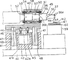
Figure 11 is the cutaway view of the 10th embodiment.
Figure 12 is the right view of the 10th embodiment.
Figure 13 is that side view is removed in the part of the 11st embodiment.
Figure 14 is the figure that sees from the arrow A direction of Figure 13.
Below in conjunction with the description of drawings embodiments of the invention.
Fig. 1 is the ideograph of oscillator, resonator and the ultrasonic vibration three position relation of expression the 1st embodiment.Among Fig. 1, oscillator 1 is by the electric power of supplying with from supersonic generator not shown in the figures the ultrasonic vibration of longitudinal wave of assigned frequency and electric acoustic converter or the electric vibratory transducer of being exported, be made up of piezoelectric element that electric energy is converted to mechanical energy or magnetostriction element etc. to take place, and by headless screw not shown in the figures and screwed hole not shown in the figures resonator 2 is combined with the output of ticker 1 is coaxial.Resonator 2 has the length with 5/2 wavelength of resonant frequency assigned frequency and the ultrasonic vibration resonance that comes as the longitudinal wave transmission from oscillator 1, that 6 maximum vibration amplitude points f1, f3, f5, f7, f9, f11 and 5 minimum vibration amplitude points f2, f4, f6, f8, f10 are provided.
In the occasion of this embodiment, resonator 2 has the shaft-like ultrasonic horn (ホ-Application) 3 that constitutes with titanium class alloy, 2 shaft-like boosters (プ-ス -) 4,5 of using arbitrary materials such as titanium, aluminium or the iron through quenching to constitute.2 boosters 4,5 are by headless screw not shown in the figures and screwed hole not shown in the figures and combine with the both sides of ultrasonic horn 3 are coaxial.Ultrasonic horn 3 has the length of 3/2 wavelength from maximum vibration amplitude points f3 to maximum vibration amplitude points 9, has to overlook into criss-cross vibration converter section 3a with by headless screw not shown in the figures and screwed hole and coaxial 2 flare 3b, the 3c that combine in its both sides not shown in the figures.Vibration converter section 3a keeps the ultrasonic vibration of transmitting from oscillator 1 original straightline propagation direction and is converted to vertical direction, is criss-cross lower face at it and protrudes that to be provided with minimum vibration amplitude points f6 be the ring-type conjugation 3d of portion at center.The 3d of conjugation portion imposes on the ultrasonic vibration both sides' of the ultrasonic vibration of straightline propagation direction and vertical direction resultant vibration energy and is engaged part Wa (see figure 3).
Ultrasonic horn 3 is provided with heater 6,7 in the part except that the 3d of conjugation portion.Heater the 6, the 7th can convert electrical energy into the electric heater of heat energy, for example, in metal enclosure interior the member that electric energy is converted to heat energy is installed in the electric insulation mode, and be provided with from the outwardly directed electric wire 6a of housing, 7a, the housing insertion is installed in the last heater that parallel direction forms below it at minimum vibration amplitude points f4, f8 place of flare 3b, 3c with in hole 3e, the 3f, therefrom heater is installed on the resonator 2.
When resonator 2 being installed on ultrasonic vibration joint device shown in Figure 3 described later, heater is leaving mouth with hole 3e, 3f at the back side that is positioned at ultrasonic vibration joint device one side of ultrasonic horn 3, if the housing of heater 6,7 is inserted heater hole 3e, 3f from this opening, electric wire 6a, 7a just can not hinder the joint operation.In this occasion, no matter heater with front one side of hole 3e, 3f be connect or all can of sealing, if but positive the sealing, then heater 6,7 heats that produced just reduce from the chance that the opening of a positive side distributes to ultrasonic horn 3 outsides, make from heater 6,7 goodly, can suitably heat the 3d of conjugation portion with the small amount of thermal energy of heater 6,7 to the heat transfer efficiency of ultrasonic horn 3.
Again, because vibration converter section 3a has minimum vibration amplitude points f6, if so heater 6,7 is not set at flare 3b, 3c, but shown in dotted line among the c figure of Fig. 1, at vibration converter section 3a a heater 8 the same with heater 6,7 is set, heat is stably worked at the 3d of conjugation portion.
In above-mentioned two boosters 4,5, booster 4 has the length of 1/2 wavelength from maximum vibration amplitude points f1 to maximum vibration amplitude points f3, and booster 5 then has the length of 1/2 wavelength from maximum vibration amplitude points f9 to maximum vibration amplitude points 11.Faying face 9,10 between booster 4,5 and the ultrasonic horn 3 is positioned at maximum vibration amplitude points f3, f9 place.Booster 4,5 is provided with concentric circles support portion 4a, the 5a that radially protrudes laterally from its outer peripheral face.
Resonator 2 is represented with the waveform that solid line L1, L2 are described with the moment displacement from the ultrasonic vibration of the ultrasonic vibration resonance of oscillator 1.The waveform of solid line L1 is represented to transmit and with the ultrasonic vibration of vibration converter section 3a straightline propagation, the waveform of solid line L2 is represented with vibrating the ultrasonic vibration that converter section 3a is converted to vertical direction from oscillator 1.The stress displacements that take place in resonator 2 inside along with the displacement of this ultrasonic vibration, its maximum vibration amplitude points f1, f3, f5, f7, f9, f11 become the minimum stress point, minimum amplitude point f2, f4, f6, f8, f10 then become maximum stress point, about this point, the ultrasonic wave theory illustrates.
Fig. 2 is the ideograph of oscillator, resonator and the ultrasonic vibration three position relation of expression the 2nd embodiment.Among Fig. 2, being identical with the 1st embodiment 2 booster 4,5 usefulness headless screw not shown in the figures and screwed hole with the resonator 20 of oscillator 1 combination does coaxial the combination with the both sides with the shaft-like ultrasonic horn 21 of titanium class alloy formation, have and from the ultrasonic vibration of oscillator 1 as the longitudinal wave transmission with assigned frequency resonance, provide 5 maximum vibration amplitude points f21, f23, f25, f27, f29 and 4 minimum vibration amplitude points f22, f24, f26, f28, the length of 2 wavelength of resonant frequency.
Occasion at this embodiment, ultrasonic horn 21 has the length of 1 wavelength from maximum vibration amplitude points f23 to maximum vibration amplitude points f27, central portion at ultrasonic horn 21, the 21a of conjugation portion is positioned at maximum vibration amplitude points f25 place, and radially protrudes laterally from the outer peripheral face of ultrasonic horn 21.
Again, ultrasonic horn 21 is provided with the heater identical with the 1st embodiment 6,7 in the part except that the 21a of conjugation portion.Heater 6,7 is identical with the 1st embodiment, inserts the minimum vibration amplitude points f24, the f26 place that are installed at ultrasonic horn 21 heater that form, parallel below it with in hole 21b, the 21c.
The moment displacement of the ultrasonic vibration that this resonator 20 takes place is represented with the waveform that solid line L3 is described.
Fig. 3 is to use the stereogram of the 3rd embodiment of ultrasonic vibration joint device of the resonator 20 of the resonator 2 of the 1st example or the 2nd embodiment.In Fig. 3, the preceding side lower part of device body 23 has the working space 24 that opens wide about reaching forwardly, is provided with cylinder 25 in the upper interior portion of the device body 23 that is separated out working space 24 tops.Support 26 is equipped with in lower end at the piston rod 25a that stretches out downwards of cylinder 25.Support 26 is keeping the resonator 2 or the resonator 20 that combine with oscillator 1 with the horizontal state that supports at two places in the upper interior of working space 24.
The bottom that is separated out the device body 23 at working space 24 backs is arranged on the base plate 27, and this base plate 27 becomes such as ultrasonic vibration joint device is installed in pedestal required on the production line.Loading stage 28 is set on base plate 27, is used to load a plurality of overlapped joint Wa of member W1, W2 that are engaged.Loading stage 28 is arranged on the bottom of working space 24 inside, and is coaxial at above-below direction with piston rod 25a and the 3d of conjugation portion or 21a.Loading stage 28 top when piston rod 25a stops at the rising extreme position, following parallel at certain intervals relative with 3d of conjugation portion or 21a at above-below direction.
When adopting the structure of present embodiment, air feed path by pressure air supply circuit not shown in the figures switches, make the piston rod 25a of cylinder 25 do to shrink driving, 3d of conjugation portion or 21a with the vertical direction of direction from oscillator 1 to resonator 2 or 20 that transmit ultrasonic vibrations from, after upwards breaking away from the direction rising predetermined distance of loading stage 28, the contraction of piston rod 25a drives and stops, 3d of conjugation portion or 21a stop at the rising extreme position, thereby form below 3d of conjugation portion or 21a and between above the loading stage 28 for being engaged member W1, the regulation space that W2 comes in and goes out.Stop under the state of rising extreme position at this 3d of conjugation portion or 21a, be loaded into joint operating area above the loading stage 28 with overlapped state being engaged member W1, W2.
In addition, air feed path by the pressure air supply circuit switches, make piston 25a do to stop at the falling-threshold position after elongation drives, in this stopped process, the joint Wa that is engaged member W1, W2 remains between them with the state that is engaged service portion 3d or 21a and loading stage 28 pressurizations.
After this pressurization to joint Wa keeps finishing, or before pressurization keeps, provide electric energy to oscillator 1, make oscillator 1 that ultrasonic vibration take place,, make its heating simultaneously to heater 6,7 supply of electrical energy from ultrasonic oscillator.Resonator 2 or 20 and from the ultrasonic vibration generation resonance of oscillator 1,3d of conjugation portion or 21a vibrate with the maximum vibration amplitude in the direction vertical with the compression aspect of cylinder 25 is carried out side by heater 6,7 simultaneously and heats.Like this, between the faying surface of joint Wa, the heat summation of just having concentrated the heat that produced by ultrasonic vibration and having accepted from heater 6,7 forms engages energy, even do not improve the energy of ultrasonic vibration especially or strengthen plus-pressure, also can carry out good non-solder joints at short notice between this faying surface.
In the present embodiment, because of support portion 4a, 5a are located at minimum vibration amplitude points f2, the f8 of conjugation portion 3d both sides or f22, f28 place, so the part of the ultrasonic vibratory energy that transmits to the 21a of conjugation portion of the 3d of conjugation portion of resonator 2 or resonator 20 from oscillator 1 can be delivered to 3d of conjugation portion or 21a from oscillator 1 effectively, and can supported 4a, 5a not consume.Thereby the bond strength of 3d of conjugation portion or 21a is uniform and stable, engages bad incidence and significantly reduces.
Again, after the joint of aforementioned joint Wa finishes, the switching of the air supply system by the air supply circuit, making cylinder 25 do to shrink drives, 3d of conjugation portion or 21a rise and stop at the rising extreme position from the falling-threshold position, in this course, after the pressurization of the 3d of conjugation portion or 21a and 28 couples of joint Wa of loading stage keeps being disengaged, what the 3d of conjugation portion or 21a broke away from upside is engaged member W, the joint Wa that finishes by this joint is formed a plurality of member W1 that are engaged of one, W2 takes out from the regulation space that forms between loading stage 28 and 3d of conjugation portion or 21a, and a procedure of joint promptly comes to an end.
As the 3rd embodiment, making the occasion that two places support with 26 pairs of resonators 2 of support or 20, if the 4th embodiment of image pattern 4 is such, support arm 26b is separated with the body 26a of support 26, and this support arm 26b is installed on the body 26a through guide such as transverse-roller 26c, this support arm 26b can be slided along the direction of principal axis of resonator 2 or 20, the part of support 26 is moved freely, and absorb the flexible of resonator 2 that the heat transfer because of heater 6,7 causes or 20, then can reduce the energy loss of ultrasonic vibration.
Below in conjunction with the different shape of Fig. 5-8 explanation ultrasonic horn and and heater between combination.The ultrasonic horn the 30,32,34, the 36th of 4-7 embodiment shown in Fig. 5-8 forms shaft-likely with titanium class alloy, this titanium class alloy has 1/2 wavelength length by the ultrasonic frequency vibratory that carries out resonance shown in the dotted line among each figure.
The ultrasonic horn 30 of the 5th embodiment among Fig. 5 has the plat part 30b up and down that the binding instrument is used at the columnar portion 32a from maximum vibration amplitude points f30 to minimum vibration amplitude points f31, has the rake 30c that tilts gradually to the datum line (zero line) of vibration amplitude from plat part 30b in part from minimum vibration amplitude points f31 to maximum vibration amplitude points f32, part at maximum vibration amplitude points f32, the a plurality of rectangle conjugation 30d of portion that protrude up and down from rake 30c are separated and form a line, in the part of minimum vibration amplitude points f31, insert heater and be arranged in parallel with the heater 31 and the 30d of conjugation portion of electric heater of hole 30e and so on.Symbol 31a represents the electric wire of heater 31.
The ultrasonic horn 32 of the 6th embodiment among Fig. 6 has the plat part 32b up and down that the binding instrument is used at the columnar portion 32a from maximum vibration amplitude points f30 to minimum vibration amplitude points f31, has the rake 32c that tilts gradually to the datum line (zero line) of vibration amplitude from plat part 32b in part from minimum vibration amplitude points f31 to maximum vibration amplitude points f32, part at maximum amplitude points f32, has the rectangle conjugation 32d of portion that protrudes up and down from rake 32c, in the part of minimum vibration amplitude points f31, insert and to be installed in heater and to be arranged in parallel with the heater 33 and the 32d of conjugation portion of electric heater in the 32e of hole and so on.Symbol 33a represents the electric wire of heater 33.
Shown in above-mentioned the 4th, the 5th embodiment, at 30d of conjugation portion or 32d is the occasion of wide cut formula, if the direction of stretching out with 30d of conjugation portion or 32d in ultrasonic horn 30 or 32 is provided with heater 31 or 33 abreast, then can suppress the fluctuation of the vibration amplitude of ultrasonic horn 30 or 32, realize good joint.
The ultrasonic horn 34 of the 7th embodiment among Fig. 7 has the recess 34b that the binding instrument is used at the columnar portion 34a from maximum vibration amplitude points f30 to minimum vibration amplitude points f31, also have the prismatic 34c of portion and the slick and sly rake 34d that is connected of columnar portion 34a to maximum vibration amplitude points f32 with minimum vibration amplitude points f31, part at maximum vibration amplitude points f32, be provided with the rectangle conjugation 34e of portion that protrudes forwards, backwards from the prismatic 34c of portion, in the part of minimum vibration amplitude points f31, insert and to be installed in heater and to be arranged in parallel with the heater 35 and the 34d of conjugation portion of electric heater in the 34f of hole and so on.Symbol 35a represents the electric wire of heater 35.
The ultrasonic horn 36 of the 8th embodiment among Fig. 8 has the recess 36b that the binding instrument is used at the thick columnar portion 36a from maximum vibration amplitude points f30 to minimum vibration amplitude points f31, also have the thin columnar portion 36c and the slick and sly rake 36d that is connected of thick columnar portion 36a to maximum vibration amplitude points f32 with minimum vibration amplitude points f31, part at maximum vibration amplitude points f32, be spaced apart at circumferencial direction to a plurality of rectangle conjugation 36e of portion that radially protrude from columnar portion 36c, in the part of minimum vibration amplitude points f31, insert and to be installed in heater and to be arranged in parallel with the heater 37 and the 36e of conjugation portion of electric heater in the 36f of hole and so on.Symbol 37a represents the electric wire of heater 37.
When the 34e of conjugation portion or 36e shown in above-mentioned the 7th, the 8th embodiment, it is the occasion of narrow type, even in the ultrasonic horn that dotted line is shown in 34 or 36 by Fig. 7 heater 35 or 37 are set, and do not consider the protrusion direction of 34e of conjugation portion or 36e, also can not produce the fluctuation of the vibration amplitude of ultrasonic horn 34 or 36, can realize good joint.
The 9th embodiment of the ultrasonic vibration joint device of the resonator 30,32,34,36 of Fig. 9-10 expression use 5-8 embodiment.Among Fig. 9, on half part of device body 40, be provided with the base portion 41 of pressing mechanism.Be provided with cylinder 42 in the recess 41a that on base portion 41, forms as pressurized source.The piston rod 42a that stretches out to the top of cylinder 42 links to each other with support 43.In the occasion of present embodiment, the upper end of piston rod 42a is installed in the moveable block 44 that is arranged at below the support 43 with the state that can not extract downwards.Moveable block 44 is liftably chimeric to be installed on the guide rod 45 that is fixed in below the support 43, and is installed in from guide rod 45 bottoms and the reinforcing upward of the helical spring 46 between the moveable block 44 that moveable block 44 is stretched out.At the right and left of moveable block 46, downward direction is installed with the guiding rotating shaft 47 that splined shaft constitutes below support 43.Guiding rotating shaft 47 cooperates with pilot bushing 48 sliding-contact liftably on correspondingly being installed in base portion 41.The resonator 49 that connects oscillator 1 is housed on the top of support 43.Resonator 49 has such as resonator 36 and booster 50 in the resonator 30,32,34,36 shown in the 5-8 embodiment.Booster 50 is contained in the vibration blocking supporting member 51 of adjustable in length.The inside of the 1st cylindrical shell 54 of the 1st dividing plate (ダ イ ヤ Off ラ system) 52 being installed with screw 53 at vibration blocking supporting member 51 holds booster 50, the booster 50 that stretches out from the 1st cylindrical shell 54 enters the inside that the 2nd cylindrical shell 57 of the 2nd dividing plate 55 is installed with screw 56, simultaneously become coaxial shape the 2nd cylindrical shell 57 and the 1st cylindrical shell 54 screw threads are chimeric, when the front and back end of booster 50 contacts with the 2nd dividing plate 55 with the 1st dividing plate 52, rotate the nut of adorning on the 1st cylindrical shell 54 58 and make it and the 2nd cylindrical shell 57 joins, become the double nut form, regulating therefrom becomes the length consistent with booster 50.By headless screw not shown in the figures and screwed hole, oscillator 1 across the 1st dividing plate 52 and with coaxial shape be contained in the booster 50 of this vibration blocking supporting member 51 inside the rear end do coaxial the combination, and by headless screw and screwed hole not shown in the figures, ultrasonic horn 36 is done coaxial the combination across the 2nd dividing plate 55 with the front end of booster 50, then, the top that supporting member 51 is installed in support 43 is interdicted in vibration, so that oscillator 1 resonator 49 is arranged on the support 43 as shown in Figure 9.In the place ahead of aforementioned base portion 41, on device body 40, be provided with loading stage 59 again.The inside that is engaged the topmost of member W1, W2 at the loading of loading stage 59 is provided with the heater 60 that is made of electric heater.
When adopting the structure of present embodiment, because the elongation of cylinder 42 action, the 36e of conjugation portion with the vertical direction of direction of transfer from oscillator to resonator 49 that transmit ultrasonic vibrations from, after upwards breaking away from the direction rising predetermined distance of loading stage 59, the elongation action of aforementioned cylinder 42 stops, and forms below the 36e of conjugation portion and between above the loading stage 59 for being engaged the regulation space that member W1, W2 come in and go out.Under this state, be loaded in joint operating area above the loading stage 59 with overlapped state with being engaged member W1, W2.Then, cylinder 42 is made contractive action, and stop at the falling-threshold position, in this course, when the 36e of conjugation portion when being engaged member 36e and contacting, as shown in figure 10, because of moveable block 44 compresses elastomeric 46 descend, so elastomer 46 absorbs the impact energy of the conjugation 36e of portion for engagement member W1, W2.Then, with being engaged service portion 36e and loading stage 59 Wa pressurization in joint is remained between them.
After the pressurization of this joint Wa keeps finishing, or before pressurization keeps, to oscillator 1 supply of electrical energy and make oscillator 1 that ultrasonic vibration take place, make its heating to heater 37,60 supply of electrical energy simultaneously from ultrasonic oscillator not shown in the figures.About providing the electric energy that makes its vibration to this oscillator 1, sensor not shown in the figures can be set on support 43, on moveable block 44, block is set, when elastomer 46 has been compressed ormal weight as shown in Figure 10, sensor promptly detects block, according to this detection signal, begin from ultrasonic oscillator to oscillator 1 supply of electrical energy, and make oscillator 1 vibration.In addition, about providing electric energy, if the fever time of heater 37,60 is too short to aforementioned heater 37,60, then unstable, so if can engage rising movingly of operation and continuous supply of electrical energy with continuous, the heating that then can stablize heater 37,60 makes it be fit to engage operation.And, resonator 49 and ultrasonic vibration generation resonance from oscillator 1, the 36e of conjugation portion vibrates with the maximum vibration amplitude in the direction shown in vertical with the compression aspect of cylinder 49, the arrow X, is done other heating by heater 37,60 simultaneously.Like this, between the faying surface of joint Wa, promptly concentrated the energy that engages that the heat that produced by ultrasonic vibration and heat summation from heater 37,69 acceptance form, even do not improve the energy of ultrasonic vibration or strengthen plus-pressure, can realize good non-solder joints at short notice between this faying surface yet.
Figure 11-12 represents the 10th embodiment, is the heater 62 that is provided with around ultrasonic horn 61 with the hot blast heating.As ultrasonic horn 61, be from ultrasonic horn shown in Figure 8 36, to remove heater 37 and heater hole 36f, and be provided with the 61a of conjugation portion that is equivalent to the 36e of conjugation portion, reinstall in the support 43 of ultrasonic vibration joint device shown in Figure 9.Heater 62 is at the inner annular channels 62a that forms of the closed looped pipeline that surrounds ultrasonic horn 61 non-contiguously, is formed on the continuous blow-off outlet 62b of full Zhou Fangxiang on the pipeline internal perisporium relative with ultrasonic horn 61.Heater 62 usefulness screws 65 are installed in the front end of support plate 64, and 64 of this support plates are installed on the support 43 with screw 63.When heater 62 is installed, make 61 one-tenth concentric circles of heater 62 and ultrasonic horn on support plate 64, make the gap 66 of formation predetermined distance between itself and the ultrasonic horn 61 therefrom.Certain part at heater 62 outer peripheral faces is connecting flexible pipe 67, this flexible pipe 67 is connected with the blow-off outlet that the source takes place the hot blasts such as air blast that are provided with electric heater not shown in the figures, hot blast 68 is with after entering annular channels 62a to the rotating state of circumferencial direction from this flexible pipe 67, blow out equably to the outer peripheral face of ultrasonic horn 61 through blow-off outlet 62b from annular channels 62a, can carry out the side heating to ultrasonic wave 61 with this hot blast that blows out 68.
Figure 13-14 expression with ultrasonic vibration the 11st embodiment that is engaged the device that member engages with macromolecular compounds such as thermoplastic synthetic resin formation, Figure 13 represents to remove the installment state of resonator 74 of the part of support 71, and the states of Figure 13 are seen in resonator 74 backs that Figure 14 represents to remove this embodiment from the arrow A direction.In these figure, in device body 70, do lifting in arrow Y1 direction and drive with being installed in 72 pairs of supports 71 of cylinder on the device body 70, make simultaneously its along be located at and device body 70 between guides such as transverse-roller 73 and do the lifting guiding.Support 71 has the cradle portion 71a of guide one side and the cradle portion 71c of switching body one side that can be mounted thereon by hinge 71b with opening and closing, cradle portion 71a and the facial semicircular recess 71d of formation of docking of the cradle portion 71c that opens and closes body one side in guide one side, 71e, 71f, 71g, recess 71d at the cradle portion 71a of guide one side that resonator 74 is packed into, behind the 71e, the cradle portion 71c that opens and closes body one side is closed, screw 73 is screwed in from the screwed hole 71i in the facial formation of the free-ended butt joint of switching body one 71c of side stand portion, and be connected at the facial screwed hole 71h that forms of the free-ended butt joint of guide one 71a of side stand portion, therefrom resonator 74 support 71 inside of packing into.Resonator 74 is installed on the support 71 in such a way, promptly, by headless screw not shown in the figures and screwed hole booster 75 and oscillator 1 coaxial the combination, by headless screw not shown in the figures and screwed hole ultrasonic horn 76 and booster 75 coaxial combinations, clip the pars intermedia of oscillator 1 with recess 71d, the 71f of support 71, clip from booster 75 with recess 71e, the 71g of support 71 and to be the support portion 75a that concentric shape protrudes laterally, when engaging operation, block the support portion 75a of booster 75 from the recess 71e of support 71, end difference 71j that 71g protrudes to the inside.The thin footpath 76b of conjugation portion that ultrasonic horn 76 has the particle size foundation 76a of portion that is positioned at booster one side and extends to the tip from the 76a of foundation portion also has intersection at 76a of foundation portion and the 76b of conjugation portion, is the electric heater formula heater 77 that the heater that partly forms of minimum vibration amplitude points inserts in hole 76c.
When adopting the structure of present embodiment, by from ultrasonic oscillator not shown in the figures to oscillator 1 supply of electrical energy and make oscillator 1 that ultrasonic vibration take place, make resonator 74 that resonance take place, ultrasonic horn 76 vibrates in direction shown in the arrow Y2, simultaneously by making its heating to heater 77 supply of electrical energy, and ultrasonic horn 76 is carried out the side heating, can at short notice macromolecular compound be engaged well.
In addition, in each embodiment, as ultrasonic horn, for physical propertys such as the area of the material that conjugation portion met be engaged member or joint and thickness, have the various forms that a plurality of conjugation portion etc. is set in the top and bottom of prismatic state for example, can therefrom select to be suitable for most to be engaged the ultrasonic horn of physical propertys such as the shape of member or material.
Again, what illustrate in each embodiment is the example that resonator and oscillator output are directly combined, booster in the middle of can certainly using between resonator and oscillator and the vibration amplitude of conjugation portion is changed.The large-diameter portion of the rhabodoids that for example materials such as titanium, aluminium or quenching iron that this centre booster basis has the integral multiple length of 1/2 wavelength constitute makes the input and output of vibration amplitude change than (multiplying power) with the volume ratio of minor diameter.
Again, the L4 among Fig. 5-8 is the waveform of the moment displacement (vibration amplitude) of the ultrasonic vibration that caused by resonance of expression.
In each embodiment, resonant frequency is changed because of resonator is heated the back prolongation.So contraction in length of the resonator that can will make at normal temperatures for the temperature dependent rule of grasping from practice according to resonant frequency.The resonator of this shortening can prolong when being heated to set point of temperature by heater.By being used for making from the ultrasonic vibration of oscillator the resonator generation resonance of this prolongation, promptly with assigned frequency generation resonance, there is no question about for this for this resonator.For example if will when the set point of temperature that is heated to 250 ℃, make it that resonance take place with 40Khz, then to make resonator according to the length that with 41-42KHz resonance takes place when 25 ℃ of the normal temperature, certainly, also to depend on the material of resonator.
Claims (4)
1. ultrasonic vibration joint device, one side or both sides are moved in approaching direction mutually, be engaged the overlapped part pressurization that is engaged of member and remain between them a plurality of with the topmost of conjugation portion that is located at resonator and loading stage, and from the conjugation portion transmission ultrasonic vibration of oscillator to resonator, to be engaged thus between the faying surface partly and be engaged, it is characterized in that, as to establish the wavelength that is delivered to the resonant frequency of resonator from oscillator be λ, then resonator has the length of the integral multiple of 1/2 λ, have simultaneously the maximum vibration amplitude points at two ends, and resonator on the minimum vibration amplitude points between the maximum vibration amplitude points of two ends or a side of loading stage topmost or both sides be provided with the electric heater formula heater of contact with it.
2. ultrasonic vibration joint device according to claim 1, it is characterized in that, when being located at heater on the resonator, on the minimum vibration amplitude points of resonator, form heater and use the hole, and heater with the hole in insertion electric heater formula heater contact with it.
3. ultrasonic vibration joint device according to claim 1 is characterized in that, when heater is located at the topmost of loading stage, electric heater formula heater is located at the inside of the topmost of loading stage.
4. ultrasonic vibration joint device, one side or both sides are moved in approaching direction mutually, be engaged the overlapped part pressurization that is engaged of member and remain between them a plurality of with the topmost of conjugation portion that is located at resonator and loading stage, and from the conjugation portion transmission ultrasonic vibration of oscillator to resonator, to be engaged thus between the faying surface partly and be engaged, it is characterized in that, resonator and loading stage one side or both sides heater is set, simultaneously will for make loading stage or resonator one side or twocouese mutually approaching direction move and for one in the left and right sides support arm of the support of to being engaged part and doing that pressurization keeps resonator being done the support of two places with the conjugation portion of the topmost resonator of loading stage is mounted to rack body relatively along the axially movable state of resonator.
Applications Claiming Priority (6)
| Application Number | Priority Date | Filing Date | Title |
|---|---|---|---|
| JP213471/95 | 1995-08-22 | ||
| JP21347195 | 1995-08-22 | ||
| JP213471/1995 | 1995-08-22 | ||
| JP176726/1996 | 1996-07-05 | ||
| JP08176726A JP3078231B2 (en) | 1995-08-22 | 1996-07-05 | Ultrasonic vibration bonding equipment |
| JP176726/96 | 1996-07-05 |
Publications (2)
| Publication Number | Publication Date |
|---|---|
| CN1150924A CN1150924A (en) | 1997-06-04 |
| CN1074966C true CN1074966C (en) | 2001-11-21 |
Family
ID=26497524
Family Applications (1)
| Application Number | Title | Priority Date | Filing Date |
|---|---|---|---|
| CN96119926A Expired - Fee Related CN1074966C (en) | 1995-08-22 | 1996-08-22 | Ultrasonic vibration joint device |
Country Status (8)
| Country | Link |
|---|---|
| US (1) | US5730832A (en) |
| EP (1) | EP0761371B1 (en) |
| JP (1) | JP3078231B2 (en) |
| KR (1) | KR100342663B1 (en) |
| CN (1) | CN1074966C (en) |
| CA (1) | CA2183476C (en) |
| DE (1) | DE69607798T2 (en) |
| TW (1) | TW316245B (en) |
Families Citing this family (51)
| Publication number | Priority date | Publication date | Assignee | Title |
|---|---|---|---|---|
| JP3099942B2 (en) * | 1996-08-08 | 2000-10-16 | 株式会社アルテクス | Ultrasonic vibration bonding resonator |
| JP3409683B2 (en) * | 1998-03-17 | 2003-05-26 | 松下電器産業株式会社 | Bonding tool and bonding device for bumped electronic components |
| US5906694A (en) * | 1998-03-31 | 1999-05-25 | American Technology, Inc. | Ultrasonic tube welding and cutting apparatus and method |
| JP3487166B2 (en) * | 1998-04-21 | 2004-01-13 | 松下電器産業株式会社 | Bonding tool and bonding device for electronic components |
| JP3762111B2 (en) * | 1998-08-31 | 2006-04-05 | 京セラ株式会社 | Ultrasonic transducer |
| EP1010492B1 (en) * | 1998-12-10 | 2004-09-01 | Ultex Corporation | Ultrasonic vibration bonding method |
| JP3290632B2 (en) * | 1999-01-06 | 2002-06-10 | 株式会社アルテクス | Ultrasonic vibration bonding equipment |
| TW460345B (en) * | 1999-08-02 | 2001-10-21 | Arutekusu Kk | Joining device by ultrasonic vibration |
| JP3788351B2 (en) * | 2002-01-21 | 2006-06-21 | 松下電器産業株式会社 | Electronic component bonding apparatus and electronic component bonding tool |
| US7243894B2 (en) * | 2002-02-15 | 2007-07-17 | 3M Innovative Properties Company | Mount for vibratory elements |
| US20040060639A1 (en) * | 2002-08-13 | 2004-04-01 | Dawn White | Method of apparatus for ensuring uniform build quality during object consolidation |
| DE10249569B4 (en) * | 2002-10-24 | 2005-03-17 | Robert Bosch Gmbh | Tool head for mounting an electrical conductor on the contact surface of a substrate and method for performing the attachment |
| JP3966217B2 (en) | 2003-04-23 | 2007-08-29 | 松下電器産業株式会社 | Bonding apparatus and bonding tool |
| US7002283B2 (en) * | 2003-06-03 | 2006-02-21 | Asm Assembly Automation Ltd. | Ultrasonic transducer assembly |
| US6786384B1 (en) | 2003-06-13 | 2004-09-07 | 3M Innovative Properties Company | Ultrasonic horn mount |
| JP4278095B2 (en) * | 2003-12-26 | 2009-06-10 | 本多電子株式会社 | Ultrasonic radiator, ultrasonic radiation unit, ultrasonic radiation device, and ultrasonic treatment device using the same |
| US7110625B2 (en) | 2004-09-16 | 2006-09-19 | Formguard Inc. | Apparatus to induce stress into a fiber optic cable to detect security fence climbing |
| DE102004045575A1 (en) | 2004-09-17 | 2006-04-06 | Hesse & Knipps Gmbh | Ultrasonic transducer with a sensor arranged in the bearing |
| KR100578139B1 (en) * | 2004-10-05 | 2006-05-10 | 삼성전자주식회사 | Cleaning probe and Megasonic cleaning apparatus having the same |
| JP2006135249A (en) * | 2004-11-09 | 2006-05-25 | Fujitsu Ltd | Ultrasonic packaging method and ultrasonic packaging apparatus used for the same |
| US20060144906A1 (en) * | 2005-01-05 | 2006-07-06 | Sheehan James F | Ultrasonic welder with high-Q tool |
| JP2008078272A (en) * | 2006-09-20 | 2008-04-03 | Athlete Fa Kk | Ultrasonic vibration welding apparatus |
| JP2008218528A (en) * | 2007-02-28 | 2008-09-18 | Fujitsu Ltd | Method for mounting electronic part and production device |
| JP4941268B2 (en) * | 2007-12-17 | 2012-05-30 | 富士通株式会社 | Wire bonding method and wire bonding apparatus |
| JP5313751B2 (en) * | 2008-05-07 | 2013-10-09 | パナソニック株式会社 | Electronic component mounting device |
| JP4683100B2 (en) * | 2008-09-17 | 2011-05-11 | パナソニック株式会社 | Bonding apparatus and bonding tool |
| JP5281550B2 (en) * | 2008-12-08 | 2013-09-04 | パナソニック株式会社 | Bonding tool, electronic component mounting apparatus, and electronic component mounting method |
| JP5491081B2 (en) * | 2009-06-22 | 2014-05-14 | 株式会社アルテクス | Resonator for ultrasonic vibration metal bonding |
| US7971769B2 (en) * | 2009-11-02 | 2011-07-05 | GM Global Technology Operations LLC | Quick change over tooling for a welder |
| EP2327534A1 (en) * | 2009-11-25 | 2011-06-01 | Telsonic Holding AG | Method and device for welding workpieces |
| US8082966B2 (en) | 2010-03-12 | 2011-12-27 | Edison Welding Institute, Inc. | System for enhancing sonotrode performance in ultrasonic additive manufacturing applications |
| JP5082081B2 (en) * | 2010-07-20 | 2012-11-28 | 株式会社アドウェルズ | Ultrasonic vibration bonding equipment |
| EP2457683A1 (en) * | 2010-11-25 | 2012-05-30 | Telsonic Holding AG | Torsional welding |
| US8408445B1 (en) * | 2011-09-30 | 2013-04-02 | GM Global Technology Operations LLC | Actively controlled vibration welding system and method |
| WO2014042005A1 (en) * | 2012-09-12 | 2014-03-20 | 株式会社Gsユアサ | Electricity storage device and processs for producing electricity storage device |
| DE102013103887A1 (en) * | 2013-04-17 | 2014-10-23 | Schunk Sonosystems Gmbh | Ultrasonic welding device |
| WO2015073126A1 (en) * | 2013-11-12 | 2015-05-21 | Dukane Corporation | Energy director joint design for ultrasonic welding of thermoplastics |
| CN107922071B (en) * | 2015-08-31 | 2020-10-09 | 凸版印刷株式会社 | Ultrasonic sealing device |
| KR101698837B1 (en) | 2016-09-05 | 2017-01-23 | 화이버트론 주식회사 | Intrusion sensing fence system |
| US10052714B2 (en) * | 2016-10-14 | 2018-08-21 | Sonics & Materials, Inc. | Ultrasonic welding device with dual converters |
| US10381321B2 (en) * | 2017-02-18 | 2019-08-13 | Kulicke And Soffa Industries, Inc | Ultrasonic transducer systems including tuned resonators, equipment including such systems, and methods of providing the same |
| EP3600700A1 (en) * | 2017-03-21 | 2020-02-05 | Telsonic Holding AG | Torsional ultrasonic processing systems |
| KR101922184B1 (en) * | 2017-07-25 | 2018-11-26 | 세메스 주식회사 | Apparatus for processing a substrate |
| EP3807080A1 (en) | 2018-06-13 | 2021-04-21 | Dukane IAS, LLC | Methods for determining a melt layer thickness associated with a predetermined weld strength based on a correlation therebetween |
| DE102018132838A1 (en) * | 2018-12-19 | 2020-06-25 | Herrmann Ultraschalltechnik Gmbh & Co. Kg | Ultrasonic welding system with bracket |
| JP6757837B1 (en) * | 2019-08-30 | 2020-09-23 | 株式会社高田工業所 | Support structure of ultrasonic resonator and ultrasonic vibration processing equipment |
| US11697172B2 (en) * | 2019-09-05 | 2023-07-11 | Ohio State Innovation Foundation | Systems and methods for joining and repair using ultrasonic additive manufacturing with a contoured sonotrode |
| CN112438249B (en) * | 2020-11-26 | 2022-07-08 | 贵州电网有限责任公司 | Underground optical cable and cable-based pipeline rat repelling system and method |
| US11434189B1 (en) | 2021-10-20 | 2022-09-06 | I-Mei Foods Co., Ltd. | Method for isolating curcuminoids from turmeric rhizome |
| EP4169523A1 (en) | 2021-10-20 | 2023-04-26 | I-Mei Foods Co., Ltd. | Method for isolating curcuminoids from turmeric rhizome |
| US20240116126A1 (en) * | 2022-10-11 | 2024-04-11 | Asmpt Singapore Pte. Ltd. | Ultrasonic transducer operable at multiple resonant frequencies |
Citations (3)
| Publication number | Priority date | Publication date | Assignee | Title |
|---|---|---|---|---|
| US4529115A (en) * | 1983-04-12 | 1985-07-16 | Fairchild Industries, Inc. | Thermally assisted ultrasonic welding apparatus and process |
| EP0541116A2 (en) * | 1991-11-08 | 1993-05-12 | Matsushita Electric Industrial Co., Ltd. | Method for bonding lead with electrode of electronic device |
| US5240166A (en) * | 1992-05-15 | 1993-08-31 | International Business Machines Corporation | Device for thermally enhanced ultrasonic bonding with localized heat pulses |
Family Cites Families (8)
| Publication number | Priority date | Publication date | Assignee | Title |
|---|---|---|---|---|
| DE541116C (en) * | 1932-01-08 | Ernst Curt Loesche | Device for separating dust | |
| US3752380A (en) * | 1972-03-13 | 1973-08-14 | Branson Instr | Vibratory welding apparatus |
| US4462849A (en) * | 1982-04-23 | 1984-07-31 | Cosden Technology, Inc. | Method of oscillatory bonding |
| US4514242A (en) * | 1982-04-23 | 1985-04-30 | Vercon Inc. | Methods for oscillatory bonding of dissimilar thermoplastic materials |
| EP0367705A3 (en) * | 1988-10-31 | 1990-09-26 | International Business Machines Corporation | Laser assisted ultrasonic bonding |
| DE4032192C2 (en) * | 1990-10-08 | 1994-05-26 | Michael Kising | Device for heating an ultrasonic soldering or welding head |
| GB2271306B (en) * | 1992-10-06 | 1995-06-07 | Emhart Inc | Tab process control system |
| JPH06342830A (en) * | 1993-06-02 | 1994-12-13 | Matsushita Electric Ind Co Ltd | Wire bonding method and its device |
-
1996
- 1996-07-05 JP JP08176726A patent/JP3078231B2/en not_active Expired - Fee Related
- 1996-08-16 CA CA002183476A patent/CA2183476C/en not_active Expired - Fee Related
- 1996-08-20 TW TW085110141A patent/TW316245B/zh not_active IP Right Cessation
- 1996-08-20 US US08/699,863 patent/US5730832A/en not_active Expired - Lifetime
- 1996-08-22 KR KR1019960034839A patent/KR100342663B1/en not_active IP Right Cessation
- 1996-08-22 CN CN96119926A patent/CN1074966C/en not_active Expired - Fee Related
- 1996-08-22 EP EP96113503A patent/EP0761371B1/en not_active Expired - Lifetime
- 1996-08-22 DE DE69607798T patent/DE69607798T2/en not_active Expired - Lifetime
Patent Citations (3)
| Publication number | Priority date | Publication date | Assignee | Title |
|---|---|---|---|---|
| US4529115A (en) * | 1983-04-12 | 1985-07-16 | Fairchild Industries, Inc. | Thermally assisted ultrasonic welding apparatus and process |
| EP0541116A2 (en) * | 1991-11-08 | 1993-05-12 | Matsushita Electric Industrial Co., Ltd. | Method for bonding lead with electrode of electronic device |
| US5240166A (en) * | 1992-05-15 | 1993-08-31 | International Business Machines Corporation | Device for thermally enhanced ultrasonic bonding with localized heat pulses |
Also Published As
| Publication number | Publication date |
|---|---|
| EP0761371A1 (en) | 1997-03-12 |
| CA2183476C (en) | 1999-03-23 |
| TW316245B (en) | 1997-09-21 |
| CA2183476A1 (en) | 1997-02-23 |
| KR100342663B1 (en) | 2002-11-23 |
| JP3078231B2 (en) | 2000-08-21 |
| JPH09122934A (en) | 1997-05-13 |
| US5730832A (en) | 1998-03-24 |
| DE69607798D1 (en) | 2000-05-25 |
| KR970009968A (en) | 1997-03-27 |
| CN1150924A (en) | 1997-06-04 |
| EP0761371B1 (en) | 2000-04-19 |
| DE69607798T2 (en) | 2000-08-10 |
Similar Documents
| Publication | Publication Date | Title |
|---|---|---|
| CN1074966C (en) | Ultrasonic vibration joint device | |
| AU774545B2 (en) | Ultrasonic transducer with improved compressive loading | |
| US10399274B2 (en) | Method for using transverse sonotrode in ultrasonic welding | |
| US10016836B2 (en) | Sonotrode and anvil energy director grids for narrow/complex ultrasonic welds of improved durability | |
| US8376016B2 (en) | Sonotrode and anvil energy director grids for narrow/complex ultrasonic welds of improved durability | |
| US20150290873A1 (en) | Sonotrode and Anvil Energy Director Grids for Narrow/Complex Ultrasonic Welds of Improved Durability | |
| US20070080609A1 (en) | Low loss ultrasound transducers | |
| EP2743059B1 (en) | Retrofit of a form-fill-seal machine heat station with an advanced ultrasonic welding kit | |
| US8408445B1 (en) | Actively controlled vibration welding system and method | |
| US9993970B2 (en) | Cross seam joining device for joining a sealing seam for a flexible packaging | |
| NZ510968A (en) | Ultrasonic welding apparatus with sonotrode and anvil forming converging gap between inlet and outlet | |
| JPH1190329A (en) | Ultrasonic device | |
| CN105163926A (en) | ultrasonic welding device | |
| US20040035912A1 (en) | Ultrasonic transducer | |
| JPH09103740A (en) | Structure of driving apparatus for ultrasonic sealing device | |
| CN112827786A (en) | Ultrasonic treatment device | |
| CA2053135C (en) | Method and apparatus for joining thermoplastic workpieces by high frequency vibrations | |
| US6298012B1 (en) | Doubly resonant push-pull flextensional | |
| CA2831272A1 (en) | Retrofit of a form-fill-seal machine heat station with an advanced ultrasonic welding kit | |
| CN112756763A (en) | Transducer for generating torsional vibration and welding apparatus | |
| US3523845A (en) | Method and apparatus for joining a series of elements to a workpiece by ultrasonic energy | |
| KR20150097982A (en) | Ultrasonic welding and management system | |
| Bagyinszki et al. | ApplicAtion feAtures of ultrAsonic welding | |
| SU198796A1 (en) | ||
| CN115753564A (en) | Travelling wave sound field-based microsphere multi-mode control device and working method thereof |
Legal Events
| Date | Code | Title | Description |
|---|---|---|---|
| C06 | Publication | ||
| PB01 | Publication | ||
| C10 | Entry into substantive examination | ||
| SE01 | Entry into force of request for substantive examination | ||
| C14 | Grant of patent or utility model | ||
| GR01 | Patent grant | ||
| C17 | Cessation of patent right | ||
| CF01 | Termination of patent right due to non-payment of annual fee |
Granted publication date: 20011121 Termination date: 20120822 |