CN107363362B - Automatic bus bar welding machine - Google Patents
Automatic bus bar welding machine Download PDFInfo
- Publication number
- CN107363362B CN107363362B CN201710412516.0A CN201710412516A CN107363362B CN 107363362 B CN107363362 B CN 107363362B CN 201710412516 A CN201710412516 A CN 201710412516A CN 107363362 B CN107363362 B CN 107363362B
- Authority
- CN
- China
- Prior art keywords
- bus bar
- welding
- unit
- wheel
- straightening
- Prior art date
- Legal status (The legal status is an assumption and is not a legal conclusion. Google has not performed a legal analysis and makes no representation as to the accuracy of the status listed.)
- Active
Links
Images


Classifications
-
- B—PERFORMING OPERATIONS; TRANSPORTING
- B23—MACHINE TOOLS; METAL-WORKING NOT OTHERWISE PROVIDED FOR
- B23K—SOLDERING OR UNSOLDERING; WELDING; CLADDING OR PLATING BY SOLDERING OR WELDING; CUTTING BY APPLYING HEAT LOCALLY, e.g. FLAME CUTTING; WORKING BY LASER BEAM
- B23K3/00—Tools, devices, or special appurtenances for soldering, e.g. brazing, or unsoldering, not specially adapted for particular methods
- B23K3/08—Auxiliary devices therefor
- B23K3/087—Soldering or brazing jigs, fixtures or clamping means
-
- Y—GENERAL TAGGING OF NEW TECHNOLOGICAL DEVELOPMENTS; GENERAL TAGGING OF CROSS-SECTIONAL TECHNOLOGIES SPANNING OVER SEVERAL SECTIONS OF THE IPC; TECHNICAL SUBJECTS COVERED BY FORMER USPC CROSS-REFERENCE ART COLLECTIONS [XRACs] AND DIGESTS
- Y02—TECHNOLOGIES OR APPLICATIONS FOR MITIGATION OR ADAPTATION AGAINST CLIMATE CHANGE
- Y02P—CLIMATE CHANGE MITIGATION TECHNOLOGIES IN THE PRODUCTION OR PROCESSING OF GOODS
- Y02P70/00—Climate change mitigation technologies in the production process for final industrial or consumer products
- Y02P70/50—Manufacturing or production processes characterised by the final manufactured product
Abstract
The invention aims to provide an automatic bus bar welding machine aiming at the defects of low manual operation efficiency and complex introduced equipment structure when a bus bar is welded on a solar cell module in the prior art, which comprises a transmission unit, a simple side welding unit, a complex side welding unit, a positioning compensation unit, a sheet suction unit and a control unit.
Description
Technical Field
The invention relates to a solar cell string bus bar welding machine, in particular to an automatic solar cell string bus bar welding machine.
Background
The solar cell is an important component of a solar cell module and is formed by connecting a plurality of solar cells through solder strips, a plurality of solder strips are arranged on the surface of each solar cell in parallel, the end parts of the solder strips are arranged outside two sides of each solar cell, bus bars are arranged on the two side edges of each solar cell and are in welded connection with the solder strips, and current is collected through the solder strips. In the production of the prior art, most manufacturers need to rely on manpower to realize the welding of the welding strip and the bus bar of the battery piece in a manual interconnection mode, and a few manufacturers introduce bus bar automatic welding equipment from abroad, but the structure is more complicated, the occupied area is large, and the equipment cost is high.
The series-welded battery strings need to be laid at specified positions according to the process requirements of inter-string interconnection by an automatic bus bar welding machine, and then the bus bars are laid on the battery strings according to the requirements. The existing equipment has complex structure, large occupied area and high equipment cost and needs to be improved.
Disclosure of Invention
The invention aims to provide an automatic bus bar welding machine aiming at the defects of low manual operation efficiency, high manufacturing cost of introduced equipment and complicated structure and large occupied area when the bus bar welding is carried out on a solar cell module in the prior art.
The purpose of the invention is realized by the following technical scheme:
an automatic bus bar welding machine comprises a transmission unit (600), a simple side welding unit (140), a complex side welding unit (130), a positioning compensation unit (400), a sheet suction unit and a control unit, and is characterized in that the transmission unit comprises a transmission device (610), a correcting device (632) and a positioning device (631), a battery sheet is transmitted into a rack by the transmission device, the front and rear positions of the battery sheet in the rack are limited by the positioning device, and the left and right positions of the battery sheet are corrected by the correcting device;
the simple side welding unit (140) comprises a first bus bar providing device provided with a first tray, a first bus bar grabbing device (210) and a first welding device (110), wherein the first bus bar grabbing device (210) moves a bus bar (500) from the first tray to a welding position; the complex side welding unit (130) comprises a second bus bar providing device provided with a second bus bar tray (1452), a second bus bar grabbing device (220) and a second bus bar welding device (120), wherein the second bus bar grabbing device grabs bent bus bars from the second tray to a welding position;
the positioning compensation unit (400) comprises a visual positioning device (410) and a position compensation device, the visual positioning device (410) is used for acquiring the positions of the battery pieces, the position compensation device is used for adjusting the relative positions of the welding device I, the bus bar grabbing device I (210) and the battery pieces on the simple side and the relative positions of the welding device II and the bus bar grabbing device II and the battery pieces on the complex side according to the position information of the battery pieces, and the welding position and the bus bar laying position are adjusted;
the battery piece is lifted by the piece sucking unit, a laying position is reserved for the bus bar, and the battery piece is reset;
a first bus bar welding device of the simple side welding unit (140) is used for welding the linear bus bar with the welding strip on the simple side, a second bus bar welding device of the complex side welding unit (130) is used for welding the bent bus bar with the welding strip on the complex side, and then the transmission unit is used for transmitting the battery piece out of the rack;
the control unit controls the transmission unit, the simple side welding unit (140), the complex side welding unit (130), the positioning compensation unit and the sheet suction unit to perform coordinated actions;
further, the position compensation device comprises a simple side position compensation device and a complex side position compensation device, the simple side position compensation device comprises a first supporting platform, a first X-axis driving device and a first cross beam, the first X-axis driving device drives the first supporting platform to move in the X-axis direction, the first cross beam and the first bus bar providing device are arranged on the first supporting platform, the first welding device 110 and the first bus bar grabbing device 210) are arranged on the first cross beam through a Y-axis driving device, and the first Y-axis driving device drives the first bus bar grabbing device (210) and the first welding device (110) to move on the first cross beam; the complex side position compensation device comprises a second supporting platform, a second X-axis driving device and a second cross beam, wherein the second X-axis driving device drives the second supporting platform to move in the X-axis direction; (ii) a
Furthermore, the first bus bar welding device and the second bus bar welding device are both soldering iron welding devices consisting of soldering irons, soldering iron driving devices and base plates, the base plates are arranged on the inner side of the first supporting platform and the inner side of the second supporting platform, the base plates on the corresponding sides are respectively arranged along the first cross beam and the second cross beam and are positioned below the first cross beam and the second cross beam, the first Y-axis driving device and the second Y-axis driving device are respectively connected with the soldering iron driving devices on the corresponding sides, the soldering irons on the corresponding sides are driven by the soldering iron driving devices on the corresponding sides to be close to and far away from the base plates, and the bus bars are laid on the base plates on the corresponding sides through the sheet suction units;
furthermore, the first welding device and the second welding device both further comprise a cooling device consisting of a cooling block and a cooling block driving device, and the cooling block driving device drives the cooling block to be far away from and close to the base plate to rapidly cool the welded bus bar and the welded strip;
furthermore, the cooling iron driving device and the soldering iron driving device are both connected with the Y-axis driving device through the primary driving device, the cooling iron is arranged behind the soldering iron, and the cooling iron is driven by the cooling iron driving device to extend out and retract in an inclined manner;
furthermore, the first bus bar grabbing device is a sucker grabbing device, and a vacuum sucker component II, a material placing station of the first material disc, a welding station of a backing plate on the side corresponding to the first material disc, a soldering iron head of a soldering iron and the first bus bar grabbing device are positioned on the same straight line;
further, the bus bar providing device comprises a bus bar straightening device (1400) and a cutting device (1430), wherein the bus bar straightening device (1400) straightens the disc-shaped bus bar (500), the cutting device (1430) cuts the bus bar (500) into a specified length, and the bus bar enters the material receiving device (1450);
furthermore, the bus bar straightening device (1400) comprises a material roll, a guide wheel set (1410), a straightening wheel set (1420), a power roller set, a material receiving device and a cutting device (1430), wherein the guide wheel set comprises a guide wheel and a reverse wheel, the material receiving device is arranged outside one end of the backing plate on the corresponding side and positioned outside the material roll support, the straightening wheel set and the cutting device are positioned between the material roll support and the reverse wheel, the bus bar is introduced into the reverse wheel from the material roll through the guide wheel, enters the straightening wheel set after being turned by 180 degrees through the reverse wheel, then enters the power roller set, enters a cutting knife of the cutting device under the traction of the power roller set and is cut, a material groove is arranged on the material receiving device, and the length direction of the material groove is consistent with the length direction of the bus bar;
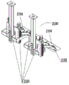
furthermore, the sheet suction unit comprises a simple side sheet suction unit and a complex side sheet suction unit, the simple side sheet suction unit and the complex side sheet suction unit both comprise a lifting device (2100) consisting of a lifting device and a vacuum chuck device, and the lifting device drives the vacuum chuck assembly to lift and lift or put down the battery sheet;
furthermore, the simple side suction piece unit comprises one lifting device, the complex side suction piece unit comprises at least two lifting devices, vacuum chuck assemblies of the lifting devices of the complex side suction piece unit are arranged in a row, and a lifting device of each lifting device is connected with the control unit.
By adopting the automatic bus bar welding machine with the structure, the alignment device and the positioning device of the transmission unit are combined with the position compensation device and the visual positioning device of the positioning compensation unit, so that the positions of the simple side welding device and the complex side welding device relative to the bus bar can be adjusted while the solar cell is positioned, the welding positioning is more accurate, the equipment structure is simple, the control is simple, the occupied area is small, the equipment cost is low, the welding positioning is accurate, and the welding quality is excellent.
Drawings
FIG. 1 is a schematic perspective view of an automatic bus bar welder according to an embodiment of the present invention;
FIG. 2 is a schematic top view of FIG. 1;
FIG. 3 is a schematic structural diagram of an embodiment of a simple side lifting device of an automatic bus bar welding machine according to the present invention.
FIG. 4 is a schematic view of a complex side lift apparatus of the automatic bus bar welder of the present invention;
FIG. 5 is a schematic structural diagram of an embodiment of a welding device of the automatic bus bar welding machine according to the present invention;
FIG. 6 is a schematic front view of FIG. 5;
FIG. 7 is a schematic structural diagram of an embodiment of a cutting device of the automatic bus bar welding machine according to the present invention;
FIG. 8 is a schematic structural diagram of an embodiment of a transmission unit of the automatic bus bar welder according to the present invention;
FIG. 9 is a schematic structural view of an embodiment of a single-side welding device of the automatic bus bar welding machine according to the present invention;
FIG. 10 is a schematic structural view of an embodiment of a complex side welding device of the automatic bus bar welder according to the present invention;
fig. 11 is a schematic view showing a connection structure and a positional relationship between a soldering iron and a cooling device of the automatic bus bar soldering machine according to the present invention.
Description of the reference numerals
400-positioning a compensation unit; 410-a visual positioning device; 403-a support platform; 404-platform driving means; 405-a beam; 406-Y axis drive; 410-positioning device 411-camera
500-a bus bar; 501-a primary driving device; 502-frame
600-a transmission unit 600; 610-a transmission device; 631-a positioning device; 632-a leveling device;
140-simple side welding unit
1400-bus bar straightening device; 1410-guide wheel set; 1411-roll holder; 1412-material roll; 1413-a fixed shaft; 1414-a guide wheel; 1415-a reversing wheel; 1416-limiting pin shaft; 1417 connecting the arms; 1418-a guide plate; 1419-guide holes;
1420-aligning the wheel set; 1421-upper straightening wheel; 1422 — axle one; 1423-axle two; 1424 — base; 1425-lower straightening wheels; 1426-mount;
1430-a cutting device; 1431 — a drive; 1432-cutter head; 1433-go scissors; 1434-handle of a knife; 1435-cutting knife; 1436-lower scissors; 1437-spindle; 1438-fixed plate; 1439-bottom plate; 1440-base.
1450-a material receiving device; 1451-Material disc 1
1460-power roller set; 1641-drive roll; 1462-driven roller; 1463-connecting seat; 1464-power plant; 1465-roller shaft; 1466-set bolts;
110-a first welding device; 102-a backing plate; 103-a cooling device; 104-a chilled iron drive; 105-cooling the iron; 106-soldering iron; 107-solder iron drive means; 201-vacuum chuck assembly two; 202-a second sucker driving device;
210-a first bus bar grabbing device;
130-complex side welding unit; 1452-material disc II; 220-bus bar grabbing device two; 120-welding device two;
2100-lift device 2101-lift device; 2102-suction cup; 2103-a mounting frame; 2104-a vacuum chuck assembly; 2201-cell slice group 2202-cell slice.
Detailed Description
The invention is further described below with reference to specific examples:
as shown in fig. 1 to 11, in the present invention, for convenience of description, one side of the cell plate to which the straight bus bar is welded is referred to as a simple side, and one side of the cell plate to which the bent bus bar is welded is referred to as a complex side. A cell sheet composed of a plurality of cell strings is referred to as a cell sheet group 2201, and a single cell sheet constituting the cell sheet group is referred to as a cell sheet 2202.
The automatic bus bar welding machine with the structure comprises a transmission unit 600, a simple side welding unit 140, a complex side welding unit 130, a positioning compensation unit, a suction piece unit, a control unit and a rack 502.
The transmission unit comprises a transmission device 610, a correcting device 632 and a positioning device 631, the correcting device is preferably arranged on a positioning stop block on the transmission device 610, the transmission device transmits the battery assembly to a welding station in the rack and is positioned back and forth by the positioning stop block, the correcting device 632 on two sides of the transmission device corrects the battery assembly, the battery sheet is accurately transmitted to a specified position under the combined action of the positioning device and the correcting device, and the welded battery sheet is conveyed out of the rack; the invention preferably adopts the following transmission unit for transmission: the transmission device is a synchronous belt transmission device, the correcting device adopts an air cylinder correcting device, the positioning stop block is arranged in front of the synchronous belt transmission device, and at least one pair of air cylinder correcting devices are respectively arranged on two sides of the synchronous belt transmission device.
The simple side welding unit 140 includes a bus bar straightening device 1400, a cutting device 1430, a bus bar grabbing device 210, and a welding device 110, wherein the bus bar straightening device 1400 straightens the disk-shaped bus bar 500, the cutting device 1430 cuts the bus bar 500 to a specified length, the disk-shaped bus bar is fed into the feeding disk 1451, the bus bar grabbing device 210 moves the bus bar to a specified position, and the bus bar welding device 110 welds the bus bar 500 to the welding strip on the simple side; the complex side welding unit 130 comprises a second bus bar tray 1452, a second bus bar grabbing device 220 and a second bus bar welding device 120, wherein the second bus bar grabbing device grabs bent bus bars from the second bus bar tray to a welding position, and the second bus bar welding device welds the bus bars and the welding strips on the complex side together;
the positioning compensation unit 400 comprises a visual positioning device 410 and a position compensation device, the visual positioning device 410 collects the positions of the battery pieces, the position compensation device respectively adjusts the relative positions of the first welding device, the first bus bar grabbing device 210 and the simple side battery piece and the relative positions of the second welding device, the second bus bar grabbing device and the complex side battery piece according to the position information of the battery pieces, and the welding position and the bus bar laying position are adjusted;
the battery piece is lifted by the piece sucking unit, a laying position is reserved for the bus bar, and the battery piece is reset;
the first bus bar welding device of the simple side welding unit 140 is used for welding the linear bus bar with the welding strip on the simple side, the second bus bar welding device of the complex side welding unit 130 is used for welding the bent bus bar with the welding strip on the complex side, and the transmission unit is used for transmitting the battery piece out of the rack;
the control unit controls the transmission unit, the simple side welding unit 140, the complex side welding unit 130, the positioning compensation unit and the suction piece unit to act in a coordinated way.
The positioning compensation unit preferably adopts the following structure: the visual positioning device 410 adopts a camera visual positioning system, cameras 411 are respectively arranged on the two sides of the battery piece on the rack, and the cameras acquire the position information of the battery piece and feed the position information back to the control unit; the position compensation device comprises a simple side position compensation device and a complex side position compensation device, the simple side position compensation device and the complex side position compensation device both comprise an X-axis displacement device and a Y-axis displacement device, and the X-axis displacement device comprises a supporting platform 403 and a driving support
A platform driving device 404 for supporting the platform to move in the X-axis direction, wherein the Y-axis shifting device comprises a beam 405 and a Y-axis driving device 406 arranged in the Y-axis direction, the bus bar straightening device 1400, a cutting device 1430, a first material tray 1451 and a first beam 1470 of the simple side welding unit 140 are all arranged on a first supporting platform (for convenience of description, names of devices of the simple side position compensation device and the complex side position compensation device are distinguished, a first suffix is added to a simple side, and a second suffix is added to a complex side), a first welding device and a first bus bar grabbing device are all arranged on a first beam, the first welding device and the first bus bar grabbing device are all connected with an output end of the first Y-axis driving device, the first supporting platform is driven by the first X-axis shifting device to move in the X-axis direction, so that the positions of the first welding device 1400, the first cutting device 1430, the first material tray 1451, the first beam 1470, the first bus bar grabbing device 210 in the X-axis direction are adjusted, and the positions of the first welding device, namely the first welding point and the first bus bar grabbing device are adjusted relative to the welding point; the second material tray and the second bus bar grabbing device of the complex side welding unit 130 are arranged on the second supporting platform, the second supporting platform is driven by the second X-axis shifting device to move in the X-axis direction, the second welding device is arranged on the second cross beam, and the second welding device is driven by the second Y-axis driving device to move on the second cross beam. The position compensation device with the structure divides the working area of the welding device into a simple side welding unit 140 and a complex side welding unit 130, the welding device of the simple side welding unit and the complex side welding unit, the bus bar grabbing device and the feeding device are all arranged on a supporting platform, the feeding device is respectively arranged on two supporting platforms, so that the positions of the devices of the simple side welding unit and the complex side welding unit are fixed and can move relatively, the positions of the devices of the complex side welding unit are fixed and can move relatively, the left side and the right side of the transmission unit are respectively provided with a correcting device for correcting the deflection of the battery piece and the front side and the back side of the battery piece are positioned by a positioning device, therefore, when the position precision between the welding device and the bus bar and between the bus bar and the battery piece needs to be adjusted, the position precision between the supporting platform I and the supporting platform II and the battery piece on the corresponding side can be adjusted by only adjusting the distances between the supporting platform I and the supporting platform II and the battery piece through an X-axis driving device, the position precision between the bus bar grabbing device and the battery piece can be adjusted conveniently and the position precision between the bus bar welding device and the battery piece is accurate, and the manipulator is preferred by the bus bar grabbing device. By adopting the position compensation device with the structure, all devices of the simple side welding unit 140 are arranged on the first supporting platform, so that synchronous X axial displacement of the first bus bar straightening device 1400, the cutting device, the first material disc, the first cross beam and the first bus bar grabbing device can be realized, and meanwhile, the welding device is arranged on the first cross beam and is moved in the Y-axis direction by the first Y-axis driving device, so that accurate positioning can be realized through simple position adjustment. In the same way, the complex side welding unit 130 can also realize accurate position compensation through simple position adjustment. In the simple side welding unit 140, it is preferable to arrange the first tray and the pad plate in a straight line, which makes the position adjustment easier and more reliable.
Preferably, the welding device I of the simple side welding unit and the welding device II of the complex side welding unit are of the same structure, and both adopt soldering iron welding devices consisting of soldering irons 106, backing plates 102 and soldering iron driving devices 107, in order to improve welding efficiency and welding quality, a cooling device 103 can be arranged on the welding unit, the cooling device consists of cooling irons 105 and cooling iron driving devices 104, the cooling iron driving devices are connected with output ends of the cooling iron driving devices, the cooling device is arranged on the cross beam through the cooling iron driving devices 104, and the cooling device can move on the cross beam under the driving of the Y-axis driving devices. In order to further improve the welding efficiency, the welding device and the cooling device are driven by the primary driving device 501 to reciprocate up and down at the same time and to be close to or far away from the bus bar welding point, the soldering iron driving device of the welding device and the cooling iron driving device of the cooling device are respectively connected with the primary driving device, the primary driving device is connected with the Y-axis driving device, and the Y-axis driving device drives the primary driving device to move on the beam. When the welding machine works, the Y-axis driving device drives the welding device and the cooling device to the positions of the corresponding base plates at the same time, the first-stage driving device drives the welding device and the cooling device to drop to a certain height at the same time and then stops driving, the soldering iron driving device drives the soldering iron to drop, after welding, the soldering iron driving device drives the soldering iron to rise, the cooling iron driving device drives the cooling iron to stretch out, and the cooling iron falls on a welding point to cool the welding point.
Straightening device and cutting device preferably adopt the alignment to cut the all-in-one: the bus bar straightening device 1400 comprises a bus bar straightening device 1400, a bus bar cutting device 1430 and a material receiving device 1450, wherein the bus bar straightening device 1400 comprises a material roll support 1411, a guide wheel set 1410, a straightening wheel set 1420 and a power roller set 1460. The material roll 1412 wound with the bus bar is rotatably arranged above the material roll support 1411 through a fixed shaft 1413, the bus bar 500 is led out downwards from the material roll 1412 and enters the straightening wheel set 1420 under the guidance of the guide wheel set 1410, the straightening wheel set 1420 comprises an upper straightening wheel 1421 and a lower straightening wheel 1425, the upper straightening wheel is rotatably arranged on a mounting seat 1426 through a first wheel axle 1422, the lower straightening wheel is rotatably arranged on a base 1424 through a second wheel axle 1423, and the mounting seat 1426 can be connected above the base 1424 through bolts. The bus bar passes through between the upper straightening wheel and the lower straightening wheel and is pressed by the upper straightening wheel and the lower straightening wheel, and then enters the power roller set 1460, the power roller set 1460 comprises a driving roller 1461 and a driven roller 1462, the driven roller is correspondingly arranged above the driving roller, the driven roller and the driving roller are rotatably arranged on a connecting seat 1463, one end of the driving roller is connected with a power device 1464, and the bus bar passes through between the driving roller and the driven roller and is pressed by the driving roller and the driven roller. Under the drive of the power device, the driving roller 1461 rotates and drives the driven roller 1462 to rotate, and due to the action of friction force, the bus bars are driven by the driving roller group to move forwards, and meanwhile, the bus bar movable material roll 1412 rotates to continuously provide materials. The bus bar also drives the upper and lower straightening wheels of the straightening wheel set 1420 to rotate, and the straightening effect is achieved by rolling the upper and lower straightening wheels. The straightened bus bars are ejected by the power roller sets and enter a bus bar cutting device 1430, the bus bar cutting device 1430 comprises a cutting knife 1435, the cutting knife 1435 comprises an upper shear 1433 and a lower shear 1436, the upper shear is rotatably connected with the lower shear through a connecting shaft 1437, the lower shear is fixed on a base 1440, and the upper shear is rotatably connected with the output end of the driving device 1431. The bus bar 500 passes between the upper and lower scissors, and the upper surface of the lower scissors is preferably slightly higher than or flush with the top cut surface of the drive roll 1461, so that the bus bar can be closely attached to the top of the lower scissors, which is advantageous for cutting. When cutting, the output end of the driving device 1431 extends outwards, the upper scissors are pushed to rotate around the connecting shaft 1437 towards the bus bar, and when the upper scissors and the lower scissors are closed, the bus bar is cut by the cutting knife 1435. The bus bar that is cut enters into receiving device 1450 on, receiving device can be charging tray one, sets up receiving groove 1451 on the charging tray one, and the length direction of receiving groove corresponds with the traffic direction of bus bar, for the entering charging tray that makes the bus bar can be stable, the width of charging tray one can be slightly wider than the width of bus bar 500, and the degree of depth of charging tray one can be slightly darker than the thickness of bus bar.
Preferably, the guide wheel group 1410 includes at least one guide wheel 1414 and a reverse wheel 1415, the reverse wheel can be disposed at the output end of the guide wheel group, the bus bar runs along the surface of the guide wheel 1414 to 180 ° behind the reverse wheel, wraps around the reverse wheel 1415, and then runs in the reverse direction towards the coil support, so as to save the occupied space while ensuring the travel length of the bus bar. The guide wheel set may also comprise a plurality of guide wheels, preferably two. More preferably, to prevent the bus bar from being removed from the guide wheel surface during operation, a locating pin 1416 may be provided on the guide wheel 1414, preferably parallel to the guide wheel axis, the locating pin 1416 being connected to one or both ends of the guide wheel by a connecting arm 1417, the bus bar passing between the locating pin and the guide wheel surface. Because the bus bar is led out from top to bottom, in order to ensure that the bus bar can be positioned in the vertical direction, a guide plate 1418 can be arranged, the guide plate 1418 can be fixed on the material roll support, a guide hole 1419 is arranged on the guide plate, the guide hole 1419 corresponds to the bus bar, the size of the guide hole is slightly larger than the width of the bus bar, and the smooth operation of the bus bar is ensured.
Preferably, the alignment wheel set includes at least two upper alignment wheels 1421 that are axially parallel to each other and three lower alignment wheels 1425 that are axially parallel to each other. The upper straightening wheels and the lower straightening wheels are preferably arranged in a staggered mode, namely any upper straightening wheel is correspondingly arranged above the middle position of two adjacent lower straightening wheels, so that the upper straightening wheels and the lower straightening wheels can be continuously rolled in a staggered mode in the positive direction and the negative direction of the bus bar, and a good straightening effect is achieved. The bottom of the upper straightening wheel can be on the same plane, the top of the lower straightening wheel can be on the same plane, the two planes can be parallel to each other, and the distance between the planes can be equal to or slightly smaller than the thickness of the bus bar. When the distance between the planes is slightly smaller than the thickness of the bus bar, the straightening strength of the bus bar by the straightening wheel set is increased, and the bus bar straightening device is suitable for straightening the bus bar with serious deformation. Furthermore, the bottom of the upper straightening wheel at the output end can be slightly lower than that of the upper straightening wheel at the input end, so that the rolling degree of the bus bar is increased by the upper straightening wheel at the output end, and the straightening is facilitated. To accommodate bus bars of different thicknesses and different degrees of curvature, shims may be provided between the mounting block 1426 and the base 1424 to adjust the gap between the upper and lower straightening wheels by increasing or decreasing the shims.
Preferably, the outer circumferential surfaces of the drive roller 1461 and the driven roller 1462 in the power roller group 1460 are subjected to an encapsulation treatment, which increases the frictional force between the power roller group and the bus bar while preventing the surfaces of the drive roller and the driven roller from being scratched or otherwise damaged for normal use. To facilitate the laying of the bus bars in the power roller set, the height of the driven roller 1462 is set to be adjustable up and down. A fastening bolt 1466 can be arranged on the connecting seat 1463, the fastening bolt 1466 corresponds to two ends of the roller shaft 1465, the tail end of the fastening bolt tightly pushes the surfaces of the two ends of the roller shaft 1465, and when a bus bar needs to be laid, the fastening bolt is loosened to lift the driven roller.
Preferably, the upper scissors 1433 of the cutting knife 1435 comprise a cutting head 1432 and a handle 1434, the cutting head 1432 and the handle 1434 are connected in a corner, the driving device 1431 is preferably a cylinder, and a telescopic rod of the cylinder is rotatably connected with the upper scissors, and the connection position is preferably the corner. Because the busbar after cutting is promoted upwards and is carried the assigned position, in order to avoid the tool bit to obstruct the promotion of busbar, the preferred more than or equal to 90 of turning of tool bit and handle of a knife, like this, when last scissors is opened, the tool bit is kept away from the busbar, and the top of busbar lets out sufficient space. The cutting blade 1430 is repeatedly opened and closed by the extension and retraction of the telescopic rod of the cylinder, thereby achieving continuous cutting of the bus bar 500. The cut bus bar enters the first tray of the receiving device 1450 and then is transferred to a designated position.
Preferably, the suction sheet unit adopts the following structure: the sheet suction unit in the embodiment of the invention comprises at least two lifting devices 2100, the lifting devices are respectively arranged on the simple side and the complex side, each lifting device comprises a lifting device 2101 and a sucker device, the sucker device comprises a vacuum device (not shown in the figure) and a vacuum sucker assembly 2104, the vacuum sucker assembly 2104 is connected with the output end of the lifting device 2101 through a mounting rack 2103, the number of suckers 2102 of the vacuum sucker assembly of each lifting device is determined according to the number of the battery sheets 2202 to be sucked, generally one sucker sucks one battery sheet, if necessary, a plurality of suckers can suck one battery sheet, at least one sucker 2102 is connected through the mounting rack 2103 to form a vacuum sucker assembly, the vacuum device is used for vacuumizing each sucker, and the lifting device is used for driving the vacuum sucker assembly to move. The lifting device preferably adopts a servo-driven linear module, and the output end of the servo-driven linear module is connected with the vacuum chuck component to drive the chuck to reciprocate. The linear module driven by the servo is used as the lifting device, so that the contact between the sucker and the battery piece can be soft, and the effect of lifting the battery piece by hand is the same as that of lifting the battery piece by hand when the battery piece is lifted by combining the method for lifting the battery piece, so that the battery piece is not easy to damage. The suckers on the vacuum sucker component are arranged in a linear shape, the distance between the suckers is matched with the distance between the battery pieces when one sucker sucks one battery piece, it is guaranteed that one battery piece of the battery string to be sucked at least corresponds to one sucker, and the arrangement direction of the suckers is consistent with the parallel direction of the battery string when the battery piece is lifted. In the configuration of the actual equipment, since the bus bar is easier to operate on the simple side plug, a lifting device is usually adopted, and a vacuum chuck assembly is driven by the lifting device to adsorb the battery plate. At the moment, the vacuum sucker assembly is provided with a plurality of suckers, the suckers are arranged in a straight line shape, and each battery piece is provided with at least one corresponding sucker. For the complicated side, because the action of the plug bus bar is complicated, a plurality of lifting devices are preferably adopted, each lifting device is provided with a lifting device, each lifting device drives one vacuum sucker assembly, the number of the suckers on each vacuum sucker assembly corresponds to the number of the sucked battery pieces, each sucked battery piece is ensured to have at least one sucker, and the number of the suckers distributed on each battery piece is determined according to specific conditions and is not detailed herein. The suckers of the lifting devices are integrally arranged in a straight line, and the lifting device of each lifting device is connected with the control device and independently acts. The position of the lifting device may be the same as the lifted position, and the position of the lifting device does not need to be adjusted before the lifting operation is performed, or the lifting device may be displaced to the lifted position by the displacement device. The lifting sequence and the lifting time of the battery pieces can be set according to actual working conditions. For example, on the simple side, the first cell of all the cell strings is lifted up at the same time, all the lifted cells are put down together after all the bus bars are plugged, on the complex side, the first cell of all the cell strings can be lifted up at the same time, all the lifted cells are put down at the same time, the first or last cell of some cell strings can be lifted up step by step, all the lifted cells are dropped down after plugging, the first cell of all the cell strings can be lifted up at the same time, the lifted cells are dropped down step by step, or the lifting and dropping of the cells are all performed step by step.
Claims (9)
1. The automatic bus bar welding machine is characterized by comprising a transmission unit (600), a simple side welding unit (140), a complex side welding unit (130), a positioning compensation unit (400), a sheet suction unit and a control unit, wherein the transmission unit comprises a transmission device (610), a correcting device (632) and a positioning device (631), the transmission device transmits a battery sheet into a rack, the positioning device limits the front and rear positions of the battery sheet in the rack, and the correcting device corrects the left and right positions of the battery sheet;
the simple side welding unit (140) comprises a first bus bar providing device provided with a first tray, a first bus bar grabbing device (210) and a first welding device (110), wherein the first bus bar grabbing device (210) moves a bus bar (500) from the first tray to a welding position; the complex side welding unit (130) comprises a second bus bar providing device provided with a second bus bar tray (1452), a second bus bar grabbing device (220) and a second bus bar welding device (120), wherein the second bus bar grabbing device grabs bent bus bars from the second tray to a welding position;
the positioning compensation unit (400) comprises a visual positioning device (410) and a position compensation device, the visual positioning device (410) is used for acquiring the positions of the battery pieces, the position compensation device is used for adjusting the relative positions of the welding device I, the bus bar grabbing device I (210) and the battery pieces on the simple side and the relative positions of the welding device II and the bus bar grabbing device II and the battery pieces on the complex side according to the position information of the battery pieces, and the welding position and the bus bar laying position are adjusted;
the battery piece is lifted by the piece sucking unit, a laying position is reserved for the bus bar, and the battery piece is reset;
a first bus bar welding device of the simple side welding unit (140) is used for welding the linear bus bar with the welding strip on the simple side, a second bus bar welding device of the complex side welding unit (130) is used for welding the bent bus bar with the welding strip on the complex side, and then the transmission unit is used for transmitting the battery piece out of the rack;
the control unit controls the transmission unit, the simple side welding unit (140), the complex side welding unit (130), the positioning compensation unit and the suction piece unit to coordinate;
the position compensation device comprises a simple side position compensation device and a complex side position compensation device, the simple side position compensation device comprises a first supporting platform, a first X-axis driving device and a first cross beam, the first X-axis driving device drives the first supporting platform to move in the X-axis direction, the first cross beam and a first bus bar providing device are both arranged on the first supporting platform, a first welding device 110 and a first bus bar grabbing device 210) are arranged on the first cross beam through a Y-axis driving device, and the first Y-axis driving device drives the first bus bar grabbing device (210) and the first welding device (110) to move on the first cross beam; the complex side position compensation device comprises a second supporting platform, a second X-axis driving device and a second cross beam, wherein the second X-axis driving device drives the second supporting platform to move in the X-axis direction;
the bus bar straightening device (1400) comprises a material roll, a guide wheel set (1410), a straightening wheel set (1420), a power roller set, a material receiving device and a cutting device (1430), wherein the guide wheel set comprises a guide wheel and a reverse wheel, the material receiving device is arranged outside one end of a backing plate on the corresponding side and positioned outside a material roll support, the straightening wheel set and the cutting device are positioned between the material roll support and the reverse wheel, the bus bar is introduced into the reverse wheel from the material roll through the guide wheel, and the bus bar enters the straightening wheel set after being turned to 180 degrees through the reverse wheel and then enters the power roller set and is cut under a cutting knife of the cutting device under the traction of the power roller set, a trough is arranged on the material receiving device, and the length direction of the trough is consistent with the length direction of the bus bar.
2. The automatic bus bar welder according to claim 1, wherein the first bus bar welder and the second bus bar welder are soldering iron welders each comprising a soldering iron, a soldering iron driver and a backing plate, the backing plates are disposed on an inner side of the first support platform and an inner side of the second support platform, the backing plates on corresponding sides are disposed along the first cross beam and the second cross beam and are located below the first cross beam and the second cross beam, the first Y-axis driver and the second Y-axis driver are connected to the soldering iron drivers on corresponding sides, respectively, the soldering iron drivers on corresponding sides drive the soldering irons on corresponding sides to approach and move away from the backing plates, and the bus bars are laid on the backing plates on corresponding sides by the suction sheet units.
3. The automatic bus bar welder according to claim 2, wherein the first welding device and the second welding device each further comprise a cooling device comprising a cooling block and a cooling block driving device, and the cooling block driving device drives the cooling block to move away from and close to the backing plate to rapidly cool the welded bus bar and the welding strip.
4. The automatic bus bar soldering machine according to claim 3, wherein the cooling iron driving means and the soldering iron driving means are connected to the Y-axis driving means through a primary driving means, the cooling iron is disposed behind the soldering iron, and the cooling iron is driven to extend and retract in an oblique direction by the cooling iron driving means.
5. The automatic bus bar welder according to claim 3, wherein the first bus bar gripping device is a suction cup gripping device, and the second vacuum cup assembly, the emptying station of the first tray, the soldering station of the backing plate corresponding to the first tray, the soldering bit of the soldering iron, and the first bus bar gripping device are positioned in the same line.
6. The automatic bus bar welder according to claim 1, wherein the bus bar supplying means includes a bus bar straightening means (1400), a cutting means (1430), the disk-shaped bus bar (500) is straightened by the bus bar straightening means (1400), the bus bar (500) is cut to a predetermined length by the cutting means (1430), and is introduced into the receiving means.
7. The automatic bus bar welder of claim 6, wherein the aligning wheel set includes at least two upper aligning wheels (1421) axially parallel to each other and three lower aligning wheels (1425) axially parallel to each other, the upper and lower aligning wheels are staggered, any upper aligning wheel is correspondingly disposed above the middle position of two adjacent lower aligning wheels, the bottom of the upper aligning wheel is on the same plane, the top of the lower aligning wheel is on the same plane, the two planes are parallel to each other, and the distance between the planes is equal to or slightly less than the thickness of the bus bar; or the bottom of the upper straightening wheel at the output end is slightly lower than that of the upper straightening wheel at the input end.
8. The automatic bus bar welder according to claim 1, wherein the blade unit comprises a simple side blade unit and a complex side blade unit, each of the simple side blade unit and the complex side blade unit comprises a lifting device (2100) comprising a lifting device and a vacuum chuck device, and the lifting device drives the vacuum chuck assembly to lift up or down the battery blade.
9. The automatic bus bar welder according to claim 8, wherein said simple side tab unit comprises one said lifting device, said complex side tab unit comprises at least two said lifting devices, the vacuum chuck assemblies of the lifting devices of the complex side tab unit are arranged in a row, and the lifting device of each lifting device is connected to the control unit.
Priority Applications (1)
| Application Number | Priority Date | Filing Date | Title |
|---|---|---|---|
| CN201710412516.0A CN107363362B (en) | 2017-06-05 | 2017-06-05 | Automatic bus bar welding machine |
Applications Claiming Priority (1)
| Application Number | Priority Date | Filing Date | Title |
|---|---|---|---|
| CN201710412516.0A CN107363362B (en) | 2017-06-05 | 2017-06-05 | Automatic bus bar welding machine |
Publications (2)
| Publication Number | Publication Date |
|---|---|
| CN107363362A CN107363362A (en) | 2017-11-21 |
| CN107363362B true CN107363362B (en) | 2023-02-17 |
Family
ID=60305268
Family Applications (1)
| Application Number | Title | Priority Date | Filing Date |
|---|---|---|---|
| CN201710412516.0A Active CN107363362B (en) | 2017-06-05 | 2017-06-05 | Automatic bus bar welding machine |
Country Status (1)
| Country | Link |
|---|---|
| CN (1) | CN107363362B (en) |
Families Citing this family (11)
| Publication number | Priority date | Publication date | Assignee | Title |
|---|---|---|---|---|
| CN107910724B (en) * | 2017-12-19 | 2024-03-05 | 无锡奥特维科技股份有限公司 | Bus bar processing device and battery piece series welding machine |
| CN107931879A (en) * | 2017-12-19 | 2018-04-20 | 无锡奥特维科技股份有限公司 | Lamination welding equipment and lamination welding method |
| CN108163537B (en) * | 2017-12-28 | 2019-10-18 | 浙江晶科能源有限公司 | A kind of photovoltaic welding belt transport mechanism |
| CN108237353B (en) * | 2018-01-05 | 2020-03-17 | 苏州德睿联自动化科技有限公司 | End welding machine |
| CN108581294B (en) * | 2018-06-22 | 2021-04-30 | 德运创鑫(北京)科技有限公司 | Lifting device and solar cell welding equipment |
| CN109277714A (en) * | 2018-10-09 | 2019-01-29 | 苏州宏瑞达新能源装备有限公司 | A kind of busbar welder |
| CN109483005A (en) * | 2018-11-20 | 2019-03-19 | 庄再聪 | Rubber-insulated wire feeding device and pressure sensor production equipment |
| CN109590642A (en) * | 2018-12-07 | 2019-04-09 | 无锡先导智能装备股份有限公司 | Welding equipment |
| CN110465763B (en) * | 2019-07-31 | 2021-09-14 | 汪助菊 | Cell panel and bus bar welding equipment |
| CN111941094A (en) * | 2020-08-07 | 2020-11-17 | 苏州晟成光伏设备有限公司 | Deviation-rectifying welding machine for battery assembly |
| CN113745371A (en) * | 2021-08-27 | 2021-12-03 | 苏州晟成光伏设备有限公司 | Tile-stacking transverse plate deviation-rectifying welding all-in-one machine and process thereof |
Citations (9)
| Publication number | Priority date | Publication date | Assignee | Title |
|---|---|---|---|---|
| JP2011181777A (en) * | 2010-03-02 | 2011-09-15 | Alpha- Design Kk | Method and device of wiring solar cell |
| JP2011233760A (en) * | 2010-04-28 | 2011-11-17 | Alpha- Design Kk | Solar cell assembling apparatus |
| CN104485393A (en) * | 2014-12-31 | 2015-04-01 | 苏州格林电子设备有限公司 | Arrangement machine for solar cell bus bar welding device |
| CN104668835A (en) * | 2015-01-06 | 2015-06-03 | 东华大学 | Adjustable welding strip feeding device |
| CN104900750A (en) * | 2014-03-07 | 2015-09-09 | 营口金辰机械股份有限公司 | Automatic battery string laying machine |
| CN105108366A (en) * | 2015-09-21 | 2015-12-02 | 营口金辰机械股份有限公司 | Automatic battery string bus bar welding machine |
| CN105364350A (en) * | 2015-12-04 | 2016-03-02 | 无锡先导智能装备股份有限公司 | Welding strip adjustment device |
| CN205723595U (en) * | 2016-06-07 | 2016-11-23 | 苏州德睿联自动化科技有限公司 | The CCD of a kind of battery strings laying machine reforms mechanism |
| CN207127362U (en) * | 2017-06-05 | 2018-03-23 | 博硕皓泽自动化设备无锡有限公司 | Automatic busbar welding equipment |
Family Cites Families (2)
| Publication number | Priority date | Publication date | Assignee | Title |
|---|---|---|---|---|
| CN201845796U (en) * | 2010-09-26 | 2011-05-25 | 阿特斯(中国)投资有限公司 | Integrated bus bar component used for photovoltaic component |
| CN202367354U (en) * | 2011-12-06 | 2012-08-08 | 刘博� | Single-channel string welding machine of solar battery plates |
-
2017
- 2017-06-05 CN CN201710412516.0A patent/CN107363362B/en active Active
Patent Citations (9)
| Publication number | Priority date | Publication date | Assignee | Title |
|---|---|---|---|---|
| JP2011181777A (en) * | 2010-03-02 | 2011-09-15 | Alpha- Design Kk | Method and device of wiring solar cell |
| JP2011233760A (en) * | 2010-04-28 | 2011-11-17 | Alpha- Design Kk | Solar cell assembling apparatus |
| CN104900750A (en) * | 2014-03-07 | 2015-09-09 | 营口金辰机械股份有限公司 | Automatic battery string laying machine |
| CN104485393A (en) * | 2014-12-31 | 2015-04-01 | 苏州格林电子设备有限公司 | Arrangement machine for solar cell bus bar welding device |
| CN104668835A (en) * | 2015-01-06 | 2015-06-03 | 东华大学 | Adjustable welding strip feeding device |
| CN105108366A (en) * | 2015-09-21 | 2015-12-02 | 营口金辰机械股份有限公司 | Automatic battery string bus bar welding machine |
| CN105364350A (en) * | 2015-12-04 | 2016-03-02 | 无锡先导智能装备股份有限公司 | Welding strip adjustment device |
| CN205723595U (en) * | 2016-06-07 | 2016-11-23 | 苏州德睿联自动化科技有限公司 | The CCD of a kind of battery strings laying machine reforms mechanism |
| CN207127362U (en) * | 2017-06-05 | 2018-03-23 | 博硕皓泽自动化设备无锡有限公司 | Automatic busbar welding equipment |
Also Published As
| Publication number | Publication date |
|---|---|
| CN107363362A (en) | 2017-11-21 |
Similar Documents
| Publication | Publication Date | Title |
|---|---|---|
| CN107363362B (en) | Automatic bus bar welding machine | |
| CN107175419B (en) | Five bars photovoltaic cell piece series welding equipment | |
| CN107414348B (en) | A kind of vision positioning control system | |
| WO2018171275A1 (en) | Busbar feeding mechanism and feeding method, and stringer having busbar feeding mechanism | |
| CN103490096B (en) | Battery automatic Composition system | |
| CN109434234B (en) | Battery string repairing device | |
| CN209986524U (en) | Full-automatic coil stock laser cutting device | |
| CN105643165A (en) | Fully-automatic solar battery cell string welding machine | |
| CN211515780U (en) | Automatic stamping and bending equipment | |
| CN110465763B (en) | Cell panel and bus bar welding equipment | |
| CN109436694B (en) | Intelligent flexible edge sealing line feeding system | |
| CN110660720A (en) | Photovoltaic module battery string precision typesetting and bus-bar belt efficient welding machine | |
| CN107855781A (en) | resistance automatic welding device | |
| CN113275691B (en) | Novel transverse plate tile-overlapping dispensing welding machine | |
| CN204913176U (en) | Welding automatic production line's turning device | |
| CN113814517A (en) | Series welding machine | |
| CN102328152A (en) | Spot-welding machine for battery negative electrode plate | |
| CN108480907A (en) | A kind of lithium battery pole ear bonding machine | |
| CN113601013A (en) | Cutting and welding integrated equipment | |
| CN207127362U (en) | Automatic busbar welding equipment | |
| CN215546053U (en) | Crossbeam embracing beam hanging piece welding equipment | |
| CN112440048A (en) | Full-automatic bus bar welding machine | |
| CN115319356A (en) | Bus bar welding equipment and welding method | |
| CN207548155U (en) | resistance automatic welding device | |
| CN204668407U (en) | A kind of battery case coating platform |
Legal Events
| Date | Code | Title | Description |
|---|---|---|---|
| PB01 | Publication | ||
| PB01 | Publication | ||
| SE01 | Entry into force of request for substantive examination | ||
| SE01 | Entry into force of request for substantive examination | ||
| GR01 | Patent grant | ||
| GR01 | Patent grant |