CN113601013A - Cutting and welding integrated equipment - Google Patents
Cutting and welding integrated equipment Download PDFInfo
- Publication number
- CN113601013A CN113601013A CN202110738118.4A CN202110738118A CN113601013A CN 113601013 A CN113601013 A CN 113601013A CN 202110738118 A CN202110738118 A CN 202110738118A CN 113601013 A CN113601013 A CN 113601013A
- Authority
- CN
- China
- Prior art keywords
- positioning
- cutting
- splicing
- pressing
- welding
- Prior art date
- Legal status (The legal status is an assumption and is not a legal conclusion. Google has not performed a legal analysis and makes no representation as to the accuracy of the status listed.)
- Pending
Links
- 238000003466 welding Methods 0.000 title claims abstract description 113
- 238000005520 cutting process Methods 0.000 title claims abstract description 103
- 230000007246 mechanism Effects 0.000 claims abstract description 196
- 238000003825 pressing Methods 0.000 claims description 81
- 239000000463 material Substances 0.000 claims description 59
- 238000000034 method Methods 0.000 claims description 4
- 230000000903 blocking effect Effects 0.000 claims description 3
- 230000008569 process Effects 0.000 claims description 3
- 238000004519 manufacturing process Methods 0.000 abstract description 4
- 238000003698 laser cutting Methods 0.000 description 10
- 238000010586 diagram Methods 0.000 description 4
- 230000006835 compression Effects 0.000 description 3
- 238000007906 compression Methods 0.000 description 3
- 239000013072 incoming material Substances 0.000 description 3
- 238000009434 installation Methods 0.000 description 2
- 238000012986 modification Methods 0.000 description 2
- 230000004048 modification Effects 0.000 description 2
- 229910000831 Steel Inorganic materials 0.000 description 1
- 230000004075 alteration Effects 0.000 description 1
- XAGFODPZIPBFFR-UHFFFAOYSA-N aluminium Chemical compound [Al] XAGFODPZIPBFFR-UHFFFAOYSA-N 0.000 description 1
- 229910052782 aluminium Inorganic materials 0.000 description 1
- 230000007547 defect Effects 0.000 description 1
- 230000000694 effects Effects 0.000 description 1
- 230000010354 integration Effects 0.000 description 1
- 230000001737 promoting effect Effects 0.000 description 1
- 238000004080 punching Methods 0.000 description 1
- 238000003908 quality control method Methods 0.000 description 1
- 239000010959 steel Substances 0.000 description 1
- 238000009966 trimming Methods 0.000 description 1
Images


Classifications
-
- B—PERFORMING OPERATIONS; TRANSPORTING
- B23—MACHINE TOOLS; METAL-WORKING NOT OTHERWISE PROVIDED FOR
- B23K—SOLDERING OR UNSOLDERING; WELDING; CLADDING OR PLATING BY SOLDERING OR WELDING; CUTTING BY APPLYING HEAT LOCALLY, e.g. FLAME CUTTING; WORKING BY LASER BEAM
- B23K26/00—Working by laser beam, e.g. welding, cutting or boring
- B23K26/36—Removing material
- B23K26/38—Removing material by boring or cutting
-
- B—PERFORMING OPERATIONS; TRANSPORTING
- B23—MACHINE TOOLS; METAL-WORKING NOT OTHERWISE PROVIDED FOR
- B23K—SOLDERING OR UNSOLDERING; WELDING; CLADDING OR PLATING BY SOLDERING OR WELDING; CUTTING BY APPLYING HEAT LOCALLY, e.g. FLAME CUTTING; WORKING BY LASER BEAM
- B23K26/00—Working by laser beam, e.g. welding, cutting or boring
- B23K26/20—Bonding
- B23K26/21—Bonding by welding
-
- B—PERFORMING OPERATIONS; TRANSPORTING
- B23—MACHINE TOOLS; METAL-WORKING NOT OTHERWISE PROVIDED FOR
- B23K—SOLDERING OR UNSOLDERING; WELDING; CLADDING OR PLATING BY SOLDERING OR WELDING; CUTTING BY APPLYING HEAT LOCALLY, e.g. FLAME CUTTING; WORKING BY LASER BEAM
- B23K26/00—Working by laser beam, e.g. welding, cutting or boring
- B23K26/70—Auxiliary operations or equipment
- B23K26/702—Auxiliary equipment
Abstract
The invention discloses a cutting and welding integrated device which comprises a first splicing mechanism, a first feeding mechanism, a second splicing mechanism, a second feeding mechanism and a cutting and welding mechanism, wherein the first splicing mechanism is used for bearing plates, the first feeding mechanism is used for feeding the plates into the first splicing mechanism, the second splicing mechanism is arranged opposite to the first splicing mechanism and can move in opposite directions, the second splicing mechanism is used for bearing another plate, the second feeding mechanism is used for feeding the other plate into the second splicing mechanism, and the cutting and welding mechanism is used for aligning the plates to cut and weld. According to the invention, through the mutual cooperation of the first splicing mechanism, the first feeding mechanism, the second splicing mechanism, the second feeding mechanism and the cutting and welding mechanism, the continuous operation of positioning, cutting, positioning, splicing and welding of the plate can be carried out on the cutting and welding integrated equipment, so that the processing efficiency of the plate is improved, and the production cost is reduced.
Description
Technical Field
The invention relates to the technical field of laser processing, in particular to cutting and welding integrated equipment.
Background
Generally, laser cutting equipment and laser tailor-welding equipment are special processing machines and are respectively used for laser cutting and laser welding. When sheet materials (the thickness is 0.6mm-3mm) such as galvanized sheets, cold-rolled sheets, high-strength steel, aluminum plates and the like are subjected to laser tailor welding, the requirements on splicing precision and welding deformation need to be ensured, and therefore relevant measures need to be taken for quality control of incoming materials and finished products.
Sheet incoming materials are generally subjected to punching shear or laser cutting so as to ensure the accuracy requirement of the incoming materials. For example, a small-size panel material capable of being spliced and welded is obtained by cutting and trimming a panel material on a special laser cutting machine. And transferring the plate material to a special laser tailor-welding machine for side positioning and front positioning, and pressing the edge of the welding seam for tailor-welding.
In the prior art, the laser cutting and the laser welding of products can not be carried out on the same equipment or the same clamp generally, so that the continuous operation of plate positioning, cutting, positioning, splicing, pressing and welding is difficult to carry out, the processing efficiency of the plate is low, and the production cost is high.
Disclosure of Invention
In view of the defects of the prior art, the invention provides the cutting and welding integrated equipment, which can perform continuous operations of positioning, cutting, positioning, splicing, pressing and welding on the cutting and welding integrated equipment, improves the processing efficiency of the plate and reduces the production cost.
The embodiment adopts the following technical scheme:
a cut-and-weld integrated apparatus comprising:
the first splicing mechanism is used for bearing the plate;
the first feeding mechanism is positioned on the outer side of the first splicing mechanism and used for feeding the plate materials into the first splicing mechanism;
the second splicing mechanism is arranged opposite to the first splicing mechanism and used for bearing another plate, and the first splicing mechanism and the second splicing mechanism can move oppositely;
the second feeding mechanism is positioned on the outer side of the second splicing mechanism and used for feeding the other plate material into the second splicing mechanism; and
and the cutting and welding mechanism is used for cutting and welding the plate.
Further, in the cutting and welding integrated equipment, the first splicing mechanism and/or the second splicing mechanism comprises a cutting and welding table and a positioning assembly, the cutting and welding table is used for placing the plate, the positioning assembly is arranged on the cutting and welding table and used for positioning the end part of the plate and releasing the positioning of the end part of the plate after the positioning is completed.
Further, in the cutting and welding integrated equipment, the positioning assembly comprises a positioning pin, a positioning arm and a rotary driving assembly, the positioning pin is arranged on the positioning arm and used for blocking the plate at a preset positioning position, the positioning arm is arranged at a driving end of the rotary driving assembly, and the rotary driving assembly is arranged on the cutting and welding table and used for driving the positioning arm and the positioning pin to rotate so that the positioning pin is at the preset position or deviates from the preset positioning position.
Further, in the cutting and welding integrated equipment, the number of the positioning pins is set to be a plurality of, and the first splicing mechanism and the different positioning pins of the second splicing mechanism are arranged in a staggered mode.
Further, in cutting and welding an equipment, still include base and concatenation drive assembly, second concatenation mechanism with base fixed connection, first concatenation mechanism with base sliding connection, concatenation drive assembly sets up on the base, be used for promoting first concatenation mechanism is close or keeps away from second concatenation mechanism.
Further, in the cutting and welding integrated equipment, a first pressing mechanism and a second pressing assembly are further included, the first pressing mechanism is arranged on the first splicing mechanism and used for pressing the plate materials, and the second pressing mechanism is arranged on the second splicing mechanism and used for pressing another plate material.
Further, in the cut-and-weld integrated apparatus, the first pressing mechanism and/or the second pressing assembly includes:
the pressing frame is arranged on the corresponding first splicing mechanism or the second splicing mechanism;
the pressing driving element is arranged on the pressing frame;
the pressing arm is arranged at the driving end of the pressing driving element; and
and the pressing block is arranged on the pressing arm and used for pressing the plate under the driving of the pressing driving element.
Further, in the cutting and welding integrated apparatus, the first feeding mechanism and/or the second feeding mechanism includes:
the feeding table is used for placing the plate;
the clamping jaw is connected with the feeding table in a sliding mode and used for clamping the plate; and
and the feeding driving assembly is arranged on the feeding table and used for driving the clamping jaws to move towards the corresponding first splicing mechanism or the second splicing mechanism.
Further, in the cutting and welding integrated equipment, the first feeding mechanism and/or the second feeding mechanism further comprise a side positioning component and a side pushing component, the side positioning component is located on one side of the feeding table and used for positioning the side of the plate, and the side pushing component is located on the other side of the feeding table and used for pushing the plate to the side positioning component.
Further, in the cutting and welding integrated equipment, the cutting and welding mechanism comprises an installation frame, a driving platform, a cutting head and a welding head, the cutting head and the welding head are arranged at the driving end of the driving platform, and the driving platform is arranged on the installation frame and used for driving the cutting head or the welding head to process the plate.
Compared with the prior art, the cutting and welding integrated equipment provided by the invention can perform continuous operations of positioning, cutting, positioning, splicing and welding on the cutting and welding integrated equipment through the mutual matching of the first splicing mechanism, the first feeding mechanism, the second splicing mechanism, the second feeding mechanism and the cutting and welding mechanism, so that the processing efficiency of the plate is improved, and the production cost is reduced.
Drawings
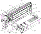
Fig. 1 is a schematic overall structure diagram of an embodiment of the cutting and welding integrated equipment provided by the invention.
Fig. 2 is a schematic structural diagram of the first feeding mechanism or the second feeding mechanism in the integrated cutting and welding device shown in fig. 1.
Fig. 3 is a side view of the integrated cut-and-weld apparatus shown in fig. 1.
Fig. 4 is a schematic view of the internal structure of the first splicing mechanism and the second splicing mechanism in the cutting and welding integrated device shown in fig. 1.
Fig. 5 is a schematic structural diagram of a positioning assembly in the integrated cutting and welding apparatus shown in fig. 1.
Fig. 6 is a top view of the integrated cut-and-weld apparatus shown in fig. 1.
Fig. 7 is an enlarged schematic view at B in fig. 6.
Fig. 8 is an enlarged schematic view of a portion a of fig. 1.
10, a first splicing mechanism; 11. cutting and welding the table; 12. a positioning assembly; 121. positioning pins; 122. a positioning arm; 123. a rotary drive assembly; 20. a first hold-down mechanism; 21. a pressing frame; 22. a compression drive element; 23. a pressing arm; 24. a compression block; 25. a delivery channel; 26. a compression plate; 30. a first feeding mechanism; 31. a feeding table; 32. a clamping jaw; 33. a feed drive assembly; 34. adjustable ground feet; 35. a universal roller; 36. an X-axis slit; 37. a side positioning assembly; 38. a side push assembly; 381. a side push drive element; 382. a side push arm; 383. laterally pushing the roller; 39. a Y-axis chute; 40. a second splicing mechanism; 50. a second hold-down mechanism; 60. a second feeding mechanism; 70. a cutting and welding mechanism; 71. a mounting frame; 72. a drive platform; 721. a Y-axis motion module; 722. an X-axis cutting motion module; 723. a Z-axis cutting motion module; 724. an X-axis welding motion module; 725. a Z-axis welding motion module; 73. a cutting head; 74. welding a head; 80. splicing the driving components; 90. a limiting component; 100. a plate material; 200. a base.
Detailed Description
In order to make the objects, technical solutions and effects of the present invention clearer and clearer, the present invention is further described in detail below with reference to the accompanying drawings and examples. It is to be understood that the specific embodiments described herein are merely illustrative of the invention and are not intended to limit the invention, which is not further described, and that elements, structures and features of one embodiment may be beneficially incorporated in other embodiments.
In the description of the present invention, it should be noted that the terms "upper", "lower", "bottom", "inner", and the like indicate orientations or positional relationships based on the orientations or positional relationships shown in the drawings, and are only for convenience in describing the present invention and simplifying the description, but do not indicate or imply that the referred device or element must have a specific orientation, be constructed in a specific orientation, and be operated, and thus, should not be construed as limiting the present invention.
In the description of the present invention, it is to be noted that, unless otherwise explicitly specified or limited, the terms "connected" and "connected" are to be interpreted broadly, e.g., as being fixed or detachable or integrally connected; they may be connected directly or indirectly through intervening media, or they may be interconnected between two elements. The specific meanings of the above terms in the present invention can be understood in specific cases to those skilled in the art.
Referring to fig. 1, an overall structure diagram of an embodiment of a cutting and welding integrated device provided in the present invention is shown, the cutting and welding integrated device in the embodiment includes: the splicing device comprises a first splicing mechanism 10, a first pressing mechanism 20, a first feeding mechanism 30, a second splicing mechanism 40, a second pressing mechanism 50, a second feeding mechanism 60 and a cutting and welding mechanism 70.
The first splicing mechanism 10 and the second splicing mechanism 40 are arranged oppositely and are respectively used for bearing two different plates 100; the first pressing mechanism 20 is arranged on the first splicing mechanism 10 and used for pressing the plate materials 100; the first feeding mechanism 30 is positioned at the outer side of the first splicing mechanism 10 and used for feeding the plate 100 into the first splicing mechanism 10; the second pressing mechanism 50 is arranged on the second splicing mechanism 40 and used for pressing another plate material 100; the second feeding mechanism 60 is located at the outer side of the second splicing mechanism 40 and is used for feeding another plate material 100 into the second splicing mechanism 40; the cutting and welding mechanism 70 is arranged at the side of the first splicing mechanism 10 and the second splicing mechanism 40 and used for cutting and welding the plate 100.
During processing, the two sheets of sheet materials 100 are respectively placed on the first feeding mechanism 30 and the second feeding mechanism 60 through a manual or automatic auxiliary tool, and are respectively sent to the first splicing mechanism 10 and the second splicing mechanism 40 through the first feeding mechanism 30 and the second feeding mechanism 60, and then are respectively compressed through the first compressing mechanism 20 and the second compressing mechanism 50. At this time, the cutting and welding mechanism 70 cuts light, and the front end edges of the two sheet materials 100 are cut orderly; after the cutting is finished, the first splicing mechanism 10 and the second splicing mechanism 40 move oppositely to splice the two plates 100; after splicing, the cutting and welding mechanism 70 performs light welding to weld the two sheets 100 together, and the welded sheet 100 is pulled out by the first feeding mechanism 30 and/or the second feeding mechanism 60.
In addition, the plate material 100 may not be pressed by the first pressing assembly 20 and the second pressing assembly 50, and the plate material 100 may be fixed on the first splicing mechanism 10 and the second splicing mechanism 40 by the self weight of the plate material 100, or the plate material 100 may be fixed by other side pressing and clamping manners, which is not limited in the present invention.
Referring to fig. 2, in an embodiment, taking the first feeding mechanism 30 as an example, it includes a feeding table 31, a clamping jaw 32 and a feeding driving assembly 33, where the feeding table 31 is used for placing the sheet material 100; the clamping jaw 32 is connected with the feeding table 31 in a sliding manner and is used for clamping the plate 100; the feeding driving assembly 33 is arranged on the feeding table 31 and used for driving the clamping jaws 32 to move towards the corresponding first splicing mechanism 10 or the corresponding second splicing mechanism 40.
Wherein, the feeding table 31 is supported by an adjustable foot 34, so that the feeding table 31 can be adjusted in height. The feeding table 31 is uniformly provided with universal rollers 35, so that the sheet material 100 can easily slide freely along all directions after being placed on the table top, and the surface of the sheet material 100 can not be scratched. The jaws 32 may be pneumatically, hydraulically, or electrically actuated to grip/release the sheet material 100. An X-axis slit 36 is formed in the feeding table 31, the clamping jaws 32 can slide in the X-axis slit 36, the feeding driving assembly 33 is arranged at the bottom of the X-axis slit 36, and a sliding block of the feeding driving assembly 33 is fixedly connected with the clamping jaws 32, so that the clamping jaws 32 can be driven to move along the X-axis direction, and the plate 100 is fed into the first splicing mechanism 10.
The number of the jaws 32 may be provided as one pair for stably holding and moving the sheet 100, and may be provided as a plurality of pairs. The feeding driving assembly 33 is preferably a linear motion module, or may be driven by pneumatic, hydraulic or other electric means, which is not limited in the present invention.
Further, the first feeding mechanism 30 and the second feeding mechanism 60 are also used to perform the side positioning of the sheet 100 when feeding. Taking the first feeding mechanism 30 as an example, the first feeding mechanism further includes a side positioning component 37 and a side pushing component 38, the side positioning component 37 is located at one side of the feeding table 31 and is used for positioning the side of the sheet material 100, and the side pushing component 38 is located at the other side of the feeding table 31 and is used for pushing the sheet material 100 to the side positioning component 37.
The side positioning assembly 37 is arranged on the table top at one side of the feeding table 31, and comprises a row of side positioning rollers arranged along the X-axis direction, so that the positioning function can be achieved, and the edge of the sheet material 100 contacting with the side positioning rollers can not be scratched when the sheet material 100 is pushed.
The side push assembly 38 includes a side push drive element 381, a side push arm 382, and a plurality of side push rollers 383, the plurality of side push rollers 383 being disposed on the side push arm 382, the side push arm 382 being disposed at a drive end of the side push drive element 381. The feeding table 31 is provided with a plurality of Y-axis sliding grooves 39 corresponding to the plurality of side pushing rollers 383 on the other side table surface, so that when the side pushing driving element 381 drives the side pushing arms 382 to move, each side pushing roller 383 can slide in the corresponding Y-axis sliding groove 39, thereby abutting against the edge of the plate material 100 and pushing the plate material 100 to the side positioning rollers. The side pushing driving assembly is preferably a linear motion module, or may be driven by pneumatic, hydraulic or other electric means, which is not limited in the present invention.
When the first feeding mechanism 30 works, firstly, the sheet material 100 is placed on the feeding table 31, and the side push driving element 381 pushes the sheet material 100 to move along the Y-axis direction through the side push arm 382 and the side push roller 383, so that the sheet material 100 abuts against the side positioning roller, and the side positioning of the sheet material 100 is completed; then the clamping jaws 32 clamp the rear end edge of the sheet material 100, and push the sheet material 100 to move in the X-axis direction, so as to push the sheet material 100 into the first splicing mechanism 10. Similarly, the second feeding mechanism 60 may adopt the same structure and feeding manner as the first feeding mechanism 30, and of course, other structures may also be adopted to realize the feeding and positioning functions, which is not limited in the present invention.
Referring to fig. 3 and 4, in order to realize the opposite movement of the first splicing mechanism 10 and the second splicing mechanism 40, the cutting and welding integrated apparatus further includes a base 200 and a splicing driving assembly 80. Second splicing mechanism 40 and base 200 fixed connection, first splicing mechanism 10 and base 200 sliding connection, concatenation drive assembly 80 set up on the base 200 for promote first splicing mechanism 10 and be close to or keep away from second splicing mechanism 40.
Wherein, the base 200 can also be supported by adjustable feet 34, so that the height of the base 200 can be adjusted. And, the base 200 can be provided with a limiting component 90, when the splicing driving component 80 pushes the first splicing mechanism 10 to slide from one side, the limiting component 90 can limit the sliding of the first splicing mechanism 10 from the other side, so as to prevent the first splicing mechanism 10 from sliding over the travel and damaging the plate 100 or equipment. The splice drive assembly 80 is preferably a cylinder assembly, although other drive means, such as hydraulic or electric, may be used, and the invention is not limited thereto.
Referring to fig. 4, in a specific embodiment, taking the first splicing mechanism 10 as an example, the first splicing mechanism includes a cutting and welding table 11 and a positioning assembly 12, where the cutting and welding table 11 is used for placing the sheet material 100, and the positioning assembly 12 is disposed on the cutting and welding table 11 and is used for positioning an end portion of the sheet material 100 and releasing the positioning of the end portion of the sheet material after the positioning is completed. After the positioning of the sheet material 100 is completed, the first pressing mechanism 20 presses the sheet material 100, and then the cutting and welding mechanism 70 performs accurate cutting and welding on the sheet material 100.
The positioning assembly 12 is used to position the sheet material 100 before the sheet material 100 is processed. And the positioning state of the positioning component 12 can be released, so that the positioning component 12 deviates from the sheet material 100 when the sheet material 100 is processed, and the positioning component 12 is prevented from being damaged due to the fact that laser contacts the positioning component 12 during processing. Further, referring to fig. 4 and 5, the positioning assembly 12 includes a positioning pin 121, a positioning arm 122 and a rotation driving assembly 123, wherein the positioning pin 121 is disposed on the positioning arm 122 and is used for blocking the slab 100 at a preset positioning position; the positioning arm 122 is disposed at the drive end of the rotary drive assembly 123; the rotation driving assembly 123 is disposed on the cutting and welding table 11, and is configured to drive the positioning arm 122 and the positioning pin 121 to rotate, so that the positioning pin 121 is located at a preset positioning position or deviates from the preset positioning position.
The rotation driving assembly 123 may include a positioning cylinder, a connecting rod, and a rotation shaft. The positioning cylinder is fixed below the table surface of the cutting and welding table 11, and an output rod of the positioning cylinder is rotatably connected with one end of the connecting rod; the rotating shaft is also arranged below the table top of the cutting and welding table 11 through a fixed seat and is rotationally connected with the fixed seat; one end of the positioning arm 122 is fixed to the rotation shaft, and the other end of the link is also fixed to the rotation shaft. When the positioning cylinder output rod moves linearly, the connecting rod can drive the positioning arm 122 and the rotating shaft to rotate, so that the rotating shaft drives the positioning arm 122 and the positioning pin 121 to rotate.
When the positioning pin 121 of the second splicing mechanism 40 rotates clockwise to expose the table surface of the cutting and welding table 11, and the positioning pin 121 is perpendicular to the table surface of the cutting and welding table 11, the position is the preset positioning position where the positioning pin 121 blocks the sheet material 100. After the sheet material 100 touches the positioning pin 121, the second feeding mechanism 60 stops driving the sheet material 100, and the second pressing mechanism 50 presses the sheet material 100. Before the cutting and welding mechanism 70 cuts or welds the sheet material 100, the rotation driving assembly 123 drives the positioning pin 121 to rotate to the lower side of the cutting and welding table 11 along the counterclockwise direction, so that the positioning pin is kept away from the direct laser irradiation area, and the sheet material is prevented from being punctured or burnt during cutting or welding.
Similarly, the first splicing mechanism 10 may adopt the same structure as the second splicing mechanism 40, and certainly, other structures may also be adopted to achieve the positioning and splicing of the plate 100, which is not limited in the present invention. In addition, please refer to fig. 5, fig. 6 and fig. 7, the number of the positioning pins 121 of the first splicing mechanism 10 and the second splicing mechanism 40 is multiple, and the different positioning pins 121 of the first splicing mechanism 10 and the second splicing mechanism 40 are staggered, so as to avoid collision and interference of the different positioning pins 121 in the rotation process.
With continued reference to fig. 3 and 4, in an exemplary embodiment, the first pressing mechanism 20 includes a pressing frame 21, a pressing driving element 22, a pressing arm 23, and a pressing block 24. The pressing frame 21 is arranged on the first splicing mechanism 10; the pressing driving element 22 is arranged on the pressing frame 21; the pressing arm 23 is arranged at the driving end of the pressing driving element 22; the pressing block 24 is provided on the pressing arm 23 for pressing the sheet material 100 under the driving of the pressing driving element 22.
The pressing frame 21 is arranged on the cutting and welding table 11, a conveying channel 25 is formed between the pressing frame 21 and the cutting and welding table 11, and the first feeding mechanism 30 feeds the plate 100 into the first splicing mechanism 10 through the conveying channel 25. The pressing driving element 22 can be an air cylinder, a hydraulic cylinder, an electric cylinder or other driving modes, an output rod of the pressing driving element 22 is fixedly connected with the pressing arm 23, and the pressing arm 23 extends out of the pressing frame 21 and is fixedly connected with the pressing block 24. Moreover, the pressing plates 26 along the Y-axis direction may be disposed between the pressing arms 23 and the pressing blocks 24, and referring to fig. 5 and fig. 6, a plurality of pressing blocks 24 are uniformly arranged below the pressing plates 26, so that the pressing blocks 24 can more uniformly press the sheet material 100, and the situations of edge warp deformation during cutting, cutting edge deviation during cutting, sheet material 100 deformation during welding, and the like of the sheet material 100 can be avoided.
Similarly, the second pressing mechanism 50 may have the same structure as the first pressing mechanism 20, and of course, other structures may be adopted to press the sheet material 100, which is not limited in the present invention.
Referring to fig. 1 and 8, the cutting and welding mechanism 70 includes a mounting frame 71, a driving platform 72, a cutting head 73, and a welding head 74. The mounting rack 71 is arranged on the base 200 and comprises upright columns positioned at two sides of the first splicing mechanism 10 and the second splicing mechanism 40 and a cross beam carried in the middle of the upright columns at two sides; the cutting head 73 and the welding head 74 are both arranged at the driving end of the driving platform 72; the driving platform 72 is disposed on the mounting frame 71 and above the first splicing mechanism 10 and the second splicing mechanism 40, and is used for driving the cutting head 73 and the welding head 74 to move.
Wherein the cutting head 73 and the welding head 74 are preferably a laser cutting head and a laser welding head. The laser cutting has the advantages of high precision, high speed and small heat influence, and can improve the cutting quality and the cutting efficiency of the plate 100. The laser welding has the advantages of high speed, large depth and small deformation, and can improve the welding quality and the welding efficiency of the plate 100. Of course, the laser cutting head 73 and the laser welding head 74 may be a single laser processing head, and laser cutting and laser welding may be performed by changing laser parameters.
The driving platform 72 comprises a Y-axis motion module 721, an X-axis cutting motion module 722, a Z-axis cutting motion module 723, an X-axis welding motion module 724 and a Z-axis welding motion module 725; the X-axis cutting motion module 722 and the X-axis welding motion module 724 are arranged at the driving end of the Y-axis motion module 721, that is, the Y-axis motion module 721 drives two sides of the slide; the Z-axis cutting motion module 723 is arranged at the driving end of the X-axis cutting motion module 722, and the cutting head 73 is arranged at the driving end of the Z-axis cutting motion module 723; the Z-axis welding motion module 725 is disposed at the driving end of the X-axis welding motion module 724, and the welding head 74 is disposed at the driving end of the Z-axis welding motion module 725.
The Y-axis motion module 721, the X-axis cutting motion module 722, the Z-axis cutting motion module 723, the X-axis welding motion module 724, and the Z-axis welding motion module 725 may be driven by a linear module, or may be driven by other methods, so that the cutting head 73 and the welding head 74 may move along the X-axis, the Y-axis, and the Z-axis directions, and then align to the sheet 100 to be cut or welded to perform a cutting operation or a welding operation.
Therefore, through the mutual cooperation among the first splicing mechanism 10, the first pressing mechanism 20, the first feeding mechanism 30, the second splicing mechanism 40, the second pressing mechanism 50, the second feeding mechanism 60 and the cutting and welding mechanism 70, the automatic positioning, the automatic pressing, the automatic cutting, the automatic splicing and the automatic welding of two plates 100 to be tailor-welded on a cutting and welding integrated device can be realized, the laser cutting and the laser tailor-welding of the plates 100 can be continuously completed, the use of a single special cutting machine, a single special welding machine or various clamps is avoided, the integration level of the clamps and the devices is improved, the cost and the occupied area are reduced, and the processing efficiency is improved.
It should be understood that equivalents and modifications of the technical solution and inventive concept thereof may occur to those skilled in the art, and all such modifications and alterations should fall within the scope of the appended claims.
Claims (10)
1. A cut-and-weld integrated apparatus, comprising:
the first splicing mechanism is used for bearing the plate;
the first feeding mechanism is positioned on the outer side of the first splicing mechanism and used for feeding the plate materials into the first splicing mechanism;
the second splicing mechanism is arranged opposite to the first splicing mechanism and used for bearing another plate, and the first splicing mechanism and the second splicing mechanism can move oppositely;
the second feeding mechanism is positioned on the outer side of the second splicing mechanism and used for feeding the other plate material into the second splicing mechanism; and
and the cutting and welding mechanism is used for cutting and welding the plate.
2. The cutting and welding integrated equipment according to claim 1, wherein the first splicing mechanism and/or the second splicing mechanism comprises a cutting and welding table and a positioning assembly, the cutting and welding table is used for placing the plate, and the positioning assembly is arranged on the cutting and welding table and used for positioning the end part of the plate and removing the positioning of the end part of the plate after the positioning is completed.
3. The cut-and-weld integrated equipment according to claim 2, wherein the positioning assembly comprises a positioning pin, a positioning arm and a rotary driving assembly, the positioning pin is arranged on the positioning arm and used for blocking a plate material at a preset positioning position, the positioning arm is arranged at a driving end of the rotary driving assembly, and the rotary driving assembly is arranged on the cut-and-weld table and used for driving the positioning arm and the positioning pin to rotate so that the positioning pin is at the preset positioning position or deviates from the preset positioning position.
4. The cut-and-weld integrated equipment according to claim 3, wherein the number of the positioning pins is multiple, and different positioning pins of the first splicing mechanism and the second splicing mechanism are arranged in a staggered mode.
5. The cut-weld integrated equipment as claimed in claim 1, further comprising a base and a splicing driving assembly, wherein the second splicing mechanism is fixedly connected with the base, the first splicing mechanism is slidably connected with the base, and the splicing driving assembly is arranged on the base and used for pushing the first splicing mechanism to approach or be far away from the second splicing mechanism.
6. The cut-and-weld integrated equipment according to any one of claims 1 to 5, further comprising a first pressing mechanism and a second pressing assembly, wherein the first pressing mechanism is arranged on the first splicing mechanism and used for pressing a plate, and the second pressing mechanism is arranged on the second splicing mechanism and used for pressing another plate.
7. The cut-and-weld integrated apparatus of claim 6, wherein the first hold-down mechanism and/or the second hold-down assembly comprises:
the pressing frame is arranged on the corresponding first splicing mechanism or the second splicing mechanism;
the pressing driving element is arranged on the pressing frame;
the pressing arm is arranged at the driving end of the pressing driving element; and
and the pressing block is arranged on the pressing arm and used for pressing the plate under the driving of the pressing driving element.
8. The cut-and-weld integrated apparatus according to claim 1, wherein the first feeding mechanism and/or the second feeding mechanism includes:
the feeding table is used for placing the plate;
the clamping jaw is connected with the feeding table in a sliding mode and used for clamping the plate; and
and the feeding driving assembly is arranged on the feeding table and used for driving the clamping jaws to move towards the corresponding first splicing mechanism or the second splicing mechanism.
9. The cut-and-weld integrated equipment according to claim 8, wherein the first feeding mechanism and/or the second feeding mechanism further comprises a side positioning component and a side pushing component, the side positioning component is located on one side of the feeding table and used for positioning the side of the sheet, and the side pushing component is located on the other side of the feeding table and used for pushing the sheet to the side positioning component.
10. The cut-and-weld integrated equipment according to claim 1, wherein the cut-and-weld mechanism comprises a mounting frame, a driving platform, a cutting head and a welding head, the cutting head and the welding head are both arranged at a driving end of the driving platform, and the driving platform is arranged on the mounting frame and is used for driving the cutting head or the welding head to process the plate.
Priority Applications (1)
| Application Number | Priority Date | Filing Date | Title |
|---|---|---|---|
| CN202110738118.4A CN113601013A (en) | 2021-06-30 | 2021-06-30 | Cutting and welding integrated equipment |
Applications Claiming Priority (1)
| Application Number | Priority Date | Filing Date | Title |
|---|---|---|---|
| CN202110738118.4A CN113601013A (en) | 2021-06-30 | 2021-06-30 | Cutting and welding integrated equipment |
Publications (1)
| Publication Number | Publication Date |
|---|---|
| CN113601013A true CN113601013A (en) | 2021-11-05 |
Family
ID=78337038
Family Applications (1)
| Application Number | Title | Priority Date | Filing Date |
|---|---|---|---|
| CN202110738118.4A Pending CN113601013A (en) | 2021-06-30 | 2021-06-30 | Cutting and welding integrated equipment |
Country Status (1)
| Country | Link |
|---|---|
| CN (1) | CN113601013A (en) |
Cited By (2)
| Publication number | Priority date | Publication date | Assignee | Title |
|---|---|---|---|---|
| CN113927184A (en) * | 2021-12-01 | 2022-01-14 | 广东宏石激光技术股份有限公司 | Laser cutting device and control method |
| CN117066738A (en) * | 2023-10-17 | 2023-11-17 | 江苏迈冠体育产业有限公司 | Laser cutting welding intelligent production line for stand seat armrests |
Citations (6)
| Publication number | Priority date | Publication date | Assignee | Title |
|---|---|---|---|---|
| CN108568609A (en) * | 2018-06-01 | 2018-09-25 | 梅塞尔切割焊接(中国)有限公司 | The full-automatic loading and unloading laser high efficiency cutting system of mirror face stainless steel thin plate |
| CN110281025A (en) * | 2019-07-22 | 2019-09-27 | 深圳市思博威激光科技有限公司 | A kind of Full-automatic laser welding machine |
| CN110340671A (en) * | 2019-07-30 | 2019-10-18 | 华工法利莱切焊系统工程有限公司 | Integrated plate cuts soldering equipment automatically |
| US20190358742A1 (en) * | 2017-01-23 | 2019-11-28 | Kun Shan Theta Micro Co., Ltd | Automatic step steel plate cutting and welding device, and method thereof |
| CN112077442A (en) * | 2020-09-03 | 2020-12-15 | 武汉中车电牵科技有限公司 | Rail vehicle wall laser assembly welding process and production layout structure thereof |
| CN112658516A (en) * | 2020-12-28 | 2021-04-16 | 厦门华谱科技有限公司 | Multi-station multi-material-level bracket connecting piece production line |
-
2021
- 2021-06-30 CN CN202110738118.4A patent/CN113601013A/en active Pending
Patent Citations (6)
| Publication number | Priority date | Publication date | Assignee | Title |
|---|---|---|---|---|
| US20190358742A1 (en) * | 2017-01-23 | 2019-11-28 | Kun Shan Theta Micro Co., Ltd | Automatic step steel plate cutting and welding device, and method thereof |
| CN108568609A (en) * | 2018-06-01 | 2018-09-25 | 梅塞尔切割焊接(中国)有限公司 | The full-automatic loading and unloading laser high efficiency cutting system of mirror face stainless steel thin plate |
| CN110281025A (en) * | 2019-07-22 | 2019-09-27 | 深圳市思博威激光科技有限公司 | A kind of Full-automatic laser welding machine |
| CN110340671A (en) * | 2019-07-30 | 2019-10-18 | 华工法利莱切焊系统工程有限公司 | Integrated plate cuts soldering equipment automatically |
| CN112077442A (en) * | 2020-09-03 | 2020-12-15 | 武汉中车电牵科技有限公司 | Rail vehicle wall laser assembly welding process and production layout structure thereof |
| CN112658516A (en) * | 2020-12-28 | 2021-04-16 | 厦门华谱科技有限公司 | Multi-station multi-material-level bracket connecting piece production line |
Cited By (3)
| Publication number | Priority date | Publication date | Assignee | Title |
|---|---|---|---|---|
| CN113927184A (en) * | 2021-12-01 | 2022-01-14 | 广东宏石激光技术股份有限公司 | Laser cutting device and control method |
| CN117066738A (en) * | 2023-10-17 | 2023-11-17 | 江苏迈冠体育产业有限公司 | Laser cutting welding intelligent production line for stand seat armrests |
| CN117066738B (en) * | 2023-10-17 | 2023-12-19 | 江苏迈冠体育产业有限公司 | Laser cutting welding intelligent production line for stand seat armrests |
Similar Documents
| Publication | Publication Date | Title |
|---|---|---|
| JP3188090U (en) | Tube chamfering equipment | |
| CN113601013A (en) | Cutting and welding integrated equipment | |
| KR101621064B1 (en) | Automatic punching and noching apparatus of Profile | |
| KR101537757B1 (en) | Piercing system | |
| KR100715422B1 (en) | Multi-step process press system | |
| CN113681157A (en) | Automatic cutting and welding equipment and cutting and welding method | |
| CN211614466U (en) | Plate shearing machine capable of effectively improving machining precision | |
| CN115070540B (en) | Cutting rule inclined plane grinding machine tool | |
| CN215032568U (en) | High-efficient bender of panel | |
| CN215970174U (en) | Feeding structure of edge bonding machine for hollow plate | |
| CN110788169B (en) | Bending process and bending equipment for elevator sill | |
| CN110977480A (en) | Cutting and milling combined sawing machine capable of receiving materials | |
| CN210878096U (en) | Forward welding and side welding laser welding machine | |
| CN219098024U (en) | Feeding magnetic sheet clamping mechanism | |
| JP3447373B2 (en) | Work unloading device of plate processing machine | |
| JP4841045B2 (en) | Method and apparatus for unloading work in cutting machine | |
| JP4412961B2 (en) | Welding system and welding method | |
| CN216576575U (en) | Assembly production line | |
| CN219425952U (en) | Steel plate dividing device | |
| CN218363264U (en) | Automatic realize two kinds of tablet paster welded equipment | |
| WO2024066761A1 (en) | Punching guiding and positioning apparatus for punch press | |
| CN212823853U (en) | Cutting and milling combined sawing machine capable of receiving materials | |
| JPH1128528A (en) | Method for carrying-in work in punching press and device therefor | |
| CN214759376U (en) | Novel automatic processing assembly line of gauze mask | |
| JP2000015366A (en) | Plate stock feeding and working system |
Legal Events
| Date | Code | Title | Description |
|---|---|---|---|
| PB01 | Publication | ||
| PB01 | Publication | ||
| SE01 | Entry into force of request for substantive examination | ||
| SE01 | Entry into force of request for substantive examination | ||
| RJ01 | Rejection of invention patent application after publication | ||
| RJ01 | Rejection of invention patent application after publication |
Application publication date: 20211105 |