CN106999740B - Wearable device for delivering air - Google Patents
Wearable device for delivering air Download PDFInfo
- Publication number
- CN106999740B CN106999740B CN201580064966.4A CN201580064966A CN106999740B CN 106999740 B CN106999740 B CN 106999740B CN 201580064966 A CN201580064966 A CN 201580064966A CN 106999740 B CN106999740 B CN 106999740B
- Authority
- CN
- China
- Prior art keywords
- air
- user
- controller
- airflow
- entertainment
- Prior art date
- Legal status (The legal status is an assumption and is not a legal conclusion. Google has not performed a legal analysis and makes no representation as to the accuracy of the status listed.)
- Active
Links
Images


Classifications
-
- A—HUMAN NECESSITIES
- A62—LIFE-SAVING; FIRE-FIGHTING
- A62B—DEVICES, APPARATUS OR METHODS FOR LIFE-SAVING
- A62B18/00—Breathing masks or helmets, e.g. affording protection against chemical agents or for use at high altitudes or incorporating a pump or compressor for reducing the inhalation effort
- A62B18/003—Breathing masks or helmets, e.g. affording protection against chemical agents or for use at high altitudes or incorporating a pump or compressor for reducing the inhalation effort having means for creating a fresh air curtain
-
- A—HUMAN NECESSITIES
- A41—WEARING APPAREL
- A41B—SHIRTS; UNDERWEAR; BABY LINEN; HANDKERCHIEFS
- A41B1/00—Shirts
-
- A—HUMAN NECESSITIES
- A41—WEARING APPAREL
- A41B—SHIRTS; UNDERWEAR; BABY LINEN; HANDKERCHIEFS
- A41B3/00—Collars
-
- A—HUMAN NECESSITIES
- A41—WEARING APPAREL
- A41D—OUTERWEAR; PROTECTIVE GARMENTS; ACCESSORIES
- A41D20/00—Wristbands or headbands, e.g. for absorbing sweat
-
- A—HUMAN NECESSITIES
- A41—WEARING APPAREL
- A41D—OUTERWEAR; PROTECTIVE GARMENTS; ACCESSORIES
- A41D23/00—Scarves; Head-scarves; Neckerchiefs
-
- A—HUMAN NECESSITIES
- A42—HEADWEAR
- A42B—HATS; HEAD COVERINGS
- A42B1/00—Hats; Caps; Hoods
- A42B1/006—Hats; Caps; Hoods convertible or adaptable for uses other than as headgear
-
- A—HUMAN NECESSITIES
- A44—HABERDASHERY; JEWELLERY
- A44C—PERSONAL ADORNMENTS, e.g. JEWELLERY; COINS
- A44C5/00—Bracelets; Wrist-watch straps; Fastenings for bracelets or wrist-watch straps
- A44C5/0007—Bracelets specially adapted for other functions or with means for attaching other articles
- A44C5/0023—Bracelets specially adapted for other functions or with means for attaching other articles for therapeutic purposes
-
- A—HUMAN NECESSITIES
- A61—MEDICAL OR VETERINARY SCIENCE; HYGIENE
- A61F—FILTERS IMPLANTABLE INTO BLOOD VESSELS; PROSTHESES; DEVICES PROVIDING PATENCY TO, OR PREVENTING COLLAPSING OF, TUBULAR STRUCTURES OF THE BODY, e.g. STENTS; ORTHOPAEDIC, NURSING OR CONTRACEPTIVE DEVICES; FOMENTATION; TREATMENT OR PROTECTION OF EYES OR EARS; BANDAGES, DRESSINGS OR ABSORBENT PADS; FIRST-AID KITS
- A61F9/00—Methods or devices for treatment of the eyes; Devices for putting-in contact lenses; Devices to correct squinting; Apparatus to guide the blind; Protective devices for the eyes, carried on the body or in the hand
- A61F9/02—Goggles
- A61F9/028—Ventilation means
-
- A—HUMAN NECESSITIES
- A61—MEDICAL OR VETERINARY SCIENCE; HYGIENE
- A61F—FILTERS IMPLANTABLE INTO BLOOD VESSELS; PROSTHESES; DEVICES PROVIDING PATENCY TO, OR PREVENTING COLLAPSING OF, TUBULAR STRUCTURES OF THE BODY, e.g. STENTS; ORTHOPAEDIC, NURSING OR CONTRACEPTIVE DEVICES; FOMENTATION; TREATMENT OR PROTECTION OF EYES OR EARS; BANDAGES, DRESSINGS OR ABSORBENT PADS; FIRST-AID KITS
- A61F9/00—Methods or devices for treatment of the eyes; Devices for putting-in contact lenses; Devices to correct squinting; Apparatus to guide the blind; Protective devices for the eyes, carried on the body or in the hand
- A61F9/04—Eye-masks ; Devices to be worn on the face, not intended for looking through; Eye-pads for sunbathing
- A61F9/045—Eye-shades or visors; Shields beside, between or below the eyes
-
- A—HUMAN NECESSITIES
- A61—MEDICAL OR VETERINARY SCIENCE; HYGIENE
- A61M—DEVICES FOR INTRODUCING MEDIA INTO, OR ONTO, THE BODY; DEVICES FOR TRANSDUCING BODY MEDIA OR FOR TAKING MEDIA FROM THE BODY; DEVICES FOR PRODUCING OR ENDING SLEEP OR STUPOR
- A61M16/00—Devices for influencing the respiratory system of patients by gas treatment, e.g. mouth-to-mouth respiration; Tracheal tubes
- A61M16/0057—Pumps therefor
- A61M16/0066—Blowers or centrifugal pumps
- A61M16/0069—Blowers or centrifugal pumps the speed thereof being controlled by respiratory parameters, e.g. by inhalation
-
- A—HUMAN NECESSITIES
- A61—MEDICAL OR VETERINARY SCIENCE; HYGIENE
- A61M—DEVICES FOR INTRODUCING MEDIA INTO, OR ONTO, THE BODY; DEVICES FOR TRANSDUCING BODY MEDIA OR FOR TAKING MEDIA FROM THE BODY; DEVICES FOR PRODUCING OR ENDING SLEEP OR STUPOR
- A61M16/00—Devices for influencing the respiratory system of patients by gas treatment, e.g. mouth-to-mouth respiration; Tracheal tubes
- A61M16/06—Respiratory or anaesthetic masks
- A61M16/0666—Nasal cannulas or tubing
- A61M16/0672—Nasal cannula assemblies for oxygen therapy
-
- A—HUMAN NECESSITIES
- A61—MEDICAL OR VETERINARY SCIENCE; HYGIENE
- A61M—DEVICES FOR INTRODUCING MEDIA INTO, OR ONTO, THE BODY; DEVICES FOR TRANSDUCING BODY MEDIA OR FOR TAKING MEDIA FROM THE BODY; DEVICES FOR PRODUCING OR ENDING SLEEP OR STUPOR
- A61M16/00—Devices for influencing the respiratory system of patients by gas treatment, e.g. mouth-to-mouth respiration; Tracheal tubes
- A61M16/08—Bellows; Connecting tubes ; Water traps; Patient circuits
- A61M16/0875—Connecting tubes
-
- A—HUMAN NECESSITIES
- A61—MEDICAL OR VETERINARY SCIENCE; HYGIENE
- A61M—DEVICES FOR INTRODUCING MEDIA INTO, OR ONTO, THE BODY; DEVICES FOR TRANSDUCING BODY MEDIA OR FOR TAKING MEDIA FROM THE BODY; DEVICES FOR PRODUCING OR ENDING SLEEP OR STUPOR
- A61M16/00—Devices for influencing the respiratory system of patients by gas treatment, e.g. mouth-to-mouth respiration; Tracheal tubes
- A61M16/10—Preparation of respiratory gases or vapours
- A61M16/105—Filters
- A61M16/1055—Filters bacterial
-
- A—HUMAN NECESSITIES
- A61—MEDICAL OR VETERINARY SCIENCE; HYGIENE
- A61M—DEVICES FOR INTRODUCING MEDIA INTO, OR ONTO, THE BODY; DEVICES FOR TRANSDUCING BODY MEDIA OR FOR TAKING MEDIA FROM THE BODY; DEVICES FOR PRODUCING OR ENDING SLEEP OR STUPOR
- A61M16/00—Devices for influencing the respiratory system of patients by gas treatment, e.g. mouth-to-mouth respiration; Tracheal tubes
- A61M16/10—Preparation of respiratory gases or vapours
- A61M16/105—Filters
- A61M16/106—Filters in a path
- A61M16/107—Filters in a path in the inspiratory path
-
- A—HUMAN NECESSITIES
- A61—MEDICAL OR VETERINARY SCIENCE; HYGIENE
- A61M—DEVICES FOR INTRODUCING MEDIA INTO, OR ONTO, THE BODY; DEVICES FOR TRANSDUCING BODY MEDIA OR FOR TAKING MEDIA FROM THE BODY; DEVICES FOR PRODUCING OR ENDING SLEEP OR STUPOR
- A61M16/00—Devices for influencing the respiratory system of patients by gas treatment, e.g. mouth-to-mouth respiration; Tracheal tubes
- A61M16/10—Preparation of respiratory gases or vapours
- A61M16/1075—Preparation of respiratory gases or vapours by influencing the temperature
-
- A—HUMAN NECESSITIES
- A61—MEDICAL OR VETERINARY SCIENCE; HYGIENE
- A61M—DEVICES FOR INTRODUCING MEDIA INTO, OR ONTO, THE BODY; DEVICES FOR TRANSDUCING BODY MEDIA OR FOR TAKING MEDIA FROM THE BODY; DEVICES FOR PRODUCING OR ENDING SLEEP OR STUPOR
- A61M16/00—Devices for influencing the respiratory system of patients by gas treatment, e.g. mouth-to-mouth respiration; Tracheal tubes
- A61M16/10—Preparation of respiratory gases or vapours
- A61M16/14—Preparation of respiratory gases or vapours by mixing different fluids, one of them being in a liquid phase
- A61M16/16—Devices to humidify the respiration air
-
- A—HUMAN NECESSITIES
- A61—MEDICAL OR VETERINARY SCIENCE; HYGIENE
- A61M—DEVICES FOR INTRODUCING MEDIA INTO, OR ONTO, THE BODY; DEVICES FOR TRANSDUCING BODY MEDIA OR FOR TAKING MEDIA FROM THE BODY; DEVICES FOR PRODUCING OR ENDING SLEEP OR STUPOR
- A61M21/00—Other devices or methods to cause a change in the state of consciousness; Devices for producing or ending sleep by mechanical, optical, or acoustical means, e.g. for hypnosis
-
- A—HUMAN NECESSITIES
- A62—LIFE-SAVING; FIRE-FIGHTING
- A62B—DEVICES, APPARATUS OR METHODS FOR LIFE-SAVING
- A62B18/00—Breathing masks or helmets, e.g. affording protection against chemical agents or for use at high altitudes or incorporating a pump or compressor for reducing the inhalation effort
- A62B18/006—Breathing masks or helmets, e.g. affording protection against chemical agents or for use at high altitudes or incorporating a pump or compressor for reducing the inhalation effort with pumps for forced ventilation
-
- A—HUMAN NECESSITIES
- A62—LIFE-SAVING; FIRE-FIGHTING
- A62B—DEVICES, APPARATUS OR METHODS FOR LIFE-SAVING
- A62B9/00—Component parts for respiratory or breathing apparatus
- A62B9/06—Mouthpieces; Nose-clips
-
- A—HUMAN NECESSITIES
- A63—SPORTS; GAMES; AMUSEMENTS
- A63B—APPARATUS FOR PHYSICAL TRAINING, GYMNASTICS, SWIMMING, CLIMBING, OR FENCING; BALL GAMES; TRAINING EQUIPMENT
- A63B71/00—Games or sports accessories not covered in groups A63B1/00 - A63B69/00
- A63B71/08—Body-protectors for players or sportsmen, i.e. body-protecting accessories affording protection of body parts against blows or collisions
- A63B71/085—Mouth or teeth protectors
-
- A—HUMAN NECESSITIES
- A63—SPORTS; GAMES; AMUSEMENTS
- A63F—CARD, BOARD, OR ROULETTE GAMES; INDOOR GAMES USING SMALL MOVING PLAYING BODIES; VIDEO GAMES; GAMES NOT OTHERWISE PROVIDED FOR
- A63F13/00—Video games, i.e. games using an electronically generated display having two or more dimensions
- A63F13/25—Output arrangements for video game devices
- A63F13/28—Output arrangements for video game devices responding to control signals received from the game device for affecting ambient conditions, e.g. for vibrating players' seats, activating scent dispensers or affecting temperature or light
-
- A—HUMAN NECESSITIES
- A63—SPORTS; GAMES; AMUSEMENTS
- A63F—CARD, BOARD, OR ROULETTE GAMES; INDOOR GAMES USING SMALL MOVING PLAYING BODIES; VIDEO GAMES; GAMES NOT OTHERWISE PROVIDED FOR
- A63F13/00—Video games, i.e. games using an electronically generated display having two or more dimensions
- A63F13/30—Interconnection arrangements between game servers and game devices; Interconnection arrangements between game devices; Interconnection arrangements between game servers
-
- F—MECHANICAL ENGINEERING; LIGHTING; HEATING; WEAPONS; BLASTING
- F04—POSITIVE - DISPLACEMENT MACHINES FOR LIQUIDS; PUMPS FOR LIQUIDS OR ELASTIC FLUIDS
- F04D—NON-POSITIVE-DISPLACEMENT PUMPS
- F04D19/00—Axial-flow pumps
- F04D19/007—Axial-flow pumps multistage fans
-
- F—MECHANICAL ENGINEERING; LIGHTING; HEATING; WEAPONS; BLASTING
- F04—POSITIVE - DISPLACEMENT MACHINES FOR LIQUIDS; PUMPS FOR LIQUIDS OR ELASTIC FLUIDS
- F04D—NON-POSITIVE-DISPLACEMENT PUMPS
- F04D25/00—Pumping installations or systems
- F04D25/02—Units comprising pumps and their driving means
- F04D25/08—Units comprising pumps and their driving means the working fluid being air, e.g. for ventilation
- F04D25/084—Units comprising pumps and their driving means the working fluid being air, e.g. for ventilation hand fans
-
- A—HUMAN NECESSITIES
- A61—MEDICAL OR VETERINARY SCIENCE; HYGIENE
- A61M—DEVICES FOR INTRODUCING MEDIA INTO, OR ONTO, THE BODY; DEVICES FOR TRANSDUCING BODY MEDIA OR FOR TAKING MEDIA FROM THE BODY; DEVICES FOR PRODUCING OR ENDING SLEEP OR STUPOR
- A61M16/00—Devices for influencing the respiratory system of patients by gas treatment, e.g. mouth-to-mouth respiration; Tracheal tubes
- A61M16/10—Preparation of respiratory gases or vapours
- A61M16/105—Filters
- A61M16/106—Filters in a path
- A61M16/1065—Filters in a path in the expiratory path
-
- A—HUMAN NECESSITIES
- A61—MEDICAL OR VETERINARY SCIENCE; HYGIENE
- A61M—DEVICES FOR INTRODUCING MEDIA INTO, OR ONTO, THE BODY; DEVICES FOR TRANSDUCING BODY MEDIA OR FOR TAKING MEDIA FROM THE BODY; DEVICES FOR PRODUCING OR ENDING SLEEP OR STUPOR
- A61M16/00—Devices for influencing the respiratory system of patients by gas treatment, e.g. mouth-to-mouth respiration; Tracheal tubes
- A61M16/10—Preparation of respiratory gases or vapours
- A61M16/14—Preparation of respiratory gases or vapours by mixing different fluids, one of them being in a liquid phase
- A61M16/16—Devices to humidify the respiration air
- A61M16/161—Devices to humidify the respiration air with means for measuring the humidity
-
- A—HUMAN NECESSITIES
- A61—MEDICAL OR VETERINARY SCIENCE; HYGIENE
- A61M—DEVICES FOR INTRODUCING MEDIA INTO, OR ONTO, THE BODY; DEVICES FOR TRANSDUCING BODY MEDIA OR FOR TAKING MEDIA FROM THE BODY; DEVICES FOR PRODUCING OR ENDING SLEEP OR STUPOR
- A61M16/00—Devices for influencing the respiratory system of patients by gas treatment, e.g. mouth-to-mouth respiration; Tracheal tubes
- A61M16/0003—Accessories therefor, e.g. sensors, vibrators, negative pressure
- A61M2016/003—Accessories therefor, e.g. sensors, vibrators, negative pressure with a flowmeter
- A61M2016/0033—Accessories therefor, e.g. sensors, vibrators, negative pressure with a flowmeter electrical
- A61M2016/0039—Accessories therefor, e.g. sensors, vibrators, negative pressure with a flowmeter electrical in the inspiratory circuit
-
- A—HUMAN NECESSITIES
- A61—MEDICAL OR VETERINARY SCIENCE; HYGIENE
- A61M—DEVICES FOR INTRODUCING MEDIA INTO, OR ONTO, THE BODY; DEVICES FOR TRANSDUCING BODY MEDIA OR FOR TAKING MEDIA FROM THE BODY; DEVICES FOR PRODUCING OR ENDING SLEEP OR STUPOR
- A61M21/00—Other devices or methods to cause a change in the state of consciousness; Devices for producing or ending sleep by mechanical, optical, or acoustical means, e.g. for hypnosis
- A61M2021/0005—Other devices or methods to cause a change in the state of consciousness; Devices for producing or ending sleep by mechanical, optical, or acoustical means, e.g. for hypnosis by the use of a particular sense, or stimulus
- A61M2021/0016—Other devices or methods to cause a change in the state of consciousness; Devices for producing or ending sleep by mechanical, optical, or acoustical means, e.g. for hypnosis by the use of a particular sense, or stimulus by the smell sense
-
- A—HUMAN NECESSITIES
- A61—MEDICAL OR VETERINARY SCIENCE; HYGIENE
- A61M—DEVICES FOR INTRODUCING MEDIA INTO, OR ONTO, THE BODY; DEVICES FOR TRANSDUCING BODY MEDIA OR FOR TAKING MEDIA FROM THE BODY; DEVICES FOR PRODUCING OR ENDING SLEEP OR STUPOR
- A61M2205/00—General characteristics of the apparatus
- A61M2205/35—Communication
- A61M2205/3546—Range
- A61M2205/3561—Range local, e.g. within room or hospital
-
- A—HUMAN NECESSITIES
- A61—MEDICAL OR VETERINARY SCIENCE; HYGIENE
- A61M—DEVICES FOR INTRODUCING MEDIA INTO, OR ONTO, THE BODY; DEVICES FOR TRANSDUCING BODY MEDIA OR FOR TAKING MEDIA FROM THE BODY; DEVICES FOR PRODUCING OR ENDING SLEEP OR STUPOR
- A61M2205/00—General characteristics of the apparatus
- A61M2205/35—Communication
- A61M2205/3576—Communication with non implanted data transmission devices, e.g. using external transmitter or receiver
- A61M2205/3592—Communication with non implanted data transmission devices, e.g. using external transmitter or receiver using telemetric means, e.g. radio or optical transmission
-
- A—HUMAN NECESSITIES
- A61—MEDICAL OR VETERINARY SCIENCE; HYGIENE
- A61M—DEVICES FOR INTRODUCING MEDIA INTO, OR ONTO, THE BODY; DEVICES FOR TRANSDUCING BODY MEDIA OR FOR TAKING MEDIA FROM THE BODY; DEVICES FOR PRODUCING OR ENDING SLEEP OR STUPOR
- A61M2205/00—General characteristics of the apparatus
- A61M2205/58—Means for facilitating use, e.g. by people with impaired vision
- A61M2205/581—Means for facilitating use, e.g. by people with impaired vision by audible feedback
-
- A—HUMAN NECESSITIES
- A61—MEDICAL OR VETERINARY SCIENCE; HYGIENE
- A61M—DEVICES FOR INTRODUCING MEDIA INTO, OR ONTO, THE BODY; DEVICES FOR TRANSDUCING BODY MEDIA OR FOR TAKING MEDIA FROM THE BODY; DEVICES FOR PRODUCING OR ENDING SLEEP OR STUPOR
- A61M2205/00—General characteristics of the apparatus
- A61M2205/58—Means for facilitating use, e.g. by people with impaired vision
- A61M2205/583—Means for facilitating use, e.g. by people with impaired vision by visual feedback
-
- A—HUMAN NECESSITIES
- A61—MEDICAL OR VETERINARY SCIENCE; HYGIENE
- A61M—DEVICES FOR INTRODUCING MEDIA INTO, OR ONTO, THE BODY; DEVICES FOR TRANSDUCING BODY MEDIA OR FOR TAKING MEDIA FROM THE BODY; DEVICES FOR PRODUCING OR ENDING SLEEP OR STUPOR
- A61M2205/00—General characteristics of the apparatus
- A61M2205/82—Internal energy supply devices
- A61M2205/8206—Internal energy supply devices battery-operated
-
- A—HUMAN NECESSITIES
- A61—MEDICAL OR VETERINARY SCIENCE; HYGIENE
- A61M—DEVICES FOR INTRODUCING MEDIA INTO, OR ONTO, THE BODY; DEVICES FOR TRANSDUCING BODY MEDIA OR FOR TAKING MEDIA FROM THE BODY; DEVICES FOR PRODUCING OR ENDING SLEEP OR STUPOR
- A61M2209/00—Ancillary equipment
- A61M2209/08—Supports for equipment
- A61M2209/088—Supports for equipment on the body
-
- A—HUMAN NECESSITIES
- A61—MEDICAL OR VETERINARY SCIENCE; HYGIENE
- A61M—DEVICES FOR INTRODUCING MEDIA INTO, OR ONTO, THE BODY; DEVICES FOR TRANSDUCING BODY MEDIA OR FOR TAKING MEDIA FROM THE BODY; DEVICES FOR PRODUCING OR ENDING SLEEP OR STUPOR
- A61M2230/00—Measuring parameters of the user
- A61M2230/04—Heartbeat characteristics, e.g. ECG, blood pressure modulation
- A61M2230/06—Heartbeat rate only
-
- A—HUMAN NECESSITIES
- A61—MEDICAL OR VETERINARY SCIENCE; HYGIENE
- A61M—DEVICES FOR INTRODUCING MEDIA INTO, OR ONTO, THE BODY; DEVICES FOR TRANSDUCING BODY MEDIA OR FOR TAKING MEDIA FROM THE BODY; DEVICES FOR PRODUCING OR ENDING SLEEP OR STUPOR
- A61M2230/00—Measuring parameters of the user
- A61M2230/20—Blood composition characteristics
- A61M2230/205—Blood composition characteristics partial oxygen pressure (P-O2)
-
- A—HUMAN NECESSITIES
- A61—MEDICAL OR VETERINARY SCIENCE; HYGIENE
- A61M—DEVICES FOR INTRODUCING MEDIA INTO, OR ONTO, THE BODY; DEVICES FOR TRANSDUCING BODY MEDIA OR FOR TAKING MEDIA FROM THE BODY; DEVICES FOR PRODUCING OR ENDING SLEEP OR STUPOR
- A61M2230/00—Measuring parameters of the user
- A61M2230/40—Respiratory characteristics
- A61M2230/42—Rate
-
- A—HUMAN NECESSITIES
- A61—MEDICAL OR VETERINARY SCIENCE; HYGIENE
- A61M—DEVICES FOR INTRODUCING MEDIA INTO, OR ONTO, THE BODY; DEVICES FOR TRANSDUCING BODY MEDIA OR FOR TAKING MEDIA FROM THE BODY; DEVICES FOR PRODUCING OR ENDING SLEEP OR STUPOR
- A61M2230/00—Measuring parameters of the user
- A61M2230/50—Temperature
-
- F—MECHANICAL ENGINEERING; LIGHTING; HEATING; WEAPONS; BLASTING
- F04—POSITIVE - DISPLACEMENT MACHINES FOR LIQUIDS; PUMPS FOR LIQUIDS OR ELASTIC FLUIDS
- F04D—NON-POSITIVE-DISPLACEMENT PUMPS
- F04D17/00—Radial-flow pumps, e.g. centrifugal pumps; Helico-centrifugal pumps
- F04D17/02—Radial-flow pumps, e.g. centrifugal pumps; Helico-centrifugal pumps having non-centrifugal stages, e.g. centripetal
- F04D17/025—Radial-flow pumps, e.g. centrifugal pumps; Helico-centrifugal pumps having non-centrifugal stages, e.g. centripetal comprising axial flow and radial flow stages
-
- F—MECHANICAL ENGINEERING; LIGHTING; HEATING; WEAPONS; BLASTING
- F04—POSITIVE - DISPLACEMENT MACHINES FOR LIQUIDS; PUMPS FOR LIQUIDS OR ELASTIC FLUIDS
- F04D—NON-POSITIVE-DISPLACEMENT PUMPS
- F04D25/00—Pumping installations or systems
- F04D25/02—Units comprising pumps and their driving means
- F04D25/06—Units comprising pumps and their driving means the pump being electrically driven
- F04D25/0673—Battery powered
Abstract
A personal entertainment breathing apparatus provides air to a user to provide a fully immersive entertainment experience. The personal entertainment respiratory system may include an airflow generator for providing these airflows. A personal space breathing interface may be coupled to the airflow generator. The personal space respiratory interface may include an outlet for the airflow generator. The personal space respiratory interface may also be configured to direct a flow of air within a respiratory environment proximate to the user. The personal entertainment respiratory device may also include a controller and a sensory particle dispenser. The controller and sensory particle dispenser are configured to selectively initiate release of sensory particles from the dispenser into the directed air stream in response to an entertainment trigger signal.
Description
Technical Field
The present technology relates to one or more respiratory influences, such as for protection and/or for sensory stimulation. For example, the present technology may relate to an apparatus or device and its use for providing clean air. Also, the present technology relates to a device or apparatus and its use for providing sensory stimulation.
Background
Air, whether indoor or outdoor, may include unwanted or human unwanted particles. These particles are hardly visible and may be inhaled when the individual has not realized the presence of these particles. These particles can be inhaled in the form of gas, odor, bacteria, allergens, viruses. Such particles can cause injury, respiratory distress, general discomfort, and even cause allergic reactions. The environment in individuals engaged in certain occupations contains more harmful particles than the environment in individuals engaged in other occupations. Although all people may inadvertently inhale harmful particles, workers in these professions who are more exposed to harmful particles are more susceptible to side effects caused by these particles.
Disclosure of Invention
Some versions of the present technology include an apparatus for providing clean air to a user. The apparatus includes a gas flow generator configured to generate a filtered gas flow. The apparatus may include a user airflow interface (such as a personal space breathing interface) coupled to the airflow generator. The personal space respiratory interface may include an outlet of the airflow generator. The personal space respiratory interface may be configured to direct air within a respiratory environment proximate to a user.
In some cases, the apparatus may include an air inlet of the airflow generator, and the airflow generator includes a filter. The filter may be used to remove particles from air entering through the inlet. The filter may be used to remove volatile gases and odors from air entering through the inlet. The filter may also be used to remove bacteria and viruses from air entering through the inlet. The filter may be any one or more of a HEPA filter, an electret filter, an ionization purifier, a thermodynamic sterilization filter, an activated carbon filter, a catalytic oxidation filter.
In some cases, the personal space respiratory interface may include a set of discrete air outlets for generating a directed flow of air within the air curtain to isolate the breathing environment proximate the user from unclean ambient air. In some cases, the personal space respiratory interface may also include a set of air outlets for creating an air shield to isolate the flow of air directed in the respiratory environment proximate the user from unclean ambient air. The set of air outlets may include a layered nozzle with a honeycomb structure. Some versions of the personal spatial respiratory interface include an additional set of air outlets. The set of additional air outlets may create one or more air curtains, thereby isolating the breathing environment near the user from unclean ambient air.
In some versions of the technology, the personal space respiratory interface may include fashion accessories such as scarves, shirts, shirt collars, glasses, hats, goggles, necklaces, hats, headphones, cuffs, gloves, and the like. The personal space respiratory interface may include a plurality of outlets along a length of the user airflow interface to direct airflow.
One form of the present technology includes a personal space respiratory interface that provides air to a user without facial contact. The personal space respiratory interface may provide air to a user without head contact.
One form of the present technology includes an airflow generator that includes a front blower filter, a blower, a rear blower filter. The blower may include a motor and an impeller. The airflow generator may also include a multi-stage blower. The airflow generator may be used for battery operation. The airflow generator may include a battery power source.
In some versions of the present technology, the device may include a plurality of impellers configured in parallel or in series.
One version of the present technology includes a controller and a fragrance dispenser. The controller is operable to selectively activate the fragrance dispenser to release fragrance into the directed air stream in response to an entertainment trigger signal. The controller may include a communication interface for wirelessly receiving the entertainment trigger signal. The fragrance dispenser may be adapted to receive a replaceable fragrance cartridge containing a fragrance. The fragrance dispenser may also be used to release different fragrances in response to different entertainment trigger signals. The flavoring agent may include odor and/or taste particles. The controller is operable to generate an entertainment trigger signal based on the detected physiological data for operation of the fragrance dispenser of the device.
In some versions of the present technology, the apparatus may include a controller for setting operation of one or more pollution filters of the apparatus. The apparatus may also include one or more air quality sensors coupled to the controller for setting operation of the one or more pollution filters in response to signals from the one or more air quality sensors.
In some versions of the present technology, the apparatus may include a controller. The controller may be configured with a position sensor to detect a position of the device and to set operation of one or more pollution filters of the device upon detection of the position. The controller may include a communication interface, wherein the controller is configured to request and receive external weather or pollution data and to set operation of the one or more pollution filters based on the received weather or pollution data.
In some versions of the present technology, the device may include a controller that is self-configurable based on its detection environment. In this regard, the controller may be configured with one or more user sensors for detecting physiological data of the user. The controller may be configured to set operation of the device based on signals from the one or more sensors. The physiological data may include any one or more of heart rate data, sweat data, temperature data, respiratory rate data, oxygen saturation data, and the one or more user sensors may include any one or more of a heart rate sensor, a moisture sensor, a thermistor, a flow sensor, an oximeter, respectively. The controller may include a communication interface for transmitting physiological data to an entertainment console.
In some versions of the present technology, a controller may be used to control the operation of the airflow generator. The apparatus may also include a communication interface to send and receive data with an external programmable mobile processing device.
In some cases, the apparatus includes a drop generator, wherein a controller of the apparatus is configured to control the drop generator to inject drops into the directed gas stream. The controller may inject the droplet in response to the entertainment signal. The device may receive entertainment signals from an external entertainment console. The droplets may be water.
In some cases, the device includes at least one heating or cooling element, wherein a controller of the device is configured to change the temperature of the directed airflow by setting operation of the heating or cooling element. The device changes temperature in response to the entertainment signal. The device receives the entertainment signal from an external entertainment console.
In some cases, the apparatus may include one or more sensors for detecting a direction of the personal space breathing interface and/or detecting a wind direction and a wind speed, wherein a controller of the apparatus is to adjust operation of the apparatus based on signals from the sensors. The one or more sensors may include an anemometer and an accelerometer to detect wind to detect an orientation of the personal space respiratory interface. The apparatus may comprise a controller to control a change in operation of the airflow generator based on the detected wind and/or the direction of the personal space breathing interface. The operational change may include any one of a change in flow direction and a change in flow rate. The device may be used to determine an optimum air nozzle direction and/or air flow velocity based on the detected windward.
Some versions of the present technology include an apparatus for providing air to a user. The apparatus may comprise a gas flow generator. The airflow generator may be operable to generate an airflow. The apparatus may also include a personal space breathing interface coupled with the gas flow generator, the personal space breathing interface including an outlet of the gas flow generator, and the personal space breathing interface to direct a flow of gas within a respiratory environment proximate to the user. The device may also include a controller and a sensory particle dispenser. The controller and sensory particle dispenser may be operative to selectively activate sensory particles released by the dispenser into the directed airflow in response to an entertainment trigger signal.
Of course, portions of these aspects constitute sub-aspects of the present technique. The various sub-aspects and/or aspects may also be combined in different ways and constitute additional aspects or sub-aspects of the present technology.
Other features of the present technology will become apparent from the following detailed description, abstract, drawings, and claims.
Drawings
The present invention is illustrated by way of example, and not by way of limitation, in the figures of the accompanying drawings and in which like reference numerals refer to similar elements and in which:
FIG. 1 is a flow diagram of an exemplary clean air and entertainment system according to aspects of the present invention.
Fig. 2 is an example of a blower suitable for use with the present invention.
Fig. 3A is an isometric illustration of a blower suitable for use with the present invention.
FIG. 3B is an example of a blower within a mixing chamber suitable for use with some embodiments of the present technology.
FIG. 4 is an example of a single stage blower suitable for use with some embodiments of the present technology.
FIG. 5A is an example of a dual stage blower suitable for use with some versions of the present technology.
FIG. 5B is an example of a three-stage blower suitable for use with some embodiments of the present technology.
FIG. 6 is an example of an axial blower suitable for use with some embodiments of the present technology.
7A, 7B, 7C are examples of multi-stage rotors and axial stages formed therefrom that are suitable for use with some versions of the present technology.
FIG. 8A is a centrifugal multi-stage axial cross-sectional view suitable for use with some embodiments of the present technology.
FIG. 8B is an example of a centrifugal multistage axial blower suitable for use with some embodiments of the present technology.
9A, 9B, 9C are views of an exemplary rotor with a centrifugal multi-stage axial blower suitable for use with some versions of the present technique.
Fig. 10A and 10B are views of exemplary housings of some versions of the present technology.
Fig. 11A and 11B are views of an exemplary motor housing of some versions of the present technology.
Fig. 12 is an example of an air curtain system suitable for use with some embodiments of the present technology.
Fig. 13 is a flow diagram depicting a system for delivering fragrance suitable for some versions of the present technology.
FIG. 14 is an exemplary schematic diagram of a gas flow generator device suitable for use in some embodiments of the present technology.
Fig. 15 is an exemplary schematic diagram of an airflow generator device with a sensory stimulation injection device suitable for use with some embodiments of the present technology.
Fig. 16 is an example of a user airflow interface with eyewear for delivering air suitable for use with some versions of the present technology.
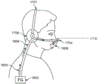
Fig. 17 depicts a user airflow interface including a headset delivering air suitable for use with some embodiments of the present technology.
FIG. 18 illustrates a delivery nozzle suitable for use with some embodiments of the present technology.
Fig. 19 depicts a user airflow interface including a headset for delivering and removing air suitable for use with some versions of the present technology.
Fig. 20 is an example of a self-adjusting/repositionable gooseneck suitable for use with some embodiments of the present technology for delivering air.
Fig. 21 is an example of a zone of directable delivery of air suitable for use with some versions of the present technology.
FIG. 22 depicts an invisible cloth interface suitable for use with some versions of the present technology.
Fig. 23 is a side view of a stealth cloth port suitable for use in some embodiments of the present technology.
Fig. 24 illustrates a stealth drape interface placed within a scarf suitable for some versions of the present technology.
FIG. 25 depicts a user airflow interface including a cap for delivering air suitable for use with some embodiments of the present technology.
Fig. 26 illustrates a user airflow interface including a harness for delivering air suitable for use with some embodiments of the present technology.
FIG. 27 illustrates a user airflow interface including a glove suitable for use with some embodiments of the present technology.
Fig. 28 illustrates a user airflow interface including a collar, shirt, goggles, face mask, suitable for use with some versions of the present technology.
FIG. 29 illustrates a dual nozzle dispensing design suitable for use with the present technology.
FIG. 30 illustrates an anemometer suitable for use with embodiments of the present technology for adjusting airflow position and intensity.
FIG. 31 is a diagram illustrating gas source dispersion, in accordance with embodiments of the present technique.
FIG. 32 depicts a sagittal view of a user and a user airflow interface suitable for use with embodiments of the present technology.
Fig. 33 and 34 depict a supply quality score simulation for embodiments of the present technology.
FIG. 35 illustrates an exemplary controller in some versions of the present technology.
Fig. 36A and 36B illustrate passive clean air systems suitable for use with embodiments of the present technology.
Fig. 37A and 37B illustrate a compact blower suitable for use with embodiments of the present technology.
FIG. 38 illustrates a passive filter suitable for use with embodiments of the present technology.
FIG. 39 is a block diagram illustrating a clean air server system suitable for use with embodiments of the present technology.
FIG. 40 illustrates a user airflow interface including a water bag suitable for use with some versions of the present technology.
FIG. 41 illustrates a user airflow interface including a nose clip suitable for use with some versions of the present technology.
FIG. 42 illustrates a user airflow interface including a mouthpiece suitable for use with some versions of the present technology.
FIG. 43 illustrates a user airflow interface including a motion strip suitable for use with some versions of the present technology.
Fig. 44 illustrates a user airflow interface including a sliding face mask suitable for use with some versions of the present technology.
FIG. 45 is an exemplary fan curve table including one or more stages of blowers connected in series as suitable for some versions of the present technology.
FIG. 46 is an exemplary fan curve including one or more stages of various blowers connected in series and/or in parallel as may be suitable for use with some versions of the present technology.
Detailed Description
Before the present technology is described in detail, it is to be understood that the technology is not limited to the particular embodiments described herein, as such embodiments may vary. It is also to be understood that the terminology used in the disclosure is for the purpose of describing the particular embodiments discussed herein, and is not intended to be limiting.
4.1 overview
In one form, the present techniques are directed to providing air, such as clean air, to a user. Some devices may be used to provide a flow of clean air, depending on the needs of the user. For example, the Clean Air System (CAS)101 of fig. 1 may include a filter 103 and a gas flow generator 1603 for supplying pressurized breathing gas to a user via an air delivery conduit 1604, such as a delivery tube, the air delivery conduit 1604 leading to a user interface 104 that may output air to the user.
In some cases, the techniques may be implemented to provide a more immersive "four-dimensional (4D)" entertainment experience. Such a system may provide a sensory experience beyond visual and auditory. For example, the system may provide an entertainment experience through olfactory, tactile, or gustatory stimuli. In addition, the system may provide changes in humidity and temperature to the user. The exemplary entertainment system 102 of FIG. 1 may include an airflow generator 1603 coupled to a filter 103, such as those implemented for a CAS 101. However, the user airflow interface 104 and the airflow generator 1603 may also be connected with the sensory monitoring and stimulation unit 105. The sensory monitoring and stimulation unit 105 may be implemented to adapt the air provided to the user airflow interface 104 to manipulate the user's experience, such as in connection with an entertainment modality (e.g., movies, games, advertisements, etc.).
In some examples, the system of the present technology may employ a filter 103 to filter particles from the airflow prior to providing the airflow to the user. The filter 103 can remove volatile gases as well as odors, bacteria, viruses from the ambient air. The air passing through the filter may be provided to a user. The filter may be in the form of a cartridge that can be easily placed into and removed from the system. Different filters may provide different types of filtering depending on the needs of the user. For example, some filters may provide odor elimination, while other cartridges provide bacteria removal. In some examples, multiple filters 103 may be used. For example, a pre-filter may be placed on the inlet of the gas flow generator 1603 and a primary filter may be placed on the outlet of the gas flow generator 1603.
In some embodiments, the user airflow interface 104 is used to deliver air to a user by creating an air curtain. The air curtain can separate the ambient environment into two separate environments: an internal environment and an external environment. The interior environment may allow clean air or air with controlled sensory characteristics (such as particles, fragrance, humidity, temperature, etc.) to be delivered into the airways of the user. Alternatively, the user airflow interface 104 of the CAS101 may be hidden in clothing (such as a scarf or a high collar sweater). Alternatively, its appearance looks like a fashion accessory rather than a medical device. The user airflow interface 104 may be applied to avoid or eliminate contact with the face or head. Therefore, the user's face does not typically form a mark. Thus, the user airflow interface 104 can minimize interference with the user's line of sight (i.e., it may not be in the user's line of sight) and is not noticeable by third parties.
Sensors may be located at or near user airflow interface 104 or airflow generator 1603 to sense ambient environments, such as ambient wind conditions and pollution levels. In addition, the sensor can measure health indicators such as heart rate and body temperature. The information read by the sensor can be recorded in time and recalled later. These sensors may be placed in the same or different housings as gas flow generator 1603. Just like the user airflow interface 104 of CAS101, the sensors may be hidden in clothing (such as a scarf or a high collar sweater). Alternatively, the appearance of the sensor looks like a fashion accessory rather than a medical device. The sensor should not make unnecessary contact with the face or head. Thus, the sensor should not restrict the line of sight of the user.
Information may be received from sensors or online resources. Such information may be used to provide feedback to the user, such as through a smart phone, online profile, or other internet connected device. In one example, the system may query weather forecasts or local air quality indicators to assess the filtering strength required for the day. In addition, information received by the sensors may be used to cause the system to automatically adjust or provide alerts to the user to adjust certain parameters. For example, an anemometer and accelerometer may be utilized to enable user air flow interface 104 and/or air flow generator 1603 to change its operation in real time by adjusting the directional angle or wind speed of the air curtain. The user can also be informed by the information recorded by the sensor when the filter should be replaced. For example, a filter for removing odors may be in the system, but a filter for removing pollen may also be recommended because pollen readings are high. Thus, the system may notify the user to change filters.
In some embodiments of the technology, a sensory monitoring and stimulation unit 105 may be used. The sensory monitoring and stimulation unit 105 may include a scent cartridge or other sensory cartridge for providing airborne physical effects to the user airflow interface 104. These fragrance and sensory cartridges can be easily replaced. In addition, the cartridge may include a plurality of stimulants including projectable substances having different fragrances, textures, and temperatures. These projectable materials may have any viscosity, air/moisture ratio, moisture content, or particle size.
In some examples, airflow generator 1603 may be wirelessly connected to upload/download data related to usage, weather, environmental conditions. In addition, data from airflow generator 1603 may be recorded to quantify self-functionality. The amount of clean air inhaled by the user may be recorded and the expected remaining life of the filter cartridge/fragrance cartridge/sensory particle cartridge used may be recorded.
In some examples of the present technology, the 4D entertainment system may be connected with any gaming console, such as a sony's gaming station, microsoft's Xbox, or other media playing device such as a blu-ray player and smart tv. Wireless or wired connections may be made to these devices. The 4D entertainment system may upload and/or download data to these devices.
4.2 gas flow Generator
4.2.1 introduction
Both Clean Air Systems (CAS) and 4D entertainment systems may establish an air curtain to provide air to a user. Air curtain systems typically require significantly higher airflow rates than are provided with Positive Airway Pressure (PAP) therapy provided by typical mask interfaces. A positive air pressure relative to the ambient air pressure may be maintained in the enclosure maintained by the air curtain to prevent air from contacting the housing exterior. Typically such positive pressure on the user's face is lower than that obtained by PAP therapy, as low positive pressure may be sufficient for the face, whereas for PAP therapy the pressure must be high enough to open the user's airway and maintain it in an open state.
The air flow provided by the system that establishes the "air curtain" can provide air at a high flow rate. Additionally, the pressure required across the blower (e.g., the pressure gain from the blower inlet to the blower outlet) can be large. For example, because the blower still needs to overcome the pressure loss in the system. For example, as the air flow passes through the one or more filters 103, the air delivery conduit 1604, the user air flow interface 104, and the intermediate connectors, the air pressure may drop substantially between the blower outlet and the user's face. The pressure differential between the blower outlet and the user's face may be further varied according to a number of other parameters including, but not limited to, the geometry of the pneumatic path (e.g., cross-sectional shape and area of the path, length), the type of filter used, and the size of the filter used.
In this case, airflow generator 1603 needs to produce a high flow rate while the user's face builds up positive air pressure. Thus, some motors and blowers may be more suitable for this task than others.
4.2.2 Motor-blower
The blower may be configured to have multiple stages in series. That is, a blower having one stage is used to receive an airflow exiting from the other stage of the blower. So configured, the airflow pressure can be increased, but the same flow rate can be maintained. Examples of such blowers include the blowers disclosed in PCT patent applications WO2013020167and WO199806449, which disclose blowers having two, three, four or more stages.
A blower configured with multiple stages in series is more suitable for PAP applications with the objective of providing sufficient pressure to open the airway of the user, such as by providing up to 30cm H at the patient interface2The pressure of O. The blower typically includes an electric motorTo provide rotational motion and the maximum rotational speed of the motor is often predetermined as part of the motor design. Therefore, to achieve the desired air pressure, additional blower stages may be introduced in series to increase the air pressure at the same rotational speed. FIG. 45 is a schematic fan curve for a blower rotating at 46.8k RPM, including one or more stages connected in series to increase the pressure of the airflow exiting the blower at a predetermined rotational (e.g., motor) speed. As shown in fig. 45, although the rotational speed of the blower is not increased, an additional series stage is introduced to increase the air pressure.
For applications requiring higher flow rates, a series blower arrangement is not suitable. For example, the air curtain setting may be implemented with a typical or maximum predicted flow rate that exceeds the PAP device, and which has a lower pressure characteristic, as described below. In addition, air filtration systems including masks and vents (e.g., continuous vents or flexibly configured vents) may require higher flow rates because awake users use higher lung volumes than PAP users while sleeping. If a user is performing physical activities such as walking, cycling, golfing, etc. with moderate intensity, the user's lung capacity will be higher. Also, a worker may need a higher lung capacity, and the worker may work in a potentially contaminated environment such as a construction site. The pressure provided in the air curtain arrangement may be much lower than the pressure provided to a patient undergoing PAP therapy. The pressure outside the airflow setting need only provide a filtered air environment at a positive relative pressure to prevent air from entering, rather than requiring the airway PAP device to be opened by pneumatic pressure.
FIG. 46 is an exemplary fan curve for various blower embodiments, such as implementing multiple parallel blowers to increase the flow rate of air exiting the blower at a predetermined rotational (e.g., motor) speed.
FIG. 46 shows that for a predetermined flow rate (such as 50L/min as shown), the introduction of additional blower stages in series can significantly increase the blower outlet pressure, which is, in contrast, at a much higher pressure when additional blower stages in parallel are introducedThe extent remains unchanged. The introduction of additional parallel blower stages can be at a predetermined pressure (e.g., 15cm H as shown in the figure)2O) significantly increases the blower outlet flow rate, whereas the additional series of blower stages have little effect on the blower outlet flow rate. Thus, the parallel arrangement of blowers is more advantageous for the air curtain arrangement as a higher air flow is provided without increasing the pressure.
One example of a blower suitable for use in air filtration applications may be a blower having multiple stages in parallel and driven by a single shaft as shown in FIG. 2. Such a blower may include a first inlet 201 at a first end, a second inlet 202 at a second end, and a shaft 205. The shaft 205 may be fixedly coupled with the first impeller 203 and the second impeller 204. The first impeller 203 and the second impeller 204 may be driven by a shaft 205. The blower may also include first and second outlets (not shown) to deliver the airflow received through the first inlet 201 and the second inlet 202, respectively, at an elevated pressure. In high flow, low pressure applications, a swirl outlet may be used. The scroll-type outlet may increase efficiency and thereby reduce power consumption based on battery usage. In addition, the scroll outlet may allow for smaller sizes when packaged.
Fig. 3 shows an isometric schematic of a blower 300 having two parallel stages. The blower may have two stages 301 and 302 and a motor 307. Air may be drawn in through both inlets 303 and 304 and expelled through both outlets 305 and 306. In some embodiments, the air streams exiting the blower may be combined into one stream, or kept separate, e.g., directed to different areas of the user. In some forms, the air curtain device may include a plurality of outlets, such as one outlet providing the air curtain and one outlet providing a fresh air flow to the user for breathing. In this form, the airflow from the first outlet may provide the air curtain flow and the airflow from the second outlet may provide the fresh airflow to the user.
In another example, the blower may include a mixing chamber downstream of the respective outlets as shown in fig. 3B. The mixing chamber 310 may house the blower 300 therein and receive multiple airflows from the blower stages 301 and 302 and combine the airflows into one airflow. Air provided to blower stages 301 and 302 may be received through an inlet 311 in the mixing chamber. The one gas stream may be output through the outlet 312. In some forms, the amount of noise generated may be reduced by configuring the mixing chamber, such as to act as a silencer. The mixing chamber may thus comprise one or more of an acoustic foam, a helmholtz chamber, a baffle, etc. The mixing chamber may be used to reduce stray noise and/or the noise of the blower output.
Another suitable example of a motor suitable for providing the air curtain may be a single stage blower as shown in fig. 4. The single stage blower may include a motor 405, single impeller blades 402 having a small height and radius aspect ratio, a shaft 403, an inlet 401, an outlet 404. In some embodiments, the impeller may have a height greater than a portion of the impeller radius to drive a large volumetric flow rate of air through the blower at a predetermined rotational speed.
As described above, a motor with a stage blower may be used. Fig. 5A and 5B illustrate a motor having a multi-stage blower. FIG. 5A shows a dual stage blower and FIG. 5B shows a three stage motor. Such a blower may be a centrifugal blower having an inlet 501, an outlet 504, a shaft 502, and a motor 503. PCT patent application WO2013020167 describes an example of a similar blower in more detail. Such blowers comprise a series of blower stages and are therefore suitable for applications where the pressure required at the outlet is higher than would be the case if the arrangement included a similarly configured series of blower stages.
An axial blower such as that shown in fig. 6 may be suitable for use in this application. Axial blowers can typically produce high flow rates and lower pressures compared to centrifugal fans. As shown in fig. 6, the axial blower includes a rotor 603 coupled to a motor shaft 602, a blower housing 601 surrounding the rotor and including stator blades. The blower may include multiple stages 604, where each stage may be located on one or more separation assemblies, or multiple stator or rotor stages may be located axially separated on a single element as shown below.
Fig. 7A is a rotor compatible with the axial blower shown in fig. 6. The multi-stage rotor may be formed on a single molded body 703, the single molded body 703 including an axial groove 703 to which the motor is coupled. A plurality of rotor stages are integrally formed on a unitary body of the rotor. The integrally formed unitary rotor may reduce manufacturing costs, reduce the number of components, and reduce manufacturing tolerances. Each stage 702 is shown as being axially aligned with each other and having the same geometry. Fig. 7B and 7C illustrate an axial stator stage that may be formed by the rotor of fig. 7A. The rotor stage 704 may be aligned with the blower housing 705 to form an axial stator stage. In some forms, the stages need not be axially aligned, and each individual stage may be arranged differently than the other stages.
Another example of a suitable blower may be a blower that includes a centrifugal stage and an axial stage as shown in fig. 8A and 8B. As shown in FIGS. 8A and 8B
As shown in fig. 8B, the blower may include a centrifugal stage 801 as a first stage. Air from the centrifugal stages may follow an annular path formed in the blower downstream through axial stages 802 and 803. Such a configuration may increase the pressure and flow rate of the gas stream to accommodate certain examples of the present technique.
Fig. 9A to 9C show a rotor comprising a top with a centrifugal stage, which is arranged towards the inlet. The rotor may include impeller blades 903 and an impeller shroud. Further, the rotor may comprise an axially extending wall 901, the axial vanes 902 being formed on the extending wall 901. The axially extending wall may also form part of the annular gas flow path through which gas flows. This form of rotor may also include a circular cavity 904 through which the rotor is coupled to the motor.
Fig. 10A and 10B show a first half of a housing 1001 having an inner wall. Stator vanes 1002 may be formed on the inner wall. The housing 1001 is configured such that the stator vanes 1002 for both the centrifugal and axial stages of the blower are formed on a straight wall. This structure can improve the manufacturability of the housing. Each half of housing 1001 includes a key and complementary grooves configured to engage each other. Constructing the multi-part housing 1001 allows each part to be molded with the stator vanes 1002 being integrally formed and projecting inwardly from the inner wall.
The motor may be placed in a motor housing. Fig. 11A and 11B illustrate an exemplary motor housing. The motor housing may include a cavity 1101 and the shaft may extend out of the cavity 1101. In addition, the motor housing may include a set of outlet cavities 1104 for airflow. The motor housing may also include connection points 1102 and 1103 to connect the motor housing to the motor.
Another example of a motor that may be used in an air curtain system may be a tesla blower. The tesla blower may have a thin flat disk, giving the blower a slim profile. Accordingly, the blower can be easily hidden and unobtrusive. Because the tesla blower has no blades, it may not produce a noise output when operating.
4.2.2.1 Motor-blower of this technology
The one or more blowers described above are applicable to examples of the present technology such as air curtain devices, air filtration devices with patient interfaces, or recreational air systems.
The blower may be designed and selected as appropriate depending on the intended use and shape or size of the system. The size of the blower may be increased or decreased to vary the output flow and/or pressure. Then, by proper blower structural design, the blower of the present technology can be obtained with the most concealed appearance to its user and maximizing its operating time by minimizing power consumption. For example, a blower with too many stages in series is too bulky for practical use.
If the blower is located near the point of delivery of the airflow to the user, such as on the user's shoulder, and the air delivery conduit has a larger diameter, such as 19mm, then a blower capable of providing the desired flow rate at low pressure is sufficient. Such blowers may be single stage centrifugal blowers or multi-stage axial blowers. However, if a higher flow rate is desired, the centrifugal blower may include multiple blower stages in parallel.
In one example, the blower is located away from the point of delivery of the airflow to the user, such as at the user's hip. If the blower is connected to the user airflow interface through a narrow tube, the blower needs to be able to provide high pressure. Accordingly, hybrid axial and centrifugal blowers may be suitable.
4.2.3 air curtain
An air curtain can be generated to separate the ambient environment into two separate environments: an internal environment and an external environment. The interior environment generally includes air exiting the air curtain system (e.g., user air flow interface), while the exterior environment includes air that has not yet passed through the air curtain system. A positive or equivalent air pressure relative to the ambient air pressure may be maintained in the internal environment maintained by the air curtain to prevent the ingress of air outside the air curtain "enclosure".
Fig. 12 shows a schematic of an "air curtain" system. In this schematic, the blower 1202 is located near the air tube 1201. The blower 1202 is located near the air tube 1201 to minimize pressure drop and maximize extended battery life. For example, as the air flow passes through the filter 1204, the conduit and the air tube 1201, the air pressure between the outlet of the blower and the user's face may drop significantly. The pressure differential between the blower outlet and the user's face may be further varied according to a number of other parameters including, but not limited to, the geometry of the pneumatic path (e.g., the cross-sectional shape area and length of the path), the type of filter used, the size of the filter used. The blower 1202 and the filter 1204 may be part of an airflow generator.
In the system of fig. 12, for example, the air tube 1201 is 25cm in length and 19mm in diameter, and the blower 1202 is suspended within a sound shield 1203 and provided with a large inlet filter 1204. The system of FIG. 12 can have a constant flow, such as 150L/min, and a pressure across the blower, such as 12cm H2And O. The estimated energy consumption is 13W. The filter 1204, conduit, air tube 1201 may cause pressure loss. In an exemplary air curtain system, the air conduit 1201 may have, for example, 0.25cm H2Pressure loss of O, filter 1204 may have 4cmH2Pressure loss of 0. Further, each air delivery conduit may be subjected to 0.1cm H2Pressure loss of O. Thus, assuming a static power of 1W, 6 cells (12Wh cell capacity) can be out of box for 4.8 hours. It should be noted that the numbers provided are exemplary and that other numbers and ranges with the same technology are possible.
An appropriate flow angle can improve the efficiency of providing air from the air curtain system. The air flow rate has less effect than the flow angle in increasing the proportion of air drawn by a user of the air curtain system. Turning to fig. 31, the Y-axis presents simulation results for a user inhaling an air curtain system providing a percentage of air ranging from 0% to 90%. In this simulation, readings were taken at a variety of angles, distances, and flow rates. As shown in fig. 31, two flow rates of 150 liters/minute (2.5 meters per second) and 300 liters/minute (5 meters per second) were used, labeled qin. Each of the two flow rates is applied at three different distances, in millimeters, between the user's airflow interface (such as an air tube) and the user's nares. These distances are labeled as front offsets in fig. 31. The range of flow angles from the outlet of the user's airflow interface to the nares is measured in degrees for each distance and labeled as the flow angle (α) on the X-axis. All measurements of the simulation were taken at an ambient air temperature of 25 degrees celsius with no ambient air velocity. Fig. 32 shows a sagittal view of how the anterior offset distance (anterior offset) and flow angle (a) are measured.
As shown in the scatter plot of fig. 31, the priority for the importance of the percentage of clean air inhaled by the user is the angle (flow angle), distance (front offset), and then flow rate (Q in). Because the airflow is directed to the user's airway with a flow angle of about 40 degrees, the percentage of clean air inhaled by the user is, in most cases, higher than 60%.
Figure 33 shows the air source from an air curtain system with a 50mm front offset. The flow angle was 17 degrees and the flow velocity was 2.5 m/s. As shown in fig. 33, the air source from the air curtain system located over the user's nares is approximately 50%. Fig. 34 shows an air curtain system with a front offset of 75 mm. The flow angle was 30 degrees and the flow velocity was 2.5 m/s. As shown in fig. 34, the air source from the air curtain system located over the user's nares is approximately 75%. The higher flow angles provided in fig. 4 provide a user with a higher percentage of clean air from the air curtain system.
4.3 Intelligent air cleaning technology
The air curtain system can be used to create a Clean Air System (CAS). The CAS may include a plurality of filters to remove particles and gases from the air and then provide the filtered air to the user. CAS can also remove volatile gases as well as odors, bacteria, viruses from the ambient air. After filtering the air, the CAS may then provide the filtered air to the user through the user airflow interface 104. The air may be provided in the form of at least one air curtain. In some examples, the CAS may send all the material on the display. The CAS may have a control function directly on the housing. In other examples, the CAS may send all the data to the smartphone or computer program and may also present the data through an online database. The CAS may also be controlled by a Graphical User Interface (GUI) displayed on a smartphone, tablet, computer, etc.
As shown in fig. 1, the active clean air system may include an airflow generator 1603, a smart clean air filter 103, and a user airflow interface 104. The airflow generator may be any motor as described above and may include a filter and a sensor. FIG. 14 illustrates an exemplary embodiment of a CAS. Dirty air 1401 is first blown through pre-filter 1402 to the airflow generator. The pre-filter 1402 removes particles from the ambient air that may damage the motor 1403. The motor 1403 shown in fig. 14 may then blow air through the primary filter 1404. The primary filter 1404 may remove harmful particles and/or volatiles from the air. The filtered air may then be output to a user through user airflow interface 104 as clean air 1405.
As shown in fig. 35, the CAS may also include a controller 3501 for controlling the operation of the airflow generator 1603. For example, the controller 3501 may be used to adjust the flow rate of the airflow generator as well as to adjust the air pressure generated by the airflow generator. The controller 3501 may be housed in the same housing as the CAS. The user airflow interface 3504 may be directly coupled to the controller 3501 of the CAS housing. The dirty air 3503 may then be filtered by the controller 3501 of the CAS housing, followed by delivery of clean air to the user airflow interface 3504. The controller 3501 may include a touch screen to allow a user to adjust settings of the CAS, such as flow rate, airflow pressure, airflow temperature, and airflow humidity. Alternatively, controller 3501 may be operated by controller device 3502, and controller device 3502 may be a smartphone, tablet, computer, standalone device, or the like. Controller device 3502 may be in wireless communication with controller 3501 to allow a user to remotely control controller 3501.
In some embodiments, the CAS may be configured to operate passively, without a blower or controller. For example, as shown in fig. 36A, the CAS can include a delivery system that includes a cartridge holder 3690, a gas delivery conduit 3670, and a gas flow interface 3680. As shown in fig. 36B, the cassette holder can receive cassette 3620. The case 3620 may be constructed of one or more materials including metal or plastic, which is lightweight and can withstand high internal pressures. The case 3620 may contain clean, compressed air that may be delivered to the user interface 3680 via a gas line 3670.
A regulator valve on the delivery system (not shown) may control the flow rate of compressed air through air delivery conduit 3670 to user interface 3680. Such a delivery system is compact, lightweight, and quiet during operation because no blower or controller is required. In some embodiments, a passive cassette delivery system can be used to supplement an active CAS by providing increased airflow when desired by a user. In addition, the passive CAS can also be used as a backup for the active CAS. In this regard, the regulating valve may be opened automatically or manually in the event that the active CAS is not functioning.
The cartridge 3620 can be filled with compressed clean air by the recharging purifier base 3610. In this regard, the recharging purifier base 3610 can filter, compress, and optionally humidify and/or fragrance air. The cartridge 3620 can be placed in a charging port 3630 within the charging purifier base 3610. The charging port 3630 may open a valve 3625, such as a spring valve, on the case 3620. The recharging purifier base 3610 can then inject filtered, compressed, and optionally humidified air into the cartridge 3620 by opening the valve 3625. After the cartridge 3620 is removed from the charging port 3630, the valve 3625 may be sealed. The cassette 3620 can store enough compressed air for one hour of operation, or longer or more, until recharging is needed.
The recharging purifier base 3610 can compress air by using an impeller blower. In this regard, the impeller blower may draw air in through the port 3640, and the port 3640 may include an initial filter to filter large particles in the air before the air passes through the impeller blower. The impeller blower may then blow air into the charging box 3620, compressing the air as more air is blown into the charging box. In some embodiments, straps 3650 and clips 3660 can be attached to the recharging purifier base to allow the base to be secured to a user or other object for carrying. In this regard, the recharging purifier base may be powered by a battery or a wired power source.
In some embodiments, the impeller blower may blow air over one or more heating elements that may vaporize a liquid, such as water, thereby increasing the humidity of the air. In other embodiments, humidity can also be introduced into the system through a separate water cartridge within the recharging purifier base 3610.
In some embodiments, the delivery system may include an antimicrobial material liner and/or an antimicrobial pack to reduce any bacteria and/or odors that may form within the device. Such antimicrobial materials may include silver thread, merino wool or bamboo charcoal to adsorb bacteria and odors. Such liners and/or bags of material may be removable, replaceable, and/or flushable. The air curtain system can be designed to be portable and compact so as to be portable or wearable. For example, a compact blower, as shown in fig. 37A, can include an impeller 3720 for generating a flow of air, a conduit 3730 for delivering air to the patient interface, and an attachment space 3740 in which controllers, batteries, and/or sensors can be placed. In addition, the compact blower 3710 may also include an intake filter 3770 to remove airborne particles drawn in by the impeller 3720. The compact blower may be attached to a user or other object by strap 3760.
Returning to fig. 37B, the compact blower 3710 can be configured such that it can be attached to the user's body 3790 with a strap 3760. In some embodiments, the compact blower 3710 can be less than 10mm wide, or more or less, allowing it to be placed in the pocket 3795. To allow air to be drawn into the compact blower placed in the pocket 3795, an extender may be attached. Referring to the enlarged view of the pocket 3795 in fig. 37B housing the compact blower 3710, a filter extender 3775 can be attached to the intake filter 3770. Thus, the intake filter 3770 can draw air into the compact blower through the extender 3775 located outside the pocket or just inside the pocket. In some embodiments, a compact blower may be placed near the user's head to reduce the flow impedance caused by the conduit 3730, as well as to reduce drag as the user moves their head.
Since the air curtain system may be portable, it may be battery powered. Furthermore, it should be possible to hide or disguise the unit from view, so that the user appears not to be using the medical device. In some embodiments, the air curtain system may provide an air curtain when the user inhales to minimize power usage.
The filter for clean air may be cylindrical and may be easily placed into and removed from the CAS. Different filters may provide different types of filtering depending on the needs of the user. For example, some filters may provide odor elimination, while other cartridges provide bacteria removal. In some embodiments, multiple filters 103 may be used to increase the effectiveness and/or efficiency of the filtering. Since each filter provides filtration of a different type of contaminant, multiple types of filters may be used simultaneously. In some embodiments, the CAS may be self-configuring to automatically control the flow of air through a particular filter based on particulates and/or volatiles in the user's environment. They can be easily replaced when filters are not needed or they do not work properly. In some embodiments, an unrestricted filter may be used that provides no or very little airflow impedance.
One exemplary filter type is a high efficiency particulate air filter (HEPA filter). To meet the HEPA standard of the U.S. government standard, the air filter must remove 99.9% of the 0.3 μm particles from the air passing through the HEPA filter. HEPA filters function by intercepting particles in the air as it passes through the filter. As the air passes through the HEPA filter, particles in the air are blocked on the fibers and are removed from the air.
Another example of a filter that can be used in CAS is a polarized media electret filter. Most polarized media electronic air purifiers convert 24 volt current into a safe dc voltage to establish a polarized electric field. When particles in air pass through an electric field, they become polarized. The polarized particles are then adhered to a disposable fibrous media pad.
Ionization purifiers are another type of filter that can be used with CAS. Ionization purifiers use electrically charged surfaces or needles to generate charged gases or gas ions. These ions then attach to particles in the air as it passes through the ionization purifier. As the particles continue through the ionizer purifier, they are electrostatically attracted to the charged collector plates.
A heat sterilizing filter may also be used. This technique can heat air to about 200 ℃ (392 ° F). As the air is heated, particles of bacteria, viruses, dust mite allergens, mold and fungal spores are incinerated. The use of a heat sterilising filter can remove potentially up to 99.9% of the microbial particles.
Activated carbon filters can also be used for CAS. Activated carbon is a porous material that can molecularly adsorb volatile chemicals. Carbon filters are commonly used for compressed air and gas purification to remove fuel vapors, odors, and other volatile organic compounds from the air.
Electrostatic filters can also be used in CAS. Electrostatic filters can function by sandwiching layers of material together. Air may then pass through these layers. As air passes through the material layer, particles in the air may become electrically charged due to friction between the particles and the filter layer. The charged particles may then attach to other layers within the filter having an opposite charge to the charged particles.
Photocatalytic oxidation filter systems can also be used in CAS. The photocatalytic oxidation filter system is capable of thoroughly oxidizing and degrading organic contaminants. For example, low concentrations of volatile organic compounds (such as hundreds of parts per million or less) are most likely to be completely oxidized. Photocatalytic oxidation filter systems use short wave ultraviolet light to excite a catalyst, typically titanium dioxide (TiO2), and oxidize bacteria and viruses.
Table 3 below provides an overview of the filter types and the types of contaminants that can be effectively removed.
TABLE 3

The Clean Air System (CAS) may also contain sensors and wireless communications to monitor the system, ambient environment, and users. The wireless communication may be in the form of GPS, Bluetooth, Wi-Fi, cellular data network, or the like. Utilizing sensors and information obtained through wireless communication may allow the CAS to provide reactive protection based on the received data. The CAS can also monitor the health and environment of the user.
A Clean Air System (CAS) may provide reactive protection. For example, the CAS may continuously monitor in real time those contaminants listed in table 3. If the CAS determines that a contaminant is present, the system can notify the user. The CAS can also use the information received from the sensors to provide alerts to the user. Such an alarm may be issued by an intelligent pollution alarm system implemented on the CAS. The smart pollution alarm system may use the readings of the pollution sensors, such as the PM 2.5 sensor, to project or display current or historical readings of the sensors on the device in a visible or audible manner. Thus, the user and other nearby bystanders can be informed of the level of air pollution in their environment. In another example, the CAS may trigger an alert indicating that the air temperature and contaminant content of the user's current location may trigger a health condition, such as an asthma attack. In addition, the system may alert the user to increase the filtration intensity or to swap filter cartridges in order to more effectively filter the detected contaminants.
Alternatively, the CAS can automatically adjust the filtering based on the sensor readings. The clean air system may include one or more air quality sensors connected to a controller in a feedback loop. The controller may be configured to set operation of the one or more filters in response to signals from the one or more air quality sensors. For example, if the air quality sensor detects a large amount of pollen, the controller may determine what type of filter is effective in removing pollen. Since the HEPA filter can effectively remove pollen, the controller may cause the CAS to begin filtering air through the HEPA filter. Alternatively, the controller may notify the user that the pollen count is high and that the HEPA filter should be used. The CAS may also alert the user that they have been in the contaminated area for too long, they should seek a cleaner, less contaminated area.
The controller may also be configured with a location sensor, such as a GPS sensor, and wireless communications (e.g., a Wi-Fi antenna and memory module) to access online databases and information. For example, the controller may use GPS to detect the location of the user. Based on the location data, the controller may use wireless communication to access a database of known contaminants in the area. After the controller determines the location and contaminants of the area, the controller may set operation of one or more filters of the CAS to remove the contaminants from the supplied air. Alternatively, the controller may not set the operation of the one or more filters, but may notify the user to set the operation of the one or more filters.
The controller may also use wireless communication to access daily and regional weather and air quality forecasts. Based on the received weather and/or air quality data, the controller may set the operation of one or more filters to protect the user from inhaling any harmful particles. Further, the controller may set an intensity level for filtering. Alternatively, the controller may not set the strength or operation of one or more filters, but instead inform the user to set the operation or strength of one or more filters. The received weather and/or air quality data may be updated as the user location changes.
Health and environmental monitoring of the user may also be performed by the clean air system. For example, the controller may be coupled with one or more user sensors configured to detect physiological data of the user. Such data may be heart rate data, perspiration data, temperature data, breathing rate data, O2 saturation data, and the like. The sensor may be any one or more of a heart rate sensor, a humidity sensor, a thermistor, an airflow sensor, an oximeter, etc. Physiological data from the sensor may be recorded and provided to the user. The communication with the user may be on the CAS or may be accessed through an online database on a computer or smartphone. Additionally, the physiological data can be sent to an online database that includes a user profile. Thus, a user can access the database and view the information in their profile. In addition, a feedback signal can be used to switch the CAS on and off if the user has fallen asleep or awakened, respectively. In some embodiments, the CAS is always on. In some embodiments, the physiological data may be analyzed to determine a disease of the user. For example, captured user data while the user is asleep may be analyzed to determine sleep disordered breathing.
The CAS may also include an eye tracking sensor. An eye tracking sensor and corresponding algorithm may be used to monitor what the user is focusing on. The purpose of the eye tracking sensor is to locate the user's eyes, which are facial landmarks in order to determine the direction in which the user's head is used to adjust the nozzle. For example, if the user turns the head to look at something, the nozzle will be adjusted to maintain alignment with the air direction of the user's respiratory tract entrance.
Real-time pollution and location data from a network of similar systems may be collected and sent to a database. This collected information can be used to create a real-time map of the intensity of contamination. The real-time pollution intensity can display the pollution level of a specific position. In addition, the map may be used to alert other users around the hazard point. Maps may also help researchers understand the pollution tendencies of certain areas.
The intelligent pollution navigation program can also be implemented on the CAS. For example, based on the location and pollution data received from the sensors, the CAS can provide navigation data similar to traffic maps and provide guidance to the user and/or traveler to avoid certain areas with high levels of pollution. In one example, the CAS can receive a destination from a user. The CAS can then direct the user to the destination on-screen or voice-navigated, avoiding having the user navigate through a route with areas of high pollution. In some embodiments, the CAS can be connected to the user's smart phone, and the phone's GPS and navigation software can be used in conjunction with the CAS to provide an indication to the user. In one embodiment, the intelligent pollution navigation program can monitor the location of the user and provide them with a notification that they are approaching or within a highly polluted area. In another embodiment, when the location sensor identifies that the user is in an unfamiliar location, such as when traveling, an air pollution safety cue for that location may be provided and the contaminant content and concentration sensed automatically and the filtration adjusted appropriately.
Real-time pollution monitoring can also be converted to an index into an online user profile. This index can tell the user how much contamination they have been in, and how much contamination they have avoided. In addition, the index can provide the user with knowledge of the different types of contaminants they are exposed to. Further, the index may inform the user of the percentage of oxygen inhaled over a period of time. The percentage of oxygen inhaled daily (breathed in breath) per hour per day may be sent to the user on an hourly basis. This information enables the user to see the effectiveness of the protection provided by the CAS.
The CAS may also include one or more sensors configured to detect a direction of the user airflow interface and/or to detect a wind direction and a wind speed. For example, the one or more sensors may include an accelerometer that detects an anemometer of wind and detects a direction of the user airflow interface. Based on information from the anemometer and accelerometer, the computer processor can calculate the optimal air nozzle angle and/or position. In addition, the computer processor may determine an optimal airflow intensity to obtain an optimal proportion of clean air delivered to the user. The computer processor may be connected to a non-transitory memory for storing the recorded data.
Based on the results calculated by the processor, the controller of the device can adjust the operation of the CAS. For example, based on the detected wind and/or direction of the user airflow interface, the processor may determine that it is necessary to change the operation of the airflow generator. Thus, the controller may cause the airflow generator to vary the flow rate. The processor may also determine that an air nozzle within the user airflow interface needs to change position and/or change angle based on the wind and/or direction of the user airflow interface. Thus, the controller may cause the nozzle to adjust to obtain the optimum proportion of clean air delivered to the user.
In some cases, it may be difficult for a user to determine whether the CAS is functioning properly. Thus, the CAS can be configured to provide feedback to the user as to whether the CAS is functioning properly as it should. As shown in fig. 14, the CAS may include a fragrance dispenser in line with the air flow. If the fragrance dispenser is activated, the dispenser may release a scented recognizable scent 1301 into the clean air flow 1302. The scent may indicate to the user 1303 that the CAS is working and providing clean air. In addition, the user can follow the scent to ensure that they breathe in clean air.
In addition to or as an alternative to the active clean air system described herein, passive filters may be incorporated into the system. For example, as shown in fig. 38, a passive filter may be placed over the mouth and/or nose of user 3806. In this way, since the passive filter can supplement or replace the amount of clean air provided to the user, the burden of the blower 3804 of the CAS to provide the user 3806 with the entire clean air can be reduced. In some embodiments, if the demand for clean air filtration is low, the blower 3804 may be turned off to conserve energy, and the user 3806 may rely on the passive filter 3802 to clean the air. Further, the passive filter 3802 may provide a more comfortable experience to the user 3806 because the passive filter may provide sufficient air flow to the user without the blower 3804 applying excess air to the user.
The clean air system may be implemented as an integrated and connected system. In this regard, the CAS may simulate the connectivity of a fitness band or smart watch-type device. Thus, in addition to providing clean air to the user, the CAS can be programmed to function like an extension of a smart phone. For example, the processor of the CAS may be programmed to communicate with the user's smartphone over the communications interface. The communication interface may be configured to receive and transmit signals from the smartphone over a wired and wireless connection. Bluetooth, Wi-Fi, RF, cellular data networks, radio waves, etc. are example forms of wireless communication that can be used between the CAS and the smartphone.
Once a connection is established between the CAS and the smartphone, the user is able to send and receive SMS and MMS messages, as well as send and receive cellular telephone calls. For example, the CAS may include a microphone, a speaker, and/or an earphone, where the user may communicate as if using a telephone. If a video camera is installed in the CAS, the CAS can also be programmed to recognize voice commands and have camera functionality. As an integrated and connected system, the CAS device will be carried and/or worn by the user most of the time, thus increasing the likelihood of use of the device and thus improving the health of the user.
While the user is speaking, the air directed to the nose and mouth of the user may distort the user's voice, dry the user's mouth, or make the user uncomfortable speaking. To avoid such distortion and discomfort, the CAS may include a speech mode. Speech recognition software may be used to implement the speaking mode. The speech recognition software may enable the device to sense when the user is speaking and in response reduce or stop the supply of air to the mouth and nose as the user continues to speak. In some embodiments, the voice software may automatically open the exhaust valve (if present on the CAS) when the system detects that the user is speaking.
The clean air system may also include other integrated intelligent sanitation systems and features. For example, the CAS can include additional tracking functionality to monitor usage and provide feedback to the user based on the CAS usage. Monitoring may be accomplished by using sensors such as contamination sensors, temperature sensors, physiological sensors, and the like. The sensors may monitor the presence and concentration of contaminants, such as those found in table 3, at one or more locations. The CAS can also track where and when the CAS is running. The monitored and tracked data may be stored in memory within the CAS system or uploaded to a cloud-based storage system or a local storage system.
The CAS can use the monitored information to provide feedback to the user. For example, based on the collected data, the CAS can determine when and where the device is most advantageous, the number of hours the CAS is used, the amount of contaminants removed from the user's breathing path (in grams), the filtration efficiency (i.e., how much particles and gas are removed from the user's breath), and the like. The monitored and tracked data may be presented to the user in the form of graphs and charts containing the tracking measurements on the display of the CAS or on the display of another device, such as a personal computer or smart phone. The monitored and tracked data may also be converted to an index within the online user profile. The index may be accessed by a user on the device or by another computing device, such as a smartphone or personal computer connected to the online profile.
The CAS may also include a sports mode. The movement mode may be activated manually by the user or automatically by the CAS. To automatically activate the sport mode, the CAS can use data acquired from the set of sensors, such as humidity data, air temperature data, airflow data, and CO2Concentration data. Once the received data shows signs of motion, such as increased relative humidity due to exhalation, increased minute ventilation, increased exhaled breath temperature, etc., the device may automatically switch to the motion mode. Once in the sport mode, depending on its configuration, the CAS may activate the active exhaust valve. The exhaust valve can blow away air exhaled by the user. CO may also be caused by exercise2The increase in volume accumulates within the interface that partially covers the mouth and/or nose of the user. Thus, alternatively, in addition to the activated vent valve, a carbon filter in motion mode may be introduced to reduce CO2And (4) concentration. Further, in the sport mode, the blower that can turn on the CAS may or increase its output.
In some embodiments, a cooling system may also be added to the CAS to cool the intake air. The cooling system may be an additional valve with a blower and filter to draw cooler air from the environment. Or in addition to drawing cooler air from the environment, the CAS may include a peltier chip that cools the air as it passes through the chip. The cooling system may be automatically activated when the CAS is switched to the sports mode, or may be manually activated by the user.
To help the user achieve exercise goals and encourage use of the device, the CAS may provide breathing and/or use goals. In this regard, the CAS may provide daily, monthly, yearly, etc. goals for the user of the device to incentivize the user. For example, the CAS can provide a daily target for two hours or more or less of use of the device. In another example, the device may direct the user to breathe at the target breathing rate for fifteen minutes, or longer or shorter. The breathing and usage goals provide features that can be used to monitor the progress of the user's respiratory health (e.g., improve the resting breathing rate). The workout goals and the progress toward achieving these goals may be included in an index in an online user profile. The index may be accessed by a user on the device or by another computing device, such as a smartphone or personal computer connected to an online profile. Exercise goals may be updated directly on the CAS or by accessing the user's online profile.
By including an Integrated Inspiratory Muscle Training Valve (IIMTV), the CAS can also promote correct or improved breathing. In this regard, the CAS may activate the IIMTV when respiratory training is requested. The IIMTV may require the user to reach a certain amount of inspiratory pressure before opening and allow the user to inhale air. In this embodiment, the CAS may be a sealed interface. Alternatively, the CAS may be an open interface and by adding other gas molecules such as nitrogen or carbon dioxide, the oxygen level may be reduced to about 15%, thus drawing in fewer air molecules per unit volume.
The CAS may further include one or more sensors configured to detect an inadvertent leak in the system. For example, when delivering air to a user using a hood, such as a mask, a seal should be maintained between the user and the mask to maintain full effectiveness of the device. When a sensor, such as an airflow sensor, detects a leak between the mask and the user, the device may notify the user that the mask should be fastened or replaced. Alternatively, the CAS may automatically trigger the fastening of the hood by an actuator in or mounted to the hood when a leak is detected trying to seal any leak.
When a mask or other such airflow interface is first worn, it may be difficult to obtain sufficient clean air into the mask due to impedance present in the system. Thus, the controller may use an intelligent clean air ramp algorithm. In this regard, the controller may be programmed to provide a maximum flow of clean air to the airflow interface and then slowly decrease the flow of clean air once the user is comfortable with the level of clean air. This configuration has the advantage of saving energy because the blower does not run at full speed for a long period of time.
To further improve user comfort, an Expiratory Activity Valve (EAV) may be used to reduce the build-up of CO at the mask or other airflow interface2Amount of the compound (A). In this regard, the EAV may be triggered to open upon detection of the user's exhalation. Thus, exhaled air will be expelled from the clean air system, immediately exiting CO from the CAS2And reduces the stuffiness feeling of the user. In some embodiments, the CO at the user's mask2Above a predetermined threshold, the CAS may trigger the EAV to open.
The integrated and connected CAS system can also be synchronized with other integrated and connected CAS systems. By synchronizing multiple CAS systems together, a user can monitor the usage of other user devices in the synchronized device group. In this regard, each device may be assigned to a group, such as a group of family members, a group of friends, a group of colleagues, and so forth. Each CAS that is synchronized to a group may monitor the usage history of other synchronized devices within the group. Usage history data that may be monitored may include the number of hours the device was used, respiration and/or usage goals, exercise goals, progress in achieving goals, exercise history, and other such information collected from sensors of the CAS.
In some embodiments, users of each device may be assigned access levels such as an administrator level, a high level, and a base level. An administrator can control all features between the synchronized CAS systems. Thus, the administrator can control which devices can be added or deleted from the synchronized group and the level of access of the users in the group. The administrator may also control what information the user is able to share and/or monitor. For example, an administrator may provide full access to monitor shared information for users assigned a high level, while limiting the data that may be viewed and/or shared by base users. In one example, a group may include five family members, including two parents and three children. Both parents can gain administrator level access, can give older children a high level of access, and can give two smaller children a basic level of access. Thus, parents can monitor and control the usage of all their children. Older siblings with a higher access level can select the information he wants to share and can monitor the devices of his two younger siblings. Two young siblings with a base level of access can only view their own personal information and are blocked from viewing other users in the family group.
In some embodiments, where the CAS includes an earpiece or a hands-free calling device, the microphone and earpiece device may be used as a walkie-talkie device and connected to other clean air systems in the vicinity. Sessions may be enabled between all CAS devices within range, or may be assigned only to certain groups that are synchronized, such as synchronized groups of family members.
In some embodiments, the CAS may perform a baby monitoring function. For example, the CAS can be attached to a crib or placed near an infant. Information collected by sensors on the CAS monitoring the infant may be forwarded to the caregiver or uploaded to a storage location such as a cloud storage location. The caregiver's CAS device may display the forwarded information or may access the forwarded information from the cloud storage using another computing device.
The clean space server may aggregate the information and provide the information to the CAS device. For example, as shown in FIG. 39, a Clean Space Server (CSS)3902 can receive information from a variety of sources. Based on the received information, the CSS may send customized updates and reports to the CAS device as well as automatically adjust the operational parameters of the CAS device.
The CSS may consist of one or more servers. The server may be connected to one or more networks, such as a Local Area Network (LAN) or the internet. The CSS may aggregate and store information from various sources connected through one or more networks. The information received from the various sources may include date, time and news updates 3904, weather updates from weather services 3906, location information from GPS 1908 devices (which may be integrated into the CAS device), sensor measurements 3910 from CAS devices or other sensors, CAS information from peer CAS devices 3912 and 3914 (i.e., the CAS devices of the members synchronized to the group).
From various sources, the CSS 3902 can automatically adjust parameters on a particular CAS device to match weather conditions as shown in block 3916, provide weather updates or calculate pollution predictions and forecasts as shown in block 3918, and provide health progress and feedback as shown in block 3920.
In one embodiment, the CSS 3902 can use information received from date, time, and news updates 3904, weather services 3906, GPS 3908, and sensor measurements to adjust the operation of the CAS device. In this regard, based on GPS signals 3908 and sensor measurements 3910 received from CAS devices, the CSS may analyze weather data received from weather service 3906 for a particular time and date received from date, news, and time update 3904 sources. The CSS 3902 can then determine which parameters on the CAS should be adjusted to provide protection to the user based on the received information. In one example, CSS 3902 can use GPS of the CAS to detect the location of the user. Based on the location data, the CSS may access a database of known pollutants for the region at a particular time through weather service 3906 or news update 3904. After the CSS determines the location, time, and contaminants for the area, the operation of one or more filters of the CAS can be set to remove contaminants from the supply air. Alternatively, the CSS may not set the operation of one or more filters, but rather notify the user to set the operation of one or more filters.
The CSS may also use weather service 3906 to access daily and regional weather and air quality forecasts. Based on the received weather and/or air quality data, the CSS may set the operation of one or more filters to protect the user from inhaling any harmful particles. In addition, the CSS may set the strength level of filtering. Alternatively, the CSS may not set the strength or operation of one or more filters, but rather may notify the user to set the operation or strength of one or more filters. The received weather and/or air quality data may be updated as the user location changes.
4.4 sensory entertainment technology
An air curtain system or other user airflow interface may be implemented in the entertainment system to provide further sensory feedback to the user. Such an entertainment system may include some or all of the functions described in the airflow system, with or without air cleaning functions. However, the entertainment system may also include controls for stimulating smell, touch, and/or taste, such as through a provided/generated airflow.
As shown in FIG. 1, the entertainment system may include an airflow generator 1603, a smart clean air filter 103, and a user airflow interface 104. The airflow generator may be any motor as described above and may include a filter and a sensor. If the entertainment system includes a cleaning function, it may be configured as a clean air system with one or more filters as shown in FIG. 14. Dirty air 1401 is first blown through a pre-filter 1402 to the airflow generator. The pre-filter 1402 removes particles from the air that may damage the motor 1403. The motor 1403 shown in fig. 14 may then blow air through the primary filter 1404. The primary filter 1404 may remove harmful particles from the air. The filtered air may then be output to a user through user airflow interface 104 as clean air 1405. However, as shown in fig. 15, entertainment systems typically include an additional sensory particle dispenser 1502. In some embodiments, one or more filters may be replaced by a scent cartridge that can be triggered in synchronization with the entertainment scene (e.g., ocean waves release salty, ocean smells from the scent cartridge into the air). The entertainment system may also include a controller to control the operation of the airflow generator 1603. The controller may adjust the flow rate of the gas flow generator and the gas pressure generated by the gas flow generator.
The entertainment system is capable of connecting to or communicating with various multimedia systems (e.g., televisions, DVD players, game/entertainment consoles, etc.) via a communication interface. The communication interface is configured to receive entertainment signals from the multimedia system over a wired and wireless connection. Bluetooth, Wi-Fi, RF, cellular data networks, radio waves, etc. are example forms of wireless communication that can be used between an entertainment system and a multimedia system.
The multimedia system may be programmed to provide signals to the air flow entertainment system. Entertainment media provided by a multimedia system (such as a movie, television program, or video game) that a user is using may have 4D stimulus triggers programmed at different stages of the media. These signals may indicate when a stimulus is triggered by the entertainment system. Such a signal may also indicate the amount of stimulation and what type of stimulation should be provided. The signal is received by the controller, and the controller can cause the entertainment system to provide the stimulus indicated within the signal, for example, by controlling the airflow generator and/or additional sensory feedback (e.g., smell, taste, touch).
For example, a signal from the medium may be sent to the multimedia system while the user is watching a cooking program. The multimedia system can then instruct the entertainment system to release strawberry flavor from the additional sensory particle dispenser 1502 corresponding to the strawberries displayed on the television. In some embodiments, releasing the sensory particles into the air allows the user to taste the sensory particles. For example, the entertainment system may release sensory particles associated with strawberries, which the user will smell and taste the strawberry flavor when the user breathes. In another example, while the user is playing a video game, the video game may indicate that the multimedia system should send a stimulus trigger to the entertainment system. The stimulus trigger may cause the entertainment system to release a smoke smell from the additional sensory particle dispenser 1502 corresponding to an exploded bomb on the screen.
The air flow entertainment system may also use biofeedback to trigger the stimulus. Such data may be heart rate data, perspiration data, temperature data, respiration rate data, O2 saturation data, etc., as described above with respect to CAS. The sensors used may be any one or more of a heart rate sensor, a humidity sensor, a thermistor, an airflow sensor, an oximeter, etc. The 4D entertainment system may also include an eye tracking sensor. The eye tracking sensor may be on the user airflow interface or may be a separate device. An eye tracking sensor and corresponding algorithm running in the process may be used to monitor what the user is observing and paying attention to.
Using the information received from the sensors, the air entertainment system can trigger a stimulating or relaxing effect on the user. For example, a user watching a television program may start falling asleep. The eye tracking sensor may signal to the air flow entertainment system that the user is falling asleep. In response to the received signal, the air entertainment system may also provide a sleep initiator, such as a lavender scent to calm the user and help them fall asleep more easily. Continuing with this example, the eye tracking sensor may feel that the user has fallen asleep. Thus, when the user is no longer using the airflow entertainment system, the eye-tracking sensor may send a signal to the airflow entertainment system indicating that the airflow entertainment system should be turned off or placed in a power standby mode. When the user wakes up, the eye tracking sensor may signal the air entertainment system to turn back on.
The controller of the air flow entertainment system may also deliver physiological data to the multimedia system. Thus, users can access their physiological data through the multimedia system. In addition, the multimedia system can utilize the physiological data to determine whether to send a flow stimulation trigger. For example, if the user's heart rate rises while watching a horror movie, the multimedia system may send a stimulus trigger signal to the air flow entertainment system indicating that the heat to the supplied air should be increased to cause sweating.
The additional sensory particle dispenser 1502 may comprise a fragrance dispenser. The fragrance dispenser may be configured to selectively activate the fragrance dispenser to release fragrance into the clean air in response to a stimulus trigger received by the airflow entertainment system. Fragrance dispensers can house a number of small replaceable reservoirs or cartridges containing fragrance. The flavoring may comprise olfactory and/or gustatory particles. These reservoirs or cartridges can be easily removed and replaced when new fragrances are needed or when the reservoirs or cartridges are exhausted.
Fragrance dispensers may typically include an electronic or mechanical mechanism, such as a pump or thermal trigger, to release fragrance in small doses. The fragrance dispenser can trigger the release of a particular fragrance based on a received stimulus. For example, a scene in a movie may include a scene where a person walks a hot dog cart. The movie media may include an indication that is decoded by the multimedia system and sent to the air entertainment system as an entertainment trigger. The entertainment trigger may cause the pump or trigger to emit a hot dog scent along with a rain spot scent with the fragrance dispenser. By enabling users to smell what they see, they can be more immersed in the movie. In some embodiments, the air entertainment system may blow the scent at the user's mouth and/or lips so that the user can taste the flavor particles in the scent.
The additional sensory particle dispenser 1502 may also include a droplet generator. A drop generator may be used to inject drops of liquid (e.g., water) into crystallized air 1501 in response to a stimulus trigger received by the air stream entertainment system. Liquid droplets may be used to increase the humidity of the air delivered to the user. For example, scenes in a movie may include scenes where a character is walking in the rain. The movie media may send instructions to the multimedia system to send an entertainment trigger to the air entertainment system. The entertainment trigger may cause the droplet generator to release a droplet to air signal, thereby increasing the humidity and moisture of the air delivered to the user. Then, the user may feel the simulated rain even while watching the movie. The drop generator may house a plurality of small replaceable reservoirs or cartridges containing one or more different liquids. These liquids may include olfactory particles and/or taste particles. These reservoirs or cartridges can be easily removed or replaced when new liquid is needed or when they are empty or depleted. In some embodiments, the additional sensory particle dispenser 1502 may include an ultrasonic transducer that may atomize liquid droplets. The atomized liquid droplets may then be released into the air signal.
The additional sensory particle dispenser 1502 may preferably comprise at least one heating or cooling element. The temperature of the directed air stream can be varied by passing the directed air stream through a heating or cooling element that is set to a particular temperature. Heating or cooling elements may be used to respond to entertainment stimulus triggers received by the air entertainment system. For example, video on a dry desert may carry a 4D signal indicating that it should be simulated and that it provides a temperature of 40 degrees celsius to the user. In other examples, a video of antarctica may carry a 4D signal indicating that a temperature of-20 degrees celsius should be simulated and provided to the user. In another example, the entertainment trigger may cause the drop generator to release water drops into the air, thereby increasing air humidity and moisture, while simultaneously lowering or raising the air temperature to create a dry or humid atmosphere, respectively. This air may be directed towards the user's body to enhance the sensation, e.g., their chest, neck, face, etc.
An indication may be sent to the user when the additional sensory particle dispenser senses that the cartridge or reservoir of fragrance or liquid is empty. The indication may occur in a 4D entertainment system, a multimedia system, and/or in an online profile of the user.
In addition to utilizing the additional sensory particle dispenser 1502 in response to entertainment/stimulus triggers, the airflow entertainment system may control airflow rate variations of the airflow generator. In addition, the airflow entertainment system may adjust airflow direction and airflow position. For example, if a user is playing a video game and they are flying a helicopter in the game, the air flow entertainment system may receive entertainment/stimulus triggers from the video game system. In response to the received stimulus trigger, the entertainment system may adjust the flow rate of the airflow generated by the airflow generator to a higher flow rate. Further, adjustable nozzles on the user airflow interface may be more directly mechanically directed (e.g., with one or more electromechanical brakes) toward the user's face to simulate being in or near a helicopter and to simulate wind direction by selectively emitting airflow from a combination of nozzles. Similarly, airflow entertainment systems may be used in simulators, such as driving simulators or flight simulators, to provide airflow at a particular speed based on the travel speed of the simulator. Furthermore, the air flow entertainment system may release specific smells based on actions in the simulator, such as rubber burning smells when the vehicle tires are spinning fast in driving the simulator. In other embodiments, the air entertainment system may be used to simulate fast moving screenshots in multimedia media (e.g., in a movie or in a video game). For example, when a screenshot of a vehicle in motion is presented, the entertainment system may output an air flow to the user to simulate the movement. Such airflow output may be supplemented with other multimedia signals, such as surround sound.
4.5 user airflow interface (UI)
Various personal space breathing interfaces (e.g., user airflow interfaces) may be implemented in the system to direct air to the user. The user airflow interface allows clean air and/or air having sensory characteristics (e.g., particulates, odor, humidity, temperature, etc.) to be delivered to the user's nose and/or mouth. The user airflow interface 104 of the air curtain system (e.g., the clean air system 101 or the air entertainment system 102) may be hidden or concealed by an item of clothing. Scarf or high collar sweater). Alternatively, it may be decorated to visually look like fashion accessories rather than medical devices. The user airflow interface 104 should neither make unnecessary contact with the face or head, nor seal the face. Accordingly, the user airflow interface 104 should not restrict the user's line of sight. The user airflow interface 104 should also not be visually or audibly detected by third parties. By providing the user airflow interface in a different form, the interface is emotionally unobtrusive and therefore more socially acceptable.
Fig. 16 shows a possible user airflow interface 104. A pair of glasses 1601 or sunglasses may be used to direct air 1605 from airflow generator 1603. The glasses 1601 may be connected to an airflow generator 1603 using an air delivery conduit 1604. The air delivery conduit may direct air from the airflow generator 1605 into a conduit located on or within one or more of the eyeglass arms 1607. Air 1605 can then flow along the conduit to one or more apertures 1602 located beneath the eyeglass lenses.
As air 1605 flows out of apertures 1602, an air curtain 1606 may be formed around the sides of the user's nostrils and mouth. The coanda effect may help direct air to the skin of the user so that the air enters the nostrils or mouth as the user breathes. Thus, as indicated by arrows 1608, the air from the air curtain 1606 may be directed to the user's nares as the user breathes. Although air is delivered under the eyes, the air curtain 1606 does not cause irritation to the user's eyes. Although eyeglasses are shown in fig. 16, the user airflow interface may be goggles, visors, or the like.
A headset may also be used as the user airflow interface 104 because air delivery to the user may be accomplished by directing air 1605 from airflow generator 1603 to a headset 1701 worn on the user's head. Air delivery conduit 1604 delivers this air from airflow generator 1603 to a dispenser 1704 located at the end of the headset. The dispenser 1704 may release air and form an air curtain in front of the user's mouth and/or nose. The headset may be worn on the head with a hat or attached only to the ears with earmuffs 1706. The direction of the delivered air is below the X-plane and therefore does not direct air into the eye. Furthermore, the headset may be placed in a horizontal plane across the nose so as not to obstruct the user's view. The use of a headset may be used for interactive video games, telephone calls, or other activities performed by the headset while still delivering air. In some embodiments, the airflow generator 1603 may be placed in an ear cup 1706 with or without an audio component. In this regard, the headset 1706 may be configured similar to a working headset, but merely serves as an airflow interface.
In certain embodiments of the user airflow interface, the air delivery nozzles are angularly paired with one another. FIG. 18 shows a pair of air delivery nozzles 1804 delivering air 1606 from an air flow generator 1603. Air from the airflow generator 1605 may move to the user airflow interface 1803 and be released out of the air delivery nozzle 1804. The air delivery nozzles 1804 direct air 1605 so that collisions occur when pairs of air streams are released from the user interface 1803. When the air collides, the impact of the air on the skin of the user is reduced. This enables a more pleasant experience. The air nozzle arrangement shown in fig. 18 may be used in many types of user airflow interfaces, including headphones and eyeglasses, as included herein.
The air around the nose and mouth of the user may be removed using an exhaust. As shown in fig. 19, exhaust 1902 may be placed adjacent to an air curtain 1606 formed by user air flow interface 1901. Air delivery conduit 1604 delivers air 1605 from airflow generator 1603 to a dispenser located at the end of the headset. Exhaust 1902 may draw air from air curtain 1606 away from the user's breathing zone. This allows the system to more quickly remove odors, moisture, particulates, etc. from the user than simply allowing them to dissipate from the user. Furthermore, this is useful for entertainment environments where rapid sensory changes are required. Although vent 1902 is shown in fig. 19 as being a headset, vent 1902 may be any type of interface, including glasses, hats, collars, etc. In some embodiments, the exhaust may be used to protect other personnel or users from exposure to pathogens or airborne harmful bacteria. In some embodiments, the exhaust means may filter the exhaled gas before it is released to the atmosphere when the sick user exhales. In this regard, the exhaust device may capture any germs from a sick user that are exhaled by breathing, sneezing, coughing, and the like. Similarly, when the user is near other individuals, the system may filter to remove airborne pathogens and/or bacteria before the air approaches the user.
As shown in fig. 20, a gooseneck may be used that is positioned below the user's face and around the user's neck and shoulders. The gooseneck 2002 may receive air 1605 from an airflow generator 1603. In one embodiment, the gooseneck may self-adjust and reposition. Alternatively, an electromechanical system may be installed to automatically remove the nozzle 2003 in response to a user head action. A head tracking optical system or a face tracking optical system may be installed in the system to locate the nose/mouth of the user. As the tracking system tracks the user's nose/mouth, the mechanical actuator may adjust the nozzle 2003 to direct the air flow 2004 at the user's nose/mouth region.
The mouth and nose regions may be the target regions of the user's airflow interface. Fig. 21 shows a user target area 2102 using a headset 2101 as a user airflow interface 103. Since the air is released from the arm 2103 of the headset, the air can be directed to the target area. The target area is clearly visible and only around the mouth and nose to avoid irritating the eyes. Although the user airflow interface 103 is a headset, any type of user airflow interface may be used.
Fig. 22 shows a hidden user airflow interface attached into an article of clothing. The hidden user airflow interface 2201 may comprise a thin conduit structure ranging from about 1 to 5 centimeters in diameter and made of a soft material, such as fabric, silicone, plastic, etc. The hidden user airflow interface 2201 may have a nozzle 2203 for delivering an air curtain to a user. The hidden user airflow interface 2201 may be designed to be hidden and attached to the interior of a shirt or blouse or the like. The hidden user airflow interface may be decorated into or embedded into the garment. The hidden user air flow interface 2201 may be placed under the collar of the shirt by adhesive, mechanical clips, or sewn into the fabric of the shirt. Air 1605 is delivered from the airflow generator to a hidden user airflow interface via air delivery conduit 1604, which may be hidden under or inside a shirt, worn on a belt, attached to an armband, or otherwise secured to a user. The air curtain 1606 may then be delivered upward toward the nose and mouth of the user. The coanda effect helps to entrain airflow along the skin and into the nose and mouth of the user. In this regard, the air curtain 1606 may flow up the nose and mouth of the user as the user's facial curves (including the user's neck and chin).
As shown in fig. 23, air curtains 1606 from hidden user air flow interfaces 2201 can be directed up and away from the user's face. The airflow is not directed to the user's face and therefore does not cause discomfort. Further, the upward air flow may form a fluid barrier or separation barrier between the dirty air 2301 and the drawn-in clean air 1605. The air curtain 1606 blocks the dirty air 2301 and directs it away from the user while delivering clean air 1605 to the user. The user may then draw in only the desired clean air toward the ends of the air curtain 1606. In some embodiments, the clean air may contain odors, particulates, etc. that may be added to or introduced into the clean air by the air curtain system. This can mean to the user that if smells, then clean air is being inhaled. To avoid olfactory fatigue, the air curtain system may periodically alternate the scent in sequence for the user to avoid the user becoming insensitive to the same scent. The direction of the air curtain 1606 may be manually adjusted or automatically adjusted, or may be permanently set to a particular orientation.
The user airflow interface 104 may be in the form of a scarf. In fig. 24, a scarf 2401 is shown provided with a delivery interface the scarf is wrapped around the shoulder of the user and delivers air to the user in a manner similar to the user's airflow interface under a collar. By providing the delivery interface in the scarf 2401, the scarf may still remain a fashion item, which does not appear to third parties to be a medical device. As shown in fig. 24, the airflow generator 1603 may be attached to the user's arm by an armband. The air delivery conduit 1604 may deliver air 1605 to the user airflow interface. The user airflow interface may deliver an air curtain to a user 1606. The interface may be a half-molded closed loop adapted to the contours of the user's body. This makes it easier for the user to operate the next time he wants to wear the interface. The material of the user airflow interface may also be made of a low temperature TPE. The TPE adapts itself to the body contours of the user by using the body temperature of the user when the user is wearing the scarf.
Fig. 25 shows a user airflow interface 104 in the form of a hat 2501. The cap 2501 may be connected to the airflow generator 1603 by an air delivery conduit 1605. On the edge of the hat may be holes that direct air curtains 1606 down across the user's face. The air curtain is directed downward over the user's face based on the same principle as the scarf embodiment, but in the opposite direction.
The user airflow interface 104 may be a strap (or straps) 2601, as shown in fig. 26, and the strap 2601 may be worn anywhere above the chest or below the waist. In this embodiment, air 1605 from the airflow generator 1603 may be forced through the shirt and may exit at the top of the collar, thereby providing air 2606 to the user. Also, the air may carry a deodorizer to reduce body odor.
Fig. 40A shows a user airflow interface 104 in the form of a hydration system backpack 4001. The hydration system backpack 4001 may include a water drum 4002 for delivering water to the dual interface 4004 through a water conduit 4003 for delivery to a user. The hydration system backpack may also include an air flow generator 4005 for delivering air to the dual interface 4004 through an air delivery conduit 4007. The hydration system backpack 4001 may also include a humidifier 4009 for humidifying the clean air delivered by the air flow generator 4005. In this regard, the humidifier 4009 may absorb water from the water pack 4002, and one or more heating elements within the humidifier may evaporate this water. The airflow generator may cause clean air to flow through the evaporated water, thereby increasing the humidity of the clean air. In other embodiments, moisture may also be introduced into the system by separating the water core box.
As shown in fig. 40B, the hydration system backpack 4001 may be carried by the back of a user 4080. The hydration system backpack 4001 may include shoulder straps 4021 and chest straps 4023 for securing straps to the back of a user 4080. When the user backs the hydration system backpack 4001 on the back, the airflow generator 4005 may draw in air disposed behind the user. Dual interface 4004 may wrap from the back of the user under the palate of the user. The position of dual interface 4004 is adjustable. For example, the water and air delivery conduit and dual interface 4004 may be semi-rigid such that the conduit and dual interface are positioned in front of the user's mouth and nose when delivering air, and are directed toward the user's mouth when the user requires some water.
As shown in fig. 40C, dual interface 4004 may comprise a delivery mechanism for delivering water from water bag 4002 and clean air from air flow generator 4005 together. In this regard, air delivery conduit 4007 and water conduit 4003 may be connected together to dual interface 4004. The dual interface 4004 may include a mouthpiece 4043, and the user may use the mouthpiece 4043 to drink water from the water bag 4002 via the water conduit 4003. The dual interface can also include an air nozzle 4047, the air nozzle 4047 can direct clean air received via the air delivery conduit 4007 as an air curtain across the face of the user. In some embodiments, a head tracking optical system or a face tracking optical system may be installed within the system to locate the nose/mouth of the user. The mechanical actuator may adjust the air nozzle 4047 to direct the air flow at the nose/mouth region of the user as the tracking system tracks the nose/mouth of the user.
As shown in fig. 41, the user interface may be in the form of a nose clip 4100. The nose clip may be comprised of two stiff rings 4110 configured to fit the user's nostrils. The hard ring 4110 may form a seal with the user's nares, preventing air from leaking along the hard ring into or out of the user's nose. The hard ring 4110 may include a clean air nozzle 4120 and a contaminant filter 4130, and/or a heat and moisture exchanger (HMX0 filter to facilitate breathing comfort. the clean air nozzle may direct clean air from the airflow generator into the nasal cavity of the user. the contaminant filter may allow the user to inhale air out of the system, as well as allow exhaled air to exit the system. the contaminant filter 4130 may also block contaminants or other airborne matter from entering the user's nares when the user inhales.
The nose clip 4100 can include a connecting tube 4140 for connecting the nose clip and the tube 4160 together, and the tube 4160 can deliver clean air from the airflow generator. The connecting tube 4140 and the tube 4160 may be coupled together using the coupling member 4150. The nose clip 4100 and connecting tube 4140 can be made of a lightweight, low-density transparent material. For example, the nose clip 4100 and the connecting tube 4140 can be made of a lightweight plastic material that can help reduce the inertia and momentum of the device as the user moves (e.g., the user is exercising). Also, the catheter may be made of a material that is stiff enough to maintain the shape of the catheter but soft enough to follow the movements of the user's body. The nose clip 4100 and the connecting tube 4140 may be separate, thus allowing either component to be replaced and/or supplemented. In other embodiments, the connector 4150, the connecting tube 4140, the nose clip 4100, the hard ring 4110, the nozzle 412, and the contaminant filter 4130 are consumable components that need to be replenished and replaced.
As shown in fig. 42, the user interface may be in the form of a mouth guard. The mouth guard may be composed of an upper mouthpiece 4210, a lower mouthpiece 4220, and a filter 4230, wherein the filter 4230 is located between the upper and lower mouthpieces. The upper mouthpiece may be caught between the upper row of teeth, lips, and gums of the user, and the lower mouthpiece may be caught between the lower row of teeth, lips, and gums of the user. Filter 4230 may be any type of filter, such as an air contaminant filter. In one embodiment, filter 4230 is not located inside the patient's mouth but outside the mouth in order to avoid contact with the patient and to avoid contamination by particles retained by filter 4230. The filter 4230 is removable and is a consumable component that needs to be replenished and replaced. The mouth guard provides protection against oral contamination when the user breathes through the mouth. For example, during periods of heavy exertion (e.g., exercise), the user may tend to breathe through the mouth. During these periods, the filter within the mouth guard may protect the user from contaminants and/or other airborne bacteria. In some embodiments, mouth guards can be used in conjunction with other interfaces to provide additional mouth protection against contaminants and/or other airborne bacteria.
The user airflow interface 104 may be in the form of a moving belt. As shown in fig. 43A and 43B, the motion band 4301 may be wrapped around the user's head 4320. The rear of the moving belt 4301 may be a housing 4305 for housing the airflow generator, humidifier, batteries, and other blower components within the belt of the moving belt 4301. In some embodiments, an air conduit may be used to connect the external blower and the moving belt 4301 together, allowing for removal of blower components from the moving belt. An air nozzle 4303 may be provided at the front of the moving belt 4301. Returning to fig. 43B, the motion band is configured to rest on the user's ear 4322. In this regard, the weight of housing 4305 may pull the moving band down to the user's ear 4322, allowing air nozzle 4303 to be raised away from the user's face in front of the user's mouth and/or nose.
The user airflow interface 104 may be in the form of a sliding mask. As shown in fig. 44, the sliding face mask 4400 may have a movable front cleat 4410. As indicated by arrow 4420, the movable front splint 4410 may be moved to the side of the mask to form an opening to the user's mouth and/or nose. Thus, the opening is convenient for the user to eat or speak. The movable front clamp plate 4410 may be moved manually or automatically using an actuator. The sliding face mask 4400 may include a passive filter for providing passivation protection from contaminants and other elements. In some embodiments, a sliding face mask may be included with the nozzle that conditions the clean air received from the airflow generator.
To make the interface more suitable for the entertainment field, the user airflow interface (e.g., entertainment interface) may be removed from the head and face. Most entertainment devices and control panels require a controller. A user airflow interface may be embedded into the controller and add additional sensory elements thereto. As such, the user airflow interface 104 may be a glove 2701. Air 2702 may be released from glove 2701. The air may include odors and small particles as described above. These scents and small particles are distributed in an embedded scent box within the glove.
The entertainment interface may also be in the form of clothing. For example, as shown in fig. 28, the air interfaces may be collars 2801 and 2802, goggles 2804, shirts 2803, and masks 2805. In some embodiments, air may be delivered upward from the collars 2801 and 2802, and downward from the bill 2804. The entertainment interface may also cause the system to trigger other sensory effects such as squeezing the user, warming and cooling the user, and wetting the user. In some embodiments, the entertainment interface may be connected to other users or inanimate objects (e.g., chairs, tables, beds, etc.). In one embodiment, the entertainment device may be worn by the user on the left side of the individual. Upon activation, the entertainment device may blow air or create other sensory effects in the direction of the individual, thereby causing the user and the individual to feel sensations simultaneously. Similarly, when the entertainment device is attached to an object, such as a chair, air or other sensory effects may be provided to multiple individuals.
The user airflow interface 104 may be configured to simulate an electronic cigarette. In this regard, a simulated electronic cigarette may simulate the appearance and operation of an actual electronic cigarette. For example, a passive filter and/or airflow generator may be provided within the simulated electronic cigarette. The simulated electronic cigarette may deliver clean air from the airflow generator rather than smoke when the user inhales on the simulated electronic cigarette.
The user airflow interface may include a nozzle for dispensing air. As shown in fig. 29, these nozzles may include 2 air outlets. The upper diagram shows a two nozzle dispensing design. This design solves the problem of entrained dirty air inhaled by the user. In this system, a first nozzle may deliver a high velocity laminar flow to form an air curtain 2902. This curtain of air may entrain dirty air 2901 and remove it from the air pockets that the user breathes. The gas flow may be forced through a layered barrier (e.g., honeycomb filter 2904) to create a laminar flow. A second nozzle behind the first nozzle may provide a low velocity air that the user may breathe. When the laminar flow removes all of the dirty air from the front of the user, the low velocity air does not contain unwanted particles. A small physical barrier may be placed between the two outlets to prevent low velocity air from entering the air curtain.
Other notes
A portion of the disclosure of this patent document contains material which is subject to copyright protection. The copyright owner has no objection to the facsimile reproduction by anyone of the patent document or the patent disclosure, as it appears in the patent and trademark office patent file or records, but otherwise reserves all copyright rights whatsoever.
Unless the context clearly dictates otherwise and numerical ranges are provided, it is understood that each intervening value, to the extent that a numerical range is not inconsistent with the upper and lower limit of that range (a significant figure being 0.1 of the unit of the lower limit), and any other stated or intervening value in that stated range, is encompassed within the technology. The upper and lower limits of these intermediate ranges may independently be included in the intermediate ranges and are also encompassed within the invention, subject to any specifically excluded limit in the stated range. Where a stated range includes one or both of the limits, ranges excluding either or both of those included limits are also included in the invention.
Further, it should be understood that when a single value or a plurality of values described herein are implemented as part of a technology, unless otherwise stated, such values can be approximations and can take any suitable number of significant digits, to the extent permitted or required by the actual technical application.
Unless defined otherwise, all technical and scientific terms used herein have the same meaning as commonly understood by one of ordinary skill in the art to which this technology belongs. Although only an effective number of example methods and materials are described in this application, any methods and materials similar or equivalent to those described herein can also be used in the practice or testing of the present technology.
When a particular material is identified as being preferred for use in constructing an element, obvious alternative materials having similar properties may also be used as alternatives. Moreover, unless stated to the contrary, all and any elements disclosed herein should be understood to be capable of being manufactured and manufactured as such, individually or collectively.
It should be noted that, unless otherwise indicated, reference to the singular forms "a," "an," "the," and the like in this specification and the appended claims includes their plural equivalents.
All publications mentioned herein are incorporated herein by reference to disclose and describe the methods and/or materials in which the publications are subject. The publications discussed herein are provided solely for their disclosure prior to the filing date of the present application. Nothing herein is to be construed as an admission that the present technology is not entitled to antedate such publication by virtue of prior invention. In addition, the dates of publication provided may be different from the actual publication dates which may need to be independently confirmed.
Moreover, in interpreting the disclosure, all terms should be interpreted in the broadest reasonable manner and consistent with the context. In particular, the terms "comprises" and "comprising" should be interpreted as referring to elements, components, or steps in a non-exclusive manner, indicating that the referenced elements, components, or steps may be present, or utilized, or combined with other elements, components, or steps that are not expressly referenced.
The subject matter used in the detailed description is for the convenience of the reader only and should not be construed as limiting any subject matter of the present disclosure or claims. The term subject matter should not be used to interpret or limit the scope of the claims.
Although specific embodiments have been described in the art, it is to be understood that these embodiments are merely illustrative of the principles and applications of the present technology. In some embodiments, the terms and symbols refer only to specific details that are not necessary to practice the present technology. For example, although the terms "first" and "second" may be used, they are not used to describe any order, but rather may be used to distinguish between different elements, unless otherwise specified. Additionally, although process steps in a method may be described or illustrated in a sequential order, such a sequential order is not required. Those skilled in the art will appreciate that the sequence may be modified and/or aspects thereof may be performed simultaneously or even simultaneously.
It is therefore to be understood that numerous modifications may be made to the illustrative embodiments and that other arrangements may be devised without departing from the spirit and scope of the present technology.
Claims (84)
1. A personal portable breathing apparatus for providing clean air to a user, comprising:
a gas flow generator configured to generate a filtered or conditioned air flow;
a personal space respiratory interface connected to the airflow generator, the personal space respiratory interface including an outlet for the airflow generator, the personal space respiratory interface configured to direct the flow of air within a respiratory environment proximate a user;
one or more sensors configured to detect an orientation of the personal spatial respiratory interface; and
a controller configured to adjust operation of the device based on signals from the one or more sensors indicative of the detected direction of the personal space respiratory interface, wherein the adjustment to operation includes at least one of changing an airflow direction of the directed airflow and changing an airflow velocity of the directed airflow.
2. The apparatus of claim 1, wherein the air inlet of the airflow generator comprises a filter configured to remove particles from air drawn through the air inlet.
3. The apparatus of claim 2, wherein the filter is configured to (a) remove volatile gases and odors from air drawn through the air inlet and/or (b) remove bacteria and viruses from air drawn through the air inlet.
4. The apparatus of any one of claims 1-3, wherein the personal space respiratory interface comprises at least one adjustable air nozzle, and wherein the controller is configured to adjust at least one of a position or an angle of the at least one adjustable air nozzle based on the detected direction.
5. The apparatus of any one of claims 2-3, wherein the filter comprises any one or more of: HEPA filters, electret filters, ionizer purifiers, thermal sterilization filters, activated carbon filters, and catalytic oxidation filters.
6. The apparatus of any one of claims 1-3, wherein the personal space respiratory interface comprises a dispersed set of air outlets configured to generate the directed flow of air in an air curtain to separate the respiratory environment proximate the user from unclean ambient air.
7. The apparatus of any one of claims 1-3, wherein the personal space respiratory interface includes a further set of air outlets configured to create an air shield to separate the directed flow of air in the respiratory environment proximate the user from unclean ambient air.
8. The apparatus of claim 7, wherein the further set of air outlets comprises a layered nozzle.
9. The apparatus of claim 8, wherein the layered nozzle comprises a honeycomb structure.
10. The device of any one of claims 1-3, further comprising an additional set of air outlets for creating one or more air curtains to separate the breathing environment near the user from unclean ambient air.
11. The apparatus of any of claims 1-3, wherein the personal space respiratory interface comprises fashion accessories.
12. The apparatus of claim 11, wherein the fashion accessory comprises a scarf.
13. The device of claim 11, wherein the fashion accessory comprises a shirt.
14. The device of claim 11, wherein the fashion accessory comprises a shirt collar.
15. The device of claim 11, wherein the fashion accessory comprises glasses, goggles, or goggles.
16. The apparatus of claim 11, wherein the fashion accessory comprises a necklace.
17. The device of claim 16, wherein the necklace includes a plurality of outlets along the length of the necklace to direct the airflow.
18. The device of claim 11, wherein the fashion accessory comprises a hat.
19. The device of claim 18, wherein the brim of the hat comprises one or more air outlets coupled to the airflow generator.
20. The apparatus of any one of claims 1-3, wherein the personal space respiratory interface comprises a headset.
21. The apparatus of any one of claims 1-3, wherein the personal space respiratory interface comprises a headphone ledge.
22. The apparatus of any of claims 1-3, wherein the personal space respiratory interface comprises an under collar flexible connector.
23. The apparatus of any one of claims 1-3, wherein the personal space respiratory interface comprises a hydration system backpack.
24. The apparatus of any one of claims 1-3, wherein the personal space respiratory interface comprises a nose clip.
25. The apparatus of any of claims 1-3, wherein the personal space respiratory interface comprises a mouth guard.
26. The apparatus of any of claims 1-3, wherein the personal space respiratory interface comprises a motion belt.
27. The apparatus of any one of claims 1-3, wherein the personal space respiratory interface comprises a sliding mask.
28. The device of any one of claims 1-3, wherein the device is wearable.
29. The apparatus of claim 1, wherein the personal space respiratory interface comprises a mobile gooseneck.
30. The apparatus of claim 1, wherein the personal space respiratory interface comprises a wrist band and/or a glove.
31. The device of any of claims 1-3, wherein clean air is provided to the user without using a face contact device.
32. The device of any one of claims 1-3, wherein clean air is provided to the user without using a head contact device.
33. The device of any one of claims 1-3, wherein the airflow generator comprises a front blower filter, a blower, a rear blower filter.
34. The apparatus of claim 33, wherein the blower comprises a motor and an impeller.
35. The apparatus of any one of claims 1-3, wherein the airflow generator comprises a motor and an impeller.
36. The apparatus of claim 35, wherein the gas flow generator is configured for battery operation and the gas flow generator further comprises a battery power source.
37. The apparatus of any one of claims 1-3, wherein the airflow generator comprises a multi-stage blower.
38. The apparatus of claim 37, wherein the gas flow generator comprises a plurality of impellers in a co-current configuration.
39. The apparatus of claim 37, wherein the airflow generator comprises a plurality of impellers in a series flow configuration.
40. The apparatus of claim 37, wherein the rotor of the blower comprises a centrifugal stage and one or more axial stages.
41. The device of any one of claims 1-3, further comprising a fragrance dispenser, and wherein the controller is configured to selectively release fragrance in the fragrance dispenser into the directed air stream in response to an entertainment trigger signal.
42. The apparatus of claim 41, wherein the controller comprises a communication interface for receiving an entertainment trigger signal.
43. The apparatus of claim 42, wherein the communication interface is adapted to wirelessly receive the entertainment trigger signal from an entertainment console.
44. The device of claim 41, wherein the fragrance dispenser is adapted to receive a replaceable fragrance cartridge containing fragrance.
45. The device of claim 41, wherein the device is configured to release different fragrances in response to different entertainment trigger signals.
46. The device of claim 41, wherein the fragrance comprises odor particles and/or taste particles.
47. The apparatus of any of claims 1-3, wherein the controller is configured to set operation of one or more contaminant filters of the apparatus.
48. The apparatus of claim 47, further comprising one or more air quality sensors coupled to the controller, the controller configured to set operation of the one or more pollutant filters in response to signals of the one or more air quality sensors.
49. The apparatus of claim 47, wherein the controller is configured with a positioning sensor to detect a position of the apparatus and to set operation of the one or more contaminant filters of the device based on the detection of the position.
50. The apparatus of claim 47, wherein the controller comprises a communication interface, and wherein the controller is configured to request and receive external weather data or pollution data, and to set operation of the one or more pollutant filters based on the received external weather data or pollution data.
51. The device of any one of claims 1-3, further comprising one or more user sensors configured to detect physiological data of the user, the controller configured to set operation of the device based on signals from the one or more user sensors.
52. The device of claim 51, wherein the controller is configured to generate an entertainment trigger signal for operation of a fragrance dispenser of the device based on the detected physiological data.
53. The apparatus of claim 51, wherein the physiological data comprises any one or more of: heart rate data, perspiration data, temperature data, respiration data, O2Saturation data, and the one or more user sensors comprise any one or more of: heart rate sensor, humidity transducer, thermistor, flow sensor, oximetry.
54. The apparatus of claim 52, wherein the controller comprises a communication interface for transmitting the physiological data to an entertainment console.
55. The apparatus of any of claims 1-3, wherein the controller is configured as a controller that controls operation of the airflow generator.
56. The apparatus of any of claims 1-3, further comprising a communication interface to transmit and receive data with an external programmable mobile processing device.
57. The apparatus of any one of claims 1-3, further comprising a droplet generator, wherein the controller of the apparatus is configured to control the droplet generator to eject droplets into the directed air stream.
58. The apparatus of claim 57, wherein the controller ejects the droplets in response to an entertainment signal.
59. The apparatus of claim 58, wherein the controller receives the entertainment signal from an external entertainment console.
60. The apparatus of claim 57, wherein the droplets are liquid water droplets.
61. The device of any one of claims 1-3, further comprising at least one heating or cooling element, wherein the controller of the device is configured to change the temperature of the directed air flow by setting operation of the heating or cooling element.
62. The apparatus of claim 61, wherein the controller varies the temperature in response to an entertainment signal.
63. The apparatus of claim 62, wherein the controller receives the entertainment signal from an external entertainment console.
64. The apparatus of any of claims 1-3, wherein the one or more sensors are further configured to detect a wind direction, and wherein the controller of the apparatus is further configured to adjust operation of the apparatus based on another signal of the one or more sensors indicative of the wind direction.
65. The apparatus of claim 64, wherein the one or more sensors comprise an anemometer to detect a wind direction and an accelerometer to detect a personal spatial respiratory interface direction.
66. The apparatus according to claim 64, wherein the controller of the apparatus is configured to control a change in operation of the airflow generator based on the detected wind direction and a direction of the personal space respiratory interface.
67. The apparatus of claim 66, wherein the change in operation comprises any one of a change in direction of airflow and a change in velocity of airflow.
68. The apparatus of claim 64, wherein the processor of the controller is configured to determine an optimal air nozzle direction and/or air flow velocity from the detected incoming wind.
69. The apparatus of any one of claims 1-3, wherein the width of the airflow generator is less than 10 mm.
70. A portable personal entertainment breathing apparatus for providing air containing sensory particles to a user, the apparatus comprising:
a portable airflow generator configured to generate an airflow;
a personal space respiratory interface connected to the portable airflow generator, the personal space respiratory interface including an outlet for the portable airflow generator and at least one adjustable air nozzle, the personal space respiratory interface configured to direct the flow of air within a respiratory environment proximate a user;
a controller; and
a dispenser for the sensory particles is provided,
wherein the controller is configured to selectively initiate release of sensory particles from the sensory particle dispenser into the directed air stream and to adjust at least one of a position or an angle of the at least one adjustable air nozzle of the personal space respiratory interface in response to an entertainment trigger signal,
wherein the adjustment of the position or angle of the at least one adjustable air nozzle is selected to enhance the simulation associated with the entertainment trigger signal.
71. The apparatus of claim 70, wherein the controller comprises a communication interface, the communication interface being coupleable with an entertainment console.
72. The apparatus of claim 71, wherein the communication interface comprises a wireless communication interface and the trigger signal comprises a wireless signal received from the entertainment console.
73. The apparatus of any of claims 70-72, wherein the entertainment trigger signal is synchronized with any of an entertainment console video game event or a video event.
74. A device as claimed in any of claims 70 to 72, wherein the sensory particle dispenser comprises a fragrance dispenser.
75. The device of any one of claims 70-72, wherein said sensory particle dispenser comprises a droplet dispenser.
76. The device of any one of claims 70-72, wherein the sensory granule dispenser is adapted to receive a replaceable fragrance cartridge and/or a droplet cartridge.
77. The device of any one of claims 70-72, wherein the controller is configured to control the sensory particle dispenser to release different sensory particles in response to different entertainment trigger signals.
78. The device of any one of claims 70-72, wherein the controller is further configured to control a change in airflow rate of the portable airflow generator in response to an entertainment signal.
79. The device of any one of claims 70-72, further comprising one or more user sensors configured to detect physiological data of the user, wherein the controller is configured to set operation of the device based on signals from the one or more user sensors.
80. The device of claim 79, wherein the controller is configured to generate an entertainment trigger signal for operation of the sensory particle dispenser of the device based on the detected physiological data.
81. The apparatus of claim 79, wherein the physiological data comprises any one or more of: heart rate data, perspiration data, temperature data, respiration data, O2Saturation data, and the one or more user sensors comprise any one or more of: heart rate sensor, humidity transducer, thermistor, flow sensor, oximetry.
82. The apparatus of any of claims 70-72, wherein the controller is configured to transmit physiological data to an entertainment console.
83. The device of any of claims 70-72, further comprising a heating element, and wherein the controller is configured to control the heating element to set the temperature of the directed air stream in response to an entertainment signal.
84. The apparatus of claim 83, wherein the entertainment signal is received by the controller from an entertainment console.
Priority Applications (1)
| Application Number | Priority Date | Filing Date | Title |
|---|---|---|---|
| CN202111335101.0A CN114061008A (en) | 2014-12-04 | 2015-12-04 | Wearable device for delivering air |
Applications Claiming Priority (3)
| Application Number | Priority Date | Filing Date | Title |
|---|---|---|---|
| US201462087500P | 2014-12-04 | 2014-12-04 | |
| US62/087,500 | 2014-12-04 | ||
| PCT/AU2015/050766 WO2016086273A1 (en) | 2014-12-04 | 2015-12-04 | Wearable device for delivering air |
Related Child Applications (1)
| Application Number | Title | Priority Date | Filing Date |
|---|---|---|---|
| CN202111335101.0A Division CN114061008A (en) | 2014-12-04 | 2015-12-04 | Wearable device for delivering air |
Publications (2)
| Publication Number | Publication Date |
|---|---|
| CN106999740A CN106999740A (en) | 2017-08-01 |
| CN106999740B true CN106999740B (en) | 2021-11-26 |
Family
ID=56090739
Family Applications (2)
| Application Number | Title | Priority Date | Filing Date |
|---|---|---|---|
| CN201580064966.4A Active CN106999740B (en) | 2014-12-04 | 2015-12-04 | Wearable device for delivering air |
| CN202111335101.0A Pending CN114061008A (en) | 2014-12-04 | 2015-12-04 | Wearable device for delivering air |
Family Applications After (1)
| Application Number | Title | Priority Date | Filing Date |
|---|---|---|---|
| CN202111335101.0A Pending CN114061008A (en) | 2014-12-04 | 2015-12-04 | Wearable device for delivering air |
Country Status (5)
| Country | Link |
|---|---|
| US (3) | US11679287B2 (en) |
| EP (2) | EP3226981B1 (en) |
| JP (3) | JP7188884B2 (en) |
| CN (2) | CN106999740B (en) |
| WO (1) | WO2016086273A1 (en) |
Families Citing this family (97)
| Publication number | Priority date | Publication date | Assignee | Title |
|---|---|---|---|---|
| WO2016090161A1 (en) * | 2014-12-04 | 2016-06-09 | The University Of Utah Research Foundation | Medical gas delivery device |
| CN104857648B (en) * | 2015-05-20 | 2017-12-01 | 广州软图信息科技有限公司 | Purify the breathing glasses of air |
| US10788228B2 (en) * | 2015-07-08 | 2020-09-29 | Berner International Corporation | Enhanced techniques for air curtain control |
| US10104460B2 (en) | 2015-11-27 | 2018-10-16 | Bragi GmbH | Vehicle with interaction between entertainment systems and wearable devices |
| US10099636B2 (en) | 2015-11-27 | 2018-10-16 | Bragi GmbH | System and method for determining a user role and user settings associated with a vehicle |
| US9944295B2 (en) | 2015-11-27 | 2018-04-17 | Bragi GmbH | Vehicle with wearable for identifying role of one or more users and adjustment of user settings |
| US20170153636A1 (en) * | 2015-11-27 | 2017-06-01 | Bragi GmbH | Vehicle with wearable integration or communication |
| DE102015122316A1 (en) * | 2015-12-18 | 2017-06-22 | Alfred Kärcher Gmbh & Co. Kg | Portable custom air purification system |
| US11007341B2 (en) * | 2016-06-29 | 2021-05-18 | Carmen Schuller | Air purifier apparatus |
| US11090515B2 (en) * | 2016-05-02 | 2021-08-17 | Carmen Schuller | Air purifier |
| US11033708B2 (en) | 2016-06-10 | 2021-06-15 | Apple Inc. | Breathing sequence user interface |
| AU2017304220B2 (en) | 2016-07-25 | 2021-12-16 | ResMed Pty Ltd | Respiratory pressure therapy system |
| WO2018056843A1 (en) * | 2016-09-22 | 2018-03-29 | Fisher & Paykel Healthcare Limited | Improvements relating to a respiratory device |
| DE102016121822A1 (en) * | 2016-11-14 | 2018-05-17 | Alfred Kärcher Gmbh & Co. Kg | Portable individual air purification system |
| DE102016223182B4 (en) * | 2016-11-23 | 2022-12-15 | Bayerische Motoren Werke Aktiengesellschaft | Mask assembly, system and method of using a system |
| US20190373978A1 (en) * | 2018-06-08 | 2019-12-12 | Aaron J. Bennett | Headworn Defogger |
| US10653361B2 (en) * | 2017-05-18 | 2020-05-19 | Motorola Mobility Llc | Breath sensory on a mobile communication device |
| KR101966143B1 (en) * | 2017-06-20 | 2019-04-05 | 이수행 | Headphone type air cleaner and personalized air cleaning system including the same |
| US10626875B2 (en) * | 2017-11-27 | 2020-04-21 | Shreya Ahuja | Portable wrist fan |
| WO2019164737A1 (en) | 2018-02-20 | 2019-08-29 | International Flavors & Fragrances Inc. | Device and method for integrating scent into virtual reality environment |
| CN108158078A (en) * | 2018-03-16 | 2018-06-15 | 吉林省北亚智谷科技有限公司 | Operation on the sea special-purpose multifunctional protective garment |
| CN108786155A (en) * | 2018-03-26 | 2018-11-13 | 中国科学院心理研究所 | A kind of rendering method of solid smell scene |
| US20190316791A1 (en) * | 2018-04-12 | 2019-10-17 | Bobby Joe Kennedy | AirMePad |
| KR102139117B1 (en) * | 2018-04-13 | 2020-07-29 | 방지철 | Removal apparatus of particle dust matter and operating method thereof |
| CN108652633A (en) * | 2018-05-03 | 2018-10-16 | 华南理工大学广州学院 | A kind of colorful vital capacity measuring device |
| GB2575815B (en) * | 2018-07-23 | 2020-12-09 | Dyson Technology Ltd | A wearable air purifier |
| EP3626106B1 (en) * | 2018-09-19 | 2022-05-04 | Lg Electronics Inc. | Dryer |
| EP3866899A4 (en) | 2018-10-18 | 2022-09-21 | Remmedy LLC | Methods and systems of pavlovian sleep induction |
| GB2579777B (en) * | 2018-12-12 | 2021-06-16 | Dyson Technology Ltd | Air treatment apparatus |
| CN113226419A (en) * | 2018-12-13 | 2021-08-06 | 瑞思迈私人有限公司 | Pneumatic block for respiratory pressure therapy device |
| CN109582149B (en) * | 2019-01-18 | 2022-02-22 | 深圳市京华信息技术有限公司 | Intelligent display device and control method |
| US10842433B2 (en) | 2019-01-30 | 2020-11-24 | Remmedy, Inc. | Methods and systems using conditioning for pain minimization |
| US11721425B2 (en) | 2019-01-30 | 2023-08-08 | Remmedy, Llc | Method of system for inducing a Pavlovian conditioned association of an aroma with a state of satiation |
| KR102071178B1 (en) * | 2019-05-14 | 2020-03-02 | 김동근 | A Muiti-function Mask |
| KR102071177B1 (en) * | 2019-05-14 | 2020-01-29 | 김동근 | A Mask for Blocking Fine Dust Having Skin Treatment Function |
| CN114072194A (en) * | 2019-05-15 | 2022-02-18 | 阿普森医疗有限公司 | Apparatus and method for selectively providing scent stimuli |
| US11537282B1 (en) | 2019-05-20 | 2022-12-27 | ResMed Pty Ltd | Pressure control in PAP systems |
| US10917716B2 (en) * | 2019-06-19 | 2021-02-09 | Cirrus Logic, Inc. | Apparatus for and method of wind detection |
| WO2021040616A1 (en) * | 2019-08-27 | 2021-03-04 | National University Of Singapore | Multi-sensory stimulation system and assembly |
| JP2022546804A (en) * | 2019-09-04 | 2022-11-09 | コーニンクレッカ フィリップス エヌ ヴェ | face mask |
| JP6749664B1 (en) * | 2019-09-25 | 2020-09-02 | 陽清 小川 | Portable blower |
| JP6852140B1 (en) * | 2019-11-12 | 2021-03-31 | 株式会社東亜産業 | Neck-mounted device |
| CN111387580A (en) * | 2020-02-19 | 2020-07-10 | 浙江欧琳生活健康科技有限公司 | Apron with purification performance |
| CN111374362A (en) * | 2020-02-19 | 2020-07-07 | 浙江欧琳生活健康科技有限公司 | Rocker arm type apron with purification function |
| CN111194953A (en) * | 2020-02-24 | 2020-05-26 | 五邑大学 | High-temperature virus-killing mask |
| US20210299484A1 (en) * | 2020-03-26 | 2021-09-30 | Alexander Werjefelt | Pathogen Protection Device |
| US20230121396A1 (en) * | 2020-03-27 | 2023-04-20 | Falcon Power, LLC | Respirator with air scrubbing system |
| DE112020007023A5 (en) * | 2020-04-04 | 2023-01-12 | Dirk Barnstedt | SYSTEM FOR VENTILATION OF INDIVIDUAL WORKPLACES TO PREVENT DROPLET INFECTIONS |
| WO2021206061A1 (en) * | 2020-04-06 | 2021-10-14 | 社会医療法人蘇西厚生会 まつなみリサーチパーク | Control unit, mask, and shield |
| CN111408007A (en) * | 2020-04-08 | 2020-07-14 | 门立山 | Mask and oxygen mask, goggles and protective mask based on principle of mask |
| ES2778847A1 (en) * | 2020-04-13 | 2020-08-12 | Lage Fernandez Ruben Abel | DEVICE FOR PRESERVATION AGAINST CONTAGES OF PATHOGENS THROUGH THE FACE (Machine-translation by Google Translate, not legally binding) |
| CN111473459A (en) * | 2020-04-17 | 2020-07-31 | 浙江大学 | Wearable air purifier |
| WO2021222864A1 (en) * | 2020-04-30 | 2021-11-04 | Robert Miller | Systems, devices, and/or methods for managing personal safety |
| IT202000010348A1 (en) * | 2020-05-08 | 2021-11-08 | Oz Biomedical Di Martino Giovanni | WEARABLE PERSONAL PROTECTIVE EQUIPMENT FOR AIR PURIFICATION |
| WO2021229155A1 (en) * | 2020-05-11 | 2021-11-18 | Morou Boukari | Method and device for protection against inhalation of harmful elements |
| IT202000010897A1 (en) * | 2020-05-13 | 2021-11-13 | Cr Cortonesi Rivo Eng | “PROTECTIVE DEVICE AGAINST VIRUSES.” |
| KR102215726B1 (en) * | 2020-05-18 | 2021-02-18 | 프린텍 주식회사 | Neck band fan |
| CN113712732A (en) * | 2020-05-25 | 2021-11-30 | 研能科技股份有限公司 | Eye protection device with gas purifying function |
| GB2595464B (en) * | 2020-05-26 | 2023-04-12 | Dyson Technology Ltd | Headgear having an air purifier |
| GB2595463B (en) * | 2020-05-26 | 2023-05-31 | Dyson Technology Ltd | Headgear having an air purifier |
| US11324850B2 (en) | 2020-05-26 | 2022-05-10 | Air-Clenz Systems, LLC | Exhaled air purification unit and system for indoor multi-person venues or environments |
| US20210369995A1 (en) * | 2020-05-27 | 2021-12-02 | GE Precision Healthcare LLC | Methods and systems for a medical gas quality monitor |
| RU2743249C1 (en) * | 2020-06-08 | 2021-02-16 | Владимир Фёдорович Матюхин | Photonic quantum mechanical (pqm) protective mask |
| TR202009416A2 (en) * | 2020-06-17 | 2020-07-21 | Maltepe Ueniversitesi Teknoloji Transfer Ofisi Anonim Sirketi | DISINFECTED AIR FLOW PROTECTION VENT HEAD |
| FR3111965A1 (en) * | 2020-06-24 | 2021-12-31 | Edouard IVARI | Ambient air treatment system allowing its filtration, sterilization, purification, refining and balancing of temperature and humidity |
| US11806558B2 (en) | 2020-06-26 | 2023-11-07 | Clear Blew | Body-worn air-treatment devices and methods of deactivating pathogens |
| WO2022000017A1 (en) * | 2020-07-01 | 2022-01-06 | Avid Business Pty Ltd (Acn: 083025003) As Trustee For Cedar Creek Trust | Wearable personal protection device |
| US20220008759A1 (en) * | 2020-07-12 | 2022-01-13 | Zverse, Inc. | Active respiratory open face shield system |
| US20220016446A1 (en) * | 2020-07-14 | 2022-01-20 | X Development Llc | Delivering an Airflow to a User |
| US11744914B2 (en) * | 2020-07-15 | 2023-09-05 | John R. Wyss | Projection of germicidal ultra-violet light by edgelit substrate |
| JP2022028621A (en) * | 2020-08-03 | 2022-02-16 | 康子 島田 | Ductless blow-up type air curtain device |
| WO2022036386A1 (en) * | 2020-08-20 | 2022-02-24 | Iquip Group Pty Ltd | Face air mask |
| CN115989067A (en) * | 2020-09-02 | 2023-04-18 | 夏普株式会社 | Entertainment method and entertainment apparatus |
| US20220160044A1 (en) * | 2020-11-26 | 2022-05-26 | Cedarz Group, Llc | Smart Electronic Mask, Headset and Inhaler |
| US20220160973A1 (en) * | 2020-11-26 | 2022-05-26 | Cedarz Group, Llc | Smart Electronic Mask and Inhaler |
| CN112190845B (en) * | 2020-12-01 | 2021-03-09 | 湖南大学 | Medical wearable miniature air curtain system for protecting mouth and nose |
| JP6868857B1 (en) * | 2020-12-04 | 2021-05-12 | 株式会社アンビシャス | Wearable air purification device |
| TWI773056B (en) * | 2020-12-28 | 2022-08-01 | 智能動感有限公司 | Interval training apparatus with beep signaling |
| US20220214567A1 (en) * | 2021-01-07 | 2022-07-07 | Polaris Industries Inc. | Goggle with anti-fog lens |
| KR102479808B1 (en) * | 2021-01-15 | 2022-12-23 | 건국대학교 산학협력단 | Corona virus Infection Prevention nose mask and Face Mask including with the same |
| ES2834120B2 (en) * | 2021-01-26 | 2021-08-06 | Villanueva Margarita Gutierrez | INTELLIGENT GLASSES GENERATING AIR FLOWS AGAINST VIRUSES IN AEROSOLS |
| US20220265407A1 (en) * | 2021-02-15 | 2022-08-25 | Donaldson Company, Inc. | Arrangements for capturing aerosol during dental procedures and methods |
| US20220264986A1 (en) * | 2021-02-18 | 2022-08-25 | John Walker | Apparatus, methods and wearable devices for delivering cooled filtered air for breathing to users thereof |
| WO2022180437A1 (en) * | 2021-02-26 | 2022-09-01 | Venkatesh Parthasarthy | A wearable air filtration device |
| JP6954702B1 (en) * | 2021-03-05 | 2021-10-27 | 香代子 今城 | Infectious disease prevention device |
| EP4062948A1 (en) | 2021-03-23 | 2022-09-28 | Respiray OÜ | Personal apparatus for air disinfection by uv |
| EP4098307A1 (en) * | 2021-06-03 | 2022-12-07 | Hellstern Stiftung | Device and method for preparing and providing singlet oxygen in the treatment process |
| IT202100014579A1 (en) * | 2021-06-04 | 2022-12-04 | Dambrosio Gerardo | WEARABLE DEVICE FOR THE TREATMENT OF BREATHING AIR |
| JP6983352B1 (en) * | 2021-06-28 | 2021-12-17 | 竹村 泉 | Facial air curtain generator |
| US20230083359A1 (en) * | 2021-09-15 | 2023-03-16 | Ubicquia, Inc. | Electronic apparatus with airflow structure and moisture intrusion mitigation |
| KR102613153B1 (en) * | 2021-09-24 | 2023-12-13 | 주식회사 뉴마핏 | A device for assisting to breath |
| CN114081246A (en) * | 2021-11-19 | 2022-02-25 | 郭旭海 | Air acquisition bracelet |
| KR102412492B1 (en) * | 2022-04-23 | 2022-06-22 | 윤성은 | Non-enclosed virus and bacteria blocking device |
| KR102624762B1 (en) * | 2022-06-09 | 2024-01-12 | 윤성은 | Non-enclosed virus and bacteria blocking device |
| WO2024006089A1 (en) * | 2022-06-28 | 2024-01-04 | Air-Clenz Systems, LLC | Device for generating upwardly blowing air curtain |
| KR20240030323A (en) | 2022-08-30 | 2024-03-07 | 충남대학교병원 | Device to detect viruses in expiratory respiration using electromagnetic wave or light |
| DE202023106438U1 (en) | 2023-11-03 | 2023-11-29 | Bülent Solmaz | Olfactory emission device for personally emitting a variety of scents and computer program product and use |
Citations (5)
| Publication number | Priority date | Publication date | Assignee | Title |
|---|---|---|---|---|
| US3291027A (en) * | 1965-02-10 | 1966-12-13 | Dual Jet Refrigeration Co | Air outlet nozzles for an air curtain device |
| US5610674A (en) * | 1995-06-19 | 1997-03-11 | Martin; David A. | Precision fragrance dispenser apparatus |
| CN101951967A (en) * | 2008-02-15 | 2011-01-19 | 皇家飞利浦电子股份有限公司 | The fragrance allotter |
| WO2013020167A1 (en) * | 2011-08-05 | 2013-02-14 | Resmed Motor Technologies Inc. | Blower |
| WO2013160822A1 (en) * | 2012-04-24 | 2013-10-31 | Koninklijke Philips N.V. | Portable handheld pressure support system and method |
Family Cites Families (128)
| Publication number | Priority date | Publication date | Assignee | Title |
|---|---|---|---|---|
| US968232A (en) | 1908-10-19 | 1910-08-23 | Bentz System Company | Respiratory helmet. |
| US1646103A (en) | 1927-02-16 | 1927-10-18 | Byron O Patrick | Compressed-air protective shield |
| US2032101A (en) | 1935-02-20 | 1936-02-25 | William D Sullivan | Fume and dust eliminator |
| US2402820A (en) | 1942-09-26 | 1946-06-25 | William H Kitchen | Welder's mask |
| US2469273A (en) | 1944-08-22 | 1949-05-03 | Charles M Parker | Welding mask attachment |
| US2560215A (en) | 1945-11-01 | 1951-07-10 | Christensen Marinus | Protection mask against poisonous gases and dust |
| GB622486A (en) | 1946-08-23 | 1949-05-03 | Marinus Christensen | Protective device against poisonous gases and dust for factory and like workers |
| US2507705A (en) | 1947-10-27 | 1950-05-16 | Norman E Gaddini | Face mask |
| US3168748A (en) | 1961-06-08 | 1965-02-09 | Limberg Wayne | Hat with power cooling |
| US3566409A (en) | 1966-11-08 | 1971-03-02 | United Aircraft Corp | Ventilated bump hat |
| US3649964A (en) | 1970-06-04 | 1972-03-21 | Willy A E Schoelz | Ventilated welders face mask |
| FR2109042A5 (en) | 1970-06-16 | 1972-05-26 | Silor | |
| US3683907A (en) | 1970-07-20 | 1972-08-15 | Mine Safety Appliances Co | Fresh air respirator |
| US3724172A (en) | 1971-06-16 | 1973-04-03 | W Wood | Filtered air breathing zone |
| US3735423A (en) | 1971-08-25 | 1973-05-29 | Raymond Lee Organization Inc | Hat with ventilating means |
| US3804592A (en) * | 1972-02-16 | 1974-04-16 | Nilodor Co Inc | Timed drop applicator |
| US3813696A (en) | 1972-11-13 | 1974-06-04 | G Yeager | Power ventilated helmet |
| US3881198A (en) | 1973-08-13 | 1975-05-06 | William A Waters | Detachable air conditioning unit for headwear |
| GB1495020A (en) | 1974-01-16 | 1977-12-14 | Nat Res Dev | Respirators |
| US3881478A (en) | 1974-06-13 | 1975-05-06 | Donaldson Co Inc | Hard hat air curtain |
| US4057058A (en) | 1976-05-11 | 1977-11-08 | Ostoja Kovacevic | Protection-hood or helmet-mask for use in environments dangerous to work |
| US4195363A (en) | 1977-12-30 | 1980-04-01 | Jenson Bernard T | Perimeter draft welding hood |
| GB2032284B (en) | 1978-10-02 | 1982-11-10 | Racal Safety Ltd | Breathing apparatus |
| DE3471008D1 (en) | 1983-06-07 | 1988-06-16 | Racal Safety Ltd | Improvements in and relating to breathing apparatus |
| US4546496A (en) | 1984-06-11 | 1985-10-15 | Willie Lewis | Hat mounted ventilation apparatus |
| GB2173705A (en) | 1985-04-03 | 1986-10-22 | Coal Ind | Dust filter respirator |
| US4680815A (en) | 1986-02-04 | 1987-07-21 | Solarcraft, Inc. | Solar powered headwear fan |
| JPH0522191Y2 (en) | 1986-05-06 | 1993-06-07 | ||
| JPS63135651U (en) | 1987-02-27 | 1988-09-06 | ||
| GB8721040D0 (en) | 1987-09-08 | 1987-10-14 | Chapman & Smith Ltd | Respirators |
| US4893356A (en) | 1987-09-22 | 1990-01-16 | Waters William A | Air conditioned headwear having convertible power module |
| US4846152A (en) | 1987-11-24 | 1989-07-11 | Nimbus Medical, Inc. | Single-stage axial flow blood pump |
| DE68909707T2 (en) | 1988-07-26 | 1994-02-03 | Racal Health & Safety Ltd | Respiratory Equipment. |
| US5085231A (en) | 1990-05-08 | 1992-02-04 | Johnson Ronald A | Hat-like apparatus for directing air flow |
| US5283914A (en) | 1990-12-20 | 1994-02-08 | Coal Industry (Patents) Limited | Protective helmets |
| US5123114A (en) | 1991-05-02 | 1992-06-23 | Desanti Michael J | Ventilated welding mask apparatus |
| NO921853D0 (en) | 1992-05-11 | 1992-05-11 | Iver Hansen | air cleaning |
| DE69305173T2 (en) | 1992-07-31 | 1997-05-22 | Mine Safety Appliances Co | BREATHING DEVICE FOR A HELMET |
| US5304035A (en) | 1992-10-22 | 1994-04-19 | Great Idea Products Company | Portable necklace fan |
| IL103574A (en) | 1992-10-28 | 1995-05-26 | Coolight Research & Dev Ltd | Personal air cooling device |
| US5601435A (en) | 1994-11-04 | 1997-02-11 | Intercare | Method and apparatus for interactively monitoring a physiological condition and for interactively providing health related information |
| US5484472C1 (en) | 1995-02-06 | 2001-02-20 | Wein Products Inc | Miniature air purifier |
| GB2300814B (en) | 1995-05-18 | 1999-08-04 | Omeresan Dediare | Portable personal air conditioning device |
| US5561862A (en) | 1995-07-14 | 1996-10-08 | Flores, Sr.; Reynaldo | Rigid helmet having air blowing system |
| US5591409A (en) | 1995-08-15 | 1997-01-07 | Watkins; Carl J. | Providing aromas |
| US5724256A (en) * | 1996-06-10 | 1998-03-03 | International Business Machines Corporation | Computer controlled olfactory mixer and dispenser for use in multimedia computer applications |
| AUPO163896A0 (en) | 1996-08-14 | 1996-09-05 | Resmed Limited | Determination of respiratory airflow |
| CA2259128A1 (en) | 1997-02-18 | 1998-08-18 | David J. Korman | Personal air filtering and delivery systems |
| US6065473A (en) | 1997-06-16 | 2000-05-23 | Airsep Corporation | Non-contact gas dispenser and apparatus for use therewith |
| US5878742A (en) | 1997-09-11 | 1999-03-09 | Figueredo; Joseph P. | Airvisor delivery system |
| US6390453B1 (en) * | 1997-10-22 | 2002-05-21 | Microfab Technologies, Inc. | Method and apparatus for delivery of fragrances and vapors to the nose |
| US6393617B1 (en) | 1998-01-16 | 2002-05-28 | Depuy Orthopaedics, Inc. | Head gear apparatus |
| DE19846188A1 (en) | 1998-10-07 | 2000-04-13 | Leybold Vakuum Gmbh | Friction vacuum pump with stator and rotor |
| US6032291A (en) | 1998-12-29 | 2000-03-07 | Asenguah; Augustus | Solar powered head cooling device |
| US6223744B1 (en) * | 1999-03-16 | 2001-05-01 | Multi-Vet Ltd. | Wearable aerosol delivery apparatus |
| US6192702B1 (en) | 1999-04-05 | 2001-02-27 | Kotaro Shimogori | Personal cooling device |
| US6247470B1 (en) | 1999-07-07 | 2001-06-19 | Armen G. Ketchedjian | Oxygen delivery, oxygen detection, carbon dioxide monitoring (ODODAC) apparatus and method |
| US6412173B1 (en) | 1999-07-26 | 2002-07-02 | Phoenix Analysis And Design Technologies, Inc. | Miniature turbomolecular pump |
| AU3331700A (en) * | 1999-10-29 | 2001-05-08 | E. One Co., Ltd. | Scent diffusion apparatus and method thereof |
| US7204250B1 (en) | 1999-12-16 | 2007-04-17 | Compumedics Limited | Bio-mask |
| DE10004263A1 (en) | 2000-02-01 | 2001-08-02 | Leybold Vakuum Gmbh | Seal between stationary and rotating component in vacuum pump consists of blades arranged in herringbone pattern attached to each component |
| US6772762B2 (en) | 2000-05-24 | 2004-08-10 | Gregory Hubert Piesinger | Personal powered air filtration, sterilization, and conditioning system |
| US6993930B2 (en) | 2000-06-21 | 2006-02-07 | Ralf Blackstone | Air cooling device |
| JP3777498B2 (en) | 2000-06-23 | 2006-05-24 | 株式会社荏原製作所 | Turbo molecular pump |
| ATE244075T1 (en) * | 2000-08-30 | 2003-07-15 | Pfeiffer Erich Gmbh & Co Kg | MINIATURE DISPENSER FOR DISPENSING FRAGRANCES IN VARIOUS APPLICATIONS AND ENVIRONMENTS |
| US6409338B1 (en) | 2000-09-25 | 2002-06-25 | Frank Saleem Jewell | Air-generating audible spectacles device |
| GB0024896D0 (en) | 2000-10-11 | 2000-11-22 | Secr Defence | Eye protection devices |
| JP2002138987A (en) | 2000-10-31 | 2002-05-17 | Seiko Instruments Inc | Vacuum pump |
| ITMI20010097A1 (en) | 2001-01-19 | 2002-07-19 | Luca Florindo De | INDIVIDUAL PORTABLE AIR PURIFIER |
| US6666647B1 (en) | 2001-07-20 | 2003-12-23 | Russell B. Trask | Neck fan for personal cooling |
| FI111606B (en) | 2001-11-01 | 2003-08-29 | Scott Health & Safety Oy | Method and apparatus for calibrating airflow of respirator |
| US20070240716A1 (en) * | 2002-02-15 | 2007-10-18 | Marx Alvin J | Personal air filtering and isolation device |
| US7387265B2 (en) | 2002-03-05 | 2008-06-17 | Microwflow Engineering Sa | Method and system for ambient air scenting and disinfecting based on flexible, autonomous liquid atomizer cartridges and an intelligent networking thereof |
| WO2003086125A1 (en) | 2002-04-08 | 2003-10-23 | Joseph Manne | Air curtain |
| US20050061316A1 (en) | 2002-04-08 | 2005-03-24 | Joseph Manne | Air curtain device with flexible shield |
| US7052509B2 (en) | 2002-04-29 | 2006-05-30 | Medcool, Inc. | Method and device for rapidly inducing and then maintaining hypothermia |
| CN1186534C (en) * | 2003-04-01 | 2005-01-26 | 西安交通大学 | Axial flow liquid compression device |
| US7037188B2 (en) | 2003-04-08 | 2006-05-02 | Halo Innovations, Inc. | Systems for delivering conditioned air to personal breathing zones |
| CN101816814B (en) | 2003-09-25 | 2012-11-07 | 雷斯梅德有限公司 | Ventilator mask and system |
| US20050130747A1 (en) | 2003-12-10 | 2005-06-16 | Xerox Corporation | Video game system including a micromechanical dispensing device |
| US7154579B2 (en) * | 2004-03-03 | 2006-12-26 | Selander Raymond K | Fragrance delivery for multimedia systems |
| US7036927B2 (en) | 2004-04-08 | 2006-05-02 | Kopfer Rudolph J | Face foam free protective eyewear with inner liner and vent |
| WO2005099663A2 (en) * | 2004-04-14 | 2005-10-27 | University Of Southern California | Scent delivery device and method of simulating scent in a virtual environment |
| US8029237B2 (en) | 2004-05-19 | 2011-10-04 | Delta Electronics, Inc. | Centrifugal fan and housing thereof |
| US20050284470A1 (en) * | 2004-06-29 | 2005-12-29 | Chengping Wei | Method and apparatus for micro-environment control |
| US20060146126A1 (en) | 2004-07-21 | 2006-07-06 | Yixin Guo | Electronic smell emission method and its system for television and movie |
| US20090000618A1 (en) * | 2004-09-20 | 2009-01-01 | Sydney Warren | Single sided housing for medical canula tubing combining wireless cellular phone and audio technology with oxygen delivery systems |
| US20070101867A1 (en) | 2005-11-08 | 2007-05-10 | Hunter Charles E | Air sterilization apparatus |
| US7694680B2 (en) | 2005-11-14 | 2010-04-13 | Nevada Aviation Safety Consultants, Inc. | Aviator emergency oxygen system |
| US7686869B2 (en) | 2005-12-29 | 2010-03-30 | Environmental Management Confederation, Inc. | Active field polarized media air cleaner |
| JP2007301317A (en) | 2006-05-08 | 2007-11-22 | Shinyo Sangyo Kk | Fresh air supplying apparatus capable of being attached to wear, accessary or the like |
| CN103174661B (en) * | 2006-05-24 | 2015-10-28 | 瑞思迈发动机及马达技术股份有限公司 | For the compact low noise efficient blower of CPAP device |
| US7874796B2 (en) | 2006-06-08 | 2011-01-25 | Delta Electronics Inc. | Heat dissipation module |
| US8295529B2 (en) * | 2006-08-28 | 2012-10-23 | Bcinet, Inc. | Gaming headset with integrated microphone and adapted for olfactory stimulation |
| US7828524B2 (en) | 2006-10-30 | 2010-11-09 | Yung Chen | Necklace style portable cooling device |
| US7331064B1 (en) | 2007-01-20 | 2008-02-19 | Quintal Donie N | Ventilated cap apparatus |
| US20080307970A1 (en) * | 2007-02-23 | 2008-12-18 | Augustine Biomedical And Design, Llc | Neck-worn air filtration device |
| AU2008202487B2 (en) | 2007-06-05 | 2013-07-04 | Resmed Motor Technologies Inc. | Blower with Bearing Tube |
| WO2009035525A2 (en) | 2007-09-07 | 2009-03-19 | Cohen Binyomin A | A filter material for generating oxygen and/or hydrogen from a source |
| EP3305353B1 (en) * | 2008-01-31 | 2020-04-22 | ResMed Pty Ltd | Respiratory apparatus |
| JP5087418B2 (en) | 2008-02-05 | 2012-12-05 | 株式会社荏原製作所 | Turbo vacuum pump |
| US9827389B2 (en) | 2008-03-05 | 2017-11-28 | Resmed Limited | Blood glucose regulation through control of breathing |
| US8087907B2 (en) | 2008-03-26 | 2012-01-03 | Ebara Corporation | Turbo vacuum pump |
| US7921473B1 (en) | 2008-09-04 | 2011-04-12 | Winters Tyler D | Head cooling apparatus |
| US8448739B2 (en) * | 2009-10-20 | 2013-05-28 | Ford Global Technologies, Llc | In-vehicle smell notification system |
| RU2407567C1 (en) | 2009-10-23 | 2010-12-27 | Олег Игоревич Осипов | Method of respiratory and eye protection against aerosols and protection device for implementation thereof |
| US8754746B2 (en) | 2009-11-16 | 2014-06-17 | Broadcom Corporation | Hand-held gaming device that identifies user based upon input from touch sensitive panel |
| US8733356B1 (en) | 2010-02-04 | 2014-05-27 | Jon N. Roth | Germicidal protective mask with ultraviolet light emitting diodes |
| GB2478759A (en) * | 2010-03-17 | 2011-09-21 | 3M Innovative Properties Co | A powered air purifying respirator |
| US20110240011A1 (en) | 2010-03-31 | 2011-10-06 | Elivn L. Haworth | Treating apparatus |
| JP2012026291A (en) * | 2010-07-20 | 2012-02-09 | Hitachi Ltd | Axial fan |
| CN101975177B (en) * | 2010-11-18 | 2011-09-14 | 湖南骏昇机械制造有限公司 | Built-in turbo shaft flow motor type strong fan |
| US8336546B2 (en) * | 2011-02-08 | 2012-12-25 | Hancock Medical, Inc. | Positive airway pressure system with head control |
| JP6120826B2 (en) | 2011-04-18 | 2017-04-26 | レスメド・モーター・テクノロジーズ・インコーポレーテッド | PAP system blower |
| CN103648566B (en) * | 2011-05-10 | 2017-03-01 | 弗劳恩霍夫应用研究促进协会 | Controlled fluid sample dispenser and its using method |
| US8453601B2 (en) * | 2011-05-19 | 2013-06-04 | C-Lock Inc. | Vaccine and health-related applications for ruminant breath monitoring system |
| JPWO2013015432A1 (en) | 2011-07-25 | 2015-02-23 | 泰工技研工業株式会社 | Fluid machinery |
| JP2014524330A (en) | 2011-08-24 | 2014-09-22 | ケンドール・マサオ・キクヤマ | Spray paint protection eyewear |
| WO2013043581A1 (en) * | 2011-09-19 | 2013-03-28 | Fox Chase Cancer Center | Aromatherapy device |
| WO2013163208A1 (en) | 2012-04-23 | 2013-10-31 | Mazyck David W | Helmet air purification system |
| US9022999B2 (en) * | 2012-05-02 | 2015-05-05 | Elwha, Llc | Fluid spraying apparatuses, and related systems and methods |
| US9180262B2 (en) * | 2012-05-15 | 2015-11-10 | JettStream, Inc. | Delivery of nebulized medicines |
| WO2013181080A1 (en) | 2012-05-26 | 2013-12-05 | Jones Faith | Personal air filter |
| FI125239B (en) * | 2012-05-28 | 2015-07-31 | Norpe Oy | Module, arrangement and method for providing a fluid curtain |
| US10449320B2 (en) * | 2013-10-15 | 2019-10-22 | Fisher & Paykel Healthcare Limited | Sensing and control arrangements for respiratory device |
| WO2015101927A1 (en) * | 2014-01-06 | 2015-07-09 | Koninklijke Philips N.V. | Measuring flow in a respiratory therapy device |
| DE102014003866A1 (en) * | 2014-03-18 | 2015-09-24 | Jrp Vision Ltd. | Feeding device for supplying breathing air |
| CN103961822B (en) | 2014-05-26 | 2017-04-12 | 肖永初 | Air curtain breathing mask |
-
2015
- 2015-12-04 EP EP15865965.6A patent/EP3226981B1/en active Active
- 2015-12-04 CN CN201580064966.4A patent/CN106999740B/en active Active
- 2015-12-04 CN CN202111335101.0A patent/CN114061008A/en active Pending
- 2015-12-04 WO PCT/AU2015/050766 patent/WO2016086273A1/en active Application Filing
- 2015-12-04 JP JP2017529300A patent/JP7188884B2/en active Active
- 2015-12-04 US US15/529,653 patent/US11679287B2/en active Active
- 2015-12-04 EP EP22189407.4A patent/EP4173677A1/en active Pending
-
2020
- 2020-03-17 US US16/821,539 patent/US10953248B2/en active Active
-
2021
- 2021-02-02 JP JP2021014726A patent/JP7106694B2/en active Active
-
2022
- 2022-07-13 JP JP2022112135A patent/JP2022141777A/en active Pending
-
2023
- 2023-05-11 US US18/315,586 patent/US20230405368A1/en active Pending
Patent Citations (5)
| Publication number | Priority date | Publication date | Assignee | Title |
|---|---|---|---|---|
| US3291027A (en) * | 1965-02-10 | 1966-12-13 | Dual Jet Refrigeration Co | Air outlet nozzles for an air curtain device |
| US5610674A (en) * | 1995-06-19 | 1997-03-11 | Martin; David A. | Precision fragrance dispenser apparatus |
| CN101951967A (en) * | 2008-02-15 | 2011-01-19 | 皇家飞利浦电子股份有限公司 | The fragrance allotter |
| WO2013020167A1 (en) * | 2011-08-05 | 2013-02-14 | Resmed Motor Technologies Inc. | Blower |
| WO2013160822A1 (en) * | 2012-04-24 | 2013-10-31 | Koninklijke Philips N.V. | Portable handheld pressure support system and method |
Also Published As
| Publication number | Publication date |
|---|---|
| EP3226981A1 (en) | 2017-10-11 |
| US11679287B2 (en) | 2023-06-20 |
| US10953248B2 (en) | 2021-03-23 |
| EP4173677A1 (en) | 2023-05-03 |
| CN106999740A (en) | 2017-08-01 |
| JP7106694B2 (en) | 2022-07-26 |
| JP2021101112A (en) | 2021-07-08 |
| US20200215359A1 (en) | 2020-07-09 |
| WO2016086273A1 (en) | 2016-06-09 |
| EP3226981A4 (en) | 2018-08-15 |
| CN114061008A (en) | 2022-02-18 |
| JP2018504159A (en) | 2018-02-15 |
| US20170361133A1 (en) | 2017-12-21 |
| JP7188884B2 (en) | 2022-12-13 |
| US20230405368A1 (en) | 2023-12-21 |
| JP2022141777A (en) | 2022-09-29 |
| EP3226981B1 (en) | 2022-08-10 |
Similar Documents
| Publication | Publication Date | Title |
|---|---|---|
| US10953248B2 (en) | Wearable device for delivering air | |
| JP2018504159A5 (en) | ||
| US6772762B2 (en) | Personal powered air filtration, sterilization, and conditioning system | |
| US20100108071A1 (en) | Apparatuses to filter air | |
| TW201701915A (en) | Respiratory masks, systems and methods | |
| CN107929969A (en) | A kind of two fans breathing mask and its implementation | |
| CN208193408U (en) | A kind of two fans breathing mask | |
| US20110041237A1 (en) | Portable personally attachable systems for delivering conditioned air to personal breathing zones and other body areas | |
| US20210378346A1 (en) | Invisible face mask | |
| CA2894529A1 (en) | Nebulizer with integrated breathing incentive | |
| KR102484402B1 (en) | Powered air-purifying respirator | |
| CN211751903U (en) | High-efficient multi-functional intelligent nasal obstruction of air-purifying | |
| CN208097144U (en) | A kind of transparent breathing mask | |
| US20220264986A1 (en) | Apparatus, methods and wearable devices for delivering cooled filtered air for breathing to users thereof | |
| KR102399763B1 (en) | Wearable air purifier | |
| CN208319734U (en) | Wearable hidden air purifier | |
| CN113545543A (en) | Intelligent mask | |
| JP6932870B1 (en) | Air mask | |
| CN220477000U (en) | Personal protection filter device | |
| CN108837344A (en) | Wearable hidden air purifier | |
| RU2801062C1 (en) | Face protection device against hazardous gas medium | |
| US20220088421A1 (en) | Air Purification System | |
| CN108278659A (en) | Portable individual's air processor | |
| PL240905B1 (en) | Portable air purifier | |
| JP2021168898A (en) | mask |
Legal Events
| Date | Code | Title | Description |
|---|---|---|---|
| PB01 | Publication | ||
| PB01 | Publication | ||
| SE01 | Entry into force of request for substantive examination | ||
| SE01 | Entry into force of request for substantive examination | ||
| CB02 | Change of applicant information | ||
| CB02 | Change of applicant information |
Address after: New South Wales Australia Applicant after: Reisman Private Limited Address before: New South Wales Australia Applicant before: RESMED LTD. |
|
| GR01 | Patent grant | ||
| GR01 | Patent grant |