EP3305353B1 - Respiratory apparatus - Google Patents
Respiratory apparatus Download PDFInfo
- Publication number
- EP3305353B1 EP3305353B1 EP17181906.3A EP17181906A EP3305353B1 EP 3305353 B1 EP3305353 B1 EP 3305353B1 EP 17181906 A EP17181906 A EP 17181906A EP 3305353 B1 EP3305353 B1 EP 3305353B1
- Authority
- EP
- European Patent Office
- Prior art keywords
- flow
- flow generator
- impeller
- patient
- motor
- Prior art date
- Legal status (The legal status is an assumption and is not a legal conclusion. Google has not performed a legal analysis and makes no representation as to the accuracy of the status listed.)
- Active
Links
- 230000000241 respiratory effect Effects 0.000 title description 30
- 239000000463 material Substances 0.000 claims description 2
- 239000007789 gas Substances 0.000 description 23
- 208000001797 obstructive sleep apnea Diseases 0.000 description 7
- WHXSMMKQMYFTQS-UHFFFAOYSA-N Lithium Chemical compound [Li] WHXSMMKQMYFTQS-UHFFFAOYSA-N 0.000 description 4
- 229910052744 lithium Inorganic materials 0.000 description 4
- 229920000642 polymer Polymers 0.000 description 4
- 230000037007 arousal Effects 0.000 description 3
- 230000000712 assembly Effects 0.000 description 3
- 238000000429 assembly Methods 0.000 description 3
- 230000008901 benefit Effects 0.000 description 3
- 238000011513 continuous positive airway pressure therapy Methods 0.000 description 3
- 238000007789 sealing Methods 0.000 description 3
- 241000050051 Chelone glabra Species 0.000 description 2
- 208000008784 apnea Diseases 0.000 description 2
- QVGXLLKOCUKJST-UHFFFAOYSA-N atomic oxygen Chemical compound [O] QVGXLLKOCUKJST-UHFFFAOYSA-N 0.000 description 2
- 230000008030 elimination Effects 0.000 description 2
- 238000003379 elimination reaction Methods 0.000 description 2
- 238000009413 insulation Methods 0.000 description 2
- 238000012986 modification Methods 0.000 description 2
- 230000004048 modification Effects 0.000 description 2
- 238000003032 molecular docking Methods 0.000 description 2
- 229910052760 oxygen Inorganic materials 0.000 description 2
- 239000001301 oxygen Substances 0.000 description 2
- 230000029058 respiratory gaseous exchange Effects 0.000 description 2
- MFRCZYUUKMFJQJ-UHFFFAOYSA-N 1,4-dioxane-2,5-dione;1,3-dioxan-2-one Chemical compound O=C1OCCCO1.O=C1COC(=O)CO1 MFRCZYUUKMFJQJ-UHFFFAOYSA-N 0.000 description 1
- 206010007559 Cardiac failure congestive Diseases 0.000 description 1
- 206010019280 Heart failures Diseases 0.000 description 1
- 208000008589 Obesity Diseases 0.000 description 1
- 208000006011 Stroke Diseases 0.000 description 1
- 230000000903 blocking effect Effects 0.000 description 1
- 239000008280 blood Substances 0.000 description 1
- 210000004369 blood Anatomy 0.000 description 1
- 208000012696 congenital leptin deficiency Diseases 0.000 description 1
- 230000001419 dependent effect Effects 0.000 description 1
- 230000000368 destabilizing effect Effects 0.000 description 1
- 206010012601 diabetes mellitus Diseases 0.000 description 1
- 208000037265 diseases, disorders, signs and symptoms Diseases 0.000 description 1
- 208000035475 disorder Diseases 0.000 description 1
- 230000002708 enhancing effect Effects 0.000 description 1
- 239000012530 fluid Substances 0.000 description 1
- 239000006260 foam Substances 0.000 description 1
- 238000003780 insertion Methods 0.000 description 1
- 230000037431 insertion Effects 0.000 description 1
- 239000011810 insulating material Substances 0.000 description 1
- 210000004072 lung Anatomy 0.000 description 1
- 208000001022 morbid obesity Diseases 0.000 description 1
- 229920002379 silicone rubber Polymers 0.000 description 1
- 239000004945 silicone rubber Substances 0.000 description 1
- 239000007779 soft material Substances 0.000 description 1
- 210000004872 soft tissue Anatomy 0.000 description 1
- 230000000153 supplemental effect Effects 0.000 description 1
- 238000001356 surgical procedure Methods 0.000 description 1
- 238000002560 therapeutic procedure Methods 0.000 description 1
Images


Classifications
-
- A—HUMAN NECESSITIES
- A61—MEDICAL OR VETERINARY SCIENCE; HYGIENE
- A61M—DEVICES FOR INTRODUCING MEDIA INTO, OR ONTO, THE BODY; DEVICES FOR TRANSDUCING BODY MEDIA OR FOR TAKING MEDIA FROM THE BODY; DEVICES FOR PRODUCING OR ENDING SLEEP OR STUPOR
- A61M16/00—Devices for influencing the respiratory system of patients by gas treatment, e.g. mouth-to-mouth respiration; Tracheal tubes
- A61M16/0057—Pumps therefor
- A61M16/0066—Blowers or centrifugal pumps
-
- A—HUMAN NECESSITIES
- A61—MEDICAL OR VETERINARY SCIENCE; HYGIENE
- A61M—DEVICES FOR INTRODUCING MEDIA INTO, OR ONTO, THE BODY; DEVICES FOR TRANSDUCING BODY MEDIA OR FOR TAKING MEDIA FROM THE BODY; DEVICES FOR PRODUCING OR ENDING SLEEP OR STUPOR
- A61M16/00—Devices for influencing the respiratory system of patients by gas treatment, e.g. mouth-to-mouth respiration; Tracheal tubes
- A61M16/0057—Pumps therefor
-
- A—HUMAN NECESSITIES
- A61—MEDICAL OR VETERINARY SCIENCE; HYGIENE
- A61M—DEVICES FOR INTRODUCING MEDIA INTO, OR ONTO, THE BODY; DEVICES FOR TRANSDUCING BODY MEDIA OR FOR TAKING MEDIA FROM THE BODY; DEVICES FOR PRODUCING OR ENDING SLEEP OR STUPOR
- A61M16/00—Devices for influencing the respiratory system of patients by gas treatment, e.g. mouth-to-mouth respiration; Tracheal tubes
- A61M16/021—Devices for influencing the respiratory system of patients by gas treatment, e.g. mouth-to-mouth respiration; Tracheal tubes operated by electrical means
-
- A—HUMAN NECESSITIES
- A61—MEDICAL OR VETERINARY SCIENCE; HYGIENE
- A61M—DEVICES FOR INTRODUCING MEDIA INTO, OR ONTO, THE BODY; DEVICES FOR TRANSDUCING BODY MEDIA OR FOR TAKING MEDIA FROM THE BODY; DEVICES FOR PRODUCING OR ENDING SLEEP OR STUPOR
- A61M16/00—Devices for influencing the respiratory system of patients by gas treatment, e.g. mouth-to-mouth respiration; Tracheal tubes
- A61M16/06—Respiratory or anaesthetic masks
- A61M16/0605—Means for improving the adaptation of the mask to the patient
- A61M16/0633—Means for improving the adaptation of the mask to the patient with forehead support
-
- A—HUMAN NECESSITIES
- A61—MEDICAL OR VETERINARY SCIENCE; HYGIENE
- A61M—DEVICES FOR INTRODUCING MEDIA INTO, OR ONTO, THE BODY; DEVICES FOR TRANSDUCING BODY MEDIA OR FOR TAKING MEDIA FROM THE BODY; DEVICES FOR PRODUCING OR ENDING SLEEP OR STUPOR
- A61M16/00—Devices for influencing the respiratory system of patients by gas treatment, e.g. mouth-to-mouth respiration; Tracheal tubes
- A61M16/06—Respiratory or anaesthetic masks
- A61M16/0666—Nasal cannulas or tubing
-
- A—HUMAN NECESSITIES
- A61—MEDICAL OR VETERINARY SCIENCE; HYGIENE
- A61M—DEVICES FOR INTRODUCING MEDIA INTO, OR ONTO, THE BODY; DEVICES FOR TRANSDUCING BODY MEDIA OR FOR TAKING MEDIA FROM THE BODY; DEVICES FOR PRODUCING OR ENDING SLEEP OR STUPOR
- A61M16/00—Devices for influencing the respiratory system of patients by gas treatment, e.g. mouth-to-mouth respiration; Tracheal tubes
- A61M16/06—Respiratory or anaesthetic masks
- A61M16/0683—Holding devices therefor
- A61M16/0694—Chin straps
-
- A—HUMAN NECESSITIES
- A61—MEDICAL OR VETERINARY SCIENCE; HYGIENE
- A61M—DEVICES FOR INTRODUCING MEDIA INTO, OR ONTO, THE BODY; DEVICES FOR TRANSDUCING BODY MEDIA OR FOR TAKING MEDIA FROM THE BODY; DEVICES FOR PRODUCING OR ENDING SLEEP OR STUPOR
- A61M16/00—Devices for influencing the respiratory system of patients by gas treatment, e.g. mouth-to-mouth respiration; Tracheal tubes
- A61M16/08—Bellows; Connecting tubes ; Water traps; Patient circuits
- A61M16/0816—Joints or connectors
-
- A—HUMAN NECESSITIES
- A61—MEDICAL OR VETERINARY SCIENCE; HYGIENE
- A61M—DEVICES FOR INTRODUCING MEDIA INTO, OR ONTO, THE BODY; DEVICES FOR TRANSDUCING BODY MEDIA OR FOR TAKING MEDIA FROM THE BODY; DEVICES FOR PRODUCING OR ENDING SLEEP OR STUPOR
- A61M16/00—Devices for influencing the respiratory system of patients by gas treatment, e.g. mouth-to-mouth respiration; Tracheal tubes
- A61M16/08—Bellows; Connecting tubes ; Water traps; Patient circuits
- A61M16/0875—Connecting tubes
-
- F—MECHANICAL ENGINEERING; LIGHTING; HEATING; WEAPONS; BLASTING
- F04—POSITIVE - DISPLACEMENT MACHINES FOR LIQUIDS; PUMPS FOR LIQUIDS OR ELASTIC FLUIDS
- F04D—NON-POSITIVE-DISPLACEMENT PUMPS
- F04D17/00—Radial-flow pumps, e.g. centrifugal pumps; Helico-centrifugal pumps
- F04D17/08—Centrifugal pumps
- F04D17/10—Centrifugal pumps for compressing or evacuating
- F04D17/12—Multi-stage pumps
-
- F—MECHANICAL ENGINEERING; LIGHTING; HEATING; WEAPONS; BLASTING
- F04—POSITIVE - DISPLACEMENT MACHINES FOR LIQUIDS; PUMPS FOR LIQUIDS OR ELASTIC FLUIDS
- F04D—NON-POSITIVE-DISPLACEMENT PUMPS
- F04D17/00—Radial-flow pumps, e.g. centrifugal pumps; Helico-centrifugal pumps
- F04D17/08—Centrifugal pumps
- F04D17/16—Centrifugal pumps for displacing without appreciable compression
- F04D17/164—Multi-stage fans, e.g. for vacuum cleaners
-
- F—MECHANICAL ENGINEERING; LIGHTING; HEATING; WEAPONS; BLASTING
- F04—POSITIVE - DISPLACEMENT MACHINES FOR LIQUIDS; PUMPS FOR LIQUIDS OR ELASTIC FLUIDS
- F04D—NON-POSITIVE-DISPLACEMENT PUMPS
- F04D25/00—Pumping installations or systems
- F04D25/02—Units comprising pumps and their driving means
- F04D25/06—Units comprising pumps and their driving means the pump being electrically driven
- F04D25/0673—Battery powered
-
- F—MECHANICAL ENGINEERING; LIGHTING; HEATING; WEAPONS; BLASTING
- F04—POSITIVE - DISPLACEMENT MACHINES FOR LIQUIDS; PUMPS FOR LIQUIDS OR ELASTIC FLUIDS
- F04D—NON-POSITIVE-DISPLACEMENT PUMPS
- F04D27/00—Control, e.g. regulation, of pumps, pumping installations or pumping systems specially adapted for elastic fluids
- F04D27/004—Control, e.g. regulation, of pumps, pumping installations or pumping systems specially adapted for elastic fluids by varying driving speed
-
- F—MECHANICAL ENGINEERING; LIGHTING; HEATING; WEAPONS; BLASTING
- F04—POSITIVE - DISPLACEMENT MACHINES FOR LIQUIDS; PUMPS FOR LIQUIDS OR ELASTIC FLUIDS
- F04D—NON-POSITIVE-DISPLACEMENT PUMPS
- F04D29/00—Details, component parts, or accessories
- F04D29/26—Rotors specially for elastic fluids
- F04D29/28—Rotors specially for elastic fluids for centrifugal or helico-centrifugal pumps for radial-flow or helico-centrifugal pumps
- F04D29/281—Rotors specially for elastic fluids for centrifugal or helico-centrifugal pumps for radial-flow or helico-centrifugal pumps for fans or blowers
-
- F—MECHANICAL ENGINEERING; LIGHTING; HEATING; WEAPONS; BLASTING
- F04—POSITIVE - DISPLACEMENT MACHINES FOR LIQUIDS; PUMPS FOR LIQUIDS OR ELASTIC FLUIDS
- F04D—NON-POSITIVE-DISPLACEMENT PUMPS
- F04D29/00—Details, component parts, or accessories
- F04D29/40—Casings; Connections of working fluid
- F04D29/42—Casings; Connections of working fluid for radial or helico-centrifugal pumps
- F04D29/4206—Casings; Connections of working fluid for radial or helico-centrifugal pumps especially adapted for elastic fluid pumps
- F04D29/4226—Fan casings
- F04D29/4246—Fan casings comprising more than one outlet
-
- F—MECHANICAL ENGINEERING; LIGHTING; HEATING; WEAPONS; BLASTING
- F04—POSITIVE - DISPLACEMENT MACHINES FOR LIQUIDS; PUMPS FOR LIQUIDS OR ELASTIC FLUIDS
- F04D—NON-POSITIVE-DISPLACEMENT PUMPS
- F04D29/00—Details, component parts, or accessories
- F04D29/66—Combating cavitation, whirls, noise, vibration or the like; Balancing
- F04D29/661—Combating cavitation, whirls, noise, vibration or the like; Balancing especially adapted for elastic fluid pumps
- F04D29/663—Sound attenuation
- F04D29/664—Sound attenuation by means of sound absorbing material
-
- A—HUMAN NECESSITIES
- A61—MEDICAL OR VETERINARY SCIENCE; HYGIENE
- A61M—DEVICES FOR INTRODUCING MEDIA INTO, OR ONTO, THE BODY; DEVICES FOR TRANSDUCING BODY MEDIA OR FOR TAKING MEDIA FROM THE BODY; DEVICES FOR PRODUCING OR ENDING SLEEP OR STUPOR
- A61M2205/00—General characteristics of the apparatus
- A61M2205/42—Reducing noise
-
- A—HUMAN NECESSITIES
- A61—MEDICAL OR VETERINARY SCIENCE; HYGIENE
- A61M—DEVICES FOR INTRODUCING MEDIA INTO, OR ONTO, THE BODY; DEVICES FOR TRANSDUCING BODY MEDIA OR FOR TAKING MEDIA FROM THE BODY; DEVICES FOR PRODUCING OR ENDING SLEEP OR STUPOR
- A61M2205/00—General characteristics of the apparatus
- A61M2205/82—Internal energy supply devices
- A61M2205/8206—Internal energy supply devices battery-operated
-
- A—HUMAN NECESSITIES
- A61—MEDICAL OR VETERINARY SCIENCE; HYGIENE
- A61M—DEVICES FOR INTRODUCING MEDIA INTO, OR ONTO, THE BODY; DEVICES FOR TRANSDUCING BODY MEDIA OR FOR TAKING MEDIA FROM THE BODY; DEVICES FOR PRODUCING OR ENDING SLEEP OR STUPOR
- A61M2205/00—General characteristics of the apparatus
- A61M2205/82—Internal energy supply devices
- A61M2205/8237—Charging means
-
- A—HUMAN NECESSITIES
- A61—MEDICAL OR VETERINARY SCIENCE; HYGIENE
- A61M—DEVICES FOR INTRODUCING MEDIA INTO, OR ONTO, THE BODY; DEVICES FOR TRANSDUCING BODY MEDIA OR FOR TAKING MEDIA FROM THE BODY; DEVICES FOR PRODUCING OR ENDING SLEEP OR STUPOR
- A61M2209/00—Ancillary equipment
- A61M2209/08—Supports for equipment
- A61M2209/084—Supporting bases, stands for equipment
- A61M2209/086—Docking stations
-
- A—HUMAN NECESSITIES
- A61—MEDICAL OR VETERINARY SCIENCE; HYGIENE
- A61M—DEVICES FOR INTRODUCING MEDIA INTO, OR ONTO, THE BODY; DEVICES FOR TRANSDUCING BODY MEDIA OR FOR TAKING MEDIA FROM THE BODY; DEVICES FOR PRODUCING OR ENDING SLEEP OR STUPOR
- A61M2209/00—Ancillary equipment
- A61M2209/08—Supports for equipment
- A61M2209/088—Supports for equipment on the body
Definitions
- the present invention relates to a respiratory apparatus for delivering a flow of pressurized breathable gas to a patient.
- Obstructive Sleep Apnea is a sleep breathing disorder (SBD).
- SBD sleep breathing disorder
- apnea This cessation of breathing, known as an apnea, can last for up to one minute before the blood oxygen levels reach a critical point where the patient has an arousal and their airway reopens.
- Most OSA suffers do not remember these arousals, however each arousal places extra strain on a patient's heart and destroys the quality of their sleep.
- the treatment for OSA may include continuous positive airway pressure (CPAP).
- CPAP involves the patient wearing a nasal or facemask that delivers positive pressure into the patients airway. This acts as a pneumatic splint and holds the patients airway open to prevent apneas.
- a typical respiratory apparatus for CPAP therapy includes a flow generator, including for example an air blower, that generates a flow of pressurized breathable gas, e.g. air, to a patient interface configured to be worn by the patient in sealing engagement with the patient's face.
- the patient interface may be, for example, a nasal mask, a full face mask, or nasal pillows.
- the flow generator and the patient interface are connected by a tube that delivers the flow to the patient interface.
- the typical respiratory apparatus for CPAP therapy has several disadvantages.
- the patient interface and tube tend to be bulky, and the tube may be rather long, e.g. from about 2-3 m in length.
- the headgear used to maintain the patient interface in contact with the patient's face may also be bulky and/or complicated to correctly put on and/or adjust. These factors may make a patient reluctant to start CPAP therapy. These factors may also make it difficult for the patient to find a comfortable sleeping position.
- the patient may change position, and the tube may exert a force, i.e. tube drag, on the patient interface which may disrupt the seal between the patient interface and the patient's face. This may result in a leak in the patient interface, which reduces the efficacy of the treatment. Leakage from the patient interface may also irritate the patient, or the patient's sleeping partner, thus further damaging the quality of the patient's sleep.
- Patients using a typical CPAP apparatus for therapy may also find it difficult to travel with the apparatus.
- the flow generator, tube, and mask may be difficult to pack in luggage, and may take up a lot of room within the luggage.
- the patient may also find it difficult to use the apparatus away from home as the flow generator typically includes a power cord that must be plugged into a power source, e.g. an AC wall socket, which may not be accessible, or available, at the location the patient is visiting.
- a power source e.g. an AC wall socket
- One aspect relates to enhancing the treatment delivery by a device that incorporates all, or most, of the components of a CPAP system into a single wearable device.
- the mask and flow generator may be integrated into a mask system worn by the patient.
- the flow generator may be incorporated into a headgear configured to support the mask. This aspect provides several advantages over current CPAP systems.
- Another additional or alternative aspect relates to providing a CPAP system that is streamlined, for example by the removal of the flow generator power cable and/or the air delivery tube.
- the patient has increased freedom of movement, including during sleep.
- the elimination of the tube may lead to reduction in leaks due to a reduction in destabilizing forces on the patient interface.
- Yet another additional or alternative aspect relates to reducing the size of a blower in a flow generator blower assembly as a result of lower power requirements, which are possible due to the reduction, or elimination, of head loss in the flow in an air delivery tube.
- a further additional or alternative aspect relates to a CPAP system that is less obtrusive and more intuitive to use for the patient.
- the CPAP system may be anthropometrically designed to engage the wearer's head and face in a manner readily and easily understood by the patient.
- An even additional or alternative further aspect relates to a CPAP system that is portable and may be used by the patient when away from home.
- the CPAP system may be configured to contain its own power supply, e.g. a battery or battery pack.
- the CPAP system may also be configured to be received in a docking station to recharge the power supply.
- Still another additional or alternative aspect relates to a flow generator that is reduced in size compared with stand alone flow generators.
- the flow generator may be incorporated into a housing that is configured to engage the patient's body, e.g. the patient's chest, arm or head.
- a flow generator may operate on a rechargeable power supply, e.g. a battery or battery pack, for the entirety of the patient's sleep cycle.
- the flow generator may also generate less noise, and be more efficient, than stand alone flow generators.
- the flow generator, the batteries, the control unit and/or additional electronics of an air delivery apparatus are arranged separately and distinct from one another.
- the flow generator, the batteries, the control unit and/or additional electronics of an air delivery apparatus are arranged in different housings which may be individually arranged on or connected to a patient's body.
- these elements are connected, preferably electrically rather than mechanically, to each other by means of flexible joints, e.g. flexible cables or the like.
- flexible joints e.g. flexible cables or the like.
- This particularly allows arrangement of these elements individually and custom fit on a patient, e.g. on a chest band, arm band and/or head gear, such as a skull cap. This minimizes size, height and weight of the assembly and allows distribution of these factors along different portions of a patient's head and/or body.
- a flow generator for generating a flow of pressurized breathable gas comprises a cylindrical housing and a motor supported in the housing.
- the motor has a shaft having a first end and a second end opposite the first end.
- the shaft is generally coincident with an axis of the motor.
- a first impeller is attached to the first end of the shaft and a second impeller is attached to the second end of the shaft.
- a stator directs an air flow from the first impeller back towards the motor axis.
- the stator is preferably arranged, with regard to the axis of the motor, between the first and second impellers.
- the housing comprises an inlet adjacent the first end of the shaft and having an inlet axis generally coincident with the motor axis, and at least one outlet between, preferably with regard to the axis of the motor, the first and second impellers.
- the at least one outlet has an outlet axis generally tangential to the motor axis and/or to a circumference of the cylindrical housing.
- the outlet axis is preferably generally perpendicular to the motor axis.
- an apparatus for delivering a flow of pressurized breathable gas to a patient comprises a flow generator, preferably according to the present invention, and a casing to contain the flow generator.
- the casing is configured to engage the a part of the patient's body and preferably the top of the patient's head.
- the apparatus further comprises at least one and preferably a pair of delivery conduits to convey the flow of pressurized breathable gas and a patient interface to receive the flow of pressurized breathable gas from the pair of delivery conduits and deliver it to the patient's airways.
- an apparatus for delivering a flow of pressurized breathable gas to a patient comprises a flow generator, preferably as described above, and a casing to contain the flow generator.
- the casing is configured to receive a strap adapted to encircle the patient's arm or chest.
- the apparatus further comprises a at least one delivery conduit to convey the flow of pressurized breathable gas and a patient interface to receive the flow of pressurized breathable gas from the at least one delivery conduit and deliver it to the patient's airways.
- an apparatus for delivering a flow of pressurized breathable gas to a patient comprises a flow generator, preferably according to the present invention; a casing to contain the flow generator, wherein the casing is configured to engage a part of the patient's body; a power supply for the flow generator; at least one delivery conduit to convey the flow of pressurized breathable gas; and a patient interface to receive the flow of pressurized breathable gas from the at least one delivery conduit and deliver it to the patient's airways.
- a respiratory apparatus for delivering a flow of pressurized breathable gas to a patient 2, for example to treat SBD, such as OSA comprises a flow generator 4 to generate the flow of pressurized breathable gas.
- the flow generator 4 is contained in a flow generator housing or casing 6 that is anthropometrically configured to engage the head of the patient 2.
- the flow generator housing 6 is configured to engage the top of the patient's head to permit the patient to sleep on the patient's side without disturbing the positioning of the flow generator housing 6.
- the flow generator housing may have a curvature in the back to front direction of the housing, and a curvature in a lateral direction, i.e. in a direction from one side of the patient's head to the other side.
- the flow generator 4 delivers a flow of pressurized breathable gas through delivery tubes or conduits 8 which are connected to the flow generator housing 6 for receipt of the flow of pressurized breathable gas.
- the flow of pressurized breathable gas is delivered by the delivery conduits 8, which extend from the flow generator housing 6 along the sides of the face of the patient 2, to a patient interface 10 that is in contact with the nasal passageways of the patient 2.
- the patient interface 10 may support nasal pillows or prongs 12 which are in sealing contact with the nares of the patient's nose.
- the delivery conduits 8 may deliver the flow of pressurized breathable gas to a nasal mask which covers only the nose of the patient.
- the delivery conduits 8 may be connected to a full face mask which covers the nose and mouth of the patient.
- the delivery conduits 8 may be connected to a patient interface that includes a mouth covering portion having nasal pillows or prongs extending from the mouth covering portion for sealing engagement with the nose of the patient.
- the patient interface may include nasal cannulae which do not sealingly engage with the nose of the patient.
- the conduits 8 may be formed of soft material, for example silicone rubber, to isolate vibrations from the flow generator 4.
- the conduits 8 may also be connected to the flow generator by a connector configured to isolate vibrations, for example a soft grommet or a bellows type connector.
- the conduits 8 may also be the conduits as disclosed in U.S. Patent Application Publication 2008/0060649 A1 .
- WO2007048205 describes a blower motor with two impellers.
- a respiratory apparatus includes strap attachment portions 14 provided on the delivery conduits 8.
- a strap, or headgear system may be connected to the strap attachment portions to provide additional securement of the respiratory apparatus to the head of the patient.
- the flow generator housing 6 may be configured to extend towards the back of the head of the patient 2, but may not extend as far forward on the head of the patient 2 as the flow generator housing 6 of the sample embodiment of Fig. 1 .
- the flow generator housing 6 may be configured to support a voltage regulator 16, a motor controller 18 and a power source 20.
- the power source 20 may comprise a battery, or a plurality of batteries.
- the battery or batteries may be configured as lithium polymer batteries and may have a volumetric energy density of about 250-530 Wh/L, for example about 270 to 400 Wh/l, as another example about 330 Wh/l and a gravimetric energy density of about 150-200 Wh/kg, for example about 155 to 175 Wh/kg, as another example about 163 Wh/kg.
- Such a battery would have, for example, a battery volume of 112 cm 2 and a weight of 225 g.
- the lithium polymer battery may comprise 32 lithium polymer battery cells that would provide approximately 8 hours of power to an electric motor of a blower assembly of the flow generator 4 for generating a flow of about 40-60 l/min, for example, 50 l/min at a pressure in a range of about 2-12 cm H 2 O, for example about 6 cm H 2 O.
- the battery cells may be flexible and thus may be curved for insertion into the housing 6 which may be curved to match the shape of the top of the patient's head.
- the lithium polymer battery may have a life cycle of approximately 500 charges.
- the flow generator housing 4 may be provided with a docking station configured to charge the battery when the housing 4 is placed in the station.
- the flow generator 4 comprises a blower assembly 22.
- the blower assembly 22 comprises a blower assembly upper housing 24 and a blower assembly lower housing 34.
- a blower assembly inlet 26 is provided in the upper housing 24.
- the blower assembly 22 comprises a first outlet 28 and a second outlet 30 on opposite sides of the lower housing 34.
- An electrical connector 32 is provided between the upper housing 24 and the lower housing 34 to provide power to an electric motor 44 ( Fig. 10 ).
- the blower assembly 22 comprises the upper housing 24 and the lower housing 34 and a middle housing 40 provided between the upper housing 24 and the lower housing 34.
- a stator 38 is supported on the middle housing 40.
- the electric motor 44 is supported by the stator 38.
- the electric motor 44 includes a shaft 45 that extends from opposite sides of the electric motor 44.
- the shaft 45 may be generally coincident with an axis of the motor 44.
- a first impeller 36 is connected to the shaft 45 for rotation with the shaft upon actuation of the electric motor 44.
- a second impeller 42 is connected to the opposite side of the shaft 45 and thus the opposite side of the motor for rotation with the shaft 45 upon actuation of the electric motor 44.
- the motor 44 may be selected from a variety of commercially available motors, for example from the motors supplied by Maxon Motor of Switzerland.
- the shaft 45 rotates and causes rotation of the first impeller 36 and the second impeller 42.
- rotation of the impellers 36, 42 causes a flow F of air into the inlet 26 of the blower assembly 22.
- the flow enters the upper housing 24 through the inlet 26 and proceeds around the first impeller 36 and is forced down towards the stator 38.
- the flow then flows around the stator 38 and is forced down through the middle of the second housing 40 towards the second impeller 42.
- the second impeller 42 forces the flow back up over the periphery of the middle housing 40 and out through the first outlet 28 and the second outlet 30.
- the inlet 26 of the blower assembly 22 has an axis that is generally coincident with the axis of the electric motor 44.
- the axis of the first outlet 28 and the axis of the second outlet 30 are generally tangential to circumference of the housings 24, 34 and preferably generally perpendicular to the axis of the blower assembly 22 and/or the motor 44.
- the use of the axially coincident inlet 26, the tangential outlets 28, 30, and the two impellers 36, 42 provides a flow path that is folded back on itself, as shown in Figs. 10 and 11 , which utilizes what would otherwise be dead space in the blower assembly and thus reduces the overall size of the blower assembly 22.
- the reduced size of the blower assembly 22 provides smaller gaps and apertures along the flow path which reduces, or eliminates, turbulence and noise, and enables a low flow Reynolds number for the flow F from the blower assembly 22.
- the blower assembly 22 may be adapted such that the path of the flow F extends along a first section from the inlet 26 having an axis that is generally parallel and/or coincident to the axis of the electric motor 44. The flow F is then directed, along a second section, radially outwardly with regard to the axis of the electric motor 44 by the first impeller 36.
- the flow F then extends along a third section, from the outer circumference of the first impeller 36 in a generally axial direction, and generally parallel and in the same general direction as the flow's initial direction when entering the inlet 26 along the first section.
- the flow F then extends, along a fourth section, radially inwardly along the stator 38. Accordingly, the flow F is folded back on itself at least once, for example from a radial outward direction around the circumference of the first impeller 36 along the second section to a radial inward direction along the fourth section.
- the flow F extends radially inwardly along the stator 38 generally up to the outer circumference of the motor 44.
- the flow F then extends along a fifth section that extends generally axially with respect to the axis of the motor 44 and along the motor in generally the same direction as the first section.
- the fifth section of the flow F maybe defined between the motor 44 and the inner circumference of the middle housing 40.
- the flow F then extends a long a sixth section and is directed radially outwardly with respect to the axis of the motor 44 by the second impeller 42. Accordingly, the flow F is folded back on itself at least once, and possibly a second time, i.e.
- the flow F extends, along a seventh section, generally axially upwardly towards the first and/or second outlet 28, 30.
- the flow path F may be meandering. It should be appreciated that the description of the flow F relates to the cross sectional views shown in Figs. 10 and 11 . As shown, the flow F may be generally radially symmetrical.
- the outlets 28, 30 may be elliptical or oval.
- the use of elliptical or oval outlets reduces, or minimizes, the size of the outlets and allows the axial dimension, i.e. height, of the blower assembly 22 to be reduced, or minimized.
- the use of elliptical or oval outlets provides a sufficient cross sectional area to permit the flow to exit the blower assembly and also reduces sharp corners in the blower assembly.
- the use of two symmetrical outlets provides more outlet flow area for a given axial height than a single outlet, and lowers conducted noise. It should be appreciated that more than two outlets may be provided. It should also be appreciated that the outlets may have a 360° rotational symmetry.
- the first impeller 36 includes a first impeller disk 46.
- a motor mounting portion 48 is configured for mounting the first impeller 36 to the electric motor shaft 45.
- the motor mounting portion 48 includes an aperture 50 configured to receive the electric motor shaft 45.
- a plurality of vanes 52 are provided on the first impeller disk 46 to generate the flow F upon rotation of the first impeller 36.
- the vanes 52 direct the flow radially to the periphery of the first impeller 36 as shown in Figs. 10 and 11 .
- the first impeller 36 generates a flow F that is initially in the axial direction of the electric motor 44.
- the vanes 52 of the first impeller 36 may be generally straight. However, it should be appreciated that the vanes 52 may be curved. As also shown in Fig. 13 , the vanes 52 may have a varying height. The height of the vanes may be largest toward the center of the first impeller disk 46 and may be smallest at the outer periphery or circumference of the first impeller disk 46. The height of the vanes for 52 may be related to the diameter of the first impeller disk 46 for providing a desired flow. The height of the vanes 52 may be optimized for the selected diameter of the first impeller disk 46 to further reduce the overall size of the blower assembly 22. The vanes 52 may be configured such that the height of the vanes 52 at their tips (i.e.
- the "choke” is related to the cylindrical surface of the disk 46 at the circumferential edge, i.e. the outer edges of the vanes 52, and the axial height of the vanes 52 at the circumferential edge of the disk 46.
- the “choke” is related to a cylinder of diameter equal to the outer diameter of disk 46 and which has an axial dimension (height) equal to the height of the vanes 52 at the periphery of disk 46. The lower the height of the vanes 52, the lower the Reynolds number and therefore the lower the turbulence noise.
- the stator 38 comprises a stator disk 54 and a motor mounting portion 56 to mount the stator 38 to the electric motor 44.
- a plurality of vanes 58 are provided on the stator disk 54.
- the vanes 58 are curved to fold the flow F delivered from the first impeller 36 back towards the center of the blower assembly, i.e. back toward the electric motor 44.
- the vanes 58 then direct the flow F in the direction of the axis of the electric motor 44 through the middle housing 40 toward the second impeller 42, as shown in Figs. 10 and 11 .
- the second impeller 42 comprises a second impeller disk 60 and a motor mounting portion 62 configured to connect the second impeller 42 to the shaft 45 of the electric motor 44.
- a plurality of vanes 64 are provided on the second impeller disk 62 for directing the flow F around the middle housing 40 and out the first outlet 28 and a second outlet 30, as shown in Figs. 10 and 11 .
- the vanes 64 of the second impeller disk 62 may be configured in a manner similar to the vanes 52 of the first impeller disk 46. As shown in Figs. 9b , 10 and 11 , the inner ends of the vanes 64 define a diameter that is larger than the diameter of the motor 44. This allows the vanes 64 to sit, at least partly, at the same axial position as the lower section of the motor 44, which reduces the axial height of the blower assembly 22.
- the blower assembly may have a width of about 45-60 mm, for example about 50-55 mm, as another example about 52 mm, and a height of about 20-30 mm, for example about 23-27 mm, as another example about 25 mm.
- the motor may have a width of about 15-25 mm, for example about 17-23 mm, as another example about 20 mm, and a height of about 15-20 mm, for example about 17 mm.
- the motor may be brushless and deliver about 1-5 W shaft power, for example about 3 W.
- the motor may weigh about 10-20 g, for example about 13-17 g, as another example about 15 g.
- the blower assembly may provide a flow of about 40-60 l/min., for example about 45-55 l/min, as another example about 50 l/min., at a pressure of about 2-12 cm H 2 O, for example about 4-8 cm H 2 O, as another example about 6 cm H 2 O. It should be appreciated that these flow and pressure ranges are examples and the flow generator may be scaled to provide flow and pressure ranges other than the examples provided herein.
- the housing of the blower assembly may be configured to suppress noise generated by the motor 44.
- a gel layer may be provided between the upper housing 24 and the lower housing 34, and/or a gel layer may be provided between the stator 38 and the motor 44 to damp vibrations and/or noise generated by the motor 44.
- blower assembly includes providing bearings to the housing 24, 34 instead of the motor 44, as disclosed in U.S. Patent Application Publication 2008/0304986 A1 adding a magnet(s) to the impeller(s), and/or configuring the motor as an axial gap motor, for example as disclosed in WO 2007/134405 A1 .
- flow generator and blower assemblies may be used in the sample embodiments discussed herein.
- the flow generator and blower assemblies disclosed in U.S. Applications 29/274,504 , 29/274,505 , and 29/274,506 , each filed April 27, 2007, and WO 2007/048206 A1 may be used.
- the flow generator and blower assemblies disclosed in U.S. Applications 29/274,504 , 29/274,505 , and 29/274,506, filed April 27, 2007 , 2006, and WO 2007/048205 A1 may be used.
- a respiratory apparatus comprises a flow generator 4 provided in a flow generator housing 6 configured to engage the head of the patient, for example the crown of the patient's head.
- the flow generator 4 is configured to deliver a flow of pressurized breathable gas to delivery conduits 8 which are configured to extend from the flow generator along the sides of the face of the patient to a patient interface 10.
- the patient interface may include nasal pillows or prongs, a nasal mask, a full face mask, or cannulae.
- Power is provided to the flow generator 4 by a power supply and controller 66 that is connected to the flow generator 4 by an electrical connector 68, for example a cable.
- the power supply/controller 66 may be configured to be docked in a battery charger, or may include an attachment that allows for charging of the power supply and controller from a voltage source, for example a common household 120 volt AC socket, or a 12 volt car battery charging outlet.
- a voltage source for example a common household 120 volt AC socket, or a 12 volt car battery charging outlet.
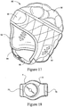
- a respiratory apparatus may comprise a headgear 80 that may take the form of, for example, a skull cap.
- a pair of ear covering portions 82 may be provided as well as a head covering portion 88.
- a head circling band 90 may be provided between the ear covering portions 82 and the head covering portion 88.
- a pair of straps, e.g. chin straps, 84, 86 may be provided to the ear covering portions 82 to secure the headgear 80 to the patient.
- the flow generator may be provided in the headgear 80, for example in the head covering portion 88.
- the power supply e.g. the battery, or batteries, including the flexible cells
- the control electronics e.g. the voltage regulator and/or the motor controller
- the flow generator, the power supply and the control electronics may be encased in foam or other cushioning material to improve the comfort of the headgear.
- the battery cells may be distributed about the headgear 80 to spread the weight of the power supply throughout the headgear to improve comfort, reduce, or minimize the height of the apparatus, and increase, or maximize, the stability of the apparatus.
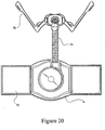
- a respiratory apparatus comprises a flow generator 4 comprising a flow generator housing or casing 6.
- the flow generator 4 may include a blower assembly as previously described.
- the flow generator housing 6 comprises slots 70 configured to receive a band or strap 72 as shown in Fig. 18 .
- the band or strap 72 may be configured to encircle the chest or arm of the patient to support the flow generator 4 at a position spaced from the head of the patient.
- a delivery tube or conduit 74 is configured to be connected to the flow generator 4 at a first end and configured to be connected to a patient interface 10 at a second end.
- the delivery tube or conduit 74 may be a retractable tube or conduit that is flexible and extensible to accommodate movement of the patient's head, and thus movement of the patient interface 10.
- a retractable tube is disclosed in U.S. Application 12/211,896 , filed September 17, 2008.
- the patient interface may be held in contact with the face of the patient by a headgear system 76.
- the band, or strap, 92 may be configured to be integrally formed with the flow generator casing 6.
- the band or strap may be separately formed and passed through the slots 70 in the flow generator casing 6.
- the respiratory apparatus can be segmented into the respective elements.
- the power supply e.g. battery cells or pack
- the control electronics e.g. the voltage regulator and/or motor controller
- the left and/or right of the flow generator casing 6 may be connected by a flexible joint, such as a cable. This permits a more custom fit to the patient.
- the blower assembly housing may differ from the housing disclosed in Figs. 4-16 in that the blower assembly housing may include a single outlet tangential to the blower assembly inlet. It should be appreciated, however, that the sample embodiment shown in Figs. 18-20 may be provided with a pair of outlets, and a pair of delivery tubes or conduits which may deliver the flow of pressurized breathable gas to a patient interface having two inlets, for example an inlet on each side of the patient interface. Such a patient interface is disclosed, for example, in WO 2005/063328 A1 , assigned to ResMed Ltd.
- the flow generator housing 6 may be configured to support the blower assembly 22, the power source 20, e.g. the battery or battery pack, and control circuitry for operation of the electric motor of the blower assembly.
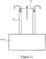
- a variation of the sample embodiment of Figs. 18-20 may include a concentric air inlet tube 78 surrounding the air delivery tube 74. If the flow generator is worn beneath the patient's bed clothes, e.g. pyjamas, the concentric air inlet tube may be placed outside the patient's bed clothes to draw fresh air into the flow generator housing.
- the flow generator may be turned on and off using a switch. It should also be appreciated that the flow generator may be turned on using ResMed's SMART START® control.
- the sample embodiments of the respiratory apparatus disclosed herein may be configured so that the noise level is sufficiently low to allow patients to sleep.
- typical flow generators are often configured such that the sound power emitted is about 25 dB based on testing 1 meter away at the front of the device.
- the sample embodiments of the respiratory apparatus disclosed herein are configured to be placed on the user's person, e.g. on the head, an arm, the chest. This proximity of the flow generator to the user may result in an increased sound level experienced by the user, for example by about 10 dB(A).
- the sample embodiments disclosed herein may include less insulation around the blower assembly of the flow generator, which may further increase the sound level experienced by the user, for example by about another 10 dB(A).
- a flow generator such as that disclosed in U.S. Patent Application Publication 2008/0304986 A1 comprising no insulation emits about 52 dB(A) sound power when running at 10cm H 2 O air pressure.
- the sample embodiments of the respiratory apparatus disclosed herein may comprise insulating material within the headgear, mask, blower assembly, and/or flow generator casing, and/or a muffler, to reduce the sound power emitted.
- the headgear may be configured to reduce the sound power emitted by about 5-10 dB(A).
- the sample embodiments of the respiratory apparatus disclosed herein may emit a sound power of between about 10-100 dB(A), for example about 10-65 dB(A), as another example about 10-50 dB(A), as a further example about 20-40 dB(A), and as an even further example less than about 25 dB(A), when the respiratory apparatus is providing a flow at about 10 cm H 2 O.
- air will be taken to include breathable gases, for example air with supplemental oxygen. It is also acknowledged that the blowers described herein may be designed to pump fluids other than air.
- each individual component of any given assembly, one or more portions of an individual component of any given assembly, and various combinations of components from one or more embodiments may include one or more ornamental design features.
- the invention has particular application to patients who suffer from OSA, it is to be appreciated that patients who suffer from other illnesses (e.g., congestive heart failure, diabetes, morbid obesity, stroke, barriatric surgery, etc.) can derive benefit from the above teachings.
- the above teachings have applicability with patients and non-patients alike in non-medical applications.
Landscapes
- Health & Medical Sciences (AREA)
- Engineering & Computer Science (AREA)
- Pulmonology (AREA)
- Heart & Thoracic Surgery (AREA)
- Life Sciences & Earth Sciences (AREA)
- Veterinary Medicine (AREA)
- Anesthesiology (AREA)
- Biomedical Technology (AREA)
- Public Health (AREA)
- Hematology (AREA)
- Emergency Medicine (AREA)
- Animal Behavior & Ethology (AREA)
- General Health & Medical Sciences (AREA)
- Mechanical Engineering (AREA)
- General Engineering & Computer Science (AREA)
- Otolaryngology (AREA)
- Structures Of Non-Positive Displacement Pumps (AREA)
- Percussion Or Vibration Massage (AREA)
- Respiratory Apparatuses And Protective Means (AREA)
Description
- The present invention relates to a respiratory apparatus for delivering a flow of pressurized breathable gas to a patient.
- Obstructive Sleep Apnea (OSA) is a sleep breathing disorder (SBD). For those who have OSA, when they sleep the soft tissue in their throat and airway relax and collapse thus blocking the airway and preventing airflow to the lungs. This cessation of breathing, known as an apnea, can last for up to one minute before the blood oxygen levels reach a critical point where the patient has an arousal and their airway reopens. Most OSA suffers do not remember these arousals, however each arousal places extra strain on a patient's heart and destroys the quality of their sleep.
- The treatment for OSA may include continuous positive airway pressure (CPAP). CPAP involves the patient wearing a nasal or facemask that delivers positive pressure into the patients airway. This acts as a pneumatic splint and holds the patients airway open to prevent apneas.
- A typical respiratory apparatus for CPAP therapy includes a flow generator, including for example an air blower, that generates a flow of pressurized breathable gas, e.g. air, to a patient interface configured to be worn by the patient in sealing engagement with the patient's face. The patient interface may be, for example, a nasal mask, a full face mask, or nasal pillows. The flow generator and the patient interface are connected by a tube that delivers the flow to the patient interface.
- The typical respiratory apparatus for CPAP therapy has several disadvantages. The patient interface and tube tend to be bulky, and the tube may be rather long, e.g. from about 2-3 m in length. The headgear used to maintain the patient interface in contact with the patient's face may also be bulky and/or complicated to correctly put on and/or adjust. These factors may make a patient reluctant to start CPAP therapy. These factors may also make it difficult for the patient to find a comfortable sleeping position. During sleep, the patient may change position, and the tube may exert a force, i.e. tube drag, on the patient interface which may disrupt the seal between the patient interface and the patient's face. This may result in a leak in the patient interface, which reduces the efficacy of the treatment. Leakage from the patient interface may also irritate the patient, or the patient's sleeping partner, thus further damaging the quality of the patient's sleep.
- Patients using a typical CPAP apparatus for therapy may also find it difficult to travel with the apparatus. The flow generator, tube, and mask may be difficult to pack in luggage, and may take up a lot of room within the luggage. The patient may also find it difficult to use the apparatus away from home as the flow generator typically includes a power cord that must be plugged into a power source, e.g. an AC wall socket, which may not be accessible, or available, at the location the patient is visiting.
- It is therefore an object underlying the present invention to provide an improved flow generator and an improved apparatus for delivering a flow of pressurized breathable gas to a patient. It is a further preferred object underlying the present invention to provide an improved flow generator and an improved apparatus for delivering a flow of pressurized breathable gas to a patient which overcome or reduce the disadvantages of the prior art. Other objects of the present invention will become clear from the further discussion.
- These objects are particularly overcome by the subject-matter of the independent claims. Preferred additional and alternative embodiments are discussed in the following description and the dependent claims.
- One aspect relates to enhancing the treatment delivery by a device that incorporates all, or most, of the components of a CPAP system into a single wearable device. For example, the mask and flow generator may be integrated into a mask system worn by the patient. The flow generator may be incorporated into a headgear configured to support the mask. This aspect provides several advantages over current CPAP systems.
- Another additional or alternative aspect relates to providing a CPAP system that is streamlined, for example by the removal of the flow generator power cable and/or the air delivery tube. According to this aspect, the patient has increased freedom of movement, including during sleep. The elimination of the tube may lead to reduction in leaks due to a reduction in destabilizing forces on the patient interface.
- Yet another additional or alternative aspect relates to reducing the size of a blower in a flow generator blower assembly as a result of lower power requirements, which are possible due to the reduction, or elimination, of head loss in the flow in an air delivery tube.
- A further additional or alternative aspect relates to a CPAP system that is less obtrusive and more intuitive to use for the patient. The CPAP system may be anthropometrically designed to engage the wearer's head and face in a manner readily and easily understood by the patient.
- An even additional or alternative further aspect relates to a CPAP system that is portable and may be used by the patient when away from home. The CPAP system may be configured to contain its own power supply, e.g. a battery or battery pack. The CPAP system may also be configured to be received in a docking station to recharge the power supply.
- Still another additional or alternative aspect relates to a flow generator that is reduced in size compared with stand alone flow generators. The flow generator may be incorporated into a housing that is configured to engage the patient's body, e.g. the patient's chest, arm or head. Such a flow generator may operate on a rechargeable power supply, e.g. a battery or battery pack, for the entirety of the patient's sleep cycle. The flow generator may also generate less noise, and be more efficient, than stand alone flow generators. Preferably, the flow generator, the batteries, the control unit and/or additional electronics of an air delivery apparatus are arranged separately and distinct from one another. Preferably, the flow generator, the batteries, the control unit and/or additional electronics of an air delivery apparatus are arranged in different housings which may be individually arranged on or connected to a patient's body. Preferably, these elements are connected, preferably electrically rather than mechanically, to each other by means of flexible joints, e.g. flexible cables or the like. This particularly allows arrangement of these elements individually and custom fit on a patient, e.g. on a chest band, arm band and/or head gear, such as a skull cap. This minimizes size, height and weight of the assembly and allows distribution of these factors along different portions of a patient's head and/or body.
- According to a sample embodiment, a flow generator for generating a flow of pressurized breathable gas comprises a cylindrical housing and a motor supported in the housing. The motor has a shaft having a first end and a second end opposite the first end. The shaft is generally coincident with an axis of the motor. A first impeller is attached to the first end of the shaft and a second impeller is attached to the second end of the shaft. A stator directs an air flow from the first impeller back towards the motor axis. The stator is preferably arranged, with regard to the axis of the motor, between the first and second impellers. The housing comprises an inlet adjacent the first end of the shaft and having an inlet axis generally coincident with the motor axis, and at least one outlet between, preferably with regard to the axis of the motor, the first and second impellers. The at least one outlet has an outlet axis generally tangential to the motor axis and/or to a circumference of the cylindrical housing. The outlet axis is preferably generally perpendicular to the motor axis.
- According to another sample embodiment, an apparatus for delivering a flow of pressurized breathable gas to a patient comprises a flow generator, preferably according to the present invention, and a casing to contain the flow generator. The casing is configured to engage the a part of the patient's body and preferably the top of the patient's head. The apparatus further comprises at least one and preferably a pair of delivery conduits to convey the flow of pressurized breathable gas and a patient interface to receive the flow of pressurized breathable gas from the pair of delivery conduits and deliver it to the patient's airways.
- According to a further sample embodiment, an apparatus for delivering a flow of pressurized breathable gas to a patient comprises a flow generator, preferably as described above, and a casing to contain the flow generator. The casing is configured to receive a strap adapted to encircle the patient's arm or chest. The apparatus further comprises a at least one delivery conduit to convey the flow of pressurized breathable gas and a patient interface to receive the flow of pressurized breathable gas from the at least one delivery conduit and deliver it to the patient's airways.
- According to another sample embodiment, an apparatus for delivering a flow of pressurized breathable gas to a patient comprises a flow generator, preferably according to the present invention; a casing to contain the flow generator, wherein the casing is configured to engage a part of the patient's body; a power supply for the flow generator; at least one delivery conduit to convey the flow of pressurized breathable gas; and a patient interface to receive the flow of pressurized breathable gas from the at least one delivery conduit and deliver it to the patient's airways.
- Other aspects, features, and advantages will become apparent from the following detailed description when taken in conjunction with the accompanying drawings, which are a part of this disclosure and which illustrate, by wav of example, principles of the invention.
- The accompanying drawings facilitate an understanding of the various embodiments described herein. In such drawings:
-
Fig. 1 schematically illustrates a respiratory apparatus according to a sample embodiment; -
Fig. 2 schematically illustrates a respiratory apparatus according to another sample embodiment; -
Fig. 3 schematically illustrates a flow generator housing or casing for a respiratory apparatus according to a sample embodiment; -
Fig. 4 schematically illustrates a blower assembly of a flow generator for a respiratory apparatus according to a sample embodiment; -
Fig. 5 schematically illustrates a side elevation view of the blower assembly ofFig. 4 ; -
Fig. 6 schematically illustrates an opposite side elevation view of the blower assembly ofFig. 4 ; -
Fig. 7 schematically illustrates a front side election view of the blower assembly ofFig. 4 ; -
Fig. 8 schematically illustrates a bottom view of the blower assembly ofFig. 4 ; -
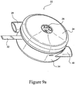
Fig. 9a schematically illustrates a perspective view of the blower assembly ofFig. 4 ; -
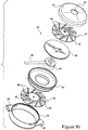
Fig. 9b schematically illustrates an exploded assembly view of the blower assembly ofFig. 9a ; -
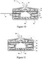
Fig. 10 schematically illustrates a cross-section of the blower assembly ofFig. 4 ; -
Fig. 11 schematically illustrates a cross-section of the blower assembly ofFig. 4 ; -
Fig. 12 schematically illustrates a cross-section of a first impeller of the blower assembly ofFig. 4 ; -
Fig. 13 schematically illustrates a perspective view of the first impeller ofFig. 12 ; -
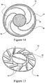
Fig. 14 schematically illustrates a stator of the blower assembly ofFig. 4 ; -
Fig. 15 schematically illustrates a second impeller of the blower assembly ofFig. 4 ; -
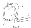
Fig. 16 schematically illustrates a respiratory apparatus according to another sample embodiment; -
Fig. 17 schematically illustrates a respiratory apparatus according to another sample embodiment; -
Fig. 18 schematically illustrates a flow generator according to another sample embodiment; -
Figs. 19 and20 schematically illustrate a respiratory apparatus incorporating the flow generator ofFig. 17 ; and -
Fig. 21 schematically depicts a respiratory apparatus according to another sample embodiment. - The following description is provided in relation to several embodiments which may share common characteristics and features.
- Referring to
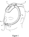
Fig. 1 , a respiratory apparatus for delivering a flow of pressurized breathable gas to apatient 2, for example to treat SBD, such as OSA, comprises aflow generator 4 to generate the flow of pressurized breathable gas. Theflow generator 4 is contained in a flow generator housing orcasing 6 that is anthropometrically configured to engage the head of thepatient 2. As shown inFig. 1 , theflow generator housing 6 is configured to engage the top of the patient's head to permit the patient to sleep on the patient's side without disturbing the positioning of theflow generator housing 6. As shown inFig. 1 , the flow generator housing may have a curvature in the back to front direction of the housing, and a curvature in a lateral direction, i.e. in a direction from one side of the patient's head to the other side. - The
flow generator 4 delivers a flow of pressurized breathable gas through delivery tubes orconduits 8 which are connected to theflow generator housing 6 for receipt of the flow of pressurized breathable gas. The flow of pressurized breathable gas is delivered by thedelivery conduits 8, which extend from theflow generator housing 6 along the sides of the face of thepatient 2, to apatient interface 10 that is in contact with the nasal passageways of thepatient 2. As shown inFig. 1 , thepatient interface 10 may support nasal pillows orprongs 12 which are in sealing contact with the nares of the patient's nose. It should be appreciated, however, that thedelivery conduits 8 may deliver the flow of pressurized breathable gas to a nasal mask which covers only the nose of the patient. As another example, thedelivery conduits 8 may be connected to a full face mask which covers the nose and mouth of the patient. As an even further example, thedelivery conduits 8 may be connected to a patient interface that includes a mouth covering portion having nasal pillows or prongs extending from the mouth covering portion for sealing engagement with the nose of the patient. It should be even further appreciated that the patient interface may include nasal cannulae which do not sealingly engage with the nose of the patient. - The
conduits 8 may be formed of soft material, for example silicone rubber, to isolate vibrations from theflow generator 4. Theconduits 8 may also be connected to the flow generator by a connector configured to isolate vibrations, for example a soft grommet or a bellows type connector. Theconduits 8 may also be the conduits as disclosed inU.S. Patent Application Publication 2008/0060649 A1 .WO2007048205 describes a blower motor with two impellers. - Referring to
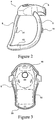
Fig. 2 , a respiratory apparatus according to another sample embodiment includesstrap attachment portions 14 provided on thedelivery conduits 8. A strap, or headgear system, may be connected to the strap attachment portions to provide additional securement of the respiratory apparatus to the head of the patient. As shown inFig. 2 , theflow generator housing 6 may be configured to extend towards the back of the head of thepatient 2, but may not extend as far forward on the head of thepatient 2 as theflow generator housing 6 of the sample embodiment ofFig. 1 . - Referring to
Fig. 3 , theflow generator housing 6 may be configured to support avoltage regulator 16, amotor controller 18 and apower source 20. Thepower source 20 may comprise a battery, or a plurality of batteries. For example, the battery or batteries may be configured as lithium polymer batteries and may have a volumetric energy density of about 250-530 Wh/L, for example about 270 to 400 Wh/l, as another example about 330 Wh/l and a gravimetric energy density of about 150-200 Wh/kg, for example about 155 to 175 Wh/kg, as another example about 163 Wh/kg. Such a battery would have, for example, a battery volume of 112 cm2 and a weight of 225 g. The lithium polymer battery may comprise 32 lithium polymer battery cells that would provide approximately 8 hours of power to an electric motor of a blower assembly of theflow generator 4 for generating a flow of about 40-60 l/min, for example, 50 l/min at a pressure in a range of about 2-12 cm H2O, for example about 6 cm H2O. The battery cells may be flexible and thus may be curved for insertion into thehousing 6 which may be curved to match the shape of the top of the patient's head. - The lithium polymer battery may have a life cycle of approximately 500 charges. The
flow generator housing 4 may be provided with a docking station configured to charge the battery when thehousing 4 is placed in the station. - Referring to
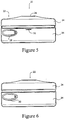
Figs. 4 and5 , theflow generator 4 comprises ablower assembly 22. Theblower assembly 22 comprises a blower assemblyupper housing 24 and a blower assemblylower housing 34. Ablower assembly inlet 26 is provided in theupper housing 24. It should be appreciated that the use of the terms "upper" and "lower" refer to the orientation of the blower assembly housing shown in the drawings and not necessarily to any required orientation of the blower assembly. As shown inFigs. 4-9b , theblower assembly 22 comprises afirst outlet 28 and asecond outlet 30 on opposite sides of thelower housing 34. Anelectrical connector 32 is provided between theupper housing 24 and thelower housing 34 to provide power to an electric motor 44 (Fig. 10 ). - Referring to
Fig. 10 , theblower assembly 22 comprises theupper housing 24 and thelower housing 34 and amiddle housing 40 provided between theupper housing 24 and thelower housing 34. Astator 38 is supported on themiddle housing 40. Theelectric motor 44 is supported by thestator 38. - The
electric motor 44 includes ashaft 45 that extends from opposite sides of theelectric motor 44. Theshaft 45 may be generally coincident with an axis of themotor 44. Afirst impeller 36 is connected to theshaft 45 for rotation with the shaft upon actuation of theelectric motor 44. Asecond impeller 42 is connected to the opposite side of theshaft 45 and thus the opposite side of the motor for rotation with theshaft 45 upon actuation of theelectric motor 44. Themotor 44 may be selected from a variety of commercially available motors, for example from the motors supplied by Maxon Motor of Switzerland. - Upon actuation of the
electric motor 44, theshaft 45 rotates and causes rotation of thefirst impeller 36 and thesecond impeller 42. As shown inFigs. 10 and 11 , rotation of theimpellers inlet 26 of theblower assembly 22. The flow enters theupper housing 24 through theinlet 26 and proceeds around thefirst impeller 36 and is forced down towards thestator 38. The flow then flows around thestator 38 and is forced down through the middle of thesecond housing 40 towards thesecond impeller 42. Thesecond impeller 42 forces the flow back up over the periphery of themiddle housing 40 and out through thefirst outlet 28 and thesecond outlet 30. - The
inlet 26 of theblower assembly 22 has an axis that is generally coincident with the axis of theelectric motor 44. The axis of thefirst outlet 28 and the axis of thesecond outlet 30 are generally tangential to circumference of thehousings blower assembly 22 and/or themotor 44. The use of the axiallycoincident inlet 26, thetangential outlets impellers Figs. 10 and 11 , which utilizes what would otherwise be dead space in the blower assembly and thus reduces the overall size of theblower assembly 22. The reduced size of theblower assembly 22 provides smaller gaps and apertures along the flow path which reduces, or eliminates, turbulence and noise, and enables a low flow Reynolds number for the flow F from theblower assembly 22. Theblower assembly 22 may be adapted such that the path of the flow F extends along a first section from theinlet 26 having an axis that is generally parallel and/or coincident to the axis of theelectric motor 44. The flow F is then directed, along a second section, radially outwardly with regard to the axis of theelectric motor 44 by thefirst impeller 36. The flow F then extends along a third section, from the outer circumference of thefirst impeller 36 in a generally axial direction, and generally parallel and in the same general direction as the flow's initial direction when entering theinlet 26 along the first section. The flow F then extends, along a fourth section, radially inwardly along thestator 38. Accordingly, the flow F is folded back on itself at least once, for example from a radial outward direction around the circumference of thefirst impeller 36 along the second section to a radial inward direction along the fourth section. - The flow F extends radially inwardly along the
stator 38 generally up to the outer circumference of themotor 44. The flow F then extends along a fifth section that extends generally axially with respect to the axis of themotor 44 and along the motor in generally the same direction as the first section. The fifth section of the flow F maybe defined between themotor 44 and the inner circumference of themiddle housing 40. The flow F then extends a long a sixth section and is directed radially outwardly with respect to the axis of themotor 44 by thesecond impeller 42. Accordingly, the flow F is folded back on itself at least once, and possibly a second time, i.e. from a radial inward direction alongstator 38 and along the fourth section to a radial outward direction along thesecond impeller 42 and the sixth section. At the outer circumferential end of thesecond impeller 42 the flow F extends, along a seventh section, generally axially upwardly towards the first and/orsecond outlet Figs. 10 and 11 . As shown, the flow F may be generally radially symmetrical. - The
outlets blower assembly 22 to be reduced, or minimized. The use of elliptical or oval outlets provides a sufficient cross sectional area to permit the flow to exit the blower assembly and also reduces sharp corners in the blower assembly. As shown, for example inFigs. 4 ,8 ,9a , and9b , there are twooutlets blower assembly 22. The use of two symmetrical outlets provides more outlet flow area for a given axial height than a single outlet, and lowers conducted noise. It should be appreciated that more than two outlets may be provided. It should also be appreciated that the outlets may have a 360° rotational symmetry. - Referring to
Fig. 12 , thefirst impeller 36 includes afirst impeller disk 46. Amotor mounting portion 48 is configured for mounting thefirst impeller 36 to theelectric motor shaft 45. As shown inFig. 13 , themotor mounting portion 48 includes anaperture 50 configured to receive theelectric motor shaft 45. A plurality ofvanes 52 are provided on thefirst impeller disk 46 to generate the flow F upon rotation of thefirst impeller 36. Thevanes 52 direct the flow radially to the periphery of thefirst impeller 36 as shown inFigs. 10 and 11 . Thefirst impeller 36 generates a flow F that is initially in the axial direction of theelectric motor 44. - As shown in
Fig. 13 , thevanes 52 of thefirst impeller 36 may be generally straight. However, it should be appreciated that thevanes 52 may be curved. As also shown inFig. 13 , thevanes 52 may have a varying height. The height of the vanes may be largest toward the center of thefirst impeller disk 46 and may be smallest at the outer periphery or circumference of thefirst impeller disk 46. The height of the vanes for 52 may be related to the diameter of thefirst impeller disk 46 for providing a desired flow. The height of thevanes 52 may be optimized for the selected diameter of thefirst impeller disk 46 to further reduce the overall size of theblower assembly 22. Thevanes 52 may be configured such that the height of thevanes 52 at their tips (i.e. at the circumferential edge of the disk 46) are the minimum height that does not choke the flow F. The "choke" is related to the cylindrical surface of thedisk 46 at the circumferential edge, i.e. the outer edges of thevanes 52, and the axial height of thevanes 52 at the circumferential edge of thedisk 46. In other words the "choke" is related to a cylinder of diameter equal to the outer diameter ofdisk 46 and which has an axial dimension (height) equal to the height of thevanes 52 at the periphery ofdisk 46. The lower the height of thevanes 52, the lower the Reynolds number and therefore the lower the turbulence noise. - Referring to
Fig. 14 , thestator 38 comprises astator disk 54 and amotor mounting portion 56 to mount thestator 38 to theelectric motor 44. A plurality ofvanes 58 are provided on thestator disk 54. As shown inFig. 14 , thevanes 58 are curved to fold the flow F delivered from thefirst impeller 36 back towards the center of the blower assembly, i.e. back toward theelectric motor 44. Thevanes 58 then direct the flow F in the direction of the axis of theelectric motor 44 through themiddle housing 40 toward thesecond impeller 42, as shown inFigs. 10 and 11 . - Referring to
Fig. 15 , thesecond impeller 42 comprises asecond impeller disk 60 and amotor mounting portion 62 configured to connect thesecond impeller 42 to theshaft 45 of theelectric motor 44. A plurality ofvanes 64 are provided on thesecond impeller disk 62 for directing the flow F around themiddle housing 40 and out thefirst outlet 28 and asecond outlet 30, as shown inFigs. 10 and 11 . By folding the flow F back toward theelectric motor 44, and by directing it axially along the circumference of theelectric motor 44 before folding the flow F back, radially outwardly be thesecond impeller 42, the flow F cools themotor 44 and is heated by passing themotor 44. Thevanes 64 of thesecond impeller disk 62 may be configured in a manner similar to thevanes 52 of thefirst impeller disk 46. As shown inFigs. 9b ,10 and 11 , the inner ends of thevanes 64 define a diameter that is larger than the diameter of themotor 44. This allows thevanes 64 to sit, at least partly, at the same axial position as the lower section of themotor 44, which reduces the axial height of theblower assembly 22. - The blower assembly may have a width of about 45-60 mm, for example about 50-55 mm, as another example about 52 mm, and a height of about 20-30 mm, for example about 23-27 mm, as another example about 25 mm. The motor may have a width of about 15-25 mm, for example about 17-23 mm, as another example about 20 mm, and a height of about 15-20 mm, for example about 17 mm. The motor may be brushless and deliver about 1-5 W shaft power, for example about 3 W. The motor may weigh about 10-20 g, for example about 13-17 g, as another example about 15 g. The blower assembly may provide a flow of about 40-60 l/min., for example about 45-55 l/min, as another example about 50 l/min., at a pressure of about 2-12 cm H2O, for example about 4-8 cm H2O, as another example about 6 cm H2O. It should be appreciated that these flow and pressure ranges are examples and the flow generator may be scaled to provide flow and pressure ranges other than the examples provided herein.
- The housing of the blower assembly may be configured to suppress noise generated by the
motor 44. For example, a gel layer may be provided between theupper housing 24 and thelower housing 34, and/or a gel layer may be provided between thestator 38 and themotor 44 to damp vibrations and/or noise generated by themotor 44. - Other modifications that may be made to the blower assembly include providing bearings to the
housing motor 44, as disclosed inU.S. Patent Application Publication 2008/0304986 A1 adding a magnet(s) to the impeller(s), and/or configuring the motor as an axial gap motor, for example as disclosed inWO 2007/134405 A1 . - It should also be appreciated that other flow generator and blower assemblies may be used in the sample embodiments discussed herein. For example, the flow generator and blower assemblies disclosed in
U.S. Applications 29/274,504 29/274,505 29/274,506 WO 2007/048206 A1 may be used. As another example, the flow generator and blower assemblies disclosed inU.S. Applications 29/274,504 ,29/274,505 29/274,506, filed April 27, 2007 WO 2007/048205 A1 may be used. - Referring to
Fig. 16 , a respiratory apparatus according to another sample embodiment comprises aflow generator 4 provided in aflow generator housing 6 configured to engage the head of the patient, for example the crown of the patient's head. Theflow generator 4 is configured to deliver a flow of pressurized breathable gas todelivery conduits 8 which are configured to extend from the flow generator along the sides of the face of the patient to apatient interface 10. The patient interface may include nasal pillows or prongs, a nasal mask, a full face mask, or cannulae. - Power is provided to the
flow generator 4 by a power supply andcontroller 66 that is connected to theflow generator 4 by anelectrical connector 68, for example a cable. The power supply/controller 66 may be configured to be docked in a battery charger, or may include an attachment that allows for charging of the power supply and controller from a voltage source, for example a common household 120 volt AC socket, or a 12 volt car battery charging outlet. The remaining configuration and features of the flow generator and blower assembly, respectively, may correspond to those discussed and shown with respect to the preceding and following embodiments. - Referring to
Fig. 17 , a respiratory apparatus according to another sample embodiment may comprise aheadgear 80 that may take the form of, for example, a skull cap. A pair ofear covering portions 82 may be provided as well as ahead covering portion 88. Ahead circling band 90 may be provided between theear covering portions 82 and thehead covering portion 88. A pair of straps, e.g. chin straps, 84, 86 may be provided to theear covering portions 82 to secure theheadgear 80 to the patient. - The flow generator may be provided in the
headgear 80, for example in thehead covering portion 88. The power supply (e.g. the battery, or batteries, including the flexible cells) and the control electronics (e.g. the voltage regulator and/or the motor controller) may also be provided in theheadgear 80, for example in thehead covering portion 88 or the ear covering portion(s) 82. The flow generator, the power supply and the control electronics may be encased in foam or other cushioning material to improve the comfort of the headgear. The battery cells may be distributed about theheadgear 80 to spread the weight of the power supply throughout the headgear to improve comfort, reduce, or minimize the height of the apparatus, and increase, or maximize, the stability of the apparatus. - Referring to
Figs. 18-20 , a respiratory apparatus according to another sample embodiment comprises aflow generator 4 comprising a flow generator housing orcasing 6. Theflow generator 4 may include a blower assembly as previously described. Theflow generator housing 6 comprisesslots 70 configured to receive a band orstrap 72 as shown inFig. 18 . The band orstrap 72 may be configured to encircle the chest or arm of the patient to support theflow generator 4 at a position spaced from the head of the patient. A delivery tube orconduit 74 is configured to be connected to theflow generator 4 at a first end and configured to be connected to apatient interface 10 at a second end. The delivery tube orconduit 74 may be a retractable tube or conduit that is flexible and extensible to accommodate movement of the patient's head, and thus movement of thepatient interface 10. Such a retractable tube is disclosed inU.S. Application 12/211,896headgear system 76. - As shown in
Fig. 19 , the band, or strap, 92 may be configured to be integrally formed with theflow generator casing 6. Alternatively, the band or strap may be separately formed and passed through theslots 70 in theflow generator casing 6. The respiratory apparatus can be segmented into the respective elements. For example, the power supply (e.g. battery cells or pack) and the control electronics (e.g. the voltage regulator and/or motor controller) may be located to the left and/or right of theflow generator casing 6 and connected by a flexible joint, such as a cable. This permits a more custom fit to the patient. - As shown in
Figures 19 and20 , the blower assembly housing may differ from the housing disclosed inFigs. 4-16 in that the blower assembly housing may include a single outlet tangential to the blower assembly inlet. It should be appreciated, however, that the sample embodiment shown inFigs. 18-20 may be provided with a pair of outlets, and a pair of delivery tubes or conduits which may deliver the flow of pressurized breathable gas to a patient interface having two inlets, for example an inlet on each side of the patient interface. Such a patient interface is disclosed, for example, inWO 2005/063328 A1 , assigned to ResMed Ltd. - The
flow generator housing 6 may be configured to support theblower assembly 22, thepower source 20, e.g. the battery or battery pack, and control circuitry for operation of the electric motor of the blower assembly. - Referring to
Fig. 21 , a variation of the sample embodiment ofFigs. 18-20 may include a concentricair inlet tube 78 surrounding theair delivery tube 74. If the flow generator is worn beneath the patient's bed clothes, e.g. pyjamas, the concentric air inlet tube may be placed outside the patient's bed clothes to draw fresh air into the flow generator housing. - In the sample embodiments described above, the flow generator may be turned on and off using a switch. It should also be appreciated that the flow generator may be turned on using ResMed's SMART START® control.
- The sample embodiments of the respiratory apparatus disclosed herein may be configured so that the noise level is sufficiently low to allow patients to sleep. In general, typical flow generators are often configured such that the sound power emitted is about 25 dB based on testing 1 meter away at the front of the device. However, the sample embodiments of the respiratory apparatus disclosed herein are configured to be placed on the user's person, e.g. on the head, an arm, the chest. This proximity of the flow generator to the user may result in an increased sound level experienced by the user, for example by about 10 dB(A). In addition, the sample embodiments disclosed herein may include less insulation around the blower assembly of the flow generator, which may further increase the sound level experienced by the user, for example by about another 10 dB(A). For comparison, a flow generator such as that disclosed in
U.S. Patent Application Publication 2008/0304986 A1 comprising no insulation emits about 52 dB(A) sound power when running at 10cm H2O air pressure. - The sample embodiments of the respiratory apparatus disclosed herein may comprise insulating material within the headgear, mask, blower assembly, and/or flow generator casing, and/or a muffler, to reduce the sound power emitted. For example, the headgear may be configured to reduce the sound power emitted by about 5-10 dB(A). The sample embodiments of the respiratory apparatus disclosed herein may emit a sound power of between about 10-100 dB(A), for example about 10-65 dB(A), as another example about 10-50 dB(A), as a further example about 20-40 dB(A), and as an even further example less than about 25 dB(A), when the respiratory apparatus is providing a flow at about 10 cm H2O.
- In this specification, the word "comprising" is to be understood in its "open" sense, that is, in the sense of "including", and thus not limited to its "closed" sense, that is the sense of "consisting only of'. A corresponding meaning is to be attributed to the corresponding words "comprise", "comprised" and "comprises" where they appear.
- The term "air" will be taken to include breathable gases, for example air with supplemental oxygen. It is also acknowledged that the blowers described herein may be designed to pump fluids other than air.
- While the invention has been described in connection with what are presently considered to be the most practical and preferred embodiments, it is to be understood that the invention is not to be limited to the disclosed embodiments, but on the contrary, is intended to cover various modifications and equivalent arrangements included within the scope of the invention. Also, the various embodiments described above may be implemented in conjunction with other embodiments, e.g., aspects of one embodiment may be combined with aspects of another embodiment to realize yet other embodiments. Further, each independent feature or component of any given assembly may constitute an additional embodiment.
- Furthermore, each individual component of any given assembly, one or more portions of an individual component of any given assembly, and various combinations of components from one or more embodiments may include one or more ornamental design features. In addition, while the invention has particular application to patients who suffer from OSA, it is to be appreciated that patients who suffer from other illnesses (e.g., congestive heart failure, diabetes, morbid obesity, stroke, barriatric surgery, etc.) can derive benefit from the above teachings. Moreover, the above teachings have applicability with patients and non-patients alike in non-medical applications.
Claims (19)
- A flow generator (4) for generating a flow of pressurized breathable gas, comprising:a cylindrical housing (24, 34);a motor (44) supported in the housing (24, 34), the motor (44) having a shaft (45) having a first end and a second end opposite the first end, the shaft (45) being generally coincident with an axis of the motor (44);a first impeller (36) attached to the first end of the shaft (45);a second impeller (42) attached to the second end of the shaft (45); anda stator (38) that directs the flow of breathable gas from the first impeller back towards the motor axis, andwherein the housing (24, 34) comprises an inlet (26) adjacent the first end of the shaft (45) and having an inlet axis generally coincident with the motor axis, and at least one outlet (28, 30) between the first and second impellers (36, 42), the at least one outlet (28, 30) having an outlet axis generally tangential to a circumference of the cylindrical housing (24, 34),
wherein the flow generator is configured for the generated flow of breathable gas to enter the first impeller (36) and the second impeller (42) in the same direction. - A flow generator according to claim 1, wherein the cylindrical housing (24, 34) comprises a first cylindrical housing segment (24) and a second cylindrical housing segment (34) and the inlet (26) is provided in the first cylindrical housing segment (24) and the at least one outlet (28, 30) is provided in the second cylindrical housing segment (34).
- A flow generator according to claim 1 or claim 2, wherein the stator (38) and the first and second impellers (36, 42) comprise straight vanes (52) or curved vanes (58).
- A flow generator according to claim 3, wherein the vanes (52, 58) have a varying height and a height of the vanes (52, 58) of the first impeller (36) at a circumferential edge of the first impeller (36) is a minimum height that does not choke the flow (F) of breathable gas.
- A flow generator according to any one of claims 2 to 4, further comprising:
a third housing segment (40) intermediate the first and second housing segments (24, 34), wherein the stator (38) is supported by the third housing segment (40) and the motor (44) is supported by the stator (38). - A flow generator according to any one of claims 1 to 5, wherein the second impeller (42) forces the breathable gas to flow back up toward the at least one outlet.
- A flow generator according to any one of claims 2 to 6, further comprising noise and/or vibration dampening material between the first and second housing segments (24, 34) and/or between the motor (44) and the stator (38).
- A flow generator according to any one of claims 1 to 7, wherein the motor (44) is a brushless motor or an axial gap motor.
- A flow generator according to any one of claims 1 to 8, further comprising a magnet attached to at least one of the first impeller and the second impeller.
- A flow generator according to any one of claims 1 to 9, wherein the flow generator is configured to generate a flow of about 40-60 l/min, for example about 50 l/min.
- A flow generator according to any one of claims 1 to 10, wherein the flow generator is configured to generate a pressure of about 2-12 cm H2O, for example about 6 cm H2O.
- A flow generator according to any one of claims 1 to 11, wherein the at least one outlet comprises two outlets.
- A flow generator according to any one of claims 1 to 12, wherein the stator (38) is arranged with regard to the axis of the motor (44) between the first and second impeller.
- An apparatus for delivering a flow of pressurized breathable gas to a patient, comprising:a flow generator according to any one of claims 1 to 13;a casing (6) to contain the flow generator, wherein the casing is configured to engage a part of the patient's body;a power supply (20, 66) for the flow generator;at least one delivery conduit (8, 74) to convey the flow of pressurized breathable gas; anda patient interface (10) to receive the flow of pressurized breathable gas from the at least one delivery conduit and deliver it to the patient's airways.
- An apparatus according to claim 14, wherein the casing (6) has a curvature in the back to front direction of the casing and a curvature in the lateral direction.
- An apparatus according to claim 14 or claim 15, wherein the casing (6) is configured to receive a strap adapted to encircle the patient's arm or chest.
- An apparatus according to claim 14 or claim 15, wherein the casing (6) is configured to engage the top of the patient's head.
- An apparatus according to any one of claims 14 to 17, wherein the power supply (20) comprises a rechargeable battery comprising at least one and preferably a plurality of flexible battery cells.
- An apparatus according to any one of claims 14 to 18, further comprising a controller (16), for example a voltage regulator, to control the power supply (20).
Priority Applications (1)
| Application Number | Priority Date | Filing Date | Title |
|---|---|---|---|
| EP20170508.4A EP3736005B1 (en) | 2008-01-31 | 2009-01-30 | Respiratory apparatus |
Applications Claiming Priority (2)
| Application Number | Priority Date | Filing Date | Title |
|---|---|---|---|
| US2499308P | 2008-01-31 | 2008-01-31 | |
| EP09001343.4A EP2085106B1 (en) | 2008-01-31 | 2009-01-30 | Respiratory apparatus |
Related Parent Applications (1)
| Application Number | Title | Priority Date | Filing Date |
|---|---|---|---|
| EP09001343.4A Division EP2085106B1 (en) | 2008-01-31 | 2009-01-30 | Respiratory apparatus |
Related Child Applications (1)
| Application Number | Title | Priority Date | Filing Date |
|---|---|---|---|
| EP20170508.4A Division EP3736005B1 (en) | 2008-01-31 | 2009-01-30 | Respiratory apparatus |
Publications (2)
| Publication Number | Publication Date |
|---|---|
| EP3305353A1 EP3305353A1 (en) | 2018-04-11 |
| EP3305353B1 true EP3305353B1 (en) | 2020-04-22 |
Family
ID=40578040
Family Applications (3)
| Application Number | Title | Priority Date | Filing Date |
|---|---|---|---|
| EP20170508.4A Active EP3736005B1 (en) | 2008-01-31 | 2009-01-30 | Respiratory apparatus |
| EP09001343.4A Active EP2085106B1 (en) | 2008-01-31 | 2009-01-30 | Respiratory apparatus |
| EP17181906.3A Active EP3305353B1 (en) | 2008-01-31 | 2009-01-30 | Respiratory apparatus |
Family Applications Before (2)
| Application Number | Title | Priority Date | Filing Date |
|---|---|---|---|
| EP20170508.4A Active EP3736005B1 (en) | 2008-01-31 | 2009-01-30 | Respiratory apparatus |
| EP09001343.4A Active EP2085106B1 (en) | 2008-01-31 | 2009-01-30 | Respiratory apparatus |
Country Status (6)
| Country | Link |
|---|---|
| US (5) | US8667962B2 (en) |
| EP (3) | EP3736005B1 (en) |
| JP (2) | JP5737827B2 (en) |
| CN (4) | CN104189979A (en) |
| AU (1) | AU2009200357B2 (en) |
| NZ (4) | NZ574584A (en) |
Families Citing this family (59)
| Publication number | Priority date | Publication date | Assignee | Title |
|---|---|---|---|---|
| WO2007117716A2 (en) | 2006-04-10 | 2007-10-18 | Aeiomed, Inc. | Apparatus and methods for administration of positive airway pressure therapies |
| EP3736005B1 (en) | 2008-01-31 | 2024-02-28 | ResMed Pty Ltd | Respiratory apparatus |
| WO2010080709A1 (en) | 2009-01-08 | 2010-07-15 | Hancock Medical | Self-contained, intermittent positive airway pressure systems and methods for treating sleep apnea, snoring, and other respiratory disorders |
| US10238822B2 (en) | 2009-05-29 | 2019-03-26 | Resmed Limited | PAP system |
| NZ598152A (en) | 2009-08-28 | 2014-02-28 | Resmed Ltd | Pap system |
| EP2490739A1 (en) * | 2009-10-20 | 2012-08-29 | Deshum Medical, LLC | Integrated positive airway pressure apparatus |
| CN107989814B (en) | 2009-11-19 | 2020-07-07 | 瑞思迈发动机及马达技术股份有限公司 | Blower fan |
| EP2555849B1 (en) * | 2010-04-06 | 2018-06-27 | 3M Innovative Properties Company | Air filtration device |
| EP2608835A4 (en) * | 2010-08-27 | 2018-03-28 | ResMed Limited | Pap system |
| US20120167879A1 (en) * | 2011-01-03 | 2012-07-05 | Bowman Bruce R | Positive airway pressure therapy apparatus and methods |
| US8327846B2 (en) | 2011-02-08 | 2012-12-11 | Hancock Medical, Inc. | Positive airway pressure system with head position control |
| US20150128949A1 (en) * | 2011-02-11 | 2015-05-14 | Koninklijke Philips | Patient interface device having headgear providing integrated gas flow and delivery |
| WO2012113027A1 (en) * | 2011-02-25 | 2012-08-30 | Resmed Motor Technologies Inc. | Blower and pap system |
| FR2973846B1 (en) * | 2011-04-11 | 2013-05-24 | Airfan | APPARATUS FOR REGULATED DELIVERY OF GAS, ESPECIALLY RESPIRATORY ASSISTANCE APPARATUS |
| US9789273B2 (en) | 2011-05-13 | 2017-10-17 | Koninklijke Philips N.V. | Sensor and valve integrated into a patient interface |
| EP3323458B1 (en) * | 2011-06-21 | 2022-08-31 | ResMed Pty Ltd | Pap system |
| US10137264B2 (en) * | 2011-07-13 | 2018-11-27 | Fisher & Paykel Healthcare Limited | Respiratory assistance apparatus |
| US10286167B2 (en) | 2011-07-13 | 2019-05-14 | Fisher & Paykel Healthcare Limited | Impeller and motor assembly |
| US8873170B2 (en) | 2011-07-15 | 2014-10-28 | Honeywell International Inc. | Replacement lens cartridge |
| JP2013150684A (en) * | 2012-01-25 | 2013-08-08 | Nidec Copal Electronics Corp | Cpap device |
| EP2817518B1 (en) | 2012-02-02 | 2020-05-20 | imtmedical ag | Sound-proofing housing for a respirator |
| EP3865169A1 (en) * | 2012-02-02 | 2021-08-18 | Fisher & Paykel Healthcare Limited | Respiratory assistance apparatus |
| CN104394920B (en) * | 2012-03-06 | 2017-03-01 | 瑞思迈发动机及马达技术股份有限公司 | Flow generator |
| CN102872511B (en) * | 2012-10-03 | 2014-12-10 | 王秋华 | Miniature nostril air feeder |
| US9192796B2 (en) | 2012-10-25 | 2015-11-24 | Honeywell International Inc. | Method of donning and testing abrasive blast respirator |
| US9192794B2 (en) | 2012-10-25 | 2015-11-24 | Honeywell International Inc. | Noise reduction system for supplied air respirator |
| US9162088B2 (en) | 2012-10-25 | 2015-10-20 | Honeywell International Inc. | Method of assembly and disassembly of abrasive blast respirator |
| US9192793B2 (en) | 2012-10-25 | 2015-11-24 | Honeywell International Inc. | Abrasive blast respirator |
| CA2893292A1 (en) * | 2012-12-14 | 2014-06-19 | Estill Medical Technologies, Inc. | Wearable in-line fluid warmer and battery combination |
| DE212013000256U1 (en) | 2012-12-18 | 2015-07-22 | Fisher & Paykel Healthcare Ltd. | Impeller and rotor assembly |
| US9289573B2 (en) | 2012-12-28 | 2016-03-22 | Covidien Lp | Ventilator pressure oscillation filter |
| CN103054708B (en) * | 2013-01-11 | 2014-10-08 | 湖南纳雷科技有限公司 | Obstructive sleep apnea therapy apparatus |
| WO2014117179A1 (en) | 2013-01-28 | 2014-07-31 | Hancock Medical, Inc. | Position control devices and methods for use with positive airway pressure systems |
| US20150306324A1 (en) * | 2014-04-29 | 2015-10-29 | Arturo Alejo Ayon | Self-contained continuous positive airway pressure mask and method of use |
| EP2942075A1 (en) * | 2014-05-07 | 2015-11-11 | Mindray Medical Sweden AB | Device and method for a low resistance valve |
| US10881829B2 (en) | 2014-08-18 | 2021-01-05 | Resmed Inc. | Portable pap device with humidification |
| CN107073237A (en) * | 2014-11-19 | 2017-08-18 | 皇家飞利浦有限公司 | Strap member for patient interface |
| JP7188884B2 (en) * | 2014-12-04 | 2022-12-13 | レスメド・プロプライエタリー・リミテッド | Wearable device for air delivery |
| CN104473710B (en) * | 2015-01-05 | 2016-04-06 | 张希龙 | Magnetic suspension Lower jaw support snore stopper |
| US10953188B2 (en) * | 2015-01-09 | 2021-03-23 | Fisher & Paykel Healthcare Limited | Gas therapy system |
| CN105879170A (en) * | 2015-01-21 | 2016-08-24 | 深圳市沃森空调技术有限公司 | Wearable intelligent aerator |
| WO2016141210A1 (en) | 2015-03-03 | 2016-09-09 | Valley Children's Healthcare | Cranium cuddler |
| USD776802S1 (en) | 2015-03-06 | 2017-01-17 | Hancock Medical, Inc. | Positive airway pressure system console |
| EP4186548A1 (en) | 2015-04-02 | 2023-05-31 | Hill-Rom Services PTE. LTD. | Mask leakage detection for a respiratory device |
| ES2585851B1 (en) * | 2015-04-07 | 2017-06-14 | Tecnicas Biomedicas Para La Salud, S.L. | AIR DRIVING DEVICE FOR PROVIDING ASSISTED VENTILATION DURING SPONTANEOUS BREATHING |
| EP3365054B1 (en) * | 2015-10-23 | 2022-05-04 | Fisher & Paykel Healthcare Limited | Apparatus for providing a flow of air to a user |
| CA3022511A1 (en) | 2016-05-04 | 2017-11-09 | Fisher & Paykel Healthcare Limited | Respiratory support system and blower for respiratory support system |
| JP6346914B2 (en) * | 2016-05-13 | 2018-06-20 | アトムメディカル株式会社 | Breathing gas supply device |
| JP2019518520A (en) | 2016-05-19 | 2019-07-04 | ハンコック メディカル, インコーポレイテッド | Position obstructive sleep apnea detection system |
| JP6999668B2 (en) * | 2016-07-25 | 2022-01-18 | レスメド・プロプライエタリー・リミテッド | Respiratory pressure treatment system |
| CN106247257A (en) * | 2016-07-29 | 2016-12-21 | 辉能(天津)科技发展有限公司 | A kind of intelligent medical illumination head lamp |
| CN111033067B (en) | 2017-04-23 | 2022-01-14 | 费雪派克医疗保健有限公司 | Breathing assistance apparatus |
| DE102017007663B4 (en) | 2017-08-14 | 2022-12-29 | Rodenstock Gmbh | Method and device for calculating or evaluating a spectacle lens for an eye of a spectacle wearer, taking into account a vision model, corresponding computer program product, and method and device for producing a spectacle lens |
| US11156224B2 (en) * | 2017-10-10 | 2021-10-26 | Tti (Macao Commercial Offshore) Limited | Backpack blower |
| JP6879432B2 (en) * | 2018-03-30 | 2021-06-02 | 株式会社村田製作所 | CPAP device |
| JP7015963B2 (en) | 2018-08-20 | 2022-02-15 | レスメド・プロプライエタリー・リミテッド | Headgear for patient interface |
| CN116892526A (en) * | 2020-05-15 | 2023-10-17 | 佛山市顺德区美的洗涤电器制造有限公司 | Centrifugal fan and electrical equipment |
| GB2597292B (en) * | 2020-07-20 | 2024-08-14 | Bae Systems Plc | Vibration decoupler |
| GB2622049A (en) * | 2022-08-31 | 2024-03-06 | Dyson Technology Ltd | A compressor and air purifier |
Family Cites Families (68)
| Publication number | Priority date | Publication date | Assignee | Title |
|---|---|---|---|---|
| US3822698A (en) * | 1973-01-22 | 1974-07-09 | R Guy | Powered air-purifying respirator helmet |
| JPS5470108U (en) * | 1977-10-28 | 1979-05-18 | ||
| JPS5849186B2 (en) | 1977-11-14 | 1983-11-02 | 株式会社片岡機械製作所 | Plate cylinder support device for rotogravure printing presses |
| US4233972A (en) * | 1978-05-08 | 1980-11-18 | Wolfgang Hauff | Portable air filtering and breathing assist device |
| US4297999A (en) * | 1979-07-19 | 1981-11-03 | Kitrell John V | Portable resuscitation apparatus |
| WO1982003548A1 (en) | 1981-04-24 | 1982-10-28 | Sullivan Colin Edward | Device for treating snoring sickness |
| US4430995A (en) | 1981-05-29 | 1984-02-14 | Hilton Joseph R | Power assisted air-purifying respirators |
| US4653976A (en) * | 1982-09-30 | 1987-03-31 | General Electric Company | Method of compressing a fluid flow in a multi stage centrifugal impeller |
| US4590951A (en) * | 1983-06-07 | 1986-05-27 | Racal Safety Limited | Breathing apparatus |
| AU4275385A (en) | 1984-06-06 | 1985-12-12 | Racal Safety Ltd. | Respirators fan-assisted |
| GB8721040D0 (en) * | 1987-09-08 | 1987-10-14 | Chapman & Smith Ltd | Respirators |
| GB2215216B (en) | 1988-03-01 | 1991-12-18 | Sabre Safety Ltd | Positive pressure breathing apparatus |
| FR2680467B1 (en) * | 1991-08-21 | 1997-04-04 | Intertechnique Sa | RESPIRATORY PROTECTION EQUIPMENT AGAINST POLLUTANTS. |
| DE4133235A1 (en) * | 1991-10-07 | 1993-04-08 | Draegerwerk Ag | FAN-SUPPORTED BREATHING DEVICE WITH AN ADD-ON CONTROL UNIT |
| US5372130A (en) * | 1992-02-26 | 1994-12-13 | Djs&T Limited Partnership | Face mask assembly and method having a fan and replaceable filter |
| US5538000A (en) * | 1995-02-06 | 1996-07-23 | Hans Rudolph, Inc. | Airflow delivery system |
| US6513526B2 (en) * | 1996-07-26 | 2003-02-04 | Resmed Limited | Full-face mask and mask cushion therefor |
| US6561191B1 (en) * | 1997-02-10 | 2003-05-13 | Resmed Limited | Mask and a vent assembly therefor |
| AUPO504597A0 (en) * | 1997-02-10 | 1997-03-06 | Resmed Limited | A mask and a vent assembly therefor |
| EP1019129A1 (en) | 1997-09-18 | 2000-07-19 | Caradyne (R & D) Limited | Portable respirator |
| US20030062045A1 (en) * | 1998-09-18 | 2003-04-03 | Respironics, Inc. | Medical ventilator |
| US8701664B2 (en) * | 1998-11-06 | 2014-04-22 | Caradyne (R&D) Limited | Apparatus and method for relieving dyspnoea |
| JP3475174B2 (en) * | 2000-02-10 | 2003-12-08 | 東芝テック株式会社 | Electric pump |
| US6772762B2 (en) * | 2000-05-24 | 2004-08-10 | Gregory Hubert Piesinger | Personal powered air filtration, sterilization, and conditioning system |
| US6986352B2 (en) * | 2000-06-22 | 2006-01-17 | Resmed Limited | Mask with gusset |
| US6435184B1 (en) * | 2000-09-01 | 2002-08-20 | Tien Lu Ho | Gas mask structure |
| DE20015791U1 (en) * | 2000-09-12 | 2001-02-15 | Dräger Aerospace GmbH, 23558 Lübeck | Device for supplying breathing gas to a parachutist |
| US20020119044A1 (en) * | 2001-02-26 | 2002-08-29 | O'connor, John F. | Centrifugal blower with partitioned scroll diffuser |
| JP4264619B2 (en) * | 2001-10-12 | 2009-05-20 | 山本光学株式会社 | Respiratory protection |
| CN101450237B (en) * | 2001-12-10 | 2012-03-28 | 雷斯梅德有限公司 | Double-ended blower and volutes therefor |
| US8517012B2 (en) * | 2001-12-10 | 2013-08-27 | Resmed Limited | Multiple stage blowers and volutes therefor |
| US6910483B2 (en) * | 2001-12-10 | 2005-06-28 | Resmed Limited | Double-ended blower and volutes therefor |
| DE10210878B4 (en) * | 2002-03-12 | 2018-01-04 | Drägerwerk AG & Co. KGaA | Apparatus for breathing support |
| JP2004019605A (en) * | 2002-06-19 | 2004-01-22 | Matsushita Electric Ind Co Ltd | Fluid transportation system and its method |
| US7156096B2 (en) * | 2002-07-15 | 2007-01-02 | Landis Robert M | Dynamic infant nasal CPAP system and method |
| EP1558321B1 (en) * | 2002-11-06 | 2016-07-13 | ResMed Limited | Mask and components thereof |
| US20040226562A1 (en) * | 2002-12-06 | 2004-11-18 | Bordewick Steven S. | Blower assembly for CPAP |
| DE10261602A1 (en) | 2002-12-28 | 2004-07-08 | Yamamoto Kogaku Co., Ltd. | Respirator for use in the presence of toxic gas or dust-laden environment has two air filters incorporating electric blower fans |
| CN101496926B (en) * | 2003-02-21 | 2015-01-21 | 瑞思迈有限公司 | Nasal assembly |
| AU2004244672B2 (en) | 2003-06-10 | 2011-02-10 | Resmed Limited | Multiple stage blower and enclosure therefor |
| AU2003903139A0 (en) * | 2003-06-20 | 2003-07-03 | Resmed Limited | Breathable gas apparatus with humidifier |
| FR2856930B1 (en) * | 2003-07-04 | 2007-09-07 | Saime Sarl | MODULAR TURBINE BREATHING AIDING DEVICE. |
| CN1859940B (en) * | 2003-09-25 | 2010-06-16 | 雷斯梅德有限公司 | Ventilator mask and system |
| JP2005171825A (en) * | 2003-12-09 | 2005-06-30 | Ebara Corp | Fluid conveyance machine |
| ES2530393T3 (en) | 2003-12-31 | 2015-03-02 | Resmed Ltd | Nozzle for a buconasal patient interface |
| US6889689B1 (en) * | 2004-01-06 | 2005-05-10 | Deborah W. Neuman | Bubble CPAP cap for neonates |
| GB0402625D0 (en) * | 2004-02-06 | 2004-03-10 | Boc Group Plc | Vibration damper |
| JP4592314B2 (en) | 2004-03-26 | 2010-12-01 | 株式会社東芝 | Fluid pump, electrical equipment and cooling device |
| WO2006045602A1 (en) * | 2004-10-26 | 2006-05-04 | Map Medizin-Technologie Gmbh | Apparatus for administering a breathable gas, and components thereof |
| US20060096596A1 (en) * | 2004-11-05 | 2006-05-11 | Occhialini James M | Wearable system for positive airway pressure therapy |
| US20070000493A1 (en) * | 2005-06-01 | 2007-01-04 | Cox Kingsley J | Apparatus for maintaining airway patency |
| DE102005031388B4 (en) * | 2005-07-05 | 2017-05-04 | Resmed Limited | Device for conveying a respiratory gas |
| US7937775B2 (en) * | 2005-08-09 | 2011-05-10 | Microtek Medical, Inc. | Surgical protective head gear assembly including high volume air delivery system |
| JP2007078259A (en) | 2005-09-14 | 2007-03-29 | Japan Vilene Co Ltd | Fan filter unit |
| JP5186379B2 (en) | 2005-10-28 | 2013-04-17 | レスメド・リミテッド | Single stage or multistage blower and nested vortex chamber and / or impeller for the vortex chamber |
| US7748381B2 (en) * | 2005-12-09 | 2010-07-06 | 3M Innovative Properties Company | Portable blower system |
| WO2007117716A2 (en) * | 2006-04-10 | 2007-10-18 | Aeiomed, Inc. | Apparatus and methods for administration of positive airway pressure therapies |
| US7516743B2 (en) * | 2006-04-20 | 2009-04-14 | Viasys Sleep Systems, Llc | Continuous positive airway pressure device and configuration for employing same |
| US20070251527A1 (en) * | 2006-04-21 | 2007-11-01 | Tiara Medical Systems, Inc. | Self-contained respiratory therapy apparatus for enhanced patient compliance and therapeutic efficacy |
| WO2007134405A1 (en) | 2006-05-24 | 2007-11-29 | Resmed Ltd | Compact low noise efficient blower for cpap devices |
| EP2051760B1 (en) * | 2006-07-28 | 2014-03-12 | ResMed Limited | Patient interface |
| WO2008011682A1 (en) * | 2006-07-28 | 2008-01-31 | Resmed Ltd | Delivery of respiratory therapy |
| EP2063945B1 (en) | 2006-09-07 | 2019-07-03 | ResMed Ltd. | Mask and flow generator system |
| US20080216833A1 (en) * | 2007-03-07 | 2008-09-11 | Pujol J Raymond | Flow Sensing for Gas Delivery to a Patient |
| US20080216831A1 (en) * | 2007-03-08 | 2008-09-11 | Mcginnis William J | Standalone cpap device and method of using |
| JP5468747B2 (en) | 2007-06-05 | 2014-04-09 | レスメド・モーター・テクノロジーズ・インコーポレーテッド | Blower with bearing tube |
| EP3736005B1 (en) | 2008-01-31 | 2024-02-28 | ResMed Pty Ltd | Respiratory apparatus |
| US10137264B2 (en) * | 2011-07-13 | 2018-11-27 | Fisher & Paykel Healthcare Limited | Respiratory assistance apparatus |
-
2009
- 2009-01-30 EP EP20170508.4A patent/EP3736005B1/en active Active
- 2009-01-30 NZ NZ574584A patent/NZ574584A/en unknown
- 2009-01-30 NZ NZ602818A patent/NZ602818A/en unknown
- 2009-01-30 EP EP09001343.4A patent/EP2085106B1/en active Active
- 2009-01-30 US US12/362,817 patent/US8667962B2/en active Active
- 2009-01-30 EP EP17181906.3A patent/EP3305353B1/en active Active
- 2009-01-30 JP JP2009020018A patent/JP5737827B2/en active Active
- 2009-01-30 NZ NZ593449A patent/NZ593449A/en unknown
- 2009-01-30 AU AU2009200357A patent/AU2009200357B2/en not_active Ceased
- 2009-01-30 NZ NZ585029A patent/NZ585029A/en unknown
- 2009-02-01 CN CN201410466771.XA patent/CN104189979A/en active Pending
- 2009-02-01 CN CN202011145319.5A patent/CN112535786B/en active Active
- 2009-02-01 CN CN200910126785.6A patent/CN101502690B/en active Active
- 2009-02-01 CN CN201710403961.0A patent/CN107261271B/en active Active
-
2014
- 2014-02-11 US US14/177,354 patent/US9381318B2/en active Active
- 2014-04-07 JP JP2014078423A patent/JP6161564B2/en active Active
-
2016
- 2016-06-28 US US15/194,663 patent/US10363385B2/en active Active
-
2019
- 2019-06-13 US US16/440,422 patent/US11547820B2/en active Active
-
2022
- 2022-12-08 US US18/077,807 patent/US20230108081A1/en active Pending
Non-Patent Citations (1)
| Title |
|---|
| None * |
Also Published As
| Publication number | Publication date |
|---|---|
| US20140158134A1 (en) | 2014-06-12 |
| US20200129715A1 (en) | 2020-04-30 |
| CN107261271A (en) | 2017-10-20 |
| EP2085106A1 (en) | 2009-08-05 |
| US20160303338A1 (en) | 2016-10-20 |
| EP3736005A1 (en) | 2020-11-11 |
| NZ585029A (en) | 2011-07-29 |
| EP3736005B1 (en) | 2024-02-28 |
| US9381318B2 (en) | 2016-07-05 |
| CN112535786B (en) | 2024-07-12 |
| US20230108081A1 (en) | 2023-04-06 |
| US8667962B2 (en) | 2014-03-11 |
| CN101502690A (en) | 2009-08-12 |
| CN112535786A (en) | 2021-03-23 |
| NZ593449A (en) | 2012-12-21 |
| NZ574584A (en) | 2010-10-29 |
| CN104189979A (en) | 2014-12-10 |
| AU2009200357A1 (en) | 2009-08-20 |
| JP2014133166A (en) | 2014-07-24 |
| JP5737827B2 (en) | 2015-06-17 |
| EP2085106B1 (en) | 2017-07-19 |
| US11547820B2 (en) | 2023-01-10 |
| US20090194101A1 (en) | 2009-08-06 |
| AU2009200357B2 (en) | 2013-10-24 |
| NZ602818A (en) | 2014-01-31 |
| US10363385B2 (en) | 2019-07-30 |
| EP3305353A1 (en) | 2018-04-11 |
| JP2009178557A (en) | 2009-08-13 |
| CN101502690B (en) | 2016-08-24 |
| CN107261271B (en) | 2020-11-10 |
| JP6161564B2 (en) | 2017-07-12 |
Similar Documents
| Publication | Publication Date | Title |
|---|---|---|
| US20230108081A1 (en) | Respiratory apparatus | |
| JP2022107620A (en) | Respiration assisting device | |
| EP2464404B1 (en) | Single stage, axial symmetric blower and ventilator | |
| JP7032310B2 (en) | A device that provides airflow to the user | |
| AU2014200366B2 (en) | Respiratory Apparatus |
Legal Events
| Date | Code | Title | Description |
|---|---|---|---|
| PUAI | Public reference made under article 153(3) epc to a published international application that has entered the european phase |
Free format text: ORIGINAL CODE: 0009012 |
|
| STAA | Information on the status of an ep patent application or granted ep patent |
Free format text: STATUS: THE APPLICATION HAS BEEN PUBLISHED |
|
| AC | Divisional application: reference to earlier application |
Ref document number: 2085106 Country of ref document: EP Kind code of ref document: P |
|
| AK | Designated contracting states |
Kind code of ref document: A1 Designated state(s): AT BE BG CH CY CZ DE DK EE ES FI FR GB GR HR HU IE IS IT LI LT LU LV MC MK MT NL NO PL PT RO SE SI SK TR |
|
| STAA | Information on the status of an ep patent application or granted ep patent |
Free format text: STATUS: REQUEST FOR EXAMINATION WAS MADE |
|
| 17P | Request for examination filed |
Effective date: 20181011 |
|
| RBV | Designated contracting states (corrected) |
Designated state(s): AT BE BG CH CY CZ DE DK EE ES FI FR GB GR HR HU IE IS IT LI LT LU LV MC MK MT NL NO PL PT RO SE SI SK TR |
|
| RAP1 | Party data changed (applicant data changed or rights of an application transferred) |
Owner name: RESMED PTY LTD |
|
| GRAP | Despatch of communication of intention to grant a patent |
Free format text: ORIGINAL CODE: EPIDOSNIGR1 |
|
| STAA | Information on the status of an ep patent application or granted ep patent |
Free format text: STATUS: GRANT OF PATENT IS INTENDED |
|
| INTG | Intention to grant announced |
Effective date: 20191031 |
|
| GRAS | Grant fee paid |
Free format text: ORIGINAL CODE: EPIDOSNIGR3 |
|
| GRAA | (expected) grant |
Free format text: ORIGINAL CODE: 0009210 |
|
| STAA | Information on the status of an ep patent application or granted ep patent |
Free format text: STATUS: THE PATENT HAS BEEN GRANTED |
|
| AC | Divisional application: reference to earlier application |
Ref document number: 2085106 Country of ref document: EP Kind code of ref document: P |
|
| AK | Designated contracting states |
Kind code of ref document: B1 Designated state(s): AT BE BG CH CY CZ DE DK EE ES FI FR GB GR HR HU IE IS IT LI LT LU LV MC MK MT NL NO PL PT RO SE SI SK TR |
|
| REG | Reference to a national code |
Ref country code: CH Ref legal event code: EP |
|
| REG | Reference to a national code |
Ref country code: IE Ref legal event code: FG4D |
|
| REG | Reference to a national code |
Ref country code: DE Ref legal event code: R096 Ref document number: 602009061851 Country of ref document: DE |
|
| REG | Reference to a national code |
Ref country code: AT Ref legal event code: REF Ref document number: 1259261 Country of ref document: AT Kind code of ref document: T Effective date: 20200515 |
|
| REG | Reference to a national code |
Ref country code: LT Ref legal event code: MG4D |
|
| REG | Reference to a national code |
Ref country code: NL Ref legal event code: MP Effective date: 20200422 |
|
| PG25 | Lapsed in a contracting state [announced via postgrant information from national office to epo] |
Ref country code: PT Free format text: LAPSE BECAUSE OF FAILURE TO SUBMIT A TRANSLATION OF THE DESCRIPTION OR TO PAY THE FEE WITHIN THE PRESCRIBED TIME-LIMIT Effective date: 20200824 Ref country code: NL Free format text: LAPSE BECAUSE OF FAILURE TO SUBMIT A TRANSLATION OF THE DESCRIPTION OR TO PAY THE FEE WITHIN THE PRESCRIBED TIME-LIMIT Effective date: 20200422 Ref country code: LT Free format text: LAPSE BECAUSE OF FAILURE TO SUBMIT A TRANSLATION OF THE DESCRIPTION OR TO PAY THE FEE WITHIN THE PRESCRIBED TIME-LIMIT Effective date: 20200422 Ref country code: IS Free format text: LAPSE BECAUSE OF FAILURE TO SUBMIT A TRANSLATION OF THE DESCRIPTION OR TO PAY THE FEE WITHIN THE PRESCRIBED TIME-LIMIT Effective date: 20200822 Ref country code: SE Free format text: LAPSE BECAUSE OF FAILURE TO SUBMIT A TRANSLATION OF THE DESCRIPTION OR TO PAY THE FEE WITHIN THE PRESCRIBED TIME-LIMIT Effective date: 20200422 Ref country code: FI Free format text: LAPSE BECAUSE OF FAILURE TO SUBMIT A TRANSLATION OF THE DESCRIPTION OR TO PAY THE FEE WITHIN THE PRESCRIBED TIME-LIMIT Effective date: 20200422 Ref country code: GR Free format text: LAPSE BECAUSE OF FAILURE TO SUBMIT A TRANSLATION OF THE DESCRIPTION OR TO PAY THE FEE WITHIN THE PRESCRIBED TIME-LIMIT Effective date: 20200723 Ref country code: NO Free format text: LAPSE BECAUSE OF FAILURE TO SUBMIT A TRANSLATION OF THE DESCRIPTION OR TO PAY THE FEE WITHIN THE PRESCRIBED TIME-LIMIT Effective date: 20200722 |
|
| REG | Reference to a national code |
Ref country code: AT Ref legal event code: MK05 Ref document number: 1259261 Country of ref document: AT Kind code of ref document: T Effective date: 20200422 |
|
| PG25 | Lapsed in a contracting state [announced via postgrant information from national office to epo] |
Ref country code: LV Free format text: LAPSE BECAUSE OF FAILURE TO SUBMIT A TRANSLATION OF THE DESCRIPTION OR TO PAY THE FEE WITHIN THE PRESCRIBED TIME-LIMIT Effective date: 20200422 Ref country code: BG Free format text: LAPSE BECAUSE OF FAILURE TO SUBMIT A TRANSLATION OF THE DESCRIPTION OR TO PAY THE FEE WITHIN THE PRESCRIBED TIME-LIMIT Effective date: 20200722 Ref country code: HR Free format text: LAPSE BECAUSE OF FAILURE TO SUBMIT A TRANSLATION OF THE DESCRIPTION OR TO PAY THE FEE WITHIN THE PRESCRIBED TIME-LIMIT Effective date: 20200422 |
|
| REG | Reference to a national code |
Ref country code: DE Ref legal event code: R097 Ref document number: 602009061851 Country of ref document: DE |
|
| PG25 | Lapsed in a contracting state [announced via postgrant information from national office to epo] |
Ref country code: RO Free format text: LAPSE BECAUSE OF FAILURE TO SUBMIT A TRANSLATION OF THE DESCRIPTION OR TO PAY THE FEE WITHIN THE PRESCRIBED TIME-LIMIT Effective date: 20200422 Ref country code: CZ Free format text: LAPSE BECAUSE OF FAILURE TO SUBMIT A TRANSLATION OF THE DESCRIPTION OR TO PAY THE FEE WITHIN THE PRESCRIBED TIME-LIMIT Effective date: 20200422 Ref country code: IT Free format text: LAPSE BECAUSE OF FAILURE TO SUBMIT A TRANSLATION OF THE DESCRIPTION OR TO PAY THE FEE WITHIN THE PRESCRIBED TIME-LIMIT Effective date: 20200422 Ref country code: EE Free format text: LAPSE BECAUSE OF FAILURE TO SUBMIT A TRANSLATION OF THE DESCRIPTION OR TO PAY THE FEE WITHIN THE PRESCRIBED TIME-LIMIT Effective date: 20200422 Ref country code: DK Free format text: LAPSE BECAUSE OF FAILURE TO SUBMIT A TRANSLATION OF THE DESCRIPTION OR TO PAY THE FEE WITHIN THE PRESCRIBED TIME-LIMIT Effective date: 20200422 Ref country code: AT Free format text: LAPSE BECAUSE OF FAILURE TO SUBMIT A TRANSLATION OF THE DESCRIPTION OR TO PAY THE FEE WITHIN THE PRESCRIBED TIME-LIMIT Effective date: 20200422 Ref country code: ES Free format text: LAPSE BECAUSE OF FAILURE TO SUBMIT A TRANSLATION OF THE DESCRIPTION OR TO PAY THE FEE WITHIN THE PRESCRIBED TIME-LIMIT Effective date: 20200422 |
|
| PG25 | Lapsed in a contracting state [announced via postgrant information from national office to epo] |
Ref country code: SK Free format text: LAPSE BECAUSE OF FAILURE TO SUBMIT A TRANSLATION OF THE DESCRIPTION OR TO PAY THE FEE WITHIN THE PRESCRIBED TIME-LIMIT Effective date: 20200422 Ref country code: PL Free format text: LAPSE BECAUSE OF FAILURE TO SUBMIT A TRANSLATION OF THE DESCRIPTION OR TO PAY THE FEE WITHIN THE PRESCRIBED TIME-LIMIT Effective date: 20200422 |
|
| PLBE | No opposition filed within time limit |
Free format text: ORIGINAL CODE: 0009261 |
|
| STAA | Information on the status of an ep patent application or granted ep patent |
Free format text: STATUS: NO OPPOSITION FILED WITHIN TIME LIMIT |
|
| 26N | No opposition filed |
Effective date: 20210125 |
|
| PG25 | Lapsed in a contracting state [announced via postgrant information from national office to epo] |
Ref country code: SI Free format text: LAPSE BECAUSE OF FAILURE TO SUBMIT A TRANSLATION OF THE DESCRIPTION OR TO PAY THE FEE WITHIN THE PRESCRIBED TIME-LIMIT Effective date: 20200422 |
|
| PG25 | Lapsed in a contracting state [announced via postgrant information from national office to epo] |
Ref country code: MC Free format text: LAPSE BECAUSE OF FAILURE TO SUBMIT A TRANSLATION OF THE DESCRIPTION OR TO PAY THE FEE WITHIN THE PRESCRIBED TIME-LIMIT Effective date: 20200422 |
|
| REG | Reference to a national code |
Ref country code: CH Ref legal event code: PL |
|
| GBPC | Gb: european patent ceased through non-payment of renewal fee |
Effective date: 20210130 |
|
| PG25 | Lapsed in a contracting state [announced via postgrant information from national office to epo] |
Ref country code: LU Free format text: LAPSE BECAUSE OF NON-PAYMENT OF DUE FEES Effective date: 20210130 |
|
| REG | Reference to a national code |
Ref country code: BE Ref legal event code: MM Effective date: 20210131 |
|
| PG25 | Lapsed in a contracting state [announced via postgrant information from national office to epo] |
Ref country code: CH Free format text: LAPSE BECAUSE OF NON-PAYMENT OF DUE FEES Effective date: 20210131 Ref country code: LI Free format text: LAPSE BECAUSE OF NON-PAYMENT OF DUE FEES Effective date: 20210131 Ref country code: GB Free format text: LAPSE BECAUSE OF NON-PAYMENT OF DUE FEES Effective date: 20210130 |
|
| PG25 | Lapsed in a contracting state [announced via postgrant information from national office to epo] |
Ref country code: IE Free format text: LAPSE BECAUSE OF NON-PAYMENT OF DUE FEES Effective date: 20210130 |
|
| PG25 | Lapsed in a contracting state [announced via postgrant information from national office to epo] |
Ref country code: BE Free format text: LAPSE BECAUSE OF NON-PAYMENT OF DUE FEES Effective date: 20210131 |
|
| PG25 | Lapsed in a contracting state [announced via postgrant information from national office to epo] |
Ref country code: CY Free format text: LAPSE BECAUSE OF FAILURE TO SUBMIT A TRANSLATION OF THE DESCRIPTION OR TO PAY THE FEE WITHIN THE PRESCRIBED TIME-LIMIT Effective date: 20200422 |
|
| PG25 | Lapsed in a contracting state [announced via postgrant information from national office to epo] |
Ref country code: HU Free format text: LAPSE BECAUSE OF FAILURE TO SUBMIT A TRANSLATION OF THE DESCRIPTION OR TO PAY THE FEE WITHIN THE PRESCRIBED TIME-LIMIT; INVALID AB INITIO Effective date: 20090130 |
|
| PGFP | Annual fee paid to national office [announced via postgrant information from national office to epo] |
Ref country code: FR Payment date: 20231219 Year of fee payment: 16 |
|
| PG25 | Lapsed in a contracting state [announced via postgrant information from national office to epo] |
Ref country code: MK Free format text: LAPSE BECAUSE OF FAILURE TO SUBMIT A TRANSLATION OF THE DESCRIPTION OR TO PAY THE FEE WITHIN THE PRESCRIBED TIME-LIMIT Effective date: 20200422 |
|
| PGFP | Annual fee paid to national office [announced via postgrant information from national office to epo] |
Ref country code: DE Payment date: 20231219 Year of fee payment: 16 |