JP7188884B2 - Wearable device for air delivery - Google Patents
Wearable device for air delivery Download PDFInfo
- Publication number
- JP7188884B2 JP7188884B2 JP2017529300A JP2017529300A JP7188884B2 JP 7188884 B2 JP7188884 B2 JP 7188884B2 JP 2017529300 A JP2017529300 A JP 2017529300A JP 2017529300 A JP2017529300 A JP 2017529300A JP 7188884 B2 JP7188884 B2 JP 7188884B2
- Authority
- JP
- Japan
- Prior art keywords
- air
- user
- flow
- controller
- interface
- Prior art date
- Legal status (The legal status is an assumption and is not a legal conclusion. Google has not performed a legal analysis and makes no representation as to the accuracy of the status listed.)
- Active
Links
Images


Classifications
-
- A—HUMAN NECESSITIES
- A62—LIFE-SAVING; FIRE-FIGHTING
- A62B—DEVICES, APPARATUS OR METHODS FOR LIFE-SAVING
- A62B18/00—Breathing masks or helmets, e.g. affording protection against chemical agents or for use at high altitudes or incorporating a pump or compressor for reducing the inhalation effort
- A62B18/003—Breathing masks or helmets, e.g. affording protection against chemical agents or for use at high altitudes or incorporating a pump or compressor for reducing the inhalation effort having means for creating a fresh air curtain
-
- A—HUMAN NECESSITIES
- A41—WEARING APPAREL
- A41B—SHIRTS; UNDERWEAR; BABY LINEN; HANDKERCHIEFS
- A41B1/00—Shirts
-
- A—HUMAN NECESSITIES
- A41—WEARING APPAREL
- A41B—SHIRTS; UNDERWEAR; BABY LINEN; HANDKERCHIEFS
- A41B3/00—Collars
-
- A—HUMAN NECESSITIES
- A41—WEARING APPAREL
- A41D—OUTERWEAR; PROTECTIVE GARMENTS; ACCESSORIES
- A41D20/00—Wristbands or headbands, e.g. for absorbing sweat
-
- A—HUMAN NECESSITIES
- A41—WEARING APPAREL
- A41D—OUTERWEAR; PROTECTIVE GARMENTS; ACCESSORIES
- A41D23/00—Scarves; Head-scarves; Neckerchiefs
-
- A—HUMAN NECESSITIES
- A42—HEADWEAR
- A42B—HATS; HEAD COVERINGS
- A42B1/00—Hats; Caps; Hoods
- A42B1/006—Hats; Caps; Hoods convertible or adaptable for uses other than as headgear
-
- A—HUMAN NECESSITIES
- A44—HABERDASHERY; JEWELLERY
- A44C—PERSONAL ADORNMENTS, e.g. JEWELLERY; COINS
- A44C5/00—Bracelets; Wrist-watch straps; Fastenings for bracelets or wrist-watch straps
- A44C5/0007—Bracelets specially adapted for other functions or with means for attaching other articles
- A44C5/0023—Bracelets specially adapted for other functions or with means for attaching other articles for therapeutic purposes
-
- A—HUMAN NECESSITIES
- A61—MEDICAL OR VETERINARY SCIENCE; HYGIENE
- A61F—FILTERS IMPLANTABLE INTO BLOOD VESSELS; PROSTHESES; DEVICES PROVIDING PATENCY TO, OR PREVENTING COLLAPSING OF, TUBULAR STRUCTURES OF THE BODY, e.g. STENTS; ORTHOPAEDIC, NURSING OR CONTRACEPTIVE DEVICES; FOMENTATION; TREATMENT OR PROTECTION OF EYES OR EARS; BANDAGES, DRESSINGS OR ABSORBENT PADS; FIRST-AID KITS
- A61F9/00—Methods or devices for treatment of the eyes; Devices for putting-in contact lenses; Devices to correct squinting; Apparatus to guide the blind; Protective devices for the eyes, carried on the body or in the hand
- A61F9/02—Goggles
- A61F9/028—Ventilation means
-
- A—HUMAN NECESSITIES
- A61—MEDICAL OR VETERINARY SCIENCE; HYGIENE
- A61F—FILTERS IMPLANTABLE INTO BLOOD VESSELS; PROSTHESES; DEVICES PROVIDING PATENCY TO, OR PREVENTING COLLAPSING OF, TUBULAR STRUCTURES OF THE BODY, e.g. STENTS; ORTHOPAEDIC, NURSING OR CONTRACEPTIVE DEVICES; FOMENTATION; TREATMENT OR PROTECTION OF EYES OR EARS; BANDAGES, DRESSINGS OR ABSORBENT PADS; FIRST-AID KITS
- A61F9/00—Methods or devices for treatment of the eyes; Devices for putting-in contact lenses; Devices to correct squinting; Apparatus to guide the blind; Protective devices for the eyes, carried on the body or in the hand
- A61F9/04—Eye-masks ; Devices to be worn on the face, not intended for looking through; Eye-pads for sunbathing
- A61F9/045—Eye-shades or visors; Shields beside, between or below the eyes
-
- A—HUMAN NECESSITIES
- A61—MEDICAL OR VETERINARY SCIENCE; HYGIENE
- A61M—DEVICES FOR INTRODUCING MEDIA INTO, OR ONTO, THE BODY; DEVICES FOR TRANSDUCING BODY MEDIA OR FOR TAKING MEDIA FROM THE BODY; DEVICES FOR PRODUCING OR ENDING SLEEP OR STUPOR
- A61M16/00—Devices for influencing the respiratory system of patients by gas treatment, e.g. mouth-to-mouth respiration; Tracheal tubes
- A61M16/0057—Pumps therefor
- A61M16/0066—Blowers or centrifugal pumps
- A61M16/0069—Blowers or centrifugal pumps the speed thereof being controlled by respiratory parameters, e.g. by inhalation
-
- A—HUMAN NECESSITIES
- A61—MEDICAL OR VETERINARY SCIENCE; HYGIENE
- A61M—DEVICES FOR INTRODUCING MEDIA INTO, OR ONTO, THE BODY; DEVICES FOR TRANSDUCING BODY MEDIA OR FOR TAKING MEDIA FROM THE BODY; DEVICES FOR PRODUCING OR ENDING SLEEP OR STUPOR
- A61M16/00—Devices for influencing the respiratory system of patients by gas treatment, e.g. mouth-to-mouth respiration; Tracheal tubes
- A61M16/06—Respiratory or anaesthetic masks
- A61M16/0666—Nasal cannulas or tubing
- A61M16/0672—Nasal cannula assemblies for oxygen therapy
-
- A—HUMAN NECESSITIES
- A61—MEDICAL OR VETERINARY SCIENCE; HYGIENE
- A61M—DEVICES FOR INTRODUCING MEDIA INTO, OR ONTO, THE BODY; DEVICES FOR TRANSDUCING BODY MEDIA OR FOR TAKING MEDIA FROM THE BODY; DEVICES FOR PRODUCING OR ENDING SLEEP OR STUPOR
- A61M16/00—Devices for influencing the respiratory system of patients by gas treatment, e.g. mouth-to-mouth respiration; Tracheal tubes
- A61M16/08—Bellows; Connecting tubes ; Water traps; Patient circuits
- A61M16/0875—Connecting tubes
-
- A—HUMAN NECESSITIES
- A61—MEDICAL OR VETERINARY SCIENCE; HYGIENE
- A61M—DEVICES FOR INTRODUCING MEDIA INTO, OR ONTO, THE BODY; DEVICES FOR TRANSDUCING BODY MEDIA OR FOR TAKING MEDIA FROM THE BODY; DEVICES FOR PRODUCING OR ENDING SLEEP OR STUPOR
- A61M16/00—Devices for influencing the respiratory system of patients by gas treatment, e.g. mouth-to-mouth respiration; Tracheal tubes
- A61M16/10—Preparation of respiratory gases or vapours
- A61M16/105—Filters
- A61M16/1055—Filters bacterial
-
- A—HUMAN NECESSITIES
- A61—MEDICAL OR VETERINARY SCIENCE; HYGIENE
- A61M—DEVICES FOR INTRODUCING MEDIA INTO, OR ONTO, THE BODY; DEVICES FOR TRANSDUCING BODY MEDIA OR FOR TAKING MEDIA FROM THE BODY; DEVICES FOR PRODUCING OR ENDING SLEEP OR STUPOR
- A61M16/00—Devices for influencing the respiratory system of patients by gas treatment, e.g. mouth-to-mouth respiration; Tracheal tubes
- A61M16/10—Preparation of respiratory gases or vapours
- A61M16/105—Filters
- A61M16/106—Filters in a path
- A61M16/107—Filters in a path in the inspiratory path
-
- A—HUMAN NECESSITIES
- A61—MEDICAL OR VETERINARY SCIENCE; HYGIENE
- A61M—DEVICES FOR INTRODUCING MEDIA INTO, OR ONTO, THE BODY; DEVICES FOR TRANSDUCING BODY MEDIA OR FOR TAKING MEDIA FROM THE BODY; DEVICES FOR PRODUCING OR ENDING SLEEP OR STUPOR
- A61M16/00—Devices for influencing the respiratory system of patients by gas treatment, e.g. mouth-to-mouth respiration; Tracheal tubes
- A61M16/10—Preparation of respiratory gases or vapours
- A61M16/1075—Preparation of respiratory gases or vapours by influencing the temperature
-
- A—HUMAN NECESSITIES
- A61—MEDICAL OR VETERINARY SCIENCE; HYGIENE
- A61M—DEVICES FOR INTRODUCING MEDIA INTO, OR ONTO, THE BODY; DEVICES FOR TRANSDUCING BODY MEDIA OR FOR TAKING MEDIA FROM THE BODY; DEVICES FOR PRODUCING OR ENDING SLEEP OR STUPOR
- A61M16/00—Devices for influencing the respiratory system of patients by gas treatment, e.g. mouth-to-mouth respiration; Tracheal tubes
- A61M16/10—Preparation of respiratory gases or vapours
- A61M16/14—Preparation of respiratory gases or vapours by mixing different fluids, one of them being in a liquid phase
- A61M16/16—Devices to humidify the respiration air
-
- A—HUMAN NECESSITIES
- A61—MEDICAL OR VETERINARY SCIENCE; HYGIENE
- A61M—DEVICES FOR INTRODUCING MEDIA INTO, OR ONTO, THE BODY; DEVICES FOR TRANSDUCING BODY MEDIA OR FOR TAKING MEDIA FROM THE BODY; DEVICES FOR PRODUCING OR ENDING SLEEP OR STUPOR
- A61M21/00—Other devices or methods to cause a change in the state of consciousness; Devices for producing or ending sleep by mechanical, optical, or acoustical means, e.g. for hypnosis
-
- A—HUMAN NECESSITIES
- A62—LIFE-SAVING; FIRE-FIGHTING
- A62B—DEVICES, APPARATUS OR METHODS FOR LIFE-SAVING
- A62B18/00—Breathing masks or helmets, e.g. affording protection against chemical agents or for use at high altitudes or incorporating a pump or compressor for reducing the inhalation effort
- A62B18/006—Breathing masks or helmets, e.g. affording protection against chemical agents or for use at high altitudes or incorporating a pump or compressor for reducing the inhalation effort with pumps for forced ventilation
-
- A—HUMAN NECESSITIES
- A62—LIFE-SAVING; FIRE-FIGHTING
- A62B—DEVICES, APPARATUS OR METHODS FOR LIFE-SAVING
- A62B9/00—Component parts for respiratory or breathing apparatus
- A62B9/06—Mouthpieces; Nose-clips
-
- A—HUMAN NECESSITIES
- A63—SPORTS; GAMES; AMUSEMENTS
- A63B—APPARATUS FOR PHYSICAL TRAINING, GYMNASTICS, SWIMMING, CLIMBING, OR FENCING; BALL GAMES; TRAINING EQUIPMENT
- A63B71/00—Games or sports accessories not covered in groups A63B1/00 - A63B69/00
- A63B71/08—Body-protectors for players or sportsmen, i.e. body-protecting accessories affording protection of body parts against blows or collisions
- A63B71/085—Mouth or teeth protectors
-
- A—HUMAN NECESSITIES
- A63—SPORTS; GAMES; AMUSEMENTS
- A63F—CARD, BOARD, OR ROULETTE GAMES; INDOOR GAMES USING SMALL MOVING PLAYING BODIES; VIDEO GAMES; GAMES NOT OTHERWISE PROVIDED FOR
- A63F13/00—Video games, i.e. games using an electronically generated display having two or more dimensions
- A63F13/25—Output arrangements for video game devices
- A63F13/28—Output arrangements for video game devices responding to control signals received from the game device for affecting ambient conditions, e.g. for vibrating players' seats, activating scent dispensers or affecting temperature or light
-
- A—HUMAN NECESSITIES
- A63—SPORTS; GAMES; AMUSEMENTS
- A63F—CARD, BOARD, OR ROULETTE GAMES; INDOOR GAMES USING SMALL MOVING PLAYING BODIES; VIDEO GAMES; GAMES NOT OTHERWISE PROVIDED FOR
- A63F13/00—Video games, i.e. games using an electronically generated display having two or more dimensions
- A63F13/30—Interconnection arrangements between game servers and game devices; Interconnection arrangements between game devices; Interconnection arrangements between game servers
-
- F—MECHANICAL ENGINEERING; LIGHTING; HEATING; WEAPONS; BLASTING
- F04—POSITIVE - DISPLACEMENT MACHINES FOR LIQUIDS; PUMPS FOR LIQUIDS OR ELASTIC FLUIDS
- F04D—NON-POSITIVE-DISPLACEMENT PUMPS
- F04D19/00—Axial-flow pumps
- F04D19/007—Axial-flow pumps multistage fans
-
- F—MECHANICAL ENGINEERING; LIGHTING; HEATING; WEAPONS; BLASTING
- F04—POSITIVE - DISPLACEMENT MACHINES FOR LIQUIDS; PUMPS FOR LIQUIDS OR ELASTIC FLUIDS
- F04D—NON-POSITIVE-DISPLACEMENT PUMPS
- F04D25/00—Pumping installations or systems
- F04D25/02—Units comprising pumps and their driving means
- F04D25/08—Units comprising pumps and their driving means the working fluid being air, e.g. for ventilation
- F04D25/084—Units comprising pumps and their driving means the working fluid being air, e.g. for ventilation hand fans
-
- A—HUMAN NECESSITIES
- A61—MEDICAL OR VETERINARY SCIENCE; HYGIENE
- A61M—DEVICES FOR INTRODUCING MEDIA INTO, OR ONTO, THE BODY; DEVICES FOR TRANSDUCING BODY MEDIA OR FOR TAKING MEDIA FROM THE BODY; DEVICES FOR PRODUCING OR ENDING SLEEP OR STUPOR
- A61M16/00—Devices for influencing the respiratory system of patients by gas treatment, e.g. mouth-to-mouth respiration; Tracheal tubes
- A61M16/10—Preparation of respiratory gases or vapours
- A61M16/105—Filters
- A61M16/106—Filters in a path
- A61M16/1065—Filters in a path in the expiratory path
-
- A—HUMAN NECESSITIES
- A61—MEDICAL OR VETERINARY SCIENCE; HYGIENE
- A61M—DEVICES FOR INTRODUCING MEDIA INTO, OR ONTO, THE BODY; DEVICES FOR TRANSDUCING BODY MEDIA OR FOR TAKING MEDIA FROM THE BODY; DEVICES FOR PRODUCING OR ENDING SLEEP OR STUPOR
- A61M16/00—Devices for influencing the respiratory system of patients by gas treatment, e.g. mouth-to-mouth respiration; Tracheal tubes
- A61M16/10—Preparation of respiratory gases or vapours
- A61M16/14—Preparation of respiratory gases or vapours by mixing different fluids, one of them being in a liquid phase
- A61M16/16—Devices to humidify the respiration air
- A61M16/161—Devices to humidify the respiration air with means for measuring the humidity
-
- A—HUMAN NECESSITIES
- A61—MEDICAL OR VETERINARY SCIENCE; HYGIENE
- A61M—DEVICES FOR INTRODUCING MEDIA INTO, OR ONTO, THE BODY; DEVICES FOR TRANSDUCING BODY MEDIA OR FOR TAKING MEDIA FROM THE BODY; DEVICES FOR PRODUCING OR ENDING SLEEP OR STUPOR
- A61M16/00—Devices for influencing the respiratory system of patients by gas treatment, e.g. mouth-to-mouth respiration; Tracheal tubes
- A61M16/0003—Accessories therefor, e.g. sensors, vibrators, negative pressure
- A61M2016/003—Accessories therefor, e.g. sensors, vibrators, negative pressure with a flowmeter
- A61M2016/0033—Accessories therefor, e.g. sensors, vibrators, negative pressure with a flowmeter electrical
- A61M2016/0039—Accessories therefor, e.g. sensors, vibrators, negative pressure with a flowmeter electrical in the inspiratory circuit
-
- A—HUMAN NECESSITIES
- A61—MEDICAL OR VETERINARY SCIENCE; HYGIENE
- A61M—DEVICES FOR INTRODUCING MEDIA INTO, OR ONTO, THE BODY; DEVICES FOR TRANSDUCING BODY MEDIA OR FOR TAKING MEDIA FROM THE BODY; DEVICES FOR PRODUCING OR ENDING SLEEP OR STUPOR
- A61M21/00—Other devices or methods to cause a change in the state of consciousness; Devices for producing or ending sleep by mechanical, optical, or acoustical means, e.g. for hypnosis
- A61M2021/0005—Other devices or methods to cause a change in the state of consciousness; Devices for producing or ending sleep by mechanical, optical, or acoustical means, e.g. for hypnosis by the use of a particular sense, or stimulus
- A61M2021/0016—Other devices or methods to cause a change in the state of consciousness; Devices for producing or ending sleep by mechanical, optical, or acoustical means, e.g. for hypnosis by the use of a particular sense, or stimulus by the smell sense
-
- A—HUMAN NECESSITIES
- A61—MEDICAL OR VETERINARY SCIENCE; HYGIENE
- A61M—DEVICES FOR INTRODUCING MEDIA INTO, OR ONTO, THE BODY; DEVICES FOR TRANSDUCING BODY MEDIA OR FOR TAKING MEDIA FROM THE BODY; DEVICES FOR PRODUCING OR ENDING SLEEP OR STUPOR
- A61M2205/00—General characteristics of the apparatus
- A61M2205/35—Communication
- A61M2205/3546—Range
- A61M2205/3561—Range local, e.g. within room or hospital
-
- A—HUMAN NECESSITIES
- A61—MEDICAL OR VETERINARY SCIENCE; HYGIENE
- A61M—DEVICES FOR INTRODUCING MEDIA INTO, OR ONTO, THE BODY; DEVICES FOR TRANSDUCING BODY MEDIA OR FOR TAKING MEDIA FROM THE BODY; DEVICES FOR PRODUCING OR ENDING SLEEP OR STUPOR
- A61M2205/00—General characteristics of the apparatus
- A61M2205/35—Communication
- A61M2205/3576—Communication with non implanted data transmission devices, e.g. using external transmitter or receiver
- A61M2205/3592—Communication with non implanted data transmission devices, e.g. using external transmitter or receiver using telemetric means, e.g. radio or optical transmission
-
- A—HUMAN NECESSITIES
- A61—MEDICAL OR VETERINARY SCIENCE; HYGIENE
- A61M—DEVICES FOR INTRODUCING MEDIA INTO, OR ONTO, THE BODY; DEVICES FOR TRANSDUCING BODY MEDIA OR FOR TAKING MEDIA FROM THE BODY; DEVICES FOR PRODUCING OR ENDING SLEEP OR STUPOR
- A61M2205/00—General characteristics of the apparatus
- A61M2205/58—Means for facilitating use, e.g. by people with impaired vision
- A61M2205/581—Means for facilitating use, e.g. by people with impaired vision by audible feedback
-
- A—HUMAN NECESSITIES
- A61—MEDICAL OR VETERINARY SCIENCE; HYGIENE
- A61M—DEVICES FOR INTRODUCING MEDIA INTO, OR ONTO, THE BODY; DEVICES FOR TRANSDUCING BODY MEDIA OR FOR TAKING MEDIA FROM THE BODY; DEVICES FOR PRODUCING OR ENDING SLEEP OR STUPOR
- A61M2205/00—General characteristics of the apparatus
- A61M2205/58—Means for facilitating use, e.g. by people with impaired vision
- A61M2205/583—Means for facilitating use, e.g. by people with impaired vision by visual feedback
-
- A—HUMAN NECESSITIES
- A61—MEDICAL OR VETERINARY SCIENCE; HYGIENE
- A61M—DEVICES FOR INTRODUCING MEDIA INTO, OR ONTO, THE BODY; DEVICES FOR TRANSDUCING BODY MEDIA OR FOR TAKING MEDIA FROM THE BODY; DEVICES FOR PRODUCING OR ENDING SLEEP OR STUPOR
- A61M2205/00—General characteristics of the apparatus
- A61M2205/82—Internal energy supply devices
- A61M2205/8206—Internal energy supply devices battery-operated
-
- A—HUMAN NECESSITIES
- A61—MEDICAL OR VETERINARY SCIENCE; HYGIENE
- A61M—DEVICES FOR INTRODUCING MEDIA INTO, OR ONTO, THE BODY; DEVICES FOR TRANSDUCING BODY MEDIA OR FOR TAKING MEDIA FROM THE BODY; DEVICES FOR PRODUCING OR ENDING SLEEP OR STUPOR
- A61M2209/00—Ancillary equipment
- A61M2209/08—Supports for equipment
- A61M2209/088—Supports for equipment on the body
-
- A—HUMAN NECESSITIES
- A61—MEDICAL OR VETERINARY SCIENCE; HYGIENE
- A61M—DEVICES FOR INTRODUCING MEDIA INTO, OR ONTO, THE BODY; DEVICES FOR TRANSDUCING BODY MEDIA OR FOR TAKING MEDIA FROM THE BODY; DEVICES FOR PRODUCING OR ENDING SLEEP OR STUPOR
- A61M2230/00—Measuring parameters of the user
- A61M2230/04—Heartbeat characteristics, e.g. ECG, blood pressure modulation
- A61M2230/06—Heartbeat rate only
-
- A—HUMAN NECESSITIES
- A61—MEDICAL OR VETERINARY SCIENCE; HYGIENE
- A61M—DEVICES FOR INTRODUCING MEDIA INTO, OR ONTO, THE BODY; DEVICES FOR TRANSDUCING BODY MEDIA OR FOR TAKING MEDIA FROM THE BODY; DEVICES FOR PRODUCING OR ENDING SLEEP OR STUPOR
- A61M2230/00—Measuring parameters of the user
- A61M2230/20—Blood composition characteristics
- A61M2230/205—Blood composition characteristics partial oxygen pressure (P-O2)
-
- A—HUMAN NECESSITIES
- A61—MEDICAL OR VETERINARY SCIENCE; HYGIENE
- A61M—DEVICES FOR INTRODUCING MEDIA INTO, OR ONTO, THE BODY; DEVICES FOR TRANSDUCING BODY MEDIA OR FOR TAKING MEDIA FROM THE BODY; DEVICES FOR PRODUCING OR ENDING SLEEP OR STUPOR
- A61M2230/00—Measuring parameters of the user
- A61M2230/40—Respiratory characteristics
- A61M2230/42—Rate
-
- A—HUMAN NECESSITIES
- A61—MEDICAL OR VETERINARY SCIENCE; HYGIENE
- A61M—DEVICES FOR INTRODUCING MEDIA INTO, OR ONTO, THE BODY; DEVICES FOR TRANSDUCING BODY MEDIA OR FOR TAKING MEDIA FROM THE BODY; DEVICES FOR PRODUCING OR ENDING SLEEP OR STUPOR
- A61M2230/00—Measuring parameters of the user
- A61M2230/50—Temperature
-
- F—MECHANICAL ENGINEERING; LIGHTING; HEATING; WEAPONS; BLASTING
- F04—POSITIVE - DISPLACEMENT MACHINES FOR LIQUIDS; PUMPS FOR LIQUIDS OR ELASTIC FLUIDS
- F04D—NON-POSITIVE-DISPLACEMENT PUMPS
- F04D17/00—Radial-flow pumps, e.g. centrifugal pumps; Helico-centrifugal pumps
- F04D17/02—Radial-flow pumps, e.g. centrifugal pumps; Helico-centrifugal pumps having non-centrifugal stages, e.g. centripetal
- F04D17/025—Radial-flow pumps, e.g. centrifugal pumps; Helico-centrifugal pumps having non-centrifugal stages, e.g. centripetal comprising axial flow and radial flow stages
-
- F—MECHANICAL ENGINEERING; LIGHTING; HEATING; WEAPONS; BLASTING
- F04—POSITIVE - DISPLACEMENT MACHINES FOR LIQUIDS; PUMPS FOR LIQUIDS OR ELASTIC FLUIDS
- F04D—NON-POSITIVE-DISPLACEMENT PUMPS
- F04D25/00—Pumping installations or systems
- F04D25/02—Units comprising pumps and their driving means
- F04D25/06—Units comprising pumps and their driving means the pump being electrically driven
- F04D25/0673—Battery powered
Description
本技術は保護及び/又は感覚刺激などの1つ以上の呼吸影響に関する。例えば、本技術はデバイス又は装置、及び清浄空気を提供するに際してそれらの使用に関わりうる。また、本技術はデバイス又は装置、及び感覚刺激を提供するに際してのそれらの使用にも関する。 The present technology relates to one or more respiratory effects such as protection and/or sensory stimulation. For example, the technology may involve devices or apparatus and their use in providing clean air. The technology also relates to devices or apparatus and their use in providing sensory stimulation.
空気は、屋内であれ屋外であれ、人体にとって有害又は望ましくない可能性がある粒子を含むことがある。これらの粒子は大抵目に見えないものでかつ粒子が存在していたことを知らずに個人によって吸い込まれることがある。これらの粒子はなかんずくガス、臭い、バクテリア、アレルゲン、及びウイルスの形態で到来しうる。このような粒子は傷害を引き起こし、呼吸疾患を生じさせ、一般的な不快感を引き起こし、かつアレルギー性反応さえも誘発する可能性がある。ある特定の職業が他の職業よりも多くの有害粒子を含有する環境内に個人を置くことがありうる。すべての個人が有害粒子を不注意に吸い込むことがありうる一方、有害粒子にされされることがより多いこれらの職業に従事している作業者は、粒子が引き起こしうるマイナスの影響をより受けやすい。 Air, whether indoors or outdoors, may contain particles that may be harmful or undesirable to humans. These particles are often invisible and can be inhaled by individuals without knowing that the particles were present. These particles can come in the form of gases, odors, bacteria, allergens, and viruses, among others. Such particles can cause injury, cause respiratory ailments, cause general discomfort and even provoke allergic reactions. Certain occupations can place individuals in environments that contain more hazardous particles than others. While all individuals can inadvertently inhale toxic particles, workers in these occupations who are more exposed to toxic particles are more susceptible to the negative effects that particles can cause. .
本技術の幾つかのバージョンは、ユーザに清浄化空気を提供する装置を含む。該装置は流れ発生器を備えてよく、該流れ発生器は濾過された空気の流れを発生するように構成される。前記装置は前記流れ発生器に連結されたユーザ・フロー・インターフェース(例えば、個人用立体呼吸インターフェース)を含んでよい。該個人用立体呼吸インターフェースは前記流れ発生器用の吹出口を備えてよい。前記個人用立体呼吸インターフェースはユーザの周囲呼吸近接域内の空気の流れを誘導するように構成されてもよい。 Some versions of the technology include devices that provide purified air to users. The apparatus may comprise a flow generator, the flow generator configured to generate a flow of filtered air. The device may include a user flow interface (eg, a personal stereobreathing interface) coupled to the flow generator. The personal stereoscopic breathing interface may comprise an outlet for the flow generator. The personal stereoscopic breathing interface may be configured to direct airflow within a user's ambient respiratory proximity.
場合によっては、前記装置はフィルタを含む流れ発生器への空気吸込口を含んでよい。該フィルタは吸込口を通って吸い込まれた空気から粒子を除去するように構成されてもよい。前記フィルタは吸込口を通って吸い込まれた空気から揮発性ガス及び臭いを除去するように構成されてもよい。フィルタは吸込口を通って吸い込まれた空気からバクテリアとウイルスを除去するようにさらに構成されてもよい。前記フィルタはHEPAフィルタ、エレクトレットフィルタ、イオナイザー清浄器、熱力学殺菌フィルタ、能動型炭素フィルタ及び触媒酸化フィルタのうちいずれか1つ以上であってよい。 Optionally, the device may include an air inlet to a flow generator containing a filter. The filter may be configured to remove particles from air drawn through the inlet. The filter may be configured to remove volatile gases and odors from air drawn through the inlet. The filter may be further configured to remove bacteria and viruses from air drawn through the inlet. The filters may be any one or more of HEPA filters, electret filters, ionizer purifiers, thermodynamic sterilization filters, active carbon filters and catalytic oxidation filters.
場合によっては、前記個人用立体呼吸インターフェースは、ユーザの周囲呼吸近接域を清浄化されていない環境空気から分離するためにエアカーテン内に誘導された空気の流れを生成するように構成された1組の分散空気吹出口を備えてよい。前記個人用立体呼吸インターフェースは、ユーザの周囲呼吸近接域内の誘導された空気の流れを清浄されていない環境空気から分離するために空気遮蔽を生成するように構成された1組の空気吹出口をさらに備えてもよい。空気吹出口のその1組は、ハニカム構造を有する層流化ノズルを備えてよい。前記個人用立体呼吸インターフェースの幾つかのバージョンは、空気吹出口の付加的な1組をむ。該空気吹出口のこの付加的な1組は、ユーザの周囲呼吸近接域を清浄化されていない環境空気から分離するために1つ以上のエアカーテンを生成してよい。 Optionally, said personal stereobreathing interface is configured to generate a flow of air directed within an air curtain to separate a user's ambient breathing vicinity from uncleaned ambient air. A set of distributed air outlets may be provided. The personal stereobreathing interface includes a set of air outlets configured to create an air shield to separate the directed air flow within the user's ambient respiratory proximity from uncleaned environmental air. You may have more. The set of air outlets may comprise a laminarizing nozzle having a honeycomb structure. Some versions of the personal stereobreathing interface include an additional set of air outlets. This additional set of air outlets may create one or more air curtains to separate the user's ambient respiratory vicinity from uncleaned environmental air.
本技術の幾つかのバージョンでは、前記個人用立体呼吸インターフェースは、スカーフ、シャツ、シャツカラー、眼鏡、バイザー、ゴーグル、ネックレス、帽子、ヘッドセット、リストバンド、手袋などのファッションアクセサリを備えてよい。前記個人用立体呼吸インターフェースは、空気の流れを導くためにユーザ・フロー・インターフェースの長さに沿って複数の吹出口を備えてよい。 In some versions of the present technology, the personal stereoscopic breathing interface may comprise fashion accessories such as scarves, shirts, shirt collars, glasses, visors, goggles, necklaces, hats, headsets, wristbands, gloves, and the like. The personal stereoscopic breathing interface may include multiple outlets along the length of the user flow interface for directing air flow.
本技術の一形態は、顔面接触を持たないで空気をユーザに提供する個人用立体呼吸インターフェースを備える。該個人用立体呼吸インターフェースは、頭部接触を持たないでユーザに空気を提供してもよい。 One form of the present technology comprises a personal stereobreathing interface that provides air to the user without face contact. The personal stereoscopic breathing interface may provide air to the user without head contact.
本技術の一形態は、プレブロワ・フィルタ、ブロワ及びポストブロワ・フィルタを含む流れ発生器を備える。該ブロワはモータとインペラを含んでよい。該流れ発生器はまた、多段ブロワを含んでよい。前記流れ発生器はバッテリ動作に対応するように構成されてもよい。前記流れ発生器はバッテリ電源を含んでよい。 One form of the technology comprises a flow generator including a pre-blower filter, a blower and a post-blower filter. The blower may include a motor and impeller. The flow generator may also include a multi-stage blower. The flow generator may be configured for battery operation. The flow generator may include a battery power source.
本技術の幾つかのバージョンでは、前記装置は並列流れ構成において又は直列流れ構成においてを複数のインペラを備えてよい。 In some versions of the technology, the device may comprise multiple impellers in a parallel flow configuration or in a series flow configuration.
本技術の一形態は、コントローラと、アロマディスペンサーとを備える。該コントローラはエンタテインメント・トリガ信号に応答してアロマディスペンサーから誘導された空気の流の中へアロマの放出を選択的に起動するように構成されてもよい。前記コントローラはエンタテインメント・トリガ信号を無線で受信するための通信用インターフェースを備えてよい。該アロマディスペンサーは、アロマを含有する交換可能なアロマカートリッジを受容するように適応されてよい。該アロマディスペンサーは、異なるエンタテインメント・トリガ信号に応答して異なるアロマを放出するようにさらに構成されてもよい。該アロマは臭い粒子及び/又は味粒子を含んでもよい。コントローラは検出された生理的なデータに基づいて前記装置の前記アロマディスペンサーの動作用のエンタテインメント・トリガ信号を発生するように構成されてもよい。 One form of the present technology comprises a controller and an aroma dispenser. The controller may be configured to selectively activate the release of aroma into the flow of air directed from the aroma dispenser in response to the entertainment trigger signal. The controller may comprise a communication interface for wirelessly receiving entertainment trigger signals. The aroma dispenser may be adapted to receive a replaceable aroma cartridge containing aroma. The aroma dispenser may be further configured to release different aromas in response to different entertainment trigger signals. The aroma may comprise odor particles and/or taste particles. A controller may be configured to generate an entertainment trigger signal for operation of the aroma dispenser of the device based on the detected physiological data.
本技術の幾つかのバージョンでは、前記装置は装置の1つ以上の汚染フィルタの動作を設定するように構成されたコントローラを含んでよい。前記装置は該コントローラと連結された1つ以上の空気質センサさらに含んでよく、前記コントローラは、1つ以上の空気質センサからの信号に応答して1つ以上の汚染フィルタの動作を設定するように構成されている。 In some versions of the technology, the device may include a controller configured to set the operation of one or more contamination filters of the device. The apparatus may further include one or more air quality sensors coupled with the controller, the controller setting operation of one or more pollution filters in response to signals from the one or more air quality sensors. is configured as
本技術の幾つかのバージョンでは、前記装置はコントローラを備えてよい。該コントローラは前記装置の位置を検出して該位置の検出に基づいて前記1つ以上の汚染フィルタの動作を設定するために位置センサとともに構成されてもよい。前記コントローラは通信用インターフェースを含んでよい、かつ前記コントローラは外部気象又は汚染データを要求及び受信しかつ前記受信された外部気象又は汚染データに基づいて前記1つ以上の汚染フィルタの動作を設定するように構成されている。 In some versions of the technology, the device may comprise a controller. The controller may be configured with a position sensor to detect the position of the device and set the operation of the one or more contamination filters based on detection of the position. The controller may include a communication interface, and the controller requests and receives external weather or pollution data and sets operation of the one or more pollution filters based on the received external weather or pollution data. is configured as
本技術の幾つかのバージョンでは、前記装置はそれの検出された環境に基づいて自己構成可能であってもよいコントローラを備えてよい。この点に関しては、該コントローラは前記ユーザの生理的なデータを検出するように構成された1つ以上のユーザセンサとともに構成されてもよい。前記コントローラは、前記1つ以上のセンサからの信号に基づいて前記装置の動作を設定するように構成されてもよい。前記生理的なデータは、心拍数データ、発汗データ、温度データ、ブレス流量データ、O2飽和データのうちの任意の1つ以上を含んでよい、そして前記1つ以上のユーザセンサは心拍数センサ、水分センサ、サーミスター、流れセンサ、酸素濃度計のうちの任意の1つ以上をそれぞれ備えている。前記コントローラは、前記生理的なデータをエンタテインメントコンソールへ通信するために通信用インターフェースを含んでよい。 In some versions of the technology, the device may include a controller that may be self-configurable based on its sensed environment. In this regard, the controller may be configured with one or more user sensors configured to detect physiological data of the user. The controller may be configured to set operation of the device based on signals from the one or more sensors. The physiological data may include any one or more of heart rate data, perspiration data, temperature data, breath flow data, O2 saturation data, and the one or more user sensors may include a heart rate sensor , a moisture sensor, a thermistor, a flow sensor, and an oximeter, respectively. The controller may include a communications interface for communicating the physiological data to an entertainment console.
本技術の幾つかのバージョンでは、コントローラは前記流れ発生器の動作を制御するように構成されてもよい。前記装置は外部プログラミング可能携帯処理デバイスとデータを送受信するために通信用インターフェースをさらに備えてもよい。 In some versions of the technology, a controller may be configured to control operation of the flow generator. The apparatus may further comprise a communications interface for transmitting data to and receiving data from an external programmable portable processing device.
場合によっては、前記装置は液滴発生器を備え、前記装置のコントローラは前記誘導された空気の流れ内へ液滴を注入するために該液滴生成器を制御するように構成されている。前記コントローラはエンタテインメント信号に応答して前記液滴を注入することができる。前記装置は外部エンタテインメントコンソールから前記エンタテインメント信号を受信しうる。前記液滴は水であってもよい。 Optionally, the device comprises a droplet generator and the controller of the device is configured to control the droplet generator to inject droplets into the induced airflow. The controller can inject the droplet in response to an entertainment signal. The device may receive the entertainment signal from an external entertainment console. The droplets may be water.
場合によっては、前記装置は少なくとも1つの加熱又は冷却要素を備え、前記装置のコントローラは、該加熱要素又は冷却要素の動作を設定することで前記誘導された空気の流れの温度を変化させるように構成されている。前記装置はエンタテインメント信号に応答して前記温度を変化させる。前記装置は外部エンタテインメントコンソールから前記エンタテインメント信号を受信する。 Optionally, the device comprises at least one heating or cooling element, and the controller of the device sets the operation of the heating or cooling element to vary the temperature of the induced airflow. It is configured. The device changes the temperature in response to an entertainment signal. The device receives the entertainment signal from an external entertainment console.
場合によっては、前記装置は前記個人用立体呼吸インターフェースの向きを検出し/又は風向と風速を検出するように構成された1つ以上のセンサを含んでよい、前記装置のコントローラは該センサからの信号に基づいて前記装置の動作を調節するように構成されている。前記1つ以上のセンサは風を検出する風力計と個人用立体呼吸インターフェースの向きを検出する加速度計を含んでよい。前記装置は前記検出された風及び/又は前記個人用立体呼吸インターフェースの向きに基づいて前記流れ発生器の動作の変化を制御するように構成されたコントローラを含んでよい。前記動作の変化は流れ方向の変化と流速の変化のいずれか片方を含んでよい。前記装置は検出された接近風の関数として最適な空気ノズルの向き及び/又は空気流速を判定するように構成されてもよい。 Optionally, the device may include one or more sensors configured to detect the orientation of the personal stereoscopic breathing interface and/or to detect wind direction and speed, the controller of the device It is configured to adjust operation of the device based on the signal. The one or more sensors may include an anemometer to detect wind and an accelerometer to detect orientation of the personal stereoscopic breathing interface. The apparatus may include a controller configured to control changes in operation of the flow generator based on the detected wind and/or the orientation of the personal stereoscopic breathing interface. Said change in motion may comprise either a change in flow direction or a change in flow velocity. The apparatus may be configured to determine the optimum air nozzle orientation and/or airflow rate as a function of the detected oncoming wind.
前記技術の幾つかのバージョンは、空気をユーザに提供するための装置を含む。該装置は流れ発生器を含んでよい。該流れ発生器は空気の流れを発生するように構成されてもよい。前記装置は前記流れ発生器と連結された個人用立体呼吸インターフェースをさらに含んでもよく、前記個人用立体呼吸インターフェースは前記流れ発生器用吹出口を備え、前記個人用立体呼吸インターフェースはユーザの周囲呼吸近接域内で前記空気の流れを誘導するよう構成されている。前記装置はコントローラと感覚粒子ディスペンサーとをさらに含んでもよい。前記コントローラと感覚粒子ディスペンサーはエンタテインメント・トリガ信号に応答して前記ディスペンサーから前記誘導された空気の流れの中へ感覚粒子の放出を選択的に起動させるように構成されてもよい。 Some versions of the technology include devices for providing air to the user. The device may include a flow generator. The flow generator may be configured to generate a flow of air. The apparatus may further include a personal stereoscopic breathing interface coupled with the flow generator, the personal stereoscopic breathing interface comprising the flow generator outlet, the personal stereoscopic breathing interface being in close proximity to the user's breathing. configured to direct the flow of said air within the zone; The device may further include a controller and a sensory particle dispenser. The controller and sensory particle dispenser may be configured to selectively activate release of sensory particles from the dispenser into the induced airflow in response to an entertainment trigger signal.
勿論、前記態様の部分は本技術の準態様を形成しうる。また、前記準態様及び/又は態様の様々なものが様々な方法で組み合わされてもよいし、また本技術の付加的な態様又は準態様を構成してもよい。 Of course, portions of the above aspects may form sub-aspects of the present technology. Also, various of the above sub-aspects and/or aspects may be combined in various ways and may form additional aspects or sub-aspects of the present technology.
本技術の他の特徴は、以下の詳細な明細書、要約書、図面及び請求項に包含されている情報を考察することから明らかになるであろう。 Other features of the technology will become apparent from a consideration of the information contained in the following detailed specification, abstract, drawings and claims.
本技術は、添付図面の各図の中に、一例として図示されているものであり、限定によってではない、図中では同様の参照符号は同様の要素を指し、以下の図を含む。 The technology is illustrated by way of example, and not by way of limitation, in the figures of the accompanying drawings, in which like reference numerals refer to like elements, including:
本技術がさらに詳細に記載される前に、本技術が本明細書に記載される特定の実施例に限定されないことが理解されるべきであり、これらの特定の実施例は変更されうる。この開示に用いられている用語が本明細書に論述される特定の実施例を説明することを目的として、かつ限定することを意図していないことがまた理解されるべきである。 Before the technology is described in further detail, it is to be understood that the technology is not limited to the specific examples described herein, as these specific examples may vary. It is also to be understood that the terminology used in this disclosure is for the purpose of describing the particular embodiments discussed herein, and is not intended to be limiting.
4.1 概要
一形態において、本技術は清浄化空気などの空気を、ユーザに提供することを目的としている。ユーザのニーズに応じて、ある特定の装置は清浄化空気の流れを提供するの使用されてもよい。例えば、図1の清浄空気システム(CAS)101はフィルタ103、及び空気などの、加圧呼吸ガスをチューブなどの、空気送出導管1604を介して、ユーザへ供給するための流れ発生器1603を含んでよく、ユーザへ空気を出力することができるユーザインターフェース104に至る。
4.1 Overview In one aspect, the present technology is directed to providing air, such as purified air, to users. Depending on the needs of the user, certain devices may be used to provide the flow of purified air. For example, the clean air system (CAS) 101 of FIG. 1 includes a filter 103 and a
場合によっては、本技術はより没頭型の「4次元」(4D)エンタテインメント体験を提供するように実装されてもよい。このようなシステムは、視覚と聴覚を越えた感覚体験を提供することができる。例えば、該システムは臭い、接触、又は味の刺激を通じてエンタテインメントを提供することができる。また、システムはユーザに対して湿度と温度の変化を提供することができる。図1の実施例エンタテインメントシステム102は、例えば、CAS101用に実装されているようなものである、フィルタ103に連結された流れ発生器1603を含んでよい。しかしながら、ユーザ・フロー・インターフェース104及び空気流れ発生器1603はまた、感覚モニタリング及び刺激部105に連結されてもよい。該感覚モニタリング及び刺激部105は、エンタテインメント(例えば、映画、ゲーム、広告、その他)の形態と連動したようなユーザの体験を操るようにユーザ・フロー・インターフェース104に提供される空気に適応するように実装されてもよい。
In some cases, the technology may be implemented to provide a more immersive "four-dimensional" (4D) entertainment experience. Such systems can provide sensory experiences beyond sight and hearing. For example, the system can provide entertainment through smell, touch, or taste stimuli. The system can also provide humidity and temperature changes to the user. The
幾つかの実施例では、本技術のシステムはユーザに空気の流れを提供する前にその空気の流れから粒子を濾過するためにフィルタ103を採用してもよい。フィルタ103は揮発性ガスとともに臭い、バクテリア、及びウイルスを周囲空気から除去する能力を有してもよい。該フィルタを通過した空気は次いでユーザに提供されてもよい。該フィルタはシステムに容易に設置することができかつシステムから容易に取り除くことができるカートリッジの形態であってもよい。異なるフィルタがユーザのニーズに応じて異なる濾過方式を提供してもよい。例えば、幾つかのフィルタが臭い除去をもたらすものであれば、一方他のカートリッジがバクテリア除去をもたらすものであってもよい。幾つかの実施例では、多重フィルタ103が利用されてもよい。例えば、プレフィルタが流れ発生器1603の吸込口に、かつ一次フィルタが流れ発生器1603の吹出口に設置されてもよい。
In some embodiments, systems of the present technology may employ a filter 103 to filter particles from the airflow prior to providing the airflow to the user. The filter 103 may have the ability to remove odors, bacteria, and viruses from the ambient air along with volatile gases. The filtered air may then be provided to the user. The filter may be in the form of a cartridge that can be easily installed in the system and easily removed from the system. Different filters may provide different filtering schemes depending on the user's needs. For example, some filters may provide odor removal while other cartridges may provide bacteria removal. In some embodiments, multiple filters 103 may be utilized. For example, a pre-filter may be placed at the inlet of
幾つかの実施形態では、ユーザ・フロー・インターフェース104は、エアカーテンの生成によって空気をユーザに送達することが意図されている。該エアカーテンは周囲環境を2つの別個の環境、内部環境と外部環境に分割してもよい。該内部環境は、清浄化空気又は粒子、香り、湿度、温度、などの制御された感覚特性を有する空気がユーザの気道まで送達されることを可能にしてもよい。オプションとして、CAS101のユーザ・フロー・インターフェース104は、衣類(例えばスカーフ又はタートルネックセータ)の品目の中に隠されてもよい。その代りに、それは医療器具ではなくファッションアクセサリのように視覚的に見えるようにカモフラージュされてもよい。ユーザ・フロー・インターフェース104は、顔又は頭との接触を回避又は排除するように実装されることができる。そこで、典型的にはユーザの顔に対して形成されるシールはないであろう。従って、ユーザ・フロー・インターフェース104は、ユーザの視線との干渉を最小限に抑えることができるであろう(すなわち、ユーザの視線から外れることができる)、かつ第三者の目にとまりやすいものにはならないであろう。
In some embodiments,
センサは、周囲風状態及び汚染レベルなどの、周囲環境を感知するために、ユーザ・フロー・インターフェース104又は流れ発生器1603上に又はそれらに接近して位置してもよい。また、センサは心拍数や体温などの健康指標を測定できるものであってもよい。センサによる情報読み取りはリアルタイムにログされ、また後で再現されてもよい。これらのセンサは、流れ発生器1603と同じ又は異なるハウジング内に収納されてもよい。CAS101のユーザ・フロー・インターフェース104と同様に、センサは衣類(例えばスカーフ又はタートルネックセータ)の品目の中に隠れていてもよい。その代りに、センサは医療器具ではなくファッションアクセサリのように視覚的に見えるようにカモフラージされてもよい。センサは、顔又は頭と不必要な接触をしてはならない。それに応じて、センサはユーザの視線を制限してはならない。
Sensors may be located on or close to
情報はセンサから又はオンラインリソースから受信されてもよい。このような情報はスマートフォン、オンラインプロファイル若しくは他のインターネット接続バイスを介してなどフィードバックをユーザに提供するために利用されてもよい。一実施例において、システムはその日に要求される濾過の強さを評価するために天気予報又はローカル空気質インジケータを調べてもよい。また、センサによって受信された情報は、ある特定のパラメータを調節するユーザのために警告をシステムに自動的に調節又は提供させるために利用されてもよい。例えば、風力計及び加速度計は、エアカーテンの指向角又は空気速度を調節することによってユーザ・フロー・インターフェース104 及び/又は流れ発生器1603にそれらの動作をリアルタイムに修正させるために使用されてもよい。センサによって記録された情報はまた、フィルタを交換すべきときにユーザに通知するために使用されてもよい。例えば、臭い除去用のフィルタはシステム内にあるかもしれないが、花粉除去用のフィルタは高い花粉読み取りの理由で推奨されてもよい。従って、システムはフィルタを取り換えるようにユーザに通知することができる。
Information may be received from sensors or from online resources. Such information may be used to provide feedback to the user, such as via a smart phone, online profile or other Internet-connected device. In one embodiment, the system may consult weather forecasts or local air quality indicators to assess the strength of filtration required for the day. Information received by the sensors may also be used to cause the system to automatically adjust or provide alerts for users adjusting certain parameters. For example, anemometers and accelerometers may be used to allow
本技術の幾つかの実施形態では、感覚モニタリング及び刺激部105は、利用されてもよい。感覚モニタリング及び刺激部105は、ユーザ・フロー・インターフェース104に対して空気によって実施されるて物理的効果を発揮するために香りカートリッジあるいは他の感覚カートリッジをを含んでよい。これらの香り及び感覚カートリッジは、容易に交換可能であってよい。また、カートリッジは、異なる香り、触感、及び温度を有する発射可能(projectable)な物質を含む多種多様な刺激剤を含有してもよい。これらの発射可能な物質は、任意の粘度、空気/水分比率、水分含有量、又は粒子サイズのもであってよい。
In some embodiments of the present technology, sensory monitoring and
流れ発生器1603は、手頃な、持ち運び式ユニットとして構築されてもよい。それに応じて、流れ発生器1603は、小型、軽量、及びバッテリ駆動としてもよい。流れ発生器1603は、ユーザの身体に着用又は装着されてもよい。それはまたユーザのベルト又はユーザの腕に着用されたストラップに取り付けてもよい。本技術の幾つかの実施形態では、フィルタ103、センサ、感覚モニタリング及び刺激部105、及び流れ発生器1603を同じ若しくは異なるハウジング内に収納することができる。空気送出導管1604はまた、流れ発生器をユーザ・フロー・インターフェース104に連結するものであり、てハウジングの内部若しくは外部に収納されてもよい。
幾つかの実施例では、流れ発生器1603は使用、気象、及び周囲状態に関するデータをアップロード/ダウンロードするために無線連結性を有してもよい。また、流れ発生器1603からのデータは、自己機能性を定量化する前に記録されてもよい。ユーザによって吸い込まれる清浄化空気の量は記録されてもよく、かつ使用されたフィルタカートリッジ/アロマカートリッジ/感覚粒子カートリッジの予測残寿命が記録されてもよい。
In some embodiments,
本技術の幾つかの実施例では、4Dエンタテインメントシステムは、SonyのPlaystation、MicrosoftのXbox、若しくはBlu-rayプレイヤー若しくはSmartTVのような他のメディアプレイバックデバイスなどの任意のゲームコンソールと連結されてもよい。これらのデバイスへの接続は、無線又は無線接続を介してであってもよい。この4Dエンタテインメントシステムは、データをこれらのデバイスへアップロード及び/又はダウンロードしてもよい。 In some embodiments of the present technology, the 4D entertainment system may be coupled with any game console, such as Sony's Playstation, Microsoft's Xbox, or other media playback device such as a Blu-ray player or SmartTV. good. Connections to these devices may be wireless or via wireless connections. This 4D entertainment system may upload and/or download data to these devices.
4.2 流れ発生器
4.2.1 緒言
清浄空気システム(CAS)及び4Dエンタテインメントシステムは両方とも空気をユーザに提供するためにエアカーテンを生成してもよい。エアカーテンシステムは典型的には代表的なマスクインターフェースから提供される気道陽圧(PAP)療法から提供される量よりも著しく高い空気流量を要求する。周囲空気圧力に対する、陽空気圧がエンクロージャの外部から空気の侵入を防止するためにエアカーテンによって維持されたエンクロージャ内に維持されてもよい。典型的にはこのような陽圧は、低い陽圧で十分でありうるので、PAP療法によってユーザの顔において達成されるよりも低くてもよい、これに対してPAP療法にとっては圧力はユーザの気道を開けかつ開状態に維持するのに十分なものでなければならない。
4.2 Flow Generator 4.2.1 Introduction Both Clean Air Systems (CAS) and 4D entertainment systems may generate air curtains to provide air to users. Air curtain systems typically require significantly higher airflow than that provided by positive airway pressure (PAP) therapy provided by typical mask interfaces. Positive air pressure relative to ambient air pressure may be maintained within the enclosure maintained by an air curtain to prevent air ingress from outside the enclosure. Typically such positive pressure may be lower than that achieved in the user's face with PAP therapy, since a low positive pressure may be sufficient, whereas for PAP therapy the pressure is the pressure on the user's face. It must be sufficient to open and keep the airway open.
エアカーテンを生成するシステムによって提供される空気の流れは、高い流量において空気を提供することができる。加えて、ブロワ全体にわたる要求圧力(すなわちブロワの吸込口からブロワの吹出口までの圧力利得)は大きくなりうる。例えば、ブロワがシステム内の圧力損失に打ち勝つ必要が依然ありうる。例えば、空気圧力は、空気の流れがフィルタ103、空気送出導管1604、ユーザ・フロー・インターフェース104及びそれらの間のコネクタのうちの1つ以上を通って移動するのでブロワの吹出口とユーザの顔との間でかなり低下しうる。ブロワの吹出口とユーザの顔との間の圧力差は、空気圧経路(例えば横断面形状及び面積、経路の長さ)の幾何形状、使用されたフィルタの形式、及び使用されたフィルタ寸法を含むがこれらに限定されない、複数の他のパラメータの基づいてさらに変わりうる。
The air flow provided by the system that creates the air curtain can provide air at high flow rates. Additionally, the required pressure across the blower (ie, the pressure gain from the blower inlet to the blower outlet) can be large. For example, a blower may still need to overcome pressure losses in the system. For example, air pressure may be applied to the blower outlet and the user's face as the air flow moves through one or more of the filter 103, the
このようなわけで、ユーザの顔における陽空気圧を生成しながら高い流量を発生する流れ発生器1603が望ましい。従って、ある特定のモータ及びブロワが、他のものよりタスクにより適合している。
As such, a
4.2.2 モータ・ブロワ
ブロワは直列多段を有するように構成されてもよい。すなわち、1つのブロワステージがもう1つのブロワステージから出る空気の流れを受け取るように構成される。このような構成を有することによって、空気の流れの圧力が増大しうるが、同じ流量が維持されうる。このようなブロワの例としては、PCT特許出願WO2013020167及びWO199806449に開示されたものが挙げられるが、2段、3段、4段以上のデザインで構成されたブロワを開示している。
4.2.2 Motor Blowers Blowers may be configured to have multiple stages in series. That is, one blower stage is configured to receive the flow of air emanating from another blower stage. By having such a configuration, the pressure of the air flow can be increased, but the same flow rate can be maintained. Examples of such blowers include those disclosed in PCT patent applications WO2013020167 and WO199806449, which disclose blowers configured in two, three, four or more stage designs.
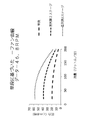
多段直列で構成されたブロワは、その目的が、患者インターフェースにおいて最大30cmH2O(水柱)を提供することによるなど、ユーザの気道を開けるのに十分な圧力を提供することにあるPAP用途に一層好適でありうる。ブロワは典型的には回転運動をもたらすモータを備えており、またモータの最大回転数がモータの設計の一環として予め決定されていることが多い。そこで、所望の空気圧力を達成するために、ブロワの追加段を直列に導入して同じ回転数で空気圧力を増大させるようにしてもよい。図45は46.8kRPMにて回転するブロワの代表的なファン曲線であり、所定の回転数(例えば、モータ)用のブロワから出る空気流の圧力を増大させるために直列に連結された1段以上を備える。図45を見て分かるように、追加段が直列に導入されているので、たとえブロワの回転が増大しなくても空気圧力を増大させることができる。 A blower configured in a multi-stage series is more suitable for PAP applications whose purpose is to provide sufficient pressure to open the user's airway, such as by providing up to 30 cm H2O (water column) at the patient interface. can be preferred. Blowers typically include a motor that provides rotary motion, and the maximum number of revolutions of the motor is often predetermined as part of the motor design. Therefore, in order to achieve the desired air pressure, additional stages of blowers may be introduced in series to increase the air pressure at the same rpm. FIG. 45 is a typical fan curve for a blower rotating at 46.8 kRPM, with one stage connected in series to increase the pressure of the airflow exiting the blower for a given rpm (e.g., motor). Prepare for the above. As can be seen in Figure 45, additional stages are introduced in series so that the air pressure can be increased even if the blower rotation is not increased.
より大きな流量が望ましい用途には、直列ブロワ配置が適さないことがある。例えば、流量がPAPデバイスの典型的な、又は最大予測流量を超える場合、後述されるようにより低い圧力特性の場合にはエアカーテン配置が実装されてもよい。また、マスク及び通気孔(例えば連続通気孔又は可変に構成された通気孔)を備える空気濾過システムはより高い流量を要求することがある。目をさましているユーザの方が、睡眠中のPAPユーザと比べて1回の呼吸量がより多くなるからである。ユーザが適度な運動(例えばウオーキング、バイク乗り、ゴルフ)などの身体活動を行っているならば、ユーザの1回の呼吸量はさらにより多くなりうる。また、作業者はより多い1回の呼吸量を必要としうる、及び作業者は建設現場のような潜在的に汚染された環境の中で作業している場合がある。エアカーテン配置内では提供される圧力は、PAP療法を受けている患者に提供されるものよりも遥かに低い。空気圧を介して人の気道を開ける必要があるPAPデバイスというよりもむしろ、気流(air-current)配置から離れた圧力は、空気侵入を防止するために周囲に対する陽圧において濾過空気を提供することだけを必要とする。 A series blower arrangement may not be suitable for applications where higher flow rates are desired. For example, if the flow rate exceeds the typical or maximum expected flow rate of a PAP device, an air curtain arrangement may be implemented for lower pressure characteristics as described below. Also, air filtration systems with masks and vents (eg, continuous vents or variably configured vents) may require higher flow rates. This is because an awake user will have a higher respiratory volume per breath than a sleeping PAP user. If the user is engaged in physical activity such as moderate exercise (eg, walking, biking, golfing), the user's tidal volume can be even higher. Also, workers may require higher tidal volumes, and workers may be working in potentially polluted environments such as construction sites. The pressure provided within an air curtain arrangement is much lower than that provided to a patient undergoing PAP therapy. Rather than a PAP device that requires opening a person's airway via air pressure, a pressure off air-current arrangement provides filtered air at a positive pressure to the surroundings to prevent air ingress. need only
図46は、所定の回転数(例えば、モータ)用のブロワから出る空気の流れの流量を増大させるために並列に実装された多段ブロワなどの、様々なブロワ実装の代表的なファン曲線である。 FIG. 46 is a representative fan curve for various blower implementations, such as multi-stage blowers mounted in parallel to increase the airflow rate exiting the blower for a given number of revolutions (e.g., motor). .
図46は、所定の流量(例えばグラフにに示されるように50リットル/分)、直列連結されたブロワの追加段の導入は、ブロワ吹出口における圧力をかなり増大させるが、これに対してブロワの追加段が並列に連結されている場合には、ブロワ吹出口における圧力は、ほとんど変化しないままであることを示している。並列に連結されたブロワの追加段の導入は、所定の圧力(例えばグラフに示されるように15cmH2O)についてはブロワ吹出口における流量を増大させる。これに対して直列連結されたブロワの追加段は、ブロワ吹出口における流量に大幅な影響を及ばさない。したがって、並列に連結されたブロワは、圧力増を伴なわずにより大きな流れが提供されるのでエアカーテン配置にとってより有益になりうる。 Figure 46 shows that for a given flow rate (e.g. 50 liters/minute as shown in the graph), the introduction of an additional stage of serially connected blowers significantly increases the pressure at the blower outlet, whereas the blower is connected in parallel, the pressure at the blower outlet remains almost unchanged. The introduction of additional stages of blowers connected in parallel increases the flow rate at the blower outlet for a given pressure (eg 15 cm H2O as shown in the graph). In contrast, an additional stage of blowers connected in series does not significantly affect the flow rate at the blower outlet. Therefore, blowers connected in parallel can be more beneficial for air curtain arrangements as they provide greater flow without increased pressure.
空気濾過用途に適したブロワの一実施例は、並列の複数段を備えかつ図2に示されるように単一軸によって駆動されるブロワでありうる。このようなブロワは第1の端部における第1の吸込口201と、第2の端部における第2の吸込口202、シャフト205とを備えてよい。該シャフト205は、第1のインペラ203と第2のインペラ204に固定結合されてもよい。該第1のインペラ203と第2のインペラ204はシャフト205によって駆動されてもよい。ブロワはまた、増大した圧力において第1の吸込口201と第2の吸込口202によってそれぞれ受信された空気の流れを送出するために第1の及び第2の吹出口(図示せず)を備えてもよい。高流量低圧力の適用内で、スクロール吹出口が使用されてもよい。スクロール吹出口は効率向上をもたらしうる、それによってバッテリをベースにした使用に対しては電力消費量削減を可能にする。また、スクロール吹出口は、小型化が梱包において達成されることを可能にしうる。
One example of a blower suitable for air filtration applications can be a blower with multiple stages in parallel and driven by a single shaft as shown in FIG. Such a blower may comprise a
図3Aは、並列2段を有するブロワ300のアイソメ概略図を示す。該ブロワは2段301及び302及びモータ307をを有してもよい。空気は2つの吸込口303及び304から吸い込まれかつ2つの吹出口305及び306を通って押し出されてもよい。ブロワから出る空気の流れは、幾つかの実装では、1つの流れを形成するように組み合わされてもよい、その代りに、例えばユーザの異なる部位に導かれるように別々のままでもよい。幾つかの形態では、エアカーテン式デバイスは、エアカーテンを提供する吹出口と呼吸のためにユーザに新鮮な空気の流れを提供する吹出口など、多段吹出口を備えてよい。このような形態では、第1の吹出口からの空気の流れがエアカーテンの流れを提供することができ、かつ第2の吹出口からの空気の流れがユーザに新鮮な空気の流れを提供することができる。
FIG. 3A shows an isometric schematic of a
別の実施例では、ブロワは図3Bに示されるように、個別の吹出口から下流にを混合チャンバを備えてよい。該混合チャンバ310は、ブロワ300を収納してもよく、またブロワ・ステージ301及び302から複数の流れを受け取り、かつ複数の流れを結合して1つの空気の流れを形成する。ブロワ・ステージ301及び302に提供された空気は、混合チャンバ内の吸込口311を通って受け取られてもよい。該1つの空気の流れが、吹出口312を通って出力されてもよい。幾つかの形態では、混合チャンバはマフラーとして機能するように構成することによるなど、発生した騒音の量を低減するよう構成されてもよい。該混合チャンバは、1つ以上の音響発泡体、ヘルムホルツ(Helmholtz)チャンバー、及びバッフル、その他を備えてもよい。混合チャンバはトーンノイズ及び/又はブロワによるノイズ出力低減するように構成されてもよい。
In another embodiment, the blower may include a mixing chamber downstream from a separate outlet, as shown in Figure 3B. The mixing
エアカーテンを提供するのに適したモータの別の適した実施例は、図4に示されるような単段ブロワであってもよい。該単段ブロワはモータ405、高さと半径との間の比較的に小さいアスペクト比を有するシングル・インペラベーン402、シャフト403、吸込口401、及び吹出口404を備えてよい。幾つかの実施形態では、インペラは、所定の回転数においてブロワを通って流れつつある空気の大容積流量を送出するために、インペラの半径の一部分より大きな高さを有してもよい。
Another suitable embodiment of a motor suitable for providing an air curtain may be a single stage blower as shown in FIG. The single stage blower may comprise a
前述した通り、マルチプル・ブロワステージを有するモータが使用されてもよい。図5Aと図5Bは、マルチプル・ブロワステージを有するモータを示す。図5Aは、2段ブロワを示し、図5Bは3段モータを示す。このようなブロワは吸込口501、吹出口504、シャフト502及びモータ503を備えた遠心ブロワであってもよい。同様なブロワの実施例が、PCT特許出願第WO2013020167号により詳細に記載されている。このようなブロワは、直列に配置されたブロワステージを含み、また従って、同様に 構成された直列ブロワステージを備える配置と比較して、吹出口において要求される圧力が比較的に高い、用途に適していると思われる。
As previously mentioned, a motor with multiple blower stages may be used. Figures 5A and 5B show a motor with multiple blower stages. FIG. 5A shows a two stage blower and FIG. 5B shows a three stage motor. Such a blower may be a centrifugal blower with
図6に示されるように、軸流ブロワは本出願に適していると思われる。軸流ブロワは遠心ファンと比較して典型的には比較的に低い圧力に対して高い量を発生させることができる。図6に示されるように、軸流ブロワはモータシャフト602に結合されたロータ603と、ロータを取り囲みかつステータベーンを備えるブロワハウジング601とを備える。ブロワは、複数のステージ604を備えてよい、その各々は1つ以上の別個の構成要素上に位置していてもよい、あるいは複数のステータ又はロータステージは単一の構成要素上に位置していてもよい。以下に示されるように、軸方向に分離している。
An axial blower, as shown in FIG. 6, is believed to be suitable for this application. Axial blowers can typically generate high volumes for relatively low pressures compared to centrifugal fans. As shown in FIG. 6, the axial blower comprises a
図7Aは、図6に示される軸流ブロワと互換性のあるロータの一実施例である。多段ロータはモータと結合するための軸方向レセス703を含む単一の、成型された本体703に形成されてもよい。マルチプル・ロータステージは、ロータの単体に一体形成されている。一体形成された単体ロータは製造コストを低減でき、部品数を低減でき、かつ製造公差をも低減し得る。各ステージ702は、互いに軸方向に整列されるようにかつ同じ幾何形状に示されている。図7B及び図7Cは、図7Aのロータによって形成されてもよい軸流ステータ・ステージを示す。ロータ・ステージ704は、軸流ステータ・ステージ形成するようにブロワハウジング705と整列してもよい。幾つかの形態では、ステージは軸方向に整列される必要がないし、また各個別のステージは別のステージとは異なる配置になっていてもよい。
FIG. 7A is an example of a rotor compatible with the axial blower shown in FIG. The multi-stage rotor may be formed in a single, molded
好適なブロワの別の実施例は、図8A及び図8Bに示されるように、遠心ステージ及び軸流ステージの両方を備えるものでもよい。図8A及び図8Bに示されるように、ブロワは第1のステージとして遠心ステージ801を備えてよい。遠心ステージから空気が2つの軸流ステージ802及び803を通ってブロワ内に形成された環状経路に沿って下流に移動しうる。該構成は、ある特定の実施例に適合するように空気流に対して圧力増及び流れ増の組み合わせをもたらしうる。
Another example of a suitable blower may include both centrifugal and axial stages, as shown in Figures 8A and 8B. As shown in Figures 8A and 8B, the blower may comprise a
吸込口に向けて位置決めされた上部に遠心ステージを備える、ロータが図9A~図9Cに示されている。該ロータはインペラブレード903及びインペラ・シュラウド・ディスクを備えてよい。また、ロータは軸流ブレード902がその上に形成されている軸方向に延びる壁901を備えてよい。該軸方向に延びる壁はまた、そこを通って空気の流れが移動する環状流れ経路の一部を形成する。該形態におけるロータはまた、円形キャビティ904を備えてよく、それを介してロータがモータに結合されている。
A rotor is shown in FIGS. 9A-9C with a centrifugal stage on top positioned toward the inlet. The rotor may comprise
図10A及び図10Bは、内壁付き外部ハウジング1001の第1の半分を示す。ステータベーン1002は、内壁上に形成されてもよい。該外部ハウジング1001は、ブロワの遠心ステージ及び軸流ステージ用のステータベーン1002が両方とも直線壁上に形成されるように構成されている。このような構造はハウジングの製造可能性を改善しうる。外部ハウジング1001の2つの半分割の各々が互いに係合するように構成されたキー及び相補レセスを備えてよい。複数の部分における外部ハウジング1001の構造は、各部分がステータ・ベーン1002と一体成型されかつ内壁から内側へ突出することを可能にする。
10A and 10B show the first half of the inner walled
モータはモータハウスとともに収納されてもよい。図11A及び図11Bは、モータハウジングの一例を示す。該モータハウジングは、シャフトがそこから突出することができるキャビティ1101を含んでよい。また、モータハウジングは空気の流れのための一組の吹出口キャビティ1104を含んでよい。モータハウジングはまた、モータハウジングをモータに接続するための接続点1102及び1103を含んでもよい。
The motor may be housed with the motor house. 11A and 11B show an example of a motor housing. The motor housing may include a
エアカーテンシステムに使用されてよいモータの別の実施例は、テスラブロワであってもよい。テスラブロワは、ブロワにスリムプロファイルをもたらしうる薄い平坦なディスクを有してもよい。したがって、ブロワは容易に隠すことができかつ目立たないようにすることができる。テスラ(Tesla)ブロワはブレード無しであるので、テスラブロワはトーンノイズ出力を発生させないで作動することができる。 Another example of a motor that may be used in the air curtain system may be a Tesla blower. A Tesla blower may have a thin flat disk that can give the blower a slim profile. Therefore, the blower can be easily hidden and discreet. Because the Tesla blower is bladeless, it can operate without generating a tonal noise output.
4.2.2.1 本技術のためのモータ-ブロワ
上記のブロワの1つ以上は、エアカーテンデバイス、患者インターフェースを備えた空気濾過デバイス若しくはエンタテインメント・エアシステムなどの本技術の実施例に使用するのに適したものとしてもよい。
4.2.2.1 Motor-Blowers for the Technology One or more of the above blowers are used in embodiments of the technology such as air curtain devices, air filtration devices with patient interfaces or entertainment air systems. may be suitable for
適切なブロワの設計及び選定は、システムの意図された使用及び形状又はサイズに応じて変えてもよい。ブロワは出力流れ及び/又は圧力を変化させるためにサイズの増大又は縮小をしてもよい。しかしながら、適切なブロワ構成の設計は、そのユーザに対して目障りであることを最も少なく提示しかつ電力消費量を最小限に抑えることによってその動作時間を最大化するであろう本技術用のブロワの設計を可能にするであろう。例えば、直列で多過ぎるステージを有するブロワは、結果的に実用に供するブロワとしては大き過ぎるものになりうる。 Appropriate blower design and selection may vary depending on the intended use and shape or size of the system. Blowers may increase or decrease in size to vary output flow and/or pressure. However, the design of an appropriate blower configuration will present the least obtrusiveness to its users and maximize its operating time by minimizing power consumption. would allow the design of For example, a blower with too many stages in series can result in a blower that is too large for practical use.
ブロワがユーザへの空気の流れの送出点より近位に、例えばユーザの肩の上に、位置していてかつ空気送出導管が比較的に大径、例えば19mm内径であれば、低い圧力において所望される流量を提供することができるブロワは十分でありうる。このようなブロワは単段遠心ブロワ又は多段軸流ブロワであってよい。しかしながら、より高い流量が所望されるならば、遠心ブロワを並列に連結された複数のブロワステージを備えてよい。 If the blower is located proximal to the delivery point of the airflow to the user, e.g., on the user's shoulder, and the air delivery conduit is of relatively large diameter, e.g. A blower that can provide the desired flow rate may be sufficient. Such blowers may be single-stage centrifugal blowers or multi-stage axial blowers. However, if higher flow rates are desired, centrifugal blowers may be provided with multiple blower stages connected in parallel.
別の実施例では、ブロワはユーザへの空気の流れの送出点より遠位に、例えばユーザの腰の上に位置していてもよい。ブロワが狭いチューブによってユーザ・フロー・インターフェースに連結されているならば、ブロワは高い圧力を提供できることを必要とする。したがって、ハイブリッド軸流及び遠心ブロワが適切であるとされてもよい。 In another embodiment, the blower may be located distal to the point of air flow delivery to the user, eg, on the user's waist. If the blower is connected to the user flow interface by a narrow tube, the blower needs to be able to provide high pressure. Therefore, hybrid axial and centrifugal blowers may be suitable.
4.2.3 エアカーテン
エアカーテンは、周囲環境を、内部環境と外部環境の、2つの別個の環境に分割するために発生されてもよい。内部環境はエアカーテンシステム(例えば、ユーザ・フロー・インターフェース)から到来する空気を実質的に含有するのに対して、外部環境はエアカーテンシステムを通って行かなかった空気を含有する。周囲空気圧に対して、陽空気圧、又は等価空気圧は、エアカーテン「エンクロージャ」の外部から空気の侵入を防止するためにエアカーテンによって維持される内部環境内に維持されてもよい。
4.2.3 Air Curtain An air curtain may be generated to divide the ambient environment into two separate environments, an internal environment and an external environment. The internal environment substantially contains air coming from the air curtain system (eg, the user flow interface), while the external environment contains air that did not pass through the air curtain system. Relative to ambient air pressure, positive air pressure, or equivalent air pressure, may be maintained within the internal environment maintained by the air curtain to prevent air intrusion from outside the air curtain "enclosure."
「エアカーテンシステム」の概略図は図12に示されている。概略図においてブロワ1202は空気ダクト1201の近くに位置している。該ブロワ1202は圧力低下を最小化しかつバッテリ寿命を最大化するために空気ダクト1201の近くに位置している。例えば、空気圧力は、空気流れがフィルタ1204、導管、及び空気ダクト1201を通って移動するので、ブロワの吹出口と及びユーザの顔との間でかなり低下する可能性がある。ブロワの吹出口とユーザの顔との間の圧力差は、空気圧経路の幾何形状(例えば横断面形状及び面積、経路の長さ)、使用されるフィルタの形式、及び使用されるフィルタの寸法を含むが、それらに限定されない複数の他のパラメータに応じてさらに変わりうる。ブロワ1202及びフィルタ1204は、流れ発生器の一部であってもよい。
A schematic diagram of the "air curtain system" is shown in FIG. In the schematic drawing,
図12のシステムにおいて、空気ダクト1201は、例えば、長さ25cm及び直径19mmであってよい、またブロワ1202はノイズ・エンクロージャ1203内に懸垂されていて、大きな吸込口フィルタ1204をが有している。図12のシステムは、例えば150リットル/分の一定の流れ及び例えば12cmH2Oのブロワ両端の圧力を有してもよい。推定電力消費量は13Wであってもよい。フィルタ1204、導管、及び空気ダクト1201は、圧力損失の原因になりうる。実施例エアカーテンシステムにおいて、空気ダクト1201は恐らく、例えば、0.25cmH2Oの圧力損失を有する可能性があり、またフィルタ1204は4cmH20の圧力損失を有する可能性がある。また、各空気送出導管は0.1cmH2Oの圧力損失を蒙りうる。したがって、1Wの静止電力を想定すると、6セルバッテリ(12Whセル容量)は初期状態で4.8時間もたせることができるであろう。提供される個数が代表的でありかつ同じ技術を用いた他の個数及び範囲が可能であることに留意されたい。
In the system of FIG. 12, air duct 1201 may be, for example, 25 cm long and 19 mm in diameter, and
適正な流れ角は、エアカーテンシステムから空気を提供するに際してより高い効率を発揮しうる。空気の流量は、エアカーテンシステムのユーザによって吸い込まれる空気の割合を増加させることに関しては流れ角に比べて余り影響を及ぼさない。図31に目を参照すると、0%~90%の範囲に及び、ユーザによって吸い込まれるエアカーテンシステムによって提供される空気の割合を示すシミュレーションの結果が、Y軸上に提示されている。シミュレーション中に読取り値が様々な角度、距離、及び流量において取られた。図31に示されるように、Qinletとラベルされた、150リットル/分(秒当たり2.5メートル)及び300リットル/分(秒当たり5メートル)における2つの流量が使用された。2つの流量の各々が、空気ダクトなどのユーザ・フロー・インターフェースとユーザの鼻孔との間で測定された3つの異なる距離(mm単位)において適用された。これらの距離は図31内にAnteriorOffset(前方オフセット)とラベルされている。各距離について、鼻孔に対するユーザ・フロー・インターフェースの吹出口の流れ角の範囲が度単位で測定されかつ流れ角(α)とラベルされてX軸上に示されている。シミュレーションのすべての測定値が、周囲空気速度は無しで摂氏25度の周囲空気温度において取られた。図32は、どのように前方オフセット距離(AnteriorOffset)と流れ角(α)が測定されたかのサジタルビューを示している。 A proper flow angle can result in greater efficiency in providing air from the air curtain system. Air flow rate has less effect than flow angle on increasing the percentage of air ingested by the user of the air curtain system. Referring to FIG. 31, simulation results are presented on the Y-axis showing the percentage of air provided by the air curtain system inhaled by the user, ranging from 0% to 90%. Readings were taken at various angles, distances and flow rates during the simulation. Two flow rates were used, labeled Qinlet, at 150 liters/minute (2.5 meters per second) and 300 liters/minute (5 meters per second), as shown in FIG. Each of the two flow rates was applied at three different distances (in mm) measured between a user flow interface, such as an air duct, and the user's nares. These distances are labeled LaterOffset in FIG. For each distance, the range of flow angles of the outlets of the user flow interface relative to the nostrils is measured in degrees and shown on the X-axis labeled flow angle (α). All measurements in the simulation were taken at an ambient air temperature of 25 degrees Celsius with no ambient air velocity. FIG. 32 shows a sagittal view of how the anterior offset distance (AnteriorOffset) and flow angle (α) were measured.
図31の散布図を見ても分かるように、ユーザによって吸い込まれる清浄化空気の割合に関する意義の優先度は角度(流れ角)、距離(AnteriorOffset)、次いで流量(Qinlet)である。流れが約40度の流れ角を付けてユーザの気道に向けて導かれるので、ユーザによって吸い込まれる清浄化空気の割合は大抵のシミュレーションにおいて60%より高い。 As can be seen from the scatter plot of FIG. 31, the priority of significance for the fraction of clean air inhaled by the user is angle (flow angle), distance (AnteriorOffset), then flow rate (Qinlet). Because the flow is directed toward the user's airway with a flow angle of about 40 degrees, the percentage of cleansed air inhaled by the user is higher than 60% in most simulations.
50mmの前方オフセットの場合のエアカーテンシステムからの空気の供給が、図33に示されている。流れ角が17度でありかつ流量が2.5メートル/秒である。図33を見ても分かるように、エアカーテンシステムから供給される空気は、ユーザの鼻孔において約50%である。図34において、75mmの前方オフセットを有するエアカーテンシステムが示されている。流れ角が30度であり流量が2.5メートル/秒である。図34を見ても分かるように、ユーザの鼻孔におけるエアカーテンシステムから供給される空気は約75%である。図34において設けられたより高い流れ角は、エアカーテンシステムからより高い割合の清浄化空気をユーザに供給する。 The air supply from the air curtain system for a forward offset of 50 mm is shown in FIG. The flow angle is 17 degrees and the flow rate is 2.5 meters/second. As can be seen in Figure 33, the air supplied from the air curtain system is approximately 50% at the user's nostrils. In FIG. 34 an air curtain system with a forward offset of 75 mm is shown. The flow angle is 30 degrees and the flow rate is 2.5 meters/sec. As can be seen in Figure 34, the air supplied by the air curtain system at the user's nostrils is about 75%. The higher flow angle provided in FIG. 34 provides the user with a higher percentage of purified air from the air curtain system.
4.3 スマート空気清浄化技術
エアカーテンシステムは、清浄空気システム(CAS)を作成するために使用されことができる。該CASは、濾過された空気をユーザに提供する前に空気から微粒子やガスを除去するために多段フィルタを備えてよい。CASはまた、周囲空気から揮発性ガスとともに臭い、バクテリア、及びウイルスを除去する能力を有してもよい。空気を濾過した後、CASは次いでユーザ・フロー・インターフェース104を通ってユーザに濾過された空気を提供してもよい。提供される空気は、少なくとも1つのエアカーテンの形態でよい。幾つかの実施例では、CASはすべてのデータをディスプレイ上に通信してもよい。CASは直接ハウジング上に制御機能を有してもよい。他の実施例では、CASはすべてのデータをスマートフォン又はコンピュータプログラムへ通信してもよくかつオンライン・データベースを介して該データを提示してもよい。CASはまた、スマートフォン、タブレット、コンピュータ、その他に表示されたグラフィカル・ユーザインターフェース(GUI)によって制御されてもよい。
4.3 Smart Air Cleaning Technology Air curtain systems can be used to create Clean Air Systems (CAS). The CAS may include a multi-stage filter to remove particulates and gases from the air prior to providing the filtered air to the user. CAS may also have the ability to remove odors, bacteria, and viruses along with volatile gases from ambient air. After filtering the air, the CAS may then provide the filtered air to the user through the
図1に示されるように、能動型清浄空気システムは流れ発生器1603、スマート・クリーンエア・フィルタリング103、及びユーザ・フロー・インターフェース104を含んでよい。該流れ発生器は、前述した任意のモータであってもよい、またフィルタとセンサを含むことができる。CASの実施例実装が図14に示されている。汚れた空気1401は最初にプレフィルタ1402を通過されることによって流れ発生器内へ引き込まれてもよい。該プレフィルタ1402は、モータ1403を損傷させる恐れもある周囲空気から粒子を除去する。該モータ1403は、図14に示されるように、次いで一次フィルタ1404を通って空気を押し込んでもよい。該一次フィルタ1404は、周囲空気から望まれていない微粒子及び/又は揮発物質を除去してもよい。濾過された空気は、次いで清浄化空気1405としてユーザ・フロー・インターフェース104を通ってユーザへ出力されてもよい。
As shown in FIG. 1, an active clean air system may include a
CASは図35に示されるように、流れ発生器1603の動作を制御するためにコントローラ3501をさらに備えてもよい。該コントローラ3501は、例えば流れ発生器の流量を調節するとともに流れ発生器によって発生された空気圧力を調節するために使用されてもよい。コントローラ3501は、CASと同じハウジング内に収納されてもよい。ユーザ・フロー・インターフェース3504は、コントローラ3501を収納しているCASと直接結合されてもよい。汚れた空気3503は、次いでコントローラ3501を収納しているCASを介して濾過されてもよい、また清浄化空気が次いでユーザ・フロー・インターフェース3504へ送達されてもよい。コントローラ3501は、ユーザに流量、流れ圧力、流れ温度、及び流れ湿度などのCASの状況を調節させることを許容するためにタッチ画面を含んでよい。その代りに、コントローラ3501は、スマートフォン、タブレット、コンピュータ、スタンドアロンデバイスなどであってもよい、コントローラデバイス3502によって作動されてもよい。該コントローラデバイス3502は、ユーザにコントローラ3501を遠隔制御させることを許容するためにコントローラ3501と無線通信してもよい。
The CAS may further comprise a
幾つかの実施形態では、CASはブロワ又はコントローラを必要せずに受動的に動作するように構成されてもよい。例えば、図36Aに示されるように、CASはカートリッジホルダー3690、送出導管3670及びフロー・インターフェース3680を含む送出システムから構成されてもよい。該カートリッジホルダーは、図36Bに示されるように、カートリッジ3620を保持してもよい。該カートリッジ3620は、軽量でありかつ高い内圧に耐える能力を有する、金属又はプラスティックを含む1種以上の材料から構成されてもよい。カートリッジ3620は清浄、圧縮空気で充填されてもよく、送出導管3670を通ってユーザインターフェース3680まで空気を放出しうる。
In some embodiments, the CAS may be configured to operate passively without the need for a blower or controller. For example, as shown in FIG. 36A, a CAS may consist of a delivery system including
送出システム(図示せず)上の調整弁は、送出導管3670を通ってユーザインターフェース3680までの圧縮空気の流量を制御しうる。このような送出システムは、ブロワもコントローラも必要としなくてよいので小型、軽量、及び動作が静かでありうる。幾つかの実施形態では、ユーザによって要求される場合、増加気流を提供することによって能動型CASを補足するために受動型カートリッジ送出システムが使用されてもよい。また、受動型CASはまた、能動型CASに対するバックアップとして使用されてよい。この点に関しては弁調節器は能動型CASがもしも作動不能になった場合に自動又は手動で開放されてもよい。
A regulating valve on the delivery system (not shown) may control the flow of compressed air through
カートリッジ3620は再充填清浄器ベース3610によって圧縮、清浄空気が充填されてもよい。この点に関しては、再充填清浄器ベース3610は空気を濾過し、圧縮し、及びオプションとして湿らし及び/又は香りを漂わせることができる。カートリッジ3620は再充填清浄器ベース3610内に、充填口3630の中に設置されてもよい。該充填口3630は、カートリッジ3620上で、スプリングバルブなどの、弁3625を開いてもよい。再充填清浄器ベース3610は、次いで濾過され、圧縮され、及びオプションとして加湿された空気を開いた弁3625を通ってカートリッジ3620の中に注入しうる。充填口3630からカートリッジ3620を取り外し次第、弁3625は封止してもよい。カートリッジ3620は、1時間、若しくは、多かれ少なかれ、再充填する必要があるまで、作動するのに十分な圧縮空気を格納しうる。
再充填清浄器ベース3610は、インペラブロワを使用して空気を圧縮してもよい。この点に関しては、インペラブロワは空気を通口3640に吸い込んでもよい。通口3640は空気がインペラブロワを通過する前に空気から大きな粒子を濾過するためにイニシアルフィルタを含んでよい。インペラブロワは、次いで空気を充填キャニスタ3620の中に押し込んでもよく、またより多くの空気が充填キャニスタの中へ押し込まれるのでその空気を圧縮する。幾つかの実施形態では、ストラップ3650及びクリップ3660は、携携帯性のためにべースがユーザ又は他の物体にしっかりと固定されることを可能にするために再充填清浄器ベースに取り付けられてもよい。この点に関しては、再充填清浄器ベースはバッテリ又は有線電源を介して電力供給されてもよい。
The
幾つかの実施形態では、インペラブロワは水などの液体を蒸発させうる、1つ以上の加熱要素を通り越して空気を押し込んでもよい、それによって湿度を空気に加える。他の実施形態では、湿度はまた再充填清浄器ベース3610内で別個の水ウイックカートリッジを介してシステムへ導入されることができる。
In some embodiments, the impeller blower may force air past one or more heating elements that may vaporize liquids such as water, thereby adding humidity to the air. In other embodiments, humidity can also be introduced into the system via a separate water wick cartridge within the
幾つかの実施形態では、送出システムはデバイス内に生じうる任意のバクテリア及び/又は臭いを低減するために抗微生物材料ライニング及び/又は抗微生物小袋を含んでよい。このような抗微生物材料は、バクテリア及び臭いを吸収するために銀の糸、メリノ羊毛、又は竹炭を含んでよい。このような材料ライニング及び/又は小袋は取り外し可能、交換可能な、及び/又は洗濯可能としてもよい。エアカーテンシステムは携帯又は装着されてもよいように持ち運び可能及びコンパクトとして設計されうる。例えば、コンパクトブロワは、図37Aに示されるように、気流を発生させるためのインペラ3720、空気を患者インターフェースに送達するための導管730、及びコントローラ、バッテリ、及び/又はセンサが位置決めされてよいアタッチメント空間3740を含んでよい。加えて、コンパクトブロワ3710はまた、インペラ3720によって吸い込まれた空中浮遊粒子を除去するために吸気フィルタ3770を含んでよい。コンパクトブロワはストラップ3760とともにユーザ又は他の物体に取り付けられてもよい。
In some embodiments, the delivery system may include an antimicrobial material lining and/or an antimicrobial pouch to reduce any bacteria and/or odor that may develop within the device. Such antimicrobial materials may include silver threads, merino wool, or bamboo charcoal to absorb bacteria and odors. Such material linings and/or pouches may be removable, replaceable and/or washable. The air curtain system can be designed to be portable and compact so that it may be carried or worn. For example, a compact blower, as shown in FIG. 37A, includes an
図37Bを参照すると、コンパクトブロワ3710はストラップ3760を用いてユーザの体3790に取り付けられるように構成されてもよい。幾つかの実施形態では、コンパクトブロワ3710の幅は10mm未満、若しくは多かれ少なかれ、それをポケット3795内に置ける程度であってよい。ポケット3795内に置かれている状態でコンパクトブロワ内に空気を吸い込むことができるようにエキステンダーが取り付けられてもよい。図37Bにおけるコンパクトブロワ3710を保持するポケット3795の引き延ばした図示を参照すると、フィルタ・エキステンダー3775が吸気フィルタ3770に取り付けられてもよい。そういうものとして、吸気フィルタ3770は空気をエキステンダー3775を通ってコンパクトブロワ内に吸い込んでもよい。エキステンダー3775はポケットの外側とちょうど内側の境のところに位置している。幾つかの実施形態では、コンパクトブロワは、導管3730によって導入される流れの障害を低減するとともにユーザが頭を動かすときの抵抗を低減するためにユーザの頭の近くに置かれてもよい。
Referring to FIG. 37B,
エアカーテンシステムが持ち運び可能であってよいので、バッテリ電源によって電力供給されてもよい。また、ユニットは、ユーザが医療器具を使用しているようには見えないように、視界から隠れるか若しくはカモフラージュできるようにすべきである。幾つかの実施形態では、エアカーテンシステムは、電力使用量を最小限に抑えるためにユーザが吸い込んでいる間だけエアカーテンを提供してもよい。 Since the air curtain system may be portable, it may be powered by a battery power source. Also, the unit should be able to be hidden from view or camouflaged so that it does not appear that the user is using a medical device. In some embodiments, the air curtain system may provide the air curtain only while the user is inhaling to minimize power usage.
空気を清浄化するのに利用されるフィルタは、CASの中に容易に設置できかつCASから取り外しできるカートリッジの形態で提供されてもよい。異なるフィルタはユーザのニーズに応じて異なる方式の濾過を提供してもよい。例えば、臭い除去を提供するフィルタもあれば、一方ではバクテリア除去を提供するカートリッジもある。幾つかの実施例では、濾過効果及び/又は効率を向上させるために多段フィルタ103が利用されてもよい。各フィルタが異なる種類の汚染物質の濾過を提供するので、マルチタイプのフィルタが同時に利用されてもよい。幾つかの実施形態では、CASはユーザの環境の中に存在する微粒子及び/又は揮発物質に基づいて特定のフィルタを介して空気の流れを自動的に制御するために自己構成可能であってもよい。フィルタは必要とされない若しくはもはや正常に機能しない場合に容易に交換されてもよい。幾つかの実施形態では、気流に対して全く無いか若しくは極めて少ない障害しかもたらさない無制限フィルタが使用されてもよい。 Filters utilized to purify the air may be provided in the form of cartridges that can be easily installed into and removed from the CAS. Different filters may provide different types of filtering depending on the user's needs. For example, some filters provide odor removal while other cartridges provide bacteria removal. In some embodiments, multi-stage filters 103 may be utilized to improve filtering effectiveness and/or efficiency. Multiple types of filters may be utilized simultaneously as each filter provides filtration of a different type of contaminant. In some embodiments, the CAS may be self-configurable to automatically control airflow through specific filters based on particulates and/or volatiles present in the user's environment. good. Filters may be easily replaced when not needed or no longer functioning properly. In some embodiments, a limitless filter may be used that poses no or very little obstruction to the airflow.
一実施例フィルタ方式が高効率微粒子エアフィルタ(HEPA Filter)である。米国政府規格によってHEPAとして資格を得るためには、エアフィルタはHEPAフィルタを通過する空気から0.3μm粒子の99.97%を除去しなければならない。HEPAフィルタは空気がフィルタを通過するにつれて空気中の粒子を遮断することによって機能する。空気がHEPAフィルタを通過するにつれて、空気中の粒子は繊維に衝突させられて空気から除去される。 One example filter system is a high efficiency particulate air filter (HEPA Filter). To qualify as HEPA per US government standards, an air filter must remove 99.97% of 0.3 μm particles from air that passes through the HEPA filter. HEPA filters work by blocking particles in the air as it passes through the filter. As the air passes through the HEPA filter, particles in the air are struck by the fibers and removed from the air.
CASにおいて利用することができるフィルタの別の実施例は分極媒体エレクトレットフィルタである。大抵の分極媒体電子エアクリーナは、分極電界を確立するために24ボルト電流を安全なDC電圧に変換する。空気中の粒子が電界を通過するにつれて、粒子は分極されてくる。該分極された粒子は使い捨て繊維媒体パッドに付着する。 Another example of a filter that can be utilized in CAS is a polarized media electret filter. Most polarized media electronic air cleaners convert 24 volt current to a safe DC voltage to establish a polarized electric field. As particles in air pass through an electric field, they become polarized. The polarized particles adhere to the disposable fibrous media pad.
イオナイザー清浄器は、CAS内で使用されることができる別の方式のフィルタである。イオナイザー清浄器の使用は、帯電空気又はガスイオンを発生するために電気表面又は針を帯電させた。これらのイオンは、次いで空気がイオナイザー清浄器を通過するにつれて空気中の粒子に取り付く。粒子がイオナイザー清浄器を通過し続けるにつれて、粒子は帯電集塵板に吸着される。 An ionizer purifier is another type of filter that can be used in CAS. The use of ionizer purifiers charged an electrical surface or needle to generate charged air or gas ions. These ions then attach to particles in the air as it passes through the ionizer purifier. As the particles continue to pass through the ionizer purifier, they are attracted to the charged collecting plate.
熱力学殺菌フィルタがまた使用されてもよい。該技術は空気を200℃(392°F)前後まで加熱することができる。空気が加熱されるにつれて、バクテリア、ウイルス、イエダニ・アレルゲン、糸状菌及び真菌胞子などの粒子が焼却される。もしかすると最高99.9%の微生物粒子を熱力学殺菌フィルタを使用して除去することができる。 A thermodynamic sterilizing filter may also be used. The technology can heat air to around 200°C (392°F). As the air is heated, particles such as bacteria, viruses, dust mite allergens, mold and fungal spores are incinerated. Possibly up to 99.9% of microbial particles can be removed using a thermodynamic germicidal filter.
能動型炭素フィルタがまたCASにおいて使用されてよい。能動型炭素は分子ベースで揮発性薬品を吸収することができる多孔質材料である。能動型炭素フィルタは空気からオイルベーパ、臭い、及び他の揮発性有機化合物を除去するために圧縮空気及びガス浄化に通常使用される。 Active carbon filters may also be used in CAS. Active carbon is a porous material that can absorb volatile chemicals on a molecular basis. Active carbon filters are commonly used in compressed air and gas purification to remove oil vapors, odors, and other volatile organic compounds from the air.
静電フィルタはまたCASにおいて使用されてもよい。該静電フィルタは材料の多層をサンドイッチ状に一括はさむことによって機能しうる。空気は次いでこれらの層を通過させてもよい。空気が材料の層を通過するにつれて、空気中の粒子が粒子とフィルタ層との間の摩擦の結果として帯電されうる。該帯電した粒子は、次いで該帯電粒子とは反対荷電のものであるフィルタ内の他の層に付着されてよい。 Electrostatic filters may also be used in CAS. The electrostatic filter may work by sandwiching multiple layers of material together. Air may then pass through these layers. As air passes through the layer of material, particles in the air can become charged as a result of friction between the particles and the filter layer. The charged particles may then adhere to another layer within the filter that is of opposite charge to the charged particles.
写真触媒酸化フィルタシステムはまた、CASにおいて使用するのが可能である。写真触媒酸化フィルタシステムは有機汚染物質を完全に酸化及び劣化することができる。例えば、数百PPM(百万分率)以下などの低濃度の揮発性有機化合物が完全に酸化される見込みが最も高い。写真触媒酸化フィルタシステムは触媒(通常二酸化チタン(TiO2))を能動化させかつバクテリア及びウイルス酸化させるために短波紫外線を使用する。 A photocatalytic oxidation filter system can also be used in CAS. Photocatalytic oxidation filter systems are capable of fully oxidizing and degrading organic contaminants. For example, low concentrations of volatile organic compounds, such as a few hundred parts per million (PPM) or less, are most likely to be completely oxidized. Photocatalytic oxidation filter systems use short wave ultraviolet light to activate a catalyst (usually titanium dioxide (TiO2)) and oxidize bacteria and viruses.
表3は、以下に、フィルタ形式及びそれらのフィルタが効果的に除去しうる汚染物質の種類の概要を紹介する。 Table 3 below provides an overview of filter types and the types of contaminants they can effectively remove.

清浄空気システム(CAS)はまた、システム、周囲の環境、及びユーザを監視するためにセンサ及び無線通信装置を収納する。無線通信装置はGPS、Bluetooth、Wi-Fi、セルラーデータネットワークなどの形態にすることができる。センサ及び無線通信装置を介して得られた情報を利用することによって、CASは受信されたデータに基づいて事後対応の保護をもたらすことが可能になる。CASはまたユーザの健康及び環境を監視してもよい。 A clean air system (CAS) also houses sensors and wireless communication devices to monitor the system, the surrounding environment, and the user. Wireless communication devices can be in the form of GPS, Bluetooth, Wi-Fi, cellular data networks, and the like. By utilizing information obtained via sensors and wireless communication devices, CAS can provide reactive protection based on the data received. CAS may also monitor the user's health and environment.
対処型保護は、清浄空気システム(CAS)によって提供されてもよい。例えば、CASは表3に掲げているものなどの汚染物質に関してリアルタイム連続的に監視してもよい。汚染物質が存在しているとCASが判定した場合、システムはユーザに連絡することができる。CASはまた、ユーザに対して警告を発するためにセンサから受信された情報を使用してもよい。このような警告はCAS上に実装されているスマート汚染警告システムによって発生されてもよい。該スマート汚染警告システムは、可視又は可聴方式でデバイス上のセンサの現在又は履歴的読取り値を投影又は表示するためにPM2.5センサなどの汚染センサからの読取り値を使用してもよい。そういうものとして、ユーザとともに、その近くに居合わせた他の人々はそれらの環境における汚染レベルを知らされてもよい。別の実施例では、CASはユーザの現在位置の空気温度及び汚染物質含有量が呼吸器疾患などの健康状態を引き起こす可能性がありうることを指摘するために警告をトリガーしてもよい。また、該システムは検出された汚染物質のより効果的な濾過のために濾過強さを向上させる又はフィルタカートリッジを交換するようにユーザに警告してもよい。 Reactive protection may be provided by clean air systems (CAS). For example, CAS may continuously monitor in real time for contaminants such as those listed in Table 3. If the CAS determines that contaminants are present, the system can contact the user. CAS may also use information received from sensors to issue alerts to users. Such warnings may be generated by a smart pollution warning system implemented on the CAS. The smart pollution warning system may use readings from pollution sensors, such as PM2.5 sensors, to project or display current or historical readings of sensors on the device in a visible or audible manner. As such, the user, as well as other people in the vicinity, may be informed of pollution levels in their environment. In another example, the CAS may trigger an alert to indicate that the air temperature and pollutant content at the user's current location can potentially cause a health condition such as respiratory illness. The system may also alert the user to increase the filtration strength or replace the filter cartridge for more effective filtration of detected contaminants.
その代りに、CASはセンサ読取り値に基づいて濾過を自動的に調節してもよい。清浄空気システムは、フィードバック・ループにおいてコントローラと結合された1つ以上の空気質センサを実装してもよい。コントローラは1つ以上の空気質センサからの信号に応答して1つ以上のフィルタの動作を設定するように構成されることができる。例えば、空気質センサが多量の花粉を感知するならば、コントローラは花粉を除去するのにどの方式のフィルタが効果的であるかを判定することができる。HEPAフィルタが花粉を除去するのに効果的であるので、コントローラはCASにHEPAフィルタを介して空気の濾過を開始させることができる。その代りに、コントローラは花粉カウントが高いこと及びHEPAフィルタが使用されるべきであることをユーザに通知することもできる。CASはまた、ユーザが汚染された区域にかなり長時間いたこと及びよりクリーンで、汚染されていない区域を探すべきことをユーザに警告することもできる。 Alternatively, the CAS may automatically adjust filtration based on sensor readings. A clean air system may implement one or more air quality sensors coupled with a controller in a feedback loop. The controller can be configured to set the operation of the one or more filters in response to signals from the one or more air quality sensors. For example, if the air quality sensor senses a large amount of pollen, the controller can determine which type of filter is effective in removing the pollen. Since HEPA filters are effective in removing pollen, the controller can cause the CAS to begin filtering air through the HEPA filters. Alternatively, the controller could notify the user that the pollen count is high and that a HEPA filter should be used. CAS can also warn the user that he or she has been in a contaminated area for too long and should seek out a cleaner, uncontaminated area.
コントローラはまた、オンライン・データベース及び情報にアクセスするためにGPSセンサ及び無線通信装置(例えばWi-Fiアンテナ及びモジュール)などの位置センサとともに構成されてもよい。例えば、コントローラは、GPSを使用してユーザの位置を検出してもよい。位置データに基づいてコントローラ無線通信装置を利用して区域における既知の汚染物質のデータベースにアクセスしもよい。コントローラが区域における位置及び汚染物質を判定した後、コントローラは供給された空気から当該汚染物質を除去するためにCASの1つ以上のフィルタの動作を設定することができる。あるいはまた、コントローラは1つ以上のフィルタの動作を設定しないで、その代わりにユーザに1つ以上のフィルタの動作を設定するように知らせてもよい。 The controller may also be configured with location sensors such as GPS sensors and wireless communication devices (eg, Wi-Fi antennas and modules) to access online databases and information. For example, the controller may use GPS to detect the user's location. A database of known contaminants in the area may be accessed using the controller wireless communication device based on the location data. After the controller determines the location and contaminants in the area, the controller can set the operation of one or more filters of the CAS to remove the contaminants from the supplied air. Alternatively, the controller may not set the behavior of one or more filters and instead inform the user to set the behavior of one or more filters.
コントローラはまた、無線通信装置を使用してデイリー及び地域気象及び空気質予測にアクセスしてもよい。受信された気象及び/又は空気質データに基づいて、コントローラはユーザがいかなる有害粒子をも吸い込まないようにするために1つ以上のフィルタの動作を設定してもよい。また、コントローラは濾過のための強さレベルを設定してもよい。あるいはまた、コントローラは1つ以上のフィルタの強さ又は動作設定しないで、その代りに1つ以上のフィルタの動作又は強さを設定するようにユーザに知らせてもよい。受信された気象及び/又は空気質データはユーザが位置を変更するときに更新されてもよい。 The controller may also access daily and regional weather and air quality forecasts using wireless communication devices. Based on the received weather and/or air quality data, the controller may set the operation of one or more filters to prevent the user from inhaling any harmful particles. The controller may also set the strength level for filtering. Alternatively, the controller may not set the strength or operation of one or more filters, instead informing the user to set the operation or strength of one or more filters. The received weather and/or air quality data may be updated when the user changes location.
ユーザの健康及び環境モニタリングはまた、清浄空気システムによって行われてもよい。例えば、コントローラはユーザの生理的なデータを検出するように構成された1つ以上のユーザセンサと結合されてもよい。このようなデータは心拍数データ、発汗データ、温度データ、ブレス流量データ、O2飽和データなどであってもよい。センサは心拍数センサ、湿度センサ、サーミスタ、流れセンサ、酸素濃度計、その他の任意の1つ以上であってもよい。センサからの生理的なデータが記録されてユーザへ戻されてもよい。ユーザへの通信はCAS上で行われてもよいし若しくはコンピュータ又はスマートフォン上のオンラインデータベースを介してアクセスされてもよい。加えて、生理的なデータはユーザのプロファイルを備えているオンラインデータベースへ通信されてもよい。それに応じてユーザはデータベースにアクセスしてもよいしまたプロファイル中の情報をレビューしてもよい。また、フィードバック信号は、ユーザが眠り込んたり若しくは目を覚ましたりする場合にそれぞれCASのスイッチを入れたり切ったりするために使用されることができる。幾つかの実施形態では、CASは常にスイッチオンである。幾つかの実施形態では、生理的なデータはユーザの病気を判定するために分析されてもよい。例えば、ユーザが眠っている間に取り込まれたユーザデータは睡眠障害呼吸を判定するために分析されてもよい。 User health and environmental monitoring may also be provided by the clean air system. For example, the controller may be coupled with one or more user sensors configured to detect physiological data of the user. Such data may be heart rate data, perspiration data, temperature data, breath flow data, O2 saturation data, and the like. The sensors may be heart rate sensors, humidity sensors, thermistors, flow sensors, oximeters, and/or any other. Physiological data from the sensors may be recorded and returned to the user. Communication to the user may be on the CAS or accessed via an online database on a computer or smart phone. Additionally, physiological data may be communicated to an online database containing user profiles. In response, the user may access the database and review the information in the profile. Feedback signals can also be used to switch the CAS on and off when the user falls asleep or wakes up, respectively. In some embodiments, CAS is always switched on. In some embodiments, physiological data may be analyzed to determine the user's illness. For example, user data captured while the user is asleep may be analyzed to determine sleep disordered breathing.
CASはまた、視標追跡センサを含んでもよい。該視標追跡センサ及び対応するアルゴリズムはユーザが何に目の焦点を合わせているかを監視するために採用されてもよい。視標追跡センサの目的は、ノズルの調節のためにユーザの頭方向を判定するために顔ランドマークがどれであるかユーザの目の位置を突き止めることにある。例えば、ユーザがなにかを見るために頭を回したならば、ユーザの気道の吸込口との空気方向アラインメントを維持するようにためにノズルが調節する。 CAS may also include an eye-tracking sensor. The eye-tracking sensor and corresponding algorithms may be employed to monitor what the user's eyes are focusing on. The purpose of the eye-tracking sensor is to locate the user's eyes which are facial landmarks in order to determine the user's head orientation for nozzle adjustment. For example, if the user turns their head to look at something, the nozzle adjusts to maintain air directional alignment with the inlet of the user's airway.
類似システムのネットワークからのリアルタイプ汚染及び位置データは、収集されかつデータベースへ送信されることができる。該収集された情報は、リアルタイム汚染度マップを作成するために利用されることができる。該リアルタイム汚染度は、特定の位置に関して汚染レベルがどうなっているかを示すことができる。また、該マップは他のユーザに対してかれらの周りの危険な場所を警告するために使用されてもよい。マップはまた研究者がある特定区域における汚染傾向を理解するのに役に立つ。 Real-time contamination and location data from a network of similar systems can be collected and sent to the database. The collected information can be utilized to create a real-time pollution degree map. The real-time pollution degree can indicate what the pollution level is for a particular location. The map may also be used to warn other users of dangerous locations around them. Maps also help researchers understand contamination trends in a particular area.
スマート汚染ナビゲーションプログラムはまた、CAS上に実装されてよい。例えば、センサから受信された位置及び汚染データに基づいて、CASは交通マップと同様な、ナビゲーションデータを提供することができ、かつ汚染レベルが高い特定の区域を回避するためにユーザ及び/又は旅行者に方向を指示することができる。一実施例では、CASはユーザから目的地を受信してもよい。CASは次いでユーザに汚染レベルの高い区域を通って走行させるであろうルートをを回避して、ユーザを画面又は音声ナビゲーションでもって目的地に誘導することができる。幾つかの実施形態では、CASはユーザのスマートフォンと連結されてもよい、またフォンのGPS及びナビゲーションソフトウェアはユーザに方向を指示するためにCASと連動して使用されてもよい。一実施形態では、スマート汚染ナビゲーションプログラムはユーザの位置を監視することができ、及びユーザに汚染の高い区域に近づきつつある若しくはその中にいる旨の通知を与えることができる。別の実施形態では、位置センサはユーザが旅行するときなど、慣れない場所にいることを特定する場合、センサはその場所に関する空気汚染安全ヒントを引き出すことができかつ汚染含有量及び濃度を自動的に感知することができかつ濾過を適切に調節することができる。 A smart pollution navigation program may also be implemented on the CAS. For example, based on location and pollution data received from sensors, CAS can provide navigation data, similar to traffic maps, and provide user and/or travel guidance to avoid particular areas with high levels of pollution. You can give directions to people. In one embodiment, the CAS may receive the destination from the user. The CAS can then direct the user to their destination with screen or voice navigation, avoiding routes that would cause the user to travel through areas with high pollution levels. In some embodiments, the CAS may be coupled with the user's smart phone, and the phone's GPS and navigation software may be used in conjunction with the CAS to give directions to the user. In one embodiment, the smart pollution navigation program may monitor the user's location and may give the user notification that they are approaching or in an area of high pollution. In another embodiment, if the location sensor identifies that the user is in an unfamiliar location, such as when traveling, the sensor can derive air pollution safety hints about the location and automatically determine the pollution content and concentration. can be sensed and the filtration adjusted appropriately.
リアルタイム汚染モニタリングはまた、オンライン・ユーザ・プロファイル以内で指標に変換されてよい。該指標はどれだけの量の汚染の中にユーザがいたのか及びどれだけの量の汚染をユーザが回避してきたかをユーザに知らせることができる。また、該指標はユーザがさらされた異なる種類の汚染物質についての知識をユーザに提供することができうる。また、該指標はある期間にわたって吸い込まれた酸素百分率をユーザに知らせもよい。時間単位に分解されて吸い込まれたディリー酸素百分率は、ユーザと交信されてもよい。このような情報によってユーザはCASが提供する保護の効果を認識することができる。 Real-time contamination monitoring may also be translated into indicators within online user profiles. The indicator can inform the user how much contamination the user has been in and how much contamination the user has avoided. Also, the indicator could provide the user with knowledge about different types of contaminants to which the user has been exposed. The indicator may also inform the user of the percentage of oxygen breathed over a period of time. The daily inspired oxygen percentage broken down into time units may be communicated to the user. Such information allows the user to appreciate the effectiveness of the protection provided by CAS.
CASはユーザ・フロー・インターフェースの向きを検出する及び/又は風方向及び風速を検出するように構成された1つ以上のセンサをさらに含んでもよい。例えば、1つ以上のセンサは風を検出する風力計及びユーザ・フロー・インターフェースの向きを検出する加速度計を含んでよい。風力計及び加速度計からの情報に基づいて、コンピュータプロセッサは最適な空気ノズル角度及び/又は位置を計算することができてもよい。また、コンピュータプロセッサは、ユーザに送達される清浄化空気のベストな比率を得るためにベストな空気流れ強さを決定してもよい。該コンピュータプロセッサは記録されたデータの記憶用非過渡メモリに連結されてもよい。 The CAS may further include one or more sensors configured to detect orientation of the user flow interface and/or to detect wind direction and speed. For example, the one or more sensors may include an anemometer to detect wind and an accelerometer to detect orientation of the user flow interface. Based on information from the anemometer and accelerometer, a computer processor may be able to calculate the optimal air nozzle angle and/or position. The computer processor may also determine the best air flow strength to obtain the best proportion of purified air delivered to the user. The computer processor may be coupled to non-transient memory for storage of recorded data.
プロセッサによって計算された結果に基づいて、装置のコントローラはCASの動作を調節することができる。例えば、検出された風及び/又はユーザ・フロー・インターフェースの向きに基づいて、プロセッサは流れ発生器の動作の変更が必要であることを判定することができる。それに応じてコントローラは流れ発生器に流速を変化させてもよい。プロセッサはまた、風及び/又はユーザ・フロー・インターフェースの向きに基づいてユーザ・フロー・インターフェース内の空気ノズルが位置を変化させる必要があり及び/又は角度を変化させる必要があることを判定してもよい。それに応じて、コントローラはユーザに対する清浄化空気のベストな比率を得るようにノズルに調節させることができる。 Based on the results calculated by the processor, the device's controller can adjust the operation of the CAS. For example, based on the sensed wind and/or orientation of the user flow interface, the processor can determine that a change in operation of the flow generator is required. The controller may cause the flow generator to change the flow rate accordingly. The processor also determines that an air nozzle within the user flow interface should change position and/or change angle based on the wind and/or orientation of the user flow interface. good too. Accordingly, the controller can cause the nozzles to adjust to obtain the best ratio of purified air to the user.
場合によっては、CASがそうあるべき機能を発揮しつつあるかをユーザが判断することが難しいこともある。それに応じて、CASはCASがそうあるべき機能を発揮しつつあるか否かについてフィードバックをユーザに与えるように構成されることができる。図14に示されるように、CASは空気の流れと合致しているアロマディスペンサーを含んでよい。アロマディスペンサーが起動されれば、ディスペンサーはアロマと認識可能な香り1301を、清浄化空気1302の流れの中に放出することができる。該香りはCASが機能しつつありかつる清浄化空気を提供しつつあることをユーザ1303に指示しうる。加えて、該香りの付いた空気に続いてユーザは清浄化空気を吸い込んでいることを確信することができる。
In some cases, it may be difficult for the user to determine if the CAS is working as it should. Accordingly, the CAS can be configured to give feedback to the user as to whether the CAS is performing as it should. As shown in Figure 14, the CAS may include an aroma dispenser that is in line with the air flow. When the aroma dispenser is activated, the dispenser can emit an aroma and a
本明細書に記載される能動型清浄空気システムに加えて、若しくはそれに代えて、受動型フィルタがシステムに導入されてもよい。例えば、図38に示されるように、受動型フィルタはユーザ3806の口及び/又は鼻の上に設置されてもよい。そうすることによって、受動型フィルタがユーザに対して提供される清浄空気の量を補足又は交替してもよいのでCASのブロワ3804が清浄空気の全体量をユーザ3806に提供することから解放されてもよい。幾つかの実施形態では、清浄空気濾過に対する需要が低い場合には、エネルギーを節約するためにブロワ3804は電源を切ってもよい、またユーザ3806は清浄空気に関して受動型フィルタ3802に依拠することができる。また、ブロワ3804でもってユーザに過剰な量の空気を印加せずに受動型フィルタがユーザに対して十分な空気の流れを提供することができるので受動型フィルタ3802はユーザ3806に対してより快適な体験を提供することができる。
In addition to or in place of the active clean air systems described herein, passive filters may be introduced into the system. For example, a passive filter may be placed over the mouth and/or nose of the
清浄空気システムは、一体化及び連結されたシステムとして実装されることができる。この点に関しては、CASはフィットネスバンド又はスマートウオッチ方式のデバイスの接続性を模倣してもよい。このようなものとして、ユーザに清浄空気を提供することに加えて、CASはスマートフォンの延長のように機能するようにプログラミング化されてもよい。例えば、CASのプロセッサは通信用インターフェースを介してユーザのスマートフォンと交信するようにプログラミング化されてもよい。該通信用インターフェースは、有線及び無線接続を介してスマートフォンから受信しかつスマートフォンへ発信するように構成されてもよい。Bluetooth、Wi-Fi、RF、セルラーデータネットワーク、電波、その他が、CASとスマートフォンとの間で使用されことができる無線通信装置の実施例形態である。 The clean air system can be implemented as an integrated and coupled system. In this regard, the CAS may mimic the connectivity of fitness bands or smartwatch-style devices. As such, in addition to providing clean air to the user, the CAS may be programmed to function like an extension of a smart phone. For example, the CAS processor may be programmed to communicate with the user's smart phone via a communication interface. The communication interface may be configured to receive from and send to smartphones via wired and wireless connections. Bluetooth, Wi-Fi, RF, cellular data networks, radio waves, etc. are examples of wireless communication devices that can be used between the CAS and the smart phone.
いったんCASとスマートフォンとの間に接続が確立すると、ユーザはSMS及びMMSメッセージの送受信とともに、携帯電話コールの送受信を行ってもよい。例えば、ユーザがあたかも電話を使用しているかのように交信してもよい場合には、CASはマイクロフォン(複数)、スピーカ(複数)、及び/又はヘッドフォン(複数)を含んでよい。CASはまた、音声指令を認識するようにプログラミング化されてよいかつカメラがCAS内に搭載される必要がある場合にはカメラ能力を有してもよい。一体化及び連結されシステムとして、CASデバイスはユーザによってほとんどの時間携帯及び/又は装着されることになる、したがってデバイスの使用される可能性が高まり、結果的にユーザの健康が改善される。 Once a connection is established between the CAS and the smartphone, the user may send and receive SMS and MMS messages as well as make and receive mobile phone calls. For example, the CAS may include microphone(s), speaker(s), and/or headphone(s) where the user may communicate as if using a telephone. The CAS may also be programmed to recognize voice commands and may have camera capabilities if a camera is required to be installed within the CAS. As an integrated and connected system, the CAS device will be carried and/or worn by the user most of the time, thus increasing the likelihood of use of the device and consequently improving the health of the user.
ユーザが話をしているときに空気がユーザの鼻及び口に導かれることはユーザの会話をゆがめ、ユーザの口を乾かし、あるいは話をすることを不快にさせることがある。このようなゆがみ及び不快感を回避するためには、CASはスピークモードを含んでよい。スピークモードは会話認識ソフトウェアの使用とともに実装されてもよい。該会話認識ソフトウェアは、デバイスにユーザが話をしているときを感知させることを可能にしてもよい及び、応答中にユーザが話しを続けている間、口及び鼻へ空気の供給を少なくするか若しく中止することを可能にしてもよい。幾つかの実施形態では、会話ソフトウェアは、システムはユーザが話をしていることを検知するときに、排気弁を、もしCASに存在していれば、自動的に全開にしてもよい。 The introduction of air into the user's nose and mouth when the user is speaking can distort the user's speech, dry the user's mouth, or make speaking uncomfortable. To avoid such distortion and discomfort, CAS may include a speak mode. Speak mode may be implemented with the use of speech recognition software. The speech recognition software may allow the device to sense when the user is speaking and reduce the supply of air to the mouth and nose while the user continues to speak during response. or may be discontinued. In some embodiments, the conversation software may automatically fully open the exhaust valve, if present in the CAS, when the system detects that the user is speaking.
清浄空気システムはまた、他の一体化されたインテリジェント健康システム及びフィーチャを含んでもよい。例えば、CASは使用状況を監視するため及びCASの使用状況に基づいユーザにフィードバックを提供するために付加的な追跡能力を含んでよい。モニタリングは、汚染センサ、温度センサ、生理的センサなどのセンサの使用を通して実装されてもよい。センサは1つ以上の場所において、表3に見られるような汚染など、汚染の存在及び濃度を監視してもよい。CASはまた、CASがどこでいつ動作していたかを追跡してもよい。監視及び追跡されたデータは、CASシステム内のメモリに格納されてもよい、若しくはクラウドベース、又はローカル、記憶システムにアップロードされてもよい。 The clean air system may also include other integrated intelligent health systems and features. For example, the CAS may include additional tracking capabilities to monitor usage and provide feedback to the user based on usage of the CAS. Monitoring may be implemented through the use of sensors such as pollution sensors, temperature sensors, physiological sensors, and the like. A sensor may monitor the presence and concentration of contamination, such as those found in Table 3, at one or more locations. The CAS may also keep track of where and when the CAS was running. The monitored and tracked data may be stored in memory within the CAS system, or may be uploaded to cloud-based, or local, storage systems.
CASはユーザにフィードバックを提供するために、監視された情報を使用してもよい。例えば、収集されたデータに基づいて、CASはデバイスが最も有益であったのはいつどこであったか、CASが使用された回数、ユーザの呼吸経路から除去された汚染の量(グラムなどの単位)、フィルタ効率(すなわち、ユーザの吐く息からどのくらいの数の粒子及びガスが除去されつつあるか)、その他を判定してもよい。監視及び追跡されたデータは、CASのディスプレイ上の、若しくは個人用コンピュータ又はスマートフォンなどの別のデバイスのディスプレイ上の追跡された測定を含有するグラフ及びチャートの形態でユーザに提示されてもよい。該監視及び追跡されたデータはまた、オンラインユーザ・プロファイル以内で指標に変換されてもよい。該指標は、デバイス上で、若しくはオンライン・プロファイルへの接続を有するスマートフォン又は個人用コンピュータなど別の計算デバイスを介して、ユーザによってアクセス可能であってもよい。 CAS may use the monitored information to provide feedback to the user. For example, based on the data collected, CAS can determine when and where the device was most beneficial, the number of times the CAS was used, the amount of contamination removed from the user's respiratory tract (in units such as grams), Filter efficiency (ie, how many particles and gases are being removed from the user's exhaled breath), etc. may be determined. The monitored and tracked data may be presented to the user in the form of graphs and charts containing the tracked measurements on the display of the CAS or on the display of another device such as a personal computer or smart phone. The monitored and tracked data may also be converted into metrics within the online user profile. The indicators may be accessible by the user on the device or via another computing device such as a smart phone or personal computer with connection to an online profile.
CASはまた、運動モードを含んでもよい。該運動モードはユーザによって手動で若しくはCASによって自動で起動されてもよい。運動モードを自動で起動するためにはCASは、湿度データ、空気温度データ、流れデータ、及びCO2濃度データなどのセンサの集まりから取得されたデータを使用してもよい。いったん受信されたデータが呼気時の相対湿度の増加、増加した毎分換気量、増加した吐出した空気温度など運動の兆候を示唆すると、デバイス運動モードへ自動的に切り替わってもよい。いったん運動モードに入るとCASは、それの構成に応じて、能動型排気弁を起動してもよい。該排気弁はユーザの吐き出した空気を引き離してもよい。運動はまたCO2量の増加を招くにつれて、ユーザの口及び/又は鼻を部分的に覆うインターフェース内での蓄積が起こりうる。したがって、あるいはまた、若しくは能動型排気弁に加えて、能動型炭素フィルタはCO2濃度を減少させるために運動モードに導入されることができる。また、運動モードにある間、CASのブロワは電源を入れてもよい若しくはその出力を増大させてもよい。 CAS may also include motion modes. The exercise mode may be activated manually by the user or automatically by the CAS. To automatically activate exercise modes, CAS may use data obtained from a collection of sensors such as humidity data, air temperature data, flow data, and CO2 concentration data. Once the data received indicates an indication of exercise, such as increased exhaled relative humidity, increased minute ventilation, increased exhaled air temperature, the device may automatically switch to exercise mode. Once in exercise mode, the CAS may activate active exhaust valves depending on its configuration. The exhaust valve may draw away the user's exhaled air. As exercise also causes an increase in CO2 levels, it can build up within interfaces that partially cover the user's mouth and/or nose. Therefore, alternatively, or in addition to the active exhaust valve, an active carbon filter can be introduced in exercise mode to reduce the CO2 concentration. Also, while in motion mode, the blower of the CAS may turn on or increase its output.
幾つかの実施形態では、冷却システムはまた、吸い込まれた空気を冷やすためにCASに追設されてよい。冷却システムは、環境からより冷たい空気を引き込むブロワ及びフィルタとともに付加的な弁となりうる可能性がある。あるいはまた、若しくは環境からより冷たい空気を引き込むことに加えて、CASは空気がチップを通過するにつれて空気を冷やすぺルチエ(Peltier)チップを含んでよい。冷却システムはCASが運動モードに切り替わるとき自動的に始動されてもよい、若しくはユーザによって手動で起動されるてもよい。 In some embodiments, a cooling system may also be added to the CAS to cool the drawn air. A cooling system could potentially be additional valving along with a blower and filter that draws cooler air from the environment. Alternatively, or in addition to drawing cooler air from the environment, the CAS may include a Peltier chip that cools the air as it passes through the chip. The cooling system may be automatically activated when the CAS switches to exercise mode, or may be manually activated by the user.
フィットネス目標に到達するに当たってユーザを支援し、かつデバイスの使用を促進するために、CASは呼吸及び/又は使用目標を提供してもよい。この点に関しては、CASはデバイスのユーザが努力するために毎日、毎月、毎年などの目標を提供してもよい。例えば、CASはだいたい2時間デバイスを使用するために毎日の目標を提供してもよい。別の実施例では、デバイスはユーザにだいたい15分間目標呼吸数において呼吸することを指図してもよい。呼吸及び使用目標は、ユーザの呼吸健康進展(respiratory health progress)(例えば、休息時呼吸数の改善。)を監視するために使用されてもよいフィーチャを提供する。フィットネス目標とともに、これらの目標に向けての進捗が、オンラインユーザ・プロファイル内の指標の中にを含まれてもよい。該指標は、デバイス上で若しくはオンライン・プロファイルへの接続を有するスマートフォン又は個人用コンピュータなどの別の計算デバイスを介して、ユーザによってアクセス可能であってもよい。フィットネス目標は、CAS上で直接に若しくはユーザのオンライン・プロファイルにアクセスすることを通して更新されてもよい。 To assist the user in reaching fitness goals and to encourage use of the device, the CAS may provide breathing and/or usage goals. In this regard, the CAS may provide daily, monthly, yearly, etc. goals for the user of the device to strive for. For example, a CAS may provide a daily goal to use the device for approximately two hours. In another example, the device may instruct the user to breathe at the target breathing rate for approximately 15 minutes. Respiratory and usage goals provide features that may be used to monitor a user's respiratory health progress (eg, improvement in resting breathing rate). Along with fitness goals, progress toward these goals may be included among metrics within the online user profile. The indicators may be accessible by the user on the device or via another computing device such as a smart phone or personal computer that has a connection to an online profile. Fitness goals may be updated directly on the CAS or through accessing the user's online profile.
CASは統合吸息筋トレーニングバルブ(IIMTV)を含むことによって適正な又は改善された呼吸を促進することができる。この点に関しては、CASは呼吸トレーニングが要求されるときにIIMTVを起動してもよい。該IIMTVはバルブを開きかつユーザによる空気の吸入を許容する前に吸気圧のある特定の量に到達するようにユーザに要求してもよい。該実施形態では、CASは密封インターフェースであってもよい。その代りに、CASはオープンインターフェースであってもよい及び窒素又は二酸化炭素などの他のガス分子の割合を増加させることによって、若しくは空気圧を低下させることによって酸素レベルは15%前後まで減少されてもよい、したがって吸い込まれた単位容積当たりの空気分子はより少なくなる。 CAS can promote proper or improved breathing by including an integrated inspiratory muscle training valve (IIMTV). In this regard, the CAS may activate IIMTV when respiratory training is requested. The IIMTV may require the user to reach a certain amount of inspiratory pressure before opening a valve and allowing air to be inhaled by the user. In such embodiments, the CAS may be a hermetic interface. Alternatively, the CAS may be open interface and oxygen levels may be reduced to around 15% by increasing the proportion of other gas molecules such as nitrogen or carbon dioxide, or by lowering the air pressure. Good, so there are fewer air molecules per unit volume inhaled.
CASは、システムにおいて意図されないリークを検出するように構成された1つ以上のセンサをさらに含んでもよい。例えば、ユーザに空気を送出するためにフェースマスクなどのヘッドギアが使用される場合に、デバイスが完全な効果を維持するためにシールがユーザとマスクとの間に維持されるべきである。流れセンサなどのセンサが、マスクとユーザとの間にリークを検知する場合、デバイスはマスクが締められるか若しくは交換されるべきであることをユーザに知らせてもよい。その代りに、CASはいかなるリークをも封止しようとする試みにおいてリークが検出される場合、ヘッドギアに搭載されたアクチュエータを介してヘッドギアの締め付けを自動的にトリガーしてもよい。 The CAS may further include one or more sensors configured to detect unintended leaks in the system. For example, when headgear such as a face mask is used to deliver air to the user, a seal should be maintained between the user and the mask for the device to remain fully effective. If a sensor, such as a flow sensor, detects a leak between the mask and the user, the device may notify the user that the mask should be tightened or replaced. Alternatively, the CAS may automatically trigger tightening of the headgear via an actuator mounted on the headgear if a leak is detected in an attempt to seal any leaks.
マスク又は他のこのようなフローインターフェースをはじめて着用するとき、システム内に障害が存在しているために十分な清浄空気をマスクの中に取り入れることが難しいことがありうる。そういうものだから、スマート清浄空気上昇アルゴリズムはコントローラによって使用されてもよい。この点に関しては、コントローラは流れインターフェースへの最大清浄空気流量を提供し、かつ次いでいったんユーザが清浄空気のレベルでもって快適に感じれば清浄空気流量をゆっくりと下降させるようにプログラミング化されてもよい。該構成の利点は、ブロワが長期間全速で作動しないときにエネルギーが節約されうることにある。 When a mask or other such flow interface is put on for the first time, it can be difficult to get enough clean air into the mask due to obstacles in the system. As such, the smart clean air rise algorithm may be used by the controller. In this regard, the controller may be programmed to provide a maximum clean air flow rate to the flow interface and then slowly decrease the clean air flow rate once the user feels comfortable with the level of clean air. . The advantage of this arrangement is that energy can be saved when the blower is not running at full speed for long periods of time.
ユーザにとって快適さをさらに向上させるため、能動型呼気弁(EAV)を使用してマスク又は他のフローインターフェースにおけるCO2蓄積量を低減してもよい。この点に関しては、EAVはユーザの呼息を検出すると同時に開けるようにトリガーされてもよい。そういうものとして、呼息空気が清浄空気システムから流出することになり、それによってCASからCO2を直ちに除去し、かつユーザが感じる息詰まりを減じさせる。幾つかの実施形態では、CASはユーザのマスクにおけるCO2レベルが所定の閾値を超える場合に開けるようにEAVをトリガーすることができる。 To further improve comfort for the user, an active exhalation valve (EAV) may be used to reduce CO2 buildup in the mask or other flow interface. In this regard, the EAV may be triggered to open upon detection of the user's exhalation. As such, exhaled air will flow out of the clean air system, thereby immediately removing CO2 from the CAS and reducing the suffocation experienced by the user. In some embodiments, the CAS can trigger the EAV to open if the CO2 level in the user's mask exceeds a predetermined threshold.
統合及び連結されたCASシステムはまた、他の統合及び連結されたCASシステムと同期してもよい。マルチプルCASシステムをまとめて同期させることによって、ユーザはデバイスの同期されたグループ内に他のユーザのデバイスの使用を監視してもよい。この点に関しては、各デバイスは、家族メンバーのグループ、友人のグループ、同僚グループなどのグループに割り当てられてもよい。グループに同期された各CASは、グループ内の他の同期されたデバイスの使用履歴を監視してもよい。監視されてもよい使用履歴データとしては、デバイスが使用された時間数、呼吸及び/又は使用目標、フィットネス目標、目標達成に至る進捗、運動履歴、及びCAS上のセンサから収集された他のこの種情報が挙げられうる。 Integrated and linked CAS systems may also be synchronized with other integrated and linked CAS systems. By synchronizing multiple CAS systems together, a user may monitor the use of other users' devices within a synchronized group of devices. In this regard, each device may be assigned to a group, such as a group of family members, a group of friends, a group of colleagues. Each CAS synchronized to the group may monitor the usage history of other synchronized devices in the group. Usage history data that may be monitored includes the number of hours the device has been used, respiratory and/or usage goals, fitness goals, progress toward reaching goals, exercise history, and other such data collected from sensors on the CAS. Species information may be mentioned.
幾つかの実施形態では、各デバイスのユーザは管理者レベル、高レベル、及びべ-スレベルなどのアクセスレベルに割り当てられてもよい。管理者は同期されたCASシステム間でフィーチャのすべてを制御することができうる。そういうものとして、管理者はどのデバイスが同期グループに追加されるか若しくはそこから除去されてもよいか及びグループ内のユーザのアクセスレベルを制御可能でありうる。管理者はまた、どんな情報をユーザが共有及び/又は監視することができるかを制御してもよい。例えば、管理者は共有情報を監視するために高レベルに割り当てられたユーザに完全アクセスを提供してもよいが、一方ベースユーザが閲覧及び/又は共有してもよいデータを制限してもい。一実施例では、グループは2人の両親及び3人の子供を含む5人の家族メンバーを含んでよい。両方の親は管理者レベルアクセスを与えられてもよい、年上の子供は高アクセスレベルを与えられてもよい、また2人の年下の子供はベースアクセス・レベルを与えられてもよい。そういうものとして、両親は子供の使用のすべてを監視及び制御してもよい。高アクセスレベルを有する、年上の兄は、彼がどんな情報を共有したいかを選択することができ、また彼の2人の年下の弟・妹のデバイスを監視してもよい。べ-スアクセスレベルを有する2人の年下の弟・妹は自分自身の個人用情報を閲覧できるだけであり、また家族グループ内の他のユーザを閲覧することから遮断されることがある。 In some embodiments, users of each device may be assigned access levels such as administrator level, advanced level, and base level. An administrator may be able to control all of the features between synchronized CAS systems. As such, an administrator may be able to control which devices may be added or removed from a sync group and the access level of users within the group. Administrators may also control what information users can share and/or monitor. For example, an administrator may provide full access to highly assigned users to monitor shared information, while restricting the data base users may view and/or share. In one example, a group may include five family members, including two parents and three children. Both parents may be given administrator level access, the older child may be given high access level, and the two younger children may be given base access level. As such, parents may monitor and control all of their children's use. The older brother, who has a high access level, can choose what information he wants to share and may monitor the devices of his two younger brothers and sisters. Two younger siblings with base access levels can only view their own personal information and may be blocked from viewing other users in the family group.
CASがヘッドフォン又はハンド・フリートーク・デバイスを含む幾つかの実施形態では、マイクロフォン及びヘッドフォン・セットはウオーキートーキー・デバイスとして機能することができかつ極めて接近している他の清浄空気システムと接続することができる。会話は範囲内ですべてのCASデバイス間で若しくは家族メンバーの同期グループなどのある特定の同期グループに割り当てられたデバイスだけに可能にされてもよい。 In some embodiments where the CAS includes headphones or a hands-free talk device, the microphone and headphone set can function as a walkie-talkie device and connect with other clean air systems in close proximity. can be done. Conversation may be allowed between all CAS devices within range or only to devices assigned to a particular sync group, such as a sync group of family members.
幾つかの実施形態では、CASは幼児監視機能を発揮してもよい。例えば、CASはベッドに取り付けられてもよい若しくは幼児に極めて接近して設置されてもよい。幼児を監視するCAS上のセンサによって集められた情報は、世話人へ転送されてもよい若しくはクラウド記憶場所などの記憶場所にアップロードされてもよい。世話人のCASデバイスは転送情報を表示してもよい、若しくは転送情報が別の計算デバイスを用いてクラウド記憶装置からアクセスされてもよい。 In some embodiments, the CAS may perform infant monitoring functions. For example, the CAS may be attached to the bed or placed in close proximity to the infant. Information collected by the sensors on the CAS monitoring the infant may be transferred to the caretaker or uploaded to a storage location such as a cloud storage location. The caretaker's CAS device may display the transfer information, or the transfer information may be accessed from cloud storage using another computing device.
清浄空間サーバーは、情報を集計しかつ情報をCASデバイスへ提供してもよい。例えば、図39に示されるように、清浄空間サーバー(CSS)3902は様々な情報源から情報を受信してもよい。受信された情報に基づいて、CSSはカスタマイズされた更新及び報告をCASデバイスへ送信するとともに、CASデバイスの動作パラメータを自動的に調節してもよい。 A clean space server may aggregate the information and provide the information to the CAS device. For example, as shown in Figure 39, a Clean Space Server (CSS) 3902 may receive information from various sources. Based on the information received, the CSS may send customized updates and reports to the CAS device and automatically adjust the operating parameters of the CAS device.
CSSは1つ以上のサーバーから構成されてもよい。該サーバーは、ローカルエリア・ネットワーク(LAN)又はインターネットなどの1つ以上のネットワークと連結されてもよい。該CSSは1つ以上のネットワークを介して連結された様々な情報源から情報を集計及び格納してもよい。多様な情報源から受信される情報としては、日付、時間、及び最新ニュース3904、気象サービス3906からの最新気象、(CASデバイスへ統合されされてもよい)GPS1908デバイスからの位置情報、CASデバイス若しくは他のセンサからのセンサ測定値3910、ピアCASデバイス3912及び3914(すなわち、グループへ同期されたメンバーのCASデバイス)からのCAS情報が挙げられうる。
A CSS may consist of one or more servers. The server may be coupled to one or more networks such as a local area network (LAN) or the Internet. The CSS may aggregate and store information from various sources linked via one or more networks. Information received from a variety of sources may include date, time, and breaking news 3904, weather updates from
多様な情報源からCSS3902は、ブロック3916に示されるように気象状態に整合するように特定のCASデバイス上のパラメータを自動的に調節し、ブロック3918に示されるように最新気象を提供し若しくは汚染予測及び予報を計算し、及びブロック3920に示されるように健康進展及びフィードバックを提供してもよい。
From a variety of sources, the CSS 3902 automatically adjusts parameters on the particular CAS device to match weather conditions as indicated at
一実施形態では、CSS3902は日付、時間、及び最新ニュース3904、気象サービス3906、GPS3908から受信された情報、及びセンサ測定値を使用してCASデバイスの動作を調節してもよい。この点に関しては、CASデバイスからの受信されたGPS信号3908及びセンサ測定値3910に基づいて、CSSは、日付、時間及び最新ニュース3904情報源から受信された特定の時間及び日付に関して気象サービス3906から受信された気象データを解析してもよい。CSS3902は次いで受信された情報に基づいてユーザに対して保護を提供するためにCAS上のどのパラメータが調節されるべきであるかを判定してもよい。一実施例では、CSS3902はCASのGPSを使用してユーザの位置を検出してもよい。位置データに基づいて、CSSは気象サービス3906又は最新ニュース3904を通じてある特定の時間において区域内の既知の汚染物質のデータベースにアクセスしてもよい。CSSが位置、時間、及び区域内の汚染物質を判定した後、CSSは供給された空気から当該汚染物質を除去するためにCASの1つ以上のフィルタの動作を設定してもよい。その代りに、CSSは1つ以上のフィルタの動作を設定しなくてもよいが、その代わりに1つ以上のフィルタの動作を設定するようにユーザに知らせてもよい。
In one embodiment, CSS 3902 may use information received from date, time, and breaking news 3904,
CSSはまた、気象サービス3906を使用してデイリー及び地域気象並びに空気質予測にアクセスしてもよい。受信された気象及び/又は空気質データに基づいて、CSSはユーザがいかなる有害粒子を吸い込むことから保護するために1つ以上のフィルタの動作を設定してもよい。また、CSSは濾過に関する強さレベルを設定してもよい。あるいはまた、CSSは1つ以上のフィルタの強さ又は動作設定しないでもよいが、その代わりに1つ以上のフィルタの動作又は強さを設定するようにユーザに知らせてもよい。受信された気象及び/又は空気質データは、ユーザが場所を変更するときに更新されてもよい。
The CSS may also use
4.4 感覚エンタテインメント技術
エアカーテンシステム又は他のユーザ・フロー・インターフェースは、ユーザに感覚フィードバックをさらに提供するためにエンタテインメントシステムに実装されることができる。このようなエンタテインメントシステムは、空気清浄を伴うか否かにかかわらず、空気流れシステムに記載されるような機能性の一部又は全部を含んでよい。しかしながら、エンタテインメントシステムはまた、提供された/発生された空気の流れなどを介して、臭覚、触覚及び/又は味覚を刺激するために制御器を含んでもよい。
4.4 Sensory Entertainment Technologies An air curtain system or other user flow interface can be implemented in an entertainment system to further provide sensory feedback to the user. Such entertainment systems, with or without air purification, may include some or all of the functionality described for airflow systems. However, the entertainment system may also include controllers to stimulate the senses of smell, touch and/or taste, such as via provided/generated air currents.
図1に示されるように、エンタテインメントシステムは流れ発生器1603、スマート清浄空気フィルタリング103、及びユーザ・フロー・インターフェース104を含んでよい。該流れ発生器は前述した通り任意のモータであってもよくかつフィルタ及びセンサを含むことができる。清浄機能性が含まれるならば、エンタテインメントシステムは1つ以上のフィルタを備えた図14に示されるような清浄空気システムのように構成されてもよい。汚れた空気1401は、はじめにプレフィルタ1402を通過されることによって流れ発生器の中に引き込まれてもよい。該プレフィルタ1402は、モータ1403を損傷させる恐れがある空気からの粒子を除去することができる。該モータ1403は、図14に示されるように、次いで一次フィルタ1404を通じて空気を押しんでもよい。該一次フィルタ1404は空気から望まれていない微粒子を除去してもよい。該濾過された空気は、次いで清浄化空気1405としてユーザ・フロー・インターフェース104を通じてユーザへ出力されてもよい。しかしながら、エンタテインメントシステムは典型的には、図15に示されるように、付加的な感覚粒子ディスペンサー1502を含む。幾つかの実施形態では、1つ以上のフィルタは、エンタテインメント・シナリオ(例えば、大洋の波が塩気のある、大洋の匂いを香りカートリッジから空気の中へ放出させる)と同期してトリガーされてもよい香りカートリッジと交換されてもよい。エンタテインメントシステムは、流れ発生器1603の動作を制御するためにコントローラをさらに備えてもよい。コントローラは流れ発生器の流量とともに流れ発生器によって発生された空気圧力を調節してもよい。
As shown in FIG. 1, the entertainment system may include
エンタテインメントシステムは、通信用インターフェースを介してテレビ、DVDプレイヤー、ゲーム/エンタテインメントコンソールなどの様々なマルチメディアシステムに接続できてもよい/と通信できてもよい。該通信用インターフェースは有線及び無線接続を介してマルチメディアシステムからエンタテインメント信号を受信するように構成されている。Bluetooth、Wi-Fi、RF、セルラーデータネットワーク、電波、その他は、エンタテインメントシステムとマルチメディアシステムとの間で使用されることができる無線通信装置の実施例形態である。 The entertainment system may be able to connect to/communicate with various multimedia systems such as televisions, DVD players, game/entertainment consoles, etc. via a communication interface. The communication interface is configured to receive entertainment signals from a multimedia system via wired and wireless connections. Bluetooth, Wi-Fi, RF, cellular data networks, radio waves, etc. are examples of wireless communication devices that can be used between entertainment and multimedia systems.
該マルチメディアシステムは、流れエンタテインメントシステムに信号を提供するようにプログラミング化されてもよい。ユーザが使用している、映画、テレビショー、若しくはゲームなどのマルチメディアシステムによって提供されるエンタテインメント媒体は、媒体の異なるステージにおいてプログラミング化される4D刺激トリガーを有してもよい。これらの信号は、エンタテインメントシステムによって刺激をいつトリガーするかの指示であってもよい。このような信号はまた、刺激の量及びどんな種類の刺激が提供されるべきかを指示してもよい。該信号はコントローラによって受信され、かつコントローラはエンタテインメントシステムに、流れ発生器の制御による及び/又は付加的な感覚フィードバック(例えば、臭覚、味覚、触覚)などの信号の中に指示される刺激を提供させてもよい。 The multimedia system may be programmed to provide signals to the streaming entertainment system. Entertainment media provided by multimedia systems such as movies, television shows, or games that users are using may have 4D stimulus triggers programmed at different stages of the media. These signals may be instructions for when to trigger stimulation by the entertainment system. Such signals may also indicate the amount of stimulation and what kind of stimulation should be provided. The signal is received by the controller, and the controller provides the entertainment system with stimulation directed within the signal, such as by control of the flow generator and/or additional sensory feedback (e.g., smell, taste, touch). You may let
例えば、ユーザが料理ショーを見ている間、媒体からの信号がマルチメディアシステムへ送信されてもよい。該マルチメディアシステムは、次いで付加的な感覚粒子ディスペンサー1502からイチゴの香りを放出するようにエンタテインメントシステムへ指示してもよい、これはテレビ上に映っているイチゴに対応する。幾つかの実施形態では、感覚粒子を空気中に放出することは、結果的にユーザが感覚粒子を味わうことになる。例えば、エンタテインメントシステムはイチゴに関連した感覚粒子を放出してもよい。ユーザが空気を吸い込んだときに、ユーザにイチゴの香りを嗅ぐわせ、またイチゴの風味をも味わせるものである。別の実施例では、ユーザがビデオゲームで遊んでいるときに、ビデオゲームはマルチメディアシステムがエンタテインメントシステムへ刺激トリガーを送るべきであることを指示してもよい。該刺激トリガーはエンタテインメントシステムに付加的な感覚粒子ディスペンサー1502から画面上でちょうど爆発したと思われる爆弾に対応する煙の臭いを放出させてもよい。 For example, while the user is watching a cooking show, signals from the medium may be transmitted to the multimedia system. The multimedia system may then instruct the entertainment system to emit a strawberry scent from the additional sensory particle dispenser 1502, which corresponds to the strawberry shown on the television. In some embodiments, releasing the sensate particles into the air results in the user tasting the sensate particles. For example, an entertainment system may emit sensory particles associated with strawberries. When the user inhales the air, the user can smell the scent of strawberries and also taste the flavor of strawberries. In another example, when a user is playing a video game, the video game may indicate that the multimedia system should send stimulus triggers to the entertainment system. The stimulus trigger may cause the entertainment system to release a smoke odor from an additional sensory particle dispenser 1502 corresponding to a bomb that appears to have just exploded on the screen.
該フローエンタテインメントシステムはまた、刺激をトリガーするためにバイオフィードバックを使用することができる。CASに関して前述したように、このようなデータは心拍数データ、発汗データ、温度データ、ブレス流量データ、O2飽和データなどであってもよい。使用されているセンサは、心拍数センサ、湿度センサ、サーミスタ、流れセンサ、酸素濃度計などのうちの任意の1つ以上であっててもよい。4Dエンタテインメントシステムはまた、視標追跡センサを含んでもよい。該視標追跡センサはユーザ・フロー・インターフェース上に存在してもよいし若しくは別個のデバイスであってもよい。視標追跡センサ及びプロセス上で実行している対応アルゴリズムは、ユーザが何を見つめているか及び何に焦点を合わせているかを監視するために採用されてもよい。 The flow entertainment system can also use biofeedback to trigger stimulation. As discussed above with respect to CAS, such data may be heart rate data, perspiration data, temperature data, breath flow data, O2 saturation data, and the like. The sensors used may be any one or more of heart rate sensors, humidity sensors, thermistors, flow sensors, oximeters, and the like. The 4D entertainment system may also include an eye-tracking sensor. The eye-tracking sensor may reside on the user flow interface or may be a separate device. Eye-tracking sensors and corresponding algorithms running on the process may be employed to monitor what the user is looking at and focusing on.
センサから受信された情報を用いて、フローエンタテインメントシステムはユーザに及ぼす刺激又はリラックス効果をトリガーすることができうる。例えば、テレビショーを見ているユーザが居眠りを始めることもある。視標追跡センサはユーザが眠り込んでいることを信号でフローエンタテインメントシステムに送信してもよい。受信された信号に応答して、フローエンタテインメントシステムはまた、ユーザの気持を落ち着かせてかつより容易に眠り込めるように支援するためにラベンダーの香りを放出するなどの、スリープイネイブラーを提供してもよい。該実施例に継続して、視標追跡センサはユーザが眠り込んだことを感知してもよい。それに応じて、視標追跡センサは、フローエンタテインメントシステムがスイッチを切られるべきか若しくはユーザがもはやそれを使っていないので待機電源モードに置かれるべきことを指示する信号をフローエンタテインメントシステムへ送ってもよい。ユーザが目を覚ましたときに、視標追跡センサはスイッチオンに戻すようにフローエンタテインメントシステムへ信号を送ってもよい。 Using the information received from the sensors, the flow entertainment system could trigger stimulating or relaxing effects on the user. For example, a user watching a television show may begin to fall asleep. The eye-tracking sensor may signal to the flow entertainment system that the user is falling asleep. In response to the received signal, the flow entertainment system may also provide a sleep enabler, such as releasing a lavender scent to help the user feel calmer and fall asleep more easily. good. Continuing with the example, the eye-tracking sensor may sense that the user has fallen asleep. In response, the eye-tracking sensor may send a signal to the flow entertainment system indicating that the flow entertainment system should be switched off or placed in standby power mode because the user is no longer using it. good. When the user wakes up, the eye-tracking sensor may signal the flow entertainment system to switch back on.
フローエンタテインメントシステムのコントローラはまた、マルチメディアシステムへ生理的データを通信してもよい。それに応じてユーザはマルチメディアシステムを通して生理的データにアクセスできてもよい。また、マルチメディアシステムは流れ刺激トリガーを送るか否かを判断するために生理的データを利用することができうる。例えば、ホラー映画を見ている間にユーザの心拍数が上昇しつつあるならば、マルチメディアシステムは、発汗させるために提供された空気の熱を上げるべきことを指示する刺激トリガーをフローエンタテインメントシステムへ送ってもよい。 The flow entertainment system controller may also communicate physiological data to the multimedia system. Accordingly, the user may be able to access physiological data through the multimedia system. Also, the multimedia system could utilize physiological data to determine whether to send flow stimulation triggers. For example, if a user's heart rate is increasing while watching a horror movie, the multimedia system may send a stimulus trigger to the flow entertainment system indicating that the heat of the air provided to the flow entertainment system should be increased to induce perspiration. can be sent to
付加的な感覚粒子ディスペンサー1502は、アロマディスペンサーを含んでよい。該アロマディスペンサーは、刺激トリガーがフローエンタテインメントシステムによって受信されることに応答してアロマディスペンサーから清浄化空気内へのアロマの放出を選択的に起動するように構成されてもよい。該アロマディスペンサーは香料を保持する多くの小さい交換可能なリザーバ又はカートリッジを収納してもよい。該香料は臭い粒子及び/又は味粒子を備えてよい。これらのリザーバ又はカートリッジは、新品アロマが必要とされるとき若しくはリザーバ又はカートリッジが使い尽くされるときに容易に取り外しされ及び交換されてもよい。 Additional sensory particle dispensers 1502 may include aroma dispensers. The aroma dispenser may be configured to selectively activate release of aromas from the aroma dispenser into the purified air in response to stimulation triggers being received by the flow entertainment system. The aroma dispenser may contain a number of small replaceable reservoirs or cartridges holding perfume. The perfume may comprise odor particles and/or taste particles. These reservoirs or cartridges may be easily removed and replaced when fresh aromas are needed or when the reservoirs or cartridges are depleted.
該アロマディスペンサーは、典型的には低用量で香料を放出するためにポンプ又はサーモトリガーなどの電気的又は機械的機構を含んでもよい。アロマディスペンサーは受信された刺激トリガーに基づいて特定の香料を放出してもよい。例えば、映画の中のシーンは人物が雨の中でホットドッグカートを歩いて通り過ぎるシーンを含んでよい。映画媒体はマルチメディアシステムによってデコードされかつエンタテインメント・トリガーとしてフローエンタテインメントシステムへ送信された指示を含有してもよい。該エンタテインメントトリガーは、アロマディスペンサーを備えたポンプ又はトリガーに雨の香りとともにホットドッグの香りを放出させてもよい。映画の中で何を見ているかをユーザが臭いをかぐことによって映画の中にドップリ浸かることができる。幾つかの実施形態では、フローエンタテインメントシステムは、ユーザが香料内の味粒子を味見することができるようにユーザの口及び/又は唇において香料を吹き込んでもよい。 The aroma dispenser may include an electrical or mechanical mechanism such as a pump or thermo-trigger to release perfume, typically in low doses. The aroma dispenser may release a particular fragrance based on the stimulus trigger received. For example, a scene in a movie may include a scene in which a person walks past a hot dog cart in the rain. Cinema media may contain instructions that are decoded by the multimedia system and sent to the flow entertainment system as entertainment triggers. The entertainment trigger may cause a pump or trigger with an aroma dispenser to release hot dog aroma along with rain aroma. The user can be immersed in the movie by smelling what they are watching in the movie. In some embodiments, the flow entertainment system may infuse the flavor at the user's mouth and/or lips such that the user can taste the taste particles within the flavor.
該付加的な感覚粒子ディスペンサー1502は、液滴発生器を含んでもよい。該液滴生成器は水などの液体の小滴を、刺激トリガがフローエンタテインメントシステムによって受信されることに応答して、清浄化空気1501のなかに注入するために使用されてもよい。該液滴はユーザに送達されている空気の湿度を高めるために使用されてもよい。例えば、映画の中のシーンは人物が雨の中を歩いているシーンを含んでよい。映画媒体はエンタテインメントトリガーをフローエンタテインメントシステムへ送るためにマルチメディアシステムへ指示を送ってもよい。該エンタテインメントトリガーは液滴生成器に水滴を、ユーザへ送信されている空気の湿度及び湿気を上昇させる空気信号へ放出させてもよい。ユーザは次いで映画の中で見ている雨のイミテーションを感じることさえもできる。液滴生成器は、1種以上の異なる液体を保持する多くの小さい交換可能なリザーバ又はカートリッジを収納してもよい。液体は臭い粒子及び/又は味粒子を含んでよい。これらのリザーバ又はカートリッジは新品液体が必要とされるか若しくはリザーバ又はカートリッジが空っぽ又は消耗しているとき容易に取り外し及び交換されてもよい。幾つかの実施形態では、付加的な感覚粒子ディスペンサー1502は、液滴を噴霧することができる、超音波トランスデューサを含んでよい。該噴霧された液滴は、次いで空気信号へ放出されてもよい。 The additional sensory particle dispenser 1502 may include a droplet generator. The droplet generator may be used to inject droplets of liquid, such as water, into the purified air 1501 in response to stimulus triggers being received by the flow entertainment system. The droplets may be used to increase the humidity of the air being delivered to the user. For example, a scene in a movie may include a scene of a person walking in the rain. Cinema media may send instructions to the multimedia system to send entertainment triggers to the flow entertainment system. The entertainment trigger may cause the droplet generator to release water droplets into the air signal that increase the humidity and humidity of the air being transmitted to the user. The user can then even feel the imitation of the rain they see in the movies. A drop generator may house many small replaceable reservoirs or cartridges holding one or more different liquids. The liquid may contain odor particles and/or taste particles. These reservoirs or cartridges may be easily removed and replaced when new fluid is needed or the reservoir or cartridge is empty or depleted. In some embodiments, additional sensory particle dispenser 1502 may include an ultrasonic transducer capable of spraying droplets. The atomized droplets may then be ejected into an air signal.
該付加的な感覚粒子ディスペンサー1502は、少なくとも1つの加熱又は冷却要素をオプションとして含んでもよい。該加熱又は冷却要素は、誘導空気流を、特定の温度設定に設定される加熱又は冷却要素に通過させることによって該誘導空気流の温度を変化させるために使用されてもよい。加熱又は冷却要素は、エンタテインメント刺激トリガーがフローエンタテインメントシステムによって受信されることに応答して使用されてもよい。例えば、不毛の砂漠についてのビデオは、摂氏40度の空気温度がシュミレートされかつユーザに提供されるべきであることを指示する4D信号を運んでもよい。別の実施例では、南極大陸についてのビデオは、摂氏-20度の空気温度がシュミレートされかつユーザに提供されるべきであることを指示する4D信号を運んでもよい。さらなる実施例では、エンタテインメントトリガーが液滴生成器に水滴を空気中へ放出させてよく、それによって空気の湿度及び水分を上昇させ、一方同時に空気の温度を減少又は増加させ、物寂しい雰囲気又は湿っぽい雰囲気を醸し出それぞれ醸し出す。空気は感覚を高めるために、胸、首、顔などのユーザの身体に向けて導かれてもよい。 The additional sensory particle dispenser 1502 may optionally include at least one heating or cooling element. The heating or cooling element may be used to change the temperature of the induced airflow by passing the induced airflow through a heating or cooling element that is set to a particular temperature setting. A heating or cooling element may be used in response to an entertainment stimulus trigger being received by the flow entertainment system. For example, a video about a barren desert may carry a 4D signal indicating that an air temperature of 40 degrees Celsius should be simulated and provided to the user. In another example, a video about Antarctica may carry a 4D signal indicating that an air temperature of -20 degrees Celsius should be simulated and provided to the user. In a further embodiment, the entertainment trigger may cause the droplet generator to release water droplets into the air, thereby increasing the humidity and moisture of the air, while simultaneously decreasing or increasing the temperature of the air, creating a dreary or damp atmosphere. Breathe each one. Air may be directed toward the user's body, such as the chest, neck, or face, to enhance sensation.
付加的な感覚粒子ディスペンサーが、香料又は液体のカートリッジ又はリザーバが空になっていることを感知するとき、指示がユーザへ送信されてもよい。該指示は4Dエンタテインメントシステム上、マルチメディアシステム上、及び/又はユーザのオンライン・プロファイル内に現れてもよい。 An indication may be sent to the user when the additional sensory particle dispenser senses that the perfume or liquid cartridge or reservoir is empty. The indication may appear on the 4D entertainment system, on the multimedia system, and/or in the user's online profile.
エンタテインメント/刺激トリガーに応答して付加的な感覚粒子ディスペンサー1502を利用することに加えて、フローエンタテインメントシステムは流れ発生器の流量に対する変更を制御してもよい。また、フローエンタテインメントシステムは流れ方向及び流れの位置を調節してもよい。例えば、ユーザがビデオゲームをしていて且つオープンヘリコプターで飛行している場合、フローエンタテインメントシステムはビデオゲームシステムからエンタテインメント/刺激トリガーを受け取ってもよい。刺激トリガーを受け取ることに応答して、エンタテインメントシステムは流れ発生器によって発生された流量をより高い流れへ調節してもよい。加えて、ユーザ・フロー・インターフェース上の調節可能ノズルは、ヘリコプターの中又は近くにいることをシミュレートする、及びノズルの組み合わせからの流れを選択的に放射することによって風の方向をシミュレートするために、ユーザの顔により直接に機械的に(例えば、1つ以上の電気機械式アクチュエータでもって)狙いをつけてもよい。同様に、フローエンタテインメントシステムは、シミュレータでの走行速度に基づいてある特定の速度における空気の流れを提供するために、ドライビング又はフライト・シミュレータなどのシミュレータにおいて使用されてもよい。また、フローエンタテインメントシステムは、ドライビング・シミュレータにおいてタイヤが車に対してスピンするとき燃えるゴムの臭いなど、シミュレータ内でのアクションに基づいてある特定の香りを放出してもよい。他の実施形態では、フローエンタテインメントシステムを使用して、映画又はビデオゲームなどの、マルチメディア媒体において急速に動いているスクリーンショットをまねしてもよい。例えば、カードライビングのスクリーンショットが表示されるにつれて、エンタテインメントシステムが動きをまねするために空気の流れをユーザに出力してもよい。このような流れ出力はサラウンドサウンドなどの他のマルチメディア信号と結合されてもよい。 In addition to utilizing additional sensory particle dispensers 1502 in response to entertainment/stimulation triggers, the flow entertainment system may control changes to the flow rate of the flow generator. The flow entertainment system may also adjust flow direction and flow position. For example, if a user is playing a video game and flying an open helicopter, the flow entertainment system may receive entertainment/stimulation triggers from the video game system. In response to receiving the stimulus trigger, the entertainment system may adjust the flow rate generated by the flow generator to a higher flow. Additionally, adjustable nozzles on the user flow interface simulate being in or near a helicopter and simulate wind direction by selectively emitting flow from a combination of nozzles. To do so, the user's face may be mechanically aimed more directly (eg, with one or more electromechanical actuators). Similarly, flow entertainment systems may be used in simulators such as driving or flight simulators to provide airflow at a certain speed based on the speed of travel in the simulator. The flow entertainment system may also release certain scents based on actions within the simulator, such as the smell of burning rubber when a tire spins against a car in a driving simulator. In other embodiments, the flow entertainment system may be used to mimic rapidly moving screenshots in multimedia media such as movies or video games. For example, as a car driving screenshot is displayed, the entertainment system may output airflow to the user to mimic the movement. Such stream output may be combined with other multimedia signals such as surround sound.
4.5 ユーザ・フロー・インターフェース(UI)
各種の個人用立体呼吸インターフェース(例えば、ユーザ・フロー・インターフェース)は空気をユーザに導くためにシステムに実装されてもよい。ユーザ・フロー・インターフェースは、清浄化空気及び/又は粒子、香り、湿度、温度、その他などの感覚特性を有する空気がユーザの鼻及び/又は口へ送達されることを可能にしてよい。清浄空気システム101又はフローエンタテインメントシステム102などの、エアカーテンシステムのユーザ・フロー・インターフェース104は、衣類の一品目(例えばスカーフ又はタートルネックセータ)によって隠れているか若しくは隠されされてもよい。あるいはまた、それは医療器具ではなくファッションアクセサリのように視覚的に見えるようにカモフラージュされてもよい。ユーザ・フロー・インターフェース104は、顔又は頭と不必要な接触をすべきでなく、また顔を封じるべきではない。それに応じて、ユーザ・フロー・インターフェース104はユーザの視線を制限するべきではない。また、ユーザ・フロー・インターフェース104は、第三者によって視覚的に及び/又は音響的に検知可能にすべきではない。ユーザ・フロー・インターフェースを異なる形態で提供することによって、インターフェースは感情的に控え目にすることができ、またしたがって社会での使用に当たってより気に入れられるものになりうる。
4.5 User Flow Interface (UI)
Various personal stereobreathing interfaces (eg, user flow interfaces) may be implemented in the system to direct air to the user. A user flow interface may allow purified air and/or air having sensory properties such as particles, scent, humidity, temperature, etc., to be delivered to the user's nose and/or mouth. The
可能なユーザ・フロー・インターフェース104は、図16に示されている。眼鏡1601又はサングラスが、流れ発生器1603からの空気1605を振り分けるために使用されてもよい。眼鏡1601は空気送出導管1604を使用して流れ発生器1603に接続してもよい。該空気送出導管は流れ発生器1605からの空気をチューブ内へ振り分けることができる。該チューブは眼鏡のアーム1607の1つ以上の上側又は内側にある。該空気1605は次いでチューブを通って眼鏡のレンズの下側に位置している1つ以上の穴1602まで移動する。
A possible
空気1605が穴1602から流れ出るにつれて、鼻孔の側部まで及びユーザの口の周りにエアカーテン1606を生成しうる。コアンダ(Coanda)効果はユーザの皮膚に対して、またしたがって息を吸うときには鼻孔又は口内へ空気を導く際に支援することができる。そういうものとして、ユーザが息を吸うと、矢印1608によって示されるように、エアカーテン1606からの空気がユーザの鼻孔の中へ導かれてもよい。空気が目の下側へ送達されるとき、ユーザの目のひりひりする痛みはエアカーテン1606によって引き起こされない。眼鏡が図16に示される一方、ユーザ・フロー・インターフェースは ゴーグル、バイザーなどであってもよい。
As the
ヘッドセットをユーザ・フロー・インターフェース104として使用することによって、ユーザへの空気の送出が、空気1605を流れ発生器1603からユーザの頭上に着用されるヘッドセット1701の中へ振り分けることによって達成されうる。空気は流れ発生器1603から空気送出導管1604を通って、ヘッドセットの端部に位置しているディスペンサー1704まで搬送されうる。該ディスペンサー1704は空気を放出してもよいかつユーザの口及び/又は鼻の前方にエアカーテンを生成してもよい。該ヘッドセットは、ヘッドギアとともに頭にわたって着用されてもよい若しくはイヤカップ1706とともにちょうど耳の上に取り付けられてもよい。送達される空気の方向は、空気が目に導かれないようにx平面の下方であってもよい。また、ヘッドセットはユーザの視界を遮らないように鼻を横切って水平面内に設置されてもよい。該ヘッドセットは対話式ビデオゲーム、電話通話、若しくは依然空気を送達しながらヘッドセットを用いて通常行われる他の活動に使用されてもよい。幾つかの実施形態では、流れ発生器1603は音声構成要素の有無にかかわらずイヤカップ1706内に位置決めされてもよい。この点に関しては、ヘッドセット1701は作業用ヘッドセットとして見えるように構成されてもよいが、フローインターフェースとして作動するだけである。
By using a headset as the
ユーザ・フロー・インターフェースの特定の一実施形態では、空気送出ノズルは対で互いの中に角度を付けてもよい。図18は流れ発生器1603から空気1606を送達しつつある空気送出ノズル1804の対を示している。流れ発生器1605からの空気はユーザ・フロー・インターフェース1803へ移動してもよい及び空気送出ノズル1804から放出されてよい。該空気送出ノズル1804は、ユーザ・フロー・インターフェース1803から放出されるにつれて対になったストリームが衝突するように空気1605を導く。空気が衝突すると、ユーザの皮膚に対する空気の衝撃をやわらげる。これによってより楽しい呼吸体験が可能になりうる。図18に示される空気ノズル設計は、ヘッドセット及び眼鏡をはじめとして本明細書に包含される多くの方式のユーザ・フロー・インターフェースで利用されてよい。
In one particular embodiment of the user flow interface, the air delivery nozzles may be angled into each other in pairs. FIG. 18 shows a pair of
排気管はユーザの鼻及び口の周りから空気を除去するために利用されてもよい。図19に示されるように、排気管1902はユーザ・フロー・インターフェース1901によって生成されつつあるエアカーテン1606の直ぐ隣に設置されてもよい。空気1605は流れ発生器1603からヘッドセットの端部におけるディスペンサーまで空気送出導管1604を通って搬送されてもよい。エアカーテン1606からの空気は、排気管1902によってユーザの呼吸領域から離れて吸い出されてもよい。これによって、システムが香り、湿度、粒子、その他を、単純にユーザから消散させるよりも速く、取り除くことが可能になる。それに応じて、これは迅速な感覚変化が必要となりうるエンタテインメント環境において有用になりうる。図19に示される排気管1902が、ヘッドピースであるとして示される一方で、排気管1902は眼鏡、帽子、カラー、その他を含む任意の形式のインターフェースであってもよい。幾つかの実施形態では、排気管は、細菌又は有害な空中浮遊バクテリアにさらされることから他の個人、又はユーザを保護するために使用されてもよい。一実施例では、病気のユーザが呼息するときに、排気管は呼気(吐く息)を、それを雰囲気内へ放出する前に濾過してもよい。そういうものとして、病気のユーザから呼吸、くしゃみ、せき、その他を通して吐き出される恐れがある任意の病原菌は、排気管によって捕捉されてもよい。同様に、ユーザが他の個人の近くにいるとき、システムは空気が空中浮遊細菌及び/又はバクテリアを除去するためにユーザに到達する前に濾過してもよい。
Exhaust tubes may be utilized to remove air from around the user's nose and mouth. As shown in FIG. 19,
顔から離れて及びユーザの首及び肩の周りに位置するグースネックチューブは、図20に示されるように、使用されてもよい。該グースネック2002は流れ発生器1603から空気1605を受け取ってもよい。一実施形態では、グースネックは自己調節可能及び位置調整可能であってもよい。あるいはまた、ユーザの頭の動きに応答してにノズル2003を自動的に動かすためにメカトロニックシステムが搭載されてもよい。頭追跡又は顔追跡光学システムが、ユーザの鼻/口の位置を突き止めるためにシステム内に搭載されてもよい。追跡システムがユーザの鼻/口を追跡するにつれて機械式アクチュエータは、空気流れ2004をユーザの鼻/口領域にねらいをつけるためにノズル2003に対して調整をしてもよい。
A gooseneck tube positioned away from the face and around the user's neck and shoulders may be used, as shown in FIG. The
口及び鼻領域は、ユーザ・フロー・インターフェースの対象領域であってもよい。図21はヘッドセット2101ユーザ・フロー・インターフェース103を利用しているユーザの対象領域2102を示す。空気がヘッドセットのアーム2103から放出されるにつれて、空気は対象ゾーンに導かれることができる。該対象ゾーンは眼の刺激を回避するために目から離れていてかつ口及び鼻の周りだけとしてよい。ユーザ・フロー・インターフェース103がヘッドセットである一方で、任意の形式のユーザ・フロー・インターフェースが使用されてもよい。
The mouth and nose regions may be regions of interest for the user flow interface. FIG. 21 shows a user's area of
衣類に取り付けられてもよい隠れたユーザ・フロー・インターフェースが、図22に示されている。該隠れたユーザ・フロー・インターフェース2201は、直径が約1cm~5cmの範囲の薄肉チューブ構造から構成されかつ繊維、シリコーン、プラスティックなどの軟質材料から作製されてもよい。該隠れたユーザ・フロー・インターフェース2201は、エアカーテンをユーザまで送達するためのノズル2203を有してもよい。隠れたユーザ・フロー・インターフェース2201は、シャツ又はブラウスなどの内側に隠されかつ取り付けられるように設計されてもよい。隠れたユーザ・フロー・インターフェースは衣類の中にカモフラージュされるか若しくは衣類の中に埋め込まれてもよい。隠れたユーザ・フロー・インターフェース2201は接着剤、機械的チップでシャツのカラーの下の所定位置に保持されるか若しくはシャツの衣類の中に縫い込まれてもよい。隠れたユーザ・フロー・インターフェースへ送達される空気1605は、流れ発生器から空気送出導管1604を介してでよく、これはシャツの下側又は内側に隠される、ベルトの上に装着される、アームバンドで取り付けられるか若しくは幾つかの方法でユーザにしっかり固定されてもよい。エアカーテン1606は次いでユーザの鼻及び口に向けて上に送達されてよい。コアンダ効果は流れを皮膚に沿ってかつユーザの鼻及び口の中に運ぶのに役に立つ。この点に関しては、エアカーテン1606は、ユーザの鼻及び口に向けて上に流れるようにユーザの首及び顎を含む、ユーザの顔のカーブに追従してよい。
A hidden user flow interface that may be attached to clothing is shown in FIG. The hidden
隠れたユーザ・フロー・インターフェース2201からエアカーテン1606は、図23に示されるように上に導かれてかつユーザの顔から離れてよい。該ストリームは不快感が生じないようにユーザの顔へは導かれない。また、上向きの気流は乾燥空気2301と吸い込まれつつある清浄化空気1605との間に液体バリア又は分離バリアを生成してもよい。清浄化空気1605がユーザに向けて送られるにつれて、エアカーテン1606が汚れた空気2301を捕らえてユーザから離れるように導く。ユーザは次いでエアカーテン1606の端部に向けて所望された清浄化空気だけを吸い込んでもよい。幾つかの実施形態では、清浄化空気は、エアカーテンシステムによって清浄化空気に追加又は導入されてもよい香り、粒子、その他を含有してもよい。このことは、香りが検出されれば清浄化空気が吸い込まれつつあることをユーザに指示してもよい。臭覚疲労を回避するために、CASはユーザが同じ香りに対して感覚が鈍くなるのを回避するために香りを定期的に変化させてもよい。エアカーテン1606の方向は手動で調節されてもよいし、あるいはまた、特定の方向に恒久的に設定されてもよい。
ユーザ・フロー・インターフェース104は、スカーフの形態であってもよい。図24では、送出インターフェースを収納しているスカーフ2401が示されている。該スカーフはユーザの肩の周りに覆われ、かつカラーの下のユーザ・フロー・インターフェースと同様な様式でユーザに空気を送出する。スカーフ2401内に送出インターフェースを置くことによって、スカーフがファショナブルな品物のままであることが可能であり、第三者にとって医療器具のようには見えないであろう。図24に示されるように、流れ発生器1603はユーザの腕に対してアームバンドによって取り付けられてもよい。空気送出導管1604は、空気1605をユーザ・フロー・インターフェースまで搬送してもよい。ユーザ・フロー・インターフェースはエアカーテンをユーザ1606まで送出してもよい。インターフェースはユーザの身体の輪郭に合わせて閉ループ準成型されてもよい。これによってユーザは次回それを着用したいと望むときより容易なセットアップが可能になる。ユーザ・フロー・インターフェースの材料はまた、低温TPE(熱可塑性エラストマー)から製造されてもよい。ユーザがスカーフを着用するにつれて、TPEはユーザの体温の利用を通じてユーザの輪郭にそれ自身で成形(フィット)してもよい。
図25は、帽子2501の形態でユーザ・フロー・インターフェース104を示す。該帽子2501は空気送出導管1605によって流れ発生器1603に連結されてもよい。帽子の縁の上にはユーザの顔を下に横切ってエアカーテン1606も導く穴があってもよい。エアカーテンがユーザの顔を横切って下に流れるようにすることは上記のカラー実施形態と同じ原理に基づいているが、逆向きである。
FIG. 25 shows
ユーザ・フロー・インターフェース104は、図26に示されるように胸の上部を横切って又は腰の下のどこかに着用することができる1本又は複数本のストラップ2601の形態でもよい。該実施形態では、流れ発生器1603からの空気1605をシャツを通して押し込み、空気2606をユーザに提供するためにカラーの上部において逃げてもよい。空気は同時に体臭を低減するために防臭剤を運んでもよい。
図40Aはハイドレーション(水筒式)バックパック4001の形態によるユーザ・フロー・インターフェース104を示す。該ハイドレーション(水筒式)バックパック4001は、水導管4003を介してデュアルインターフェース4004まで水をユーザに送達するためのに水筒4002を収納してもよい。該ハイドレーション(水筒式)バックパックはまた、空気送出導管4007を介してデュアルインターフェース4004まで清浄空気を送達するための流れ発生器4005を含んでもよい。該ハイドレーションバックパック4001はまた、流れ発生器4005によって送達された清浄空気を湿らすための加湿器4009を含んでもよい。この点に関しては、該加湿器4009は水筒4002から水を吸引してかつ加湿器内の1つ以上の加熱要素が水を蒸発させてもよい。流れ発生器は清浄化空気に沸騰水を通過させて、それによって湿度を清浄化空気に加える。他の実施形態では、湿度はまた、別個の水芯(water wick)カートリッジを介してシステムへ導入されることができる。
40A shows the
図40Bに示されるように、ハイドレーションバックパック4001はユーザ4080が背負って運ばれてもよい。ハイドレーションバックパック4001はストラップをユーザ4080の背中にしっかり固定するためにショルダーストラップ4021及びチェストストラップ4023を含んでよい。ハイドレーションバックパック4001が、ユーザの背中に装着されると、ユーザの背後に位置している空気は流れ発生器4005へ吸い込まれてもよい。デュアルインターフェース4004はユーザの背中からユーザの顎の下まで覆ってもよい。デュアルインターフェース4004の位置は調節可能であってもよい。例えば、水及び空気送出導管とともに、デュアルインターフェース4004は半剛性であってもよいので、導管及びデュアルインターフェースが、空気を送出するときにはユーザの口及び鼻の前方に及びユーザがひとすすりの水を必要とするときにはユーザの口において位置付けされることが可能になる。
該デュアルlインターフェース4004は、図40Cに示されるように、水筒4002からの水及び流れ発生器4005からの清浄化空気の両方を送出するための送出機構を含んでよい。この点に関しては、空気送出導管4007及び水導管4003はデュアルインターフェース4004において一緒に連結されてもよい。該デュアルインターフェース4004は、そこからユーザが水導管4003を介して水筒4002からの水をすすることができるマウスピース4043を含んでよい。デュアルインターフェースはまた、ユーザの顔を横切るエアカーテンとして、空気送出導管4007を介して受け取られた清浄化空気を導く空気ノズル4047を含んでもよい。幾つかの実施形態では、頭追跡又は顔追跡光学システムは、ユーザの鼻/口の位置を突き止めるためにシステム内に搭載されてもよい。該追跡システムがユーザの鼻/口を追跡するとき、機械式アクチュエータは、空気の流れをユーザの鼻/口領域に狙いをつけるように空気ノズル4047に対して調整を行ってもよい。
The
ユーザインターフェースは、図41に示されるように、ノーズクリップ4100の形態であってもよい。該ノーズクリップはユーザの鼻孔にフィットするように構成される2つの剛性リング4110から構成されてもよい。該剛性リング4110はユーザの鼻孔とともにシールを形成してもよく、空気が剛性リングの周り及びユーザの鼻の中へ又は鼻からリークするのを防止してよい。剛性リング゛4110は、清浄空気ノズル4120及び汚染フィルタ4130及び/又は呼吸快適さ用の熱湿気交換(HMX0)フィルタを実装してもよい。該清浄空気ノズルは、流れ発生器からユーザの鼻腔内へ提供された清浄空気を導いてもよい。該汚染フィルタはユーザがシステムの外部からの空気を吸い込むとともに、呼気がシステムから出ることを可能にしてよい。該汚染フィルタ4130はまた、ユーザが息を吸うときに汚染又は他の空中浮遊物がユーザの鼻孔に侵入するのを遮断することもできる。
The user interface may be in the form of a
該ノーズクリップ4100は、ノーズクリップを導管4160に接続するための接続チューブ4140を含んでよい。導管4160は流れ発生器から清浄空気を送出してもよい。コネクタ4150は接続チューブ4140を導管4160へ接合するために使用されてもよい。該ノーズクリップ4100及び接続チューブ4140は軽量、低密度、透明材料から製造されてもよい。例えば、ノーズクリップ4100及び接続チューブ4140は、ユーザが運動をしているときなど、ユーザが動いているときにデバイスの慣性及び運動量を低減するに際して支援してもよい軽量プラスチック材料から製造されてもよい。同様に、導管はまたその形状を保持するのに十分に剛性であるが、ユーザの身体の動きに追従するのに十分に軟らかい材料から製造されてもよい。ノーズクリップ4100及び接続チューブ4140は、分離可能であってもよい、それによっていずれかのピースが交換及び/又は補充できることになる。別の実施形態では、コネクタ4150、接続チューブ4140、ノーズクリップ4100、剛性リング4110、ノズル412、及びフィルタ4130は補充及び交換されることが意図される消耗品である。
The
ユーザインターフェースは、図42に示されるように、マウスガードの形態であってもよい。該マウスガードはマウスピース4210、ボトムマウスピース4220、及びトップマウスピースとボトムマウスピースとの間に位置しているフィルタ4230から構成されてもよい。トップマウスピースはユーザの上の歯、唇、及び歯ぐきとの間に保持されてもよい、またボトムマウスピースはユーザの下の歯、唇及び歯ぐきとの間に保持されてもよい。フィルタ4230は空気汚染フィルタなど、いずれの形式のフィルタであってもよい。一実施形態では、フィルタ4230は、患者との接触を回避しかつフィルタ4230の中に捕集された粒子による汚染を回避するために患者の口内に位置づけされない及び口の外部に存在させる。フィルタ4230は取り外し可能でありかつ補充及び交換されることが意図される消耗品である。マウスガードは、ユーザが口を通して呼吸するときに口腔汚染保護をもたらしうる。例えば、非常な努力(例えば、運動、)をしている時間の間、ユーザは口を通して呼吸する傾向がありうる。マウスガードにおけるフィルタは、これらの時間の間ユーザを汚染及び/又は他の空中浮遊バクテリアから保護してもよい。幾つかの実施形態では、マウスガードは、汚染及び/又は他の空中浮遊バクテリアに対する別途口腔保護をもたらすために他のインターフェースと共に使用されてもよい。
The user interface may be in the form of a mouthguard, as shown in FIG. The mouthguard may consist of a
ユーザ・フロー・インターフェース104は、スポーツバンドの形態であってもよい。図43A及び43Bに示されるように、スポーツバンド4301はユーザの頭4320の周りを巻いてもよい。スポーツバンド4301の後部においては流れ発生器、加湿器、バッテリ、及びスポーツバンド4301のバンド内の他のブロワ構成部品を位置づけるためのハウジング4305があってもよい。幾つかの実施形態では、空気導管は外部ブロワとスポーツバンド4301を接続することができ、それによってブロワ構成部品がスポーツバンドから取り外されることが可能になる。スポーツバンド4301の前方に空気ノズル4303が位置づけられてもよい。図43Bを参照すると、スポーツバンドはユーザの耳4322の上に載るように位置づけされてもよい。この点に関しては、ハウジング4305の重さはユーザの耳4322の上でスポーツバンドを下向きに引っ張ってもよく、空気ノズル4303がユーザの顔から離れて、ユーザの口及び/又は鼻の前方に持ち上げられることが可能になる。
ユーザ・フロー・インターフェース104はスライド式マスクの形態であってもよい。図44に示されるように、スライド式マスク4400は可動フロントプレート4410を有してもよい。該可動フロントプレート4410は、矢印4420により示されるように、ユーザの口及び/又は鼻に対して開口を生成するためにマスクの側部まで動かされてもよい。このような開口はユーザが食べたり話をしたいときに便利でありうる。該可動フロントプレート4410は手で手動又はアクチュエータを用いて自動で動かされてもよい。スライド式マスク4400は汚染からの受動的保護をもたらすための受動型フィルタ及び他の要素を含んでよい。幾つかの実施形態では、スライド式マスクは流れ発生器から受容される清浄空気を探求するためにノズルを含んでよい。
エンタテインメント分野に適したインターフェースに関して、ユーザ・フロー・インターフェース(例えば、エンタテインメントインターフェース)は頭及び顔から取り去られてもよい。大抵のエンタテインメントデバイス及びコンソールは、コントローラを要求する。該ユーザ・フロー・インターフェースはコントローラの中に埋め込まれることができ、かつ別途感覚要素がその中に追加されてよい。また、ユーザ・フロー・インターフェース104は手袋2701であってもよい。空気2702は手袋2701から放出されてもよい。空気は前述した通り香り及び小さい微粒子を含んでよい。香り及び小さい微粒子は、手袋内の造り付けの臭いカートリッジから分配されてもよい。
For interfaces suitable for the entertainment domain, the user flow interface (eg, entertainment interface) may be taken off the head and face. Most entertainment devices and consoles require controllers. The user flow interface can be embedded in the controller and a separate sensory element can be added therein.
エンタテインメントインターフェースは同様に衣類の形態であってもよい。例えば、図28に示されるように、エアインターフェースはカラー2801及び2802、ゴーグル2804、シャツ2803及びマスク2805とすることができる。幾つかの実施形態では、空気はカラー2801及び2802から上に及びバイザー2804から下に送られてもよい。エンタテインメントインターフェースによって、システムはユーザを抱きしめる、ユーザを温めたり冷やしたり、及びユーザを濡らしたりなどの他の感覚効果をトリガーすることが可能になる。幾つかの実施形態では、エンタテインメントインターフェースは他のユーザ又は椅子、机、ベット、その他などの無生物に取り付けらてもよい。一実施例では、エンタテインメントデバイスはユーザによって個人の左側に着用されてもよい。トリガーされるとき、エンタテインメントデバイスは空気若しくは別の感覚効果を、個人の方向に、吹き出してもよく、結果的にユーザ及び個人の両方によって興奮が感じられることになる。同様に、エンタテインメントデバイスが、椅子などの物にに取り付けられる場合、空気又は他の感覚効果が配置された二人以上の個人に提供されてもよい。
The entertainment interface may also be in the form of clothing. For example, the air interface can be
ユーザ・フロー・インターフェース104はモック電子タバコとして構成されてもよい。この点に関しては、モック電子タバコは実際の電子タバコの外観及び動作をまねしてもよい。例えば、受動型フィルタ及び/又は流れ発生器はモック電子タバコ内に設置されてもよい。ユーザの別のあるユーザがモック電子タバコで吸い込むとき、煙を送る代わりに、モック電子タバコは流れ発生器から清浄化空気を送出することができる。
ユーザ・フロー・インターフェースは空気を分与させるためのノズルを含んでよい。これらのノズルは、図29に示されるように、2つの空気出力を含んでよい。図29は2つのノズル分与設計を示す。該設計はユーザによって吸い込まれる、連行された汚れ空気の問題を解決する。該システムでは、第1のノズルは、エアカーテン2902を生成する高速層流を放出してもよい。該エアカーテンは汚れた空気2901を連行してもよくかつユーザが吸い込んでもよい空気のポケットから汚れた空気を除去する。該層流は、ハチの巣フィルタ2904のような層流化バリアを通って流れを押し込むことによって生成されることができる。第1のノズルの背後の第2のノズルは、ユーザが吸い込んでもよい、低速空気を提供してよい。該層流がユーザの前方からすべての汚れた空気を除去するにつれて、低速空気には所望されていない粒子がない。エアカーテン内への低速空気の連行を停止するために、2つの吹出口の間に小さい物理的バリアが設置されてもよい。
The user flow interface may include nozzles for dispensing air. These nozzles may include two air outputs, as shown in FIG. FIG. 29 shows two nozzle dispensing designs. The design solves the problem of entrained dirty air inhaled by the user. In the system, a first nozzle may emit a high velocity laminar flow that creates an
4.6 他の注記事項
本特許文書の開示の一部分は、著作権保護を受けている資料を収録している。著作権所有者は、特許文書又は特許開示のいかなる者による複製に対して、特許・商標庁特許ファイル又は記録においてそれが見られる場合には、何ら反対していないが、その他の点ではどんなものであれすべての著作権を留保している。
4.6 Other Notices A portion of the disclosure of this patent document contains material that is subject to copyright protection. The copyright owner has no objection to the facsimile reproduction by any person of the patent document or the patent disclosure, as it appears in the Patent and Trademark Office patent files or records, but otherwise All rights reserved.
文脈が明らかに別段に指示していない限り及び値の範囲が提供される場合、その範囲の上限と下限との間で、下限の10分の1の単位までの、各介在値及びその記載範囲内のいかなる他の記載値又は介在値が本技術の範囲内に包含されると理解されるべきである。該介在範囲内に独立して含まれてもよい、これらの介在範囲の上限及び下限はまた、該記載範囲内でいかなる具体的に除外された限界を条件として、本技術の範囲内に包含される。該記載範囲が限界の片方又は両方を含む場合、それらの包含された限界値のいずれか片方又は両方を除外する範囲はまた本技術に包含される。 Unless the context clearly dictates otherwise and when a range of values is provided, each intervening value and the stated range are between the upper and lower limits of the range to tenths of the lower limit. Any other stated or intervening values within are to be understood to be encompassed within the scope of the technology. The upper and lower limits of these intervening ranges, which may independently be included in the intervening ranges, are also encompassed within the technology, subject to any specifically excluded limits in the stated ranges. be. Where the stated range includes one or both of the limits, ranges excluding either or both of those included limits are also included in the technology.
さらに、1つ又は複数の値が、本技術の一部として実施されるとして、本明細書に明記されている場合、このような値が、他に特段の指定がない限り、近似されてよいこと、及びこのような値が実際的な技術的実施がそれを許可又は要求する程度においていかなる適した有効桁まで利用されてもよいことが理解されるべきである。 Further, where one or more values are specified herein as being implemented as part of the present technology, such values may be approximated unless specified otherwise. and that such values may be utilized to any suitable significant digit to the extent that the practical technical implementation permits or requires it.
他に特段の定義がない限り、本明細書に使われるすべての技術用語及び科学用語は、該技術が属する分野の当業者によって一般に理解されるものと同じ意味を持っている。本明細書に記載されるものと同様又は同等な任意の方法及び材料はまた、本技術の実践又は試験において使用されることができるが、限られた数の代表的な方法及び材料が本明細書に記載されている。 Unless defined otherwise, all technical and scientific terms used herein have the same meaning as commonly understood by one of ordinary skill in the art to which the art belongs. Any methods and materials similar or equivalent to those described herein could also be used in the practice or testing of the technology, although a limited number of representative methods and materials are described herein. described in the book.
ある特別の材料が構成要素を構築するのに好ましく使用されているとして確認される場合、同様の特性を備えた明らかな代替材料が代用として使用されてもよい。さらに、これに反する指定がない限り、本明細書に記載されるいずれの及びすべての構成要素が製造されることできると理解されるべきであり、また、そういうものとして、一緒に又は別々に製造されてもよい。 Where a particular material is identified as being preferred for use in constructing a component, an obvious alternative material with similar properties may be used as a substitute. Further, unless specified to the contrary, it is to be understood that any and all components described herein may be manufactured and, as such, manufactured together or separately. may be
本明細書及び添付の特許請求の範囲で使用されるように、文脈が明確に指示しない限り、単数形「a」、「an」、及び「the」はそれらの複数の同等物を含むことに留意しなければならない。 As used in this specification and the appended claims, the singular forms "a," "an," and "the" include their plural equivalents unless the context clearly dictates otherwise. must be kept in mind.
本明細書に言及されるすべての刊行物は、それらの刊行物の主題である方法及び/又は材料を開示及び記載するために参照によって組み入れられている。本明細書で言及される刊行物は、本出願の出願日以前にそれらを開示することためにのみ提供される。本明細書に記載のいかなるものも本技術が先行発明によるそのような刊行物に先行する権利がないという承認として理解されべきではない。また、提供された刊行物の日付は、独立して確認する必要がありうる実際の公開日と異なっていてもよい。 All publications mentioned herein are incorporated by reference to disclose and describe the methods and/or materials that are the subject of those publications. The publications referred to herein are provided solely for their disclosure prior to the filing date of the present application. Nothing herein is to be construed as an admission that the art is not entitled to antedate such publication by virtue of prior invention. Also, the dates of publication provided may be different from the actual publication dates which may need to be independently confirmed.
さらに、開示を解釈するに際して、すべての用語は文脈と矛盾しない最も広い妥当な方法で解釈されるべきである。特に、用語「comprise(を備える)」及び「comprising」は、非排他的な方法で要素、構成要素、又はステップを言及するものとして解釈されるべきであり、参照されている要素、構成要素、又はステップが存在しているか、若しくは利用されている、あるいは明示的に言及されていない、他の要素、構成要素、又はステップと組合されることを示唆する。 Moreover, in interpreting the disclosure, all terms should be interpreted in the broadest reasonable manner consistent with the context. In particular, the terms "comprise" and "comprising" are to be interpreted as referring in a non-exclusive manner to elements, components, or steps to which the referenced elements, components, or imply that a step is present or utilized or combined with other elements, components or steps not explicitly mentioned.
詳細な説明に使われている見出し語は、読者の参照のし易さのためのみで含まれているのであって、開示又は特許請求の範囲の全体にわたって見い出される主題を限定するために使用されるべきではない。見出し語は特許請求の範囲又は請求の制限を解釈するに際して使用されるべきでない。 Headings used in the detailed description are included for ease of reference by the reader only and are not used to limit subject matter found throughout the disclosure or claims. shouldn't. Headings should not be used in interpreting the claims or claim limitations.
本明細書の本技術は特定の実施形態を参照して記載されてきたが、これらの実施形態が本技術の原理及び適用を単に例示するものとして理解されるべきである。幾つかの実施例において、用語及び符号は本技術を実践するために要求されない特定の詳細を含意してもよい。例えば、用語「第1の」及び「第2の」は使用されてもよいが、特段の指定がない限り、それらはいかなる順番を指示することは意図されていないが、特異な要素間で区別するために利用されてもよい。さらに、方法論におけるプロセスステップは順番に記載又は例示されてもよいが、このような順番付けは要求されない。当業者はこのような順番付けが修正されてもよい及び/又はそれの態様が並行して又は同期してでも実施されてもよいことを認識するであろう。 Although the technology herein has been described with reference to particular embodiments, it is to be understood that these embodiments are merely illustrative of the principles and applications of the technology. In some embodiments, the terminology and symbols may imply specific details that are not required to practice the technology. For example, although the terms "first" and "second" may be used, unless specified otherwise, they are not intended to dictate any order, but distinguish between distinct elements. may be used to Additionally, although process steps in a methodology may be described or illustrated in order, such ordering is not required. Those skilled in the art will recognize that such ordering may be modified and/or aspects thereof may be performed in parallel or even synchronously.
したがって、多数の改変が例示的な実施形態に対してなされてもよいこと及び他の配置が本技術の趣旨及び範囲から逸脱しないで工夫されてもよいことが理解されるべきである。
[実施形態例1]
ユーザに清浄化空気を提供する個人用携帯型呼吸装置であって、
流れ発生器であって、該流れ発生器が濾過又は調整された空気の流れを発生するよう
構成されている、流れ発生器と、
前記流れ発生器に結合された個人用立体呼吸インターフェースであって、該個人用立体呼吸インターフェースが前記流れ発生器用の吹出口を備え、該個人用立体呼吸インターフェースがユーザの周囲呼吸近接域内に空気の流れを誘導するように構成された、個人用立体呼吸インターフェースを備える装置。
前記個人用立体呼吸インターフェースの向きを検出するよに構成された1つ以上のセンサと、
該1つ以上のセンサからの信号に基づいて前記装置の向きを調節するように構成されたコントローラを備える装置。
[実施形態例2]
前記流れ発生器への空気入口が、フィルタであって、該入口を通って吸い込まれる空気から粒子を除去するように構成されているフィルタを備えている、実施形態例1に記載の装置。
[実施形態例3]
前記フィルタが、前記入口を通って吸い込まれる空気から揮発性ガス及び臭いを除去するように構成されている、実施形態例2に記載の装置。
[実施形態例4]
前記フィルタが、前記入口を通って吸い込まれる空気からバクテリア及びウイルスを除去するように構成されている、実施形態例2~3のいずれか一項に記載の装置。
[実施形態例5]
前記フィルタが、HEPAフィルタ、エレクトレットフィルタ、イオナイザー清浄器、
熱力学殺菌フィルタ、能動的炭素フィルタ及び触媒酸化フィルタのうちいずれか1つ以上を備えている、実施形態例2~4のいずれか一項に記載の装置。
[実施形態例6]
前記個人用立体呼吸インターフェースが、エアカーテンに前記誘導された空気の流を発生して前記ユーザの前記周囲呼吸近接域を未清浄化環境空気から分離するように構成された、1組の分散空気出口を備える、実施形態例1~5のいずれか一項に記載の装置。
[実施形態例7]
前記個人用立体呼吸インターフェースが、前記ユーザの前記周囲呼吸近接域内の前記誘導された空気の流れを未清浄化環境空気から分離するために空気遮蔽を生成するように構成されたさらに1組の空気吹出口を備えている、実施形態例1~6のいずれか一項に記載の装置。
[実施形態例8]
前記さらに1組の空気吹出口が層流化ノズルを備えている、実施形態例7に記載の装置。
[実施形態例9]
前記層流化ノズルがハチの巣構造を備える、実施形態例8に記載の装置。
[実施形態例10]
付加的な1組の空気吹出口であって、1つ以上のエアカーテンを生成して前記ユーザの前記周囲呼吸近接域を未清浄化環境空気から分離するために付加的な1組の空気吹出口をさらに備えている、実施形態例1~9のいずれか一項に記載の装置。
[実施形態例11]
個人用立体呼吸インターフェースがファッションアクセサリを備えている、実施形態例1~10のいずれか一項に記載の装置。
[実施形態例12]
前記ファッションアクセサリがスカーフを備えている、実施形態例11に記載の装置。
[実施形態例13]
前記ファッションアクセサリがシャツを備えている、実施形態例11に記載の装置。
[実施形態例14]
前記ファッションアクセサリがシャツカラーを備える、実施形態例11に記載の装置。
[実施形態例15]
前記ファッションアクセサリが眼鏡、バイザー又はゴーグルを備えている、実施形態例11に記載の装置。
[実施形態例16]
前記ファッションアクセサリがネックレスを備えている、実施形態例11に記載の装置。
[実施形態例17]
前記ネックレスが、前記空気の流れを誘導するために前記ネックレスの長さに沿って複数の吹出口を備えている、実施形態例16に記載の装置。
[実施形態例18]
前記ファッションアクセサリが帽子を備えている、実施形態例11に記載の装置。
[実施形態例19]
前記帽子の縁が、前記流れ発生器に結合された1つ以上の空気吹出口を備えている、実施形態例18に記載の装置。
[実施形態例20]
前記個人用立体呼吸インターフェースがヘッドセットを備えている、実施形態例1~10のいずれか一項に記載の装置。
[実施形態例21]
前記個人用立体呼吸インターフェースがヘッドセットブームを備える、実施形態例1~10のいずれか一項に記載の装置。
[実施形態例22]
前記個人用立体呼吸インターフェースが、アンダカラー・フレキシブル・アタッチメントを備えている、実施形態例1~10のいずれか一項に記載の装置。
[実施形態例23]
個人用携帯型呼吸装置がハイドレーション(水筒式)バックパックを備えている、実施形態例1~10のいずれか一項に記載の装置。
[実施形態例24]
個人用携帯型呼吸装置がノーズクリップを備えている、実施形態例1~10のいずれか一項に記載の装置。
[実施形態例25]
個人用携帯型呼吸装置がマウスガードを備えている、実施形態例1~10のいずれか一項に記載の装置。
[実施形態例26]
個人用携帯型呼吸装置がスポーツバンドを備えている、実施形態例1~10のいずれか一項に記載の装置。
[実施形態例27]
個人用携帯型呼吸装置がスライド式マスクを備えている、実施形態例1~10のいずれか一項に記載の装置。
[実施形態例28]
前記装置がウェラブルである、実施形態例1~17及び23~27のいずれか一項に記載の装置。
[実施形態例29]
前記個人用立体呼吸インターフェースが位置づけ可能なグースネックチューブを備えている、実施形態例1に記載の装置。
[実施形態例30]
前記個人用立体呼吸インターフェースがリストバンド及び/又は手袋を備えている、実施形態例1に記載の装置。
[実施形態例31]
清浄化空気が、顔面接触装置なしでユーザに提供される、実施形態例1~10、12、16~20及び21~23、並びに26のいずれか一項に記載の装置。
[実施形態例32]
清浄化空気が、頭接触装置なしでユーザに提供される、実施形態例1~6、8、12及び17~23のいずれか一項に記載の装置。
[実施形態例33]
前記流れ発生器が、プレブロワ・フィルタ、ブロワ及びポストブロワ・フィルタを備えている、実施形態例1~32のいずれか一項に記載の装置。
[実施形態例34]
前記ブロワが、モータ及びインペラを備えている、実施形態例33に記載の装置。
[実施形態例35]
前記流れ発生器が、モータ及びインペラを備えている、実施形態例1~33のいずれか一項に記載の装置。
[実施形態例36]
前記流れ発生器が、バッテリ動作のために構成され、かつ前記流れ発生器がバッテリ電源をさらに備えている、実施形態例35に記載の装置。
[実施形態例37]
前記流れ発生器が、多段ブロワを備えている、実施形態例1~36のいずれか一項に記載の装置。
[実施形態例38]
前記流れ発生器が、並列流れ構成で複数のインペラを備えている、実施形態例37に記載の装置。
[実施形態例39]
前記流れ発生器が、直列流れ構成で複数のインペラを備えている、実施形態例37に記載の装置。
[実施形態例40]
前記ブロワのロータが、遠心ステージ及び1つ以上の軸流ステージを備えている、実施形態例37~38のいずれか一項に記載の装置。
[実施形態例41]
アロマディスペンサーをさらに備え、かつ前記コントローラがエンタテインメント・トリガ信号に応答して前記誘導された空気の流れの中に該アロマディスペンサーからアロマの放出を選択的に起動するように構成されている、実施形態例1~40のいずれか一項に記載の装置。
[実施形態例42]
前記コントローラが、前記エンタテインメント・トリガ信号を受信するための通信用インターフェースを備える、実施形態例41に記載の装置。
[実施形態例43]
前記通信用インターフェースが、エンタテインメント・コンソールから無線で前記エンタテインメント信号を受信するように適応されている、実施形態例42に記載の装置。
[実施形態例44]
前記アロマディスペンサーがアロマを含有する交換可能なアロマカートリッジを受容するように適応されている、実施形態例41~43のいずれか一項に記載の装置。
[実施形態例45]
前記装置が、異なるエンタテインメント・トリガ信号に応答して異なるアロマを放出するように構成されている、実施形態例41~44のいずれか一項に記載の装置。
[実施形態例46]
前記アロマが、匂い粒子及び/又は味粒子を含む、実施形態例41~44のいずれか一項に記載の装置。
[実施形態例47]
前記コントローラが、前記装置の1つ以上の汚染フィルタの動作を設定するように構成されている、実施形態例1~46のいずれか一項に記載の装置。
[実施形態例48]
前記コントローラと結合された1つ以上の空気質センサをさらに備え、前記コントローラが該1つ以上の空気質センサからの信号に応答して前記1つ以上の汚染フィルタの動作を設定するように構成されている、実施形態例47に記載の装置。
[実施形態例49]
前記コントローラが、前記装置の位置を検出しかつ前記位置の検出に基づいて前記装置の前記1つ以上の汚染フィルタの動作を設定するために位置センサとともに構成されている、実施形態例47~48のいずれか一項に記載の装置。
[実施形態例50]
前記コントローラが通信用インターフェースを含み、前記コントローラが外部気象又は汚染データを要請及び受信しかつ前記受信された外部気象又は汚染データに基づいて前記1つ以上の汚染フィルタの動作を設定するように構成されている、実施形態例47~49のいずれか一項に記載の装置。
[実施形態例51]
前記ユーザの生理的なデータを検出するように構成された1つ以上のユーザセンサをさらに備え、前記コントローラが該1つ以上のユーザセンサからの信号に基づいて前記装置の動作を設定するように構成されている、実施形態例1~50のいずれか一項に記載の装置。
[実施形態例52]
前記コントローラが、検出された生理的なデータに基づいた前記装置のアロマディスペンサーの動作のためのエンタテインメント・トリガ信号を発生するように構成されている、実施形態例51に記載の装置。
[実施形態例53]
前記生理的なデータが、心拍数データ、発汗データ、温度データ、ブレス流量データ、
O2飽和データのいずれか1つ以上を含み、かつ前記1つ以上のユーザセンサが心拍数センサ、湿度センサ、サーミスタ、流れセンサ、酸素濃度計のいずれか1つ以上をそれぞれ備えている、実施形態例51~52のいずれか一項に記載の装置。
[実施形態例54]
前記コントローラが、前記生理的なデータをエンタテインメントコンソールへ通信するために通信用インターフェースを含む、実施形態例52~53のいずれか一項に記載の装置。
[実施形態例55]
前記コントローラが、前記流れ発生器の動作を制御するように構成されている、実施形態例1~54のいずれか一項に記載の装置。
[実施形態例56]
外部プログラミング可能なモバイル処理デバイスを用いてデータを送受信するために通信用インターフェースをさらに備えている、実施形態例1~55のいずれか一項に記載の装置。
[実施形態例57]
液滴発生器をさらに備え、前記装置のコントローラが前記誘導された空気の流れの中に液滴を注入するために該液滴生成器を制御するように構成されている、実施形態例1~56のいずれか一項に記載の装置。
[実施形態例58]
前記コントローラが、エンタテインメント信号に応答して前記液滴を注入する、実施形態例57に記載の装置。
[実施形態例59]
前記コントローラが、外部エンタテインメントコンソールから前記エンタテインメント信号を受信する、実施形態例58に記載の装置。
[実施形態例60]
前記液滴が液状水である、実施形態例57~59のいずれか一項に記載の装置。
[実施形態例61]
少なくとも1つの加熱又は冷却要素をさらに備え、前記装置の前記コントローラが該加熱又は冷却要素の動作を設定することによって前記誘導された空気の流れの温度を変化させるように構成されている、実施形態例1~60のいずれか一項に記載の装置。
[実施形態例62]
前記コントローラが、エンタテインメント信号に応答して前記温度を変化させる、実施形態例61に記載の装置。
[実施形態例63]
前記コントローラが、外部エンタテインメントコンソールから前記エンタテインメント信号を受信する、実施形態例62に記載の装置。
[実施形態例64]
前記1つ以上のセンサが、風向を検出するようにさらに構成され、かつ
前記装置の前記コントローラが該1つ以上のセンサからの別の信号に基づいて前記装置の動作を調節するように構成されている、実施形態例1~63のいずれか一項に記載の装置。
[実施形態例65]
前記1つ以上のセンサが、風を検出する風力計又は個人用立体呼吸インターフェースの向きを検出する加速度計を含む、実施形態例64に記載の装置。
[実施形態例66]
前記装置の前記コントローラが、前記検出された風及び/又は前記個人用立体呼吸インターフェースの向きに基づいて前記流れ発生器の動作の変化を制御するように構成されている、実施形態例64~65のいずれか一項に記載の装置。
[実施形態例67]
前記動作の変化が、流れ方向の変化及び流速の変化のいずれか片方を含む、実施形態例66に記載の装置。
[実施形態例68]
前記コントローラのプロセッサが、検出された接近風の関数として最適な空気ノズル向き及び/又は空気流速を決定するように構成されている、実施形態例67に記載の装置。
[実施形態例69]
前記流れ発生器が、10mm未満の幅を有する、実施形態例1~68のいずれか一項に記載の装置。
[実施形態例70]
感覚粒子を含有する空気をユーザに提供する個人用エンタテインメント呼吸装置であって、
携帯型流れ発生器であって、空気の流れを生成するように構成された携帯型流れ発生器と、
該携帯型流れ発生器に結合された個人用立体呼吸インターフェースであって、該個人用立体呼吸インターフェースが前記携帯型流れ発生器用の吹出口を備え、該個人用立体呼吸インターフェースがユーザの周囲呼吸近接域内に前記空気の流れを誘導するように構成された、個人用立体呼吸インターフェースと、
コントローラと、
感覚粒子ディスペンサーを備え、
前記コントローラが、エンタテインメント・トリガ信号に応答して前記誘導された空気の流れの中へ前記感覚粒子ディスペンサーから感覚粒子の放出を選択的に起動するように構成されている装置。
[実施形態例71]
前記コントローラが、通信用インターフェースであって、エンタテインメントコンソールと結合可能である通信用インターフェースを備えている、実施形態例70に記載の装置。
[実施形態例72]
前記通信用インターフェースが無線通信用インターフェースを備えかつ前記トリガー信号が前記エンタテインメントコンソールから受信される無線信号を含む、実施形態例71に記載の装置。
[実施形態例73]
前記エンタテインメント・トリガ信号が、エンタテインメントコンソールのビデオゲームのイベント又はビデオのイベントのいずれか片方と同期される、実施形態例70~72のいずれか一項に記載の装置。
[実施形態例74]
前記感覚粒子ディスペンサーが、アロマディスペンサーを備えている、実施形態例70~73のいずれか一項に記載の装置。
[実施形態例75]
前記感覚粒子ディスペンサーが、液滴ディスペンサーを備えている、実施形態例70~74のいずれか一項に記載の装置。
[実施形態例76]
前記感覚粒子ディスペンサーが、交換可能なアロマカートリッジ及び/又は液滴カートリッジを受容するように適応されている、実施形態例70~75のいずれか一項に記載の装置。
[実施形態例77]
前記コントローラが、異なるエンタテインメント・トリガ信号に応答して異なる感覚粒子を放出するために前記感覚粒子ディスペンサーを制御するように構成されている、実施形態例70~76のいずれか一項に記載の装置。
[実施形態例78]
前記コントローラが、エンタテインメント信号に応答して前記流れ発生器の流量に対する変化を制御するようにさらに構成されている、実施形態例70~77のいずれか一項に記載の装置。
[実施形態例79]
前記ユーザの生理的なデータを検出するように構成された1つ以上のユーザセンサをさらに備え、前記コントローラが該1つ以上のセンサからの信号にに基づいて前記装置の動作を設定するように構成されている、実施形態例70~78のいずれか一項に記載の装置。
[実施形態例80]
前記コントローラが、検出された生理的なデータに基づいて前記装置の前記感覚粒子ディスペンサーの動作のためのエンタテインメント・トリガ信号を発生するように構成されている、実施形態例79に記載の装置。
[実施形態例81]
前記生理的なデータが、心拍数データ、発汗データ、温度データ、ブレス流量データ、
O2飽和データのいずれか1つ以上を含み、前記1つ以上のユーザセンサが、心拍数センサ、湿度センサ、サーミスタ、流れセンサ、酸素濃度計のいずれか1つ以上をそれぞれ備えている、実施形態例79~80のいずれか一項に記載の装置。
[実施形態例82]
前記コントローラが、エンタテインメントコンソールへ前記生理的なデータを通信するように構成されている、実施形態例70~81のいずれか一項に記載の装置。
[実施形態例83]
加熱要素をさらに備え、かつ前記コントローラがエンタテインメント信号に応答して前記誘導された空気の流れの温度を設定するために該加熱要素を制御するように構成されている、実施形態例70~82のいずれか一項に記載の装置。
[実施形態例84]
前記エンタテインメント信号が、エンタテインメントコンソールから前記コントローラによって受信される、実施形態例83に記載の装置。
Therefore, it should be understood that many modifications may be made to the exemplary embodiments and other arrangements may be devised without departing from the spirit and scope of the technology.
[Embodiment 1]
A personal portable respirator for providing purified air to a user, comprising:
A flow generator, such that the flow generator generates a flow of filtered or conditioned air
a flow generator, comprising:
A personal stereoscopic breathing interface coupled to the flow generator, the personal stereobreathing interface comprising an outlet for the flow generator, the personal stereobreathing interface bringing air into a user's ambient respiratory proximity. A device comprising a personal stereoscopic breathing interface configured to direct flow.
one or more sensors configured to detect an orientation of the personal stereoscopic breathing interface;
A device comprising a controller configured to adjust the orientation of the device based on signals from the one or more sensors.
[Embodiment 2]
2. The apparatus of Example 1, wherein the air inlet to the flow generator comprises a filter configured to remove particles from air drawn through the inlet.
[Embodiment 3]
3. The apparatus of Example 2, wherein the filter is configured to remove volatile gases and odors from air drawn through the inlet.
[Embodiment 4]
4. The apparatus of any one of example embodiments 2-3, wherein the filter is configured to remove bacteria and viruses from air drawn through the inlet.
[Embodiment 5]
wherein the filter is a HEPA filter, an electret filter, an ionizer purifier,
5. The apparatus of any one of example embodiments 2-4, comprising any one or more of a thermodynamic sterilization filter, an active carbon filter, and a catalytic oxidation filter.
[Embodiment example 6]
A set of distributed air, wherein the personal stereobreathing interface is configured to generate the directed flow of air in an air curtain to separate the ambient breathing vicinity of the user from uncleaned ambient air. 6. The apparatus of any one of example embodiments 1-5, comprising an outlet.
[Embodiment Example 7]
a further set of air wherein said personal stereoscopic breathing interface is configured to create an air shield to separate said induced air flow within said ambient breathing proximity zone of said user from uncleaned environmental air; 7. The device of any one of example embodiments 1-6, comprising an outlet.
[Embodiment Example 8]
8. The apparatus of example embodiment 7, wherein the further set of air outlets comprises laminarizing nozzles.
[Embodiment 9]
9. The apparatus of Example 8, wherein the laminarizing nozzle comprises a honeycomb structure.
[Embodiment Example 10]
an additional set of air outlets for generating one or more air curtains to separate the ambient breathing vicinity of the user from uncleaned environmental air; The apparatus according to any one of example embodiments 1-9, further comprising an outlet.
[Embodiment Example 11]
11. The apparatus of any one of example embodiments 1-10, wherein the stereoscopic personal breathing interface comprises a fashion accessory.
[Embodiment Example 12]
12. The apparatus according to example embodiment 11, wherein the fashion accessory comprises a scarf.
[Embodiment Example 13]
12. The apparatus according to example embodiment 11, wherein the fashion accessory comprises a shirt.
[Embodiment Example 14]
12. The apparatus according to example embodiment 11, wherein the fashion accessory comprises a shirt collar.
[Embodiment Example 15]
12. The apparatus of Example 11, wherein the fashion accessory comprises eyeglasses, a visor or goggles.
[Embodiment Example 16]
12. The apparatus according to example embodiment 11, wherein the fashion accessory comprises a necklace.
[Embodiment Example 17]
17. The apparatus of example embodiment 16, wherein the necklace comprises a plurality of outlets along the length of the necklace for directing the flow of air.
[Embodiment Example 18]
12. The apparatus according to example embodiment 11, wherein the fashion accessory comprises a hat.
[Embodiment Example 19]
19. The apparatus according to example embodiment 18, wherein the brim of the cap comprises one or more air outlets coupled to the flow generator.
[Embodiment example 20]
11. The apparatus of any one of example embodiments 1-10, wherein the personal stereoscopic breathing interface comprises a headset.
[Embodiment Example 21]
The apparatus of any one of example embodiments 1-10, wherein the personal stereoscopic breathing interface comprises a headset boom.
[Embodiment Example 22]
11. The apparatus of any one of example embodiments 1-10, wherein the personal stereoscopic breathing interface comprises an undercollar flexible attachment.
[Embodiment Example 23]
11. The apparatus according to any one of example embodiments 1-10, wherein the portable personal breathing apparatus comprises a hydration (water bottle) backpack.
[Embodiment Example 24]
11. The apparatus of any one of example embodiments 1-10, wherein the personal ambulatory respiratory apparatus comprises a nose clip.
[Embodiment Example 25]
11. The apparatus according to any one of example embodiments 1-10, wherein the personal ambulatory respiratory apparatus comprises a mouthguard.
[Embodiment Example 26]
11. The apparatus according to any one of example embodiments 1-10, wherein the personal ambulatory respiratory apparatus comprises a sports band.
[Embodiment Example 27]
11. The apparatus of any one of example embodiments 1-10, wherein the personal ambulatory respiratory apparatus comprises a sliding mask.
[Embodiment Example 28]
The device of any one of example embodiments 1-17 and 23-27, wherein the device is wearable.
[Embodiment Example 29]
2. The apparatus of example embodiment 1, wherein the personal stereoscopic breathing interface comprises a locatable gooseneck tube.
[Embodiment example 30]
2. The apparatus of example embodiment 1, wherein the personal stereoscopic breathing interface comprises a wristband and/or gloves.
[Embodiment Example 31]
27. The apparatus according to any one of example embodiments 1-10, 12, 16-20 and 21-23, and 26, wherein purified air is provided to the user without a face-contacting device.
[Embodiment Example 32]
24. The apparatus of any one of example embodiments 1-6, 8, 12 and 17-23, wherein purified air is provided to the user without a head contact device.
[Embodiment Example 33]
33. The apparatus of any one of example embodiments 1-32, wherein the flow generator comprises a pre-blower filter, a blower and a post-blower filter.
[Embodiment Example 34]
34. The apparatus of example embodiment 33, wherein the blower comprises a motor and an impeller.
[Embodiment Example 35]
34. The apparatus of any one of example embodiments 1-33, wherein the flow generator comprises a motor and an impeller.
[Embodiment Example 36]
36. The apparatus according to example embodiment 35, wherein the flow generator is configured for battery operation, and wherein the flow generator further comprises a battery power source.
[Embodiment Example 37]
37. The apparatus of any one of example embodiments 1-36, wherein the flow generator comprises a multi-stage blower.
[Embodiment Example 38]
38. The apparatus of example embodiment 37, wherein the flow generator comprises a plurality of impellers in a parallel flow configuration.
[Embodiment Example 39]
38. The apparatus according to example embodiment 37, wherein the flow generator comprises a plurality of impellers in a serial flow configuration.
[Embodiment example 40]
39. The apparatus according to any one of example embodiments 37-38, wherein the rotor of the blower comprises a centrifugal stage and one or more axial stages.
[Embodiment example 41]
An embodiment further comprising an aroma dispenser, and wherein the controller is configured to selectively activate release of aroma from the aroma dispenser into the induced airflow in response to an entertainment trigger signal. A device according to any one of Examples 1-40.
[Embodiment Example 42]
42. The apparatus according to example embodiment 41, wherein the controller comprises a communication interface for receiving the entertainment trigger signal.
[Embodiment example 43]
43. The apparatus according to example embodiment 42, wherein the communication interface is adapted to receive the entertainment signal wirelessly from an entertainment console.
[Embodiment Example 44]
44. The apparatus of any one of example embodiments 41-43, wherein the aroma dispenser is adapted to receive a replaceable aroma cartridge containing aroma.
[Embodiment example 45]
45. The device according to any one of example embodiments 41-44, wherein the device is configured to release different aromas in response to different entertainment trigger signals.
[Embodiment example 46]
45. The apparatus of any one of embodiments 41-44, wherein the aroma comprises odor particles and/or taste particles.
[Embodiment example 47]
47. The apparatus of any one of example embodiments 1-46, wherein the controller is configured to set operation of one or more contamination filters of the apparatus.
[Embodiment example 48]
further comprising one or more air quality sensors coupled to the controller, wherein the controller is configured to set operation of the one or more pollution filters in response to signals from the one or more air quality sensors. 48. The apparatus of example embodiment 47, wherein:
[Embodiment example 49]
Example Embodiments 47-48, wherein the controller is configured with a position sensor for detecting a position of the device and setting operation of the one or more contamination filters of the device based on the detection of the position A device according to any one of the preceding claims.
[Embodiment example 50]
The controller includes a communication interface, the controller configured to request and receive external weather or pollution data and to set operation of the one or more pollution filters based on the received external weather or pollution data. 49. The apparatus according to any one of example embodiments 47-49, wherein
[Embodiment Example 51]
further comprising one or more user sensors configured to detect physiological data of the user, such that the controller sets operation of the device based on signals from the one or more user sensors 51. The apparatus of any one of example embodiments 1-50, wherein:
[Embodiment 52]
52. The device of example embodiment 51, wherein the controller is configured to generate an entertainment trigger signal for operation of an aroma dispenser of the device based on the detected physiological data.
[Embodiment Example 53]
The physiological data includes heart rate data, perspiration data, temperature data, breath flow data,
An embodiment comprising any one or more of O2 saturation data, and wherein said one or more user sensors each comprise any one or more of a heart rate sensor, a humidity sensor, a thermistor, a flow sensor, an oximeter A device according to any one of Examples 51-52.
[Embodiment Example 54]
54. The apparatus according to any one of example embodiments 52-53, wherein the controller includes a communication interface for communicating the physiological data to an entertainment console.
[Embodiment example 55]
55. The apparatus of any one of example embodiments 1-54, wherein the controller is configured to control operation of the flow generator.
[Embodiment Example 56]
56. The apparatus of any one of example embodiments 1-55, further comprising a communication interface for transmitting and receiving data with an externally programmable mobile processing device.
[Embodiment 57]
Example embodiments 1- further comprising a droplet generator, wherein the controller of the apparatus is configured to control the droplet generator to inject droplets into the induced airflow. 57. Apparatus according to any one of clauses 56 to 56.
[Embodiment Example 58]
58. The apparatus according to example embodiment 57, wherein the controller injects the droplet in response to an entertainment signal.
[Embodiment 59]
59. The apparatus according to example embodiment 58, wherein the controller receives the entertainment signal from an external entertainment console.
[Embodiment example 60]
60. The apparatus of any one of example embodiments 57-59, wherein the droplets are liquid water.
[Embodiment Example 61]
An embodiment further comprising at least one heating or cooling element, wherein the controller of the device is configured to vary the temperature of the induced airflow by setting the operation of the heating or cooling element. A device according to any one of Examples 1-60.
[Embodiment example 62]
62. The apparatus of example embodiment 61, wherein the controller changes the temperature in response to an entertainment signal.
[Embodiment example 63]
63. The apparatus according to example embodiment 62, wherein the controller receives the entertainment signal from an external entertainment console.
[Embodiment example 64]
the one or more sensors are further configured to detect wind direction, and
64. The device of any one of example embodiments 1-63, wherein the controller of the device is configured to adjust operation of the device based on another signal from the one or more sensors.
[Embodiment example 65]
65. The apparatus according to example embodiment 64, wherein the one or more sensors comprise an anemometer to detect wind or an accelerometer to detect orientation of the personal stereoscopic respiratory interface.
[Embodiment example 66]
Example embodiments 64-65, wherein the controller of the device is configured to control changes in operation of the flow generator based on the detected wind and/or orientation of the personal stereoscopic breathing interface A device according to any one of the preceding claims.
[Embodiment example 67]
67. The apparatus of example embodiment 66, wherein the change in motion comprises one of a change in flow direction and a change in flow velocity.
[Embodiment example 68]
68. An apparatus according to example embodiment 67, wherein the controller's processor is configured to determine an optimal air nozzle orientation and/or air flow rate as a function of detected oncoming wind.
[Embodiment example 69]
69. The apparatus of any one of example embodiments 1-68, wherein the flow generator has a width of less than 10 mm.
[Embodiment example 70]
A personal entertainment breathing device for providing a user with air containing sensory particles, comprising:
a portable flow generator configured to generate a flow of air;
A personal stereoscopic breathing interface coupled to the portable flow generator, the personal stereoscopic breathing interface comprising an outlet for the portable flow generator, the personal stereoscopic breathing interface being in close proximity to a user's breathing. a personal stereobreathing interface configured to direct said flow of air within a region;
a controller;
Equipped with a sensory particle dispenser,
wherein the controller is configured to selectively activate release of sensate particles from the sensate particle dispenser into the induced airflow in response to an entertainment trigger signal.
[Embodiment Example 71]
71. The apparatus according to
[Embodiment Example 72]
72. The apparatus according to example embodiment 71, wherein the communication interface comprises a wireless communication interface and the trigger signal comprises a wireless signal received from the entertainment console.
[Embodiment Example 73]
73. The apparatus according to any one of example embodiments 70-72, wherein the entertainment trigger signal is synchronized with one of a video game event or a video event of an entertainment console.
[Embodiment Example 74]
74. The apparatus according to any one of embodiments 70-73, wherein the sensory particle dispenser comprises an aroma dispenser.
[Embodiment example 75]
75. The apparatus of any one of example embodiments 70-74, wherein the sensory particle dispenser comprises a droplet dispenser.
[Embodiment example 76]
76. The apparatus according to any one of example embodiments 70-75, wherein the sensory particle dispenser is adapted to receive replaceable aroma cartridges and/or droplet cartridges.
[Embodiment Example 77]
77. The apparatus according to any one of example embodiments 70-76, wherein the controller is configured to control the sensory particle dispenser to release different sensory particles in response to different entertainment trigger signals. .
[Embodiment Example 78]
78. The apparatus according to any one of example embodiments 70-77, wherein the controller is further configured to control changes to the flow rate of the flow generator in response to an entertainment signal.
[Embodiment Example 79]
further comprising one or more user sensors configured to detect physiological data of the user, wherein the controller sets operation of the device based on signals from the one or more sensors 79. The apparatus of any one of example embodiments 70-78, wherein:
[Embodiment example 80]
79. The device according to example embodiment 79, wherein the controller is configured to generate an entertainment trigger signal for operation of the sensory particle dispenser of the device based on the detected physiological data.
[Embodiment Example 81]
the physiological data includes heart rate data, perspiration data, temperature data, breath flow data,
and wherein the one or more user sensors comprise any one or more of O2 saturation data, and wherein the one or more user sensors each comprise one or more of a heart rate sensor, a humidity sensor, a thermistor, a flow sensor, and an oximeter. A device according to any one of Examples 79-80.
[Embodiment Example 82]
82. The apparatus according to any one of example embodiments 70-81, wherein the controller is configured to communicate the physiological data to an entertainment console.
[Embodiment Example 83]
83. The embodiment of example embodiments 70-82 further comprising a heating element, and wherein the controller is configured to control the heating element to set a temperature of the induced airflow in response to an entertainment signal. A device according to any one of the preceding clauses.
[Embodiment Example 84]
84. The apparatus according to example embodiment 83, wherein the entertainment signal is received by the controller from an entertainment console.
Claims (52)
流れ発生器であって、該流れ発生器が濾過又は調整された空気の流れを発生するように構成されている、流れ発生器と、
前記流れ発生器に結合された個人用立体呼吸インターフェースであって、該個人用立体呼吸インターフェースが前記流れ発生器用の吹出口を備え、該個人用立体呼吸インターフェースがユーザの周囲呼吸近接域内に空気の流れを誘導するように構成された、個人用立体呼吸インターフェースと、
前記個人用立体呼吸インターフェースの向きを検出するように構成された第1のセンサと、
前記個人用立体呼吸インターフェースの外部の周囲風状態を検出するように構成された第2のセンサと、
前記個人用立体呼吸インターフェースの検出された向きを示す前記第1のセンサからの第1の信号および検出された周囲風状態を示す前記第2のセンサからの第2の信号に基づいて前記装置の動作を調節するように構成され、動作の調節は、誘導された空気における流れ方向の変化及び流速の変化のいずれか片方を含む、コントローラを備える装置。 A personal portable respirator for providing purified air to a user, comprising:
a flow generator, the flow generator configured to generate a flow of filtered or conditioned air;
A personal stereoscopic breathing interface coupled to the flow generator, the personal stereobreathing interface comprising an outlet for the flow generator, the personal stereobreathing interface bringing air into a user's ambient respiratory proximity. a personal stereoscopic breathing interface configured to direct flow;
a first sensor configured to detect an orientation of the personal stereoscopic breathing interface;
a second sensor configured to detect ambient wind conditions external to the personal stereoscopic breathing interface;
of the device based on a first signal from the first sensor indicative of a detected orientation of the personal stereoscopic breathing interface and a second signal from the second sensor indicative of a detected ambient wind condition ; An apparatus comprising a controller configured to modulate a motion, the modulation of the motion comprising one of a change in flow direction and a change in flow velocity in the induced air.
Priority Applications (2)
| Application Number | Priority Date | Filing Date | Title |
|---|---|---|---|
| JP2021014726A JP7106694B2 (en) | 2014-12-04 | 2021-02-02 | multistage blower |
| JP2022112135A JP2022141777A (en) | 2014-12-04 | 2022-07-13 | Personal portable respiratory apparatus |
Applications Claiming Priority (3)
| Application Number | Priority Date | Filing Date | Title |
|---|---|---|---|
| US201462087500P | 2014-12-04 | 2014-12-04 | |
| US62/087,500 | 2014-12-04 | ||
| PCT/AU2015/050766 WO2016086273A1 (en) | 2014-12-04 | 2015-12-04 | Wearable device for delivering air |
Related Child Applications (1)
| Application Number | Title | Priority Date | Filing Date |
|---|---|---|---|
| JP2021014726A Division JP7106694B2 (en) | 2014-12-04 | 2021-02-02 | multistage blower |
Publications (3)
| Publication Number | Publication Date |
|---|---|
| JP2018504159A JP2018504159A (en) | 2018-02-15 |
| JP2018504159A5 JP2018504159A5 (en) | 2019-01-17 |
| JP7188884B2 true JP7188884B2 (en) | 2022-12-13 |
Family
ID=56090739
Family Applications (3)
| Application Number | Title | Priority Date | Filing Date |
|---|---|---|---|
| JP2017529300A Active JP7188884B2 (en) | 2014-12-04 | 2015-12-04 | Wearable device for air delivery |
| JP2021014726A Active JP7106694B2 (en) | 2014-12-04 | 2021-02-02 | multistage blower |
| JP2022112135A Pending JP2022141777A (en) | 2014-12-04 | 2022-07-13 | Personal portable respiratory apparatus |
Family Applications After (2)
| Application Number | Title | Priority Date | Filing Date |
|---|---|---|---|
| JP2021014726A Active JP7106694B2 (en) | 2014-12-04 | 2021-02-02 | multistage blower |
| JP2022112135A Pending JP2022141777A (en) | 2014-12-04 | 2022-07-13 | Personal portable respiratory apparatus |
Country Status (5)
| Country | Link |
|---|---|
| US (3) | US11679287B2 (en) |
| EP (2) | EP4173677A1 (en) |
| JP (3) | JP7188884B2 (en) |
| CN (2) | CN106999740B (en) |
| WO (1) | WO2016086273A1 (en) |
Families Citing this family (97)
| Publication number | Priority date | Publication date | Assignee | Title |
|---|---|---|---|---|
| WO2016090161A1 (en) * | 2014-12-04 | 2016-06-09 | The University Of Utah Research Foundation | Medical gas delivery device |
| CN104857648B (en) * | 2015-05-20 | 2017-12-01 | 广州软图信息科技有限公司 | Purify the breathing glasses of air |
| US10788228B2 (en) * | 2015-07-08 | 2020-09-29 | Berner International Corporation | Enhanced techniques for air curtain control |
| US20170153636A1 (en) * | 2015-11-27 | 2017-06-01 | Bragi GmbH | Vehicle with wearable integration or communication |
| US10099636B2 (en) | 2015-11-27 | 2018-10-16 | Bragi GmbH | System and method for determining a user role and user settings associated with a vehicle |
| US10104460B2 (en) | 2015-11-27 | 2018-10-16 | Bragi GmbH | Vehicle with interaction between entertainment systems and wearable devices |
| US9944295B2 (en) | 2015-11-27 | 2018-04-17 | Bragi GmbH | Vehicle with wearable for identifying role of one or more users and adjustment of user settings |
| DE102015122316A1 (en) * | 2015-12-18 | 2017-06-22 | Alfred Kärcher Gmbh & Co. Kg | Portable custom air purification system |
| US11090515B2 (en) * | 2016-05-02 | 2021-08-17 | Carmen Schuller | Air purifier |
| US11007341B2 (en) * | 2016-06-29 | 2021-05-18 | Carmen Schuller | Air purifier apparatus |
| US11033708B2 (en) * | 2016-06-10 | 2021-06-15 | Apple Inc. | Breathing sequence user interface |
| EP3954420A1 (en) | 2016-07-25 | 2022-02-16 | ResMed Pty Ltd | Respiratory pressure therapy system |
| US11395859B2 (en) | 2016-09-22 | 2022-07-26 | Fisher & Paykel Healthcare Limited | Breathing treatment apparatus |
| DE102016121822A1 (en) * | 2016-11-14 | 2018-05-17 | Alfred Kärcher Gmbh & Co. Kg | Portable individual air purification system |
| DE102016223182B4 (en) * | 2016-11-23 | 2022-12-15 | Bayerische Motoren Werke Aktiengesellschaft | Mask assembly, system and method of using a system |
| US20190373978A1 (en) * | 2018-06-08 | 2019-12-12 | Aaron J. Bennett | Headworn Defogger |
| US10653361B2 (en) * | 2017-05-18 | 2020-05-19 | Motorola Mobility Llc | Breath sensory on a mobile communication device |
| KR101966143B1 (en) * | 2017-06-20 | 2019-04-05 | 이수행 | Headphone type air cleaner and personalized air cleaning system including the same |
| US10626875B2 (en) * | 2017-11-27 | 2020-04-21 | Shreya Ahuja | Portable wrist fan |
| WO2019164737A1 (en) * | 2018-02-20 | 2019-08-29 | International Flavors & Fragrances Inc. | Device and method for integrating scent into virtual reality environment |
| CN108158078A (en) * | 2018-03-16 | 2018-06-15 | 吉林省北亚智谷科技有限公司 | Operation on the sea special-purpose multifunctional protective garment |
| CN108786155A (en) * | 2018-03-26 | 2018-11-13 | 中国科学院心理研究所 | A kind of rendering method of solid smell scene |
| US20190316791A1 (en) * | 2018-04-12 | 2019-10-17 | Bobby Joe Kennedy | AirMePad |
| KR102139117B1 (en) * | 2018-04-13 | 2020-07-29 | 방지철 | Removal apparatus of particle dust matter and operating method thereof |
| CN108652633A (en) * | 2018-05-03 | 2018-10-16 | 华南理工大学广州学院 | A kind of colorful vital capacity measuring device |
| GB2575815B (en) * | 2018-07-23 | 2020-12-09 | Dyson Technology Ltd | A wearable air purifier |
| EP4039126A1 (en) * | 2018-09-19 | 2022-08-10 | LG Electronics Inc. | Dryer |
| JP2022508809A (en) | 2018-10-18 | 2022-01-19 | レメディ エルエルシー | Pavlov's sleep-inducing methods and systems |
| GB2579777B (en) * | 2018-12-12 | 2021-06-16 | Dyson Technology Ltd | Air treatment apparatus |
| EP3893973A4 (en) * | 2018-12-13 | 2022-09-07 | ResMed Pty Ltd | Pneumatic block for respiratory pressure therapy device |
| CN109582149B (en) * | 2019-01-18 | 2022-02-22 | 深圳市京华信息技术有限公司 | Intelligent display device and control method |
| US11721425B2 (en) | 2019-01-30 | 2023-08-08 | Remmedy, Llc | Method of system for inducing a Pavlovian conditioned association of an aroma with a state of satiation |
| US10842433B2 (en) | 2019-01-30 | 2020-11-24 | Remmedy, Inc. | Methods and systems using conditioning for pain minimization |
| KR102071177B1 (en) * | 2019-05-14 | 2020-01-29 | 김동근 | A Mask for Blocking Fine Dust Having Skin Treatment Function |
| KR102071178B1 (en) * | 2019-05-14 | 2020-03-02 | 김동근 | A Muiti-function Mask |
| CA3139944A1 (en) * | 2019-05-15 | 2020-11-19 | Appscent Medical Ltd | Device and method to selectively provide an odor stimulation |
| US11537282B1 (en) | 2019-05-20 | 2022-12-27 | ResMed Pty Ltd | Pressure control in PAP systems |
| US10917716B2 (en) * | 2019-06-19 | 2021-02-09 | Cirrus Logic, Inc. | Apparatus for and method of wind detection |
| CN114269441A (en) * | 2019-08-27 | 2022-04-01 | 新加坡国立大学 | Multi-sensory stimulation system and assembly |
| WO2021043688A1 (en) * | 2019-09-04 | 2021-03-11 | Koninklijke Philips N.V. | A face mask |
| JP6749664B1 (en) * | 2019-09-25 | 2020-09-02 | 陽清 小川 | Portable blower |
| JP6852140B1 (en) * | 2019-11-12 | 2021-03-31 | 株式会社東亜産業 | Neck-mounted device |
| CN111387580A (en) * | 2020-02-19 | 2020-07-10 | 浙江欧琳生活健康科技有限公司 | Apron with purification performance |
| CN111374362A (en) * | 2020-02-19 | 2020-07-07 | 浙江欧琳生活健康科技有限公司 | Rocker arm type apron with purification function |
| CN111194953A (en) * | 2020-02-24 | 2020-05-26 | 五邑大学 | High-temperature virus-killing mask |
| US20210299484A1 (en) * | 2020-03-26 | 2021-09-30 | Alexander Werjefelt | Pathogen Protection Device |
| US20230121396A1 (en) * | 2020-03-27 | 2023-04-20 | Falcon Power, LLC | Respirator with air scrubbing system |
| DE112020007023A5 (en) * | 2020-04-04 | 2023-01-12 | Dirk Barnstedt | SYSTEM FOR VENTILATION OF INDIVIDUAL WORKPLACES TO PREVENT DROPLET INFECTIONS |
| WO2021206061A1 (en) * | 2020-04-06 | 2021-10-14 | 社会医療法人蘇西厚生会 まつなみリサーチパーク | Control unit, mask, and shield |
| CN111408007A (en) * | 2020-04-08 | 2020-07-14 | 门立山 | Mask and oxygen mask, goggles and protective mask based on principle of mask |
| ES2778847A1 (en) * | 2020-04-13 | 2020-08-12 | Lage Fernandez Ruben Abel | DEVICE FOR PRESERVATION AGAINST CONTAGES OF PATHOGENS THROUGH THE FACE (Machine-translation by Google Translate, not legally binding) |
| CN111473459A (en) * | 2020-04-17 | 2020-07-31 | 浙江大学 | Wearable air purifier |
| WO2021222864A1 (en) * | 2020-04-30 | 2021-11-04 | Robert Miller | Systems, devices, and/or methods for managing personal safety |
| IT202000010348A1 (en) * | 2020-05-08 | 2021-11-08 | Oz Biomedical Di Martino Giovanni | WEARABLE PERSONAL PROTECTIVE EQUIPMENT FOR AIR PURIFICATION |
| WO2021229155A1 (en) * | 2020-05-11 | 2021-11-18 | Morou Boukari | Method and device for protection against inhalation of harmful elements |
| IT202000010897A1 (en) * | 2020-05-13 | 2021-11-13 | Cr Cortonesi Rivo Eng | “PROTECTIVE DEVICE AGAINST VIRUSES.” |
| KR102215726B1 (en) * | 2020-05-18 | 2021-02-18 | 프린텍 주식회사 | Neck band fan |
| CN113712732A (en) * | 2020-05-25 | 2021-11-30 | 研能科技股份有限公司 | Eye protection device with gas purifying function |
| AU2021299699A1 (en) | 2020-05-26 | 2023-01-19 | Air-Clenz Systems, LLC | Exhaled air purification unit and system for indoor multi-person venues or environments |
| GB2595463B (en) * | 2020-05-26 | 2023-05-31 | Dyson Technology Ltd | Headgear having an air purifier |
| GB2595464B (en) * | 2020-05-26 | 2023-04-12 | Dyson Technology Ltd | Headgear having an air purifier |
| US20210369995A1 (en) * | 2020-05-27 | 2021-12-02 | GE Precision Healthcare LLC | Methods and systems for a medical gas quality monitor |
| RU2743249C1 (en) * | 2020-06-08 | 2021-02-16 | Владимир Фёдорович Матюхин | Photonic quantum mechanical (pqm) protective mask |
| TR202009416A2 (en) * | 2020-06-17 | 2020-07-21 | Maltepe Ueniversitesi Teknoloji Transfer Ofisi Anonim Sirketi | DISINFECTED AIR FLOW PROTECTION VENT HEAD |
| FR3111965A1 (en) * | 2020-06-24 | 2021-12-31 | Edouard IVARI | Ambient air treatment system allowing its filtration, sterilization, purification, refining and balancing of temperature and humidity |
| US11806558B2 (en) | 2020-06-26 | 2023-11-07 | Clear Blew | Body-worn air-treatment devices and methods of deactivating pathogens |
| US20230256129A1 (en) * | 2020-07-01 | 2023-08-17 | Avid Business Pty Ltd (Acn: 083025003) As Trustee For Cedar Creek Trust | Wearable personal protection device |
| US20220008759A1 (en) * | 2020-07-12 | 2022-01-13 | Zverse, Inc. | Active respiratory open face shield system |
| US20220016446A1 (en) * | 2020-07-14 | 2022-01-20 | X Development Llc | Delivering an Airflow to a User |
| US11744914B2 (en) * | 2020-07-15 | 2023-09-05 | John R. Wyss | Projection of germicidal ultra-violet light by edgelit substrate |
| JP2022028621A (en) * | 2020-08-03 | 2022-02-16 | 康子 島田 | Ductless blow-up type air curtain device |
| WO2022036386A1 (en) * | 2020-08-20 | 2022-02-24 | Iquip Group Pty Ltd | Face air mask |
| JPWO2022050270A1 (en) * | 2020-09-02 | 2022-03-10 | ||
| US20220160044A1 (en) * | 2020-11-26 | 2022-05-26 | Cedarz Group, Llc | Smart Electronic Mask, Headset and Inhaler |
| US20220160973A1 (en) * | 2020-11-26 | 2022-05-26 | Cedarz Group, Llc | Smart Electronic Mask and Inhaler |
| CN112190845B (en) * | 2020-12-01 | 2021-03-09 | 湖南大学 | Medical wearable miniature air curtain system for protecting mouth and nose |
| JP6868857B1 (en) * | 2020-12-04 | 2021-05-12 | 株式会社アンビシャス | Wearable air purification device |
| TWI773056B (en) * | 2020-12-28 | 2022-08-01 | 智能動感有限公司 | Interval training apparatus with beep signaling |
| US20220214567A1 (en) * | 2021-01-07 | 2022-07-07 | Polaris Industries Inc. | Goggle with anti-fog lens |
| KR102479808B1 (en) * | 2021-01-15 | 2022-12-23 | 건국대학교 산학협력단 | Corona virus Infection Prevention nose mask and Face Mask including with the same |
| ES2834120B2 (en) * | 2021-01-26 | 2021-08-06 | Villanueva Margarita Gutierrez | INTELLIGENT GLASSES GENERATING AIR FLOWS AGAINST VIRUSES IN AEROSOLS |
| US20220265407A1 (en) * | 2021-02-15 | 2022-08-25 | Donaldson Company, Inc. | Arrangements for capturing aerosol during dental procedures and methods |
| US20220264986A1 (en) * | 2021-02-18 | 2022-08-25 | John Walker | Apparatus, methods and wearable devices for delivering cooled filtered air for breathing to users thereof |
| WO2022180437A1 (en) * | 2021-02-26 | 2022-09-01 | Venkatesh Parthasarthy | A wearable air filtration device |
| JP6954702B1 (en) * | 2021-03-05 | 2021-10-27 | 香代子 今城 | Infectious disease prevention device |
| EP4062948A1 (en) | 2021-03-23 | 2022-09-28 | Respiray OÜ | Personal apparatus for air disinfection by uv |
| DE102022001927A1 (en) * | 2021-06-03 | 2022-12-08 | Hellstern Stiftung | Device and method for the production and provision of usable singlet oxygen in the therapy method |
| IT202100014579A1 (en) * | 2021-06-04 | 2022-12-04 | Dambrosio Gerardo | WEARABLE DEVICE FOR THE TREATMENT OF BREATHING AIR |
| JP6983352B1 (en) * | 2021-06-28 | 2021-12-17 | 竹村 泉 | Facial air curtain generator |
| US20230083359A1 (en) * | 2021-09-15 | 2023-03-16 | Ubicquia, Inc. | Electronic apparatus with airflow structure and moisture intrusion mitigation |
| KR102613153B1 (en) * | 2021-09-24 | 2023-12-13 | 주식회사 뉴마핏 | A device for assisting to breath |
| CN114081246A (en) * | 2021-11-19 | 2022-02-25 | 郭旭海 | Air acquisition bracelet |
| KR102412492B1 (en) * | 2022-04-23 | 2022-06-22 | 윤성은 | Non-enclosed virus and bacteria blocking device |
| KR102624762B1 (en) * | 2022-06-09 | 2024-01-12 | 윤성은 | Non-enclosed virus and bacteria blocking device |
| WO2024006089A1 (en) * | 2022-06-28 | 2024-01-04 | Air-Clenz Systems, LLC | Device for generating upwardly blowing air curtain |
| KR20240030323A (en) | 2022-08-30 | 2024-03-07 | 충남대학교병원 | Device to detect viruses in expiratory respiration using electromagnetic wave or light |
| DE202023106438U1 (en) | 2023-11-03 | 2023-11-29 | Bülent Solmaz | Olfactory emission device for personally emitting a variety of scents and computer program product and use |
Citations (4)
| Publication number | Priority date | Publication date | Assignee | Title |
|---|---|---|---|---|
| US5610674A (en) | 1995-06-19 | 1997-03-11 | Martin; David A. | Precision fragrance dispenser apparatus |
| US20030188743A1 (en) | 2002-04-08 | 2003-10-09 | Joseph Manne | Air curtain device |
| US20050284470A1 (en) | 2004-06-29 | 2005-12-29 | Chengping Wei | Method and apparatus for micro-environment control |
| JP2007301317A (en) | 2006-05-08 | 2007-11-22 | Shinyo Sangyo Kk | Fresh air supplying apparatus capable of being attached to wear, accessary or the like |
Family Cites Families (129)
| Publication number | Priority date | Publication date | Assignee | Title |
|---|---|---|---|---|
| US968232A (en) | 1908-10-19 | 1910-08-23 | Bentz System Company | Respiratory helmet. |
| US1646103A (en) | 1927-02-16 | 1927-10-18 | Byron O Patrick | Compressed-air protective shield |
| US2032101A (en) | 1935-02-20 | 1936-02-25 | William D Sullivan | Fume and dust eliminator |
| US2402820A (en) | 1942-09-26 | 1946-06-25 | William H Kitchen | Welder's mask |
| US2469273A (en) | 1944-08-22 | 1949-05-03 | Charles M Parker | Welding mask attachment |
| US2560215A (en) | 1945-11-01 | 1951-07-10 | Christensen Marinus | Protection mask against poisonous gases and dust |
| GB622486A (en) | 1946-08-23 | 1949-05-03 | Marinus Christensen | Protective device against poisonous gases and dust for factory and like workers |
| US2507705A (en) | 1947-10-27 | 1950-05-16 | Norman E Gaddini | Face mask |
| US3168748A (en) | 1961-06-08 | 1965-02-09 | Limberg Wayne | Hat with power cooling |
| US3291027A (en) * | 1965-02-10 | 1966-12-13 | Dual Jet Refrigeration Co | Air outlet nozzles for an air curtain device |
| US3566409A (en) | 1966-11-08 | 1971-03-02 | United Aircraft Corp | Ventilated bump hat |
| US3649964A (en) | 1970-06-04 | 1972-03-21 | Willy A E Schoelz | Ventilated welders face mask |
| FR2109042A5 (en) | 1970-06-16 | 1972-05-26 | Silor | |
| US3683907A (en) | 1970-07-20 | 1972-08-15 | Mine Safety Appliances Co | Fresh air respirator |
| US3724172A (en) | 1971-06-16 | 1973-04-03 | W Wood | Filtered air breathing zone |
| US3735423A (en) | 1971-08-25 | 1973-05-29 | Raymond Lee Organization Inc | Hat with ventilating means |
| US3804592A (en) * | 1972-02-16 | 1974-04-16 | Nilodor Co Inc | Timed drop applicator |
| US3813696A (en) | 1972-11-13 | 1974-06-04 | G Yeager | Power ventilated helmet |
| US3881198A (en) | 1973-08-13 | 1975-05-06 | William A Waters | Detachable air conditioning unit for headwear |
| GB1495020A (en) | 1974-01-16 | 1977-12-14 | Nat Res Dev | Respirators |
| US3881478A (en) | 1974-06-13 | 1975-05-06 | Donaldson Co Inc | Hard hat air curtain |
| US4057058A (en) | 1976-05-11 | 1977-11-08 | Ostoja Kovacevic | Protection-hood or helmet-mask for use in environments dangerous to work |
| US4195363A (en) | 1977-12-30 | 1980-04-01 | Jenson Bernard T | Perimeter draft welding hood |
| GB2032284B (en) | 1978-10-02 | 1982-11-10 | Racal Safety Ltd | Breathing apparatus |
| GB2141348B (en) | 1983-06-07 | 1986-06-18 | Racal Safety Ltd | Breathing apparatus |
| US4546496A (en) | 1984-06-11 | 1985-10-15 | Willie Lewis | Hat mounted ventilation apparatus |
| GB2173705A (en) | 1985-04-03 | 1986-10-22 | Coal Ind | Dust filter respirator |
| US4680815A (en) | 1986-02-04 | 1987-07-21 | Solarcraft, Inc. | Solar powered headwear fan |
| JPH0522191Y2 (en) | 1986-05-06 | 1993-06-07 | ||
| JPS63135651U (en) | 1987-02-27 | 1988-09-06 | ||
| GB8721040D0 (en) | 1987-09-08 | 1987-10-14 | Chapman & Smith Ltd | Respirators |
| US4893356A (en) | 1987-09-22 | 1990-01-16 | Waters William A | Air conditioned headwear having convertible power module |
| US4846152A (en) | 1987-11-24 | 1989-07-11 | Nimbus Medical, Inc. | Single-stage axial flow blood pump |
| DE68909707T2 (en) | 1988-07-26 | 1994-02-03 | Racal Health & Safety Ltd | Respiratory Equipment. |
| US5085231A (en) | 1990-05-08 | 1992-02-04 | Johnson Ronald A | Hat-like apparatus for directing air flow |
| US5283914A (en) | 1990-12-20 | 1994-02-08 | Coal Industry (Patents) Limited | Protective helmets |
| US5123114A (en) | 1991-05-02 | 1992-06-23 | Desanti Michael J | Ventilated welding mask apparatus |
| NO921853D0 (en) | 1992-05-11 | 1992-05-11 | Iver Hansen | air cleaning |
| DE69305173T2 (en) | 1992-07-31 | 1997-05-22 | Mine Safety Appliances Co | BREATHING DEVICE FOR A HELMET |
| US5304035A (en) | 1992-10-22 | 1994-04-19 | Great Idea Products Company | Portable necklace fan |
| IL103574A (en) | 1992-10-28 | 1995-05-26 | Coolight Research & Dev Ltd | Personal air cooling device |
| US5601435A (en) | 1994-11-04 | 1997-02-11 | Intercare | Method and apparatus for interactively monitoring a physiological condition and for interactively providing health related information |
| US5484472C1 (en) | 1995-02-06 | 2001-02-20 | Wein Products Inc | Miniature air purifier |
| GB2300814B (en) | 1995-05-18 | 1999-08-04 | Omeresan Dediare | Portable personal air conditioning device |
| US5561862A (en) | 1995-07-14 | 1996-10-08 | Flores, Sr.; Reynaldo | Rigid helmet having air blowing system |
| US5591409A (en) | 1995-08-15 | 1997-01-07 | Watkins; Carl J. | Providing aromas |
| US5724256A (en) * | 1996-06-10 | 1998-03-03 | International Business Machines Corporation | Computer controlled olfactory mixer and dispenser for use in multimedia computer applications |
| AUPO163896A0 (en) | 1996-08-14 | 1996-09-05 | Resmed Limited | Determination of respiratory airflow |
| DE69836532D1 (en) | 1997-02-18 | 2007-01-11 | David J Korman | AIR FILTERING AND AIR SUPPLY SYSTEMS FOR PEOPLE |
| US6065473A (en) | 1997-06-16 | 2000-05-23 | Airsep Corporation | Non-contact gas dispenser and apparatus for use therewith |
| US5878742A (en) | 1997-09-11 | 1999-03-09 | Figueredo; Joseph P. | Airvisor delivery system |
| US6390453B1 (en) * | 1997-10-22 | 2002-05-21 | Microfab Technologies, Inc. | Method and apparatus for delivery of fragrances and vapors to the nose |
| EP1069841B1 (en) | 1998-01-16 | 2009-03-04 | Depuy Orthopaedics, Inc. | Head gear apparatus |
| DE19846188A1 (en) | 1998-10-07 | 2000-04-13 | Leybold Vakuum Gmbh | Friction vacuum pump with stator and rotor |
| US6032291A (en) | 1998-12-29 | 2000-03-07 | Asenguah; Augustus | Solar powered head cooling device |
| US6223744B1 (en) * | 1999-03-16 | 2001-05-01 | Multi-Vet Ltd. | Wearable aerosol delivery apparatus |
| US6192702B1 (en) | 1999-04-05 | 2001-02-27 | Kotaro Shimogori | Personal cooling device |
| US6247470B1 (en) | 1999-07-07 | 2001-06-19 | Armen G. Ketchedjian | Oxygen delivery, oxygen detection, carbon dioxide monitoring (ODODAC) apparatus and method |
| US6412173B1 (en) | 1999-07-26 | 2002-07-02 | Phoenix Analysis And Design Technologies, Inc. | Miniature turbomolecular pump |
| AU3331700A (en) * | 1999-10-29 | 2001-05-08 | E. One Co., Ltd. | Scent diffusion apparatus and method thereof |
| US7204250B1 (en) | 1999-12-16 | 2007-04-17 | Compumedics Limited | Bio-mask |
| DE10004263A1 (en) | 2000-02-01 | 2001-08-02 | Leybold Vakuum Gmbh | Seal between stationary and rotating component in vacuum pump consists of blades arranged in herringbone pattern attached to each component |
| US6772762B2 (en) | 2000-05-24 | 2004-08-10 | Gregory Hubert Piesinger | Personal powered air filtration, sterilization, and conditioning system |
| US6993930B2 (en) | 2000-06-21 | 2006-02-07 | Ralf Blackstone | Air cooling device |
| JP3777498B2 (en) | 2000-06-23 | 2006-05-24 | 株式会社荏原製作所 | Turbo molecular pump |
| DK1184083T3 (en) * | 2000-08-30 | 2003-10-13 | Pfeiffer Erich Gmbh & Co Kg | Intelligent miniature scent dispenser for delivering scent in various applications and environments |
| US6409338B1 (en) | 2000-09-25 | 2002-06-25 | Frank Saleem Jewell | Air-generating audible spectacles device |
| GB0024896D0 (en) | 2000-10-11 | 2000-11-22 | Secr Defence | Eye protection devices |
| JP2002138987A (en) | 2000-10-31 | 2002-05-17 | Seiko Instruments Inc | Vacuum pump |
| ITMI20010097A1 (en) | 2001-01-19 | 2002-07-19 | Luca Florindo De | INDIVIDUAL PORTABLE AIR PURIFIER |
| US6666647B1 (en) | 2001-07-20 | 2003-12-23 | Russell B. Trask | Neck fan for personal cooling |
| FI111606B (en) | 2001-11-01 | 2003-08-29 | Scott Health & Safety Oy | Method and apparatus for calibrating airflow of respirator |
| US20070240716A1 (en) * | 2002-02-15 | 2007-10-18 | Marx Alvin J | Personal air filtering and isolation device |
| US7387265B2 (en) | 2002-03-05 | 2008-06-17 | Microwflow Engineering Sa | Method and system for ambient air scenting and disinfecting based on flexible, autonomous liquid atomizer cartridges and an intelligent networking thereof |
| US20050061316A1 (en) | 2002-04-08 | 2005-03-24 | Joseph Manne | Air curtain device with flexible shield |
| US7052509B2 (en) | 2002-04-29 | 2006-05-30 | Medcool, Inc. | Method and device for rapidly inducing and then maintaining hypothermia |
| CN1186534C (en) * | 2003-04-01 | 2005-01-26 | 西安交通大学 | Axial flow liquid compression device |
| US7037188B2 (en) | 2003-04-08 | 2006-05-02 | Halo Innovations, Inc. | Systems for delivering conditioned air to personal breathing zones |
| NZ546389A (en) | 2003-09-25 | 2009-09-25 | Resmed Ltd | Ventilator mask and system |
| US20050130747A1 (en) | 2003-12-10 | 2005-06-16 | Xerox Corporation | Video game system including a micromechanical dispensing device |
| US7154579B2 (en) * | 2004-03-03 | 2006-12-26 | Selander Raymond K | Fragrance delivery for multimedia systems |
| US7036927B2 (en) | 2004-04-08 | 2006-05-02 | Kopfer Rudolph J | Face foam free protective eyewear with inner liner and vent |
| WO2005099663A2 (en) * | 2004-04-14 | 2005-10-27 | University Of Southern California | Scent delivery device and method of simulating scent in a virtual environment |
| US8029237B2 (en) | 2004-05-19 | 2011-10-04 | Delta Electronics, Inc. | Centrifugal fan and housing thereof |
| US20060146126A1 (en) | 2004-07-21 | 2006-07-06 | Yixin Guo | Electronic smell emission method and its system for television and movie |
| US20090000618A1 (en) * | 2004-09-20 | 2009-01-01 | Sydney Warren | Single sided housing for medical canula tubing combining wireless cellular phone and audio technology with oxygen delivery systems |
| US20070101867A1 (en) * | 2005-11-08 | 2007-05-10 | Hunter Charles E | Air sterilization apparatus |
| US7694680B2 (en) | 2005-11-14 | 2010-04-13 | Nevada Aviation Safety Consultants, Inc. | Aviator emergency oxygen system |
| US7686869B2 (en) | 2005-12-29 | 2010-03-30 | Environmental Management Confederation, Inc. | Active field polarized media air cleaner |
| EP2032857B1 (en) | 2006-05-24 | 2011-02-23 | ResMed Motor Technologies Inc. | Compact low noise efficient blower for cpap devices |
| US7874796B2 (en) | 2006-06-08 | 2011-01-25 | Delta Electronics Inc. | Heat dissipation module |
| US8295529B2 (en) * | 2006-08-28 | 2012-10-23 | Bcinet, Inc. | Gaming headset with integrated microphone and adapted for olfactory stimulation |
| US7828524B2 (en) | 2006-10-30 | 2010-11-09 | Yung Chen | Necklace style portable cooling device |
| US7331064B1 (en) | 2007-01-20 | 2008-02-19 | Quintal Donie N | Ventilated cap apparatus |
| US20080307970A1 (en) * | 2007-02-23 | 2008-12-18 | Augustine Biomedical And Design, Llc | Neck-worn air filtration device |
| JP5468747B2 (en) | 2007-06-05 | 2014-04-09 | レスメド・モーター・テクノロジーズ・インコーポレーテッド | Blower with bearing tube |
| WO2009035526A2 (en) | 2007-09-07 | 2009-03-19 | Cohen Binyomin A | Apparatus for producing oxygen and/or hydrogen in an environment devoid of breathable oxygen |
| NZ574584A (en) * | 2008-01-31 | 2010-10-29 | Resmed Ltd | Respiratory Apparatus including a flow generator with two impellers and a directional stator |
| JP5087418B2 (en) | 2008-02-05 | 2012-12-05 | 株式会社荏原製作所 | Turbo vacuum pump |
| US20100309434A1 (en) * | 2008-02-15 | 2010-12-09 | Koninklijke Philips Electronics N.V. | Fragrance dispenser |
| AU2009221648B2 (en) | 2008-03-05 | 2015-04-09 | Resmed Limited | Blood glucose regulation through control of breathing |
| EP2105615A3 (en) | 2008-03-26 | 2013-09-25 | Ebara Corporation | Turbo vacuum pump |
| US7921473B1 (en) | 2008-09-04 | 2011-04-12 | Winters Tyler D | Head cooling apparatus |
| US8448739B2 (en) * | 2009-10-20 | 2013-05-28 | Ford Global Technologies, Llc | In-vehicle smell notification system |
| RU2407567C1 (en) | 2009-10-23 | 2010-12-27 | Олег Игоревич Осипов | Method of respiratory and eye protection against aerosols and protection device for implementation thereof |
| US8754746B2 (en) | 2009-11-16 | 2014-06-17 | Broadcom Corporation | Hand-held gaming device that identifies user based upon input from touch sensitive panel |
| US8733356B1 (en) | 2010-02-04 | 2014-05-27 | Jon N. Roth | Germicidal protective mask with ultraviolet light emitting diodes |
| GB2478759A (en) | 2010-03-17 | 2011-09-21 | 3M Innovative Properties Co | A powered air purifying respirator |
| US20110240011A1 (en) | 2010-03-31 | 2011-10-06 | Elivn L. Haworth | Treating apparatus |
| JP2012026291A (en) * | 2010-07-20 | 2012-02-09 | Hitachi Ltd | Axial fan |
| CN101975177B (en) | 2010-11-18 | 2011-09-14 | 湖南骏昇机械制造有限公司 | Built-in turbo shaft flow motor type strong fan |
| US8336546B2 (en) * | 2011-02-08 | 2012-12-25 | Hancock Medical, Inc. | Positive airway pressure system with head control |
| CN103476448B (en) | 2011-04-18 | 2017-09-01 | 瑞思迈发动机及马达技术股份有限公司 | PAP system blower |
| JP6306502B2 (en) * | 2011-05-10 | 2018-04-04 | フラウンホッファー−ゲゼルシャフト ツァ フェルダールング デァ アンゲヴァンテン フォアシュンク エー.ファオ | Controllable fluid sample dispenser and method using the same |
| US8453601B2 (en) * | 2011-05-19 | 2013-06-04 | C-Lock Inc. | Vaccine and health-related applications for ruminant breath monitoring system |
| WO2013015432A1 (en) | 2011-07-25 | 2013-01-31 | Kudou Yasushi | Fluid machine |
| EP3195892B1 (en) * | 2011-08-05 | 2019-09-25 | ResMed Motor Technologies Inc | Positive airway pressure device |
| EP2747720B1 (en) | 2011-08-24 | 2015-09-30 | Kendall Masao Kikuyama | Protective spray painter eyewear |
| WO2013043581A1 (en) * | 2011-09-19 | 2013-03-28 | Fox Chase Cancer Center | Aromatherapy device |
| WO2013163208A1 (en) | 2012-04-23 | 2013-10-31 | Mazyck David W | Helmet air purification system |
| RU2635005C2 (en) | 2012-04-24 | 2017-11-08 | Конинклейке Филипс Н.В. | Portable manual system and pressure support method |
| US9022999B2 (en) * | 2012-05-02 | 2015-05-05 | Elwha, Llc | Fluid spraying apparatuses, and related systems and methods |
| US9180262B2 (en) * | 2012-05-15 | 2015-11-10 | JettStream, Inc. | Delivery of nebulized medicines |
| WO2013181080A1 (en) | 2012-05-26 | 2013-12-05 | Jones Faith | Personal air filter |
| FI125239B (en) | 2012-05-28 | 2015-07-31 | Norpe Oy | Module, arrangement and method for providing a fluid curtain |
| US10449320B2 (en) * | 2013-10-15 | 2019-10-22 | Fisher & Paykel Healthcare Limited | Sensing and control arrangements for respiratory device |
| US20160325068A1 (en) * | 2014-01-06 | 2016-11-10 | Koninklijke Philips N.V. | Measuring flow in a respiratory therapy device |
| DE102014003866A1 (en) * | 2014-03-18 | 2015-09-24 | Jrp Vision Ltd. | Feeding device for supplying breathing air |
| CN103961822B (en) | 2014-05-26 | 2017-04-12 | 肖永初 | Air curtain breathing mask |
-
2015
- 2015-12-04 EP EP22189407.4A patent/EP4173677A1/en active Pending
- 2015-12-04 CN CN201580064966.4A patent/CN106999740B/en active Active
- 2015-12-04 JP JP2017529300A patent/JP7188884B2/en active Active
- 2015-12-04 EP EP15865965.6A patent/EP3226981B1/en active Active
- 2015-12-04 US US15/529,653 patent/US11679287B2/en active Active
- 2015-12-04 CN CN202111335101.0A patent/CN114061008A/en active Pending
- 2015-12-04 WO PCT/AU2015/050766 patent/WO2016086273A1/en active Application Filing
-
2020
- 2020-03-17 US US16/821,539 patent/US10953248B2/en active Active
-
2021
- 2021-02-02 JP JP2021014726A patent/JP7106694B2/en active Active
-
2022
- 2022-07-13 JP JP2022112135A patent/JP2022141777A/en active Pending
-
2023
- 2023-05-11 US US18/315,586 patent/US20230405368A1/en active Pending
Patent Citations (4)
| Publication number | Priority date | Publication date | Assignee | Title |
|---|---|---|---|---|
| US5610674A (en) | 1995-06-19 | 1997-03-11 | Martin; David A. | Precision fragrance dispenser apparatus |
| US20030188743A1 (en) | 2002-04-08 | 2003-10-09 | Joseph Manne | Air curtain device |
| US20050284470A1 (en) | 2004-06-29 | 2005-12-29 | Chengping Wei | Method and apparatus for micro-environment control |
| JP2007301317A (en) | 2006-05-08 | 2007-11-22 | Shinyo Sangyo Kk | Fresh air supplying apparatus capable of being attached to wear, accessary or the like |
Also Published As
| Publication number | Publication date |
|---|---|
| JP2022141777A (en) | 2022-09-29 |
| WO2016086273A1 (en) | 2016-06-09 |
| US20230405368A1 (en) | 2023-12-21 |
| JP7106694B2 (en) | 2022-07-26 |
| US20200215359A1 (en) | 2020-07-09 |
| EP3226981A1 (en) | 2017-10-11 |
| EP3226981B1 (en) | 2022-08-10 |
| JP2021101112A (en) | 2021-07-08 |
| US20170361133A1 (en) | 2017-12-21 |
| CN106999740A (en) | 2017-08-01 |
| EP3226981A4 (en) | 2018-08-15 |
| CN106999740B (en) | 2021-11-26 |
| US11679287B2 (en) | 2023-06-20 |
| CN114061008A (en) | 2022-02-18 |
| JP2018504159A (en) | 2018-02-15 |
| EP4173677A1 (en) | 2023-05-03 |
| US10953248B2 (en) | 2021-03-23 |
Similar Documents
| Publication | Publication Date | Title |
|---|---|---|
| JP7106694B2 (en) | multistage blower | |
| JP2018504159A5 (en) | ||
| US20220266068A1 (en) | Pathogen-Filtering Transparent Face Mask with an Air Impellor on the Back of the Head or Neck | |
| CN208193408U (en) | A kind of two fans breathing mask | |
| US20140166004A1 (en) | Nebulizer with integrated breathing incentive | |
| JP5942237B1 (en) | Mask, mask filter bag, and ventilation filtering method | |
| US20210289851A1 (en) | Personal Air Filtration System with Smart App | |
| US20210378346A1 (en) | Invisible face mask | |
| WO2014090188A1 (en) | Portable air purifier | |
| US11383107B2 (en) | Pathogen-filtering face mask with transparent mouth-covering portion and active air circulation | |
| KR102484402B1 (en) | Powered air-purifying respirator | |
| US20220040508A1 (en) | Wearable air cleaning device | |
| KR102399763B1 (en) | Wearable air purifier | |
| CN208319734U (en) | Wearable hidden air purifier | |
| JP2022022644A (en) | Helmet type mask with forcible intake/exhaust function | |
| RU2801062C1 (en) | Face protection device against hazardous gas medium | |
| JP3228847U (en) | Pneumatic mask device | |
| CN108837344A (en) | Wearable hidden air purifier | |
| JP6931957B1 (en) | Air introduction mask | |
| CN212941055U (en) | Fresh air breathing device | |
| JP6931955B1 (en) | Mask and air mask | |
| US20220160973A1 (en) | Smart Electronic Mask and Inhaler | |
| AU2021300877A1 (en) | Wearable personal protection device | |
| PL240905B1 (en) | Portable air purifier | |
| CN111905295A (en) | Fresh air breathing device |
Legal Events
| Date | Code | Title | Description |
|---|---|---|---|
| A529 | Written submission of copy of amendment under article 34 pct |
Free format text: JAPANESE INTERMEDIATE CODE: A529 Effective date: 20170601 |
|
| A521 | Request for written amendment filed |
Free format text: JAPANESE INTERMEDIATE CODE: A523 Effective date: 20181130 |
|
| A621 | Written request for application examination |
Free format text: JAPANESE INTERMEDIATE CODE: A621 Effective date: 20181130 |
|
| A131 | Notification of reasons for refusal |
Free format text: JAPANESE INTERMEDIATE CODE: A131 Effective date: 20200115 |
|
| A601 | Written request for extension of time |
Free format text: JAPANESE INTERMEDIATE CODE: A601 Effective date: 20200407 |
|
| A521 | Request for written amendment filed |
Free format text: JAPANESE INTERMEDIATE CODE: A523 Effective date: 20200430 |
|
| A02 | Decision of refusal |
Free format text: JAPANESE INTERMEDIATE CODE: A02 Effective date: 20201002 |
|
| A521 | Request for written amendment filed |
Free format text: JAPANESE INTERMEDIATE CODE: A523 Effective date: 20210202 |
|
| C60 | Trial request (containing other claim documents, opposition documents) |
Free format text: JAPANESE INTERMEDIATE CODE: C60 Effective date: 20210202 |
|
| C11 | Written invitation by the commissioner to file amendments |
Free format text: JAPANESE INTERMEDIATE CODE: C11 Effective date: 20210216 |
|
| A911 | Transfer to examiner for re-examination before appeal (zenchi) |
Free format text: JAPANESE INTERMEDIATE CODE: A911 Effective date: 20210518 |
|
| C21 | Notice of transfer of a case for reconsideration by examiners before appeal proceedings |
Free format text: JAPANESE INTERMEDIATE CODE: C21 Effective date: 20210521 |
|
| A912 | Re-examination (zenchi) completed and case transferred to appeal board |
Free format text: JAPANESE INTERMEDIATE CODE: A912 Effective date: 20210716 |
|
| C211 | Notice of termination of reconsideration by examiners before appeal proceedings |
Free format text: JAPANESE INTERMEDIATE CODE: C211 Effective date: 20210720 |
|
| C22 | Notice of designation (change) of administrative judge |
Free format text: JAPANESE INTERMEDIATE CODE: C22 Effective date: 20210820 |
|
| C22 | Notice of designation (change) of administrative judge |
Free format text: JAPANESE INTERMEDIATE CODE: C22 Effective date: 20220105 |
|
| C13 | Notice of reasons for refusal |
Free format text: JAPANESE INTERMEDIATE CODE: C13 Effective date: 20220204 |
|
| C22 | Notice of designation (change) of administrative judge |
Free format text: JAPANESE INTERMEDIATE CODE: C22 Effective date: 20220408 |
|
| A601 | Written request for extension of time |
Free format text: JAPANESE INTERMEDIATE CODE: A601 Effective date: 20220506 |
|
| A601 | Written request for extension of time |
Free format text: JAPANESE INTERMEDIATE CODE: A601 Effective date: 20220606 |
|
| A601 | Written request for extension of time |
Free format text: JAPANESE INTERMEDIATE CODE: A601 Effective date: 20220704 |
|
| A521 | Request for written amendment filed |
Free format text: JAPANESE INTERMEDIATE CODE: A523 Effective date: 20220726 |
|
| C22 | Notice of designation (change) of administrative judge |
Free format text: JAPANESE INTERMEDIATE CODE: C22 Effective date: 20220812 |
|
| C23 | Notice of termination of proceedings |
Free format text: JAPANESE INTERMEDIATE CODE: C23 Effective date: 20220930 |
|
| C03 | Trial/appeal decision taken |
Free format text: JAPANESE INTERMEDIATE CODE: C03 Effective date: 20221102 |
|
| C30A | Notification sent |
Free format text: JAPANESE INTERMEDIATE CODE: C3012 Effective date: 20221102 |
|
| A61 | First payment of annual fees (during grant procedure) |
Free format text: JAPANESE INTERMEDIATE CODE: A61 Effective date: 20221201 |
|
| R150 | Certificate of patent or registration of utility model |
Ref document number: 7188884 Country of ref document: JP Free format text: JAPANESE INTERMEDIATE CODE: R150 |