CN106966167B - Automatic feeding and discharging system - Google Patents
Automatic feeding and discharging system Download PDFInfo
- Publication number
- CN106966167B CN106966167B CN201710317956.8A CN201710317956A CN106966167B CN 106966167 B CN106966167 B CN 106966167B CN 201710317956 A CN201710317956 A CN 201710317956A CN 106966167 B CN106966167 B CN 106966167B
- Authority
- CN
- China
- Prior art keywords
- station
- blocking
- conveying
- frame
- driving
- Prior art date
- Legal status (The legal status is an assumption and is not a legal conclusion. Google has not performed a legal analysis and makes no representation as to the accuracy of the status listed.)
- Active
Links
Images


Classifications
-
- B—PERFORMING OPERATIONS; TRANSPORTING
- B65—CONVEYING; PACKING; STORING; HANDLING THIN OR FILAMENTARY MATERIAL
- B65G—TRANSPORT OR STORAGE DEVICES, e.g. CONVEYORS FOR LOADING OR TIPPING, SHOP CONVEYOR SYSTEMS OR PNEUMATIC TUBE CONVEYORS
- B65G49/00—Conveying systems characterised by their application for specified purposes not otherwise provided for
- B65G49/05—Conveying systems characterised by their application for specified purposes not otherwise provided for for fragile or damageable materials or articles
- B65G49/06—Conveying systems characterised by their application for specified purposes not otherwise provided for for fragile or damageable materials or articles for fragile sheets, e.g. glass
- B65G49/067—Sheet handling, means, e.g. manipulators, devices for turning or tilting sheet glass
-
- B—PERFORMING OPERATIONS; TRANSPORTING
- B65—CONVEYING; PACKING; STORING; HANDLING THIN OR FILAMENTARY MATERIAL
- B65G—TRANSPORT OR STORAGE DEVICES, e.g. CONVEYORS FOR LOADING OR TIPPING, SHOP CONVEYOR SYSTEMS OR PNEUMATIC TUBE CONVEYORS
- B65G49/00—Conveying systems characterised by their application for specified purposes not otherwise provided for
- B65G49/05—Conveying systems characterised by their application for specified purposes not otherwise provided for for fragile or damageable materials or articles
- B65G49/06—Conveying systems characterised by their application for specified purposes not otherwise provided for for fragile or damageable materials or articles for fragile sheets, e.g. glass
- B65G49/061—Lifting, gripping, or carrying means, for one or more sheets forming independent means of transport, e.g. suction cups, transport frames
-
- B—PERFORMING OPERATIONS; TRANSPORTING
- B65—CONVEYING; PACKING; STORING; HANDLING THIN OR FILAMENTARY MATERIAL
- B65G—TRANSPORT OR STORAGE DEVICES, e.g. CONVEYORS FOR LOADING OR TIPPING, SHOP CONVEYOR SYSTEMS OR PNEUMATIC TUBE CONVEYORS
- B65G49/00—Conveying systems characterised by their application for specified purposes not otherwise provided for
- B65G49/05—Conveying systems characterised by their application for specified purposes not otherwise provided for for fragile or damageable materials or articles
- B65G49/06—Conveying systems characterised by their application for specified purposes not otherwise provided for for fragile or damageable materials or articles for fragile sheets, e.g. glass
- B65G49/068—Stacking or destacking devices; Means for preventing damage to stacked sheets, e.g. spaces
-
- Y—GENERAL TAGGING OF NEW TECHNOLOGICAL DEVELOPMENTS; GENERAL TAGGING OF CROSS-SECTIONAL TECHNOLOGIES SPANNING OVER SEVERAL SECTIONS OF THE IPC; TECHNICAL SUBJECTS COVERED BY FORMER USPC CROSS-REFERENCE ART COLLECTIONS [XRACs] AND DIGESTS
- Y02—TECHNOLOGIES OR APPLICATIONS FOR MITIGATION OR ADAPTATION AGAINST CLIMATE CHANGE
- Y02P—CLIMATE CHANGE MITIGATION TECHNOLOGIES IN THE PRODUCTION OR PROCESSING OF GOODS
- Y02P70/00—Climate change mitigation technologies in the production process for final industrial or consumer products
- Y02P70/50—Manufacturing or production processes characterised by the final manufactured product
Landscapes
- Specific Conveyance Elements (AREA)
- De-Stacking Of Articles (AREA)
Abstract
The invention discloses an automatic loading and unloading system which comprises a rack, wherein a loading station, a material taking station, a positioning station, a blanking station and a material inserting groove position are arranged on the rack; the first conveying mechanism and the feeding mechanism comprise clamping mechanisms and supporting mechanisms; the material taking mechanism is used for clamping a workpiece on the material supporting frame at the material taking station to a positioning station; a blanking mechanism; the positioning mechanism is used for positioning the workpiece; and the inserting manipulator is used for clamping the workpiece at the positioning station and overturning the workpiece so as to insert the overturned workpiece into the slot of the inserting frame. The automatic loading and unloading system can automatically complete loading, material taking, positioning, material inserting and unloading of workpieces, can automatically stack empty material supporting frames, and is high in automation degree.
Description
Technical Field
The invention relates to the technical field of machining, in particular to an automatic feeding and discharging system.
Background
With the improvement of the technology level, electronic devices are widely applied to various fields, and therefore, the production efficiency of the electronic devices is becoming more and more important. Most of various electronic devices are provided with glass screens, the cleanliness of the glass screens determines the quality key of the electronic devices, and if the cleanliness of the glass screens is not enough, the defects of light leakage and the like of the screens of the electronic devices can be caused, so that the cleanliness of the glass screens is very important in the production process of the electronic devices. On a production line, a plurality of generally produced glass screens are horizontally placed and installed by using a material support frame, then the glass screens are taken down from the glass screens and turned over to be in a vertical state, so that the glass screens in the vertical state are inserted on an insertion frame (namely a cleaning frame) with slots, and the glass screens placed vertically are cleaned, and therefore the cleaning is convenient; and the material holding frame after the glass screen is taken off can be continuously conveyed.
However, the existing equipment is low in feeding and discharging efficiency, the glass screen transfer efficiency is high, and after the glass screen on the material supporting frame is taken down, the left empty material supporting frame is always directly conveyed to a feeding area by the conveying mechanism, the empty material supporting frame is manually stacked, and the automation degree of the whole process is low.
Disclosure of Invention
In order to overcome the defects of the prior art, the invention aims to provide an automatic loading and unloading system which can automatically complete the loading, the taking, the positioning, the inserting and the unloading of workpieces, can automatically stack empty material supporting frames and has high automation degree.
The purpose of the invention is realized by adopting the following technical scheme:
an automatic loading and unloading system comprises a loading device,
the automatic feeding device comprises a rack, wherein a feeding station, a taking station, a positioning station, a discharging station and a material inserting groove are arranged on the rack; a stacking space is arranged at the feeding station and used for stacking a plurality of material supporting frames loaded with workpieces along the height of the stacking space; a discharge port is formed at the bottom end of the stacking space; a material supporting space is arranged at the blanking station, and a feeding port is arranged at the bottom end of the material supporting space; a blocking station for blocking an empty material supporting frame is arranged at the material inlet; the inserting groove is used for placing an inserting frame with an inserting groove;
the starting end of the first conveying mechanism is connected with the discharge port and used for receiving the material supporting frame output by the discharge port, and the tail end of the first conveying mechanism is connected with the material inlet;
the feeding mechanism comprises a clamping mechanism and a supporting mechanism, and the clamping mechanism is used for clamping or loosening the material supporting frame positioned at the bottommost end of the stacking space; the supporting mechanism is used for abutting against the material supporting frame positioned at the bottommost end of the stacking space when moving towards the material outlet;
the material taking mechanism is used for clamping a workpiece on the material supporting frame at the material taking station to a positioning station;
the blanking mechanism comprises a material ejecting mechanism and a blocking mechanism, and the material ejecting mechanism is positioned below the material inlet and can move towards or away from the material inlet; the material ejecting mechanism is used for ejecting the empty material supporting frame when moving towards the material inlet so as to enable the material supporting frame to move into the material supporting space; the blocking mechanism can move towards the direction close to or far away from the blocking station; the blocking mechanism is used for blocking the material supporting frame when moving towards the blocking station;
the positioning mechanism is used for positioning the workpiece;
and the material inserting manipulator is used for clamping the workpiece at the positioning station and overturning the workpiece so as to insert the overturned workpiece into the slot of the material inserting frame.
Preferably, the supporting mechanism comprises a first driving cylinder, a first supporting plate and a supporting rod, the first supporting plate is fixedly connected to a piston rod of the first driving cylinder, the bottom end of the supporting rod is fixedly connected to the first supporting plate, a supporting end is formed at the top end of the supporting rod, and the supporting end is used for moving towards or away from the discharge hole.
Preferably, the clamping mechanism comprises a plurality of second driving cylinders and a plurality of clamping blocks, the second driving cylinders are mounted on the rack and circumferentially arrayed around the central axis of the stacking space, the clamping blocks are fixedly connected to piston rods of the second driving cylinders in a one-to-one correspondence mode, and each clamping block can move towards the inside of the stacking space or far away from the stacking space.
Preferably, the blocking mechanism comprises a plurality of blocking blocks, and the blocking blocks are arranged at the blocking station and can move towards the direction close to or far away from the blocking station; the blocking blocks are used for blocking the material supporting frame when moving towards the blocking station; each blocking block is pivoted on the side wall of the feeding opening and can rotate towards the direction close to or far away from the feeding opening under the action of external force; the bottom end of the blocking block is provided with a pressed inclined plane which is gradually inclined towards the direction far away from the material inlet from top to bottom; the pressed inclined surface is pressed by external force so that the blocking block rotates towards the direction far away from the feeding port.
Preferably, the material taking mechanism comprises a plurality of material taking parts for sucking the workpieces, a first driving mechanism and a second driving mechanism, and the first driving mechanism is used for driving the plurality of material taking parts to move towards or away from the material taking station along the width direction of the rack; the second driving mechanism is used for driving the plurality of material taking parts to move towards or away from the material taking station along the height direction of the rack.
Preferably, the rack is also provided with a material blocking station and a material blocking mechanism, the material blocking station is positioned between the material taking station and the blanking station, the material blocking mechanism can move towards or away from the material blocking station, and the material blocking mechanism is used for blocking the material supporting frame when moving towards the material blocking station; the material blocking station is provided with a limiting sensor, the limiting sensor is used for detecting the position of the material supporting frame and sending a position signal to the material blocking mechanism, and the material blocking mechanism is used for moving towards the material blocking station to block the material supporting frame according to the position signal.
Preferably, the automatic loading and unloading system further comprises a guide mechanism, and the guide mechanism is used for guiding the material supporting frame to move along the conveying direction of the first conveying mechanism; the guide mechanism comprises a plurality of guide rollers, a plurality of guide rollers are arranged on two sides of the first conveying mechanism, and the guide rollers are arranged along the conveying direction of the first conveying mechanism and are used for being matched with the edge of the material supporting frame in a rolling mode.
Preferably, the material inserting manipulator comprises a clamping device, a visual positioning device, a first driving device and a second driving device; the clamping device is used for clamping a workpiece of the feeding station; the first driving device is used for driving the clamping device to overturn; the vision positioning device is used for photographing the blanking station and sending a picture signal to the second driving device, and the second driving device is used for driving the clamping device to move from the feeding station to the blanking station according to the picture signal.
Preferably, the automatic loading and unloading system further comprises a material supporting mechanism, wherein the material supporting mechanism is located below the material inserting groove and used for moving towards the inner part close to or far away from the material inserting groove.
Preferably, the automatic loading and unloading system further comprises a conveying table and a second conveying mechanism, wherein the conveying table is mounted on the rack, a plurality of conveying racks are arranged on the conveying table, and the plurality of conveying racks are arranged at intervals along the height direction of the rack; the conveying rack is used for placing the material inserting rack with the inserting slots; the plurality of conveying platforms can move along the height direction of the conveying platforms; and the second conveying mechanism is used for conveying the material inserting frame on the conveying rack to the material inserting groove.
Compared with the prior art, the invention has the beneficial effects that:
1. it piles up a plurality of work or material rest in piling up the space in advance to make first conveying mechanism link up in the discharge gate department that piles up the space, so when material loading, make fixture loosen and hold in the palm the work or material rest and can make the work or material rest fall on first conveying mechanism and carry to next station by first conveying mechanism, accomplish automatic feeding fast.
2. After feeding, a plurality of workpieces can be taken down at one time through the movement of a plurality of material taking pieces in the height direction of the rack, and the plurality of material taking pieces can move in the width direction of the rack, so that material taking at different positions of material taking stations can be realized, and the material taking efficiency is high; and can shift the work piece to the location station after getting the material, fix a position under positioning mechanism's effect, the location of the manipulator of being convenient for to insert the material is got the material.
3. The material inserting manipulator can automatically take away the workpiece at the positioning station and insert the material after turning the workpiece, so that the material inserting operation is automatically completed.
4. It carries to pan feeding mouth department through the empty work or material rest that holds in the palm of first conveying mechanism, and liftout mechanism moves towards being close to the pan feeding mouth this moment, can push up empty work or material rest that holds in the palm, and meanwhile block the mechanism and can move towards the direction of keeping away from and blockking the station, and the work or material rest that holds in the palm like this is empty moves to holding in the material space. Afterwards, make blocking mechanism can be towards being close to the direction motion that blocks the station and can block empty support work or material rest, support the work or material rest promptly and can be blockked by blocking mechanism, can not drop. So relapse, the empty work or material rest of holding in the palm that is carried by first conveying mechanism can be one and is piled up in getting into the space of holding in the palm by the pan feeding mouth, accomplishes the unloading operation fast.
Drawings
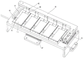
FIG. 1 is a schematic structural view of the present invention;
FIG. 2 is a partial schematic view of the present invention;
FIG. 3 is a second partial schematic view of the present invention;
FIG. 4 is a third schematic view of a partial structure of the present invention;
FIG. 5 is a fourth partial schematic view of the present invention;
FIG. 6 is a schematic view of the structure of the material supporting mechanism of the present invention;
FIG. 7 is a schematic structural view of a positioning mechanism of the present invention;
fig. 8 is a schematic structural diagram of the material inserting manipulator of the present invention;
FIG. 9 is a schematic view of a take-out mechanism of the present invention;
FIG. 10 is a schematic structural view of the support mechanism of the present invention;
FIG. 11 is a schematic structural view of the ejector mechanism of the present invention;
fig. 12 is a schematic structural view of the stock stop of the present invention.
In the figure: 100. a frame; 110. a material supporting frame; 111. a workpiece; 120. a material inserting frame; 121. a slot; 10. a feeding mechanism; 11. a stacking space; 12. a support mechanism; 13. a first height sensor; 14. a first driving cylinder; 15. a clamping block; 16. a support bar; 17. a second driving cylinder; 18. a third driving cylinder; 20. a material taking station; 21. a material taking mechanism; 211. taking a material part; 212. a first drive mechanism; 213. a second drive mechanism; 241. a first fixing frame; 22. a stock stop mechanism; 221. a striker plate; 222. a fifth driving cylinder; 30. a blanking mechanism; 31. a material supporting space; 32. a material ejecting mechanism; 33. a top rod; 34. a blocking block; 35. a fourth drive cylinder; 40. a positioning mechanism; 41. positioning blocks; 42. a first stopper; 43. a second limiting block; 44. a first guide groove; 45. a second guide groove; 46. a third manipulator; 47. a fourth manipulator; 50. a material inserting manipulator; 51. a first driving device; 511. a drive motor; 512. a rotating shaft of the driving motor; 52. an articulated robot; 53. a gripping device; 531. a second fixing frame; 532. a second vacuum chuck; 54. a camera; 61. inserting a material slot position; 62. a second conveying mechanism; 621. a third drive mechanism; 622. a transfer arm; 63. a material supporting mechanism; 631. a sixth driving cylinder; 632. a connecting frame; 633. a support sheet; 64. an elastic member; 65. a position limiter; 66. a jacking mechanism; 70. a conveying table; 71. a conveying rack; 80. a first conveying mechanism; 90. a guide mechanism.
Detailed Description
The invention will be further described with reference to the accompanying drawings and the detailed description below:
the automatic loading and unloading system shown in fig. 1-5 comprises a rack 100, a first conveying mechanism 80, a loading mechanism 10, a material taking mechanism 21, an unloading mechanism 30, a positioning mechanism 40 and an inserting manipulator 50, wherein the rack 100 is provided with a loading station, a material taking station 20, a positioning station, an unloading station and an inserting slot station 61. The feeding station, the material taking station 20 and the blanking station may be sequentially arranged along the conveying direction of the first conveying mechanism 80.
A stacking space 11 is provided at the loading station, the stacking space 11 is used for stacking a plurality of material holders 110 loaded with workpieces 111, and the material holders 110 are stacked along the height direction of the stacking space 11. A discharge hole is formed at the bottom end of the stacking space 11. Meanwhile, a material supporting space 31 is arranged at the discharging station, and a material inlet is correspondingly arranged at the bottom end of the material supporting space 31; and a blocking station for blocking the empty material supporting frame 110 is arranged at the material inlet. The starting end of the first conveying mechanism 80 is connected to the discharge port at the bottom end of the stacking space 11 and is used for receiving the material supporting frame 110 output from the discharge port, and the tail end of the first conveying mechanism 80 is connected to the material inlet at the bottom end of the material supporting space 31. The starting end of the first conveying mechanism 80 is connected to the discharge port at the bottom end of the stacking space 11 and is used for receiving the material supporting frame 110 output from the discharge port, and the tail end of the first conveying mechanism 80 is connected to the material inlet at the bottom end of the material supporting space 31. In addition, the insert slot position 61 is used for placing an insert rack (i.e., a wash rack) with an insert slot 121.
The feeding mechanism 10 may be specifically installed at the feeding station, and the feeding mechanism 10 includes a clamping mechanism and a supporting mechanism 12, and the clamping mechanism may be used to clamp or release the material holder 110 located at the bottom end of the stacking space 11. The support mechanism 12 can move towards or away from the discharging hole, and when the support mechanism 12 moves towards the discharging hole, the support mechanism 12 abuts against the material holding frame 110 at the bottommost end of the stacking space 11.
In addition, the material taking mechanism 21 is installed at the material taking station 20, and the material taking mechanism 21 is used for clamping the workpiece 111 on the material support frame 110 at the material taking station 20 to the positioning station. The positioning mechanism 40 may be installed at a positioning station for positioning the workpiece 111 transferred from the material taking mechanism 21. Meanwhile, the inserting robot 50 may be configured to pick up the workpiece 111 at the positioning station and turn the workpiece 111 to insert the turned workpiece 111 into the slot 121 of the inserting frame 120.
The discharging mechanism 30 comprises a material ejecting mechanism 32 and a blocking mechanism, the material ejecting mechanism 32 is located below the material inlet, the material ejecting mechanism 32 can move towards or away from the material inlet, and the material ejecting mechanism 32 can upwards eject the empty material supporting frame 110 when moving towards the material inlet, so that the empty material supporting frame 110 moves into the material supporting space 31. In addition, the blocking mechanism may move toward or away from the blocking station, and may block the empty tray 110 when the blocking mechanism moves toward the blocking station.
In this embodiment, a plurality of glass screens are loaded on the material support frame 110, and the automatic up-and-down system is used to take down the plurality of glass screens and turn over the glass screens so that the glass screens are inserted into the slots 121 in the material support frame 120 in a vertical state.
On the basis of the structure, a plurality of material supporting frames 110 loaded with a plurality of glass screens can be stacked in the stacking space 11 in advance, and when the material loading operation is not carried out, the clamping mechanism clamps the edge of the material supporting frame 110 at the lowest end of the stacking space 11, so that the material supporting frames 110 are prevented from falling off. When the loading operation is started, the supporting mechanism 12 can move towards the direction close to the discharge hole, at this time, the supporting mechanism 12 can abut against the material supporting frame 110 located at the lowest end of the stacking space 11, and the material supporting frame 110 cannot fall off from the discharge hole. Meanwhile, the clamping mechanism is loosened from the material supporting frame 110 located at the lowest end of the stacking space 11, then the supporting mechanism 12 moves towards the direction away from the material outlet, the material supporting frame 110 is far away from the material outlet along with the supporting mechanism 12 under the action of the self gravity, and the clamping mechanism is clamped on the material supporting frame 110 adjacent to the material supporting frame 110 located at the lowest end of the stacking space 11 again, so that only one material supporting frame 110 falls onto the initial end of the first conveying mechanism 80 along with the material supporting frame 110 in the process of continuously keeping away from the material outlet by the supporting mechanism 12, and the process is repeated and the material can be continuously fed.
After the material supporting frame 110 loaded with a plurality of glass screens falls on the starting end of the first conveying mechanism 80, the first conveying mechanism 80 can convey the material supporting frame 110 to the material taking station 20, the material taking mechanism 21 can take off the plurality of glass screens on the material supporting frame 110, the taken-off glass screens are transferred to the positioning station, and the positioning mechanism 40 arranged at the positioning station can position the glass screens, so that the glass screens are placed neatly, and the inserting manipulator 50 can grab the glass screens accurately. After grabbing the glass screen, the material inserting manipulator 50 can turn over the glass screen to make the glass screen turn over to be in a vertical state, and then the material inserting manipulator 50 can insert the turned glass screen into the insertion slot 121 of the material inserting frame 120 at the material inserting groove 61 to complete the material inserting operation. Repeating the above steps, and uniformly cleaning the glass screen after the glass screen is fully inserted into the inserting frame 120.
In addition, during the above operations, that is, after the material taking mechanism 21 takes off a plurality of glass screens, the remaining empty material supporting frame 110 can be continuously conveyed to the material discharging station under the action of the first conveying mechanism 80, the remaining empty material supporting frame 110 can be conveyed to the material inlet at the bottom end of the material supporting space 31, at this time, the material ejecting mechanism 32 moves upwards, that is, moves towards the material inlet, that is, the material ejecting mechanism 32 can upwards eject the empty material supporting frame 110, and at the same time, the blocking station can move towards the direction far away from the material inlet, so that the empty material supporting frame 110 can move into the material supporting space 31 from the material inlet. After that, the blocking mechanism moves towards the direction close to the blocking station, and the ejecting mechanism 32 moves towards the direction away from the feeding port (i.e. downwards), at this time, the blocking mechanism blocks the empty material supporting frame 110, that is, the empty material supporting frame 110 is blocked by the blocking mechanism and cannot fall off due to self gravity. So relapse, the empty support work or material rest 110 of being carried by first conveying mechanism 80 can be one and is piled up in getting into support material space 31 by the pan feeding mouth, accomplishes the unloading operation fast, and degree of automation is high.
Preferably, referring to fig. 10, the supporting mechanism 12 includes a first driving cylinder 14, a first supporting plate and a supporting rod 16, the first supporting plate is fixedly connected to a piston rod of the first driving cylinder 14, a bottom end of the supporting rod 16 is fixedly connected to the first supporting plate, and a top end of the supporting rod 16 forms a supporting end, and the supporting end is used for moving towards or away from the discharge hole. On the basis of the structure, the piston rod of the first driving cylinder 14 drives the first supporting plate to stretch, and in the stretching process of the first supporting plate, the supporting end is driven to be close to or far away from the discharging hole, so that the supporting operation of the material supporting frame 110 in the feeding process is completed. Of course, the support bar 16 may be provided in plural, and the support structure is more stable.
Further, the supporting mechanism 12 further includes a third driving cylinder 18 and a second supporting plate, wherein a cylinder body of the third driving cylinder 18 is mounted on the frame 100, and a piston rod of the third driving cylinder 18 is fixedly connected to the second supporting plate. On the basis of this structure, the cylinder body of the first driving cylinder 14 is mounted on the second support plate. Furthermore, the movement stroke of the third drive cylinder 18 is smaller than the movement stroke of the first drive cylinder 14. Therefore, the first driving air cylinder 14 and the second driving air cylinder 17 can be matched with each other, when the supporting rod 16 is driven to move close to the material supporting frame 110 at the beginning, the movement distance of the first supporting rod 16 can be increased through the combined action of the first driving air cylinder 14 and the third driving air cylinder 18. When the support rod 16 moves away from the material support frame 110, the support rod can move only after the clamping mechanism clamps the previous material support frame 110 again, at this moment, the piston rod of the third driving cylinder 18 can be contracted to drive the support rod 16 to move a small distance away from the material outlet, and after the clamping mechanism clamps stably, the piston rod of the first driving cylinder 14 is contracted to make the material support frame 110 fall on the first conveying mechanism 80, so that the feeding process is gradually followed, and the movement stroke is more flexible and adjustable.
Further, in this embodiment, referring to fig. 3, the clamping mechanism includes a plurality of second driving cylinders 17 and a plurality of clamping blocks 15, the plurality of second driving cylinders 17 are mounted on the frame 100 and circumferentially arrayed around the central axis of the stacking space 11, the plurality of clamping blocks 15 are fixedly connected to the piston rods of the plurality of second driving cylinders 17 in a one-to-one correspondence manner, specifically, there are four second driving cylinders 17, four corresponding clamping blocks 15 are provided, and the four second driving cylinders 17 are respectively provided at four corners of the stacking space 11. When the work is not started, the four clamping blocks 15 can move towards the inside of the stacking space 11 under the driving of the four second driving cylinders 17, so that the four clamping blocks 15 are located below the material supporting frame 110 to support the material supporting frame 110, and the clamping operation is completed. And when material loading, supporting mechanism 12 withstands support work or material rest 110 earlier, makes four grip blocks 15 keep away from and pile up inside space 11, and support work or material rest 110 can fall, accomplishes the material loading. This is repeated. Of course, each clamping block 15 can also abut against the edge of the carrier frame 110 during the movement towards the inside of the stacking space 11, and the clamping operation can also be completed.
Preferably, referring to fig. 3, the blocking mechanism includes a plurality of blocks 34, the plurality of blocks 34 are disposed at the blocking station, and the plurality of blocks 34 are movable toward or away from the blocking station to block the empty holders 110 when the plurality of blocks 34 are moved toward the blocking station. On the basis of the mechanism, when the material ejecting mechanism 32 ejects the empty material supporting frame 110 upwards, the blocking blocks 34 can move towards the direction away from the material inlet, so that the empty material supporting frame 110 can move into the material supporting space 31 from the material inlet. After that, the blocking blocks 34 move towards the direction close to the blocking station, and the ejecting mechanism 32 moves towards the direction away from the feeding port, at this time, the blocking blocks 34 block the empty material supporting frame 110, that is, the empty material supporting frame 110 is blocked by the blocking blocks 34, and cannot fall off due to self gravity, and the process is repeated.
Preferably, each of the blocking blocks 34 may be pivotally connected to a sidewall of the material inlet, and each of the blocking blocks 34 may rotate towards a direction close to or away from the material inlet under the action of an external force. Therefore, when the material ejecting mechanism 32 moves towards the direction close to the material inlet, the empty material supporting frame 110 is ejected upwards, and the blocking block 34 is ejected upwards in the upward movement process of the empty material supporting frame 110, so that the blocking block 34 rotates towards the direction far away from the material inlet, and the empty material supporting frame 110 can smoothly enter the material supporting space 31 for stacking. Thereafter, the blockable block 34 can be reset under its own weight and moved toward the direction close to the feeding port, thereby completing the blocking operation, so that the empty holders 110 are stacked in the holder space 31. Of course, in this embodiment, the blocking block 34 is pivotally connected to the sidewall of the feeding port through a rotating shaft, so that the blocking block 34 is in interference fit with the rotating shaft, and has a certain damping force, and thus the blocking block 34 can only rotate under the condition of a large enough external force, and can automatically return to the horizontal state under its own gravity. Of course, the blocking block 34 can also be made to extend into the material inlet by the expansion of the cylinder or retract into the side wall of the material inlet, and the above operation can also be realized.
Preferably, the bottom end of the blocking block 34 is provided with a pressed inclined plane, and the pressed inclined plane is gradually inclined from top to bottom towards the direction far away from the feeding port; the pressure-receiving slope is pressed by an external force to move the stopper 34 in a direction away from the inlet. That is, when the empty holder 110 is pressed upward by the material pressing mechanism 32, the edge of the empty holder 110 presses the inclined pressing surface, so that the inclined pressing surface decomposes the force into a vertical force that moves the stopper 34 upward and a horizontal force that retracts the stopper 34, thereby facilitating driving.
In the present embodiment, referring to fig. 11, the ejector mechanism 32 includes a fourth driving cylinder 35, a connecting plate, and a plurality of ejector rods 33. The concrete connecting plate rigid coupling is on the top of fourth drive cylinder 35, and the piston rod of fourth drive cylinder 35 can be towards being close to keep away from the direction motion of pan feeding mouth, a plurality of ejector pins 33 rigid coupling is on the connecting plate and is used for the empty work or material rest 110 of top pressure. On this mechanism basis, through starting fourth actuating cylinder 35, can drive the up-and-down motion of piston rod, so can drive connecting plate up-and-down motion to drive a plurality of ejector pins 33 on the connecting plate and move towards being close to or keeping away from the pan feeding mouth, accomplish the effect of the empty work or material rest 110 that holds in the palm of propelling movement. And a plurality of ejector rods 33 are adopted, so that the stress of the empty material holding frame 110 is more uniform.
Preferably, referring to fig. 9, the material taking mechanism 21 includes a plurality of material taking members 211 for sucking the workpiece 111, a first driving mechanism 212 and a second driving mechanism 213, and the first driving mechanism 212 can drive the plurality of material taking members 211 to move toward or away from the material taking station 20 along the width direction of the frame 100. Meanwhile, the second driving mechanism 213 may drive the plurality of material taking members 211 to move toward or away from the material taking station 20 along the height direction of the rack 100. Therefore, the second driving mechanism 213 can drive the plurality of material taking members 211 to move in the height direction of the rack 100, and the plurality of glass screens on the material supporting frame 110 can be taken down at one time. After that, the first driving mechanism 212 drives the plurality of material taking members 211 to move along the width direction of the rack 100, so that a plurality of glass screens at another position on the material supporting frame 110 can be taken down, and the material taking at different positions of the material taking station 20 can be realized. It should be noted that, the material taking part 211 may specifically adopt a plurality of first vacuum chucks, and the plurality of first vacuum chucks are arranged at intervals along the width direction of the rack 100, and the workpiece 111 may be stably transferred by using a manner that the plurality of first vacuum chucks suck the workpiece 111, and the surface of the workpiece 111 may not be damaged. Of course, the material taking member 211 can be replaced by a clamping jaw, a pneumatic finger or other members with clamping function.
The first driving mechanism 212 is a first robot, the second driving mechanism 213 is a second robot, and the plurality of material-taking members 211 are fixed to a power output end of the second robot through a first fixing frame 241, and the second robot is mounted to a power transmission end of the first robot. So, accessible second manipulator drives first mount 241 up-and-down motion (the direction of height of frame 100 promptly) to drive a plurality of material 211 of getting and absorb work piece 111, then drive the second manipulator seesaw (the width direction of frame 100 promptly) through first manipulator and alright drive a plurality of material 211 of getting and remove to the different positions of getting material station 20, accomplish the above-mentioned material operation of getting. Of course, the first driving mechanism 212 and the second driving mechanism 213 can be replaced by other transmission mechanisms such as an air cylinder, an oil cylinder, or a sliding device.
Preferably, referring to fig. 3 and 12, a material blocking station and a material blocking mechanism 22 are further disposed on the machine frame 100, so that the material blocking station is located between the material taking station 20 and the material discharging station, the material blocking mechanism 22 can move towards the material blocking station or away from the material blocking station, and the material blocking mechanism 22 is used for blocking the material support frame 110 when moving towards the material blocking station. On this structure basis, when the work or material rest 110 that loads a plurality of glass screens carries along the direction of delivery of first conveying mechanism 80, work or material rest 110 can be through keeping off the material station, can make the stock stop 22 move towards being close to keeping off the material station this moment, makes stock stop 22 block above-mentioned work or material rest 110, prevents that work piece 111 from carrying the head, can prescribe a limit to the position of work or material rest 110, realizes the location. After the plurality of glass screens on the material holding frame 110 are all taken down, the plurality of material blocking mechanisms 22 can move towards the direction far away from the material blocking stations, and the empty material holding frame 110 after the material is taken out can be continuously conveyed to the next station. So relapse, hold in the palm the work or material rest 110 at every turn and carry and all can be kept in the material taking station 20 by stock stop 22 and let go after a period of time, can realize holding in the palm the location of work or material rest 110 and get the material, degree of automation is high, gets the material efficient.
Preferably, a position sensor can be further arranged at the material blocking station, the position of the workpiece 111 is detected through the position sensor, a position signal is sent to the material blocking mechanism 22, and the material blocking mechanism 22 can move towards the material blocking station to block the workpiece 111 according to the position signal, so that the control is convenient, and the real-time positioning is realized.
Preferably, in this embodiment, referring to fig. 12, the material blocking mechanism 22 may include a fifth driving cylinder 222 and a material blocking plate 221, and specifically, the fifth driving cylinder 222 is configured to drive the material blocking plate 221 to move towards a material blocking station along a height direction of the frame 100 according to a position signal sent by the position sensor, so as to implement material blocking operation. Of course, the striker plate 221 may be driven by a linear motor or a robot.
Preferably, the automatic loading and unloading mechanism 30 further includes a first height sensor 13 and a second height sensor (not shown) mounted on the frame 100, wherein the first height sensor 13 is mounted at the loading station for detecting the height of the plurality of carriers 110 containing the workpieces 111 in the stacking space 11 and transmitting a first height signal. So, in the in-process that the work or material rest 110 is exported by the discharge gate in proper order at the work or material rest 110, the height that piles up the work or material rest 110 in the space 11 can reduce gradually, when reducing to certain altitude value, the height of a plurality of work or material rests 110 of first height sensor 13 detectable this moment, when a plurality of work or material rests 110 highly be less than a definite value, can send first height signal, in order to remind the operator to hold in the palm the quantity condition of work or material rest 110, the operator of being convenient for in time supplyes the work or material rest 110, so can make work or material rest 110 keep certain quantity throughout, realize continuously carrying automatically, degree of automation is high.
In addition, the second height sensor is arranged at the blanking station and used for detecting the height of the material supporting frame 110 in the material supporting space 31 and sending a second height signal. That is, after a plurality of empty holders 110 continuously enter the holder space 31, the height of the empty holders 110 in the holder space 31 is gradually increased, and when the height of the plurality of empty holders 110 reaches a certain value, a second height signal can be sent to remind an operator to take off the stacked empty holders 110 in time, so as to avoid the tray turnover caused by too many empty holders 110 stacked.
Of course, a controller may be provided on the frame 100, and the controller may receive the first height signal and the second height signal, and the height value may be set in advance. In addition, in the absence of a controller, the first and second height signals transmitted may be alarm signals that sound to alert the operator. It should be noted that, the height sensor may be one of a potentiometer type sensor, a grating type angle sensor, a magnetic grating type angle sensor, and a code wheel type sensor in the prior art.
Preferably, the automatic loading and unloading mechanism 30 further includes a guiding mechanism 90, and the guiding mechanism 90 can be used for guiding the material holding frame 110 to be conveyed along the conveying direction of the first conveying mechanism 80, so that the movement process is smoother. Specifically, guiding mechanism 90 can include a plurality of guide rollers, specifically all is equipped with a plurality of guide rollers in the both sides of first conveying mechanism 80, and a plurality of guide rollers arrange along the direction of delivery of first conveying mechanism 80, when holding in the palm work or material rest 110 by first conveying mechanism 80 transport, above-mentioned a plurality of guide rollers can roll the cooperation with the edge that holds in the palm work or material rest 110 to make hold in the palm work or material rest 110 can be carried steadily, and transportation process is more smooth and easy.
Preferably, in the present embodiment, referring to fig. 8, the material inserting manipulator 50 specifically includes a gripping device 53, a visual positioning device, a first driving device 51, and a second driving device. The clamping device 53 is used for clamping the workpiece 111 at the feeding station, and the first driving device 51 is used for driving the clamping device 53 to turn over, that is, driving the workpiece 111 on the clamping device 53 to turn over. Meanwhile, the vision positioning device is used for photographing the blanking station and sending a picture signal, and the second driving device can drive the clamping device 53 to move from the feeding station to the blanking station according to the picture signal.
On the basis of the structure, the glass screen of the positioning station is clamped by the clamping device 53, and then the clamping device 53 is driven to turn over by the first driving device 51, so that the glass screen can be driven to turn over from the horizontal state to the vertical state. Meanwhile, the position of the slot 121 of the inserting frame 120 can be photographed by the visual positioning device and a picture signal can be sent, and after the position of the slot 121 of the inserting frame 120 is detected, the second driving device drives the clamping device 53 to move from the positioning station to the slot 121 of the inserting frame 120, so that the glass screen can be driven to be inserted into the slot 121 of the inserting frame 120, and the inserting operation is completed. That is, the robot can complete the operation of turning the workpiece 111 and accurately transfer the workpiece into the slot 121, thereby improving efficiency.
Preferably, in this embodiment, the second driving device is an articulated robot 52, and the articulated robot 52 is configured to receive the picture signal. In addition, the clamping device 53 includes a second fixing frame 531 and a plurality of second vacuum suction cups 532, the plurality of second vacuum suction cups 532 are installed on the second fixing frame 531, the second fixing frame 531 is installed at the power output end of the joint robot 52, and the first driving device 51 is used for driving the second fixing frame 531 to overturn. On the basis of the structure, the workpiece 111 can be sucked by the plurality of second vacuum chucks 532, then the first driving device 51 is started to overturn the second fixing frame 531, and the plurality of second vacuum chucks 532 sucking the workpiece 111 can be driven to overturn in the process of overturning the second fixing frame 531, so that the overturning operation of the workpiece 111 is completed. Thereafter, the joint robot 52 can drive the second fixing frame 531 to move to the slot 121 according to the picture signal, thereby completing the transferring operation. It should be noted that the plurality of second vacuum chucks 532 can be used for sucking the workpiece 111, so that the workpiece 111 can be smoothly transferred without damaging the surface of the workpiece 111. The joint robot 52 can make the gripping device 53 have more freedom of movement in multiple directions, and can be changed conveniently according to the picture signal. The specific joint robot 52 can be a five-axis or six-axis joint robot 52, and the flexibility is higher. Of course, the gripping device 53 may be a gripping jaw or the like, in addition to the above-described implementation. Similarly, the second driving device may be implemented by using a driving mechanism capable of outputting a plurality of linear motions.
Preferably, the first driving device 51 is a driving motor 511, the body of the driving motor 511 is fixed on the power output end of the joint robot 52, and the rotating shaft 512 of the driving motor is fixedly connected with the fixing frame 531241. The driving motor 511 drives the fixing frame 531241 to rotate, and then drives the plurality of second vacuum suction cups 532 to rotate, thereby implementing the above-mentioned turning operation. Of course, the first driving device 51 may be replaced by a gear mechanism or other driving mechanism capable of outputting a rotational motion.
Preferably, the visual positioning device is a camera 54, the camera 54 is fixedly connected to the joint robot 52, the slot 121 is photographed and positioned by the camera 54, and then a picture signal is transmitted to the joint robot 52. Of course, other devices such as sensors and other sensing mechanisms may be used for visual positioning.
Preferably, in this embodiment, the curve that its self surface of longitudinal section intercepting of above-mentioned first vacuum chuck and second vacuum chuck 532 becomes is the wavy line, that is to say, the surface of first vacuum chuck and second vacuum chuck 532 can be equipped with a plurality of folds, because first vacuum chuck and second vacuum chuck 532 are generally made by rubber material, therefore it can be better at first vacuum chuck and second vacuum chuck 532 absorption work in-process cushioning effect to be equipped with a plurality of folds, can not produce and absorb the action process and take place direct striking, avoid work piece 111 impaired.
Preferably, referring to fig. 4 and 6, the automatic loading and unloading system may further include a material supporting mechanism 63, wherein the material supporting mechanism 63 is located below the material inserting position 61 and is configured to move toward the inside of the material inserting position 61 or away from the material inserting position. So, when inserting the material operation, can make hold in the palm material mechanism 63 earlier towards inserting the inside motion of material trench 61, hold in the palm the work piece 111 in the slot 121 that material frame 120 can be inserted to holding in the material mechanism 63 protractile earlier, then make hold in the palm material mechanism 63 gradually towards keeping away from inserting the motion of material trench 61, drive work piece 111 slowly and get into in the slot 121, therefore work piece 111 can be by steady insertion, insert the material operation with the material manipulator 50 need not to stretch into inside slot 121 completely, avoid inserting material manipulator 50 and insert the material frame 120 and collide.
The material supporting mechanism 63 in this embodiment includes a sixth driving cylinder 631, a connecting frame 632, and a plurality of supporting sheets 633, the plurality of supporting sheets 633 are fixedly connected to the connecting frame 632, and the sixth driving cylinder 631 is configured to drive the connecting frame 632 to move toward or away from the material inserting slot 61, so that the plurality of supporting sheets 633 extend into or away from the material inserting slot 121 of the material inserting frame 120. That is to say, during the inserting operation, the sixth driving cylinder 631 can drive the plurality of supporting sheets 633 to move towards the inserting trough 61, and the plurality of supporting sheets 633 can extend into the inserting trough 121, that is, the height of the supporting sheet 633 is higher than the bottom of the inserting trough 121, so that the inserting manipulator 50 places the workpiece 111 in the inserting trough 121, and the bottom of the workpiece 111 contacts with the top of the supporting sheet 633, so that the inserting manipulator 50 does not need to enter the inserting trough 121. The plurality of blades 633 are then moved away from the slot station 61, during which the workpiece 111 drops into the slot 121, completing the fixture.
Preferably, referring to fig. 4 and 5, the automatic loading and unloading system further includes a conveying table 70 mounted on the frame 100 and a second conveying mechanism 62, wherein a plurality of conveying racks 71 are disposed on the conveying table 70, the plurality of conveying racks 71 are arranged at intervals along the height direction of the frame 100, and the conveying racks 71 can be used for placing the insert rack 120 with the insert slot 121. In addition, the plurality of conveying carriages 71 may be movable in the height direction of the conveying table 70. And a second conveyor mechanism 62 can be used to transport the insert carriers 120 on the transfer gantry 71 to the insert slot 61.
In addition to the above configuration, the insert frame 120 having the insert slot 121 may be placed on each of the transfer stages 71 of the transfer table 70, and the insert frame 120 on the transfer stage 71 positioned at the topmost end may be transferred into the insert slot 61 by the second transfer mechanism 62, and the workpiece 111 may be inserted into the insert slot 121 by the insert robot 50 to complete the automatic insert. After completing the inserting operation of one inserting frame 120, the inserting frame 120 can be conveyed to the conveying racks 71 again by the second conveying mechanism 62, and then the conveying racks 71 are moved upward along the height direction of the rack 100, that is, the empty inserting frame 120 is lifted up, and at this time, the inserting frame 120 is conveyed to the inserting position 61 by the second conveying mechanism 62, so that the inserting operation is completed, and the operation is repeated, and the automation degree is higher.
In this embodiment, the second conveying mechanism 62 specifically includes a conveying arm 622 and a third driving mechanism 621, the third driving mechanism 621 drives the conveying arm 622 to move toward or away from the conveying table 70, and when the conveying arm 622 moves toward and close to the conveying table 70, the conveying arm 622 can extend below the conveying table 71 to support the material inserting frame 120. And the transfer arm 622 moves the inserting frame 120 to the inserting position 61 when moving away from the transfer table 70. Specifically, during the material inserting operation, the third driving mechanism 621 can drive the conveying arm 622 to move toward the conveying table 70, and when the conveying arm 622 moves below the conveying tables 71, the conveying tables 71 can move downward, so that the material inserting frames 120 fall on the conveying arm 622, and at this time, the conveying arm 622 moves in a direction away from the conveying tables 70, and the material inserting frames 120 can be driven to move toward the material inserting positions 61. After the material insertion is completed, the conveying arm 622 can be moved toward the direction close to the conveying table 70, so that the conveying arm 622 can drive the material insertion frame 120 full of inserted workpieces 111 to move above the conveying tables 71, at this time, the plurality of conveying tables 71 can move upwards, and the material insertion frame 120 can be separated from the conveying arm 622. This operation is repeated to complete the insertion operation of the plurality of insertion frames 120 on the conveying table 71.
Preferably, an elastic member 64 is disposed at a side of the material inserting groove 61 away from the conveying table 70, and in the process that the conveying arm 622 drives the material inserting frame 120 to move away from the conveying table 70, the material inserting frame 120 will press against the elastic member 64, so that a hard collision between the material inserting frame 120 and the rack 100 can be avoided. Of course, after the material insertion, the elastic member 64 is reset to provide an acceleration to the material insertion frame 120 for driving. In this embodiment, the elastic member 64 may be a spring.
More specifically, a pressing mechanism 66 may be disposed on one side of the inserting position 61, the pressing mechanism 66 may move toward or away from the inserting position 61, and when the inserting frame 120 is on the inserting position 61 and is ready to insert, the pressing mechanism 66 may move toward the inserting position 61, so that the pressing mechanism 66 may abut against one side of the inserting frame 120, so that the inserting frame 120 is stably located in the inserting position 61 and is prevented from deflecting during the inserting process. The pressing mechanism 66 may include a contact plate and a driving cylinder, and the driving cylinder drives the contact plate to move toward or away from the material inserting slot 61.
Preferably, a position limiter 65 is further disposed at a side of the inserting slot 61 close to the conveying table 70, the position limiter 65 is used for detecting the position of the inserting frame 120 and sending a signal, so that after the inserting slot 61 completely enters the inserting slot 61, the position limiter 65 can send a signal to the inserting manipulator 50 to start the operation of the material taking manipulator.
Referring to fig. 7, the positioning mechanism 40 in this embodiment includes a positioning table, a first stopper 42, a second stopper 43, a first guide groove 44, and a second guide groove 45; the first stopper 42, the second stopper 43, the first guide groove 44, and the second guide groove 45 may be installed on the positioning table. A positioning groove is formed in the positioning table, and the positioning groove can be used for mounting the workpiece 111. Specifically, the first stopper 42 may move toward the positioning slot along the width direction of the positioning table, and the second stopper 43 may move toward the positioning slot along the length direction of the positioning table. The first guide groove 44 is used for guiding the first limiting block 42 to move towards the direction close to the positioning slot along the length direction of the positioning table, and similarly, the second guide groove 45 is used for guiding the second limiting block 43 to move along the width direction of the positioning table.
After the material taking mechanism 21 takes the material, the glass screen can be placed in the positioning groove, the first limiting block 42 is moved to the end part of the workpiece 111, and the second limiting block is moved to the side part, so that the end surface and the side surface of the workpiece 111 are abutted to the end wall and the side wall of the positioning groove, the workpiece 111 can be placed neatly in the positioning groove, and the inserting manipulator 50 can be conveniently and accurately grabbed. And the motion direction of the first limiting block 42 and the second limiting block 43 is two completely vertical directions, so that the glass screen installed in the positioning slot position is in a completely attached state, the situation of deflection in the grabbing process can not occur, and the grabbing effect is better.
It should be noted that, in this embodiment, the positioning slot may be a groove provided on the positioning table, and the groove has an end wall and a side wall. Based on this, when the first stopper 42 and the second stopper 43 are abutted to the glass screen, the first stopper 42 and the second stopper 43 may form another end wall and another side wall of the groove. Of course, the positioning slot may be only one open station, two first limiting blocks 42 may be provided at this time, and two second limiting blocks 43 may be provided at the same time, so that two first limiting blocks 42 may move in pairs, and two second limiting blocks 43 may move in pairs, and the two first limiting blocks 42 and the two second limiting blocks 43 may also jointly form the positioning slot. Of course, the positioning slot position can be formed in other ways.
Furthermore, a plurality of positioning blocks 41 are arranged on the positioning table, the positioning blocks 41 are arranged along the length direction of the positioning table, and a positioning slot is formed on the top end surface of each positioning block 41. That is, the positioning table is provided with a plurality of positioning slots, so that the positioning work of a plurality of glass screens can be completed at the same time. Of course, on the basis of this structure, the first limiting block 42, the second limiting block 43, the first guide groove 44 and the second guide groove 45 are uniformly and correspondingly arranged on each positioning block 41, so that each positioning block 41 can independently complete the positioning operation without mutual influence.
Further, a third manipulator 46 is further arranged on the positioning table, the third manipulator 46 is used for driving the first limiting block 42 to move along the width direction of the positioning table, and the driving structure is stable and simple. Similarly, still be equipped with fourth manipulator 47 on the locating platform, fourth manipulator 47 is used for driving the length direction motion of second stopper 43 along the locating platform, and same drive stable in structure is just simple, the drive of being convenient for.
Various other modifications and changes may be made by those skilled in the art based on the above-described technical solutions and concepts, and all such modifications and changes should fall within the scope of the claims of the present invention.
Claims (9)
1. The automatic loading and unloading system is characterized by comprising,
the automatic feeding device comprises a rack, wherein a feeding station, a taking station, a positioning station, a discharging station and a material inserting groove are arranged on the rack; a stacking space is arranged at the feeding station and used for stacking a plurality of material supporting frames loaded with workpieces along the height of the stacking space; a discharge port is formed at the bottom end of the stacking space; a material supporting space is arranged at the blanking station, and a feeding port is arranged at the bottom end of the material supporting space; a blocking station for blocking an empty material supporting frame is arranged at the material inlet; the inserting groove is used for placing an inserting frame with an inserting groove;
the starting end of the first conveying mechanism is connected with the discharge port and used for receiving the material supporting frame output by the discharge port, and the tail end of the first conveying mechanism is connected with the material inlet;
the feeding mechanism comprises a clamping mechanism and a supporting mechanism, and the clamping mechanism is used for clamping or loosening the material supporting frame positioned at the bottommost end of the stacking space; the supporting mechanism is used for abutting against the material supporting frame positioned at the bottommost end of the stacking space when moving towards the material outlet;
the material taking mechanism is used for clamping a workpiece on the material supporting frame at the material taking station to a positioning station;
the blanking mechanism comprises a material ejecting mechanism and a blocking mechanism, and the material ejecting mechanism is positioned below the material inlet and can move towards or away from the material inlet; the material ejecting mechanism is used for ejecting the empty material supporting frame when moving towards the material inlet so as to enable the material supporting frame to move into the material supporting space; the blocking mechanism can move towards the direction close to or far away from the blocking station; the blocking mechanism is used for blocking the material supporting frame when moving towards the blocking station;
a positioning mechanism for positioning a workpiece;
the inserting manipulator is used for clamping the workpiece at the positioning station and overturning the workpiece so as to insert the overturned workpiece into the slot of the inserting frame;
the automatic feeding and discharging system also comprises a conveying table and a second conveying mechanism which are arranged on the rack, wherein a plurality of conveying racks are arranged on the conveying table and are arranged at intervals along the height direction of the rack; the conveying rack is used for placing an inserting rack with slots; the plurality of conveying platforms can move along the height direction of the conveying platforms; the second conveying mechanism is used for conveying the material inserting frame on the conveying rack to the material inserting groove; the second conveying mechanism comprises a conveying arm and a third driving mechanism, the third driving mechanism drives the conveying arm to move towards the direction close to or far away from the conveying table, and when the conveying arm moves towards the direction close to the conveying table, the conveying arm can extend into the lower part of the conveying table frame to support the material inserting frame; and the conveying arm can drive the material inserting frame to move to the material inserting groove position when moving away from the conveying table.
2. The automatic loading and unloading system of claim 1, wherein the support mechanism comprises a first driving cylinder, a first support plate and a support rod, the first support plate is fixedly connected to a piston rod of the first driving cylinder, the bottom end of the support rod is fixedly connected to the first support plate, and the top end of the support rod forms a support end which is used for moving towards or away from the discharge hole.
3. The automatic loading and unloading system of claim 1, wherein the clamping mechanism comprises a plurality of second driving cylinders and a plurality of clamping blocks, the plurality of second driving cylinders are mounted on the frame and circumferentially arrayed around the central axis of the stacking space, the plurality of clamping blocks are fixedly connected to piston rods of the plurality of second driving cylinders in a one-to-one correspondence manner, and each clamping block can move towards the inside of the stacking space or away from the stacking space.
4. The automatic loading and unloading system of claim 1, wherein the blocking mechanism comprises a plurality of blocking blocks, the plurality of blocking blocks are arranged at the blocking station and can move towards the direction close to or far away from the blocking station; the blocking blocks are used for blocking the material holding frame when moving towards the blocking station; each blocking block is pivoted on the side wall of the feeding opening and can rotate towards the direction close to or far away from the feeding opening under the action of external force; the bottom end of the blocking block is provided with a pressed inclined plane which is gradually inclined towards the direction far away from the material inlet from top to bottom; the pressed inclined surface is pressed by external force so that the blocking block rotates towards the direction far away from the feeding port.
5. The automatic loading and unloading system of claim 1, wherein the material taking mechanism comprises a plurality of material taking parts for sucking the workpieces, a first driving mechanism and a second driving mechanism, the first driving mechanism is used for driving the plurality of material taking parts to move towards or away from the material taking station along the width direction of the rack; the second driving mechanism is used for driving the plurality of material taking parts to move towards or away from the material taking station along the height direction of the rack.
6. The automatic loading and unloading system of claim 1, wherein the frame is further provided with a material blocking station and a material blocking mechanism, the material blocking station is positioned between the material taking station and the material discharging station, the material blocking mechanism can move towards or away from the material blocking station, and the material blocking mechanism is used for blocking the material supporting frame when moving towards the material blocking station; the material blocking station is provided with a limiting sensor, the limiting sensor is used for detecting the position of the material supporting frame and sending a position signal to the material blocking mechanism, and the material blocking mechanism is used for moving towards the material blocking station to block the material supporting frame according to the position signal.
7. The automatic loading and unloading system of claim 1, further comprising a guide mechanism for guiding the carrier frame to move in the conveying direction of the first conveying mechanism; the guide mechanism comprises a plurality of guide rollers, a plurality of guide rollers are arranged on two sides of the first conveying mechanism, and the guide rollers are arranged along the conveying direction of the first conveying mechanism and are used for being matched with the edge of the material supporting frame in a rolling mode.
8. The automatic loading and unloading system of claim 1, wherein the material inserting manipulator comprises a gripping device, a vision positioning device, a first driving device and a second driving device; the clamping device is used for clamping a workpiece of the feeding station; the first driving device is used for driving the clamping device to overturn; the vision positioning device is used for photographing the blanking station and sending a picture signal to the second driving device, and the second driving device is used for driving the clamping device to move from the feeding station to the blanking station according to the picture signal.
9. The automatic loading and unloading system of claim 1, further comprising a material supporting mechanism located below the material inserting slot and adapted to move toward or away from an inside of the material inserting slot.
Priority Applications (1)
| Application Number | Priority Date | Filing Date | Title |
|---|---|---|---|
| CN201710317956.8A CN106966167B (en) | 2017-05-08 | 2017-05-08 | Automatic feeding and discharging system |
Applications Claiming Priority (1)
| Application Number | Priority Date | Filing Date | Title |
|---|---|---|---|
| CN201710317956.8A CN106966167B (en) | 2017-05-08 | 2017-05-08 | Automatic feeding and discharging system |
Publications (2)
| Publication Number | Publication Date |
|---|---|
| CN106966167A CN106966167A (en) | 2017-07-21 |
| CN106966167B true CN106966167B (en) | 2023-03-31 |
Family
ID=59330554
Family Applications (1)
| Application Number | Title | Priority Date | Filing Date |
|---|---|---|---|
| CN201710317956.8A Active CN106966167B (en) | 2017-05-08 | 2017-05-08 | Automatic feeding and discharging system |
Country Status (1)
| Country | Link |
|---|---|
| CN (1) | CN106966167B (en) |
Families Citing this family (24)
| Publication number | Priority date | Publication date | Assignee | Title |
|---|---|---|---|---|
| CN107570617B (en) * | 2017-07-24 | 2024-06-21 | 深圳市嘉熠精密自动化科技有限公司 | Automatic blanking device for punching machine |
| CN107552333A (en) * | 2017-08-18 | 2018-01-09 | 湖南军成科技有限公司 | Point gum machine automatic charging device and method |
| CN107364719B (en) * | 2017-08-31 | 2023-05-05 | 东莞市李群自动化技术有限公司 | Glass piece material loading conveyor |
| CN107628443A (en) * | 2017-10-27 | 2018-01-26 | 旭东机械(昆山)有限公司 | Automatic grade apparatus for temporary storage and the temporary storage method that grades automatically of a kind of liquid crystal panel |
| CN107671184B (en) * | 2017-11-07 | 2024-06-14 | 深圳双十科技股份有限公司 | Full-automatic hot riveting machine |
| CN107814190B (en) * | 2017-11-30 | 2024-05-10 | 苏州弘瀚自动化科技有限公司 | Automatic feeding machine |
| CN108128636B (en) * | 2017-12-13 | 2019-09-17 | 大族激光科技产业集团股份有限公司 | Loading and unloading equipment |
| CN108213980B (en) * | 2017-12-14 | 2019-10-15 | 深圳市清雅科技有限公司 | A kind of automatic loading and unloading system |
| CN108126876B (en) * | 2018-01-05 | 2023-01-06 | 深圳市深科达智能装备股份有限公司 | Installation rotating structure of automatic UV curing equipment of display panel |
| CN108144819B (en) * | 2018-01-05 | 2023-01-06 | 深圳市深科达智能装备股份有限公司 | Automatic UV curing equipment for display panel |
| CN108516339A (en) * | 2018-03-30 | 2018-09-11 | 深圳开发微电子有限公司 | Automatic lamination process and equipment for memory bank |
| CN110356842A (en) * | 2018-04-10 | 2019-10-22 | 蓝思智能机器人(长沙)有限公司 | It is a kind of to turn equipment for the mutual of workpiece transfer between two mould groups |
| CN110355169A (en) * | 2018-04-10 | 2019-10-22 | 蓝思智能机器人(长沙)有限公司 | A kind of rack for cleaning insert mechanism and wiper mechanism |
| CN108792624A (en) * | 2018-07-30 | 2018-11-13 | 深圳市创世纪机械有限公司 | Automatic charging device |
| CN108946167A (en) * | 2018-08-15 | 2018-12-07 | 深圳市圆梦精密技术研究院 | Automatically it more reloads and sets up standby and the frame that more reloads automatically method |
| CN109703257B (en) * | 2018-12-19 | 2024-05-24 | 东莞市摩械智能科技有限公司 | Automatic feeding and discharging mechanism of glass engraving and milling machine |
| CN109704075B (en) * | 2019-01-23 | 2024-04-30 | 南昌市环昱智能机器人有限公司 | Automatic feeding and discharging disc machine |
| CN109911622A (en) * | 2019-03-19 | 2019-06-21 | 深圳市伟鸿科科技有限公司 | Sheet material carrying system |
| CN109795887B (en) * | 2019-03-27 | 2020-10-13 | 苏州睿澎诚科技有限公司 | Double-station battery feeding equipment |
| CN109808947B (en) * | 2019-04-04 | 2024-05-14 | 长江润发(张家港)机械有限公司 | Elevator guide rail packing apparatus |
| CN110921326B (en) * | 2019-12-30 | 2024-07-30 | 无锡影速半导体科技有限公司 | High-precision positioning feeding and discharging system and high-precision positioning transmission method |
| CN112660830B (en) * | 2020-12-25 | 2022-07-12 | 智昌科技集团股份有限公司 | Wood board sorting bin, system and method |
| CN113291810B (en) * | 2021-04-27 | 2022-07-29 | 广东科达智能装备有限公司 | Batch transferring machine for glass plates |
| CN115893004A (en) * | 2022-12-15 | 2023-04-04 | 广东拓斯达科技股份有限公司 | 2.5D glass turnover machine |
Citations (9)
| Publication number | Priority date | Publication date | Assignee | Title |
|---|---|---|---|---|
| JP2005183760A (en) * | 2003-12-22 | 2005-07-07 | Shinano Electronics:Kk | Transfer, ic test handler and component packaging machine |
| CN1925124A (en) * | 2005-09-02 | 2007-03-07 | 由田新技股份有限公司 | Tray conveying system |
| CN103863814A (en) * | 2014-03-25 | 2014-06-18 | 彭富国 | Automatic feeding and discharging device and method |
| CN203781339U (en) * | 2014-01-21 | 2014-08-20 | 深圳市三兴精密工业设备有限公司 | Automatic material taking and placing device |
| CN204264796U (en) * | 2014-10-29 | 2015-04-15 | 天津金海通自动化设备制造有限公司 | A kind of modularization automatic loading and unloading system |
| CN204872920U (en) * | 2015-06-30 | 2015-12-16 | 深圳訾岽科技有限公司 | Automatic go up unloading mechanism |
| CN105438841A (en) * | 2015-12-26 | 2016-03-30 | 中国电子科技集团公司第十三研究所 | Universal type automatic loading and unloading system of bottom tool separation method based on conveyor belt |
| CN106081623A (en) * | 2016-07-28 | 2016-11-09 | 意力(广州)电子科技有限公司 | Automatically the device of bin is shifted for product |
| CN206720328U (en) * | 2017-05-08 | 2017-12-08 | 深圳市宇瀚智慧装备科技有限公司 | Automatic loading and unloading system |
-
2017
- 2017-05-08 CN CN201710317956.8A patent/CN106966167B/en active Active
Patent Citations (9)
| Publication number | Priority date | Publication date | Assignee | Title |
|---|---|---|---|---|
| JP2005183760A (en) * | 2003-12-22 | 2005-07-07 | Shinano Electronics:Kk | Transfer, ic test handler and component packaging machine |
| CN1925124A (en) * | 2005-09-02 | 2007-03-07 | 由田新技股份有限公司 | Tray conveying system |
| CN203781339U (en) * | 2014-01-21 | 2014-08-20 | 深圳市三兴精密工业设备有限公司 | Automatic material taking and placing device |
| CN103863814A (en) * | 2014-03-25 | 2014-06-18 | 彭富国 | Automatic feeding and discharging device and method |
| CN204264796U (en) * | 2014-10-29 | 2015-04-15 | 天津金海通自动化设备制造有限公司 | A kind of modularization automatic loading and unloading system |
| CN204872920U (en) * | 2015-06-30 | 2015-12-16 | 深圳訾岽科技有限公司 | Automatic go up unloading mechanism |
| CN105438841A (en) * | 2015-12-26 | 2016-03-30 | 中国电子科技集团公司第十三研究所 | Universal type automatic loading and unloading system of bottom tool separation method based on conveyor belt |
| CN106081623A (en) * | 2016-07-28 | 2016-11-09 | 意力(广州)电子科技有限公司 | Automatically the device of bin is shifted for product |
| CN206720328U (en) * | 2017-05-08 | 2017-12-08 | 深圳市宇瀚智慧装备科技有限公司 | Automatic loading and unloading system |
Also Published As
| Publication number | Publication date |
|---|---|
| CN106966167A (en) | 2017-07-21 |
Similar Documents
| Publication | Publication Date | Title |
|---|---|---|
| CN106966167B (en) | Automatic feeding and discharging system | |
| CN217369345U (en) | Sorting and blanking equipment | |
| CN117340601B (en) | Automatic product assembling equipment | |
| CN113353618A (en) | Automatic blanking machine for product thickness in separate bins | |
| US6276891B1 (en) | Soft touch vacuum bar | |
| CN219464079U (en) | Middle frame deburring detecting system | |
| CN114988126B (en) | Processing and stacking conveying equipment for disposable containers | |
| CN116281158A (en) | Loading machine compatible with multi-specification aluminum shells | |
| CN115400961A (en) | Synchronous quick material loading double-flow-passage film detection device with multiple storage bins | |
| CN210450506U (en) | Punching and sorting assembly line, punching machine and waste material output assembly of punching and sorting assembly line | |
| CN215557113U (en) | Automatic blanking machine for product thickness in separate bins | |
| CN210647072U (en) | Dispensing vacuumizing device | |
| CN210116994U (en) | Material taking and discharging device | |
| JPH02127229A (en) | Apparatus for taking out vessel in box | |
| CN220925615U (en) | Discharging device for soft sheet material | |
| CN218201032U (en) | Automatic material feeding and discharging machine | |
| CN218907884U (en) | Automatic corner protector | |
| CN213769248U (en) | Automatic inserting device for single multi-PS plate | |
| CN214646849U (en) | Rotary station platform and jet printing tool comprising same | |
| CN215146425U (en) | Automatic assembling machine for inner support of manipulator | |
| CN115352717B (en) | Automatic material loading or unloading assembly line | |
| CN218855916U (en) | Battery piece scribing device | |
| CN218079060U (en) | Film detection device capable of synchronously sending film | |
| CN220055475U (en) | Automatic soft board feeding machine | |
| CN218930996U (en) | Automatic cover plate taking device |
Legal Events
| Date | Code | Title | Description |
|---|---|---|---|
| PB01 | Publication | ||
| SE01 | Entry into force of request for substantive examination | ||
| SE01 | Entry into force of request for substantive examination | ||
| GR01 | Patent grant | ||
| GR01 | Patent grant |