CN106952877B - Semiconductor device with a plurality of semiconductor chips - Google Patents
Semiconductor device with a plurality of semiconductor chips Download PDFInfo
- Publication number
- CN106952877B CN106952877B CN201611055874.2A CN201611055874A CN106952877B CN 106952877 B CN106952877 B CN 106952877B CN 201611055874 A CN201611055874 A CN 201611055874A CN 106952877 B CN106952877 B CN 106952877B
- Authority
- CN
- China
- Prior art keywords
- semiconductor element
- lead terminal
- semiconductor device
- lead
- bonded
- Prior art date
- Legal status (The legal status is an assumption and is not a legal conclusion. Google has not performed a legal analysis and makes no representation as to the accuracy of the status listed.)
- Active
Links
Images


Classifications
-
- H—ELECTRICITY
- H01—ELECTRIC ELEMENTS
- H01L—SEMICONDUCTOR DEVICES NOT COVERED BY CLASS H10
- H01L23/00—Details of semiconductor or other solid state devices
- H01L23/28—Encapsulations, e.g. encapsulating layers, coatings, e.g. for protection
- H01L23/29—Encapsulations, e.g. encapsulating layers, coatings, e.g. for protection characterised by the material, e.g. carbon
-
- H—ELECTRICITY
- H01—ELECTRIC ELEMENTS
- H01L—SEMICONDUCTOR DEVICES NOT COVERED BY CLASS H10
- H01L24/00—Arrangements for connecting or disconnecting semiconductor or solid-state bodies; Methods or apparatus related thereto
- H01L24/01—Means for bonding being attached to, or being formed on, the surface to be connected, e.g. chip-to-package, die-attach, "first-level" interconnects; Manufacturing methods related thereto
- H01L24/42—Wire connectors; Manufacturing methods related thereto
- H01L24/47—Structure, shape, material or disposition of the wire connectors after the connecting process
-
- H—ELECTRICITY
- H01—ELECTRIC ELEMENTS
- H01L—SEMICONDUCTOR DEVICES NOT COVERED BY CLASS H10
- H01L23/00—Details of semiconductor or other solid state devices
- H01L23/562—Protection against mechanical damage
-
- H—ELECTRICITY
- H01—ELECTRIC ELEMENTS
- H01L—SEMICONDUCTOR DEVICES NOT COVERED BY CLASS H10
- H01L23/00—Details of semiconductor or other solid state devices
-
- H—ELECTRICITY
- H01—ELECTRIC ELEMENTS
- H01L—SEMICONDUCTOR DEVICES NOT COVERED BY CLASS H10
- H01L23/00—Details of semiconductor or other solid state devices
- H01L23/28—Encapsulations, e.g. encapsulating layers, coatings, e.g. for protection
- H01L23/29—Encapsulations, e.g. encapsulating layers, coatings, e.g. for protection characterised by the material, e.g. carbon
- H01L23/293—Organic, e.g. plastic
-
- H—ELECTRICITY
- H01—ELECTRIC ELEMENTS
- H01L—SEMICONDUCTOR DEVICES NOT COVERED BY CLASS H10
- H01L23/00—Details of semiconductor or other solid state devices
- H01L23/28—Encapsulations, e.g. encapsulating layers, coatings, e.g. for protection
- H01L23/31—Encapsulations, e.g. encapsulating layers, coatings, e.g. for protection characterised by the arrangement or shape
- H01L23/3107—Encapsulations, e.g. encapsulating layers, coatings, e.g. for protection characterised by the arrangement or shape the device being completely enclosed
- H01L23/3121—Encapsulations, e.g. encapsulating layers, coatings, e.g. for protection characterised by the arrangement or shape the device being completely enclosed a substrate forming part of the encapsulation
-
- H—ELECTRICITY
- H01—ELECTRIC ELEMENTS
- H01L—SEMICONDUCTOR DEVICES NOT COVERED BY CLASS H10
- H01L23/00—Details of semiconductor or other solid state devices
- H01L23/28—Encapsulations, e.g. encapsulating layers, coatings, e.g. for protection
- H01L23/31—Encapsulations, e.g. encapsulating layers, coatings, e.g. for protection characterised by the arrangement or shape
- H01L23/3107—Encapsulations, e.g. encapsulating layers, coatings, e.g. for protection characterised by the arrangement or shape the device being completely enclosed
- H01L23/3135—Double encapsulation or coating and encapsulation
-
- H—ELECTRICITY
- H01—ELECTRIC ELEMENTS
- H01L—SEMICONDUCTOR DEVICES NOT COVERED BY CLASS H10
- H01L23/00—Details of semiconductor or other solid state devices
- H01L23/28—Encapsulations, e.g. encapsulating layers, coatings, e.g. for protection
- H01L23/31—Encapsulations, e.g. encapsulating layers, coatings, e.g. for protection characterised by the arrangement or shape
- H01L23/3157—Partial encapsulation or coating
- H01L23/3185—Partial encapsulation or coating the coating covering also the sidewalls of the semiconductor body
-
- H—ELECTRICITY
- H01—ELECTRIC ELEMENTS
- H01L—SEMICONDUCTOR DEVICES NOT COVERED BY CLASS H10
- H01L23/00—Details of semiconductor or other solid state devices
- H01L23/48—Arrangements for conducting electric current to or from the solid state body in operation, e.g. leads, terminal arrangements ; Selection of materials therefor
- H01L23/488—Arrangements for conducting electric current to or from the solid state body in operation, e.g. leads, terminal arrangements ; Selection of materials therefor consisting of soldered or bonded constructions
- H01L23/495—Lead-frames or other flat leads
- H01L23/49517—Additional leads
- H01L23/4952—Additional leads the additional leads being a bump or a wire
-
- H—ELECTRICITY
- H01—ELECTRIC ELEMENTS
- H01L—SEMICONDUCTOR DEVICES NOT COVERED BY CLASS H10
- H01L23/00—Details of semiconductor or other solid state devices
- H01L23/48—Arrangements for conducting electric current to or from the solid state body in operation, e.g. leads, terminal arrangements ; Selection of materials therefor
- H01L23/488—Arrangements for conducting electric current to or from the solid state body in operation, e.g. leads, terminal arrangements ; Selection of materials therefor consisting of soldered or bonded constructions
- H01L23/495—Lead-frames or other flat leads
- H01L23/49541—Geometry of the lead-frame
- H01L23/49548—Cross section geometry
- H01L23/49551—Cross section geometry characterised by bent parts
-
- H—ELECTRICITY
- H01—ELECTRIC ELEMENTS
- H01L—SEMICONDUCTOR DEVICES NOT COVERED BY CLASS H10
- H01L23/00—Details of semiconductor or other solid state devices
- H01L23/48—Arrangements for conducting electric current to or from the solid state body in operation, e.g. leads, terminal arrangements ; Selection of materials therefor
- H01L23/488—Arrangements for conducting electric current to or from the solid state body in operation, e.g. leads, terminal arrangements ; Selection of materials therefor consisting of soldered or bonded constructions
- H01L23/495—Lead-frames or other flat leads
- H01L23/49575—Assemblies of semiconductor devices on lead frames
-
- H—ELECTRICITY
- H01—ELECTRIC ELEMENTS
- H01L—SEMICONDUCTOR DEVICES NOT COVERED BY CLASS H10
- H01L23/00—Details of semiconductor or other solid state devices
- H01L23/48—Arrangements for conducting electric current to or from the solid state body in operation, e.g. leads, terminal arrangements ; Selection of materials therefor
- H01L23/488—Arrangements for conducting electric current to or from the solid state body in operation, e.g. leads, terminal arrangements ; Selection of materials therefor consisting of soldered or bonded constructions
- H01L23/498—Leads, i.e. metallisations or lead-frames on insulating substrates, e.g. chip carriers
- H01L23/49838—Geometry or layout
-
- H—ELECTRICITY
- H01—ELECTRIC ELEMENTS
- H01L—SEMICONDUCTOR DEVICES NOT COVERED BY CLASS H10
- H01L24/00—Arrangements for connecting or disconnecting semiconductor or solid-state bodies; Methods or apparatus related thereto
- H01L24/01—Means for bonding being attached to, or being formed on, the surface to be connected, e.g. chip-to-package, die-attach, "first-level" interconnects; Manufacturing methods related thereto
- H01L24/34—Strap connectors, e.g. copper straps for grounding power devices; Manufacturing methods related thereto
- H01L24/36—Structure, shape, material or disposition of the strap connectors prior to the connecting process
- H01L24/37—Structure, shape, material or disposition of the strap connectors prior to the connecting process of an individual strap connector
-
- H—ELECTRICITY
- H01—ELECTRIC ELEMENTS
- H01L—SEMICONDUCTOR DEVICES NOT COVERED BY CLASS H10
- H01L24/00—Arrangements for connecting or disconnecting semiconductor or solid-state bodies; Methods or apparatus related thereto
- H01L24/01—Means for bonding being attached to, or being formed on, the surface to be connected, e.g. chip-to-package, die-attach, "first-level" interconnects; Manufacturing methods related thereto
- H01L24/34—Strap connectors, e.g. copper straps for grounding power devices; Manufacturing methods related thereto
- H01L24/39—Structure, shape, material or disposition of the strap connectors after the connecting process
- H01L24/40—Structure, shape, material or disposition of the strap connectors after the connecting process of an individual strap connector
-
- H—ELECTRICITY
- H01—ELECTRIC ELEMENTS
- H01L—SEMICONDUCTOR DEVICES NOT COVERED BY CLASS H10
- H01L25/00—Assemblies consisting of a plurality of individual semiconductor or other solid state devices ; Multistep manufacturing processes thereof
- H01L25/03—Assemblies consisting of a plurality of individual semiconductor or other solid state devices ; Multistep manufacturing processes thereof all the devices being of a type provided for in the same subgroup of groups H01L27/00 - H01L33/00, or in a single subclass of H10K, H10N, e.g. assemblies of rectifier diodes
- H01L25/04—Assemblies consisting of a plurality of individual semiconductor or other solid state devices ; Multistep manufacturing processes thereof all the devices being of a type provided for in the same subgroup of groups H01L27/00 - H01L33/00, or in a single subclass of H10K, H10N, e.g. assemblies of rectifier diodes the devices not having separate containers
- H01L25/07—Assemblies consisting of a plurality of individual semiconductor or other solid state devices ; Multistep manufacturing processes thereof all the devices being of a type provided for in the same subgroup of groups H01L27/00 - H01L33/00, or in a single subclass of H10K, H10N, e.g. assemblies of rectifier diodes the devices not having separate containers the devices being of a type provided for in group H01L29/00
- H01L25/072—Assemblies consisting of a plurality of individual semiconductor or other solid state devices ; Multistep manufacturing processes thereof all the devices being of a type provided for in the same subgroup of groups H01L27/00 - H01L33/00, or in a single subclass of H10K, H10N, e.g. assemblies of rectifier diodes the devices not having separate containers the devices being of a type provided for in group H01L29/00 the devices being arranged next to each other
-
- H—ELECTRICITY
- H01—ELECTRIC ELEMENTS
- H01L—SEMICONDUCTOR DEVICES NOT COVERED BY CLASS H10
- H01L25/00—Assemblies consisting of a plurality of individual semiconductor or other solid state devices ; Multistep manufacturing processes thereof
- H01L25/18—Assemblies consisting of a plurality of individual semiconductor or other solid state devices ; Multistep manufacturing processes thereof the devices being of types provided for in two or more different subgroups of the same main group of groups H01L27/00 - H01L33/00, or in a single subclass of H10K, H10N
-
- H—ELECTRICITY
- H01—ELECTRIC ELEMENTS
- H01L—SEMICONDUCTOR DEVICES NOT COVERED BY CLASS H10
- H01L2224/00—Indexing scheme for arrangements for connecting or disconnecting semiconductor or solid-state bodies and methods related thereto as covered by H01L24/00
- H01L2224/01—Means for bonding being attached to, or being formed on, the surface to be connected, e.g. chip-to-package, die-attach, "first-level" interconnects; Manufacturing methods related thereto
- H01L2224/02—Bonding areas; Manufacturing methods related thereto
- H01L2224/04—Structure, shape, material or disposition of the bonding areas prior to the connecting process
- H01L2224/05—Structure, shape, material or disposition of the bonding areas prior to the connecting process of an individual bonding area
- H01L2224/0554—External layer
- H01L2224/0555—Shape
- H01L2224/05552—Shape in top view
- H01L2224/05554—Shape in top view being square
-
- H—ELECTRICITY
- H01—ELECTRIC ELEMENTS
- H01L—SEMICONDUCTOR DEVICES NOT COVERED BY CLASS H10
- H01L2224/00—Indexing scheme for arrangements for connecting or disconnecting semiconductor or solid-state bodies and methods related thereto as covered by H01L24/00
- H01L2224/01—Means for bonding being attached to, or being formed on, the surface to be connected, e.g. chip-to-package, die-attach, "first-level" interconnects; Manufacturing methods related thereto
- H01L2224/02—Bonding areas; Manufacturing methods related thereto
- H01L2224/04—Structure, shape, material or disposition of the bonding areas prior to the connecting process
- H01L2224/06—Structure, shape, material or disposition of the bonding areas prior to the connecting process of a plurality of bonding areas
- H01L2224/0601—Structure
- H01L2224/0603—Bonding areas having different sizes, e.g. different heights or widths
-
- H—ELECTRICITY
- H01—ELECTRIC ELEMENTS
- H01L—SEMICONDUCTOR DEVICES NOT COVERED BY CLASS H10
- H01L2224/00—Indexing scheme for arrangements for connecting or disconnecting semiconductor or solid-state bodies and methods related thereto as covered by H01L24/00
- H01L2224/01—Means for bonding being attached to, or being formed on, the surface to be connected, e.g. chip-to-package, die-attach, "first-level" interconnects; Manufacturing methods related thereto
- H01L2224/34—Strap connectors, e.g. copper straps for grounding power devices; Manufacturing methods related thereto
- H01L2224/36—Structure, shape, material or disposition of the strap connectors prior to the connecting process
- H01L2224/37—Structure, shape, material or disposition of the strap connectors prior to the connecting process of an individual strap connector
- H01L2224/37001—Core members of the connector
- H01L2224/37099—Material
- H01L2224/371—Material with a principal constituent of the material being a metal or a metalloid, e.g. boron [B], silicon [Si], germanium [Ge], arsenic [As], antimony [Sb], tellurium [Te] and polonium [Po], and alloys thereof
- H01L2224/37117—Material with a principal constituent of the material being a metal or a metalloid, e.g. boron [B], silicon [Si], germanium [Ge], arsenic [As], antimony [Sb], tellurium [Te] and polonium [Po], and alloys thereof the principal constituent melting at a temperature of greater than or equal to 400°C and less than 950°C
- H01L2224/37124—Aluminium [Al] as principal constituent
-
- H—ELECTRICITY
- H01—ELECTRIC ELEMENTS
- H01L—SEMICONDUCTOR DEVICES NOT COVERED BY CLASS H10
- H01L2224/00—Indexing scheme for arrangements for connecting or disconnecting semiconductor or solid-state bodies and methods related thereto as covered by H01L24/00
- H01L2224/01—Means for bonding being attached to, or being formed on, the surface to be connected, e.g. chip-to-package, die-attach, "first-level" interconnects; Manufacturing methods related thereto
- H01L2224/34—Strap connectors, e.g. copper straps for grounding power devices; Manufacturing methods related thereto
- H01L2224/36—Structure, shape, material or disposition of the strap connectors prior to the connecting process
- H01L2224/37—Structure, shape, material or disposition of the strap connectors prior to the connecting process of an individual strap connector
- H01L2224/37001—Core members of the connector
- H01L2224/37099—Material
- H01L2224/371—Material with a principal constituent of the material being a metal or a metalloid, e.g. boron [B], silicon [Si], germanium [Ge], arsenic [As], antimony [Sb], tellurium [Te] and polonium [Po], and alloys thereof
- H01L2224/37138—Material with a principal constituent of the material being a metal or a metalloid, e.g. boron [B], silicon [Si], germanium [Ge], arsenic [As], antimony [Sb], tellurium [Te] and polonium [Po], and alloys thereof the principal constituent melting at a temperature of greater than or equal to 950°C and less than 1550°C
- H01L2224/37147—Copper [Cu] as principal constituent
-
- H—ELECTRICITY
- H01—ELECTRIC ELEMENTS
- H01L—SEMICONDUCTOR DEVICES NOT COVERED BY CLASS H10
- H01L2224/00—Indexing scheme for arrangements for connecting or disconnecting semiconductor or solid-state bodies and methods related thereto as covered by H01L24/00
- H01L2224/01—Means for bonding being attached to, or being formed on, the surface to be connected, e.g. chip-to-package, die-attach, "first-level" interconnects; Manufacturing methods related thereto
- H01L2224/34—Strap connectors, e.g. copper straps for grounding power devices; Manufacturing methods related thereto
- H01L2224/36—Structure, shape, material or disposition of the strap connectors prior to the connecting process
- H01L2224/37—Structure, shape, material or disposition of the strap connectors prior to the connecting process of an individual strap connector
- H01L2224/3754—Coating
- H01L2224/37599—Material
- H01L2224/376—Material with a principal constituent of the material being a metal or a metalloid, e.g. boron [B], silicon [Si], germanium [Ge], arsenic [As], antimony [Sb], tellurium [Te] and polonium [Po], and alloys thereof
- H01L2224/37638—Material with a principal constituent of the material being a metal or a metalloid, e.g. boron [B], silicon [Si], germanium [Ge], arsenic [As], antimony [Sb], tellurium [Te] and polonium [Po], and alloys thereof the principal constituent melting at a temperature of greater than or equal to 950°C and less than 1550°C
- H01L2224/37639—Silver [Ag] as principal constituent
-
- H—ELECTRICITY
- H01—ELECTRIC ELEMENTS
- H01L—SEMICONDUCTOR DEVICES NOT COVERED BY CLASS H10
- H01L2224/00—Indexing scheme for arrangements for connecting or disconnecting semiconductor or solid-state bodies and methods related thereto as covered by H01L24/00
- H01L2224/01—Means for bonding being attached to, or being formed on, the surface to be connected, e.g. chip-to-package, die-attach, "first-level" interconnects; Manufacturing methods related thereto
- H01L2224/34—Strap connectors, e.g. copper straps for grounding power devices; Manufacturing methods related thereto
- H01L2224/36—Structure, shape, material or disposition of the strap connectors prior to the connecting process
- H01L2224/37—Structure, shape, material or disposition of the strap connectors prior to the connecting process of an individual strap connector
- H01L2224/3754—Coating
- H01L2224/37599—Material
- H01L2224/376—Material with a principal constituent of the material being a metal or a metalloid, e.g. boron [B], silicon [Si], germanium [Ge], arsenic [As], antimony [Sb], tellurium [Te] and polonium [Po], and alloys thereof
- H01L2224/37638—Material with a principal constituent of the material being a metal or a metalloid, e.g. boron [B], silicon [Si], germanium [Ge], arsenic [As], antimony [Sb], tellurium [Te] and polonium [Po], and alloys thereof the principal constituent melting at a temperature of greater than or equal to 950°C and less than 1550°C
- H01L2224/37644—Gold [Au] as principal constituent
-
- H—ELECTRICITY
- H01—ELECTRIC ELEMENTS
- H01L—SEMICONDUCTOR DEVICES NOT COVERED BY CLASS H10
- H01L2224/00—Indexing scheme for arrangements for connecting or disconnecting semiconductor or solid-state bodies and methods related thereto as covered by H01L24/00
- H01L2224/01—Means for bonding being attached to, or being formed on, the surface to be connected, e.g. chip-to-package, die-attach, "first-level" interconnects; Manufacturing methods related thereto
- H01L2224/34—Strap connectors, e.g. copper straps for grounding power devices; Manufacturing methods related thereto
- H01L2224/36—Structure, shape, material or disposition of the strap connectors prior to the connecting process
- H01L2224/37—Structure, shape, material or disposition of the strap connectors prior to the connecting process of an individual strap connector
- H01L2224/3754—Coating
- H01L2224/37599—Material
- H01L2224/376—Material with a principal constituent of the material being a metal or a metalloid, e.g. boron [B], silicon [Si], germanium [Ge], arsenic [As], antimony [Sb], tellurium [Te] and polonium [Po], and alloys thereof
- H01L2224/37638—Material with a principal constituent of the material being a metal or a metalloid, e.g. boron [B], silicon [Si], germanium [Ge], arsenic [As], antimony [Sb], tellurium [Te] and polonium [Po], and alloys thereof the principal constituent melting at a temperature of greater than or equal to 950°C and less than 1550°C
- H01L2224/37655—Nickel [Ni] as principal constituent
-
- H—ELECTRICITY
- H01—ELECTRIC ELEMENTS
- H01L—SEMICONDUCTOR DEVICES NOT COVERED BY CLASS H10
- H01L2224/00—Indexing scheme for arrangements for connecting or disconnecting semiconductor or solid-state bodies and methods related thereto as covered by H01L24/00
- H01L2224/01—Means for bonding being attached to, or being formed on, the surface to be connected, e.g. chip-to-package, die-attach, "first-level" interconnects; Manufacturing methods related thereto
- H01L2224/34—Strap connectors, e.g. copper straps for grounding power devices; Manufacturing methods related thereto
- H01L2224/39—Structure, shape, material or disposition of the strap connectors after the connecting process
- H01L2224/40—Structure, shape, material or disposition of the strap connectors after the connecting process of an individual strap connector
- H01L2224/401—Disposition
- H01L2224/40135—Connecting between different semiconductor or solid-state bodies, i.e. chip-to-chip
- H01L2224/40137—Connecting between different semiconductor or solid-state bodies, i.e. chip-to-chip the bodies being arranged next to each other, e.g. on a common substrate
-
- H—ELECTRICITY
- H01—ELECTRIC ELEMENTS
- H01L—SEMICONDUCTOR DEVICES NOT COVERED BY CLASS H10
- H01L2224/00—Indexing scheme for arrangements for connecting or disconnecting semiconductor or solid-state bodies and methods related thereto as covered by H01L24/00
- H01L2224/01—Means for bonding being attached to, or being formed on, the surface to be connected, e.g. chip-to-package, die-attach, "first-level" interconnects; Manufacturing methods related thereto
- H01L2224/42—Wire connectors; Manufacturing methods related thereto
- H01L2224/47—Structure, shape, material or disposition of the wire connectors after the connecting process
- H01L2224/48—Structure, shape, material or disposition of the wire connectors after the connecting process of an individual wire connector
- H01L2224/4805—Shape
- H01L2224/4809—Loop shape
- H01L2224/48091—Arched
-
- H—ELECTRICITY
- H01—ELECTRIC ELEMENTS
- H01L—SEMICONDUCTOR DEVICES NOT COVERED BY CLASS H10
- H01L2224/00—Indexing scheme for arrangements for connecting or disconnecting semiconductor or solid-state bodies and methods related thereto as covered by H01L24/00
- H01L2224/73—Means for bonding being of different types provided for in two or more of groups H01L2224/10, H01L2224/18, H01L2224/26, H01L2224/34, H01L2224/42, H01L2224/50, H01L2224/63, H01L2224/71
- H01L2224/732—Location after the connecting process
- H01L2224/73201—Location after the connecting process on the same surface
- H01L2224/73221—Strap and wire connectors
-
- H—ELECTRICITY
- H01—ELECTRIC ELEMENTS
- H01L—SEMICONDUCTOR DEVICES NOT COVERED BY CLASS H10
- H01L2224/00—Indexing scheme for arrangements for connecting or disconnecting semiconductor or solid-state bodies and methods related thereto as covered by H01L24/00
- H01L2224/80—Methods for connecting semiconductor or other solid state bodies using means for bonding being attached to, or being formed on, the surface to be connected
- H01L2224/83—Methods for connecting semiconductor or other solid state bodies using means for bonding being attached to, or being formed on, the surface to be connected using a layer connector
- H01L2224/838—Bonding techniques
- H01L2224/83801—Soldering or alloying
-
- H—ELECTRICITY
- H01—ELECTRIC ELEMENTS
- H01L—SEMICONDUCTOR DEVICES NOT COVERED BY CLASS H10
- H01L2224/00—Indexing scheme for arrangements for connecting or disconnecting semiconductor or solid-state bodies and methods related thereto as covered by H01L24/00
- H01L2224/80—Methods for connecting semiconductor or other solid state bodies using means for bonding being attached to, or being formed on, the surface to be connected
- H01L2224/83—Methods for connecting semiconductor or other solid state bodies using means for bonding being attached to, or being formed on, the surface to be connected using a layer connector
- H01L2224/838—Bonding techniques
- H01L2224/8385—Bonding techniques using a polymer adhesive, e.g. an adhesive based on silicone, epoxy, polyimide, polyester
-
- H—ELECTRICITY
- H01—ELECTRIC ELEMENTS
- H01L—SEMICONDUCTOR DEVICES NOT COVERED BY CLASS H10
- H01L2224/00—Indexing scheme for arrangements for connecting or disconnecting semiconductor or solid-state bodies and methods related thereto as covered by H01L24/00
- H01L2224/80—Methods for connecting semiconductor or other solid state bodies using means for bonding being attached to, or being formed on, the surface to be connected
- H01L2224/84—Methods for connecting semiconductor or other solid state bodies using means for bonding being attached to, or being formed on, the surface to be connected using a strap connector
- H01L2224/848—Bonding techniques
- H01L2224/84801—Soldering or alloying
-
- H—ELECTRICITY
- H01—ELECTRIC ELEMENTS
- H01L—SEMICONDUCTOR DEVICES NOT COVERED BY CLASS H10
- H01L2224/00—Indexing scheme for arrangements for connecting or disconnecting semiconductor or solid-state bodies and methods related thereto as covered by H01L24/00
- H01L2224/80—Methods for connecting semiconductor or other solid state bodies using means for bonding being attached to, or being formed on, the surface to be connected
- H01L2224/84—Methods for connecting semiconductor or other solid state bodies using means for bonding being attached to, or being formed on, the surface to be connected using a strap connector
- H01L2224/848—Bonding techniques
- H01L2224/8485—Bonding techniques using a polymer adhesive, e.g. an adhesive based on silicone, epoxy, polyimide, polyester
-
- H—ELECTRICITY
- H01—ELECTRIC ELEMENTS
- H01L—SEMICONDUCTOR DEVICES NOT COVERED BY CLASS H10
- H01L23/00—Details of semiconductor or other solid state devices
- H01L23/28—Encapsulations, e.g. encapsulating layers, coatings, e.g. for protection
- H01L23/31—Encapsulations, e.g. encapsulating layers, coatings, e.g. for protection characterised by the arrangement or shape
- H01L23/3107—Encapsulations, e.g. encapsulating layers, coatings, e.g. for protection characterised by the arrangement or shape the device being completely enclosed
-
- H—ELECTRICITY
- H01—ELECTRIC ELEMENTS
- H01L—SEMICONDUCTOR DEVICES NOT COVERED BY CLASS H10
- H01L23/00—Details of semiconductor or other solid state devices
- H01L23/48—Arrangements for conducting electric current to or from the solid state body in operation, e.g. leads, terminal arrangements ; Selection of materials therefor
- H01L23/488—Arrangements for conducting electric current to or from the solid state body in operation, e.g. leads, terminal arrangements ; Selection of materials therefor consisting of soldered or bonded constructions
- H01L23/495—Lead-frames or other flat leads
- H01L23/49517—Additional leads
- H01L23/49524—Additional leads the additional leads being a tape carrier or flat leads
-
- H—ELECTRICITY
- H01—ELECTRIC ELEMENTS
- H01L—SEMICONDUCTOR DEVICES NOT COVERED BY CLASS H10
- H01L2924/00—Indexing scheme for arrangements or methods for connecting or disconnecting semiconductor or solid-state bodies as covered by H01L24/00
- H01L2924/0001—Technical content checked by a classifier
- H01L2924/00014—Technical content checked by a classifier the subject-matter covered by the group, the symbol of which is combined with the symbol of this group, being disclosed without further technical details
-
- H—ELECTRICITY
- H01—ELECTRIC ELEMENTS
- H01L—SEMICONDUCTOR DEVICES NOT COVERED BY CLASS H10
- H01L2924/00—Indexing scheme for arrangements or methods for connecting or disconnecting semiconductor or solid-state bodies as covered by H01L24/00
- H01L2924/15—Details of package parts other than the semiconductor or other solid state devices to be connected
- H01L2924/181—Encapsulation
Abstract
The purpose is to provide a semiconductor device which can suppress the occurrence of cracks in a sealing resin by reducing stress on the sealing resin due to expansion and contraction of lead terminals caused by cooling and heating cycles, and which can achieve a long life and high reliability. The semiconductor device includes: a semiconductor element (1) having a lower surface bonded to the insulating substrate (4a) side; and a plate-shaped lead terminal (3a) joined to the upper surface of the semiconductor element (1) and having a portion extending in the horizontal direction, wherein the portion of the lead terminal (3a) extending in the horizontal direction includes a portion joined to the semiconductor element (1) and extending linearly in a plan view, the semiconductor device further includes a sealing resin (5) sealing the semiconductor element (1) together with the linearly extending portion of the lead terminal (3a), wherein the linear expansion coefficient of the sealing resin (5) is an intermediate value between the linear expansion coefficient of the lead terminal (3a) and the linear expansion coefficient of the semiconductor element (1), and the lead terminal (3a) has a recess (7b) or a projection (7a) partially disconnecting the linearly extending portion in the horizontal direction.
Description
This application is a divisional application based on the application (semiconductor device) of chinese national application No. 201510673980.6 filed on 16/10/2015, and the contents thereof are incorporated below.
Technical Field
The present invention relates to a semiconductor device used in an inverter or a regenerative converter for controlling a motor of an electric vehicle, an electric train, or the like.
Background
The case-type power semiconductor module is generally configured to include signal terminals for inputting and outputting signals of the semiconductor element, and lead terminals made of a Cu material or the like for inputting and outputting electric power to and from the semiconductor element. The lead terminals are electrically connected to the semiconductor element using wires, solder, or the like. On the other hand, the signal terminals are electrically connected to the semiconductor element using a lead wire or the like, and the inside of the module is sealed with a resin such as epoxy (see, for example, patent document 1).
In a cooling-heating cycle caused by an operation of the semiconductor device or a change in ambient temperature of the semiconductor device, stress is generated in the encapsulating resin in the vicinity of the lead terminals due to a difference in linear expansion coefficient between the lead terminals inside the module and the encapsulating resin. Therefore, it is a common method to reduce resin stress caused by deformation of the lead terminals by using a sealing resin having a linear expansion coefficient close to that of the lead terminals or by sealing the inside of the module with a resin having a low young's modulus such as silicone.
Patent document 1: japanese laid-open patent publication No. 1-276655
However, if the linear expansion coefficient of the epoxy or other encapsulating resin is made close to the linear expansion coefficient of the lead terminal made of Cu material or the like, the linear expansion coefficient of the semiconductor element or the insulating substrate is conversely separated. In this state, the difference in the linear expansion coefficient between the encapsulating resin and the semiconductor element or the insulating substrate becomes large, and the signal lead connected to the semiconductor element may be cut off during a cooling-heating cycle. Further, since the lead terminals in the semiconductor module in which a plurality of semiconductor elements are connected in parallel are formed in a linear shape, stress of the encapsulating resin tends to concentrate on the end faces of the lead terminals, and a crack generated in the encapsulating resin may propagate along the linear shape of the lead terminals. Therefore, a method of meandering the lead terminal in the horizontal direction is also considered, but there is a problem that inductance is deteriorated.
As another method, there is a method of using a silicone-based encapsulating resin having a low young's modulus, but there is a problem that fatigue of a joint part is advanced because stress is repeatedly generated due to heat generation of a semiconductor element or the like.
Disclosure of Invention
Accordingly, an object of the present invention is to provide a semiconductor device which can suppress the occurrence of cracks in a sealing resin by reducing stress on the sealing resin due to expansion and contraction of a lead terminal caused by a cooling and heating cycle, and which can realize a long life and high reliability.
The semiconductor device according to the present invention includes: a semiconductor element having a lower surface bonded to the substrate side; and a plate-shaped lead terminal bonded to an upper surface of the semiconductor element and having a portion extending in a horizontal direction, the portion of the lead terminal extending in the horizontal direction including a portion bonded to the semiconductor element and extending linearly in a plan view, the semiconductor device further including an encapsulating resin encapsulating the semiconductor element together with the portion of the lead terminal extending linearly, a coefficient of linear expansion of the encapsulating resin being an intermediate value between a coefficient of linear expansion of the lead terminal and a coefficient of linear expansion of the semiconductor element, and the lead terminal having a concave portion or a convex portion partially dividing the linearly extending portion in the horizontal direction.
ADVANTAGEOUS EFFECTS OF INVENTION
According to the present invention, since the lead terminal has the concave portion or the convex portion which partially breaks the linearly extended portion in the horizontal direction, it is possible to suppress stress to the sealing resin and to suppress occurrence of cracks in the sealing resin by dispersing the linear stress generated in the lead terminal. Further, the lead terminal has the concave portion or the convex portion, and thus continuous propagation in the case where a crack is generated can be suppressed. Further, since the linear expansion coefficient of the encapsulating resin is an intermediate value between the linear expansion coefficient of the lead terminal and the linear expansion coefficient of the semiconductor element, it is possible to suppress an increase in the linear expansion coefficient difference between the encapsulating resin and the semiconductor element, and it is possible to suppress a signal wiring connected to the semiconductor element from being cut when stress is generated in the lead terminal. This makes it possible to realize a long life and high reliability of the semiconductor device.
Drawings
Fig. 1 is a schematic plan view of a semiconductor device according to embodiment 1.
Fig. 2 is a partial plan view of the semiconductor device according to embodiment 1.
Fig. 3 is a schematic plan view of a semiconductor device according to modification 1 of embodiment 1.
Fig. 4 is a schematic plan view of a semiconductor device according to modification 2 of embodiment 1.
Fig. 5 is a partial plan view of the semiconductor device according to embodiment 2.
Fig. 6 is a partial oblique view of a bent portion of a lead terminal of a semiconductor device according to embodiment 3.
Fig. 7 is a partial perspective view of a lead terminal of the semiconductor device according to embodiment 4.
Fig. 8 is a partial oblique view of a lead terminal of the semiconductor device according to modification 1 of embodiment 4.
Fig. 9 is a partial oblique view of a lead terminal of a semiconductor device according to modification 2 of embodiment 4.
Fig. 10 is a partial plan view of the semiconductor device according to embodiment 5.
Fig. 11 is a partial cross-sectional view of a semiconductor device according to embodiment 5.
Fig. 12 is a partial plan view of the semiconductor device according to embodiment 6.
Fig. 13 is a partial perspective view showing a structure of a lead terminal of the semiconductor device according to embodiment 6.
Fig. 14 is a partial perspective view showing a structure of a lead terminal of a semiconductor device according to a modification of embodiment 6.
Fig. 15 is a partial plan view showing a state where a bonding operation is performed in the semiconductor device according to embodiment 6.
Fig. 16 is a partial cross-sectional view showing a state in which a bonding operation is performed in the semiconductor device according to embodiment 6.
Fig. 17 is a partial cross-sectional view showing a state in which a bonding operation is performed in a case where a recess portion is not provided in the semiconductor device according to embodiment 6.
Fig. 18 is a partial perspective view of the semiconductor device according to embodiment 7.
Fig. 19 is a partial cross-sectional view of a semiconductor device according to embodiment 7.
Fig. 20 is a partial cross-sectional view of a semiconductor device according to embodiment 8.
Fig. 21 is a schematic plan view of a semiconductor device according to the prior art.
Fig. 22 is a sectional view a-a of fig. 21.
Description of the reference numerals
1 semiconductor element, 3a lead terminal, 5 packaging resin, 7a convex part, 7b concave part, 9 slit, 10 bent part, 12 signal wiring, 14 concave part, 19 terminal cover.
Detailed Description
< precondition technique >
First, a semiconductor device according to the prior art will be described. Fig. 21 is a schematic plan view of a semiconductor device according to the prior art, and fig. 22 is a sectional view taken along line a-a of fig. 21. As shown in fig. 21 and 22, the semiconductor device has a semiconductor element 1, lead terminals 3, 3a, and an encapsulating resin 5. The semiconductor device further includes an insulating substrate 4a and a case 4 b. The lower surface of the semiconductor element 1 is bonded to a wiring pattern provided on the upper surface of the insulating substrate 4a with solder 2 such as solder. The lead terminals 3, 3a are formed in a plate shape using a Cu material, and are formed in a shape having a portion extending in a horizontal direction. Lead terminals 3 and 3a are connected to the upper surface of semiconductor element 1 by solder 2.
The case 4b is made of resin or the like, and is provided on a side surface of the insulating substrate 4a so as to surround the semiconductor element 1 and the lead terminals 3 and 3a disposed on the insulating substrate 4 a. Terminals 20 are provided on the upper surface of the case 4b, and the terminals 20 are connected to the semiconductor element 1 by wires passing through the inside of the case 4 b. The encapsulating resin 5 is an epoxy resin or the like, is disposed in the case 4b, and encapsulates the semiconductor element 1 together with the lead terminals 3 and 3 a.
In fig. 21, 12 semiconductor elements 1 are arranged, and 6 semiconductor elements 1 are connected in units of 2 by 3 lead terminals 3. The remaining 6 semiconductor elements 1 are connected by 1 lead terminal 3a having a portion extending in the horizontal direction linearly extending in a plan view.
In a cooling-heating cycle caused by an operation of semiconductor element 1 or a change in ambient temperature of the semiconductor device, if lead terminals 3a expand and contract, as shown in fig. 22, stress concentrates on encapsulating resin 5 in contact with end portions of lead terminals 3a, and there is a possibility that cracks 8 may occur in encapsulating resin 5. In particular, if the lead terminals 3a are configured to linearly extend in a plan view, stress linearly occurs, and therefore, the cracks 8 are likely to propagate along the lead terminals 3 a. In the semiconductor device of the present invention, the generation of the crack 8 in the sealing resin 5 is suppressed by reducing the stress to the sealing resin 5 caused by the expansion and contraction of the lead terminal 3a due to the cooling and heating cycle.
< embodiment 1>
The semiconductor device according to embodiment 1 is a power semiconductor device, and is used in an inverter or a regenerative converter that controls a motor of a vehicle. The semiconductor element 1 is a wide band gap semiconductor element made of, for example, silicon carbide (SiC) or gallium nitride (GaN).
As shown in fig. 1, in the semiconductor device according to embodiment 1, the lead terminals 3a are different in shape compared to the prior art. Specifically, the lead terminal 3a includes a linear portion 6, a convex portion 7a, and a concave portion 7 b. The linear portion 6 is a portion of the lead terminal 3a extending in the horizontal direction, which portion extends linearly in a plan view. The convex portion 7a is formed in a substantially rectangular shape so as to protrude outward in the width direction of the linear portion 6. The concave portion 7b is provided in a portion of the lead terminal 3a continuous with the convex portion 7a, and is formed in a substantially rectangular shape so as to be recessed inward in the width direction of the straight portion 6. The linear portion 6 is partially broken in the width direction (horizontal direction) of the linear portion 6 by the convex portion 7a and the concave portion 7 b.
The lead terminals 3 and 3a are made of Cu material, and the semiconductor element 1 is made of SiC, GaN, or the like. As the encapsulating resin 5, a resin having a linear expansion coefficient intermediate between the linear expansion coefficients of the lead terminals 3 and 3a and the semiconductor element 1 is used. The encapsulating resin 5 is, for example, an epoxy resin. This suppresses an increase in the difference in the linear expansion coefficient between the encapsulating resin 5 and the semiconductor element 1, and can suppress the signal wiring connected to the semiconductor element 1 from being cut when stress is generated in the lead terminals 3 a.
Next, the dimensions of the convex portion 7a and the concave portion 7b will be described with reference to fig. 2. Fig. 2 is a partial plan view of the semiconductor device according to embodiment 1, showing a relationship between a width dimension x and a depth dimension y of the convex portion 7a and the concave portion 7b, and a plate thickness t of the lead terminal 3 a. The convex portion 7a and the concave portion 7b are configured such that the width dimension x and the depth dimension y are larger than or equal to the plate thickness t of the lead terminal 3 a. By setting the width x or the depth y to a dimension larger than or equal to the plate thickness t, it is possible to ensure shape stability and ease of manufacture in an outer shape forming process such as press forming.
Solder is typically used as the solder 2, but Ag paste or other conductive connecting material may be used. In addition, as the lead terminals 3, 3a, an Al material or the like may be used in addition to the Cu material.
In fig. 1, the lead terminal 3a has the convex portions 7a and the concave portions 7b, but as shown in fig. 3, the lead terminal 3a may have only the convex portions 7 a. In this case, the pair of convex portions 7a are formed in a substantially rectangular shape so as to project outward in the width direction of the straight portion 6, and the lead terminal 3a has a pair of convex portions 7a or more. Fig. 3 is a schematic plan view of a semiconductor device according to modification 1 of embodiment 1.
As shown in fig. 4, lead terminal 3a may have only concave portion 7 b. In this case, the pair of concave portions 7b are formed in a substantially rectangular shape so as to be recessed inward in the width direction of the linear portion 6, and the lead terminal 3a has a pair of concave portions 7b larger than or equal to one. Fig. 4 is a schematic plan view of a semiconductor device according to modification 2 of embodiment 1.
Further, although the convex portion 7a and the concave portion 7b are described as being formed in a substantially rectangular shape, they may be formed in a multi-step shape, a trapezoidal shape, a semi-circular arc shape, or a combination of these shapes.
As described above, in the semiconductor device according to embodiment 1, since the lead terminal 3a has the concave portion 7b or the convex portion 7a in which the linearly extending portion is partially cut off in the horizontal direction, the stress on the encapsulating resin 5 can be suppressed by dispersing the linear stress generated in the lead terminal 3a, and the occurrence of the crack 8 in the encapsulating resin 5 can be suppressed. Further, the lead terminal 3a has the concave portion 7b or the convex portion 7a, so that propagation of continuity in the case where the crack 8 is generated can be suppressed. Further, since the linear expansion coefficient of the encapsulating resin 5 is an intermediate value between the linear expansion coefficient of the lead terminals 3a and the linear expansion coefficient of the semiconductor element 1, it is possible to suppress an increase in the difference in the linear expansion coefficients between the encapsulating resin 5 and the semiconductor element 1, and to suppress the signal wiring connected to the semiconductor element 1 from being cut when stress is generated in the lead terminals 3 a. This makes it possible to realize a long life and high reliability of the semiconductor device.
Since the concave portion 7b or the convex portion 7a is configured such that the width dimension x and the depth dimension y are larger than or equal to the plate thickness t of the lead terminal 3a, the local discontinuous portion of the linearly extending portion becomes conspicuous, and the shape ease in the press working can be obtained, and the life of the punching die can be extended.
Since the semiconductor element 1 is a wide band gap semiconductor element operable at high temperatures, stress to the sealing resin 5 can be relaxed against expansion of the electrode due to heat generation from the semiconductor element 1, and the semiconductor element can be applied to products at higher temperatures.
Since the semiconductor device is a power semiconductor device used in an inverter or a regenerative converter that controls a motor of a vehicle, in a semiconductor device that requires high quality and high reliability, damage to the encapsulating resin 5 can be reduced, and predetermined quality and reliability can be ensured.
< embodiment 2>
Next, a semiconductor device according to embodiment 2 will be described. Fig. 5 is a partial plan view of the semiconductor device according to embodiment 2. In embodiment 2, the same components as those described in embodiment 1 are denoted by the same reference numerals, and description thereof is omitted.
As shown in fig. 5, in embodiment 2, slits 9 are provided in portions of the lead terminal 3a continuous with the convex portions 7a or the concave portions 7 b. More specifically, the slits 9 are provided in the side portions of the convex portions 7a in the lead terminal 3a and the width-direction inner portions of the lead terminal 3a continuous with the concave portions 7b, respectively. The slit 9 is formed in a substantially rectangular shape and has a width dimension larger than or equal to the plate thickness t of the lead terminal 3 a.
By further providing slits 9 in lead terminals 3a, it is possible to further suppress the propagation of linear stress generated in encapsulating resin 5. In addition, it becomes easy to absorb the planar movement caused by the thermal expansion of the lead terminals 3 a. Although the slit 9 is described as being formed in a substantially rectangular shape, it may be formed in a multi-step shape, a trapezoidal shape, an arc shape, or a combination of these shapes. In this case, the same effects as described above can be obtained.
As described above, in the semiconductor device according to embodiment 2, the lead terminal 3a further has the slit 9 in the portion of the lead terminal 3a continuous with the concave portion 7b or the convex portion 7a, and the slit 9 is configured to have a width dimension larger than or equal to the plate thickness t of the lead terminal 3 a. Therefore, when the lead terminal 3a is deformed in the longitudinal direction due to thermal expansion of the lead terminal 3a, the slit 9 can absorb the movement of the lead terminal 3a, and linear stress propagation generated in the encapsulating resin 5 can be further suppressed. This can relax the stress generated in the sealing resin 5. Even when the slits 9 are provided in the lead terminals 3a, ease of processing can be ensured in the press working.
< embodiment 3>
Next, a semiconductor device according to embodiment 3 will be described. Fig. 6 is a partial oblique view of a bent portion 10 of a lead terminal 3a of the semiconductor device according to embodiment 3. In embodiment 3, the same components as those described in embodiments 1 and 2 are denoted by the same reference numerals, and description thereof is omitted.
As shown in fig. 6, in embodiment 3, lead terminal 3a has a bent portion 10 at a portion corresponding to concave portion 7 b. The bent portion 10 is formed by bending upward an inside portion in the width direction of the lead terminal 3a continuous with the recess 7 b.
By providing the bent portions 10 bent upward at the width-direction inner portions of the lead terminals 3a continuous with the recessed portions 7b, the straight portions 6 of the lead terminals 3a can be partially broken in the horizontal direction and the vertical direction. Therefore, the stress generated in the encapsulating resin 5 can be dispersed. Further, by providing the bent portions 10 in the lead terminals 3a, the amount of displacement due to thermal expansion of the lead terminals 3a can be reduced, and the stress generated in the encapsulating resin 5 can be reduced as described above. Furthermore, by forming the bent portion 10 bent upward, the space below the lead terminal 3a can be widened, and the fluidity of the resin can be improved when the resin is injected into the semiconductor device during resin encapsulation. Therefore, void retention and filling failure can be eliminated in the sealing resin 5.
Although the concave portion 7b of the lead terminal 3a is formed in a substantially rectangular shape, similar effects can be obtained even in the multi-step shape, trapezoidal shape, circular arc shape, or a combination of these shapes described in embodiments 1 and 2. In fig. 6, although the folded portion 10 is provided on the width direction inner portion of the lead terminal 3a continuous with the recess 7b, the folded portion 10 may be formed by folding the portion corresponding to the convex portion 7a shown in fig. 3, that is, the pair of convex portions 7a and the width direction inner portion of the lead terminal 3a continuous therewith upward.
As described above, in the semiconductor device according to embodiment 3, since lead terminal 3a further includes bent portion 10 bent upward at the portion corresponding to concave portion 7b or convex portion 7a, straight portion 6 of lead terminal 3a can be partially cut in the horizontal direction and the vertical direction, and generation of stress generated in encapsulating resin 5 in a linear chain manner can be suppressed. In addition, deformation of the lead terminals 3a due to thermal expansion can be further absorbed by the bent portions 10. Further, by forming the bent portion 10 to be bent upward, the degree of freedom in design can be increased. This ensures a flow path for the encapsulating resin 5, and improves the encapsulation quality of the encapsulating resin 5.
< embodiment 4>
Next, a semiconductor device according to embodiment 4 will be described. Fig. 7 is a partial perspective view of the lead terminal 3a of the semiconductor device according to embodiment 4. In embodiment 4, the same components as those described in embodiments 1 to 3 are denoted by the same reference numerals, and description thereof is omitted.
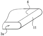
As shown in fig. 7, in embodiment 4, the end portions 11 in the length direction of the lead terminals 3a are formed in a stepped shape. More specifically, the end 11 in the longitudinal direction of the straight portion 6 of the lead terminal 3a is formed in a one-step shape having a shorter length in the longitudinal direction in the lower portion than in the upper portion.
By providing the longitudinal end portions 11 of the straight portions 6 of the lead terminals 3a in a stepped shape, stress concentrated at the corners of the longitudinal end portions of the lead terminals 3a can be dispersed to the corners of the stepped end portions 11, and stress generated in the encapsulating resin 5 can be reduced.
As described above, in the semiconductor device according to embodiment 4, since the end portions 11 in the longitudinal direction of the lead terminals 3a are formed in a stepped shape, it is possible to alleviate stress generated in the encapsulating resin 5 due to stress concentrated at the corner portions of the end portions in the longitudinal direction of the lead terminals 3 a. Further, by providing the end portions 11 in the longitudinal direction of the straight portions 6 of the lead terminals 3a in a stepped shape, a predetermined resin thickness can be secured at the end portions 11 of the lead terminals 3a, and therefore, the resin strength of the encapsulating resin 5 can be increased, and resin fluidity to the end portions 11 of the lead terminals 3a can be secured at the time of resin encapsulation.
In fig. 7, the one-step shape is illustrated, but a plurality of layers may be used. As shown in fig. 8, the end 11 of the straight portion 6 of the lead terminal 3a in the longitudinal direction may be formed in an arc shape, or as shown in fig. 9, may be formed in a chamfered shape. Here, fig. 8 is a partial oblique view of lead terminals 3a of the semiconductor device according to modification 1 of embodiment 4, and fig. 9 is a partial oblique view of lead terminals 3a of the semiconductor device according to modification 2 of embodiment 4. The same effects as described above can be obtained in the above case.
< embodiment 5>
Next, a semiconductor device according to embodiment 5 will be described. Fig. 10 is a partial plan view of the semiconductor device according to embodiment 5, and fig. 11 is a partial sectional view of the semiconductor device according to embodiment 5. In embodiment 5, the same components as those described in embodiments 1 to 4 are denoted by the same reference numerals, and description thereof is omitted.
As shown in fig. 10, in embodiment 5, lead terminals 3a are formed so as to cover the entire upper surface of semiconductor element 1 except for wire bonding pads 13, which are portions connected to signal wiring 12. More specifically, in embodiment 5, the lead terminals 3a are formed so as to have a larger profile in a plan view than in the case of embodiments 1 to 4. In addition, a concave portion 7c is provided in the lead terminal 3a at a position corresponding to the wire bonding pad 13 so as to expose the wire bonding pad 13.
As shown in fig. 10, by covering the upper surface of the semiconductor element 1 with the lead terminals 3a, stress is applied to the encapsulating resin 5 from the end portions of the lead terminals 3a due to thermal expansion of the lead terminals 3 a. As shown in fig. 11, even if a crack 8 is generated, propagation to the semiconductor element 1 can be avoided. In addition, since the recessed portion 7c is provided at a position of the lead terminal 3a corresponding to the wire bonding pad 13 in order to expose only the wire bonding pad 13, the straight portion 6 of the lead terminal 3a can be partially further cut in the horizontal direction.
As described above, in the semiconductor device according to embodiment 5, since the lead terminals 3a are formed so as to cover the entire upper surface of the semiconductor element 1 except for the portions connected to the signal wires 12, even when the cracks 8 are generated in the encapsulating resin 5 due to the stress caused by the thermal expansion of the lead terminals 3a, the cracks 8 can be prevented from being deepened on the upper surface side of the semiconductor element 1 by the lead terminals 3a, and damage to the semiconductor element 1 can be prevented. In addition, by making the lead terminals 3a large as compared with the cases of embodiments 1 to 4, the current density can be reduced, the amount of heat generation of the lead terminals 3a can be reduced, and the influence due to thermal expansion can be reduced.
< embodiment 6>
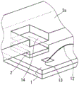
Next, a semiconductor device according to embodiment 6 will be described. Fig. 12 is a partial plan view of the semiconductor device according to embodiment 6, and fig. 13 is a partial perspective view showing a structure of lead terminals 3a of the semiconductor device according to embodiment 6. In embodiment 6, the same components as those described in embodiments 1 to 5 are denoted by the same reference numerals, and description thereof is omitted.
As shown in fig. 12 and 13, in embodiment 6, the lead terminal 3a further has a recessed portion 14, and the recessed portion 14 is provided so as to be recessed stepwise toward the upper surface side adjacent to the portion (the portion where the wire bonding pad 13 exists) to which the signal wiring 12 is connected, among the upper surface of the semiconductor element 1. More specifically, the recessed portion 14 is provided so as to be recessed in a stepwise manner at a position adjacent to the recessed portion 7c, which is a portion of the lead terminal 3a where the wire bonding pad 13 is exposed.
In fig. 13, the lead terminal 3a is formed with the recessed portion 14 by only recessing the flat surface portion to be the recessed portion 14, but a stepped recessed portion 14 may be formed by half-cutting (half-cut) as shown in fig. 14. Here, fig. 14 is a partial oblique view showing the structure of the lead terminals 3a of the semiconductor device according to the modification of embodiment 6. In fig. 13 and 14, portions of lead terminal 3a on the side of concave portion 7c from concave portion 14 are omitted for easy illustration of the drawings, and are not shown.
Next, the operation and effect of the semiconductor device according to embodiment 6 will be described. Fig. 15 is a partial plan view showing a state where a bonding operation is performed in the semiconductor device according to embodiment 6, fig. 16 is a partial cross-sectional view showing a state where a bonding operation is performed in the semiconductor device according to embodiment 6, and fig. 17 is a partial cross-sectional view showing a state where a bonding operation is performed in a case where the recess portion 14 is not provided in the semiconductor device according to embodiment 6.
As shown in fig. 15 and 16, in a state where the bonding operation by the wedge tool 16 is performed, since the side portion of the wedge tool 16 is positioned in the stepped recess portion 14 provided in the lead terminal 3a, interference between the lead terminal 3a and the wedge tool 16 can be avoided.
On the other hand, as shown in fig. 17, in the case where the recessed portions 14 are not provided in the lead terminals 3a, the relationship of the distance from the side surfaces of the lead terminals 3a to the wire bonding pads 13 is c < d. That is, it means that the wedge tool 16 interferes with the lead terminal 3a in the same positional relationship as in the case where the recess 14 is provided. Here, c is a distance from the side surface of the lead terminal 3a to the wire bonding pad 13 in the case where the recessed portion 14 is provided, and d is a distance from the side surface of the lead terminal 3a to the wire bonding pad 13 in the case where the recessed portion 14 is not provided.
Since the recessed portions 14 are provided in the lead terminals 3a, interference between the lead terminals 3a and the wedge tool 16 can be avoided, the recessed portions 7c can be minimized, and the area of the semiconductor element 1 covered with the lead terminals 3a can be increased. Further, the straight portions 6 of the lead terminals 3a can be partially cut off by the recessed portions 14, and propagation of stress generated in the encapsulating resin 5 can be suppressed.
As described above, in the semiconductor device according to embodiment 6, the lead terminal 3a further includes the recessed portion 14, and the recessed portion 14 is provided so as to be recessed stepwise toward the upper surface side adjacent to the portion of the upper surface of the semiconductor element 1 to which the signal wiring 12 is connected. Therefore, the recess 7c can be minimized in size. Further, when the recessed portion 14 is half-cut, the entire lead terminal 3a can be separated from the insulating substrate 4a, and therefore, the resin fluidity can be ensured by widening the gap between the lead terminal 3a and the insulating substrate 4 a.
< embodiment 7>
Next, a semiconductor device according to embodiment 7 will be described. Fig. 18 is a partial oblique view of the semiconductor device according to embodiment 7, and fig. 19 is a partial cross-sectional view showing the semiconductor device according to embodiment 7. In embodiment 7, the same components as those described in embodiments 1 to 6 are denoted by the same reference numerals, and description thereof is omitted.
As shown in fig. 18, in embodiment 7, the side surfaces of the portions of lead terminals 3a connected to semiconductor element 1 are subjected to surface treatment for improving wettability of solder 2. This surface treatment is, for example, Ni plating treatment, and a Ni thin film 17 is formed on a side surface of a portion of lead terminal 3a connected to semiconductor element 1. Here, the surface treatment may be Au plating, Ag plating, flux plating, or the like, in addition to Ni plating. The surface treatment may be a surface modification treatment such as chemical polishing.
As shown in fig. 19, by increasing wettability of the side surfaces of the portions of lead terminals 3a connected to semiconductor element 1, solder 2 for bonding semiconductor element 1 is wetted and ascended to the side surfaces. Since the solder 2 has low adhesiveness to the encapsulating resin 5, the interface 18 is formed between the solder 2 and the encapsulating resin 5, and thus the stress generated in the encapsulating resin 5 can be dispersed.
As described above, in the semiconductor device according to embodiment 7, since the side surfaces of the portions of lead terminals 3a connected to semiconductor element 1 are subjected to surface treatment for improving wettability, solder 2 for bonding semiconductor element 1 is wetted and climbed up to the side surfaces, and adhesiveness between the side surfaces of lead terminals 3a and encapsulating resin 5 is lowered. This can isolate the displacement of the lead terminal 3a caused by thermal expansion from the encapsulating resin 5, thereby reducing stress generated in the encapsulating resin 5.
< embodiment 8>
Next, a semiconductor device according to embodiment 8 will be described. Fig. 20 is a partial cross-sectional view of a semiconductor device according to embodiment 8. In embodiment 8, the same components as those described in embodiments 1 to 7 are denoted by the same reference numerals, and description thereof is omitted.
As shown in fig. 20, in embodiment 8, the semiconductor device further includes a terminal cover 19, and the terminal cover 19 covers a side surface of a portion of the lead terminal 3a connected to the semiconductor element 1. More specifically, the terminal cover 19 is formed in a U shape by Teflon (registered trademark) resin, and is attached to a side portion of the lead terminal 3a including a side surface of a portion connected to the semiconductor element 1. Here, the terminal cover 19 may be made of a thermoplastic resin such as ABS, PC, PS, or PPS, or a metal material such as SUS304, in addition to a Teflon (registered trademark) resin.
By mounting the terminal cover 19 on the side of the lead terminal 3a and then filling the encapsulating resin 5, the displacement of the thermal expansion or contraction of the lead terminal 3a can be isolated from the encapsulating resin 5. Therefore, the stress transmitted to the sealing resin 5 can be minimized. This provides an effect of suppressing the generation of cracks 8 in the sealing resin 5. In addition, a semiconductor device mainly composed of silicon carbide can operate at a higher temperature. That is, since the sealing resin 5 can be in a good sealing state, a semiconductor device with more excellent reliability can be provided.
As described above, the semiconductor device according to embodiment 8 further includes the terminal cover 19, and the terminal cover 19 covers the side surfaces of the portions of the lead terminals 3a connected to the semiconductor element 1, and therefore, the interfaces are intentionally formed between the lead terminals 3a and the encapsulating resin 5, and the stress applied to the encapsulating resin 5 can be reduced.
In addition, the present invention can be freely combined with each embodiment or appropriately modified or omitted from each embodiment within the scope of the invention.
Claims (16)
1. A semiconductor device, comprising:
a semiconductor element having a lower surface bonded to the substrate side;
a lead terminal bonded to an upper surface of the semiconductor element, wherein a longitudinal end of the lead terminal is formed in a stepped shape having a shorter longitudinal length in a lower portion than in an upper portion; and
an encapsulating resin encapsulating the semiconductor element together with the step-shaped portion of the lead terminal,
the lead terminals are formed so as to cover the entire upper surface of the semiconductor element except for portions connected to signal wirings.
2. A semiconductor device, comprising:
a semiconductor element having a lower surface bonded to the substrate side;
a lead terminal bonded to an upper surface of the semiconductor element, wherein a longitudinal end of the lead terminal is formed in a stepped shape having a shorter longitudinal length in a lower portion than in an upper portion; and
an encapsulating resin encapsulating the semiconductor element together with the step-shaped portion of the lead terminal,
the lead terminals have portions extending in a horizontal direction,
the portions of the lead terminals extending in the horizontal direction include portions joined to the semiconductor element and extending linearly in a plan view,
the lead terminal has a concave portion or a convex portion which partially breaks the linearly extended portion in a plan view,
the lead terminals are formed so as to cover the entire upper surface of the semiconductor element except for portions connected to signal wirings.
3. A semiconductor device, comprising:
a semiconductor element having a lower surface bonded to the substrate side;
lead terminals bonded to the upper surface of the semiconductor element, the lead terminals having end portions in the longitudinal direction formed in a multi-step shape having a shorter length in the longitudinal direction in lower portions than in upper portions; and
an encapsulating resin encapsulating the semiconductor element together with the multi-layered step-shaped portion of the lead terminal,
the lead terminals are formed so as to cover the entire upper surface of the semiconductor element except for portions connected to signal wirings.
4. A semiconductor device, comprising:
a semiconductor element having a lower surface bonded to the substrate side;
a lead terminal bonded to an upper surface of the semiconductor element, a shape of a longitudinal end of the lead terminal being formed in an arc shape; and
an encapsulating resin encapsulating the semiconductor element together with the circular-arc shaped portions of the lead terminals,
the lead terminals are formed so as to cover the entire upper surface of the semiconductor element except for portions connected to signal wirings.
5. A semiconductor device, comprising:
a semiconductor element having a lower surface bonded to the substrate side;
a lead terminal bonded to an upper surface of the semiconductor element, a shape of a longitudinal end of the lead terminal being formed in a chamfered shape; and
an encapsulating resin encapsulating the semiconductor element together with the chamfered shape portions of the lead terminals,
the lead terminals are formed so as to cover the entire upper surface of the semiconductor element except for portions connected to signal wirings.
6. The semiconductor device according to any one of claims 1 to 5,
the linear expansion coefficient of the encapsulating resin is an intermediate value between the linear expansion coefficient of the lead terminal and the linear expansion coefficient of the semiconductor element.
7. The semiconductor device according to claim 2,
the concave portion or the convex portion is configured to have a width and a depth larger than or equal to a thickness of the lead terminal.
8. The semiconductor device according to claim 2 or 7,
the lead terminal further includes a slit formed so that a width of a portion of the lead terminal continuous with the concave portion or the convex portion is larger than or equal to a thickness of the lead terminal.
9. The semiconductor device according to any one of claims 2 and 7,
the lead terminal further has a bent portion bent upward at a portion corresponding to the concave portion or the convex portion.
10. A semiconductor device, comprising:
a semiconductor element having a lower surface bonded to the substrate side;
lead terminals bonded to an upper surface of the semiconductor element; and
an encapsulating resin encapsulating the semiconductor element together with a portion of the lead terminal bonded to the semiconductor element,
the linear expansion coefficient of the encapsulating resin is an intermediate value between the linear expansion coefficient of the lead terminal and the linear expansion coefficient of the semiconductor element,
the lead terminals are formed so as to cover the entire upper surface of the semiconductor element except for portions connected to signal wirings,
the lead terminal further has a recessed portion provided in a stepped recess toward the upper surface side adjacent to a portion to which a signal wiring is connected, of the upper surface of the semiconductor element.
11. A semiconductor device, comprising:
a semiconductor element having a lower surface bonded to the substrate side;
a lead terminal bonded to an upper surface of the semiconductor element, wherein a longitudinal end of the lead terminal is formed in a stepped shape having a shorter longitudinal length in a lower portion than in an upper portion; and
an encapsulating resin encapsulating the semiconductor element together with the step-shaped portion of the lead terminal,
the lead terminals are formed so as to cover the entire upper surface of the semiconductor element except for portions connected to signal wirings,
the lead terminal further has a recessed portion provided in a stepped recess toward the upper surface side adjacent to a portion to which a signal wiring is connected, of the upper surface of the semiconductor element.
12. The semiconductor device according to any one of claims 1 to 5, 10 and 11,
a side surface of a portion of the lead terminal connected to the semiconductor element is subjected to a surface treatment for improving wettability.
13. A semiconductor device, comprising:
a semiconductor element having a lower surface bonded to the substrate side;
lead terminals bonded to an upper surface of the semiconductor element; and
an encapsulating resin encapsulating the semiconductor element together with a portion of the lead terminal bonded to the semiconductor element,
the linear expansion coefficient of the encapsulating resin is an intermediate value between the linear expansion coefficient of the lead terminal and the linear expansion coefficient of the semiconductor element,
there is also a terminal cover covering a side surface of a portion of the lead terminal connected to the semiconductor element.
14. A semiconductor device, comprising:
a semiconductor element having a lower surface bonded to the substrate side;
a lead terminal bonded to an upper surface of the semiconductor element, wherein a longitudinal end of the lead terminal is formed in a stepped shape having a shorter longitudinal length in a lower portion than in an upper portion; and
an encapsulating resin encapsulating the semiconductor element together with the step-shaped portion of the lead terminal,
there is also a terminal cover covering a side surface of a portion of the lead terminal connected to the semiconductor element.
15. The semiconductor device according to any one of claims 1 to 5, 10, 11, 13, and 14,
the semiconductor element is a wide bandgap semiconductor element.
16. The semiconductor device according to any one of claims 1 to 5, 10, 11, 13, and 14,
the semiconductor device is a power semiconductor device used in an inverter or a regenerative converter for controlling a motor of a vehicle.
Applications Claiming Priority (3)
| Application Number | Priority Date | Filing Date | Title |
|---|---|---|---|
| JP2014211424A JP6385234B2 (en) | 2014-10-16 | 2014-10-16 | Semiconductor device |
| JP2014-211424 | 2014-10-16 | ||
| CN201510673980.6A CN105529319B (en) | 2014-10-16 | 2015-10-16 | Semiconductor device |
Related Parent Applications (1)
| Application Number | Title | Priority Date | Filing Date |
|---|---|---|---|
| CN201510673980.6A Division CN105529319B (en) | 2014-10-16 | 2015-10-16 | Semiconductor device |
Publications (2)
| Publication Number | Publication Date |
|---|---|
| CN106952877A CN106952877A (en) | 2017-07-14 |
| CN106952877B true CN106952877B (en) | 2021-01-01 |
Family
ID=55638195
Family Applications (3)
| Application Number | Title | Priority Date | Filing Date |
|---|---|---|---|
| CN201910281594.0A Active CN110071072B (en) | 2014-10-16 | 2015-10-16 | Semiconductor device with a semiconductor device having a plurality of semiconductor chips |
| CN201611055874.2A Active CN106952877B (en) | 2014-10-16 | 2015-10-16 | Semiconductor device with a plurality of semiconductor chips |
| CN201510673980.6A Active CN105529319B (en) | 2014-10-16 | 2015-10-16 | Semiconductor device |
Family Applications Before (1)
| Application Number | Title | Priority Date | Filing Date |
|---|---|---|---|
| CN201910281594.0A Active CN110071072B (en) | 2014-10-16 | 2015-10-16 | Semiconductor device with a semiconductor device having a plurality of semiconductor chips |
Family Applications After (1)
| Application Number | Title | Priority Date | Filing Date |
|---|---|---|---|
| CN201510673980.6A Active CN105529319B (en) | 2014-10-16 | 2015-10-16 | Semiconductor device |
Country Status (4)
| Country | Link |
|---|---|
| US (1) | US9917064B2 (en) |
| JP (1) | JP6385234B2 (en) |
| CN (3) | CN110071072B (en) |
| DE (1) | DE102015215786A1 (en) |
Families Citing this family (10)
| Publication number | Priority date | Publication date | Assignee | Title |
|---|---|---|---|---|
| US10204847B2 (en) * | 2016-10-06 | 2019-02-12 | Infineon Technologies Americas Corp. | Multi-phase common contact package |
| CN109952639B (en) | 2016-11-11 | 2023-06-27 | 三菱电机株式会社 | Semiconductor device, inverter unit, and automobile |
| JP6776840B2 (en) * | 2016-11-21 | 2020-10-28 | オムロン株式会社 | Electronic devices and their manufacturing methods |
| CN110249426B (en) * | 2017-02-09 | 2023-10-17 | 三菱电机株式会社 | Semiconductor device and power conversion device |
| US10896868B2 (en) * | 2017-02-20 | 2021-01-19 | Shindengen Electric Manufacturing Co., Ltd. | Electronic device and connector |
| US11257768B2 (en) * | 2017-12-13 | 2022-02-22 | Mitsubishi Electric Corporation | Semiconductor device and power conversion device |
| EP3832705A4 (en) * | 2018-11-30 | 2021-09-15 | Hitachi Metals, Ltd. | Electrical connection member, electrical connection structure, and method for producing electrical connection member |
| US11387210B2 (en) * | 2019-03-15 | 2022-07-12 | Fuji Electric Co., Ltd. | Semiconductor module and manufacturing method therefor |
| JP7301805B2 (en) * | 2020-09-24 | 2023-07-03 | 株式会社東芝 | semiconductor module |
| WO2023203688A1 (en) * | 2022-04-20 | 2023-10-26 | 三菱電機株式会社 | Semiconductor device and production method for semiconductor device |
Citations (7)
| Publication number | Priority date | Publication date | Assignee | Title |
|---|---|---|---|---|
| CN1988137A (en) * | 2005-12-19 | 2007-06-27 | 三菱电机株式会社 | Semiconductor device |
| JP2007173703A (en) * | 2005-12-26 | 2007-07-05 | Mitsubishi Electric Corp | Semiconductor device |
| JP2010147053A (en) * | 2008-12-16 | 2010-07-01 | Fuji Electric Systems Co Ltd | Semiconductor device |
| CN102593091A (en) * | 2011-01-14 | 2012-07-18 | 丰田自动车株式会社 | Semiconductor module |
| CN103545268A (en) * | 2012-07-09 | 2014-01-29 | 万国半导体股份有限公司 | Power device with bottom source electrode and preparation method |
| CN103843135A (en) * | 2011-09-29 | 2014-06-04 | 丰田自动车株式会社 | Semiconductor device |
| CN103972276A (en) * | 2013-02-06 | 2014-08-06 | 三菱电机株式会社 | Semiconductor device and method of manufacturing the same |
Family Cites Families (17)
| Publication number | Priority date | Publication date | Assignee | Title |
|---|---|---|---|---|
| JPH01276655A (en) | 1988-04-27 | 1989-11-07 | Japan Radio Co Ltd | Transfer mold type integrated circuit |
| JPH065742A (en) | 1992-06-22 | 1994-01-14 | Mitsubishi Electric Corp | Semiconductor device, resin used used for sealing and manufacture of the device |
| JPH06120406A (en) | 1992-10-02 | 1994-04-28 | Mitsubishi Electric Corp | Semiconductor device |
| JP3866880B2 (en) | 1999-06-28 | 2007-01-10 | 株式会社日立製作所 | Resin-sealed electronic device |
| JP2005012085A (en) * | 2003-06-20 | 2005-01-13 | Toyota Motor Corp | Electrode structure of semiconductor module |
| JP4628687B2 (en) * | 2004-03-09 | 2011-02-09 | ルネサスエレクトロニクス株式会社 | Semiconductor device |
| JP4468115B2 (en) * | 2004-08-30 | 2010-05-26 | 株式会社ルネサステクノロジ | Semiconductor device |
| CN100442483C (en) | 2004-09-16 | 2008-12-10 | 夏普株式会社 | Optical semiconductor device, method for fabricating the same, lead frame and electronic equipment |
| DE102005043928B4 (en) * | 2004-09-16 | 2011-08-18 | Sharp Kk | Optical semiconductor device and method for its production |
| TWI280673B (en) * | 2004-09-22 | 2007-05-01 | Sharp Kk | Optical semiconductor device, optical communication device, and electronic equipment |
| JP4348267B2 (en) | 2004-09-22 | 2009-10-21 | シャープ株式会社 | Optical semiconductor device, optical communication device, and electronic equipment |
| JP4492448B2 (en) | 2005-06-15 | 2010-06-30 | 株式会社日立製作所 | Semiconductor power module |
| JP2008016529A (en) * | 2006-07-04 | 2008-01-24 | Renesas Technology Corp | Semiconductor device |
| JP2008218688A (en) * | 2007-03-05 | 2008-09-18 | Denso Corp | Semiconductor device |
| JP5384913B2 (en) * | 2008-11-18 | 2014-01-08 | ルネサスエレクトロニクス株式会社 | Semiconductor device and manufacturing method thereof |
| JP5665572B2 (en) | 2011-01-28 | 2015-02-04 | 三菱電機株式会社 | Semiconductor device and manufacturing method of semiconductor device |
| JP2013197573A (en) | 2012-03-23 | 2013-09-30 | Mitsubishi Electric Corp | Semiconductor device |
-
2014
- 2014-10-16 JP JP2014211424A patent/JP6385234B2/en active Active
-
2015
- 2015-07-02 US US14/790,682 patent/US9917064B2/en active Active
- 2015-08-19 DE DE102015215786.5A patent/DE102015215786A1/en active Pending
- 2015-10-16 CN CN201910281594.0A patent/CN110071072B/en active Active
- 2015-10-16 CN CN201611055874.2A patent/CN106952877B/en active Active
- 2015-10-16 CN CN201510673980.6A patent/CN105529319B/en active Active
Patent Citations (7)
| Publication number | Priority date | Publication date | Assignee | Title |
|---|---|---|---|---|
| CN1988137A (en) * | 2005-12-19 | 2007-06-27 | 三菱电机株式会社 | Semiconductor device |
| JP2007173703A (en) * | 2005-12-26 | 2007-07-05 | Mitsubishi Electric Corp | Semiconductor device |
| JP2010147053A (en) * | 2008-12-16 | 2010-07-01 | Fuji Electric Systems Co Ltd | Semiconductor device |
| CN102593091A (en) * | 2011-01-14 | 2012-07-18 | 丰田自动车株式会社 | Semiconductor module |
| CN103843135A (en) * | 2011-09-29 | 2014-06-04 | 丰田自动车株式会社 | Semiconductor device |
| CN103545268A (en) * | 2012-07-09 | 2014-01-29 | 万国半导体股份有限公司 | Power device with bottom source electrode and preparation method |
| CN103972276A (en) * | 2013-02-06 | 2014-08-06 | 三菱电机株式会社 | Semiconductor device and method of manufacturing the same |
Also Published As
| Publication number | Publication date |
|---|---|
| CN105529319A (en) | 2016-04-27 |
| US20160111379A1 (en) | 2016-04-21 |
| CN110071072B (en) | 2023-12-01 |
| CN106952877A (en) | 2017-07-14 |
| JP6385234B2 (en) | 2018-09-05 |
| DE102015215786A1 (en) | 2016-04-21 |
| US9917064B2 (en) | 2018-03-13 |
| CN105529319B (en) | 2019-04-26 |
| JP2016082048A (en) | 2016-05-16 |
| CN110071072A (en) | 2019-07-30 |
Similar Documents
| Publication | Publication Date | Title |
|---|---|---|
| CN106952877B (en) | Semiconductor device with a plurality of semiconductor chips | |
| JP6234630B2 (en) | Power module | |
| US9153519B2 (en) | Semiconductor device for preventing a progression of a crack in a solder layer and method of manufacturing the same | |
| JP6293030B2 (en) | Power semiconductor device | |
| JP6316412B2 (en) | Power semiconductor device | |
| US20160300770A1 (en) | Power module and method of manufacturing power module | |
| US10763240B2 (en) | Semiconductor device comprising signal terminals extending from encapsulant | |
| EP2717310A1 (en) | Semiconductor device and wiring substrate | |
| JP2016018866A (en) | Power module | |
| JP4530863B2 (en) | Resin-sealed semiconductor device | |
| WO2021002132A1 (en) | Semiconductor module circuit structure | |
| JP2015115471A (en) | Power semiconductor device | |
| JP2008016469A (en) | Semiconductor device | |
| JP5368357B2 (en) | Electrode member and semiconductor device using the same | |
| CN110892526B (en) | Method for manufacturing semiconductor device | |
| WO2015125772A1 (en) | Electrode lead and semiconductor device | |
| US11302612B2 (en) | Lead frame wiring structure and semiconductor module | |
| KR101561920B1 (en) | Semiconductor package | |
| US11823985B2 (en) | Leadframe, semiconductor device, and method for manufacturing semiconductor device | |
| US11646250B2 (en) | Semiconductor device | |
| WO2022070741A1 (en) | Semiconductor device | |
| JP6416055B2 (en) | Semiconductor device | |
| CN110892527A (en) | Semiconductor device and method for manufacturing semiconductor device | |
| CN111316429A (en) | Semiconductor device with a plurality of semiconductor chips | |
| JP2015167171A (en) | semiconductor device |
Legal Events
| Date | Code | Title | Description |
|---|---|---|---|
| PB01 | Publication | ||
| PB01 | Publication | ||
| SE01 | Entry into force of request for substantive examination | ||
| SE01 | Entry into force of request for substantive examination | ||
| GR01 | Patent grant | ||
| GR01 | Patent grant |