CN106828517B - Split type electric rail car - Google Patents
Split type electric rail car Download PDFInfo
- Publication number
- CN106828517B CN106828517B CN201710151396.3A CN201710151396A CN106828517B CN 106828517 B CN106828517 B CN 106828517B CN 201710151396 A CN201710151396 A CN 201710151396A CN 106828517 B CN106828517 B CN 106828517B
- Authority
- CN
- China
- Prior art keywords
- chassis
- control system
- carriage body
- split type
- rail car
- Prior art date
- Legal status (The legal status is an assumption and is not a legal conclusion. Google has not performed a legal analysis and makes no representation as to the accuracy of the status listed.)
- Expired - Fee Related
Links
- 239000006096 absorbing agent Substances 0.000 claims description 3
- 238000000034 method Methods 0.000 claims description 3
- 230000035939 shock Effects 0.000 claims description 3
- 206010063385 Intellectualisation Diseases 0.000 abstract description 2
- 230000009286 beneficial effect Effects 0.000 abstract description 2
- 238000003915 air pollution Methods 0.000 description 2
- 230000008054 signal transmission Effects 0.000 description 2
- 230000007547 defect Effects 0.000 description 1
- 230000007613 environmental effect Effects 0.000 description 1
- 239000003344 environmental pollutant Substances 0.000 description 1
- 231100000719 pollutant Toxicity 0.000 description 1
- 230000026676 system process Effects 0.000 description 1
Images
Classifications
-
- B—PERFORMING OPERATIONS; TRANSPORTING
- B61—RAILWAYS
- B61D—BODY DETAILS OR KINDS OF RAILWAY VEHICLES
- B61D13/00—Tramway vehicles
Landscapes
- Engineering & Computer Science (AREA)
- Transportation (AREA)
- Mechanical Engineering (AREA)
- Electric Propulsion And Braking For Vehicles (AREA)
Abstract
The split type electric rail car is a new vehicle, the chassis and the carriage body of the electric rail car are designed into relatively independent split type structures, and the chassis and the carriage body can be separated and combined, so that the carriage body can be moved to a special platform when the rail car stops, and the carriage body can be moved to the chassis of a front car when a rear car needs to pass, so that the front car stops without influencing the passing of the rear car; the rail transit vehicle control system is beneficial to realizing miniaturization and intellectualization of the rail transit vehicle. The vehicle runs on a special track, the passing efficiency is high, and unmanned driving can be realized.
Description
Technical Field
The invention relates to a vehicle, in particular to a split type electric rail car.
Background
With the development of society, automobiles enter common families, but the number of automobiles is increased day by day, frequent congestion occurs on many urban roads, inconvenience is brought to people going out, and meanwhile, the air pollution condition is also increased day by day due to the fact that the number of automobiles is increased continuously.
The rail transit can solve the problem of air pollution and road congestion well, but the carriage body and the chassis of all rail cars are all integrative at present, must let each rail transit car possess a track just can not influence the vehicle and pass when berthing, so lead to rail car can only be as large-scale public transport, and the convenience is far away not like the car.
Disclosure of Invention
Aiming at the defects of the transportation tools, the chassis and the carriage body of the rail car are designed in a split mode, so that the chassis is shared by the cars, and the carriage body can be separated from the chassis, so that the rail transportation tools are convenient and fast; meanwhile, information interconnection and intercommunication among vehicles are realized by utilizing a sensor and a control system on the rail car, so that the unmanned split type electric rail car is realized.
The purpose of the invention is realized by the following scheme:
the split type electric rail car consists of a chassis and a carriage body, wheels, a braking system, a power system, a shock absorber, electric power storage equipment, a sensor, a control system and the like are arranged on the chassis, the electric power storage equipment, the control system, the sensor and the like are arranged in the carriage body, the chassis and the carriage body of the electric rail car are of relatively independent split type structures, and the chassis and the carriage body are automatically separated or combined under the instruction of the control system.
The upper part of a chassis of the rail car is provided with a guide rail groove and a liftable driving roller, the driving roller is driven by a driving motor and can rotate forwards or backwards according to instructions, the driving roller is provided with a transverse driving roller and a longitudinal driving roller, and the lower part of a carriage body is provided with a guide rail.
The wheels on two sides of the chassis are respectively driven by independent driving devices, and the wheels are provided with single-side wheel rims and can run on the track.
After the chassis is combined with the carriage body, the two electric power storage devices are in a parallel state, the chassis is provided with a telescopic power receiving rod, and the electric power storage devices can be charged through the power receiving rod.
The sensors are arranged on the front, rear, left, right and upper parts of the chassis of the split type electric rail car and the lower part of the car body.
A stop station is arranged at intervals on the track line of the split type electric railcar, and a guide rail groove, a liftable driving roller, a sensor and a control system are arranged on the stop station platform.
The control system of the split type electric railcar is responsible for exchanging information with the outside and adjusting the running state of the vehicle, when the vehicle enters the station, the control system of the station and the control system of the vehicle are interconnected and intercommunicated through a wireless network, and after the chassis is combined with the carriage body, the control system of the chassis and the control system of the carriage body are interconnected and intercommunicated.
The control system processes signals transmitted by the sensors and automatically controls the advancing, separating and combining of the vehicle.
Split type electric rail car compares with current rail vehicle and has the advantage: the carriage body can be moved to a special platform when the rail vehicle stops, and the carriage body can be moved to a chassis of a front vehicle when a rear vehicle needs to pass, so that the front vehicle stops without influencing the passing of the rear vehicle; and is beneficial to realizing miniaturization and intellectualization of the rail transit vehicle.
Compared with the prior common road vehicle, the split type electric rail car has the advantages that: the vehicle has the advantages of no pollutant discharge, environmental protection, running on a special track, high traffic efficiency and capability of realizing unmanned driving.
Drawings
Fig. 1 is a schematic perspective view of a chassis of a railway vehicle.
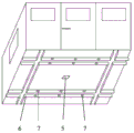
Fig. 2 is a schematic perspective view of a railway car carriage body.
Detailed Description
As shown in fig. 1 and fig. 2, the split type electric rail car is composed of a chassis and a carriage body, wherein the chassis is provided with a guide rail groove 1, a lifting longitudinal driving roller 2, a lifting transverse driving roller 3, a telescopic power receiving rod 4, a sensor 5, wheels 8, a brake, a power system, a shock absorber, a locking device, an electric power storage device, a control system and the like; the carriage body is provided with an electric storage device, a control system, a sensor 5 and a guide rail 6, the guide rail 6 is provided with a locking hole 7, and a vehicle needs to run on a track 9.
When the vehicle is about to reach the designated position and needs to stop, the chassis sensor 5 transmits a signal to the control system, the control system gives a speed reduction and stop instruction to the brake system, the chassis unlocks the carriage body, the transverse driving roller 3 lifts the carriage body guide rail 6 to enable the guide rail 6 on the carriage body to lift away from the guide rail groove 1 on the chassis, then the carriage body moves towards the platform, the transverse driving roller 3 on the platform also lifts and moves the carriage body towards the platform, when the carriage body moves to the designated position, the sensor 5 transmits the signal to the control system, the transverse driving roller 3 stops moving and simultaneously starts to descend, and the guide rail 6 on the carriage body is placed in the guide rail groove 1 on the platform.
The control system of the split type electric rail car can realize man-machine conversation with passengers through the terminal, the requirements of the passengers are transmitted to the rail traffic control center, the rail traffic control center calculates and sends the optimal driving route according to the rail traffic conditions, and the split type electric rail car automatically runs to the destination after receiving the driving route. In the driving process, the vehicle determines the driving state through the sensing device 5 and the control system, and exchanges data with the rail transit control center in real time through a wireless network.
When the rear car will pass through, when being close to the front car chassis, chassis sensor 5 gives control system with the signal transmission, control system assigns speed reduction and parking instruction to braking system, the locking to the carriage body is relieved to the rear car chassis, longitudinal drive gyro wheel 2 rises simultaneously on two front and back chassis, then move the rear car carriage body to the front car chassis, when the carriage body reachs the assigned position, sensor 5 gives control system with the signal transmission, longitudinal drive gyro wheel 2 stop motion, begin to descend simultaneously, place guide rail 6 on the rear car carriage body to the guide rail groove 1 of front car in, locking device on the chassis inserts locking hole 7, the vehicle begins to operate.
In the running process of the vehicle, the power receiving rod 4 extends out to contact with a power supply contact net, so that power supply is provided for the vehicle, and meanwhile, the power storage equipment on the vehicle is charged; when the vehicle enters the stop station, the power receiving rod 4 is disconnected from the power supply contact network, and the vehicle is supplied with power by the power storage equipment.
Claims (7)
1. The utility model provides an unmanned split type electric rail car, comprises chassis, the carriage body, has wheel, braking system, driving system, shock absorber, electrical storage equipment, sensor, control system on the chassis, has electrical storage equipment, control system, sensor in the carriage body, its characterized in that: the chassis and the carriage body of the electric rail car are of relatively independent split structures, the chassis control system and the carriage body control system can exchange information with the outside, the lower part of the carriage body and the upper part of the chassis of the rail car are provided with split devices consisting of guide rails, guide rail grooves and liftable driving rollers, the driving rollers are provided with transverse driving rollers and longitudinal driving rollers, the driving rollers are driven by driving motors and can rotate forwards or backwards according to instructions, manual operation is not needed under the instructions of the control system, the carriage body can be automatically moved to other chassis or platforms in the front, back, left and right directions from one chassis under the action of the split devices.
2. The split type electric rail car of claim 1, characterized in that: the wheels on two sides of the chassis are respectively driven by independent power devices, and the wheels are provided with single-side wheel rims and run on the track.
3. The split type electric rail car of claim 1, characterized in that: after the chassis is combined with the carriage body, the two electric power storage devices are in a parallel state, the chassis is provided with a telescopic power receiving rod, and the electric power storage devices are charged through the power receiving rod.
4. The split type electric rail car of claim 1, characterized in that: the front, back, left, right and upper parts of the chassis and the lower part of the carriage body are all provided with sensors.
5. The split type electric rail car of claim 1, characterized in that: a stop station is arranged at intervals on the track line of the split type electric railcar, and a guide rail groove, a liftable driving roller, a sensor and a control system are arranged on the stop station platform.
6. The split type electric rail car of claim 1, characterized in that: the control system of the split type electric railcar is responsible for exchanging information with the outside and adjusting the running state of the vehicle, when the vehicle enters the station, the control system of the station and the control system of the vehicle are interconnected and intercommunicated through a wireless network, and after the chassis is combined with the carriage body, the control system of the chassis and the control system of the carriage body are interconnected and intercommunicated.
7. The split type electric rail car of claim 1, characterized in that: the control system of the electric rail car processes signals transmitted by the sensors and automatically controls the advancing, separating and combining of the car.
Priority Applications (1)
| Application Number | Priority Date | Filing Date | Title |
|---|---|---|---|
| CN201710151396.3A CN106828517B (en) | 2017-03-14 | 2017-03-14 | Split type electric rail car |
Applications Claiming Priority (1)
| Application Number | Priority Date | Filing Date | Title |
|---|---|---|---|
| CN201710151396.3A CN106828517B (en) | 2017-03-14 | 2017-03-14 | Split type electric rail car |
Publications (2)
| Publication Number | Publication Date |
|---|---|
| CN106828517A CN106828517A (en) | 2017-06-13 |
| CN106828517B true CN106828517B (en) | 2020-02-07 |
Family
ID=59144564
Family Applications (1)
| Application Number | Title | Priority Date | Filing Date |
|---|---|---|---|
| CN201710151396.3A Expired - Fee Related CN106828517B (en) | 2017-03-14 | 2017-03-14 | Split type electric rail car |
Country Status (1)
| Country | Link |
|---|---|
| CN (1) | CN106828517B (en) |
Families Citing this family (3)
| Publication number | Priority date | Publication date | Assignee | Title |
|---|---|---|---|---|
| IT201800003333A1 (en) * | 2018-03-07 | 2019-09-07 | Iveco France Sas | MODULAR VEHICLE |
| CN111231687B (en) * | 2018-11-29 | 2022-05-13 | 比亚迪股份有限公司 | Charging system |
| CN114834500B (en) * | 2022-04-27 | 2024-04-26 | 交控科技股份有限公司 | Signal system cutting circuit and cutting method for carriage chassis separation |
Family Cites Families (6)
| Publication number | Priority date | Publication date | Assignee | Title |
|---|---|---|---|---|
| BE639576A (en) * | 1962-11-07 | |||
| CN85205532U (en) * | 1985-11-22 | 1988-02-10 | 古飞 | Fixing means for mounting various carriages on same chassis |
| CN2613411Y (en) * | 2003-04-25 | 2004-04-28 | 李勇 | Train and truck body with horizontal shifting slide way for container |
| CN101628583B (en) * | 2009-08-18 | 2011-03-30 | 王弘 | Novel public transportation networking system of high-speed fully-automatic fully-closed track train |
| CN104908829A (en) * | 2014-03-14 | 2015-09-16 | 都快通(北京)交通疏导设备有限公司 | Left-turn high-end city public traffic system applying movable compartments |
| CN204586616U (en) * | 2015-01-20 | 2015-08-26 | 梁迎新 | Mobile shipping railway carriage or compartment |
-
2017
- 2017-03-14 CN CN201710151396.3A patent/CN106828517B/en not_active Expired - Fee Related
Also Published As
| Publication number | Publication date |
|---|---|
| CN106828517A (en) | 2017-06-13 |
Similar Documents
| Publication | Publication Date | Title |
|---|---|---|
| CN102501858B (en) | Narrow-gauge electric motor car | |
| CN207173202U (en) | A kind of rail convertible car | |
| CN102951160A (en) | Overhead rail transit system | |
| JP2009530514A (en) | High-efficiency, energy-saving, environmentally-friendly vehicle and line and operation method | |
| CN106828517B (en) | Split type electric rail car | |
| CN101774355A (en) | Rail transportation system powered by solar energy | |
| CN102233882A (en) | Lead rail type dual-lead wheel rail transport system | |
| CN100406282C (en) | Automobile railroad | |
| CN202882492U (en) | Multilayer roadway stacker | |
| CN102501859B (en) | Power car for narrow gauge electric motor car | |
| CN102910173B (en) | A kind of track switch steering mechanism of suspension type monorail fast public traffic system | |
| CN103241246A (en) | Urban rail public traffic and transportation system | |
| JP3091587B2 (en) | Vertical and horizontal moving elevator | |
| CN113733828A (en) | Quick highway-railway road conversion system | |
| CN201573646U (en) | Overhead soft track traffic system | |
| CN205951968U (en) | Electronic urban mass transit system of single -stop -type microlight -type | |
| WO2022000439A1 (en) | Multi-track track changing system and track changing method therefor, and vehicle cpable of changing track | |
| CN202220465U (en) | Automobile shifting bench used for three-dimensional garage | |
| CN106114529A (en) | One-stop microlight-type electric urban Rail Transit System | |
| CN116654033A (en) | Self-guiding and fusion electronic guiding multi-scene operation method and system for rubber-tyred train | |
| CN212529626U (en) | Rail-mounted electrically-driven vehicle system | |
| CN102359296A (en) | Automobile moving platform for three-dimensional garage | |
| CN202439691U (en) | Urban rail public traffic transport system | |
| CN211764873U (en) | Rubber-tyred electric car and power bogie structure thereof | |
| CN101407220A (en) | Multi-track combination technology for flying in air |
Legal Events
| Date | Code | Title | Description |
|---|---|---|---|
| PB01 | Publication | ||
| PB01 | Publication | ||
| SE01 | Entry into force of request for substantive examination | ||
| SE01 | Entry into force of request for substantive examination | ||
| GR01 | Patent grant | ||
| GR01 | Patent grant | ||
| CF01 | Termination of patent right due to non-payment of annual fee |
Granted publication date: 20200207 |
|
| CF01 | Termination of patent right due to non-payment of annual fee |