Disclosure of Invention
The present invention has been made to solve at least part of the above problems, and can be realized by the following embodiments or application examples.
Application example 1a heat flow meter according to the present application example includes: a heat transfer portion having a first surface and a second surface facing each other and having flexibility; and a temperature difference measuring unit that measures a temperature difference between the first surface and the second surface of the heat transfer unit.
According to the configuration of the present application example, the heat flow meter can measure the heat flow by the heat transfer by measuring the temperature difference between the first surface and the second surface of the heat transfer portion having flexibility by the temperature difference measuring portion. For example, when the heat flow is measured by bringing the first surface of the heat transfer portion into contact with a human body (forearm) or the like, the heat transfer portion is attached to the surface of the forearm (skin surface) because of its flexibility. Therefore, the adhesion to the skin surface is improved, and an air layer is less likely to be generated between the heat transfer portion and the skin surface, thereby suppressing a decrease in the contact area. As a result, an error in measuring the heat flow generated between the skin surface in contact with the first surface and the external environment in contact with the second surface can be reduced, and thus the amount of heat dissipated from the human body can be measured with high accuracy.
Application example 2 in the heat flow meter according to the application example, the heat transfer portion preferably includes: a first member having flexibility; and a second member having a higher thermal conductivity than the first member.
According to the structure of the present application example, the heat transfer portion includes: a first member having flexibility; and a second member having a higher thermal conductivity than the first member. Therefore, the heat transfer portion can be constituted by using the flexible first member as a base material, and the second member can impart thermal conductivity.
Application example 3 in the heat flow meter according to the application example, it is preferable that the thickness of the heat transfer portion is 0.5mm or more, the thermal conductivity of the heat transfer portion is 10W/(m × K) or more, and the shore hardness of the heat transfer portion is a50 or less.
According to the structure of the present application example, since the thickness of the heat transfer portion is 0.5mm or more, a temperature difference for measuring a heat flow can be generated in the thickness direction between the first surface and the second surface. The heat transfer portion preferably has a thermal conductivity of 10W/(m × K) or more and is larger than that of general rubber, and therefore, is preferably used as a material of the heat transfer portion. Further, since the shore hardness of the heat transfer portion is not more than a50, the flexibility of the heat transfer portion can be improved.
Application example 4 in the heat flux meter according to the application example, a heat diffusion layer having a thermal conductivity of more than 100W/(m × K) is preferably disposed on the first surface.
According to the configuration of the present application example, since the heat diffusion layer having a thermal conductivity higher than that of the heat transfer portion is disposed on the first surface of the heat transfer portion, the in-plane temperature distribution of the first surface can be made more uniform. Therefore, when measuring the heat flow, the heat flow can be measured in a relatively stable state even if there is a fluctuation due to the contact state with the skin surface or a fluctuation due to the temperature distribution on the skin surface.
Application example 5 in the heat flux meter according to the application example, the shore hardness of the heat diffusion layer is preferably a50 or less.
According to the structure of the present application example, the shore hardness of the thermal diffusion layer disposed on the first surface is the same as that of the heat transfer portion, and therefore the flexibility of the heat transfer portion is not impaired.
Application example 6 in the heat flux meter according to the above application example, it is preferable that a protective layer made of an organic material is disposed on a surface of the heat diffusion layer.
According to the configuration of the present application example, since the protective layer is disposed on the surface of the heat diffusion layer, the heat diffusion layer and the heat transfer portion can be protected from contact with an external object or the like.
Application example 7 in the heat flux meter according to the application example, the shore hardness of the protective layer is preferably a50 or less.
According to the structure of the present application example, the shore hardness of the protective layer disposed on the surface of the heat diffusion layer is the same as that of the heat diffusion layer and the heat transfer portion, and therefore the flexibility of the heat transfer portion and the heat diffusion layer is not impaired.
Application example 8 the heat flow meter according to the above application example is preferably configured such that the heat transfer portion, the heat diffusion layer, and the protective layer are joined to each other by sewing.
According to the structure of the present application example, the heat transfer portion, the heat diffusion layer, and the protective layer are joined to each other by sewing, and therefore the joint strength can be improved without impairing the flexibility of the entire heat flow meter.
Application example 9 it is preferable that in the heat flow meter according to the application example, the temperature difference measuring unit measures the temperature difference based on the temperature information of the plurality of points on the first surface and the temperature information of the plurality of points on the second surface.
According to the configuration of the present application example, since the temperature difference is measured on each of the first surface and the second surface based on the temperature information of the plurality of points, the in-plane temperature distribution of the first surface can be averaged. Therefore, when measuring the heat flow, the heat flow generated between the skin surface and the external environment can be measured in a relatively stable state even if there are variations due to the contact state of the surface of the forearm and the first surface, variations due to the temperature distribution of the surface of the forearm, variations due to the temperature distribution of the external environment with which the second surface is in contact, and the like.
Application example 10 an electronic device according to the application example includes: a belt to which a heat flow meter having a flexible heat transfer portion having a first surface and a second surface facing each other and a temperature difference measurement portion that measures a temperature difference between the first surface and the second surface of the heat transfer portion is attached; a frame body connected to the belt; and a control unit provided in the housing, the control unit controlling the heat flow meter.
According to the configuration of the present application example, since the electronic device includes the belt on which the heat flow meter is mounted and the housing provided with the control unit that controls the heat flow meter, for example, when the electronic device is mounted on the human body (forearm) by the belt to measure the amount of heat dissipated from the human body, an air layer is less likely to be generated between the heat flow meter and the skin surface. Therefore, an error in measuring the heat flow generated between the skin surface and the external environment can be reduced, and thus an electronic apparatus that can measure the amount of heat dissipated from the human body with high accuracy can be provided.
Application example 11 in the electronic device according to the application example, the thermal conductivity of the band is preferably lower than the thermal conductivity of the heat transfer portion.
According to the configuration of the present application example, since the thermal conductivity of the band to which the heat flow meter is attached is lower than the thermal conductivity of the heat transfer portion, it is possible to reduce heat leaking from the contact portion of the heat flow meter to the band in the direction intersecting the thickness direction of the heat flow meter with respect to the heat flow generated between the skin surface and the external environment in the thickness direction of the heat flow meter. This makes it possible to suppress an error in measuring the heat flow generated between the skin surface and the external environment to a small error.
Detailed Description
Hereinafter, embodiments embodying the present invention will be described with reference to the drawings. The drawings used are appropriately enlarged, reduced or exaggerated in order to make the illustrated portions recognizable. In some cases, illustration is omitted except for components necessary for description.
In the following embodiments, a description will be given of an example of an electronic device in which a biological information acquisition device of a mounting type is attached to a forearm of a user to measure a heat dissipation amount from a human body.
(first embodiment)
Electronic device
First, a schematic configuration of an electronic device according to a first embodiment will be described with reference to fig. 1, 2, 3, and 4. Fig. 1 is a side view showing a schematic configuration of an electronic device according to a first embodiment. Fig. 2 and 3 are plan views showing the configuration of the electronic device according to the first embodiment. Fig. 4 is a side view showing a configuration of an electronic apparatus according to the first embodiment. In detail, (a) of fig. 2 is a front view of the electronic apparatus, and (b) of fig. 2 is a rear view of the electronic apparatus. Fig. 3 is a rear view showing a state where the belts 8a and 8b are removed from the housing 2, and fig. 4 corresponds to a side view of the state where fig. 3 is viewed from the side.
Fig. 1 is a diagram schematically showing a state in which the electronic apparatus 1 according to the first embodiment is attached to a forearm (human body) M of a user. As shown in fig. 1, the electronic device 1 according to the first embodiment includes a housing 2 and a pair of belts 8a and 8b connected to the housing 2. The buckle 9a is attached to the belt 8a, and the belt 8b is provided with a plurality of holes 9b (see fig. 2 (a)) that engage with the buckle 9 a.
The forearm M is shown schematically in cross-section in figure 1 by a 2-dot chain line. The electronic apparatus 1 is a wristwatch-type wearable apparatus that is attached to the forearm M of the user by winding the housing 2 in a loop by a pair of belts 8a and 8b, and measures the amount of heat dissipated from the human body. In the present embodiment, the side (inner side) of the frame 2 and the belts 8a and 8b that is in contact with the front surface (hereinafter referred to as skin surface) of the forearm M is referred to as the back surface, and the side (outer side) opposite to the back surface is referred to as the front surface. The electronic apparatus 1 is attached to the forearm M of the user in a state where the back surface of the housing 2 and the back surfaces of the belts 8a and 8b are in contact with the skin surface.
The normal direction of the front surface of the housing 2 is defined as the Z-axis direction with the upper side in fig. 1 being positive. The direction intersecting the Z-axis direction and the longitudinal direction of the forearm M are defined as the X-axis direction with the front side in fig. 1 being positive. The direction intersecting the Z-axis direction and the X-axis direction and the width direction of the forearm M, that is, the extending direction of the belts 8a, 8b is defined as the Y-axis direction with the belt 8a side being positive.
Fig. 2 (a) is a plan view showing a state where the electronic apparatus 1 is detached from the front arm M and placed on a flat surface with the front side facing upward. Fig. 2 (b) is a plan view showing a state where the electronic apparatus 1 is detached from the front arm M and placed on a flat surface with the back side thereof facing upward.
As shown in fig. 2 (a), the housing 2 includes a display 3 on the front side. Although not shown in detail, the display 3 includes a display device and a touch panel integrally or separately stacked with the display device. Therefore, the display 3 has a function as a display unit 35 (see fig. 5) for displaying information such as an image to the user and a function as an operation unit 34 (see fig. 5) for allowing the user to input various operations.
The housing 2 has an operation button 4 serving as an operation unit 34 on a side (+ X direction). The number, shape, and arrangement position of the operation buttons 4 are not particularly limited. The user can perform various operation inputs such as a measurement start operation using the display 3 (touch panel) and the operation buttons 4.
As shown in fig. 2 (a) and (b), a rechargeable battery 5, a control board 6, and a storage medium 7 are incorporated in the housing 2. In addition, a communication device for transmitting the measurement result of the heat flow to an external device, a read/write device for reading/writing the measurement result of the heat flow with respect to the memory card, and the like may be appropriately provided in the housing 2. For example, the battery 5 may be charged by providing a separate electric contact on the back surface side of the housing 2 and charging the battery through a cradle (cradle) via the electric contact, or may be charged wirelessly in a non-contact manner.
Although not shown, a CPU (Central Processing Unit) and an IC (Integrated Circuit) are mounted on the control board 6. In addition, necessary electronic components such as an ASIC (Application Specific Integrated Circuit) and various Integrated circuits may be appropriately mounted on the control board 6. As the storage medium 7, a memory, a hard disk, or the like can be used. The electronic device 1 realizes various functions such as heat flow measurement by the CPU mounted on the control board 6 executing a program stored in the storage medium 7.
The belts 8a, 8b extend in the Y-axis direction. The belt 8a is connected to one end side (+ Y direction side) of the frame 2, and the belt 8b is connected to the other end side (-Y direction side) of the frame 2. The belts 8a and 8b are made of a flexible material such as a soft resin such as silicone or polyurethane, or leather or synthetic leather.
A buckle 9a is attached to an end of the belt 8a on the opposite side (+ Y direction side) to the side connected to the frame 2. A plurality of holes 9b for engaging with the catches 9a are provided on the opposite side (the side in the Y direction) of the belt 8b to the side connected to the frame 2. The belt 8a and the belt 8b are connected by engaging any one of the holes 9b with the catch 9 a. By appropriately selecting the hole portion 9b to be engaged with the catch 9a, the substantial length of the straps 8a, 8b in the attached state can be adjusted, and thereby the fastening force of the straps 8a, 8b to the forearm M can be adjusted.
A heat flux sensor 10 is provided as a heat flux meter in each of the belts 8a, 8 b. A heat flow sensor 10 is embedded in each of the strips 8a, 8 b. In other words, the thermal flow sensor 10 is arranged to: the bands 8a and 8b extend in the Z-axis direction, side surfaces (± X-direction surface and ± Y-direction surface) are joined to the bands 8a and 8b, and front surfaces (+ Z-direction surface) and rear surfaces (± Z-direction surface) are exposed from the front surfaces of the bands 8a and 8 b. The heat flow sensor 10 is attached to the strips 8a, 8b by bonding the sides of the heat flow sensor 10 to the strips 8a, 8b with an adhesive, or by sewing the heat flow sensor 10 and the strips 8a, 8b together.
The thermal flow sensor 10 is flexible and pliable. The back surface of the heat flow sensor 10 is referred to as a surface 10a (see fig. 2 (b)), and the front surface of the heat flow sensor 10 is referred to as a surface 10b (see fig. 2 (a)). The thermal flow sensor 10 is configured to: in a state where the electronic apparatus 1 is attached to the forearm M of the user, the tape 8a and 8b are bent along the curved surface of the forearm M, the surface 10a exposed from the inner side of the tape 8a and 8b is in contact with the surface of the forearm M, and the surface 10b exposed from the outer side of the tape 8a and 8b is in contact with the external environment (see fig. 1).
The heat flow sensor 10 includes a temperature difference measuring unit 20. The temperature difference measuring section 20 has a function of measuring a temperature difference between a surface of a living body (a skin surface of a user in the present embodiment) and an external environment (details will be described later). The electronic device 1 measures the heat flow generated between the skin surface and the external environment based on the measurement result of the temperature difference measuring unit 20 provided in the heat flow sensor 10, and measures the amount of heat dissipated from the human body.
As shown in fig. 3 and 4, recesses 2a recessed from the back surface side to the front surface side of the housing 2 are provided at both ends of the housing 2 in the Y-axis direction. At both ends of the recess 2a in the X-axis direction, connecting portions 41 for connecting the belts 8a and 8b are provided. The connection portion 41 is made of a material having conductivity such as a metal. The connection portion 41 is electrically connected to the control board 6 via a wiring portion 43 (see fig. 3). In addition, other wiring portions are provided inside the housing 2 in addition to the wiring portion 43 shown in fig. 3. The connecting portion 41 is, for example, hollow and tubular.
The belts 8a and 8b have an extension portion 8c at the end on the side connected to the frame 2. The belts 8a and 8b are connected to the housing 2 in a state where the extension portions 8c of the belts 8a and 8b are inserted into the recess portions 2a of the housing 2 (see fig. 2 (b)). The projecting portion 8c is provided with connecting portions 42 at both ends in the X-axis direction for connection to the frame 2. The connection portion 42 is made of a material having conductivity such as metal. The connection portion 42 is electrically connected to the temperature difference measurement portion 20 of the heat flow sensor 10 through the wiring portion 44 (see fig. 3). The connecting portion 42 is, for example, rod-shaped and configured to be expandable and contractible in the X-axis direction by biasing force of a spring or the like.
The frame 2 is mechanically and electrically connected to the belts 8a and 8b via the connection portion 41 and the connection portion 42. That is, the connection portions 42 of the belts 8a and 8b are pressed from the state shown in fig. 3 and 4 to the inside of the extension portions 8c, the extension portions 8c are inserted into the recess portions 2a of the frame 2, and the connection portions 42 are fitted into the tubular connection portions 41, whereby the belts 8a and 8b are mechanically connected to the frame 2.
Further, the connection portion 42 is fitted to the connection portion 41, and the connection portion 42 is electrically connected to the connection portion 41. The temperature difference measuring unit 20 of the heat flow sensor 10 provided in the belts 8a and 8b is electrically connected to the control board 6 incorporated in the housing 2 via the connection unit 42 and the connection unit 41.
The mechanical connection and electrical connection of the frame 2 and the belts 8a and 8b is not limited to the above-described structure via the connection portion 41 and the connection portion 42. For example, the mechanical connection and the electrical connection may be different from each other, such as a structure in which the tapes 8a and 8b are fixed to the housing 2 with screws and the flexible substrates provided respectively are electrically connected to each other.
Next, a brief functional configuration of the electronic device 1 according to the first embodiment will be described with reference to fig. 5. Fig. 5 is a block diagram showing a schematic functional configuration of the electronic device according to the first embodiment. As shown in fig. 5, the electronic apparatus 1 includes 2 heat flux sensors 10 provided on a pair of belts 8a, 8b, an operation unit 34 provided on the housing 2, a display unit 35, a control unit 30, and a storage unit 32.
The operation unit 34 is implemented by various switches such as a push switch, a lever switch, and a dial switch, and an input device such as a touch panel, and outputs an operation signal corresponding to an operation input to the control unit 30. In the present embodiment, the operation buttons 4 and the touch panel of the display 3 shown in fig. 2 (a), for example, correspond to the operation unit 34.
The Display unit 35 is implemented by a Display device such as a Liquid Crystal Display (LCD) or an organic EL device (Electroluminescence Display), and displays various screens based on a Display signal input from the control unit 30. In the present embodiment, for example, a display device of the display 3 shown in fig. 2 (a) corresponds to the display unit 35.
The measurement result of the heat flow and the like are displayed on the display unit 35. In the present embodiment, for example, the measurement result of the heat flow is displayed as a current heat flow display screen, a heat flow change display screen in which the heat flow change is graphed based on past recorded data, or the like, in accordance with the switching operation of the display mode of the operation unit 34.
The control unit 30 is a control device and an arithmetic device that collectively control each unit of the electronic apparatus 1. The control Unit 30 is implemented by a microprocessor such as a cpu (central Processing Unit) or a GPU (Graphic Processing Unit), an asic (application Specific Integrated circuit), an FPGA (Field Programmable Gate Array), an ic (Integrated circuit) memory, and the like. In the present embodiment, for example, a CPU mounted on the control board 6 shown in fig. 2 (a) corresponds to the control unit 30. The control unit 30 includes a heat flow measuring unit 31 that measures the heat flow of the human body based on the measurement result of the heat flow sensor 10.
The storage unit 32 is implemented by various types of IC memories such as a ROM (Read Only Memory), a FLASH ROM (FLASH Memory), and a RAM (Random Access Memory), and storage media such as a hard disk. In the present embodiment, the storage medium 7 shown in fig. 2 (a) corresponds to the storage unit 32, for example. The storage unit 32 stores programs for operating the electronic device 1 to realize various functions of the electronic device 1, data used for executing the programs, and the like in advance, or temporarily stores the programs each time a process is performed. Further, the storage unit 32 stores a heat flow measurement program 33 for causing the control unit 30 to function as the heat flow measurement unit 31 and executing the heat flow measurement process.
Principle of heat flow determination
Here, the principle of measuring the heat flow by the electronic device 1 will be explained. Generally, objects present in the atmosphere exchange heat with surrounding substances or other objects. In this case, the amount of heat per unit time that a certain object releases or flows into the object is referred to as heat flow, and is expressed in units such as [ W (═ J/s) ] or [ kcal/min ].
The heat flow measurement of the object is performed, for example, by disposing heat flow sensors at a plurality of positions of the target object and measuring a temperature difference (temperature gradient) generated at the heat flow sensors. This is based on the fourier law (equation (1) below) that the heat flow conducted in the object is proportional to the temperature difference existing in the object. In the following formula (1), Q represents heat flow [ W (J/s)]And A represents the area of the object [ m ]2]And λ represents thermal conductivity [ W/(m × K)]And d represents the thickness of the object [ m ]]And DeltaT represents a temperature difference [ K ] existing in the body]。
[ formula 1]
Therefore, when a human body is targeted, the heat flow sensor is provided on the skin surface, and the temperature difference generated in the heat flow sensor due to the heat transfer between the skin surface and the external environment, for example, the temperature difference generated in the heat flow sensor by the heat transfer and the heat removal from the surface of the heat flow sensor (the side of the heat flow sensor facing the external environment) can be measured.
As described above, in the electronic apparatus 1 according to the present embodiment, the tapes 8a and 8b in which the heat flux sensor 10 is embedded are wound around the forearm M of the human body, and thereby the surface 10a exposed from the inner sides of the tapes 8a and 8b is arranged to be in contact with the skin surface, and the surface 10b exposed from the outer sides of the tapes 8a and 8b is arranged to be in contact with the external environment (see fig. 1). The heat flow of the human body can be measured by measuring a temperature difference generated between the surface 10a (skin surface) and the surface 10b (external environment) of the heat flow sensor 10.
Heat flow sensor
Next, the structure of the heat flow sensor according to the first embodiment will be described with reference to fig. 6 and 7. Fig. 6 is a perspective view schematically showing the structure of the heat flow sensor according to the first embodiment. Fig. 7 is a sectional view schematically showing the structure of the heat flow sensor according to the first embodiment. Fig. 6 and 7 show the heat flux sensor 10 in a state where the electronic device 1 is detached from the front arm M and mounted on a flat surface, as in fig. 2 to 4.
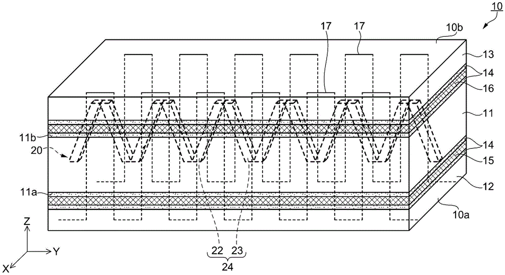
As shown in fig. 6 and 7, the heat flux sensor 10 according to the first embodiment includes a first protective layer 12, a first heat diffusion layer 15, a heat transfer layer 11 as a heat transfer portion, a second heat diffusion layer 16, and a second protective layer 13, which are stacked in this order from the surface 10a side in the + Z direction. The heat flow sensor 10 includes a temperature difference measuring unit 20 incorporated in the heat transfer layer 11.
The heat transfer layer 11 is flat. The surface on the back side (-Z direction side) of the heat transfer layer 11 is defined as a first surface 11a, and the surface on the front side (+ Z direction side) of the heat transfer layer 11 is defined as a second surface 11 b. The heat flow sensor 10 has the following structure: the first thermal diffusion layer 15 and the first protective layer 12 are disposed in this order on the first surface 11a side of the heat transfer layer 11, and the second thermal diffusion layer 16 and the second protective layer 13 are disposed in this order on the second surface 11b side of the heat transfer layer 11.
Adhesive layers 14 are disposed and bonded between the first protective layer 12 and the first thermal diffusion layer 15, between the first thermal diffusion layer 15 and the heat transfer layer 11, between the heat transfer layer 11 and the second thermal diffusion layer 16, and between the second thermal diffusion layer 16 and the second protective layer 13. In addition, the respective layers from the first protective layer 12 to the second protective layer 13 are sewn by sewing threads 17 so that the adjacent layers are joined to each other.
The surface of the first protective layer 12 is the face 10a of the heat flow sensor 10 and the surface of the second protective layer 13 is the face 10b of the heat flow sensor 10. In a state where the electronic apparatus 1 is mounted on the forearm M of the user, the heat flow sensor 10 is configured such that the face 10a is in contact with the surface (skin surface) of the forearm M, the face 10b is exposed to the external environment, and thus the first protective layer 12 is in contact with the skin surface, and the second protective layer 13 is exposed to the external environment.
The structure of each part of the heat flow sensor 10 will be described below. The heat transfer layer 11 is made of a flexible member having good thermal conductivity. More specifically, the heat transfer layer 11 includes a first member having flexibility and a second member having higher thermal conductivity than the first member. In the heat transfer layer 11, the second members are dispersed in the first members, and the volume ratio of the second members is smaller than that of the first members. Therefore, the heat transfer layer 11 has both flexibility and thermal conductivity.
As the first member constituting the base material of the heat transfer layer 11, for example, a material having flexibility and flexibility such as rubber such as natural rubber or synthetic rubber, or soft resin such as polyurethane or silicone can be used. As the second member dispersed in the base material of the heat transfer layer 11, for example, a heat conductive filler such as carbon black powder, carbon fiber, diamond powder, silicon carbide powder, or metal powder can be used.
In order to provide the heat transfer layer 11 with good flexibility and flexibility, the shore hardness of the heat transfer layer 11 (first member) is preferably a hardness of a50 or less. The Shore hardness was measured by a type A durometer specified in JIS K6253. In order to generate a temperature difference for measuring a heat flow between the first surface 11a and the second surface 11b of the heat transfer layer 11, the thickness of the heat transfer layer 11 (first member) is preferably 0.5mm or more and 3mm or less, and more preferably 1.0mm or more and 1.5mm or less.
The thickness of the heat transfer layer 11 is preferably as thin as possible within a range that can generate a temperature difference of measurable heat flow. When the heat transfer layer 11 is thick, heat leaking in the intersecting direction (X-axis direction and Y-axis direction) increases with respect to the heat flow generated in the thickness direction (Z-axis direction) between the first surface 11a and the second surface 11b, and an error may occur in measuring the heat flow.
In order to obtain good response when measuring the heat flow, the thermal conductivity of the heat transfer layer 11 is preferably 10W/(m × K) or more. The thermal conductivity of general rubbers and resins is about 0.1W/(m × K) to 0.5W/(m × K), and the thermal conductivity of the thermally conductive filler is usually 100W/(m × K) or more. By dispersing the second member (thermally conductive filler) in the first member (base material) made of rubber or resin, the thermal conductivity of the heat transfer layer 11 becomes high, and the response when measuring the heat flow is improved. For example, when the second member is dispersed in the first member at a ratio of 10% or more, the thermal conductivity of the heat transfer layer 11 can be set to 10W/(m × K) or more.
The first heat diffusion layer 15 and the second heat diffusion layer 16 are layers for making the temperature distribution in the surface of each of the first surface 11a and the second surface 11b of the heat transfer layer 11 uniform. The thermal conductivities of the first thermal diffusion layer 15 and the second thermal diffusion layer 16 are preferably greater than 100W/(m × K). By making the in-plane temperature distribution of the first surface 11a and the second surface 11b of the heat transfer layer 11 more uniform by the first heat diffusion layer 15 and the second heat diffusion layer 16, the heat flow can be measured in a relatively stable state even if there is a fluctuation due to the contact state of the heat flow sensor 10 with the skin surface or a fluctuation due to the temperature distribution of the skin surface when measuring the heat flow.
The shore hardness of the first and second heat diffusion layers 15 and 16 is preferably not more than a50, and the thickness of the first and second heat diffusion layers 15 and 16 is preferably about 0.1mm to 0.5mm so that the flexibility and flexibility of the heat transfer layer 11 are not impaired. As the material of the first thermal diffusion layer 15 and the second thermal diffusion layer 16, for example, a carbon-based thermally conductive sheet such as a graphite sheet or a carbon sheet, or a metal thin film such as an aluminum sheet or a copper foil can be used.
The first protective layer 12 and the second protective layer 13 are for protecting the heat transfer layer 11, the first thermal diffusion layer 15, and the second thermal diffusion layer 16 from damage caused by accidental contact with another object or the like. It is preferable to use a material made of an organic material such as silicone rubber and having a shore hardness of a50 or less for the first protective layer 12 and the second protective layer 13 so as not to impair the flexibility and the flexibility of the heat transfer layer 11, the first heat diffusion layer 15, and the second heat diffusion layer 16. The material of the first protective layer 12 and the second protective layer 13 may be leather or synthetic leather. The thicknesses of the first protective layer 12 and the second protective layer 13 are preferably about 0.1mm to 0.5mm so that the first thermal diffusion layer 15 and the second thermal diffusion layer 16 can be protected from damage.
As the adhesive layer 14, for example, a known adhesive such as a nitrile rubber adhesive or an acrylic adhesive, which can maintain flexibility even after bonding, can be used. As the adhesive layer 14, a known adhesive in which a thermally conductive filler such as metal powder or carbon fiber is dispersed in the adhesive can be used. The thickness of the adhesive layer 14 is preferably 0.1mm or less. The thickness of the adhesive layer 14 is preferably as thin as possible within the range that can maintain adhesion so as not to compromise the overall flexibility and pliability of the thermal flow sensor 10.
The sewing thread 17 is used to penetrate and sew the heat transfer layer 11, the first thermal diffusion layer 15 and the first protective layer 12 laminated by being bonded with the adhesive layer 14 on the first surface 11a side of the heat transfer layer 11, and the second thermal diffusion layer 16 and the second protective layer 13 laminated by being bonded with the adhesive layer 14 on the second surface 11b side of the heat transfer layer 11. The bonding by the adhesive layer 14 between the layers is not easily peeled off by sewing with the sewing thread 17. As the sewing thread 17, for example, synthetic fibers such as polyester and nylon, or natural fibers such as cotton and hemp can be used.
By stitching with the stitching thread 17, the bond between the layers can be mechanically strengthened without compromising the overall flexibility and flexibility of the thermal flow sensor 10. In order to avoid the temperature difference measurement unit 20 assembled on the heat transfer layer 11, the position of the heat flow sensor 10 stitched by the stitching thread 17 is preferably located at the outer edge portion of the heat flow sensor 10 (see fig. 6). In addition, when the layers of the heat flow sensor 10 can be reliably adhered and bonded by sewing with the sewing thread 17, the adhesive layer 14 may be omitted.
The temperature difference measuring unit 20 is a temperature difference output element embedded in the heat transfer layer 11, and is formed of, for example, a thermopile. A plurality of thermocouples (thermocouples) 24 obtained by bonding both ends of 2 different types of metal conductors 22 and 23 are connected in series so that their hot junctions and cold junctions are located on the first surface 11a (skin surface side) and the second surface 11b (external environment side) of the heat transfer layer 11, respectively, thereby constituting the temperature difference measurement unit 20 (thermopile). Examples of the metal conductors 22 and 23 include nickel-aluminum alloy, nickel-chromium alloy, copper, constantan, and the like.
The heat on the skin surface is transmitted to the first surface 11a of the heat transfer layer 11 through the first heat diffusion layer 15 and the first protective layer 12, and the heat is released from the second surface 11b of the heat transfer layer 11 to the external environment through the second heat diffusion layer 16 and the second protective layer 13. The temperature difference measuring unit 20 outputs a temperature difference between the first surface 11a and the second surface 11b of the heat transfer layer 11, that is, between the hot junction and the cold junction, as a voltage signal. Therefore, the voltage value detected by the voltmeter 25 as the measurement result of the temperature difference measuring unit 20 is output to the control unit 30 (see fig. 7). In the control unit 30, the heat flow measuring unit 31 (see fig. 5) performs a process of measuring the heat flow emitted from the human body (skin surface) based on the measurement result of the temperature difference measuring unit 20.
The temperature difference measuring unit 20 according to the present embodiment is constituted by a thermopile in which a plurality of thermocouples 24 are connected in series. Therefore, the temperature difference measuring section 20 measures the temperature difference based on the temperature information of the plurality of points in the first surface 11a and the temperature information of the plurality of points in the second surface 11b of the heat transfer layer 11. Since the temperature difference can be measured at a plurality of places in the face 10a where the heat flow sensor 10 is in contact with the skin surface as described above, a more average value is obtained than in the case where the temperature difference is measured at only one place. Further, by connecting a plurality of thermocouples 24 in series, a larger voltage signal can be output than in the case where there is one thermocouple 24, and thus the heat flow can be measured more accurately.
In addition, to accurately measure heat (heat dissipation amount) released from the human body, it is necessary to transfer heat of the skin surface to the heat flow sensor without loss. In the electronic device described in patent document 1, since the heat flow sensor itself does not have flexibility, a structure is adopted in which a fitting made of metal or the like having flexibility and good thermal conductivity is brought into contact with the skin surface, and heat of the skin surface is transferred to the heat flow sensor via the fitting. However, in this structure, since a part of heat flows out to other parts before the heat from the skin surface is transferred to the heat flow sensor, an error occurs in measuring the heat flow, and the accuracy of measuring the amount of heat dissipated from the human body is lowered.
Therefore, in order to measure the heat flow without causing an error, it is preferable to suppress the heat transfer loss by directly contacting the heat flow sensor with the skin surface. However, since the conventional heat flow sensor is configured by using a hard material as a base material and has no flexibility, when such a heat flow sensor having no flexibility is brought into contact with an object configured by a curved surface like a human body (forearm M), an air layer is easily generated between the heat flow sensor and the skin surface.
Here, in general, the heat flow sensor outputs, as one voltage signal, a heat flow (temperature difference) detected over the entire area in contact with the object (skin surface). As shown in the above equation (1), since the heat flow Q is proportional to the area a of the object, when the contact area between the heat flow sensor and the object is reduced, the heat flow measured by the heat flow sensor is also reduced.
Therefore, if an air layer is generated in a portion between the heat flow sensor and the skin surface, the substantial contact area between the heat flow sensor and the skin surface is reduced in accordance with the portion in which the air layer is generated, and the heat transmitted to the heat flow sensor is reduced, so that the heat flow measured by the heat flow sensor is smaller than the heat flow actually generated. Further, since the air layer is generated, if the contact area between the heat flow sensor and the skin surface fluctuates when the installer moves or exercises the forearm, the heat flow measured by the heat flow sensor also fluctuates. As a result, in the heat flow sensor having no flexibility, an error occurs in measuring the heat flow, and the accuracy of measuring the amount of heat dissipated from the human body is lowered.
In the electronic apparatus 1 according to the present embodiment, the heat flow sensor 10 is in direct contact with the skin surface. Since the heat flow sensor 10 has flexibility and flexibility, when the electronic device 1 is attached to an object having a curved surface like a human body, the heat flow sensor 10 is bent along the surface of the forearm M and is attached to the skin surface. Therefore, the adhesion with the skin surface is improved, and an air layer is less likely to be generated between the heat flow sensor 10 and the skin surface, and therefore, the decrease in the contact area is suppressed and the variation in the contact area is also suppressed. As a result, errors in measuring the heat flow generated between the skin surface and the external environment can be reduced, and the heat flow of the human body can be measured with high accuracy.
Since the heat flow of the human body is measured with high accuracy by the heat flow sensor 10, the strips 8a and 8b in which the heat flow sensor 10 is embedded are preferably made of a material having lower thermal conductivity than the heat flow sensor 10 (heat transfer layer 11). This is to suppress the heat transferred in the thickness direction of the heat flow sensor 10 from flowing out from the contact portion with the heat flow sensor 10 to the belts 8a and 8b in the direction intersecting the thickness direction of the heat flow sensor 10, and thus to cause an error in measuring the heat flow. The thermal conductivity of the bands 8a, 8b is preferably less than 1W/(m.times.K).
In addition, the strips 8a, 8b are preferably constructed of a material that is the same as or softer than the heat flow sensor 10. This is to bring the heat flow sensor 10 into good contact with an object made of a curved surface like a human body (forearm M) when the electronic apparatus 1 is attached to the human body (forearm M) by the belts 8a, 8 b. The shore hardness of the belts 8a, 8b is preferably below a 50.
(second embodiment)
In the second embodiment, the overall configuration of the electronic apparatus 1 is almost the same as that of the first embodiment, but the configuration of the temperature difference measuring unit in the heat flow sensor is different. Here, the structure of the heat flow sensor (temperature difference measuring unit) according to the second embodiment will be described with respect to the points different from the first embodiment.
Heat flow sensor
A heat flow sensor according to a second embodiment will be described with reference to fig. 8 and 9. Fig. 8 is a perspective view schematically showing the structure of a heat flow sensor according to a second embodiment. Fig. 9 is a sectional view schematically showing the structure of a heat flow sensor according to a second embodiment. The same components as those in the first embodiment are denoted by the same reference numerals, and description thereof is omitted.
As shown in fig. 8 and 9, the heat flow sensor 50 according to the second embodiment has a surface 50a that contacts the skin surface and a surface 50b that contacts the external environment. The heat flux sensor 50 includes a first protective layer 12, a first heat diffusion layer 15, a heat transfer layer 11, a second heat diffusion layer 16, and a second protective layer 13, which are stacked in this order from the surface 50a side in the + Z direction. The heat flux sensor 50 includes a temperature difference measuring unit 20A incorporated in the heat transfer layer 11.
The temperature difference measurement unit 20A includes: a temperature element 26 disposed on the first surface 11a (skin surface side) of the heat transfer layer 11; a temperature element 27 disposed at a position facing the temperature element 26 on the second surface 11b (the external environment side) of the heat transfer layer 11; and a differential amplifier 28 that differentially amplifies the output temperature of the temperature element 26 and the output temperature of the temperature element 27 (see fig. 9). The temperature difference measurement unit 20A outputs the temperature difference between the first surface 11a and the second surface 11b of the heat transfer layer 11 to the control unit 30 (see fig. 9) as a measurement result. The temperature elements 26 and 27 can be thermistors, thermocouples, or the like.
In the control unit 30, the heat flow measuring unit 31 (see fig. 5) performs a process of measuring the heat flow of the human body according to the following expression (2) using the measurement result from the temperature difference measuring unit 20A. In the following formula (2), Q represents heat flow [ W (J/s)]And A represents the area of the object [ m ]2]And λ represents thermal conductivity [ W/(m × K)]And d represents the thickness of the object [ m ]]. Ta represents the output temperature [ K ] of the temperature element 26]And Tb denotes the output temperature [ K ] of the temperature element 27]。
[ formula 2]
When the heat flow sensor 50 according to the second embodiment is embedded in the belts 8a and 8b and used in the electronic device 1, the heat flow sensor 50 having flexibility and flexibility is in direct contact with the skin surface, as in the first embodiment. Therefore, the heat flow generated between the skin surface and the external environment can be measured with high accuracy, and thus the heat flow of the human body can be measured with high accuracy.
Further, when the heat flow sensor 10 (temperature difference measuring unit 20) according to the first embodiment is compared with the heat flow sensor 50 (temperature difference measuring unit 20A) according to the second embodiment, it is understood that the heat flow sensor 10 (temperature difference measuring unit 20) using the thermopile can be made thin and can be easily processed. In addition, the heat flow sensor 10 (temperature difference measuring unit 20) can measure temperature differences at a plurality of positions and can output a large output signal (voltage signal), and therefore, the heat flow can be measured more accurately.
The above embodiment represents only one embodiment of the present invention, and any modification and application can be made within the scope of the present invention. As modified examples, for example, the following are conceivable.
(modification 1)
Although the heat flow sensors 10 and 50 are embedded in a part of the extension direction of the belts 8a and 8b in the above embodiment, the heat flow sensors 10 and 50 may be embedded in the entire extension direction of the belts 8a and 8 b. With this configuration, the area of contact between the heat flow sensors 10 and 50 and the peripheral surface of the forearm M becomes larger, and therefore the accuracy of measuring the heat flow of the human body can be further improved.
(modification 2)
In the above-described embodiment, the structure in which the bands 8a and 8b that engage the hook 9a and the hole 9b are used in order to attach the electronic apparatus 1 to the forearm M of the human body is adopted, but a structure in which a surface fastener or the like is used instead of the hook 9a may be adopted, or a structure in which a band that has no hole and is fixed by a buckle, a nylon buckle (registered trademark), or the like may be used instead of the bands 8a and 8 b.
(modification 3)
Although the electronic apparatus 1 is attached to the forearm M of the human body in the above-described embodiment, the portion to which the electronic apparatus 1 is attached is not limited to the forearm M. For example, the electronic apparatus 1 may be attached to the upper arm, abdomen, thigh, lower leg, ankle, neck, head, or the like. In this case, the belts 8a and 8b may be long, or a part of the belts 8a and 8b may be made of an elastic material. Further, the belts 8a and 8b in which the heat flow sensors 10 and 50 are embedded may be detached from the electronic device 1 and used, or the heat flow sensors 10 and 50 may be separately prepared to have a length or a width suitable for the measurement portion. The object to be measured is not limited to a human body, and may be, for example, an animal body, a stem or branch of a plant, or other artificial objects such as a utility pole or a column.
(modification 4)
Although the heat flow meter that measures the heat flow of the human body is exemplified as the electronic device 1 in the above embodiment, the present invention is not limited to this embodiment. For example, the present invention can be applied to a calorimeter, a calorie consumption meter, a metabolic apparatus, a metabolic function measuring device, an autonomic nerve function measuring device, and the like. In addition, the present invention can also be applied to sports equipment that measures the amount of heat generated by muscles, watch equipment that targets mountaineers, elderly people, children, and the like, toys that reflect events in which the measurement results of biological information are reflected in a virtual space, and the like.