WO2023112251A1 - Temperature measurement device - Google Patents
Temperature measurement device Download PDFInfo
- Publication number
- WO2023112251A1 WO2023112251A1 PCT/JP2021/046505 JP2021046505W WO2023112251A1 WO 2023112251 A1 WO2023112251 A1 WO 2023112251A1 JP 2021046505 W JP2021046505 W JP 2021046505W WO 2023112251 A1 WO2023112251 A1 WO 2023112251A1
- Authority
- WO
- WIPO (PCT)
- Prior art keywords
- temperature
- living body
- sensor
- measuring device
- heat
- Prior art date
Links
- 238000009529 body temperature measurement Methods 0.000 title claims abstract description 11
- 238000001514 detection method Methods 0.000 claims abstract description 10
- 230000002093 peripheral effect Effects 0.000 claims abstract description 4
- 239000000463 material Substances 0.000 claims description 53
- 239000004020 conductor Substances 0.000 claims description 33
- 230000004907 flux Effects 0.000 claims description 26
- 238000005259 measurement Methods 0.000 claims description 10
- 230000036757 core body temperature Effects 0.000 description 19
- 238000010586 diagram Methods 0.000 description 14
- 238000004891 communication Methods 0.000 description 10
- 210000003454 tympanic membrane Anatomy 0.000 description 9
- 238000000034 method Methods 0.000 description 8
- OKTJSMMVPCPJKN-UHFFFAOYSA-N Carbon Chemical compound [C] OKTJSMMVPCPJKN-UHFFFAOYSA-N 0.000 description 6
- 239000002470 thermal conductor Substances 0.000 description 6
- 239000011248 coating agent Substances 0.000 description 5
- 238000000576 coating method Methods 0.000 description 5
- 239000002184 metal Substances 0.000 description 5
- 229910052751 metal Inorganic materials 0.000 description 5
- 229910021393 carbon nanotube Inorganic materials 0.000 description 3
- 239000002041 carbon nanotube Substances 0.000 description 3
- 229910002804 graphite Inorganic materials 0.000 description 3
- 239000010439 graphite Substances 0.000 description 3
- 229920005989 resin Polymers 0.000 description 3
- 239000011347 resin Substances 0.000 description 3
- 238000012546 transfer Methods 0.000 description 3
- 230000036760 body temperature Effects 0.000 description 2
- 230000000694 effects Effects 0.000 description 2
- 210000001061 forehead Anatomy 0.000 description 2
- 150000002739 metals Chemical class 0.000 description 2
- BASFCYQUMIYNBI-UHFFFAOYSA-N platinum Chemical compound [Pt] BASFCYQUMIYNBI-UHFFFAOYSA-N 0.000 description 2
- 230000032258 transport Effects 0.000 description 2
- 239000004642 Polyimide Substances 0.000 description 1
- 229910052782 aluminium Inorganic materials 0.000 description 1
- XAGFODPZIPBFFR-UHFFFAOYSA-N aluminium Chemical compound [Al] XAGFODPZIPBFFR-UHFFFAOYSA-N 0.000 description 1
- -1 and the like Substances 0.000 description 1
- 210000003109 clavicle Anatomy 0.000 description 1
- 230000006835 compression Effects 0.000 description 1
- 238000007906 compression Methods 0.000 description 1
- 238000007796 conventional method Methods 0.000 description 1
- 230000007423 decrease Effects 0.000 description 1
- 239000000835 fiber Substances 0.000 description 1
- 239000004519 grease Substances 0.000 description 1
- 238000009434 installation Methods 0.000 description 1
- 239000007788 liquid Substances 0.000 description 1
- 229910052697 platinum Inorganic materials 0.000 description 1
- 229920001721 polyimide Polymers 0.000 description 1
- 238000012545 processing Methods 0.000 description 1
- 230000036412 respiratory physiology Effects 0.000 description 1
- 229920002379 silicone rubber Polymers 0.000 description 1
- 239000004945 silicone rubber Substances 0.000 description 1
- 239000000758 substrate Substances 0.000 description 1
- 230000002123 temporal effect Effects 0.000 description 1
- 210000000689 upper leg Anatomy 0.000 description 1
- 210000000707 wrist Anatomy 0.000 description 1
Images


Classifications
-
- G—PHYSICS
- G01—MEASURING; TESTING
- G01K—MEASURING TEMPERATURE; MEASURING QUANTITY OF HEAT; THERMALLY-SENSITIVE ELEMENTS NOT OTHERWISE PROVIDED FOR
- G01K13/00—Thermometers specially adapted for specific purposes
- G01K13/20—Clinical contact thermometers for use with humans or animals
-
- A—HUMAN NECESSITIES
- A61—MEDICAL OR VETERINARY SCIENCE; HYGIENE
- A61B—DIAGNOSIS; SURGERY; IDENTIFICATION
- A61B5/00—Measuring for diagnostic purposes; Identification of persons
- A61B5/01—Measuring temperature of body parts ; Diagnostic temperature sensing, e.g. for malignant or inflamed tissue
-
- G—PHYSICS
- G01—MEASURING; TESTING
- G01K—MEASURING TEMPERATURE; MEASURING QUANTITY OF HEAT; THERMALLY-SENSITIVE ELEMENTS NOT OTHERWISE PROVIDED FOR
- G01K1/00—Details of thermometers not specially adapted for particular types of thermometer
- G01K1/02—Means for indicating or recording specially adapted for thermometers
- G01K1/024—Means for indicating or recording specially adapted for thermometers for remote indication
-
- G—PHYSICS
- G01—MEASURING; TESTING
- G01K—MEASURING TEMPERATURE; MEASURING QUANTITY OF HEAT; THERMALLY-SENSITIVE ELEMENTS NOT OTHERWISE PROVIDED FOR
- G01K1/00—Details of thermometers not specially adapted for particular types of thermometer
- G01K1/16—Special arrangements for conducting heat from the object to the sensitive element
-
- G—PHYSICS
- G01—MEASURING; TESTING
- G01K—MEASURING TEMPERATURE; MEASURING QUANTITY OF HEAT; THERMALLY-SENSITIVE ELEMENTS NOT OTHERWISE PROVIDED FOR
- G01K17/00—Measuring quantity of heat
-
- G—PHYSICS
- G01—MEASURING; TESTING
- G01K—MEASURING TEMPERATURE; MEASURING QUANTITY OF HEAT; THERMALLY-SENSITIVE ELEMENTS NOT OTHERWISE PROVIDED FOR
- G01K3/00—Thermometers giving results other than momentary value of temperature
- G01K3/005—Circuits arrangements for indicating a predetermined temperature
Definitions
- the present invention relates to a temperature measuring device that non-invasively and accurately measures the internal temperature of a living body.
- Non-Patent Document 1 discloses a technique of estimating the core body temperature of a living body by assuming a pseudo one-dimensional model of the outside air and the living body.
- Non-Patent Document 1 assumes a one-dimensional model of heat transfer between the living body 100 and the sensor 101 as shown in FIG.
- T air is the temperature of the outside air
- H signal is the heat flux flowing into the sensor 101
- R air is the thermal resistance when the heat flux H signal moves to the outside air
- T skin is the skin of the living body 100 measured by the sensor 101.
- the surface temperature, Tt is the temperature of the upper surface of the sensor 101 on the side opposite to the surface in contact with the living body 100 .
- the core body temperature T body of the living body 100 can be estimated using Equation (1).
- T body T skin + R sensor x H signal (1)
- R sensor (T body - T skin )/(T skin - T t ) (2)
- the deep temperature T body of the living body can be estimated by Equation (1).
- a one-dimensional model is assumed as the heat transfer model of the living body 100 as in the technique disclosed in Non-Patent Document 1
- the heat will flow into the sensor 101 as shown in FIG.
- a heat flux H Leak is generated that moves laterally away from the flow through which the heat that should be expected to travel.
- the thermal resistance between the sensor 101 and the outside air changes due to the wind or outside air temperature, and a heat flux H Leak deviates from the sensor 101, the heat flux that should be measured decreases from H signal to H' signal .
- the conventional technique has a problem that an error occurs in estimating the core body temperature T body due to wind generation and changes in the outside air temperature.
- a temperature measuring device of the present invention comprises a sensor unit configured to measure the magnitude of heat flow transmitted from a living body, and a device configured to calculate the internal temperature of the living body based on the magnitude of the heat flow measured by the sensor unit.
- the sensor unit includes a heat conductor having a hollow structure arranged so that a peripheral edge portion is in contact with the living body, and filling a space between the living body and the heat conductor.
- a first covering material arranged as above
- a detection unit provided in the first covering material so as to measure the magnitude of the heat flow transmitted from the living body, and arranged to cover the heat conductor and a second covering material.
- the electronic circuit section is provided inside the second covering material beside the sensor section.
- the electronic circuit section is provided inside the second covering material on the sensor section.
- one structural example of the temperature measuring device of the present invention is characterized by further comprising a housing provided so as to cover the second outer covering material.
- the detection unit is provided on a surface of the first covering material facing the living body, and configured to measure the temperature of the surface of the living body. 1 temperature sensor, and a second temperature sensor configured to measure the temperature inside the first covering material directly above the first temperature sensor, and the electronic circuit unit comprises the The internal temperature of the living body is calculated based on the measurement results of the first and second temperature sensors. Further, in one configuration example of the temperature measuring device of the present invention, the detection unit is provided on a surface of the first covering material facing the living body, and is configured to measure the temperature of the surface of the living body.
- a heat flux sensor provided on a surface of the first covering material facing the living body and configured to measure a heat flux flowing from the living body into the sensor section, and the electronic circuit section. is characterized by calculating the internal temperature of the living body based on the measurement results of the temperature sensor and the heat flux sensor.
- the heat of the living body is transported through the heat conductor, and the temperature above the detection part is increased, thereby Since it is possible to suppress the lateral heat flow velocity that deviates from the pseudo one-dimensional model, the internal temperature of the living body can be accurately measured even if the temperature around the sensor changes or wind is generated. can do.
- FIG. 1 is a diagram showing the configuration of a temperature measuring device according to a first embodiment of the invention.
- FIG. 2 is an external view of the temperature measuring device according to the first embodiment of the present invention.
- FIG. 3 is a partially cutaway perspective cross-sectional view of a heat conductor according to a first embodiment of the present invention.
- FIG. 4 is a flow chart explaining the operation of the temperature measuring device according to the first embodiment of the present invention.
- 5A to 5D are diagrams showing examples of attaching the temperature measuring device according to the first embodiment of the present invention to a living body.
- 6A to 6C are diagrams showing examples of attaching the temperature measuring device according to the first embodiment of the present invention to a living body.
- FIG. 1 is a diagram showing the configuration of a temperature measuring device according to a first embodiment of the invention.
- FIG. 2 is an external view of the temperature measuring device according to the first embodiment of the present invention.
- FIG. 3 is a partially cutaway perspective cross-sectional view of a heat conduct
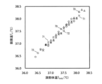
- FIG. 7 is a diagram showing the core body temperature estimated by the temperature measuring device according to the first embodiment of the present invention and the eardrum temperature measured by the eardrum thermometer.
- FIG. 8 is a diagram showing changes over time in the core body temperature estimated by the temperature measuring device according to the first embodiment of the present invention and the eardrum temperature measured by the eardrum thermometer.
- FIG. 9 is a diagram showing the configuration of a temperature measuring device according to a second embodiment of the invention.
- FIG. 10 is an external view of a temperature measuring device according to the second embodiment of the invention.
- FIG. 11 is a flow chart explaining the operation of the temperature measuring device according to the second embodiment of the present invention.
- FIG. 12 is a diagram showing the configuration of a temperature measuring device according to the third embodiment of the invention.
- FIG. 13 is an external view of a temperature measuring device according to the third embodiment of the invention.
- FIG. 14 is a diagram showing the configuration of a temperature measuring device according to the fourth embodiment of the invention.
- FIG. 15 is an external view of a temperature measuring device according to a fourth embodiment of the invention.
- FIG. 16 is a block diagram showing a configuration example of a computer that implements the temperature measuring devices according to the first to fourth embodiments of the present invention.
- FIG. 17 is a diagram showing a thermal equivalent circuit model of a living body and a sensor.
- FIG. 1 is a diagram showing the configuration of a temperature measuring device according to a first embodiment of the present invention
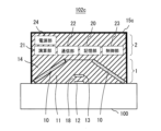
- FIG. 2 is an external view of the temperature measuring device.
- the temperature measurement device 102 includes a sensor unit 1 that measures the magnitude of the heat flow transmitted from the living body 100, and an electronic circuit unit 2 that calculates the core body temperature T body (internal temperature) of the living body 100 based on the measured magnitude of the heat flow. Consists of
- the sensor unit 1 is arranged so that the peripheral part thereof is in contact with the living body 100 .
- the covering material 11 arranged to fill the space between them, the temperature sensor 12 provided on the surface of the covering material 11 facing the living body 100 and measuring the temperature T skin of the skin surface of the living body 100, and the temperature sensor 12 directly above the temperature sensor 12
- the temperature sensors 12 and 13 constitute a detector 18 that measures the magnitude of heat flow.
- the electronic circuit unit 2 includes a storage unit 20 for storing data, a calculation unit 21 for calculating the core body temperature T body of the living body 100 based on the measurement results of the temperature sensors 12 and 13, and the core body temperature T body data.
- a power supply that supplies power to the communication unit 22 that transmits to the external terminal, the control unit 23 that controls the reading and writing of data to the storage unit 20 and communication, and the storage unit 20, the calculation unit 21, the communication unit 22, and the control unit 23.
- a housing 25 that accommodates the storage unit 20 , the calculation unit 21 , the communication unit 22 , the control unit 23 and the power supply unit 24 .
- the sensor unit 1 is worn so that the covering material 11 and the heat conductor 10 are in contact with the skin of the living body 100 .
- the temperature sensors 12 and 13 for example, a thermistor, a thermocouple, a platinum resistor, an IC (Integrated Circuit) temperature sensor, or the like can be used.
- the temperature sensor 13 is arranged directly above the temperature sensor 12 . If the distance between the temperature sensors 12 and 13 changes during measurement, the proportional coefficient R sensor changes and an error occurs in estimating the core body temperature T body of the living body 100. Therefore, the temperature sensors 12 and 13 are held using the covering material 11. do. Considering heat leakage, it is necessary to use a material with a lower thermal conductivity than the thermal conductor 10 as the covering material 11.
- the thermal conductivity of the living body 100 (0.2 to 0.5 W/m It is desirable to use a material with a thermal conductivity similar to that of 2 ).
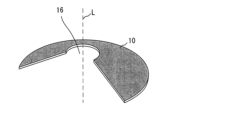
- FIG. 3 is a partially cutaway perspective cross-sectional view of the heat conductor 10.
- the heat conductor 10 has a truncated cone shape in which the top surface away from the living body 100 has a smaller area than the bottom surface facing the living body 100 . It is desirable that the material constituting the heat conductor 10 has a high thermal conductivity in order to efficiently transport the heat flux.
- the heat conductor 10 can be configured using metal such as aluminum.
- materials for the heat conductor 10 include resins containing metals, graphite, carbon nanotubes, and the like, and materials in which metal fibers are woven into a predetermined shape.
- thermal conductivity anisotropy in the in-plane direction perpendicular to the thickness direction is higher than that in the thickness direction. , and flexibility.
- a liquid such as grease containing graphite, carbon nanotubes, or metal may be used as the heat conductor 10 .
- through holes 16 may be formed in the top surface of the heat conductor 10 .
- the heat conductor 10 is sufficiently large with respect to the temperature sensors 12 and 13, the periphery of the heat conductor 10 that contacts the living body 100 is positioned sufficiently away from the temperature sensors 12 and 13. , 13 , the heat flux from the living body 100 is collected by the heat conductor 10 and transported to the top surface of the heat conductor 10 . In this way, the heat conductor 10 efficiently transports the heat flux from the living body 100 upward outside the temperature sensors 12 and 13, thereby suppressing the heat flux that escapes from the temperature sensors 12 and 13 and flows out to the outside air. perform the function of The heat conductor 10 has the highest effect of suppressing the heat flux that diverges from the temperature sensors 12 and 13 and flows out to the outside air at a position near the center line (L in FIG. 3). Therefore, it is desirable to locate the temperature sensors 12 and 13 near the centerline L of the heat conductor 10 .
- the through holes 16 may be formed in the top surface of the heat conductor 10 .
- the through holes 16 may be formed in the top surface of the heat conductor 10 .
- the same material as that of the covering material 11 can be used.
- the same material as the covering materials 11 and 14 may be used. Almost all resin materials can be used for the coating materials 11 and 14 and the housings 15 and 25 .
- the heat conductor 10, and the housing 15 can be deformed according to the complex shape of the living body 100.
- the electronic circuit section 2 is mounted on a flexible substrate such as polyimide and a flexible material is used as the housing 25 , it can be deformed according to the shape of the living body 100 . Therefore, it becomes easy to attach the sensor section 1 and the electronic circuit section 2 to the living body 100 . In addition, it is possible to improve the wearing feeling to the living body 100 .
- FIG. 4 is a flow chart for explaining the operation of the temperature measuring device 102 of this embodiment.
- the temperature sensor 12 measures the temperature T skin of the skin surface of the living body 100 .
- the temperature sensor 13 measures the temperature Tt inside the covering material 11 at a position away from the living body 100 (step S100 in FIG. 4).
- the measurement data of the temperature sensors 12 and 13 are temporarily stored in the storage unit 20 .
- the storage unit 20 stores in advance the proportional coefficient R sensor .
- the calculation unit 21 calculates the core body temperature T body of the living body 100 by, for example, Equation (3) based on the temperatures T skin and T t and the proportionality coefficient R sensor (step S101 in FIG. 4).
- T body T skin + R sensor ⁇ (T skin - T t ) (3)
- Calculating T Skin ⁇ T t as in Equation (3) corresponds to calculating the heat flux H signal in Equation (1).
- the communication unit 22 transmits the data of the core body temperature T body to an external terminal such as a PC (Personal Computer) or a smart phone (step S102 in FIG. 4).
- the external terminal displays the value of core body temperature T body received from temperature measuring device 102 .
- the temperature measurement device 102 performs the above steps S100 to S102 at regular time intervals, for example, until the user gives an instruction to end the measurement (YES in step S103 in FIG. 4).
- the temperature measurement device 102 can be attached to various parts of the living body 100. should be in direct contact with
- the temperature measuring device 102 is attached to the forehead of the living body 100 using double-sided tape for living body.
- the temperature measuring device 102 is attached to the clavicle position of the living body 100 .
- the temperature measuring device 102 is attached to the armpit of the living body 100 using the elastic band 103 .
- the temperature measuring device 102 is attached to the thigh of the living body 100 .
- the temperature measuring device 102 is attached to the upper arm of the living body 100.
- the temperature measuring device 102 is attached to the wrist of the living body 100 .
- the band 103 is used in the examples of FIGS. 5C, 5D, and 6A to 6C, the temperature measurement device 102 may be attached to the living body 100 by pressure from compression wear worn by the living body 100.
- the proportional coefficient R sensor used for estimating the core body temperature can be obtained in advance by measuring the eardrum temperature, the rectal temperature, the armpit temperature, and the like with other sensors as described above.
- a commercially available thermometer is attached to the axillary region of the living body 100 for several minutes, and the temperatures T skin and T t become approximately the same. The temperature at the time of
- the thermal conductor 10 is made of a material with a thermal conductivity of 1 W/m 2 or more, good.
- the heat conductor 10 has a truncated cone shape, the diameter d1 of the through hole 16 is about 8 mm, the diameter d2 of the outer edge of the heat conductor 10 is about 16 mm to 30 mm, the thickness t2 of the heat conductor 10 is 1 mm or more, and the coating material 11 , 14 are made of a material with a thermal conductivity of about 0.2 W/m 2 , the housing 15 is made of the same material as the coating materials 11 and 14, and the thickness of the housing 15 is about 0.5 mm.
- the core body temperature T body can be measured with an accuracy of about ⁇ 0.1°C. If the diameter D of the sensor section 1 is set to 26 mm or less, the thermal conductivity of the heat conductor 10 must be set to 10 W/m 2 or more.
- FIG. 7 shows a deep body temperature T body estimated by attaching the temperature measuring device 102 of the present embodiment to the forehead of the living body 100, and a deep body temperature (tympanic membrane temperature) T e measured by an eardrum thermometer for comparison.
- T body estimated by attaching the temperature measuring device 102 of the present embodiment to the forehead of the living body 100
- . 70, 71, and 72 in FIG. 7 show the results for different living organisms 100, respectively.
- FIG. 8 shows temporal changes in the core body temperature T body and the eardrum temperature T e estimated by the temperature measurement device 102 . From FIGS. 7 and 8, it can be seen that the estimation result close to the eardrum temperature T e is obtained by this embodiment.
- FIG. 9 is a diagram showing the configuration of a temperature measuring device according to a second embodiment of the present invention
- FIG. 10 is an external view of the temperature measuring device.
- a temperature measuring device 102a of this embodiment comprises a sensor section 1a and an electronic circuit section 2a.
- a heat flux sensor 17 is provided on the surface of the covering material 11 of the sensor section 1a facing the living body 100.
- the temperature sensor 12 and the heat flux sensor 17 constitute a detector 18a that measures the magnitude of heat flow.
- Other configurations of the sensor section 1 a are the same as those of the sensor section 1 .
- the electronic circuit section 2 a includes a storage section 20 , an arithmetic section 21 a , a communication section 22 , a control section 23 , a power supply section 24 and a housing 25 .
- FIG. 11 is a flow chart for explaining the operation of the temperature measuring device 102a of this embodiment.
- the temperature sensor 12 measures the temperature T skin of the skin surface of the living body 100 (step S100a in FIG. 11).
- the heat flux sensor 17 measures the heat flux H signal flowing from the living body 100 to the sensor unit 1a (step S104 in FIG. 11).
- the measurement data of the temperature sensor 12 and the heat flux sensor 17 are temporarily stored in the storage unit 20 .
- the storage unit 20 pre-stores the proportional coefficient R sensor .
- the calculation unit 21a calculates the core body temperature T body of the living body 100 by, for example, Equation (1) based on the temperature T skin , the heat flux H signal , and the proportionality coefficient R sensor (step S101a in FIG. 11).
- the communication unit 22 transmits the data of the core body temperature T body to the external terminal (step S102 in FIG. 11).
- the temperature measuring device 102a performs the processes of steps S100a, S104, S101a, and S102 at regular time intervals, for example, until the user gives an instruction to end the measurement (YES in step S103 in FIG. 11).
- steps S100a, S104, S101a, and S102 at regular time intervals, for example, until the user gives an instruction to end the measurement (YES in step S103 in FIG. 11).
- FIG. 12 is a diagram showing the configuration of a temperature measuring device according to a third embodiment of the present invention
- FIG. 13 is an external view of the temperature measuring device.
- a temperature measuring device 102b of this embodiment has a sensor section 1 and an electronic circuit section 2 housed in the same housing 15b.
- the electronic circuit section 2 is provided inside the covering material 14 that covers the thermal conductor 10 of the sensor section 1 .
- the sensor section 1a of the second embodiment may be provided instead of the sensor section 1, and the electronic circuit section 2a of the second embodiment may be provided instead of the electronic circuit section 2.
- the operation of the temperature measuring device 102b is the same as in the first or second embodiment.
- FIG. 14 is a diagram showing the configuration of a temperature measuring device according to a fourth embodiment of the present invention
- FIG. 15 is an external view of the temperature measuring device.
- the temperature measuring device 102c of this embodiment has the electronic circuit section 2 provided on the sensor section 1, and the sensor section 1 and the electronic circuit section 2 are housed in the same housing 15c.
- the electronic circuit section 2 is provided inside the covering material 14 that covers the thermal conductor 10 of the sensor section 1 .
- the installation area of the temperature measuring device 102c can be reduced.
- the sensor section 1a of the second embodiment may be provided instead of the sensor section 1, and the electronic circuit section 2a of the second embodiment may be provided instead of the electronic circuit section 2.
- FIG. The operation of the temperature measuring device 102c is the same as in the first or second embodiment.
- the storage unit 20, the calculation units 21 and 21a, the communication unit 22, and the control unit 23 described in the first to fourth embodiments are a computer having a CPU (Central Processing Unit), a storage device, and an interface, and It can be implemented by a program that controls hardware resources.
- CPU Central Processing Unit
- FIG. 1 A configuration example of this computer is shown in FIG.
- the computer comprises a CPU 200 , a storage device 201 and an interface device (I/F) 202 .
- the hardware of the temperature sensors 12 and 13, the heat flux sensor 17, the communication part 22, etc. are connected to I/F202.
- a program for implementing the temperature measurement method of the present invention is stored in storage device 201 .
- the CPU 200 executes the processes described in the first to fourth embodiments according to the programs stored in the storage device 201. FIG.
- the present invention can be applied to techniques for noninvasively measuring the internal temperature of a living body.
Landscapes
- Physics & Mathematics (AREA)
- General Physics & Mathematics (AREA)
- Health & Medical Sciences (AREA)
- Life Sciences & Earth Sciences (AREA)
- Engineering & Computer Science (AREA)
- Chemical & Material Sciences (AREA)
- Combustion & Propulsion (AREA)
- Pathology (AREA)
- Biophysics (AREA)
- Biomedical Technology (AREA)
- Heart & Thoracic Surgery (AREA)
- Medical Informatics (AREA)
- Molecular Biology (AREA)
- Surgery (AREA)
- Animal Behavior & Ethology (AREA)
- General Health & Medical Sciences (AREA)
- Public Health (AREA)
- Veterinary Medicine (AREA)
- Measuring And Recording Apparatus For Diagnosis (AREA)
Abstract
This temperature measurement device (102) comprises a sensor unit (1) for measuring the magnitude of a thermal flow transmitted from a living body (100), and an electronic circuit unit (2) for calculating the internal temperature of the living body (100) on the basis of the measured magnitude of the thermal flow. The sensor unit (1) is provided with a hollow-structure heat-transmitting body (10) positioned such that the peripheral edge thereof is in contact with the living body, a cover member (11) positioned so as to fill a space between the living body (100) and the heat-transmitting body (10), a detection unit (18) provided to the cover member (11) so as to measure the magnitude of the thermal flow transmitted from the living body (100), and a cover member (14) positioned so as to cover the heat-transmitting body (10).
Description
本発明は、生体の内部温度を非侵襲に精度良く測定する温度測定装置に関するものである。
The present invention relates to a temperature measuring device that non-invasively and accurately measures the internal temperature of a living body.
従来から、生体の深部体温を非侵襲に測定する技術が知られている。例えば、非特許文献1には、外気と生体における疑似的な一次元モデルを仮定して、生体の深部体温を推定する技術が開示されている。
Conventionally, techniques for noninvasively measuring the core body temperature of a living body have been known. For example, Non-Patent Document 1 discloses a technique of estimating the core body temperature of a living body by assuming a pseudo one-dimensional model of the outside air and the living body.
非特許文献1に開示された技術では、図17に示すように生体100とセンサ101の伝熱の1次元モデルを仮定して、生体100の深部体温Tbodyを推定する。図1において、Tairは外気の温度、Hsignalはセンサ101に流入する熱流束、Rairは熱流束Hsignalが外気へ移動するときの熱抵抗、Tskinはセンサ101が測る生体100の皮膚表面の温度、Ttは生体100と接する面と反対側のセンサ101の上面の温度である。生体100の深部体温Tbodyは、式(1)を用いて推定できる。
Tbody=Tskin+Rsensor×Hsignal ・・・(1) The technique disclosed in Non-PatentDocument 1 assumes a one-dimensional model of heat transfer between the living body 100 and the sensor 101 as shown in FIG. In FIG. 1, T air is the temperature of the outside air, H signal is the heat flux flowing into the sensor 101, R air is the thermal resistance when the heat flux H signal moves to the outside air, and T skin is the skin of the living body 100 measured by the sensor 101. The surface temperature, Tt , is the temperature of the upper surface of the sensor 101 on the side opposite to the surface in contact with the living body 100 . The core body temperature T body of the living body 100 can be estimated using Equation (1).
T body = T skin + R sensor x H signal (1)
Tbody=Tskin+Rsensor×Hsignal ・・・(1) The technique disclosed in Non-Patent
T body = T skin + R sensor x H signal (1)
比例係数Rsensorは、測定開始時や測定途中に鼓膜温度計によって測定した鼓膜温度や直腸温度計によって測定した直腸温度、あるいは体温計によって測定した腋窩温度を深部温度Tbody(参照温度)として式(1)に代入することにより、次式のように求めることができる。
Rsensor=(Tbody-Tskin)/(Tskin-Tt) ・・・(2) The proportional coefficient R sensor is expressed by the formula ( By substituting in 1), it can be obtained as in the following equation.
R sensor = (T body - T skin )/(T skin - T t ) (2)
Rsensor=(Tbody-Tskin)/(Tskin-Tt) ・・・(2) The proportional coefficient R sensor is expressed by the formula ( By substituting in 1), it can be obtained as in the following equation.
R sensor = (T body - T skin )/(T skin - T t ) (2)
したがって、皮膚表面の温度Tskinとセンサ101に流入する熱流束Hsignalとを計測することで、式(1)により生体の深部温度Tbodyを推定することができる。
しかしながら、非特許文献1に開示された技術のように生体100の伝熱モデルとして1次元モデルを仮定した場合、風の発生や外気温度の変化などにより、図17に示すようにセンサ101に流入すべき熱が本来通る流れを逸脱して横方向に移動する熱流束HLeakが生じる。風や外気温度によってセンサ101と外気との間の熱抵抗が変化し、センサ101から逸れる熱流束HLeakが発生すると、本来測定されるべき熱流束がHsignalからH’signalに減少する。 Therefore, by measuring the temperature T skin of the skin surface and the heat flux H signal flowing into thesensor 101, the deep temperature T body of the living body can be estimated by Equation (1).
However, when a one-dimensional model is assumed as the heat transfer model of theliving body 100 as in the technique disclosed in Non-Patent Document 1, due to the generation of wind and changes in the outside air temperature, the heat will flow into the sensor 101 as shown in FIG. A heat flux H Leak is generated that moves laterally away from the flow through which the heat that should be expected to travel. When the thermal resistance between the sensor 101 and the outside air changes due to the wind or outside air temperature, and a heat flux H Leak deviates from the sensor 101, the heat flux that should be measured decreases from H signal to H' signal .
しかしながら、非特許文献1に開示された技術のように生体100の伝熱モデルとして1次元モデルを仮定した場合、風の発生や外気温度の変化などにより、図17に示すようにセンサ101に流入すべき熱が本来通る流れを逸脱して横方向に移動する熱流束HLeakが生じる。風や外気温度によってセンサ101と外気との間の熱抵抗が変化し、センサ101から逸れる熱流束HLeakが発生すると、本来測定されるべき熱流束がHsignalからH’signalに減少する。 Therefore, by measuring the temperature T skin of the skin surface and the heat flux H signal flowing into the
However, when a one-dimensional model is assumed as the heat transfer model of the
以上のように、生体100に風が当たったり外気温度が変化したりすると、伝熱の1次元モデルが成立しなくなる。このため、従来の技術では、風の発生や外気温度の変化によって深部体温Tbodyの推定に誤差が生じるという課題があった。
As described above, when the living body 100 is exposed to wind or the ambient temperature changes, the one-dimensional model of heat transfer cannot be established. Therefore, the conventional technique has a problem that an error occurs in estimating the core body temperature T body due to wind generation and changes in the outside air temperature.
本発明は、上記課題を解決するためになされたもので、センサと外気との間の熱抵抗の変化を抑制し、生体の内部温度を精度良く測定することができる温度測定装置を提供することを目的とする。
SUMMARY OF THE INVENTION It is an object of the present invention to provide a temperature measuring device capable of accurately measuring the internal temperature of a living body by suppressing changes in thermal resistance between the sensor and the outside air. With the goal.
本発明の温度測定装置は、生体から伝わる熱流の大きさを測定するように構成されたセンサ部と、前記センサ部によって測定された熱流の大きさに基づいて前記生体の内部温度を算出するように構成された電子回路部とを備え、前記センサ部は、周縁部が前記生体と接するように配置された中空構造の熱伝導体と、前記生体と前記熱伝導体との間の空間を満たすように配置された第1の被覆材と、前記生体から伝わる熱流の大きさを測定するように前記第1の被覆材に設けられた検出部と、前記熱伝導体を覆うように配置された第2の被覆材とを備えることを特徴とするものである。
A temperature measuring device of the present invention comprises a sensor unit configured to measure the magnitude of heat flow transmitted from a living body, and a device configured to calculate the internal temperature of the living body based on the magnitude of the heat flow measured by the sensor unit. and the sensor unit includes a heat conductor having a hollow structure arranged so that a peripheral edge portion is in contact with the living body, and filling a space between the living body and the heat conductor. a first covering material arranged as above, a detection unit provided in the first covering material so as to measure the magnitude of the heat flow transmitted from the living body, and arranged to cover the heat conductor and a second covering material.
また、本発明の温度測定装置の1構成例において、前記電子回路部は、前記センサ部の横の前記第2の被覆材の内部に設けられることを特徴とするものである。
また、本発明の温度測定装置の1構成例において、前記電子回路部は、前記センサ部の上の前記第2の被覆材の内部に設けられることを特徴とするものである。
また、本発明の温度測定装置の1構成例は、外側の前記第2の被覆材を覆うように設けられた筐体をさらに備えることを特徴とするものである。 Further, in one structural example of the temperature measuring device of the present invention, the electronic circuit section is provided inside the second covering material beside the sensor section.
In one configuration example of the temperature measuring device of the present invention, the electronic circuit section is provided inside the second covering material on the sensor section.
Further, one structural example of the temperature measuring device of the present invention is characterized by further comprising a housing provided so as to cover the second outer covering material.
また、本発明の温度測定装置の1構成例において、前記検出部は、前記生体と向かい合う前記第1の被覆材の面に設けられ、前記生体の表面の温度を計測するように構成された第1の温度センサと、前記第1の温度センサの直上の前記第1の被覆材の内部の温度を計測するように構成された第2の温度センサとから構成され、前記電子回路部は、前記第1、第2の温度センサの計測結果に基づいて前記生体の内部温度を算出することを特徴とするものである。
また、本発明の温度測定装置の1構成例において、前記検出部は、前記生体と向かい合う前記第1の被覆材の面に設けられ、前記生体の表面の温度を計測するように構成された温度センサと、前記生体と向かい合う前記第1の被覆材の面に設けられ、前記生体から前記センサ部に流入する熱流束を計測するように構成された熱流束センサとから構成され、前記電子回路部は、前記温度センサと前記熱流束センサの計測結果に基づいて前記生体の内部温度を算出することを特徴とするものである。 Further, in one configuration example of the temperature measuring device of the present invention, the detection unit is provided on a surface of the first covering material facing the living body, and configured to measure the temperature of the surface of the living body. 1 temperature sensor, and a second temperature sensor configured to measure the temperature inside the first covering material directly above the first temperature sensor, and the electronic circuit unit comprises the The internal temperature of the living body is calculated based on the measurement results of the first and second temperature sensors.
Further, in one configuration example of the temperature measuring device of the present invention, the detection unit is provided on a surface of the first covering material facing the living body, and is configured to measure the temperature of the surface of the living body. and a heat flux sensor provided on a surface of the first covering material facing the living body and configured to measure a heat flux flowing from the living body into the sensor section, and the electronic circuit section. is characterized by calculating the internal temperature of the living body based on the measurement results of the temperature sensor and the heat flux sensor.
本発明によれば、検出部から離れた所に熱伝導体を設けることにより、生体の熱を熱伝導体を介して輸送し、検出部の上部の温度を上昇させることで、外気と生体における疑似的な一次元モデルを逸脱する横方向の熱流速を抑制することができるので、センサ部の周囲の温度が変化したり風が生じたりしている場合でも、生体の内部温度を精度良く測定することができる。
According to the present invention, by providing a heat conductor away from the detection part, the heat of the living body is transported through the heat conductor, and the temperature above the detection part is increased, thereby Since it is possible to suppress the lateral heat flow velocity that deviates from the pseudo one-dimensional model, the internal temperature of the living body can be accurately measured even if the temperature around the sensor changes or wind is generated. can do.
[第1の実施例]
以下、本発明の実施例について図面を参照して説明する。図1は本発明の第1の実施例に係る温度測定装置の構成を示す図、図2は温度測定装置の外観図である。温度測定装置102は、生体100から伝わる熱流の大きさを測定するセンサ部1と、測定された熱流の大きさに基づいて生体100の深部体温Tbody(内部温度)を算出する電子回路部2とから構成される。 [First embodiment]
BEST MODE FOR CARRYING OUT THE INVENTION Hereinafter, embodiments of the present invention will be described with reference to the drawings. FIG. 1 is a diagram showing the configuration of a temperature measuring device according to a first embodiment of the present invention, and FIG. 2 is an external view of the temperature measuring device. Thetemperature measurement device 102 includes a sensor unit 1 that measures the magnitude of the heat flow transmitted from the living body 100, and an electronic circuit unit 2 that calculates the core body temperature T body (internal temperature) of the living body 100 based on the measured magnitude of the heat flow. Consists of
以下、本発明の実施例について図面を参照して説明する。図1は本発明の第1の実施例に係る温度測定装置の構成を示す図、図2は温度測定装置の外観図である。温度測定装置102は、生体100から伝わる熱流の大きさを測定するセンサ部1と、測定された熱流の大きさに基づいて生体100の深部体温Tbody(内部温度)を算出する電子回路部2とから構成される。 [First embodiment]
BEST MODE FOR CARRYING OUT THE INVENTION Hereinafter, embodiments of the present invention will be described with reference to the drawings. FIG. 1 is a diagram showing the configuration of a temperature measuring device according to a first embodiment of the present invention, and FIG. 2 is an external view of the temperature measuring device. The
センサ部1は、周縁部が生体100と接するように配置され、生体100からの熱流束をセンサ部1の上部に輸送する中空構造の熱伝導体10と、生体100と熱伝導体10との間の空間を満たすように配置された被覆材11と、生体100と向かい合う被覆材11の面に設けられ、生体100の皮膚表面の温度Tskinを計測する温度センサ12と、温度センサ12の直上の被覆材11の内部の温度Ttを計測する温度センサ13と、熱伝導体10を覆うように配置された被覆材14と、熱伝導体10と被覆材11,14と温度センサ12,13とを収容する筐体15とを備えている。温度センサ12,13は、熱流の大きさを測定する検出部18を構成している。
The sensor unit 1 is arranged so that the peripheral part thereof is in contact with the living body 100 . The covering material 11 arranged to fill the space between them, the temperature sensor 12 provided on the surface of the covering material 11 facing the living body 100 and measuring the temperature T skin of the skin surface of the living body 100, and the temperature sensor 12 directly above the temperature sensor 12 A temperature sensor 13 for measuring the temperature Tt inside the covering material 11, a covering material 14 arranged so as to cover the heat conductor 10, the heat conductor 10, the covering materials 11, 14, and the temperature sensors 12, 13 and a housing 15 that accommodates. The temperature sensors 12 and 13 constitute a detector 18 that measures the magnitude of heat flow.
電子回路部2は、データの記憶のための記憶部20と、温度センサ12,13の測定結果に基づいて生体100の深部体温Tbodyを算出する演算部21と、深部体温Tbodyのデータを外部端末に送信する通信部22と、記憶部20へのデータの読み書きや通信を制御する制御部23と、記憶部20と演算部21と通信部22と制御部23とに電力を供給する電源部24と、記憶部20と演算部21と通信部22と制御部23と電源部24とを収容する筐体25とを備えている。
The electronic circuit unit 2 includes a storage unit 20 for storing data, a calculation unit 21 for calculating the core body temperature T body of the living body 100 based on the measurement results of the temperature sensors 12 and 13, and the core body temperature T body data. A power supply that supplies power to the communication unit 22 that transmits to the external terminal, the control unit 23 that controls the reading and writing of data to the storage unit 20 and communication, and the storage unit 20, the calculation unit 21, the communication unit 22, and the control unit 23. and a housing 25 that accommodates the storage unit 20 , the calculation unit 21 , the communication unit 22 , the control unit 23 and the power supply unit 24 .
センサ部1は、被覆材11と熱伝導体10とが生体100の皮膚と接触するように装着される。例えば生体適合性に優れた両面テープやシリコンラバーを用いてセンサ部1を生体100に装着することが望ましい。温度センサ12,13としては、例えば、サーミスタ、熱電対、白金抵抗体、IC(Integrated Circuit)温度センサなどを用いることができる。
The sensor unit 1 is worn so that the covering material 11 and the heat conductor 10 are in contact with the skin of the living body 100 . For example, it is desirable to attach the sensor unit 1 to the living body 100 using a double-sided tape or silicone rubber having excellent biocompatibility. As the temperature sensors 12 and 13, for example, a thermistor, a thermocouple, a platinum resistor, an IC (Integrated Circuit) temperature sensor, or the like can be used.
温度センサ13は、温度センサ12の直上に配置される。温度センサ12,13の間隔が測定中に変化すると、比例係数Rsensorが変化し、生体100の深部体温Tbodyの推定に誤差が生じるため、温度センサ12,13を被覆材11を用いて保持する。熱の漏れを考慮すると、被覆材11としては、熱伝導体10よりも熱伝導率が小さい材料を使用することが必要であり、生体100の熱伝導率(0.2~0.5W/m2)と同程度の熱伝導率の材料を使用することが望ましい。
The temperature sensor 13 is arranged directly above the temperature sensor 12 . If the distance between the temperature sensors 12 and 13 changes during measurement, the proportional coefficient R sensor changes and an error occurs in estimating the core body temperature T body of the living body 100. Therefore, the temperature sensors 12 and 13 are held using the covering material 11. do. Considering heat leakage, it is necessary to use a material with a lower thermal conductivity than the thermal conductor 10 as the covering material 11. The thermal conductivity of the living body 100 (0.2 to 0.5 W/m It is desirable to use a material with a thermal conductivity similar to that of 2 ).
さらに、被覆材11は、熱伝導体10と温度センサ12,13との相対的位置関係を保持する。図3は熱伝導体10の一部切り欠き斜視断面図である。熱伝導体10は、生体100から離れた天面の面積が生体100側の底面の面積よりも小さい円錐台の形状である。熱伝導体10を構成する材料としては、熱流束を効率良く輸送するために熱伝導率が高いものが望ましい。例えば、熱伝導体10は、アルミニウムなどの金属を用いて構成することができる。
Furthermore, the covering material 11 maintains the relative positional relationship between the thermal conductor 10 and the temperature sensors 12 and 13. FIG. 3 is a partially cutaway perspective cross-sectional view of the heat conductor 10. As shown in FIG. The heat conductor 10 has a truncated cone shape in which the top surface away from the living body 100 has a smaller area than the bottom surface facing the living body 100 . It is desirable that the material constituting the heat conductor 10 has a high thermal conductivity in order to efficiently transport the heat flux. For example, the heat conductor 10 can be configured using metal such as aluminum.
また、熱伝導体10の材料としては金属の他に、金属やグラファイトやカーボンナノチューブなどを含有させた樹脂、金属繊維を所定の形状に編み込んだ材料がある。また、シート状の樹脂の面内にグラファイトやカーボンナノチューブを配向させることで、厚さ方向と垂直な面内方向の熱伝導率が厚さ方向の熱伝導率よりも高い熱伝導異方性と、柔軟性とを有する熱伝導体10を実現することができる。また、グラファイトやカーボンナノチューブや金属を含有させたグリス等の液体を熱伝導体10として用いてもよい。図1、図3で例示したように、熱伝導体10の天面に貫通孔16を形成してもよい。
In addition to metals, materials for the heat conductor 10 include resins containing metals, graphite, carbon nanotubes, and the like, and materials in which metal fibers are woven into a predetermined shape. In addition, by aligning graphite and carbon nanotubes in the plane of the sheet-like resin, thermal conductivity anisotropy in the in-plane direction perpendicular to the thickness direction is higher than that in the thickness direction. , and flexibility. Alternatively, a liquid such as grease containing graphite, carbon nanotubes, or metal may be used as the heat conductor 10 . As illustrated in FIGS. 1 and 3 , through holes 16 may be formed in the top surface of the heat conductor 10 .
熱伝導体10が温度センサ12,13に対して十分に大きい場合、生体100と接する熱伝導体10の周縁部が温度センサ12,13から十分に離れた位置に配置されるので、温度センサ12,13の外側において生体100からの熱流束が熱伝導体10によって集められ、熱伝導体10の天面に輸送される。このように、熱伝導体10は、温度センサ12,13の外側において生体100からの熱流束を効率良く上方に輸送することで、温度センサ12,13から逸れて外気へ流出する熱流束を抑制する機能を果たす。熱伝導体10は、温度センサ12,13から逸れて外気へ流出する熱流束を抑制する効果が、中心線(図3のL)の付近の位置で最も高くなる。したがって、温度センサ12,13を熱伝導体10の中心線Lの近くに配置することが望ましい。
If the heat conductor 10 is sufficiently large with respect to the temperature sensors 12 and 13, the periphery of the heat conductor 10 that contacts the living body 100 is positioned sufficiently away from the temperature sensors 12 and 13. , 13 , the heat flux from the living body 100 is collected by the heat conductor 10 and transported to the top surface of the heat conductor 10 . In this way, the heat conductor 10 efficiently transports the heat flux from the living body 100 upward outside the temperature sensors 12 and 13, thereby suppressing the heat flux that escapes from the temperature sensors 12 and 13 and flows out to the outside air. perform the function of The heat conductor 10 has the highest effect of suppressing the heat flux that diverges from the temperature sensors 12 and 13 and flows out to the outside air at a position near the center line (L in FIG. 3). Therefore, it is desirable to locate the temperature sensors 12 and 13 near the centerline L of the heat conductor 10 .
上記のとおり、熱伝導体10の天面に貫通孔16を形成してもよい。この貫通孔16の大きさを適宜調整することにより、生体100の深部体温Tbodyを測定する場合において測定する深さを調整することが可能となる。ただし、熱伝導体10に貫通孔16を設けることは本発明において必須の構成要件ではない。
As described above, the through holes 16 may be formed in the top surface of the heat conductor 10 . By appropriately adjusting the size of this through-hole 16, it is possible to adjust the depth to be measured when measuring the core body temperature T body of the living body 100. FIG. However, providing the through holes 16 in the heat conductor 10 is not an essential component of the present invention.
被覆材14の材料としては、被覆材11と同じものを用いることができる。また、筐体15,25の材料として、被覆材11,14と同じものを用いてもよい。これら被覆材11,14、筐体15,25としては、ほとんどの樹脂材料を用いることができる。
As the material of the covering material 14, the same material as that of the covering material 11 can be used. Moreover, as the material of the housings 15 and 25, the same material as the covering materials 11 and 14 may be used. Almost all resin materials can be used for the coating materials 11 and 14 and the housings 15 and 25 .
被覆材11,14と熱伝導体10と筐体15として、柔軟性を有する材料を使用すれば、生体100の複雑な形状に合わせて変形することが可能である。同様に、電子回路部2についても、ポリイミドなどのフレキシブル基板上に実装し、筐体25として、柔軟性を有する材料を使用すれば、生体100の形状に合わせて変形することが可能となる。このため、センサ部1と電子回路部2を生体100に装着することが容易となる。また、生体100への装着感を改善することができる。
If flexible materials are used for the coating materials 11 and 14, the heat conductor 10, and the housing 15, they can be deformed according to the complex shape of the living body 100. Similarly, if the electronic circuit section 2 is mounted on a flexible substrate such as polyimide and a flexible material is used as the housing 25 , it can be deformed according to the shape of the living body 100 . Therefore, it becomes easy to attach the sensor section 1 and the electronic circuit section 2 to the living body 100 . In addition, it is possible to improve the wearing feeling to the living body 100 .
温度センサ12,13と電子回路部2との間は配線3によって接続されている。図4は本実施例の温度測定装置102の動作を説明するフローチャートである。温度センサ12は、生体100の皮膚表面の温度Tskinを計測する。温度センサ13は、生体100から遠ざかる位置の被覆材11の内部の温度Ttを計測する(図4ステップS100)。温度センサ12,13の計測データは記憶部20にいったん格納される。
The temperature sensors 12 and 13 and the electronic circuit section 2 are connected by wiring 3 . FIG. 4 is a flow chart for explaining the operation of the temperature measuring device 102 of this embodiment. The temperature sensor 12 measures the temperature T skin of the skin surface of the living body 100 . The temperature sensor 13 measures the temperature Tt inside the covering material 11 at a position away from the living body 100 (step S100 in FIG. 4). The measurement data of the temperature sensors 12 and 13 are temporarily stored in the storage unit 20 .
記憶部20には、比例係数Rsensorが予め記憶されている。演算部21は、温度Tskin,Ttと比例係数Rsensorとに基づいて、生体100の深部体温Tbodyを例えば式(3)により算出する(図4ステップS101)。
Tbody=Tskin+Rsensor×(Tskin-Tt) ・・・(3) Thestorage unit 20 stores in advance the proportional coefficient R sensor . The calculation unit 21 calculates the core body temperature T body of the living body 100 by, for example, Equation (3) based on the temperatures T skin and T t and the proportionality coefficient R sensor (step S101 in FIG. 4).
T body = T skin + R sensor × (T skin - T t ) (3)
Tbody=Tskin+Rsensor×(Tskin-Tt) ・・・(3) The
T body = T skin + R sensor × (T skin - T t ) (3)
なお、式(3)のようにTSkin-Ttを算出することは、式(1)の熱流束Hsignalを算出することに相当する。
通信部22は、深部体温Tbodyのデータを例えばPC(Personal Computer)やスマートフォン等からなる外部端末に送信する(図4ステップS102)。外部端末は、温度測定装置102から受信した深部体温Tbodyの値を表示する。 Calculating T Skin −T t as in Equation (3) corresponds to calculating the heat flux H signal in Equation (1).
Thecommunication unit 22 transmits the data of the core body temperature T body to an external terminal such as a PC (Personal Computer) or a smart phone (step S102 in FIG. 4). The external terminal displays the value of core body temperature T body received from temperature measuring device 102 .
通信部22は、深部体温Tbodyのデータを例えばPC(Personal Computer)やスマートフォン等からなる外部端末に送信する(図4ステップS102)。外部端末は、温度測定装置102から受信した深部体温Tbodyの値を表示する。 Calculating T Skin −T t as in Equation (3) corresponds to calculating the heat flux H signal in Equation (1).
The
温度測定装置102は、以上のステップS100~S102の処理を、例えばユーザから計測終了の指示があるまで(図4ステップS103においてYES)、一定時間毎に実施する。
The temperature measurement device 102 performs the above steps S100 to S102 at regular time intervals, for example, until the user gives an instruction to end the measurement (YES in step S103 in FIG. 4).
図5A~図5D、図6A~図6Cに示すように温度測定装置102を生体100の様々な部位に装着することが可能であるが、いずれの場合においても温度測定装置102は生体100の皮膚に直接接触していることが望ましい。
As shown in FIGS. 5A to 5D and 6A to 6C, the temperature measurement device 102 can be attached to various parts of the living body 100. should be in direct contact with
図5Aの例では、生体用の両面テープを用いて生体100の額に温度測定装置102を貼り付けている。図5Bの例では、生体100の鎖骨の位置に温度測定装置102を貼り付けている。
In the example of FIG. 5A, the temperature measuring device 102 is attached to the forehead of the living body 100 using double-sided tape for living body. In the example of FIG. 5B, the temperature measuring device 102 is attached to the clavicle position of the living body 100 .
図5C、図5Dの例では、伸縮性を有するバンド103を用いて生体100の腋窩部に温度測定装置102を装着している。図6Aの例では、生体100の大腿部に温度測定装置102を装着している。図6Bの例では、生体100の上腕に温度測定装置102を装着している。図6Cの例では、生体100の手首に温度測定装置102を装着している。図5C、図5D、図6A~図6Cの例では、バンド103を用いているが、生体100が着用するコンプレッションウェアによる圧力によって生体100に温度測定装置102を装着してもよい。
In the examples of FIGS. 5C and 5D, the temperature measuring device 102 is attached to the armpit of the living body 100 using the elastic band 103 . In the example of FIG. 6A, the temperature measuring device 102 is attached to the thigh of the living body 100 . In the example of FIG. 6B, the temperature measuring device 102 is attached to the upper arm of the living body 100. In the example of FIG. In the example of FIG. 6C, the temperature measuring device 102 is attached to the wrist of the living body 100 . Although the band 103 is used in the examples of FIGS. 5C, 5D, and 6A to 6C, the temperature measurement device 102 may be attached to the living body 100 by pressure from compression wear worn by the living body 100. FIG.
深部体温推定に用いる比例係数Rsensorについては、前述のように鼓膜温度や直腸温度や腋窩温度等を他のセンサにより測定することにより事前に求めておくことができる。比例係数Rsensorを求める参照温度として腋窩温度を用いる場合には、市販されている体温計を数分程度の間、生体100の腋窩部に装着し、温度TskinとTtとが同程度になった時の温度を参照温度とすればよい。
The proportional coefficient R sensor used for estimating the core body temperature can be obtained in advance by measuring the eardrum temperature, the rectal temperature, the armpit temperature, and the like with other sensors as described above. When the axillary temperature is used as a reference temperature for obtaining the proportionality coefficient R sensor , a commercially available thermometer is attached to the axillary region of the living body 100 for several minutes, and the temperatures T skin and T t become approximately the same. The temperature at the time of
本実施例では、センサ部1を、直径Dが30mm、厚さtが4mmの円柱状とした場合、熱伝導体10を、熱伝導率が1W/m2以上の材料からなるものとすればよい。熱伝導体10を円錐台状とし、貫通孔16の直径d1を8mm程度、熱伝導体10の外縁の直径d2を16mm~30mm程度、熱伝導体10の厚さt2を1mm以上、被覆材11,14を熱伝導率が0.2W/m2程度の材料からなるものとし、筐体15を被覆材11,14と同じ材料からなるものとし、筐体15の厚さを0.5mm程度、温度センサ12と13の間隔を2mm程度とすると、およそ±0.1℃の精度で深部体温Tbodyを測定することができる。なお、センサ部1の直径Dを26mm以下にする場合には、熱伝導体10の熱伝導率を10W/m2以上にする必要がある。
In this embodiment, if the sensor unit 1 is cylindrical with a diameter D of 30 mm and a thickness t of 4 mm, and the thermal conductor 10 is made of a material with a thermal conductivity of 1 W/m 2 or more, good. The heat conductor 10 has a truncated cone shape, the diameter d1 of the through hole 16 is about 8 mm, the diameter d2 of the outer edge of the heat conductor 10 is about 16 mm to 30 mm, the thickness t2 of the heat conductor 10 is 1 mm or more, and the coating material 11 , 14 are made of a material with a thermal conductivity of about 0.2 W/m 2 , the housing 15 is made of the same material as the coating materials 11 and 14, and the thickness of the housing 15 is about 0.5 mm. If the distance between the temperature sensors 12 and 13 is about 2 mm, the core body temperature T body can be measured with an accuracy of about ±0.1°C. If the diameter D of the sensor section 1 is set to 26 mm or less, the thermal conductivity of the heat conductor 10 must be set to 10 W/m 2 or more.
図7に、本実施例の温度測定装置102を生体100の額に装着して推定した深部体温Tbodyと、比較のために鼓膜温度計によって計測した深部温度(鼓膜温)Teとを示す。図7の70,71,72は、それぞれ異なる生体100を対象とする結果を示している。また、図8に、温度測定装置102によって推定した深部体温Tbodyと鼓膜温Teの時間変化を示す。図7、図8によれば、鼓膜温Teに近い推定結果が本実施例によって得られていることが分かる。
FIG. 7 shows a deep body temperature T body estimated by attaching the temperature measuring device 102 of the present embodiment to the forehead of the living body 100, and a deep body temperature (tympanic membrane temperature) T e measured by an eardrum thermometer for comparison. . 70, 71, and 72 in FIG. 7 show the results for different living organisms 100, respectively. FIG. 8 shows temporal changes in the core body temperature T body and the eardrum temperature T e estimated by the temperature measurement device 102 . From FIGS. 7 and 8, it can be seen that the estimation result close to the eardrum temperature T e is obtained by this embodiment.
[第2の実施例]
次に、本発明の第2の実施例について説明する。図9は本発明の第2の実施例に係る温度測定装置の構成を示す図、図10は温度測定装置の外観図である。本実施例の温度測定装置102aは、センサ部1aと、電子回路部2aとから構成される。 [Second embodiment]
Next, a second embodiment of the invention will be described. FIG. 9 is a diagram showing the configuration of a temperature measuring device according to a second embodiment of the present invention, and FIG. 10 is an external view of the temperature measuring device. Atemperature measuring device 102a of this embodiment comprises a sensor section 1a and an electronic circuit section 2a.
次に、本発明の第2の実施例について説明する。図9は本発明の第2の実施例に係る温度測定装置の構成を示す図、図10は温度測定装置の外観図である。本実施例の温度測定装置102aは、センサ部1aと、電子回路部2aとから構成される。 [Second embodiment]
Next, a second embodiment of the invention will be described. FIG. 9 is a diagram showing the configuration of a temperature measuring device according to a second embodiment of the present invention, and FIG. 10 is an external view of the temperature measuring device. A
本実施例は、第1の実施例のセンサ部1の温度センサ13の代わりに、生体100と向かい合うセンサ部1aの被覆材11の面に熱流束センサ17を設けたものである。温度センサ12と熱流束センサ17は、熱流の大きさを測定する検出部18aを構成している。センサ部1aの他の構成は、センサ部1と同じである。
電子回路部2aは、記憶部20と、演算部21aと、通信部22と、制御部23と、電源部24と、筐体25とを備えている。 In this embodiment, instead of thetemperature sensor 13 of the sensor section 1 of the first embodiment, a heat flux sensor 17 is provided on the surface of the covering material 11 of the sensor section 1a facing the living body 100. FIG. The temperature sensor 12 and the heat flux sensor 17 constitute a detector 18a that measures the magnitude of heat flow. Other configurations of the sensor section 1 a are the same as those of the sensor section 1 .
Theelectronic circuit section 2 a includes a storage section 20 , an arithmetic section 21 a , a communication section 22 , a control section 23 , a power supply section 24 and a housing 25 .
電子回路部2aは、記憶部20と、演算部21aと、通信部22と、制御部23と、電源部24と、筐体25とを備えている。 In this embodiment, instead of the
The
図11は本実施例の温度測定装置102aの動作を説明するフローチャートである。第1の実施例と同様に、温度センサ12は、生体100の皮膚表面の温度Tskinを計測する(図11ステップS100a)。
FIG. 11 is a flow chart for explaining the operation of the temperature measuring device 102a of this embodiment. As in the first embodiment, the temperature sensor 12 measures the temperature T skin of the skin surface of the living body 100 (step S100a in FIG. 11).
熱流束センサ17は、生体100からセンサ部1aに流入する熱流束Hsignalを計測する(図11ステップS104)。温度センサ12と熱流束センサ17の計測データは記憶部20にいったん格納される。
The heat flux sensor 17 measures the heat flux H signal flowing from the living body 100 to the sensor unit 1a (step S104 in FIG. 11). The measurement data of the temperature sensor 12 and the heat flux sensor 17 are temporarily stored in the storage unit 20 .
第1の実施例と同様に、記憶部20には、比例係数Rsensorが予め記憶されている。演算部21aは、温度Tskinと熱流束Hsignalと比例係数Rsensorとに基づいて、生体100の深部体温Tbodyを例えば式(1)により算出する(図11ステップS101a)。
通信部22は、深部体温Tbodyのデータを外部端末に送信する(図11ステップS102)。 As in the first embodiment, thestorage unit 20 pre-stores the proportional coefficient R sensor . The calculation unit 21a calculates the core body temperature T body of the living body 100 by, for example, Equation (1) based on the temperature T skin , the heat flux H signal , and the proportionality coefficient R sensor (step S101a in FIG. 11).
Thecommunication unit 22 transmits the data of the core body temperature T body to the external terminal (step S102 in FIG. 11).
通信部22は、深部体温Tbodyのデータを外部端末に送信する(図11ステップS102)。 As in the first embodiment, the
The
温度測定装置102aは、以上のステップS100a,S104,S101a,S102の処理を、例えばユーザから計測終了の指示があるまで(図11ステップS103においてYES)、一定時間毎に実施する。
こうして、本実施例では、第1の実施例と同様の効果を得ることができる。 Thetemperature measuring device 102a performs the processes of steps S100a, S104, S101a, and S102 at regular time intervals, for example, until the user gives an instruction to end the measurement (YES in step S103 in FIG. 11).
Thus, in this embodiment, the same effect as in the first embodiment can be obtained.
こうして、本実施例では、第1の実施例と同様の効果を得ることができる。 The
Thus, in this embodiment, the same effect as in the first embodiment can be obtained.
[第3の実施例]
次に、本発明の第3の実施例について説明する。図12は本発明の第3の実施例に係る温度測定装置の構成を示す図、図13は温度測定装置の外観図である。本実施例の温度測定装置102bは、センサ部1と電子回路部2とを同一の筐体15b内に格納したものである。本実施例では、電子回路部2を、センサ部1の熱伝導体10を覆う被覆材14の内部に設けている。 [Third embodiment]
A third embodiment of the present invention will now be described. FIG. 12 is a diagram showing the configuration of a temperature measuring device according to a third embodiment of the present invention, and FIG. 13 is an external view of the temperature measuring device. Atemperature measuring device 102b of this embodiment has a sensor section 1 and an electronic circuit section 2 housed in the same housing 15b. In this embodiment, the electronic circuit section 2 is provided inside the covering material 14 that covers the thermal conductor 10 of the sensor section 1 .
次に、本発明の第3の実施例について説明する。図12は本発明の第3の実施例に係る温度測定装置の構成を示す図、図13は温度測定装置の外観図である。本実施例の温度測定装置102bは、センサ部1と電子回路部2とを同一の筐体15b内に格納したものである。本実施例では、電子回路部2を、センサ部1の熱伝導体10を覆う被覆材14の内部に設けている。 [Third embodiment]
A third embodiment of the present invention will now be described. FIG. 12 is a diagram showing the configuration of a temperature measuring device according to a third embodiment of the present invention, and FIG. 13 is an external view of the temperature measuring device. A
なお、センサ部1の代わりに第2の実施例のセンサ部1aを設け、電子回路部2の代わりに第2の実施例の電子回路部2aを設けるようにしてもよい。温度測定装置102bの動作は、第1の実施例または第2の実施例と同じである。
The sensor section 1a of the second embodiment may be provided instead of the sensor section 1, and the electronic circuit section 2a of the second embodiment may be provided instead of the electronic circuit section 2. The operation of the temperature measuring device 102b is the same as in the first or second embodiment.
[第4の実施例]
次に、本発明の第4の実施例について説明する。図14は本発明の第4の実施例に係る温度測定装置の構成を示す図、図15は温度測定装置の外観図である。本実施例の温度測定装置102cは、センサ部1の上に電子回路部2を設け、センサ部1と電子回路部2とを同一の筐体15c内に格納したものである。本実施例では、電子回路部2を、センサ部1の熱伝導体10を覆う被覆材14の内部に設けている。 [Fourth embodiment]
A fourth embodiment of the present invention will now be described. FIG. 14 is a diagram showing the configuration of a temperature measuring device according to a fourth embodiment of the present invention, and FIG. 15 is an external view of the temperature measuring device. Thetemperature measuring device 102c of this embodiment has the electronic circuit section 2 provided on the sensor section 1, and the sensor section 1 and the electronic circuit section 2 are housed in the same housing 15c. In this embodiment, the electronic circuit section 2 is provided inside the covering material 14 that covers the thermal conductor 10 of the sensor section 1 .
次に、本発明の第4の実施例について説明する。図14は本発明の第4の実施例に係る温度測定装置の構成を示す図、図15は温度測定装置の外観図である。本実施例の温度測定装置102cは、センサ部1の上に電子回路部2を設け、センサ部1と電子回路部2とを同一の筐体15c内に格納したものである。本実施例では、電子回路部2を、センサ部1の熱伝導体10を覆う被覆材14の内部に設けている。 [Fourth embodiment]
A fourth embodiment of the present invention will now be described. FIG. 14 is a diagram showing the configuration of a temperature measuring device according to a fourth embodiment of the present invention, and FIG. 15 is an external view of the temperature measuring device. The
本実施例によれば、温度測定装置102cの設置面積を小さくすることができる。なお、センサ部1の代わりに第2の実施例のセンサ部1aを設け、電子回路部2の代わりに第2の実施例の電子回路部2aを設けるようにしてもよい。温度測定装置102cの動作は、第1の実施例または第2の実施例と同じである。
According to this embodiment, the installation area of the temperature measuring device 102c can be reduced. The sensor section 1a of the second embodiment may be provided instead of the sensor section 1, and the electronic circuit section 2a of the second embodiment may be provided instead of the electronic circuit section 2. FIG. The operation of the temperature measuring device 102c is the same as in the first or second embodiment.
第1~第4の実施例で説明した記憶部20と演算部21,21aと通信部22と制御部23とは、CPU(Central Processing Unit)、記憶装置及びインタフェースを備えたコンピュータと、これらのハードウェア資源を制御するプログラムによって実現することができる。このコンピュータの構成例を図16に示す。
The storage unit 20, the calculation units 21 and 21a, the communication unit 22, and the control unit 23 described in the first to fourth embodiments are a computer having a CPU (Central Processing Unit), a storage device, and an interface, and It can be implemented by a program that controls hardware resources. A configuration example of this computer is shown in FIG.
コンピュータは、CPU200と、記憶装置201と、インタフェース装置(I/F)202とを備えている。I/F202には、温度センサ12,13、熱流束センサ17、通信部22のハードウェア等が接続される。このようなコンピュータにおいて、本発明の温度測定方法を実現させるためのプログラムは、記憶装置201に格納される。CPU200は、記憶装置201に格納されたプログラムに従って第1~第4の実施例で説明した処理を実行する。
The computer comprises a CPU 200 , a storage device 201 and an interface device (I/F) 202 . The hardware of the temperature sensors 12 and 13, the heat flux sensor 17, the communication part 22, etc. are connected to I/F202. In such a computer, a program for implementing the temperature measurement method of the present invention is stored in storage device 201 . The CPU 200 executes the processes described in the first to fourth embodiments according to the programs stored in the storage device 201. FIG.
本発明は、生体の内部温度を非侵襲に測定する技術に適用することができる。
The present invention can be applied to techniques for noninvasively measuring the internal temperature of a living body.
1,1a…センサ部、2,2a…電子回路部、10…熱伝導体、11,14…被覆材、12,13…温度センサ、15,15b,15c,25…筐体、17…熱流束センサ、18,18a…検出部、20…記憶部、21,21a…演算部、22…通信部、23…制御部、24…電源部、102,102a~102c…温度測定装置。
DESCRIPTION OF SYMBOLS 1, 1a... Sensor part 2, 2a... Electronic circuit part 10... Thermal conductor 11, 14... Coating material 12, 13... Temperature sensor 15, 15b, 15c, 25... Case, 17... Heat flux Sensors 18, 18a... Detection unit 20... Storage unit 21, 21a... Calculation unit 22... Communication unit 23... Control unit 24... Power supply unit 102, 102a to 102c... Temperature measuring device.
Claims (6)
- 生体から伝わる熱流の大きさを測定するように構成されたセンサ部と、
前記センサ部によって測定された熱流の大きさに基づいて前記生体の内部温度を算出するように構成された電子回路部とを備え、
前記センサ部は、
周縁部が前記生体と接するように配置された中空構造の熱伝導体と、
前記生体と前記熱伝導体との間の空間を満たすように配置された第1の被覆材と、
前記生体から伝わる熱流の大きさを測定するように前記第1の被覆材に設けられた検出部と、
前記熱伝導体を覆うように配置された第2の被覆材とを備えることを特徴とする温度測定装置。 a sensor unit configured to measure the magnitude of the heat flow transmitted from the living body;
an electronic circuit unit configured to calculate the internal temperature of the living body based on the magnitude of the heat flow measured by the sensor unit;
The sensor unit is
a heat conductor with a hollow structure arranged so that the peripheral portion is in contact with the living body;
a first covering arranged to fill a space between the living body and the heat conductor;
a detection unit provided in the first covering material so as to measure the magnitude of the heat flow transmitted from the living body;
and a second covering member arranged to cover the heat conductor. - 請求項1記載の温度測定装置において、
前記電子回路部は、前記センサ部の横の前記第2の被覆材の内部に設けられることを特徴とする温度測定装置。 The temperature measurement device according to claim 1,
The temperature measuring device, wherein the electronic circuit section is provided inside the second covering material beside the sensor section. - 請求項1記載の温度測定装置において、
前記電子回路部は、前記センサ部の上の前記第2の被覆材の内部に設けられることを特徴とする温度測定装置。 The temperature measurement device according to claim 1,
The temperature measuring device, wherein the electronic circuit section is provided inside the second covering material on the sensor section. - 請求項1乃至3のいずれか1項に記載の温度測定装置において、
外側の前記第2の被覆材を覆うように設けられた筐体をさらに備えることを特徴とする温度測定装置。 The temperature measurement device according to any one of claims 1 to 3,
A temperature measuring device, further comprising a housing provided to cover the second covering material on the outside. - 請求項1乃至4のいずれか1項に記載の温度測定装置において、
前記検出部は、
前記生体と向かい合う前記第1の被覆材の面に設けられ、前記生体の表面の温度を計測するように構成された第1の温度センサと、
前記第1の温度センサの直上の前記第1の被覆材の内部の温度を計測するように構成された第2の温度センサとから構成され、
前記電子回路部は、前記第1、第2の温度センサの計測結果に基づいて前記生体の内部温度を算出することを特徴とする温度測定装置。 The temperature measuring device according to any one of claims 1 to 4,
The detection unit is
a first temperature sensor provided on a surface of the first covering material facing the living body and configured to measure the surface temperature of the living body;
a second temperature sensor configured to measure the temperature inside the first covering immediately above the first temperature sensor;
The temperature measuring device, wherein the electronic circuit section calculates the internal temperature of the living body based on the measurement results of the first and second temperature sensors. - 請求項1乃至4のいずれか1項に記載の温度測定装置において、
前記検出部は、
前記生体と向かい合う前記第1の被覆材の面に設けられ、前記生体の表面の温度を計測するように構成された温度センサと、
前記生体と向かい合う前記第1の被覆材の面に設けられ、前記生体から前記センサ部に流入する熱流束を計測するように構成された熱流束センサとから構成され、
前記電子回路部は、前記温度センサと前記熱流束センサの計測結果に基づいて前記生体の内部温度を算出することを特徴とする温度測定装置。 The temperature measuring device according to any one of claims 1 to 4,
The detection unit is
a temperature sensor provided on the surface of the first covering material facing the living body and configured to measure the temperature of the surface of the living body;
a heat flux sensor provided on the surface of the first covering material facing the living body and configured to measure the heat flux flowing from the living body into the sensor unit,
The temperature measuring device, wherein the electronic circuit section calculates the internal temperature of the living body based on the measurement results of the temperature sensor and the heat flux sensor.
Priority Applications (3)
| Application Number | Priority Date | Filing Date | Title |
|---|---|---|---|
| PCT/JP2021/046505 WO2023112251A1 (en) | 2021-12-16 | 2021-12-16 | Temperature measurement device |
| US18/701,134 US20240353271A1 (en) | 2021-12-16 | 2021-12-16 | Temperature measurement device |
| JP2023567430A JPWO2023112251A1 (en) | 2021-12-16 | 2021-12-16 |
Applications Claiming Priority (1)
| Application Number | Priority Date | Filing Date | Title |
|---|---|---|---|
| PCT/JP2021/046505 WO2023112251A1 (en) | 2021-12-16 | 2021-12-16 | Temperature measurement device |
Publications (1)
| Publication Number | Publication Date |
|---|---|
| WO2023112251A1 true WO2023112251A1 (en) | 2023-06-22 |
Family
ID=86773829
Family Applications (1)
| Application Number | Title | Priority Date | Filing Date |
|---|---|---|---|
| PCT/JP2021/046505 WO2023112251A1 (en) | 2021-12-16 | 2021-12-16 | Temperature measurement device |
Country Status (3)
| Country | Link |
|---|---|
| US (1) | US20240353271A1 (en) |
| JP (1) | JPWO2023112251A1 (en) |
| WO (1) | WO2023112251A1 (en) |
Citations (4)
| Publication number | Priority date | Publication date | Assignee | Title |
|---|---|---|---|---|
| JPS61120027A (en) * | 1984-11-16 | 1986-06-07 | Hitachi Ltd | Simple type clinical thermometer for deep part |
| JPS6358223A (en) * | 1986-08-29 | 1988-03-14 | Tatsuo Togawa | Clinical thermometer device |
| US20180008149A1 (en) * | 2016-07-06 | 2018-01-11 | General Electric Company | Systems and Methods of Body Temperature Measurement |
| JP2020176934A (en) * | 2019-04-19 | 2020-10-29 | 日本電信電話株式会社 | Temperature measuring device and temperature measuring method |
-
2021
- 2021-12-16 US US18/701,134 patent/US20240353271A1/en active Pending
- 2021-12-16 JP JP2023567430A patent/JPWO2023112251A1/ja active Pending
- 2021-12-16 WO PCT/JP2021/046505 patent/WO2023112251A1/en active Application Filing
Patent Citations (4)
| Publication number | Priority date | Publication date | Assignee | Title |
|---|---|---|---|---|
| JPS61120027A (en) * | 1984-11-16 | 1986-06-07 | Hitachi Ltd | Simple type clinical thermometer for deep part |
| JPS6358223A (en) * | 1986-08-29 | 1988-03-14 | Tatsuo Togawa | Clinical thermometer device |
| US20180008149A1 (en) * | 2016-07-06 | 2018-01-11 | General Electric Company | Systems and Methods of Body Temperature Measurement |
| JP2020176934A (en) * | 2019-04-19 | 2020-10-29 | 日本電信電話株式会社 | Temperature measuring device and temperature measuring method |
Also Published As
| Publication number | Publication date |
|---|---|
| US20240353271A1 (en) | 2024-10-24 |
| JPWO2023112251A1 (en) | 2023-06-22 |
Similar Documents
| Publication | Publication Date | Title |
|---|---|---|
| US9015001B2 (en) | Temperature measurement device and temperature measuring method | |
| US9528887B2 (en) | Temperature measurement device | |
| US9562811B2 (en) | Temperature sensor structure | |
| US7299090B2 (en) | Arrangement for measuring the body temperature of a living organism | |
| US20180028070A1 (en) | Wearable thermometer patch for correct measurement of human skin temperature | |
| US20180028069A1 (en) | Wearable thermometer patch for accurate measurement of human skin temperature | |
| US20190038455A1 (en) | Ambient Condition Resistant Body Mountable Thermal Coupling Devices | |
| JPS6358223A (en) | Clinical thermometer device | |
| CN107951471A (en) | Axillaty temperature measuring device and use its body temperature measurement method | |
| JP2013044624A (en) | Clinical thermometer | |
| WO2023112251A1 (en) | Temperature measurement device | |
| JP2018151322A (en) | Internal temperature measuring device | |
| JP2017223548A (en) | Measuring device and wearable apparatus | |
| CN105919552B (en) | Heat flow meter and electronic device | |
| US20240344904A1 (en) | Temperature measurement device | |
| WO2023067753A1 (en) | Temperature measuring device | |
| WO2023161998A1 (en) | Temperature measurement device | |
| JP5737452B2 (en) | Thermometer and temperature measurement method | |
| JP2016133484A (en) | Heat flow sensor and electronic apparatus | |
| WO2019182095A1 (en) | Body temperature measurement device | |
| JP7367878B2 (en) | measuring device | |
| US11974831B2 (en) | Apparatus and method for estimating body temperature | |
| US20220349758A1 (en) | Wearable Environmental Sensor Device and Monitoring System | |
| US20230341275A1 (en) | Electronic device and method of measuring air temperature using the same | |
| JP7388266B2 (en) | ear thermometer |
Legal Events
| Date | Code | Title | Description |
|---|---|---|---|
| 121 | Ep: the epo has been informed by wipo that ep was designated in this application |
Ref document number: 21968166 Country of ref document: EP Kind code of ref document: A1 |
|
| WWE | Wipo information: entry into national phase |
Ref document number: 18701134 Country of ref document: US |
|
| ENP | Entry into the national phase |
Ref document number: 2023567430 Country of ref document: JP Kind code of ref document: A |
|
| NENP | Non-entry into the national phase |
Ref country code: DE |