CN103457242A - Electric furnace transformer longitudinal differential protection secondary current compensation method - Google Patents
Electric furnace transformer longitudinal differential protection secondary current compensation method Download PDFInfo
- Publication number
- CN103457242A CN103457242A CN2013103441552A CN201310344155A CN103457242A CN 103457242 A CN103457242 A CN 103457242A CN 2013103441552 A CN2013103441552 A CN 2013103441552A CN 201310344155 A CN201310344155 A CN 201310344155A CN 103457242 A CN103457242 A CN 103457242A
- Authority
- CN
- China
- Prior art keywords
- centerdot
- current
- transformer
- furnace transformer
- voltage side
- Prior art date
- Legal status (The legal status is an assumption and is not a legal conclusion. Google has not performed a legal analysis and makes no representation as to the accuracy of the status listed.)
- Pending
Links
Images
Landscapes
- Protection Of Transformers (AREA)
Abstract
The invention relates to an electric furnace transformer longitudinal differential protection secondary current compensation method. The low voltage side of an electric furnace transformer is a delta connection, and a current mutual inductor is installed inside a delta; the secondary currents on both the high voltage side and the low voltage side are not compensated, and only the secondary current on the medium voltage side of the delta connection is compensated. According to the method and furnace transformer longitudinal differential protection, secondary current on the high, medium and low voltage side TA of the transformer is rotated, and then difference current calculation is conducted on the secondary current, longitudinal differential protection can not be operated by mistake when the transformer is normally operated and external short-circuit faults occur and can be sensitively moved when internal short-circuit faults occur. The method is high in sensitivity when the faults occur, and maloperation can be avoided.
Description
Technical field
The present invention relates to the compensation method of secondary current in a kind of furnace transformer longitudinal difference protection field, particularly longitudinal difference protection.
Background technology
Each side current transformer (TA) of microcomputer type longitudinal difference protection is Y and connects; not malfunction of longitudinal difference protection during for normal operation; in the time of must guaranteeing normal operation, differential current is zero (actual is less unsymmetrical current) in theory; thereby can guarantee that longitudinal difference protection moves during not malfunction ,Zhi district internal short-circuit fault when the normal operation of transformer and external short-circuit fault.For reaching this purpose, the TA secondary side current of all transformers (comprising furnace transformer) microcomputer type longitudinal difference protection need carry out reasonable compensation (being commonly called as corner).Below introduce the method for conventional electric power transformer microcomputer longitudinal difference protection Current Transformer Secondary side electric current corner.
With traditional Y/ △-11 or Y
0/ △-11 power transformer is example, and the method for analyzing its Microcomputer Differential Current Protection Current Transformer Secondary side current compensation (being commonly called as corner) is as follows:
Conventional electric power transformer △ side current transformer TA
lbe installed in the outlet of transformer △ side winding TA
lthe primary side current line current that is the △ output line.TA during normal operation
lthe primary side current leading in Y side current transformer TA
hwith 30 ° of famous prime minister's primary side currents, TA again
l, TA
hsecondary side is all that Y connects, thus in the forward-order current situation TA
lthe positive direction of secondary side current (as
 ) also leading is in TA
hsecondary side phase current of the same name (as
) also leading is in TA
hsecondary side phase current of the same name (as
 ) 30 °, see Fig. 1.If TA
l, TA
hsecondary side current do not compensate, directly by TA
l, TA
hsecondary current be transported to CPU and participate in longitudinal difference protection differential current I
opdeng calculating, due to TA
l, TA
hsame famous prime minister's secondary current positive direction (as
) 30 °, see Fig. 1.If TA
l, TA
hsecondary side current do not compensate, directly by TA
l, TA
hsecondary current be transported to CPU and participate in longitudinal difference protection differential current I
opdeng calculating, due to TA
l, TA
hsame famous prime minister's secondary current positive direction (as
 ) phase difference be 30 °, must cause the differential current I calculated when normal operation
op≠ 0 and I
opvalue is large, makes the longitudinal difference protection misoperation, and this is unallowed.So traditional Y/ △-11 power transformer Y side TA
hsecondary current need compensate, and sees formula (1 first), and △ side TA
lthe secondary current uncompensation, be shown in formula (1 second), i.e. Y side secondary current corner and △ side secondary current corner not.
) phase difference be 30 °, must cause the differential current I calculated when normal operation
op≠ 0 and I
opvalue is large, makes the longitudinal difference protection misoperation, and this is unallowed.So traditional Y/ △-11 power transformer Y side TA
hsecondary current need compensate, and sees formula (1 first), and △ side TA
lthe secondary current uncompensation, be shown in formula (1 second), i.e. Y side secondary current corner and △ side secondary current corner not.
、
See Fig. 1 phasor analysis, only have forward-order current when normal operation,
 and
and
 (perunit value that refers to the two amplitude equates), according to formula (1 first) and Fig. 1,
 tA during normal operation
hprimary current from positive ends, flow into, secondary current (as
tA during normal operation
hprimary current from positive ends, flow into, secondary current (as
 ) for just, and TA
lthe primary current polar end of thinking highly of oneself flow into, secondary current (as
) for just, and TA
lthe primary current polar end of thinking highly of oneself flow into, secondary current (as
 ) for negative, according to formula (1 second), obtain again
the differential current of longitudinal difference protection A phase
) for negative, according to formula (1 second), obtain again
the differential current of longitudinal difference protection A phase
Be actually unsymmetrical current, visible traditional Y/ △-11 (or Y
0reliably not malfunction of longitudinal difference protection when/△-11) power transformer carries out TA secondary current compensation and can guarantee normally to move by formula (1 first), formula (1 second).
Tradition Y/Y-12/ △-11 or Y
0the method of/Y-12/ △-11 power transformer Microcomputer Differential Current Protection Current Transformer Secondary side current compensation (being commonly called as corner) is:
High-pressure side (Y or Y
0wiring) current transformer TA
hsecondary current (is equivalent to TA in the forward-order current situation by formula (2 first) compensation
h30 ° of the constant forwards of secondary current amplitude); Medium voltage side (Y wiring) current transformer TA
msecondary current (is equivalent to TA in the forward-order current situation by formula (2 second) compensation
m30 ° of the constant forwards of secondary current amplitude); Low-pressure side (delta connection) current transformer TA
lsecondary current uncompensation (not corner), be shown in formula (2 third).
In like manner, traditional Y/ △-11/ △-11 or Y
0the method of/△-11/ △-11 power transformer Microcomputer Differential Current Protection Current Transformer Secondary current compensation (being commonly called as corner) is:
High-pressure side (Y or Y
0wiring) TA
hsecondary current (is equivalent to TA in the forward-order current situation by formula (3 first) compensation
h30 ° of the constant forwards of secondary current amplitude); Medium voltage side (delta connection) TA
msecondary current uncompensation (not corner), be shown in formula (3 second); Low-pressure side (delta connection) TA
lsecondary side current uncompensation (not corner), be shown in formula (3 third).
Formula (1 first, 1 second), formula (2 first, 2 second, 2 third), in formula (3 first, 3 second, 3 third)

 be respectively the three-phase current of conventional electric power transformer high, medium and low voltage side Current Transformer Secondary side, i.e. three-phase current before the compensation;
 be respectively the three-phase current after the conventional electric power transformer compensates, participate in differential current I in CPU
opthree-phase current Deng calculating, be called the calculating electric current.
be respectively the three-phase current after the conventional electric power transformer compensates, participate in differential current I in CPU
opthree-phase current Deng calculating, be called the calculating electric current.
For furnace transformer; its low pressure winding to the wiring between load (three electrodes of arc furnace) is very special delta connection; furnace transformer longitudinal difference protection low-pressure side current transformer TA used can only be contained in triangle inside; TA can be contained on leg-of-mutton output lead without any way, can only measure the phase current of low pressure winding.And the conventional electric power transformer longitudinal that the low pressure winding is delta connection low-pressure side TA used is contained on the three-phase conducting wire of triangle output, measure the line current of triangle output.
The outer large capacity electric stove transformer of Present Domestic all only has simple overcurrent protection, without longitudinal difference protection, safe operation is worked the mischief.And, the low-pressure side TA electric current measured due to the furnace transformer longitudinal difference protection and the measurement electric current different in kind of conventional electric power step down side TA, if still according to the equations of rotating angle of conventional electric power transformer differential protection, high, medium and low voltage side TA secondary current is carried out to corner therefore electric furnace becomes longitudinal difference protection, must cause electric furnace to become longitudinal difference protection misoperation when the normal operation of transformer and external short-circuit fault; Compensate (seeing embodiment 1.3 partial analysis) according to conventional thought, when troubles inside the sample space sensitivity very poor, this is all unallowed certainly.
Summary of the invention
The purpose of this invention is to provide a kind of secondary current compensation method of furnace transformer longitudinal difference protection, in order to solve, the compensation method of conventional electric power transformer is applied to the malfunction that power transformer causes, the problem of poor sensitivity.
For achieving the above object, the solution of the present invention comprises:
Low-pressure side is delta connection, and the low-pressure side current transformer is arranged on triangle inside; When compensation is calculated, only compensate the medium voltage side secondary current of delta connection, by its corner, be the calculating electric current calculated for longitudinal difference protection.
Y/ △-11/ △-11 furnace transformer, adopt
Y/Y-12/ △-11 furnace transformer, adopt
Y/ △-11 furnace transformer, adopt
The furnace transformer longitudinal difference protection of the present invention's development has been filled up this blank both domestic and external; safe operation is brought into play to very big usefulness; and one of key technology of setting up the furnace transformer longitudinal difference protection is the compensation equation of each side Current Transformer Secondary electric current of appropriate design, the compensation equation of it and conventional electric power transformer differential protection has remarkable difference.
Electric furnace becomes longitudinal difference protection, according to said method of the present invention, the secondary current of transformer high, medium and low voltage side TA is carried out to corner; then carry out differential current computing; just can guarantee longitudinal difference protection not malfunction when the normal operation of transformer and external short-circuit fault; sensitive action during Er district internal short-circuit fault, this is creative embody (embodiment 1.3 is shown in concrete analysis) of the present invention just.
The accompanying drawing explanation
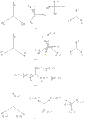
Fig. 1 is the phasor analysis figure of traditional Y/ △-11 Power Transformer Longitudinal Differential Protection Current Transformer Secondary side current compensation;
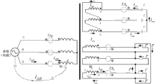
Fig. 2 is that Y/ Δ-11/ Δ-11 furnace transformer is simplified schematic circuit and the external line chart of longitudinal difference protection terminal thereof;
Fig. 3 (first), (second), (third), (fourth) are Y/ Δ-11/ Δ-11 furnace transformer longitudinal difference protection electric current phasor figure when normal operation of employing formula (5 first, 5 second, 5 third) compensation; Fig. 3 (first) is TA
h, TA
m, TA
lprimary side current; Fig. 3 (second) is TA
h, TA
m, TA
lsecondary side current is the timing situation; Fig. 3 (third) is TA
mthe secondary side current intermediate operations; Fig. 3 (fourth) is TA
hsecondary side current for just, TA
m, TA
lsituation when secondary side current is negative;
Fig. 4 is Y/ Δ-11/ Δ-11 furnace transformer high-pressure side winding A phase single-line to ground fault current characteristic figure.
Embodiment
Below in conjunction with accompanying drawing, the present invention will be further described in detail.The large capacity electric stove high voltage side of transformer is nearly all access 110KV solidly earthed neutral system, but furnace transformer high-pressure side winding neutral point to be in operation be all earth-free.
1.Y/ △-11/ △-11 furnace transformer longitudinal difference protection TA secondary current compensation equation
Y/ △-11/ △-11 furnace transformer is as shown in Figure 2 simplified schematic circuit and the external line chart of longitudinal difference protection terminal thereof.In figure,
TA
h, TA
m, TA
l---furnace transformer senior middle school low-pressure side current transformer;


---medium voltage side TA
msecondary side current;

The three-phase current when electric current that in figure, arrow indicates is normal operation.
Be very peculiar Y/ △-11 wiring between three utmost points of furnace transformer low-pressure side three phase windings and arc furnace, see the lower-voltage circuit of Fig. 2, all furnace transformer low-pressure sides are all this wiring, cause and flow through TA
lthe electric current of primary side is the phase current of furnace transformer three-phase low-voltage winding, is the three-phase phase current in △ shape, is not the line current of △ shape output; Flow through TA
hthe phase current that the electric current of primary side is Y shape high pressure winding; Flow through TA
mthe electric current of primary side is to press the line current of winding output in △ shape.Therefore, see Fig. 3, normally in service, TA
hprimary side current
 respectively correspondingly with TA
lprimary side current
respectively correspondingly with TA
lprimary side current
 same-phase, and
 difference is leading correspondingly
 30 °.
30 °.
The A phase differential current I of furnace transformer three side longitudinal difference protections
opA, stalling current I
resAbe respectively:
The I of B, C phase
op, I
resin like manner.
TA
h, TA
m, TA
lsecondary side be all Y and connect, in order to make I when the normal operation
opA, I
opB, I
opCbe all in theory zero; guarantee reliably not malfunction of longitudinal difference protection; therefore Y/ △-11/ △-11 furnace transformer longitudinal difference protection TA secondary current compensates by formula (5 first), formula (5 second), formula (5 third), its principle labor is shown in embodiment 1.1,1.2,1.3 and Fig. 3 phasor diagram.
In formula,
 be respectively the three-phase current after furnace transformer high, medium and low voltage side TA secondary side compensates, be transported to CPU and participate in differential current I
opthree-phase current Deng calculating, be called the calculating electric current.
be respectively the three-phase current after furnace transformer high, medium and low voltage side TA secondary side compensates, be transported to CPU and participate in differential current I
opthree-phase current Deng calculating, be called the calculating electric current.
1.1 adopt the Y/ △-11/ △-11 furnace transformer longitudinal difference protection operating characteristics of formula (5 first, 5 second, 5 third) compensation while normally moving
See Fig. 2, TA while normally moving
hprimary current
by TA
hpositive ends flow into, therefore secondary current
 for just; TA
mprimary current is by TA
mthe negative polarity end flows into, therefore secondary current
for just; TA
mprimary current is by TA
mthe negative polarity end flows into, therefore secondary current
 for negative; TA
lprimary current is by TA
lthe negative polarity end flows into, therefore secondary current
for negative; TA
lprimary current is by TA
lthe negative polarity end flows into, therefore secondary current
 for negative.
While calculating normal operation, A indulges the differential current I of poor criterion mutually
opAas follows:
See formula (5 first), while normally moving again
 for just,
See formula (5 second), while normally moving again
 for negative,
 for negative, and see Fig. 3 (second), (third), (fourth):

See formula (5 third), while normally moving again
 for negative,

See Fig. 3, establish
again
 with
homophase,
with
homophase,

See Fig. 3 (fourth),

Therefore while normally moving

During normal operation, A indulges the differential current I of poor criterion mutually
opAfor
In like manner, B, C indulge the I of poor criterion mutually
opB=I
opC=0, differential current is zero in theory, is actually unsymmetrical current.Draw, adopt the Y/ △-11/ △-11 furnace transformer longitudinal difference protection not malfunction reliably of formula (5 first, 5 second, 5 third) compensation while normally moving.
1.2 adopt the Y/ △-11/ △-11 furnace transformer longitudinal difference protection operating characteristics of formula (5 first, 5 second, 5 third) compensation in district during single-line to ground fault
The no-load voltage ratio that the ratio of current transformer TA primary current and secondary current mould is TA, and secondary current identical with the phase place of primary current (when primary current is flowed into by the positive ends of TA) or single spin-echo (when primary current is flowed into by the negative polarity end of TA).Therefore, below in order to calculate longitudinal difference protection differential current I
opand stalling current I
resfor simplicity clear, directly adopting the TA primary current to substitute secondary current is calculated, and just think when primary current is flowed into by the positive ends of TA that in calculating this primary current is for just, when being flowed into by the negative polarity end of TA, primary current just thinks that this primary current is for bearing.The I calculated like this
op, I
resvalue is called differential current, the stalling current of longitudinal difference protection primary side.
Y/ △-11/ △-11 furnace transformer
 calculate (being not corner and medium voltage side corner of high and low pressure side) according to formula (5 first, 5 second, 5 third), and adopt the TA primary current to carry out the secondary current in the replacement formula, when the inner A phase of furnace transformer high pressure winding single-line to ground fault, see Fig. 4, the I of longitudinal difference protection
op, I
resresult of calculation is as follows:
calculate (being not corner and medium voltage side corner of high and low pressure side) according to formula (5 first, 5 second, 5 third), and adopt the TA primary current to carry out the secondary current in the replacement formula, when the inner A phase of furnace transformer high pressure winding single-line to ground fault, see Fig. 4, the I of longitudinal difference protection
op, I
resresult of calculation is as follows:
A is vertical poor criterion mutually:
B is vertical poor criterion mutually:
C is vertical poor criterion mutually:
From formula (8 second), formula (8 third); Y/ △-11/ △-11 furnace transformer longitudinal difference protection secondary current adopts formula (5 first, 5 second, 5 third) compensation equation; when the inner A phase of high pressure winding single-line to ground fault, the I of healthy phases (B phase, C phase) longitudinal difference protection
opall equal I
res2 times, action sensitivity is very high, this is the main reason that Y/ △-11/ △-11 furnace transformer adopts formula (5 first, 5 second, 5 third) compensation equation, is also major advantage.
1.3Y/ △-11/ △-11 furnace transformer longitudinal difference protection TA secondary current can not adopt the reason analysis of another kind of compensation method
If Y/ △-11/ △-11 furnace transformer longitudinal difference protection TA secondary current adopts conventional thought to compensate: adopt formula (3 first, 3 second, 3 third) compensate, consider the difference (variation of low-pressure side current transformer connection) of furnace transformer and power transformer simultaneously, obviously should be to formula (3 first, 3 second, 3 third) carry out accommodation (to the corresponding corner of low-pressure side), easily obtain formula (9 first, 9 second, 9 third) compensation equation: high-pressure side TA, low-pressure side TA secondary current corner (while being forward-order current, the constant forwards of TA secondary current amplitude is 30 °), and medium voltage side TA secondary current corner not.
See Fig. 4, when the inner A phase of Y/ △-11/ △-11 furnace transformer high pressure winding single-line to ground fault, according to formula (9 first, 9 second, 9 third) compensation equation, and adopt the TA secondary current in TA primary current replacement formula, obtain longitudinal difference protection I
op, I
resresult of calculation be:
A is vertical poor criterion mutually:
B is vertical poor criterion mutually:
C is vertical poor criterion mutually:
W in Fig. 4
1for the part number of turn of A phase high pressure winding, therefore the perunit value I in formula (10 first), formula (10 third)
aHmust be greater than (I
am+ I
al), I
opAand I
opCbe worth little, when move to neutral point the earth point position, I
opAand I
opCbecome less.Draw: if Y/ is △ ,-11/ △-11 furnace transformer adopts the compensation equation of formula (9 first, 9 second, 9 third) as longitudinal difference protection TA secondary current, although can make in theory I equally while normally moving
op=0, while guaranteeing in longitudinal difference protection not malfunction ,Dan district single-phase (as the A phase) ground short circuit, see the concrete calculating of formula (10 first, 10 second, 10 third), the I of B phase
opB=0, B is vertical poor criterion tripping mutually, and A phase, C vertical poor criterion sensitivity mutually are identical and very low, and dead band is too large.
The concrete result of calculation of comparison expression (8 second), formula (8 third) and formula (10 first), formula (10 third), during Y/ △-11/ △-11 furnace transformer high pressure winding single-line to ground fault, the former action sensitivity is far above the latter's action sensitivity.That is to say, if those skilled in the art apply conventional method, compensate, effect can not show a candle to method of the present invention.So, method of the present invention is not only significantly different from the method for conventional thought, but also has played unforeseeable technique effect---and action sensitivity is improved greatly, and the present invention possesses significant progress, and be non-obvious, there is outstanding substantive distinguishing features.
So the compensation equation for Y/ △-11/ △-11 furnace transformer longitudinal difference protection TA secondary current should be given up conventional method (9 first, 9 second, 9 third), and adopts method of the present invention (5 first, 5 second, 5 third).This conclusion is for the three-phase transformer particular importance be comprised of 3 single-phase electric furnace transformers; because the probability of this occasion generation phase fault is almost nil, the central task of longitudinal difference protection is not to protect phase fault but the turn-to-turn short circuit of protection furnace transformer high pressure winding single-line to ground fault and each side winding.According to the current furnace transformer overwhelming majority who is just moving of Field Research, it is the three-phase transformer that 3 single-phase electric furnace transformers form.For the furnace transformer of following two kinds of modes of connection, also be applicable to above-mentioned conclusion.
2.Y/Y-12/ △-11 furnace transformer longitudinal difference protection TA secondary current compensation equation
The low-pressure side wiring of Y/ △-11/ △-11 furnace transformer of the wiring between three utmost points of Y/Y-12/ △-11 furnace transformer three-phase low-voltage winding and arc furnace and Fig. 2 is identical, so Y/Y-12/ △-11 furnace transformer high, medium and low voltage side current transformer TA when normal operation
h, TA
m, TA
lprimary side phase current of the same name is synchronous.So, Y/Y-12/ △-11 furnace transformer TA
h, TA
m, TA
lsecondary current is uncompensation all, sees formula (11), calculates electric current and equals secondary current.
3.Y/ △-11 furnace transformer longitudinal difference protection TA secondary current compensation equation
With above-mentioned each side of Y/Y-12/ △-11 furnace transformer longitudinal difference protection TA secondary current uncompensation in like manner, Y/ △-11 furnace transformer high and low pressure side TA secondary current uncompensation:
Claims (4)
1. the secondary current compensation method of furnace transformer longitudinal difference protection, is characterized in that, low-pressure side is delta connection, and the low-pressure side current transformer is arranged on triangle inside; When compensation is calculated, only compensate the medium voltage side secondary current of delta connection, by its corner, be the calculating electric current calculated for longitudinal difference protection.
2. the secondary current compensation method of furnace transformer longitudinal difference protection according to claim 1, is characterized in that, for Y/ △-11/ △-11 furnace transformer, adopts following equation to compensate:


3. the secondary current compensation method of furnace transformer longitudinal difference protection according to claim 1, is characterized in that, for Y/Y-12/ △-11 furnace transformer, adopts following equation to compensate:


4. the secondary current compensation method of furnace transformer longitudinal difference protection according to claim 1, is characterized in that, for Y/ △-11 furnace transformer, adopts following equation to compensate:


Priority Applications (1)
| Application Number | Priority Date | Filing Date | Title |
|---|---|---|---|
| CN2013103441552A CN103457242A (en) | 2013-08-08 | 2013-08-08 | Electric furnace transformer longitudinal differential protection secondary current compensation method |
Applications Claiming Priority (1)
| Application Number | Priority Date | Filing Date | Title |
|---|---|---|---|
| CN2013103441552A CN103457242A (en) | 2013-08-08 | 2013-08-08 | Electric furnace transformer longitudinal differential protection secondary current compensation method |
Publications (1)
| Publication Number | Publication Date |
|---|---|
| CN103457242A true CN103457242A (en) | 2013-12-18 |
Family
ID=49739334
Family Applications (1)
| Application Number | Title | Priority Date | Filing Date |
|---|---|---|---|
| CN2013103441552A Pending CN103457242A (en) | 2013-08-08 | 2013-08-08 | Electric furnace transformer longitudinal differential protection secondary current compensation method |
Country Status (1)
| Country | Link |
|---|---|
| CN (1) | CN103457242A (en) |
Cited By (3)
| Publication number | Priority date | Publication date | Assignee | Title |
|---|---|---|---|---|
| CN103915821A (en) * | 2014-03-21 | 2014-07-09 | 许继电气股份有限公司 | Compensation method of secondary side current of longitudinal differential protection TA of rectifier transformer |
| CN104242242A (en) * | 2014-09-25 | 2014-12-24 | 国家电网公司 | Method for calculating three-side longitudinal difference protection braking current of tail-end transformer of power system |
| CN110829370A (en) * | 2019-11-04 | 2020-02-21 | 许昌许继软件技术有限公司 | Relay protection device and transformer longitudinal difference and differential flow compensation method thereof |
Citations (4)
| Publication number | Priority date | Publication date | Assignee | Title |
|---|---|---|---|---|
| CN101800416A (en) * | 2010-04-27 | 2010-08-11 | 宁夏回族自治区电力公司 | Transverse differential protection method of neutral point of electric furnace transformer |
| CN101800415A (en) * | 2010-04-27 | 2010-08-11 | 宁夏回族自治区电力公司 | Longitudinal differential protection method of electric furnace transformer |
| CN102095971A (en) * | 2009-12-15 | 2011-06-15 | 西安爱邦电气有限公司 | Method for analyzing wiring of differential protection CT return circuit of exciting transformer |
| CN102354953A (en) * | 2011-09-28 | 2012-02-15 | 许继电气股份有限公司 | Electric-cooker transformer relay protecting system and method |
-
2013
- 2013-08-08 CN CN2013103441552A patent/CN103457242A/en active Pending
Patent Citations (4)
| Publication number | Priority date | Publication date | Assignee | Title |
|---|---|---|---|---|
| CN102095971A (en) * | 2009-12-15 | 2011-06-15 | 西安爱邦电气有限公司 | Method for analyzing wiring of differential protection CT return circuit of exciting transformer |
| CN101800416A (en) * | 2010-04-27 | 2010-08-11 | 宁夏回族自治区电力公司 | Transverse differential protection method of neutral point of electric furnace transformer |
| CN101800415A (en) * | 2010-04-27 | 2010-08-11 | 宁夏回族自治区电力公司 | Longitudinal differential protection method of electric furnace transformer |
| CN102354953A (en) * | 2011-09-28 | 2012-02-15 | 许继电气股份有限公司 | Electric-cooker transformer relay protecting system and method |
Non-Patent Citations (2)
| Title |
|---|
| 姚晴林等: "电炉变压器成套保护装置研制", 《电力系统自动化》 * |
| 温靖华等: "大容量电炉变压器保护差动方案比较", 《宁夏电力》 * |
Cited By (4)
| Publication number | Priority date | Publication date | Assignee | Title |
|---|---|---|---|---|
| CN103915821A (en) * | 2014-03-21 | 2014-07-09 | 许继电气股份有限公司 | Compensation method of secondary side current of longitudinal differential protection TA of rectifier transformer |
| CN103915821B (en) * | 2014-03-21 | 2016-11-02 | 许继电气股份有限公司 | The compensation method of rectifier transformer longitudinal difference protection Current Transformer Secondary side electric current |
| CN104242242A (en) * | 2014-09-25 | 2014-12-24 | 国家电网公司 | Method for calculating three-side longitudinal difference protection braking current of tail-end transformer of power system |
| CN110829370A (en) * | 2019-11-04 | 2020-02-21 | 许昌许继软件技术有限公司 | Relay protection device and transformer longitudinal difference and differential flow compensation method thereof |
Similar Documents
| Publication | Publication Date | Title |
|---|---|---|
| CN101271129B (en) | Sensor type high tension electricity energy gauging method | |
| CN109031179B (en) | Main transformer CT polarity and protection direction self-adaptive checking method | |
| CN102360857B (en) | Integrated network distributing transformer with error compensating mutual inductor | |
| CN205910263U (en) | Earth -free distribution network capacitance current measurement system of neutral point | |
| CN104465053B (en) | A kind of high-capacity three-phase combination type phase-shifting transformer | |
| CN106771647A (en) | A kind of low current neutral grounding electric network capacitance current measurement method | |
| CN106569075A (en) | Main transformer and high voltage side cable zero-sequence differential protection polarity test circuit and method | |
| CN103457242A (en) | Electric furnace transformer longitudinal differential protection secondary current compensation method | |
| Marx et al. | An introduction to symmetrical components, system modeling and fault calculation | |
| CN204011024U (en) | A kind of novel electronic type zero sequence current transformer | |
| CN103048586B (en) | The verification method of voltage transformer (VT) wiring correctness | |
| CN103543315A (en) | Impedance network analysis method of short-circuit current of 500 kV autotransformer | |
| CN103809146A (en) | Test method of main transformer CT (Current Transformer) | |
| CN101871960A (en) | Test method of transformer | |
| CN106340880A (en) | Power distribution network neutral line zero sequence harmonic suppression device with changed iron core structure | |
| CN116794567A (en) | Digital twinning-based active distribution transformer abnormal state sensing method and system | |
| CN111106600A (en) | Parameter optimization method for high-impedance grounding device of neutral point of large and medium hydraulic generator | |
| CN103454553A (en) | Secondary side phase checking device of voltage transformer | |
| CN109546631A (en) | Distance protecting method suitable for quadri-circuit lines on the same tower road different voltage grade cross line fault | |
| Li et al. | Research on effects of transformer DC bias on negative sequence protection | |
| CN101800416A (en) | Transverse differential protection method of neutral point of electric furnace transformer | |
| CN107449987A (en) | Based on the test method of transferring the files for not tearing 750 kv transformer high pressure lead technologies open | |
| Wang et al. | Zero sequence circuit of three-legged core type transformers | |
| CN113410035A (en) | Anti-resonance voltage transformer with grounding compensation function based on Y-shaped wiring | |
| CN107037321A (en) | A kind of stable state computational methods of the earth fault of small current neutral grounding power system |
Legal Events
| Date | Code | Title | Description |
|---|---|---|---|
| C06 | Publication | ||
| PB01 | Publication | ||
| C10 | Entry into substantive examination | ||
| SE01 | Entry into force of request for substantive examination | ||
| RJ01 | Rejection of invention patent application after publication | ||
| RJ01 | Rejection of invention patent application after publication |
Application publication date: 20131218 |