CN103809146A - Test method of main transformer CT (Current Transformer) - Google Patents
Test method of main transformer CT (Current Transformer) Download PDFInfo
- Publication number
- CN103809146A CN103809146A CN201310628669.0A CN201310628669A CN103809146A CN 103809146 A CN103809146 A CN 103809146A CN 201310628669 A CN201310628669 A CN 201310628669A CN 103809146 A CN103809146 A CN 103809146A
- Authority
- CN
- China
- Prior art keywords
- current
- transformer
- phase
- differential
- main transformer
- Prior art date
- Legal status (The legal status is an assumption and is not a legal conclusion. Google has not performed a legal analysis and makes no representation as to the accuracy of the status listed.)
- Pending
Links
Images
Landscapes
- Testing Of Short-Circuits, Discontinuities, Leakage, Or Incorrect Line Connections (AREA)
Abstract
The invention discloses a test method of a main transformer CT (Current Transformer). The test method comprises the steps of: in the case that the current transformers have all secondary loop current, leads are used for respectively connecting the high-voltage side, the middle-voltage side and the low-voltage side of the main transformer, and stride over the transformer; an isolation switch at one side and a breaker and an earthing isolation switch at the other two sides are closed; three-phase current is applied to the current transformer side of the side with the unclosed breaker and earthing isolation switch, so that the current flows through the current transformers at three sides of the transformer so as to simulate load current states at the three sides when the transformer operates normally; the current value, phase and differential current of each side are detected at the differential protection device for the main transformer, if the differential current is equal to 0, the ratio of transformation, the polarity and the wiring of the differential loop of each current transformer are correct. According to the test method of the main transformer CT, the correctness of the current value, phase and differential current of each main transformer CT can be simultaneously tested, so that the work efficiency and test quality are improved, and the electrical device is ensured to operate reliably.
Description
Technical field
The present invention relates to a kind of test method of main transformer current transformer.
Background technology
Transformer station is the important pivot of high-voltage fence; and current transformer is requisite primary equipment in transformer station; conventional current mutual inductor converts the primary current of bigger numerical to secondary current that numerical value is less by electromagnetic induction principle, be used for to primary equipment protect, measure, metering etc.In operational process, for the safety of equipment will prevent Current Transformer Secondary open circuit, and the no-load voltage ratio of current transformer, 10% error, polarity etc. play an important role for the correct realization of the functions such as protection, protection, measurement, metering.The check of main transformer current transformer primary current is mainly the integrality that checks current transformer polarity, no-load voltage ratio and secondary circuit, prevent that secondary circuit open circuit, the problem of existence from being to check polarity, the no-load voltage ratio of each current transformer, the correctness of circuit connection by primary current.
Summary of the invention
The present invention is the test method that a kind of main transformer current transformer will be provided, and solves the problem that causes it not put into operation in time due to the too small phase test of cannot loading of light load equipment secondary current after power transmission.
The test method of the main transformer current transformer the present invention relates to, its step is as follows:
1, in the whole secondary loop current situations of current transformer band, with going between, main transformer high-pressure side, medium voltage side and low-pressure side three-phase are connected respectively, stride across transformer, isolating switch, the earthing isolator of a side disconnector and all the other both sides close, not conforming to isolating switch, earthing isolator one side current transformer side adds three-phase current by three-phase current generator, make electric current flow through the current transformer of transformer three sides, the load current situation of three sides when analogue transformer normally moves;
2, detect each side current values, phase place and spill current at main transformer differential protective device place, as spill current=0, each current transformer ratio, polarity and differential circuit wiring are correct; As spill current ≠ 0, each current transformer ratio, polarity and differential circuit wiring are incorrect.
The invention has the beneficial effects as follows: the correctness that can simultaneously check the each secondary loop of mutual inductor polarity of main transformer, no-load voltage ratio and secondary circuit wiring; work efficiency and quality inspection are improved; find early the problem existing in current transformer and differential circuit; and solved while putting into operation due to equipment component that load is too little causes main transformer differential, equipment protection, metering etc. to put into operation in time and the problem of equipment component light load side phase place, guarantee that electrical equipment reliably puts into operation.
Accompanying drawing explanation
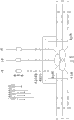
Fig. 1 is wiring diagram of the present invention.
Embodiment
As shown in the figure, step of the present invention is as follows:
1, in the whole secondary loop current situations of current transformer band, with going between, main transformer high-pressure side, medium voltage side and low-pressure side three-phase are connected respectively, stride across transformer, isolating switch, the earthing isolator of high-pressure side disconnector and all the other both sides close, add three-phase current in the high voltage side current mutual inductor side that does not conform to isolating switch, earthing isolator by three-phase current generator, make electric current flow through the current transformer of transformer three sides, the load current situation of three sides when analogue transformer normally moves;
2, detect each side current values, phase place and spill current at main transformer differential protective device place, as spill current=0, each current transformer ratio, polarity and differential circuit wiring are correct; As spill current ≠ 0, each current transformer ratio, polarity and differential circuit wiring are incorrect.
Also can add three-phase current by three-phase current generator at medium voltage side or low-pressure side, method is same as above.
Claims (1)
1. the test method of main transformer current transformer, is characterized in that step is as follows:
(1), in the whole secondary loop current situations of current transformer band, with going between, main transformer high-pressure side, medium voltage side and low-pressure side three-phase are connected respectively, stride across transformer, isolating switch, the earthing isolator of a side disconnector and all the other both sides close, not conforming to isolating switch, earthing isolator one side current transformer side adds three-phase current by three-phase current generator, make electric current flow through the current transformer of transformer three sides, the load current situation of three sides when analogue transformer normally moves;
(2), detect each side current values, phase place and spill current at main transformer differential protective device place,, as spill current=0, each current transformer ratio, polarity and differential circuit wiring are correct; As spill current ≠ 0, each current transformer ratio, polarity and differential circuit wiring are incorrect.
Priority Applications (1)
| Application Number | Priority Date | Filing Date | Title |
|---|---|---|---|
| CN201310628669.0A CN103809146A (en) | 2013-12-02 | 2013-12-02 | Test method of main transformer CT (Current Transformer) |
Applications Claiming Priority (1)
| Application Number | Priority Date | Filing Date | Title |
|---|---|---|---|
| CN201310628669.0A CN103809146A (en) | 2013-12-02 | 2013-12-02 | Test method of main transformer CT (Current Transformer) |
Publications (1)
| Publication Number | Publication Date |
|---|---|
| CN103809146A true CN103809146A (en) | 2014-05-21 |
Family
ID=50706199
Family Applications (1)
| Application Number | Title | Priority Date | Filing Date |
|---|---|---|---|
| CN201310628669.0A Pending CN103809146A (en) | 2013-12-02 | 2013-12-02 | Test method of main transformer CT (Current Transformer) |
Country Status (1)
| Country | Link |
|---|---|
| CN (1) | CN103809146A (en) |
Cited By (4)
| Publication number | Priority date | Publication date | Assignee | Title |
|---|---|---|---|---|
| CN104950203A (en) * | 2015-06-17 | 2015-09-30 | 国网山东潍坊市寒亭区供电公司 | Checking method for current protection circuit of transformer |
| CN109375047A (en) * | 2018-09-25 | 2019-02-22 | 深圳供电局有限公司 | System and method for testing double-end asynchronous polarity of high-voltage transmission line |
| CN110221165A (en) * | 2019-06-11 | 2019-09-10 | 安徽马钢设备检修有限公司 | A kind of motor differential protection test new method |
| CN113376563A (en) * | 2021-06-08 | 2021-09-10 | 中国南方电网有限责任公司超高压输电公司 | Transformer lifting seat structure with current transformer test wire and test method |
Citations (4)
| Publication number | Priority date | Publication date | Assignee | Title |
|---|---|---|---|---|
| JP2001201519A (en) * | 2000-01-17 | 2001-07-27 | Meidensha Corp | Testing device and test method of current measuring circuit |
| CN201319064Y (en) * | 2008-11-10 | 2009-09-30 | 西北电网有限公司 | Test circuit for field accuracy detection of high-voltage current transformer |
| CN102508190A (en) * | 2011-11-03 | 2012-06-20 | 四川电力科学研究院 | Method for testing error influence quantity to high-voltage three-phase current transformer from high-voltage leakage current |
| CN102540001A (en) * | 2012-02-16 | 2012-07-04 | 云南电网公司 | Method of checking alternating current loop of a 500kV transformer substation through carrying out simulated through-type three-phase short circuit |
-
2013
- 2013-12-02 CN CN201310628669.0A patent/CN103809146A/en active Pending
Patent Citations (4)
| Publication number | Priority date | Publication date | Assignee | Title |
|---|---|---|---|---|
| JP2001201519A (en) * | 2000-01-17 | 2001-07-27 | Meidensha Corp | Testing device and test method of current measuring circuit |
| CN201319064Y (en) * | 2008-11-10 | 2009-09-30 | 西北电网有限公司 | Test circuit for field accuracy detection of high-voltage current transformer |
| CN102508190A (en) * | 2011-11-03 | 2012-06-20 | 四川电力科学研究院 | Method for testing error influence quantity to high-voltage three-phase current transformer from high-voltage leakage current |
| CN102540001A (en) * | 2012-02-16 | 2012-07-04 | 云南电网公司 | Method of checking alternating current loop of a 500kV transformer substation through carrying out simulated through-type three-phase short circuit |
Non-Patent Citations (1)
| Title |
|---|
| 周宝忠 等: "改进的电流互感器试验方法", 《东北电力技术》, no. 5, 31 May 2013 (2013-05-31), pages 38 - 40 * |
Cited By (8)
| Publication number | Priority date | Publication date | Assignee | Title |
|---|---|---|---|---|
| CN104950203A (en) * | 2015-06-17 | 2015-09-30 | 国网山东潍坊市寒亭区供电公司 | Checking method for current protection circuit of transformer |
| CN104950203B (en) * | 2015-06-17 | 2017-08-29 | 国网山东潍坊市寒亭区供电公司 | Transformer current protective loop method of calibration |
| CN109375047A (en) * | 2018-09-25 | 2019-02-22 | 深圳供电局有限公司 | System and method for testing double-end asynchronous polarity of high-voltage transmission line |
| CN109375047B (en) * | 2018-09-25 | 2020-10-16 | 深圳供电局有限公司 | System and method for testing double-end asynchronous polarity of high-voltage transmission line |
| CN110221165A (en) * | 2019-06-11 | 2019-09-10 | 安徽马钢设备检修有限公司 | A kind of motor differential protection test new method |
| CN110221165B (en) * | 2019-06-11 | 2021-03-26 | 安徽马钢设备检修有限公司 | Novel motor differential protection test method |
| CN113376563A (en) * | 2021-06-08 | 2021-09-10 | 中国南方电网有限责任公司超高压输电公司 | Transformer lifting seat structure with current transformer test wire and test method |
| CN113376563B (en) * | 2021-06-08 | 2022-08-12 | 中国南方电网有限责任公司超高压输电公司 | Transformer lifting seat structure with current transformer test wire and test method |
Similar Documents
| Publication | Publication Date | Title |
|---|---|---|
| EP3605773B1 (en) | Safe operation method for voltage reduction and arc suppression of ground fault phase of non-effective grounding system | |
| CN103346541B (en) | Convertor station direct current filter differential protection method and device | |
| CN103762554B (en) | Three-phase three-winding transformer divides side winding failure detection method | |
| CN102608485B (en) | Detection method for zero-sequence current loops of transformer substations | |
| CN102565618A (en) | Method for detecting zero-sequence voltage circuit of transformer substation | |
| CN106569075A (en) | Main transformer and high voltage side cable zero-sequence differential protection polarity test circuit and method | |
| CN107300684B (en) | A kind of check method in transformer differential protection secondary circuit | |
| CN103809146A (en) | Test method of main transformer CT (Current Transformer) | |
| CN105785157A (en) | Double main transformer longitudinal differential protection loop closing testing method | |
| CN103389422A (en) | Method for detecting non-fault phase busbar differential protection maloperation cause during circuit reclosing period | |
| CN206208997U (en) | A kind of transforming plant primary flow device | |
| CN204011024U (en) | A kind of novel electronic type zero sequence current transformer | |
| CN104158149A (en) | Intelligent leakage protector provided with broken null line protection function and broken null line protection method | |
| CN103809039A (en) | Method for testing current transformers in substation | |
| CN103048586B (en) | The verification method of voltage transformer (VT) wiring correctness | |
| CN204903715U (en) | Many functional switch power test operation platform | |
| CN105319478A (en) | Un-disassembly polarity and transformation ratio testing method for transformer bushing | |
| CN102565614B (en) | Alternating voltage loop test method | |
| CN107870311A (en) | A kind of detecting system and detection method of series-parallel connection current transformer | |
| CN105974229A (en) | Disconnection-free testing method for high voltage electric equipment in transformer substation | |
| CN103616657A (en) | Method for testing single-interval current transformer | |
| CN202268244U (en) | Current transformer | |
| CN103779836A (en) | Transformer winding fault relay protection method based on ring current mutation feature | |
| CN103207344A (en) | Method used for checking substation secondary current return circuit and based on main transformer short circuit test | |
| CN202651659U (en) | Drainage apparatus capable of replacing isolating switch with load |
Legal Events
| Date | Code | Title | Description |
|---|---|---|---|
| C06 | Publication | ||
| PB01 | Publication | ||
| C10 | Entry into substantive examination | ||
| SE01 | Entry into force of request for substantive examination | ||
| C02 | Deemed withdrawal of patent application after publication (patent law 2001) | ||
| WD01 | Invention patent application deemed withdrawn after publication |
Application publication date: 20140521 |