CN103117493A - Automation mounting equipment for connector outer shell and rubber core - Google Patents
Automation mounting equipment for connector outer shell and rubber core Download PDFInfo
- Publication number
- CN103117493A CN103117493A CN2013100140036A CN201310014003A CN103117493A CN 103117493 A CN103117493 A CN 103117493A CN 2013100140036 A CN2013100140036 A CN 2013100140036A CN 201310014003 A CN201310014003 A CN 201310014003A CN 103117493 A CN103117493 A CN 103117493A
- Authority
- CN
- China
- Prior art keywords
- shell
- glue core
- mentioned
- side pressure
- cylinder
- Prior art date
- Legal status (The legal status is an assumption and is not a legal conclusion. Google has not performed a legal analysis and makes no representation as to the accuracy of the status listed.)
- Granted
Links
Images


Landscapes
- Manufacturing Of Electrical Connectors (AREA)
Abstract
The invention discloses automation mounting equipment for a connector outer shell and a rubber core. The automation mounting equipment for the connector outer shell and the rubber core comprises a machine frame, a feed device, a plug-in matched stack device, an electrical performance testing device and a discharge device, and the feed device, the plug-in matched stack device, the electrical performance testing device and the discharge device are arranged on the machine frame in sequence. Therefore, the feed device, the plug-in matched stack device, the electrical performance testing device and the discharge device are combined in order and form a connector which integrates feed, matched stack and detection. The automation mounting equipment for the connector outer shell and the rubber core achieves rapid and accurate automatic assembly of the connector outer shell and the rubber core, replaces manual assembling, improves production efficiency of the connecter and reduces production cost.
Description
Technical field
The present invention relates to the electric connector field technology, refer in particular to a kind of device for assembly and connection device shell and glue core.
Background technology
electric connector is generally assembled by glue core and shell, so the assembling of electric connector is about to the glue core and shell is assembled according to definite relation between the two, main assembling procedure step comprises: first the glue core is installed in shell, again shell both sides fixing feet and sheath top plate are bent backward to prevent that the glue core is by deviating from shell, at present, electric connector rubber core and shell assembling procedure generally adopt artificial or semi-automatic platform is completed, the relatively various complexity of its operation, exist production efficiency low, the human resources consumption is large, operating personnel's labour intensity is large, the defectives such as the high and electric connector fraction defective height of comparatively safe hidden danger probability.Therefore, for above defective, glue core and the shell mounting equipment of reply electric connector are improved, assembling automation with further raising electric connector, improve production efficiency and product quality reduces the potential safety hazard in production process, reduces the disqualification rate of electric connector.
Summary of the invention
In view of this, the present invention is directed to the disappearance of prior art existence, its main purpose is to provide a kind of connector shell and glue core apparatus automatization assembling, realize that connector shell and glue core assemble fast and accurately automatically, thereby replace assembling manually, improve the production efficiency of connector, reduce production costs.
For achieving the above object, the present invention adopts following technical scheme:
A kind of connector shell and glue core apparatus automatization assembling include frame and the feeding device that sets gradually, grafting device for assembling, electric characteristic detecting apparatus and drawing mechanism on frame, wherein:
this feeding device comprises shell conveying mechanism and glue core conveying mechanism, this shell conveying mechanism involving vibrations dish, shell transport tape and shell are passed assembly, this shell transport tape one end is connected with the discharging opening of vibrating disk, this shell passing assembly includes and pushes away the shell cylinder, shell pushes part and shell sliding seat, be provided with the shell slideway that moves for shell on this shell sliding seat, be provided with the shell entrance that enters for shell on this shell slideway one sidewall, this shell entrance is connected with the shell transport tape, this shell pushes the part front end and is placed in the shell slideway, shell pushes the part rear end and pushes away shell cylinder axle head and be connected, and push in shell that on part, corresponding shell entrance is provided be used to the recess that holds shell, be provided with the breach that shifts out the shell slideway for shell on another sidewall of shell slideway, this breach is connected with above-mentioned grafting device for assembling, this glue core conveying mechanism has a glue core transport tape, and this glue core transport tape other end also is connected with the grafting device for assembling,
Pushing away shell mechanism glue core transport tape should the grafting device for assembling comprise shell travel mechanism, deflector and pushes away the glue core mechanism, wherein this shell travel mechanism comprises transverse shifting section and vertical moving part, this transverse shifting section comprises glide base and is installed on lateral thrust cylinder and sliding shoe on glide base, be provided with cross slide way on this glide base, sliding shoe is slideable to be installed on this cross slide way, this lateral thrust cylinder is installed on glide base, and lateral thrust cylinder axle head is connected with sliding shoe; This vertical moving part comprises sliding panel, vertical thrust cylinder and vertical movable plate, this sliding panel inwall is fixed on above-mentioned sliding shoe, be provided with vertical guide on the sliding panel outer wall, vertical movable plate inwall can slide up and down formula and be installed on this vertical guide, vertical thrust cylinder is installed in the sliding panel top, vertical thrust cylinder axle head is connected with vertical movable plate, and is arranged side by side a plurality of fork-join arms that are useful on transfer enclosure on vertical movable plate outer wall down; This deflector has a guiding gutter that supplies connector to pass through, and is provided with a plurality of breach and of walking and walks passage on this guiding gutter, and wherein, it is corresponding with above-mentioned fork-join arm that this walks breach; This pushes away the glue core mechanism and comprises and push away in advance assembly and compression assemblies, this pushes away in advance assembly and comprises that pre-push cylinder, glue core sliding seat and glue core push part, be provided with the glue core slideway that moves for the glue core on this glue core sliding seat, corresponding above-mentioned glue core transport tape is provided with a glue core entrance for the immigration of glue core on this glue core slideway lateral wall; This glue core pushes part and is placed in glue core slideway, and this glue core pushes the part front end and is provided with a groove that is used for blocking the glue core, and the glue core pushes the part rear end and is connected with above-mentioned pre-push cylinder axle head; This compression assemblies and the above-mentioned assembly that pushes away in advance are arranged side by side, and over against above-mentioned fork-join arm, it comprises that this side press module, top die block and compression module are positioned at above-mentioned deflector homonymy for the side press module of bending shell both sides fixing feet, the compression module that is used for the top die block of bending sheath top plate and is used for qualified after testing connector is done further compression;
This electric characteristic detecting apparatus and above-mentioned shell travel mechanism homonymy, it comprises tested cylinder, test sliding seat, test guide block and test connector, this tested cylinder is installed on the test sliding seat, be provided with the test guide rail on the test sliding seat, above-mentioned test guide block is installed on this test guide rail, and test guide block rear end is connected with the tested cylinder axle head, and above-mentioned test connector is installed in tests the guide block front end;
This drawing mechanism comprises the discharging transport tape and drives the transmission mechanism of discharging transport tape running, and this discharging transport tape is connected with guiding gutter in above-mentioned deflector.
The present invention compared with prior art has obvious advantage and beneficial effect, particularly, as shown from the above technical solution, by with feeding device, grafting device for assembling, electric characteristic detecting apparatus and the orderly combination of drawing mechanism, form connector feed, assembly, detect and go out package integral, realize connector shell and glue core fast and accurately assembling automatically, thereby replace assembling manually, improve the production efficiency of connector, reduce production costs.
For more clearly setting forth architectural feature of the present invention and effect, be described in detail below in conjunction with accompanying drawing and specific embodiment.
Description of drawings
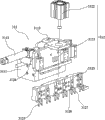
Fig. 1 is the present invention's assembling schematic perspective view;
Fig. 2 is the present invention's exploded perspective schematic diagram;
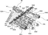
Fig. 3 is the present invention's grafting device for assembling schematic perspective view;
Fig. 4 is another visual angle schematic perspective view of grafting device for assembling of the present invention;
Fig. 5 is shell travel mechanism schematic perspective view outside the present invention;
Fig. 6 is another visual angle schematic perspective view of shell travel mechanism outside the present invention;
Fig. 7 is shell travel mechanism exploded perspective schematic diagram outside the present invention;
Fig. 8 be the present invention push away glue core mechanism and electric characteristic detecting apparatus schematic perspective view;
Fig. 9 be the present invention push away glue core mechanism and another visual angle schematic perspective view of electric characteristic detecting apparatus;
Figure 10 is the present invention's drawing mechanism schematic perspective view;
Figure 11 be the present invention push away in advance the assembly schematic perspective view;
Figure 12 be the present invention push away in advance assembly exploded perspective schematic diagram;
Figure 13 is that outside the present invention, shell is passed the assembly schematic perspective view;
Figure 14 is that outside the present invention, shell is passed assembly exploded perspective schematic diagram.
The accompanying drawing identifier declaration:
10, frame 20, feeding device
21, shell conveying mechanism 211, vibrating disk
212, shell transport tape 213, shell are passed assembly
2131, push away shell cylinder 2132, shell pushes part
2133, shell sliding seat 2134, shell slideway
2135, shell entrance 2136, recess
2137, breach 30, grafting device for assembling
31, shell travel mechanism 311, transverse shifting section
3111, glide base 3112, lateral thrust cylinder
3113, sliding shoe 3114, cross slide way
312, vertical moving part 3121, sliding panel
3122, vertical thrust cylinder 3123, vertical movable plate
3124, vertical guide 3125, fork-join arm
3126, main part 3127, yoke
32, deflector 321, the first baffler
3211, step 3212, stuck-module
3213, the first fixed block 3214, the second fixed block
3215, shed space 3216, through hole
3217, fixture block 322, the second baffler
3221, walk breach 3222, walk passage
323, guiding gutter 33, push away the glue core mechanism
331, push away in advance assembly 3311, pre-push cylinder
3312, glue core sliding seat 3313, glue core push part
3314, glue core slideway 3315, glue core entrance
3316, groove 3317, guide vane end stop
3318, limiting plate 3319, stopper slot
332, compression assemblies 3321, side press module
3322, side pressure track plates 3323, side pressure cylinder
3324, side pressure section 3325, side pressure guide block
3326, side pressure 3327, side pressure guide groove
3328, the first side pressure 3329, arc pressing pin
3330, the second side pressure 3331, square pressing pin
3340, track plates is pressed on top die block 3341, top
3342, guide groove 3343, top air cylinder are pressed in the top
3344, guide block is pressed on top splenium 3345, top
3346, top pressure head 3347, the first top pressure head
3348, wedge shape briquetting 3349, the second top pressure head
3350, arc briquetting 3360, compression module
3361, compress sliding seat 3362, clamping cylinder
3363, compressed part 3364, compression guide block
3365, hold-down head 40, electric characteristic detecting apparatus
41, tested cylinder 42, test sliding seat
421, test guide rail 43, test guide block
44, test connector 50, drawing mechanism
51, discharging transport tape 52, transmission mechanism.
Embodiment
The present invention such as Fig. 1 are extremely shown in Figure 14, a kind of connector shell and glue core apparatus automatization assembling, and the feeding device 20 that includes frame 10 and set gradually on frame 10, grafting device for assembling 30, electric characteristic detecting apparatus 40 and drawing mechanism 50, wherein:
this feeding device 20 comprises shell conveying mechanism 21 and glue core conveying mechanism 22, these shell conveying mechanism 21 involving vibrations dishes 211, shell transport tape 212 and shell are passed assembly 213, these shell transport tape 212 1 ends are connected with the discharging opening of vibrating disk 211, this shell passing assembly 213 includes and pushes away shell cylinder 2131, shell pushes part 2132 and shell sliding seat 2133, be provided with the shell slideway 2134 that moves for shell on this shell sliding seat 2133, be provided with the shell entrance 2135 that enters for shell on these shell slideway 2,134 one sidewalls, this shell entrance 2135 is connected with shell transport tape 212, this shell pushes part 2132 front ends and is placed in shell slideway 2134, shell pushes part 2132 rear ends and pushes away shell cylinder 2131 axle heads and be connected, and push in shell that on part 2132, corresponding shell entrance 2135 is provided be used to the recess 2136 that holds shell, be provided with the breach 2137 that shifts out shell slideway 2134 for shell on shell slideway 2134 another sidewalls, this breach 2137 is connected with above-mentioned grafting device for assembling 30, this glue core conveying mechanism 22 has a glue core transport tape 221, and these glue core transport tape 221 other ends also are connected with grafting device for assembling 30.
push away shell mechanism glue core transport tape and should grafting device for assembling 30 comprise shell travel mechanism 31, deflector 32 and push away glue core mechanism 33, wherein this shell travel mechanism 31 comprises transverse shifting section 311 and vertical moving part 312, this transverse shifting section 311 comprises glide base 3111 and is installed on lateral thrust cylinder 3112 and sliding shoe 3113 on glide base 3111, be provided with cross slide way 3114 on this glide base 3111, sliding shoe 3113 is slideable to be installed on this cross slide way 3114, this lateral thrust cylinder 3112 is installed on glide base 3111, lateral thrust cylinder 3112 axle heads are connected with sliding shoe 3113, this vertical moving part 312 comprises sliding panel 3121, vertical thrust cylinder 3122 and vertical movable plate 3123, these sliding panel 3121 inwalls are fixed on above-mentioned sliding shoe 3113, be provided with vertical guide 3124 on sliding panel 3113 outer walls, vertical movable plate 3123 inwalls can slide up and down formula and be installed on this vertical guide 3124, vertical thrust cylinder 3122 is installed in sliding panel 3121 tops, vertical thrust cylinder 3122 axle heads are connected with vertical movable plate 3123, and be arranged side by side a plurality of fork-join arms 3125 that are useful on transfer enclosure down on vertical movable plate 3123 outer walls, these a plurality of fork-join arm 3125 lower end sidewalls are corresponding with breach on aforementioned shell slideway 2134, this fork-join arm 3125 comprises a main part 3126 and is by this main part 3126 lower ends two yokes 3127 that forked downward one is extended, these yoke 3127 sidewalls are corresponding with breach 2137 on above-mentioned shell slideway 2134,
this deflector 32 comprises the first baffler 321 and the second baffler 322, wherein, this second baffler 322 is fixed on the first baffler 321 sidewalls, and be provided with step 3211 on the first baffler 321, this step 3211 and the second baffler 322 are combined to form the guiding gutter 323 that passes through for connector, be provided with a plurality of breach 3221 and of walking and walk passage 3222 on this second baffler 322, and corresponding above-mentioned a plurality of fork-join arms 3125 are respectively arranged with stuck-module 3212 for fixed connector on above-mentioned the first baffler 321, this stuck-module 3212 comprises the first fixed block 3213 and the second fixed block 3214 that is the L shape, these the first fixed block 3,213 one ends are close on the first baffler 321 lateral walls, its other end puts in above-mentioned guiding gutter 323 and forms shed space 3215 with guiding gutter 323, and be provided with a through hole 3216 in the first fixed block 3213 upper ends, this second fixed block 3214 is installed on the first fixed block 3213 tops, on this first fixed block 3213 to being arranged with a fixture block 3217, this fixture block 3217 puts in above-mentioned shed space 3215 to be in clamping connection device by through hole 3216 on the first fixed block 3213, and this to walk breach 3221 corresponding with above-mentioned fork-join arm 3125,
this pushes away glue core mechanism 33 and comprises and push away in advance assembly 331 and compression assemblies 332, this pushes away in advance assembly 331 and comprises that pre-push cylinder 3311, glue core sliding seat 3312 and glue core push part 3313, be provided with the glue core slideway 3314 that moves for the glue core on this glue core sliding seat 3312, corresponding above-mentioned glue core transport tape 221 is provided with a glue core entrance 3315 for the immigration of glue core on these glue core slideway 3314 lateral walls, this glue core pushes part 3313 and is placed in glue core slideway 3314, this glue core pushes part 3313 front ends and is provided with one for the groove 3316 that blocks the glue core, the glue core pushes part 3313 rear ends and is connected with above-mentioned pre-push cylinder 3311 axle heads, pushing part 3313 tops in this glue core is provided with one and prevents from pushing the guide vane end stop 3317 that part 3313 skids off preset distance, be stamped a limiting plate 3318 in glue core slideway 3314 tops, and offer the stopper slot 3319 that is complementary with guide vane end stop 3317 on limiting plate 3318, limiting plate 3318 pushes part 3313 with the glue core and moves forward, and final supporting terminates in stopper slot 3319, this compression assemblies 332 is arranged side by side with the above-mentioned assembly 331 that pushes away in advance, and over against above-mentioned fork-join arm 3125, it comprises the side press module 3321 for bending shell both sides fixing feet, the compression module 3360 that is used for bending the top die block 3340 of sheath top plate and is used for qualified after testing connector is done further compression, this side press module 3321, top die block 3340 and compression module 3360 are positioned at above-mentioned deflector 32 homonymies, wherein, this side press module 3321 comprises side pressure track plates 3322, side pressure cylinder 3323 and side pressure section 3324, this side pressure section 3324 comprises side pressure guide block 3325 and side pressure 3326, be provided with side pressure guide groove 3327 on this side pressure track plates 3322, this side pressure guide block 3325 is installed in side pressure guide groove 3327, side pressure cylinder 3323 axle heads are connected in side pressure guide block 3325 rear ends, side pressure guide block 3325 moves forward and backward in side pressure guide groove 3327 with cylinder axis, this side pressure 3326 comprises the first side pressure the 3328 and second side pressure 3329, this first side pressure the 3328 and second side pressure 3329 is installed in respectively side pressure guide block 3325 front ends, and two adjacent breach 3221 of walking on corresponding above-mentioned the second baffler 322 respectively, this first side pressure 3328 front end indent backward have an arc notch, this arc notch two ends form respectively an arc pressing pin 3329 with transition arc, between this two pressings pin, distance is slightly larger than the width of shell, this two arcs pressing pin 3329 under the promotion of side pressure cylinder 3323 gradually with lateral buckling in the fixing feet phase shell of shell both sides, the fixing feet that the corresponding shell of this second side pressure 3330 front ends both sides have bent is provided with two square pressing pin 3331, this two square pressing pin 3331 further compresses shell both sides fixing feet under the promotion of side pressure cylinder 3323 to the shell inboard, its bending is put in place, this top die block 3340 comprises top pressure track plates 3341, top air cylinder 3343 and top splenium 3344, this top splenium 3344 comprises top pressure guide block 3345 and top pressure head 3346, this top is pressed and is provided with top pressure guide groove 3342 on track plates 3341, this top is pressed guide block 3345 to be installed on the top and is pressed in guide groove 3342, air cylinder 3343 axle heads in top are connected in pressure guide block 3345 rear ends, top, the top is pressed guide block 3345 to press in guide groove 3342 in the top with cylinder axis and is moved forward and backward, this top pressure head 3346 comprises the first top pressure head 3347 and the second top pressure head 3349, this the first top pressure head 3346 and the second top pressure head 3349 are installed in respectively the top and press guide block 3345 front ends, and two adjacent breach 3221 of walking wherein on corresponding above-mentioned the second baffler 322 respectively, these the first top pressure head 3346 front ends are provided with a wedge shape briquetting 3348, this wedge shape briquetting 3348 can be with bend the downwards top board of shell of the promotion of top air cylinder 3343, make top board bend certain angle downwards, these the second top pressure head 3349 front ends are provided with an arc briquetting 3350 with lower arcs of recesses, this the second top pressure head 3349 is under the promotion of top air cylinder 3343, on it, arc briquetting 3350 will bend the further bending downwards of sheath top plate of certain angle gradually, this compression module 3360 includes one and has the compression sliding seat 3361 that compresses guide groove, clamping cylinder 3362 and compressed part 3363, this compressed part 3363 comprises compression guide block 3364 and hold-down head 3365, slideable being installed on of this compression guide block 3364 compresses on guide groove, compress guide block 3365 front ends and put in above-mentioned walking in passage 3222, compression guide block 3364 rear ends are connected with clamping cylinder 3362 axle heads, this hold-down head 3365 is installed on and compresses guide block 3364 front ends, these hold-down head 3365 front ends are concaved with a step downwards, hold-down head 3365 is under clamping cylinder 3362 promotes, it is topped bar and can further compress the above-mentioned top board that has bent, top board is thoroughly compressed.
This electric characteristic detecting apparatus 40 and above-mentioned shell travel mechanism 31 homonymies, it comprises tested cylinder 41, test sliding seat 42, test guide block 43 and test connector 44, this tested cylinder 41 is installed on test sliding seat 42, be provided with test guide rail 421 on test sliding seat 42, above-mentioned test guide block 43 is installed on this test guide rail 421, and test guide block 43 rear ends are connected with tested cylinder 41 axle heads, and above-mentioned test connector 44 is installed in tests guide block 43 front ends.
This drawing mechanism 50 comprises discharging transport tape 51 and drives the transmission mechanism 52 of discharging transport tape 51 runnings, and this discharging transport tape 51 is connected with guiding gutter 323 in above-mentioned deflector 32.
operation principle of the present invention is as follows: the shell in vibrating disk 211 enters shell entrance 2135 by shell transport tape 212 under the vibration of vibrating disk 211, being embedded in shell pushes on part 2132 in recess 2136, pushing away shell cylinder 2131 promotes shells and pushes part 2132 and move forward in shell slideway 2134, make shell be positioned on shell slideway 2134 breach 2137 places, simultaneously, the glue core is moved to glue core entrance 3315 places that push away on glue core mechanism 33 through glue core transport tape 221 by bonder terminal apparatus automatization assembling discharging opening, at this moment, 31 actions of shell travel mechanism, vertical thrust cylinder 3122 in vertical moving part 312 moves up and drives fork-join arm 3125 and move up, lateral thrust cylinder 3112 in transverse shifting section 311 drives vertical moving part 312 and is moved to the left, fork-join arm 3125 is moved to the left thereupon, leftmost first fork-join arm 3125 is positioned at above shell, again starting vertical thrust cylinder 3122 moves down fork-join arm 3125, clamp shell, again starting lateral thrust cylinder 3112 makes fork-join arm 3125 that shell is moved on deflector 32 first to walk breach 3221 places, pushing away glue core mechanism 33 promotes the glue core forward until the glue core is positioned at enclosure, then, repeat the step of above-mentioned mobile shell, the shell that the glue core has been installed is moved on deflector 32 second, walk breach 3221 places for three, by above-mentioned side press module 3321 with the fixing feet of shell both sides to the shell inner bending, then, the shell that the glue core has been installed is moved on deflector 32 the 4th, walk breach 3221 places for five, by above-mentioned top die block 3340 with sheath top plate to the shell inner bending, at this moment, the glue core has been fixed in shell, electric characteristic detecting apparatus 40 starts, connector is carried out electrical detection, qualified product will be moved to compression module 3360 places, 3362 pairs of sheath top plate of clamping cylinder are carried out and are again compressed, with thorough compression, at last, shell and glue core through thoroughly compressing are transported to next link by drawing mechanism 50.
Design focal point of the present invention is, by with feeding device, grafting device for assembling, electric characteristic detecting apparatus and the orderly combination of drawing mechanism, form connector feed, assembly, detect and go out package integral, realize that connector shell and glue core assemble fast and accurately automatically, thereby replace assembling manually, improve the production efficiency of connector, reduce production costs.
The above, it is only preferred embodiment of the present invention, be not that technical scope of the present invention is imposed any restrictions, therefore every foundation technical spirit of the present invention all still belongs in the scope of technical solution of the present invention any trickle modification made for any of the above embodiments, equivalent variations and modification.
Claims (10)
1. a connector shell and glue core apparatus automatization assembling is characterized in that: include frame and the feeding device that sets gradually, grafting device for assembling, electric characteristic detecting apparatus and drawing mechanism on frame, wherein:
this feeding device comprises shell conveying mechanism and glue core conveying mechanism, this shell conveying mechanism involving vibrations dish, shell transport tape and shell are passed assembly, this shell transport tape one end is connected with the discharging opening of vibrating disk, this shell passing assembly includes and pushes away the shell cylinder, shell pushes part and shell sliding seat, be provided with the shell slideway that moves for shell on this shell sliding seat, be provided with the shell entrance that enters for shell on this shell slideway one sidewall, this shell entrance is connected with the shell transport tape, this shell pushes the part front end and is placed in the shell slideway, shell pushes the part rear end and pushes away shell cylinder axle head and be connected, and push in shell that on part, corresponding shell entrance is provided be used to the recess that holds shell, be provided with the breach that shifts out the shell slideway for shell on another sidewall of shell slideway, this breach is connected with above-mentioned grafting device for assembling, this glue core conveying mechanism has a glue core transport tape, and this glue core transport tape other end also is connected with the grafting device for assembling,
This grafting device for assembling comprises shell travel mechanism, deflector and pushes away the glue core mechanism, wherein this shell travel mechanism comprises transverse shifting section and vertical moving part, this transverse shifting section comprises glide base and is installed on lateral thrust cylinder and sliding shoe on glide base, be provided with cross slide way on this glide base, sliding shoe is slideable to be installed on this cross slide way, this lateral thrust cylinder is installed on glide base, and lateral thrust cylinder axle head is connected with sliding shoe; This vertical moving part comprises sliding panel, vertical thrust cylinder and vertical movable plate, this sliding panel inwall is fixed on above-mentioned sliding shoe, be provided with vertical guide on the sliding panel outer wall, vertical movable plate inwall can slide up and down formula and be installed on this vertical guide, vertical thrust cylinder is installed in the sliding panel top, vertical thrust cylinder axle head is connected with vertical movable plate, and is arranged side by side a plurality of fork-join arms that are useful on transfer enclosure on vertical movable plate outer wall down; This deflector has a guiding gutter that supplies connector to pass through, and is provided with a plurality of breach and of walking and walks passage on this guiding gutter, and wherein, it is corresponding with above-mentioned fork-join arm that this walks breach; This pushes away the glue core mechanism and comprises and push away in advance assembly and compression assemblies, this pushes away in advance assembly and comprises that pre-push cylinder, glue core sliding seat and glue core push part, be provided with the glue core slideway that moves for the glue core on this glue core sliding seat, corresponding above-mentioned glue core transport tape is provided with a glue core entrance for the immigration of glue core on this glue core slideway lateral wall; This glue core pushes part and is placed in glue core slideway, and this glue core pushes the part front end and is provided with a groove that is used for blocking the glue core, and the glue core pushes the part rear end and is connected with above-mentioned pre-push cylinder axle head; This compression assemblies and the above-mentioned assembly that pushes away in advance are arranged side by side, and over against above-mentioned fork-join arm, it comprises that this side press module, top die block and compression module are positioned at above-mentioned deflector homonymy for the side press module of bending shell both sides fixing feet, the compression module that is used for the top die block of bending sheath top plate and is used for qualified after testing connector is done further compression;
This electric characteristic detecting apparatus and above-mentioned shell travel mechanism homonymy, it comprises tested cylinder, test sliding seat, test guide block and test connector, this tested cylinder is installed on the test sliding seat, be provided with the test guide rail on the test sliding seat, above-mentioned test guide block is installed on this test guide rail, and test guide block rear end is connected with the tested cylinder axle head, and above-mentioned test connector is installed in tests the guide block front end;
This drawing mechanism comprises the discharging transport tape and drives the transmission mechanism of discharging transport tape running, and this discharging transport tape is connected with guiding gutter in above-mentioned deflector.
2. connector shell and glue core apparatus automatization assembling according to claim 1, it is characterized in that: described deflector comprises the first baffler and the second baffler, wherein, this second baffler is fixed on the first baffler sidewall, be provided with step on the first baffler, this step and the second baffler are combined to form above-mentioned guiding gutter.
3. connector shell and glue core apparatus automatization assembling according to claim 2 is characterized in that: described walk breach and walk passage be arranged side by side on above-mentioned the second baffler.
4. connector shell and glue core apparatus automatization assembling according to claim 1, it is characterized in that: described fork-join arm comprises a main part and is by this main part lower end two yokes that forked downward one is extended, and this yoke sidewall is corresponding with breach on above-mentioned shell slideway.
5. connector shell and glue core apparatus automatization assembling according to claim 2, it is characterized in that: on described the first baffler, corresponding above-mentioned a plurality of fork-join arms are respectively arranged with the stuck-module for fixed connector, this stuck-module comprises the first fixed block and the second fixed block that is the L shape, this the first fixed block one end is close on the first baffler lateral wall, its other end puts in above-mentioned guiding gutter with guiding gutter and forms the shed space, and is provided with a through hole in the first fixed block upper end; This second fixed block is installed on above the first fixed block, and to being arranged with a fixture block, this fixture block is put in above-mentioned shed space to be in clamping connection device by through hole on the first fixed block on this first fixed block.
6. connector shell and glue core apparatus automatization assembling according to claim 1, it is characterized in that: described glue core pushes the part top and is provided with a pair of glue core and pushes the part spacing guide vane end stop that slides, be covered with a limiting plate above above-mentioned glue core slideway, corresponding above-mentioned guide vane end stop is provided with stopper slot on this limiting plate, and the guide vane end stop upper end is arranged in this stopper slot.
7. connector shell and glue core apparatus automatization assembling according to claim 1, it is characterized in that: described side press module comprises side pressure track plates, side pressure cylinder and side pressure section, this side pressure cylinder is installed on the side pressure track plates, be provided with the side pressure guide groove on the side pressure track plates, slideable being installed in this side pressure guide groove of above-mentioned side pressure section, side pressure cylinder axle head is connected with side pressure section rear end;
Described top die block comprises top pressure track plates, top air cylinder and top splenium, this top air cylinder is installed on the top and presses on track plates, press in the top and be provided with top pressure guide groove on track plates, above-mentioned top splenium is slideable to be installed in this top pressure guide groove, and top air cylinder axle head is connected with splenium rear end, top;
Described compression module comprises compression sliding seat, clamping cylinder and compressed part, this clamping cylinder is installed on and compresses on sliding seat, be provided with the compression guide groove in compressing on sliding seat, above-mentioned compressed part is slideable to be installed in this compression guide groove, and the clamping cylinder axle head is connected with the compressed part rear end.
8. connector shell and glue core apparatus automatization assembling according to claim 7, it is characterized in that: described side pressure section comprises side pressure guide block and side pressure head, wherein, this side pressure guide block is installed in above-mentioned side pressure guide groove, and side pressure guide block rear end is connected with above-mentioned side pressure cylinder axle head, this side pressure head comprises the first side pressure head and the second side pressure head, this the first side pressure head and the second side pressure head are installed in respectively side pressure guide block front end, and two adjacent breach of walking on corresponding above-mentioned the second baffler respectively, this the first side pressure front end indent backward is formed with an arc notch, this arc notch two ends form respectively an arc pressing pin with transition arc, between this two pressings pin, distance is greater than outer casing width, when the side pressure cylinder promotes, it is crooked in the shell that this two arcs pressing pin promotes shell both sides fixing feet gradually, this the second side pressure front end is provided with two square pressing pin, when the side pressure cylinder promotes, this two square pressing pin further promotes shell both sides fixing feet to the shell inside bend.
9. connector shell and glue core apparatus automatization assembling according to claim 7, it is characterized in that: described top splenium comprises top pressure guide block and top pressure head, this top is pressed guide block to be installed on above-mentioned top and is pressed in guide groove, pressure guide block rear end, top is connected with above-mentioned top air cylinder axle head, this top pressure head comprises the first top pressure head and the second top pressure head, this the first top pressure head and the second top pressure head are installed in respectively the top and press the guide block front end, and two adjacent breach of walking wherein on corresponding above-mentioned the second baffler respectively, this the first top pressure head front end is provided with a wedge shape briquetting, when the top air cylinder promotes, the wedge shape briquetting pushes forward, sheath top plate is bending downwards thereupon, this the second top pressure head front end is provided with an arc briquetting with recessed deep-slotted chip breaker, when the top air cylinder promotes, this arc briquetting is pushed downwards, bent the further bending downwards of sheath top plate of certain angle.
10. connector shell and glue core apparatus automatization assembling according to claim 7, it is characterized in that: described compressed part includes and compresses guide block and hold-down head, this compression guide block is installed in above-mentioned compression guide groove, compress the guide block front end and put in walking in passage on above-mentioned deflector, compression guide block rear end is connected with the clamping cylinder axle head, this hold-down head is installed on and compresses the guide block front end, this hold-down head front end is concaved with a step downwards, when clamping cylinder promotes, this step compresses forward, and sheath top plate is drawn close with side wall of outer shell thereupon.
Priority Applications (1)
| Application Number | Priority Date | Filing Date | Title |
|---|---|---|---|
| CN201310014003.6A CN103117493B (en) | 2013-01-15 | 2013-01-15 | Automation mounting equipment for connector outer shell and rubber core |
Applications Claiming Priority (1)
| Application Number | Priority Date | Filing Date | Title |
|---|---|---|---|
| CN201310014003.6A CN103117493B (en) | 2013-01-15 | 2013-01-15 | Automation mounting equipment for connector outer shell and rubber core |
Publications (2)
| Publication Number | Publication Date |
|---|---|
| CN103117493A true CN103117493A (en) | 2013-05-22 |
| CN103117493B CN103117493B (en) | 2015-01-28 |
Family
ID=48415800
Family Applications (1)
| Application Number | Title | Priority Date | Filing Date |
|---|---|---|---|
| CN201310014003.6A Expired - Fee Related CN103117493B (en) | 2013-01-15 | 2013-01-15 | Automation mounting equipment for connector outer shell and rubber core |
Country Status (1)
| Country | Link |
|---|---|
| CN (1) | CN103117493B (en) |
Cited By (16)
| Publication number | Priority date | Publication date | Assignee | Title |
|---|---|---|---|---|
| CN103317342A (en) * | 2013-05-29 | 2013-09-25 | 东莞市津达电子有限公司 | Automatic assembling machine for patch type connector |
| CN103794967A (en) * | 2014-03-20 | 2014-05-14 | 苏州源硕精密模具有限公司 | Automatic row insertion machine |
| CN103855592A (en) * | 2014-02-19 | 2014-06-11 | 东莞市凯昶德电子科技股份有限公司 | HDMI-CF electric coupler automatic assembling machine |
| CN104158047A (en) * | 2014-08-22 | 2014-11-19 | 苏州昌飞自动化设备厂 | Double-lug connection sheet automatic feed assembling mechanism of double-lug flat cable copper joint assembling machine |
| CN104733975A (en) * | 2015-01-30 | 2015-06-24 | 上海昭程整流子科技有限公司 | Uncovering and shelling machine |
| CN106329269A (en) * | 2016-09-02 | 2017-01-11 | 苏州新亚电通有限公司 | Automatic production and detection apparatus of connectors for flexible circuits |
| CN106785799A (en) * | 2017-01-25 | 2017-05-31 | 东莞磁威电子科技有限公司 | A kind of LED assembling testing equipments of connector |
| CN107171161A (en) * | 2017-06-30 | 2017-09-15 | 天津市华之阳特种线缆有限公司 | A kind of hand Wiring harness terminal, plastic kludge |
| CN108173104A (en) * | 2017-12-26 | 2018-06-15 | 嵊州领航信息科技有限公司 | A kind of interface apparatus automatization assembling |
| CN108963717A (en) * | 2018-08-20 | 2018-12-07 | 温州正泰电源电器有限公司 | A kind of automatic assembling machine of transformer connecting terminal |
| CN109204940A (en) * | 2018-08-06 | 2019-01-15 | 胡彬 | Lithium battery processing and packing device |
| CN109830867A (en) * | 2019-01-31 | 2019-05-31 | 李琼 | A kind of the matrix decentralized institution and dispersing method of the first-born production of charging connection |
| CN110197968A (en) * | 2019-06-12 | 2019-09-03 | 安费诺奥罗拉科技(惠州)有限公司 | A kind of connector and its assembling equipment |
| CN110838663A (en) * | 2019-11-25 | 2020-02-25 | 东莞市邦泰自动化科技有限公司 | High-speed backplane connector assembling machine |
| CN110994330A (en) * | 2019-12-06 | 2020-04-10 | 苏州新亚电通有限公司 | Rubber core and terminal assembling device of connector |
| CN111438501A (en) * | 2020-04-07 | 2020-07-24 | 宇山自动化技术(深圳)有限公司 | Automatic assembling and detecting equipment for wiring harness connector |
Citations (12)
| Publication number | Priority date | Publication date | Assignee | Title |
|---|---|---|---|---|
| US4055889A (en) * | 1976-02-18 | 1977-11-01 | Molex Incorporated | Connector harness assembly machine |
| US5598628A (en) * | 1994-10-07 | 1997-02-04 | Yazaki Corporation | Terminal insertion device and an inserting method thereof |
| JPH09145768A (en) * | 1995-11-24 | 1997-06-06 | Sumitomo Wiring Syst Ltd | Inspection equipment |
| CN1790840A (en) * | 2005-12-14 | 2006-06-21 | 赵阿义 | Connector pin insertion machine plastic part delivery mechanism |
| CN201025662Y (en) * | 2007-02-13 | 2008-02-20 | 唐仕文 | Direction detection and control device for automatic connector assembler |
| CN101257175A (en) * | 2008-04-23 | 2008-09-03 | 金洋电子(深圳)有限公司 | Automatic assembling machine of accurate connector |
| CN201565778U (en) * | 2009-11-24 | 2010-09-01 | 富港电子(东莞)有限公司 | Metal casing cutting and inserting machine |
| CN201594686U (en) * | 2009-11-28 | 2010-09-29 | 富港电子(东莞)有限公司 | Connector cover assembling mechanism |
| CN101888051A (en) * | 2010-06-09 | 2010-11-17 | 实盈电子(东莞)有限公司 | Automatic production and assembly method of internal memory connector |
| CN201699304U (en) * | 2010-06-12 | 2011-01-05 | 惠州市利元亨精密自动化有限公司 | Automatic connector assembling machine |
| CN201741975U (en) * | 2010-03-31 | 2011-02-09 | 中航光电科技股份有限公司 | Automatic assembly machine for electrical connector |
| CN203103729U (en) * | 2013-01-15 | 2013-07-31 | 东莞市凯昶德电子科技股份有限公司 | Connector casing/rubber core automated assembly device |
-
2013
- 2013-01-15 CN CN201310014003.6A patent/CN103117493B/en not_active Expired - Fee Related
Patent Citations (12)
| Publication number | Priority date | Publication date | Assignee | Title |
|---|---|---|---|---|
| US4055889A (en) * | 1976-02-18 | 1977-11-01 | Molex Incorporated | Connector harness assembly machine |
| US5598628A (en) * | 1994-10-07 | 1997-02-04 | Yazaki Corporation | Terminal insertion device and an inserting method thereof |
| JPH09145768A (en) * | 1995-11-24 | 1997-06-06 | Sumitomo Wiring Syst Ltd | Inspection equipment |
| CN1790840A (en) * | 2005-12-14 | 2006-06-21 | 赵阿义 | Connector pin insertion machine plastic part delivery mechanism |
| CN201025662Y (en) * | 2007-02-13 | 2008-02-20 | 唐仕文 | Direction detection and control device for automatic connector assembler |
| CN101257175A (en) * | 2008-04-23 | 2008-09-03 | 金洋电子(深圳)有限公司 | Automatic assembling machine of accurate connector |
| CN201565778U (en) * | 2009-11-24 | 2010-09-01 | 富港电子(东莞)有限公司 | Metal casing cutting and inserting machine |
| CN201594686U (en) * | 2009-11-28 | 2010-09-29 | 富港电子(东莞)有限公司 | Connector cover assembling mechanism |
| CN201741975U (en) * | 2010-03-31 | 2011-02-09 | 中航光电科技股份有限公司 | Automatic assembly machine for electrical connector |
| CN101888051A (en) * | 2010-06-09 | 2010-11-17 | 实盈电子(东莞)有限公司 | Automatic production and assembly method of internal memory connector |
| CN201699304U (en) * | 2010-06-12 | 2011-01-05 | 惠州市利元亨精密自动化有限公司 | Automatic connector assembling machine |
| CN203103729U (en) * | 2013-01-15 | 2013-07-31 | 东莞市凯昶德电子科技股份有限公司 | Connector casing/rubber core automated assembly device |
Cited By (26)
| Publication number | Priority date | Publication date | Assignee | Title |
|---|---|---|---|---|
| CN103317342B (en) * | 2013-05-29 | 2016-01-20 | 东莞市津达电子有限公司 | SMD automatic connector assembling machine |
| CN103317342A (en) * | 2013-05-29 | 2013-09-25 | 东莞市津达电子有限公司 | Automatic assembling machine for patch type connector |
| CN103855592A (en) * | 2014-02-19 | 2014-06-11 | 东莞市凯昶德电子科技股份有限公司 | HDMI-CF electric coupler automatic assembling machine |
| CN103855592B (en) * | 2014-02-19 | 2016-06-08 | 东莞市凯昶德电子科技股份有限公司 | A kind of HDMI-CF electric connector automatic assembling |
| CN103794967A (en) * | 2014-03-20 | 2014-05-14 | 苏州源硕精密模具有限公司 | Automatic row insertion machine |
| CN104158047A (en) * | 2014-08-22 | 2014-11-19 | 苏州昌飞自动化设备厂 | Double-lug connection sheet automatic feed assembling mechanism of double-lug flat cable copper joint assembling machine |
| CN104733975A (en) * | 2015-01-30 | 2015-06-24 | 上海昭程整流子科技有限公司 | Uncovering and shelling machine |
| CN106329269A (en) * | 2016-09-02 | 2017-01-11 | 苏州新亚电通有限公司 | Automatic production and detection apparatus of connectors for flexible circuits |
| CN106785799A (en) * | 2017-01-25 | 2017-05-31 | 东莞磁威电子科技有限公司 | A kind of LED assembling testing equipments of connector |
| CN106785799B (en) * | 2017-01-25 | 2023-03-31 | 东莞磁威电子科技有限公司 | LED equipment check out test set of connector |
| CN107171161A (en) * | 2017-06-30 | 2017-09-15 | 天津市华之阳特种线缆有限公司 | A kind of hand Wiring harness terminal, plastic kludge |
| CN108173104A (en) * | 2017-12-26 | 2018-06-15 | 嵊州领航信息科技有限公司 | A kind of interface apparatus automatization assembling |
| CN108173104B (en) * | 2017-12-26 | 2019-08-16 | 嵊州领航信息科技有限公司 | A kind of interface apparatus automatization assembling |
| CN109204940A (en) * | 2018-08-06 | 2019-01-15 | 胡彬 | Lithium battery processing and packing device |
| CN108963717A (en) * | 2018-08-20 | 2018-12-07 | 温州正泰电源电器有限公司 | A kind of automatic assembling machine of transformer connecting terminal |
| CN108963717B (en) * | 2018-08-20 | 2023-09-19 | 温州正泰电源电器有限公司 | Automatic assembly machine for transformer wiring terminals |
| CN109830867A (en) * | 2019-01-31 | 2019-05-31 | 李琼 | A kind of the matrix decentralized institution and dispersing method of the first-born production of charging connection |
| CN109830867B (en) * | 2019-01-31 | 2020-07-31 | 刘新华 | Matrix dispersing mechanism and dispersing method for production of charging connector |
| CN110197968A (en) * | 2019-06-12 | 2019-09-03 | 安费诺奥罗拉科技(惠州)有限公司 | A kind of connector and its assembling equipment |
| CN110197968B (en) * | 2019-06-12 | 2024-03-12 | 安费诺奥罗拉科技(惠州)有限公司 | Connector and assembly equipment thereof |
| CN110838663A (en) * | 2019-11-25 | 2020-02-25 | 东莞市邦泰自动化科技有限公司 | High-speed backplane connector assembling machine |
| CN110838663B (en) * | 2019-11-25 | 2021-04-20 | 东莞市邦泰自动化科技有限公司 | High-speed backplane connector assembling machine |
| CN110994330A (en) * | 2019-12-06 | 2020-04-10 | 苏州新亚电通有限公司 | Rubber core and terminal assembling device of connector |
| CN110994330B (en) * | 2019-12-06 | 2021-07-06 | 苏州新亚电通有限公司 | Rubber core and terminal assembling device of connector |
| CN111438501A (en) * | 2020-04-07 | 2020-07-24 | 宇山自动化技术(深圳)有限公司 | Automatic assembling and detecting equipment for wiring harness connector |
| CN111438501B (en) * | 2020-04-07 | 2021-10-08 | 宇山自动化技术(深圳)有限公司 | Automatic assembling and detecting equipment for wiring harness connector |
Also Published As
| Publication number | Publication date |
|---|---|
| CN103117493B (en) | 2015-01-28 |
Similar Documents
| Publication | Publication Date | Title |
|---|---|---|
| CN103117493B (en) | Automation mounting equipment for connector outer shell and rubber core | |
| CN203103729U (en) | Connector casing/rubber core automated assembly device | |
| CN103117492A (en) | Connector assembling and detecting production line | |
| CN110350377A (en) | A kind of full-automatic compression bonding apparatus of Wiring harness terminal | |
| CN109428253A (en) | USB female assembly machine | |
| CN109130218B (en) | Step-by-step press-in jig for bending terminal | |
| CN113555753B (en) | Radio frequency connector assembly tool | |
| CN203733670U (en) | Automatic assembly equipment for electric torch switch | |
| CN117254328B (en) | Automatic connector assembling equipment | |
| CN103406753B (en) | Heat radiation module automatic buckling equipment | |
| CN116365381A (en) | Outdoor waterproof communication equipment electric power cabinet | |
| CN206123123U (en) | Capping device is inserted to pin faller gill | |
| CN213043145U (en) | Electric connector plugging mechanism | |
| CN212526425U (en) | Reflow soldering equipment connecting plate | |
| CN103691942B (en) | Full-automatic silver alloy contact re-pressing machine | |
| CN219892582U (en) | Connector discharging device | |
| CN207082708U (en) | DTU line loss terminal current automatic crimping structures | |
| CN220323379U (en) | Chip box socket detection device | |
| CN219488749U (en) | Automatic closed loop positioning assembly | |
| CN115331890B (en) | Device for separating wires and pressing waves of electronic detonator | |
| CN109530599A (en) | A kind of automatic riveting lamp nail method | |
| CN215452001U (en) | Improved structure of terminal crimping equipment | |
| CN114583524B (en) | Riveting device for upper die hard stripping terminal | |
| CN220673058U (en) | Crown spring assembling equipment with necking mechanism | |
| CN116887550B (en) | Electric power load management terminal casing package assembly |
Legal Events
| Date | Code | Title | Description |
|---|---|---|---|
| C06 | Publication | ||
| PB01 | Publication | ||
| C10 | Entry into substantive examination | ||
| SE01 | Entry into force of request for substantive examination | ||
| C14 | Grant of patent or utility model | ||
| GR01 | Patent grant | ||
| CF01 | Termination of patent right due to non-payment of annual fee | ||
| CF01 | Termination of patent right due to non-payment of annual fee |
Granted publication date: 20150128 Termination date: 20190115 |