CN102976123A - Feeding mechanism of chamfering device - Google Patents
Feeding mechanism of chamfering device Download PDFInfo
- Publication number
- CN102976123A CN102976123A CN2012104956833A CN201210495683A CN102976123A CN 102976123 A CN102976123 A CN 102976123A CN 2012104956833 A CN2012104956833 A CN 2012104956833A CN 201210495683 A CN201210495683 A CN 201210495683A CN 102976123 A CN102976123 A CN 102976123A
- Authority
- CN
- China
- Prior art keywords
- material box
- supporting plate
- rotating
- ball screw
- motor
- Prior art date
- Legal status (The legal status is an assumption and is not a legal conclusion. Google has not performed a legal analysis and makes no representation as to the accuracy of the status listed.)
- Granted
Links
Images

Landscapes
- Container, Conveyance, Adherence, Positioning, Of Wafer (AREA)
Abstract
本发明提供一种倒角设备的送料机构,包括料盒、托板、旋转托架、旋转电机、导杆、升降台、滚珠丝杠、步进电机和光纤式光电感应开关,所述料盒有四个,均位于所述托板上,所述料盒上设有所述光纤式光电感应开关,所述托板下设有所述旋转托架和旋转电机,所述旋转托架与所述旋转电机相连;所述托板下还设有三根所述导杆,所述导杆下端均固定在所述升降台上,所述升降台与所述滚珠丝杠通过滚珠螺母连接,所述滚珠丝杠与所述步进电机相连。本发明的有益效果是提高了设备精度、设备自动化程度,达到提高生产效率、降低人工成本的目的。
The invention provides a feeding mechanism of chamfering equipment, which includes a material box, a pallet, a rotating bracket, a rotating motor, a guide rod, a lifting table, a ball screw, a stepping motor, and an optical fiber photoelectric sensor switch. There are four, all located on the supporting plate, the optical fiber photoelectric sensor switch is arranged on the material box, the rotating bracket and the rotating motor are arranged under the supporting plate, and the rotating bracket and the rotating The rotating motor is connected; the supporting plate is also provided with three guide rods, the lower ends of the guide rods are all fixed on the lifting platform, and the lifting platform is connected with the ball screw through a ball nut. The ball screw is connected with the stepping motor. The invention has the beneficial effects of improving equipment precision and equipment automation, achieving the goals of improving production efficiency and reducing labor costs.
Description
技术领域technical field
本发明属于半导体材料生产技术领域,尤其是涉及一种倒角设备的送料机构。The invention belongs to the technical field of semiconductor material production, and in particular relates to a feeding mechanism of chamfering equipment.
背景技术Background technique
半导体材料的加工都需要用到倒角设备,现有的技术中倒角设备的送料机构一般均采用单盒送料方式,料盒内的硅片送到输送带的方法是:料盒下降一个间距,间距大小与料盒每层间距有关,提前测量出来,把数据输入触摸屏;电容式接近开关检测确认硅片是否到位,如果未到位,则再下降一个间距,如果到位,输送带运转,将硅片送出。该上料方式存在以下问题:硅片送到输送带上的精度较低,其原因有:精度受硅片盒层间距的影响、受片盒外形尺寸影响、受硅片形状影响、同时还受电容式接近开关特性的影响,电容式近接开关在检测硅片时,由于诸多因素,检测精度大约在2mm左右,精度低了,容易出现硅片输送不畅快、硅片损坏、需要人为干预机率较多等问题,使得人工上料频繁,如操作人员同时操作多台设备,还容易出现上料不及时的情况。The processing of semiconductor materials requires the use of chamfering equipment. The feeding mechanism of the chamfering equipment in the existing technology generally adopts a single box feeding method. The method for sending the silicon wafers in the box to the conveyor belt is: the box is lowered by a distance , the spacing is related to the spacing of each layer of the material box, measure it in advance, and input the data into the touch screen; the capacitive proximity switch detects whether the silicon wafer is in place. The piece is sent out. This feeding method has the following problems: the accuracy of sending silicon wafers to the conveyor belt is low. Influenced by the characteristics of the capacitive proximity switch, when the capacitive proximity switch detects silicon wafers, due to many factors, the detection accuracy is about 2mm. If the accuracy is low, it is prone to poor silicon wafer transportation, silicon wafer damage, and a higher probability of human intervention. Many problems make manual feeding frequent. If the operator operates multiple devices at the same time, it is also prone to untimely feeding.
发明内容Contents of the invention
本发明要解决的问题是提供一种能实现多盒在线存储送料的倒角送料机构。The problem to be solved by the present invention is to provide a chamfering feeding mechanism capable of realizing online storage and feeding of multiple boxes.
为解决上述技术问题,本发明采用的技术方案是:一种倒角设备的送料机构,包括料盒、托板、旋转托架、旋转电机、导杆、升降台、滚珠丝杠、步进电机和光纤式光电感应开关,所述料盒有四个,均位于所述托板上,所述料盒上设有所述光纤式光电感应开关,所述托板下设有所述旋转托架和旋转电机,所述旋转托架与所述旋转电机相连;所述托板下还设有三根所述导杆,所述导杆下端均固定在所述升降台上,所述升降台与所述滚珠丝杠通过滚珠螺母连接,所述滚珠丝杠与所述步进电机相连。In order to solve the above-mentioned technical problems, the technical solution adopted in the present invention is: a feeding mechanism of chamfering equipment, including a material box, a pallet, a rotating bracket, a rotating motor, a guide rod, a lifting table, a ball screw, and a stepping motor And the optical fiber photoelectric sensor switch, there are four material boxes, all of which are located on the supporting plate, the optical fiber photoelectric sensor switch is arranged on the material box, and the rotating bracket is arranged under the supporting plate and the rotating motor, the rotating bracket is connected with the rotating motor; three guide rods are arranged under the supporting plate, and the lower ends of the guide rods are all fixed on the lifting platform, and the lifting platform and the The ball screw is connected through a ball nut, and the ball screw is connected with the stepping motor.
进一步,所述料盒呈矩形,每个所述矩形料盒的一边开有一个传送口,所述开有传送口的矩形边的对边为底边,其余两边为邻边,所述每个料盒的底边与另一个料盒的邻边相邻,每两相邻料盒的传送口开口方向相差90度。Further, the material box is rectangular, and each side of the rectangular material box is provided with a transmission port, the opposite side of the rectangular side with the transmission port is the bottom side, and the remaining two sides are adjacent sides, and each of the The bottom edge of the material box is adjacent to the adjacent edge of another material box, and the opening directions of the delivery ports of every two adjacent material boxes differ by 90 degrees.
优选的,所述光纤式光电感应开关为CMOS激光传感器。Preferably, the optical fiber photoelectric sensor switch is a CMOS laser sensor.
本发明具有的优点和积极效果是:由于采用上述技术方案,能使倒角机实现四料盒送料功能,不受硅片盒层间距的影响、不受片盒外形尺寸影响、不受硅片形状影响,高精度CMOS激光传感器都能精确测量硅片是否到位,测量精度误差<0.2MM,由于精度提高,使得硅片输送更加畅快,杜绝因为检测精度低导致的硅片破损问题,大大减少了人为干预机率,从而提高设备精度、设备自动化程度,达到提高生产效率、降低人工成本的目的。The advantages and positive effects of the present invention are: due to the adoption of the above-mentioned technical scheme, the chamfering machine can realize the feeding function of the four material boxes, and is not affected by the layer spacing of the silicon wafer box, the outer dimension of the wafer box, and the silicon wafer. Influenced by the shape, the high-precision CMOS laser sensor can accurately measure whether the silicon wafer is in place, and the measurement accuracy error is less than 0.2MM. Due to the improved precision, the silicon wafer is transported more smoothly, and the problem of silicon wafer damage caused by low detection accuracy is eliminated, which greatly reduces The probability of human intervention can improve the accuracy of equipment and the degree of automation of equipment, so as to achieve the purpose of improving production efficiency and reducing labor costs.
附图说明Description of drawings
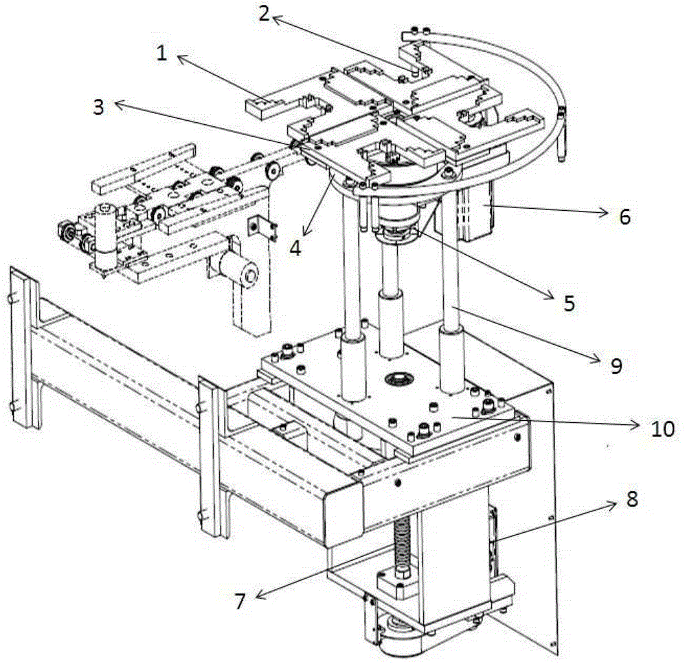
图1是本发明的结构示意图Fig. 1 is a structural representation of the present invention
图中:In the picture:
1、料盒 2、传送口 3、CMOS激光传感器1.
4、托板 5、旋转托架 6、旋转电机4.
7、滚珠丝杠 8、步进电机 9、导杆7.
10、升降台10. Lifting platform
具体实施方式Detailed ways
如图1所示,本发明包括料盒1、托板4、旋转托架5、旋转电机6、导杆9、升降台10、滚珠丝杠7、步进电机8和光纤式光电感应开关3,料盒1有四个,均位于托板4上。As shown in Figure 1, the present invention includes a
料盒1呈矩形,每个矩形料盒1的一边开有一个传送口2,开有传送口2的矩形边的对边为底边,其余两边为邻边,每个料盒1的底边与另一个料盒1的邻边相邻,每两相邻料盒1的传送口2开口方向相差90度。The
料盒1上还设有CMOS激光传感器3,托板4下设有旋转托架5和旋转电机6,旋转托架5与旋转电机6相连;托板4下还设有三根导杆9,导杆9下端均固定在升降台10上,升降台10与滚珠丝杠7通过滚珠螺母连接,滚珠丝杠7与所述步进电机8相连。The
本实例的工作过程:将四个硅片料盒1放到托板4上,其中一个料盒1对准输送皮带线,首先旋转电机6将料盒1精确旋转到上料位置,定位精度误差<0.09度,重复精度误差=0,旋转定位后,步进电机8驱动滚珠丝杠7传动,由升降台10带动导杆9、旋转托架5、托板4使料盒1连续下降,高精度CMOS激光传感器3检测确认硅片是否到位,到位后减速下行,稳当、精确放到输送带上,输送带运转,将硅片送出,直至此料盒1的硅片全部送出;当工作位料盒1取空后,CMOS激光传感器3发出信号,将托板4上升至高位,此时旋转电机6将托板4旋转90°,将另一个料盒1旋转至工作位,继续下降输送硅片;如此反复,直至四个料盒1全部取空后,发出报警信号,提示操作人员更换料盒1。The working process of this example: put four silicon
另外,本发明还设置了料盒安全开关4个,确保料盒由于某种意外原因导致倾斜时停机报警,以有效地保护盒中硅片。In addition, the present invention is also provided with 4 magazine safety switches to ensure that the magazine will stop and give an alarm when the magazine tilts due to some unexpected reason, so as to effectively protect the silicon chips in the magazine.
本发明的电机控制装置:电机控制部分主要是采用了数字运动控制器、可编程控制器、伺服电机驱动器、伺服电机相结合的控制方法,数控器通过程序同时控制托架、导杆、滚珠丝杠等多个轴的行程、速度、延迟等实现多种控制,配合伺服电机驱动器和伺服电机的使用,使得料盒运行的准确性和稳定性得到很好的保障。The motor control device of the present invention: the motor control part mainly adopts a control method combining a digital motion controller, a programmable controller, a servo motor driver, and a servo motor, and the numerical control device simultaneously controls the bracket, the guide rod, and the ball wire The stroke, speed and delay of multiple axes such as bars can be controlled in a variety of ways, and with the use of servo motor drivers and servo motors, the accuracy and stability of the operation of the material box are well guaranteed.
本发明的调试软件程序:增加料盒旋转和旋转定位语句,同时设备的各部分控制具有手动和自动功能,并有状态显示,硅片旋转倒角加工起始和停止位置可任意调整,速度可调,根据需要实现变速,一周(360°)加工在不同区间能实现不同速度。其次,运行出现问题时,指示灯和蜂鸣器报警,提醒操作人员处理,设备停止运行,同时报警内容在工控屏上指示报警内容和故障。The debugging software program of the present invention: increase the material box rotation and rotation positioning sentences, and at the same time, the control of each part of the equipment has manual and automatic functions, and has a status display, and the starting and stopping positions of the silicon chip rotary chamfering processing can be adjusted arbitrarily, and the speed can be adjusted. It can be adjusted to achieve variable speed according to the needs, and different speeds can be realized in different intervals during one round (360°) processing. Secondly, when there is a problem in the operation, the indicator light and the buzzer will alarm to remind the operator to deal with it, and the equipment will stop running. At the same time, the alarm content and the fault will be indicated on the industrial control screen.
以上对本发明的一个实施例进行了详细说明,但所述内容仅为本发明的较佳实施例,不能被认为用于限定本发明的实施范围。凡依本发明申请范围所作的均等变化与改进等,均应仍归属于本发明的专利涵盖范围之内。An embodiment of the present invention has been described in detail above, but the content described is only a preferred embodiment of the present invention, and cannot be considered as limiting the implementation scope of the present invention. All equivalent changes and improvements made according to the application scope of the present invention shall still belong to the scope covered by the patent of the present invention.
Claims (3)
Priority Applications (1)
| Application Number | Priority Date | Filing Date | Title |
|---|---|---|---|
| CN201210495683.3A CN102976123B (en) | 2012-11-28 | 2012-11-28 | A kind of feed mechanism of chamfering device |
Applications Claiming Priority (1)
| Application Number | Priority Date | Filing Date | Title |
|---|---|---|---|
| CN201210495683.3A CN102976123B (en) | 2012-11-28 | 2012-11-28 | A kind of feed mechanism of chamfering device |
Publications (2)
| Publication Number | Publication Date |
|---|---|
| CN102976123A true CN102976123A (en) | 2013-03-20 |
| CN102976123B CN102976123B (en) | 2015-09-02 |
Family
ID=47850553
Family Applications (1)
| Application Number | Title | Priority Date | Filing Date |
|---|---|---|---|
| CN201210495683.3A Active CN102976123B (en) | 2012-11-28 | 2012-11-28 | A kind of feed mechanism of chamfering device |
Country Status (1)
| Country | Link |
|---|---|
| CN (1) | CN102976123B (en) |
Cited By (2)
| Publication number | Priority date | Publication date | Assignee | Title |
|---|---|---|---|---|
| CN111785908A (en) * | 2020-06-23 | 2020-10-16 | 合肥国轩高科动力能源有限公司 | A C-type rotating platform for battery injection, fork and reclaiming |
| CN119349296A (en) * | 2024-12-20 | 2025-01-24 | 苏州鑫捷顺精密科技股份有限公司 | A sheet material feeding device and a feeding method thereof |
Citations (9)
| Publication number | Priority date | Publication date | Assignee | Title |
|---|---|---|---|---|
| JPS57166250A (en) * | 1981-04-03 | 1982-10-13 | Dainippon Screen Mfg Co Ltd | Conveyance positioning device of sheet material |
| US5052540A (en) * | 1988-07-26 | 1991-10-01 | Honda Giken Kogyo Kabushiki Kaisha | Rotary transfer system |
| EP1516699B1 (en) * | 2003-09-19 | 2008-10-08 | Feintool International Holding | Production and/or assembly device |
| CN101316677A (en) * | 2005-11-26 | 2008-12-03 | 阿尔冯·凯斯勒专用机械制造有限公司 | Workholding device and processing machine tool equipped with the same |
| CN201195639Y (en) * | 2008-04-14 | 2009-02-18 | 无锡市易控系统工程有限公司 | Full-automatic transmission apparatus for wafer |
| CN201610323U (en) * | 2010-02-10 | 2010-10-20 | 无锡先导自动化设备有限公司 | Takeout mechanism of silicon chips in box |
| CN201681805U (en) * | 2010-05-14 | 2010-12-22 | 常州捷佳创精密机械有限公司 | An automatic lifting and rotating working device for silicon wafers |
| CN102717298A (en) * | 2012-06-28 | 2012-10-10 | 杜桂林 | Intermittently rotational multi-station feeding device |
| CN203048231U (en) * | 2012-11-28 | 2013-07-10 | 天津市环欧半导体材料技术有限公司 | Feeding mechanism for chamfering equipment |
-
2012
- 2012-11-28 CN CN201210495683.3A patent/CN102976123B/en active Active
Patent Citations (9)
| Publication number | Priority date | Publication date | Assignee | Title |
|---|---|---|---|---|
| JPS57166250A (en) * | 1981-04-03 | 1982-10-13 | Dainippon Screen Mfg Co Ltd | Conveyance positioning device of sheet material |
| US5052540A (en) * | 1988-07-26 | 1991-10-01 | Honda Giken Kogyo Kabushiki Kaisha | Rotary transfer system |
| EP1516699B1 (en) * | 2003-09-19 | 2008-10-08 | Feintool International Holding | Production and/or assembly device |
| CN101316677A (en) * | 2005-11-26 | 2008-12-03 | 阿尔冯·凯斯勒专用机械制造有限公司 | Workholding device and processing machine tool equipped with the same |
| CN201195639Y (en) * | 2008-04-14 | 2009-02-18 | 无锡市易控系统工程有限公司 | Full-automatic transmission apparatus for wafer |
| CN201610323U (en) * | 2010-02-10 | 2010-10-20 | 无锡先导自动化设备有限公司 | Takeout mechanism of silicon chips in box |
| CN201681805U (en) * | 2010-05-14 | 2010-12-22 | 常州捷佳创精密机械有限公司 | An automatic lifting and rotating working device for silicon wafers |
| CN102717298A (en) * | 2012-06-28 | 2012-10-10 | 杜桂林 | Intermittently rotational multi-station feeding device |
| CN203048231U (en) * | 2012-11-28 | 2013-07-10 | 天津市环欧半导体材料技术有限公司 | Feeding mechanism for chamfering equipment |
Cited By (3)
| Publication number | Priority date | Publication date | Assignee | Title |
|---|---|---|---|---|
| CN111785908A (en) * | 2020-06-23 | 2020-10-16 | 合肥国轩高科动力能源有限公司 | A C-type rotating platform for battery injection, fork and reclaiming |
| CN111785908B (en) * | 2020-06-23 | 2022-02-18 | 合肥国轩高科动力能源有限公司 | A C-type rotating platform for battery injection, fork and reclaiming |
| CN119349296A (en) * | 2024-12-20 | 2025-01-24 | 苏州鑫捷顺精密科技股份有限公司 | A sheet material feeding device and a feeding method thereof |
Also Published As
| Publication number | Publication date |
|---|---|
| CN102976123B (en) | 2015-09-02 |
Similar Documents
| Publication | Publication Date | Title |
|---|---|---|
| CN202758535U (en) | Industrial robot and machine vision system | |
| CN203581497U (en) | Positioning and clamping mechanism of automatic case unpacker | |
| CN202622185U (en) | Cutting machine | |
| CN105598674B (en) | Full-automatic automobile instrument panel pointer cap head compact system | |
| CN105292639A (en) | Hose labeling machine | |
| CN104175213A (en) | Intelligent mechanical arm | |
| CN104444474A (en) | Automatic separating, testing, sorting and packaging machine for long-strip-shaped LED optical assemblies | |
| CN102553840B (en) | A kind of storage type tridimensional automatic sorting device towards slewing parts | |
| CN203048231U (en) | Feeding mechanism for chamfering equipment | |
| CN104229461B (en) | A kind of material-pulling device | |
| CN206215734U (en) | Fan blade kludge | |
| CN102976123B (en) | A kind of feed mechanism of chamfering device | |
| CN205520352U (en) | Full automatization motormeter index cap head suppression system | |
| CN206985329U (en) | A kind of wire rod material arranging apparatus | |
| CN110386388B (en) | Automatic system for withdrawing three-dimensional warehouse and robot goods taking | |
| CN110371362A (en) | A kind of dixie cup packaging industry mechanical arm with automatic heap azido functional | |
| CN104907225A (en) | Automatic turntable glue injection system and glue injection detection method thereof | |
| CN210913051U (en) | Paper cup packaging industry mechanical arm with automatic stacking function | |
| CN203461514U (en) | Material pushing device | |
| CN105236109B (en) | One kind forging and stamping pipeline hopper blanking detection device | |
| CN205150339U (en) | Automatic dress of heap holds in palm machine | |
| CN105710250B (en) | A kind of press machine automatic feeding system with fault tolerance | |
| CN213516900U (en) | A network transformer module detection and coding system based on machine vision | |
| CN204545215U (en) | A kind of automatic material taking mechanism of pressing robot | |
| CN203993517U (en) | Puma manipulator |
Legal Events
| Date | Code | Title | Description |
|---|---|---|---|
| C06 | Publication | ||
| PB01 | Publication | ||
| C10 | Entry into substantive examination | ||
| SE01 | Entry into force of request for substantive examination | ||
| C14 | Grant of patent or utility model | ||
| GR01 | Patent grant | ||
| TR01 | Transfer of patent right | ||
| TR01 | Transfer of patent right |
Effective date of registration: 20181105 Address after: 300384 Tianjin Binhai New Area high tech Zone Huayuan Industrial Area (outside the ring) Hai Tai Road 12 Patentee after: TIANJIN ZHONGHUAN ADVANCED MATERIAL TECHNOLOGY Co.,Ltd. Address before: 300384 Tianjin Binhai New Area high tech Zone Huayuan Industrial Park (outside the ring) Hai Tai Road 12 Patentee before: TIANJIN HUANOU SEMICONDUCTOR MATERIAL TECHNOLOGY Co.,Ltd. |
|
| TR01 | Transfer of patent right | ||
| TR01 | Transfer of patent right |
Effective date of registration: 20191210 Address after: 214200 Dongfen Avenue, Yixing Economic and Technological Development Zone, Wuxi City, Jiangsu Province Co-patentee after: TIANJIN ZHONGHUAN ADVANCED MATERIAL TECHNOLOGY Co.,Ltd. Patentee after: Zhonghuan leading semiconductor materials Co.,Ltd. Address before: 300384 in Tianjin Binhai high tech Zone Huayuan Industrial Zone (outer ring) Haitai Road No. 12 Patentee before: TIANJIN ZHONGHUAN ADVANCED MATERIAL TECHNOLOGY Co.,Ltd. |
|
| CP03 | Change of name, title or address | ||
| CP03 | Change of name, title or address |
Address after: 214200 Dongjia Avenue, Yixing Economic and Technological Development Zone, Wuxi City, Jiangsu Province Patentee after: Zhonghuan Leading Semiconductor Technology Co.,Ltd. Country or region after: China Patentee after: TIANJIN ZHONGHUAN ADVANCED MATERIAL TECHNOLOGY Co.,Ltd. Address before: 214200 Dongjia Avenue, Yixing Economic and Technological Development Zone, Wuxi City, Jiangsu Province Patentee before: Zhonghuan leading semiconductor materials Co.,Ltd. Country or region before: China Patentee before: TIANJIN ZHONGHUAN ADVANCED MATERIAL TECHNOLOGY Co.,Ltd. |