CN102828825A - Symmetrical biphase cam swing type internal combustion engine with high rotating speed - Google Patents
Symmetrical biphase cam swing type internal combustion engine with high rotating speed Download PDFInfo
- Publication number
- CN102828825A CN102828825A CN2012103555366A CN201210355536A CN102828825A CN 102828825 A CN102828825 A CN 102828825A CN 2012103555366 A CN2012103555366 A CN 2012103555366A CN 201210355536 A CN201210355536 A CN 201210355536A CN 102828825 A CN102828825 A CN 102828825A
- Authority
- CN
- China
- Prior art keywords
- ring gear
- double phase
- swing type
- combustion engine
- oscillating tooth
- Prior art date
- Legal status (The legal status is an assumption and is not a legal conclusion. Google has not performed a legal analysis and makes no representation as to the accuracy of the status listed.)
- Pending
Links
Images

Abstract
The invention discloses a symmetrical biphase cam swing type internal combustion engine with high rotating speed, relating to the field of combustion gas power. The invention provides a novel internal combustion engine, wherein eight cylinders are annularly, symmetrically and uniformly distributed at the periphery of an externally-protruding inner gear ring so that a resultant force borne by the externally-protruding inner gear ring is equal to zero; pistons of the cylinders are directly acted on the externally-protruding inner gear ring through push rods; and power is transferred to an output shaft in key joint with a symmetrical biphase cam by the externally-protruding inner gear ring through the transmission of a symmetrical biphase cam swing type oscillating tooth. A connecting rod and a crankshaft in the traditional internal combustion engine are omitted in the symmetrical biphase cam swing type internal combustion engine with high rotating speed, and an externally-protruding inner biphase shock wave swing type transmission mechanism of the internal combustion engine has no eccentric mass and has the advantage of self-balancing an inertia force and a working load. The rotating speed of the output shaft depends on the transmission ratio of the oscillating tooth, and if an oscillating tooth rack is fixed, the symmetrical biphase cam gives output at a high speed, so that the symmetrical biphase cam swing type internal combustion engine with high rotating speed can be widely applied to the fields such as a helicopter engine, a small generator and the like requiring high-speed rotation and can be used for reducing the emission of harmful gases when the output rotating speed is constant. The internal combustion engine is simple and compact in structure, is self-balancing in stress and stable in operation.
Description
Technical field
The present invention relates to the gas power field, more particularly, is the high rotating speed internal-combustion engine of a kind of symmetrical double phase cam swing type.
Background technique
At present, general internal-combustion engine (motor) all is made up of body, connecting rod, distribution device, cooling system, lubrication system, oil-fired system and ignition system etc., and that working procedure is divided is air-breathing, compression, work by combustion, four strokes of exhaust.What the driving mechanism of this type internal-combustion engine used all is connecting rod, gives bent axle through connecting rod with the transmission of power of piston, and changes the linear reciprocating motion of piston into bent axle rotatablely move.Because this type internal-combustion engine is to lean on the plane motion of straight line motion and the connecting rod of piston to oppress to order about bent axle to rotate, and exists bigger friction between each kinematic pair thereby cause, and causes the internal-combustion engine transmission efficiency low.These existing crankshaft-link rod type internal-combustion engines also have following major defect: volume is big; Uneven centrifugal force on connecting rod, the bent axle is bigger; Impact greatly, vibration is big; And cause bigger mechanical wear thus, internal-combustion engine life-span is shortened; Difficulty is all compared in complex structure, processing, manufacturing, assembling etc.; In addition, general internal-combustion engine and speed change gear are two independently machines, and internal-combustion engine needs the other speed changer of installing to be used for follow-up speed change usually, causes bulky.
?
Summary of the invention
The objective of the invention is: for overcoming the above-mentioned shortcoming that existing crankshaft-link rod type internal-combustion engine exists, the present invention provides a kind of high speed quartastroke engine---high rotating speed internal-combustion engines of symmetrical double phase cam swing type simple and compact for structure, characteristics such as volume is little, impact shock is little, running is steady, power is big, the life-span is long, efficient height that have.
The technological scheme that the present invention is taked for its technical problem of solution is: the high rotating speed internal-combustion engine of a kind of symmetrical double phase cam swing type; Mainly form by cylinder head (1), exhaust valve (2), intake valve (3), cylinder (4), cylinder body (5), push rod (6), piston (7), spring (8), roller (9), evagination ring gear (10), oscillating tooth (11), movable teeth rack (12), symmetrical double phase cam (13), oscillating tooth pin (14), output shaft (15) and oil supply system, starting system, lubrication system, cooling system, gas distribution system; It is characterized in that: eight cylinders (4) circular symmetric be evenly arranged in evagination ring gear (10) around; Two phase shock wave swinging transmission mechanisms change the linear reciprocating motion of piston into output shaft rotatablely move in the evagination---and cylinder piston (7) directly acts on the evagination ring gear (10) through push rod (6); Promote evagination ring gear (10) rotation; The inside toothed surface of evagination ring gear (10) promotes oscillating tooth (11) around oscillating tooth pin (14) swing that is fixed on the movable teeth rack (12); And movable teeth rack (12) is fixedly connected with frame; So oscillating tooth (11) is meshed with symmetrical double phase cam (13) under the common effect of contraction of movable teeth rack and oscillating tooth pin; Order about symmetrical double phase cam (13) and rotate, thereby power is passed to output shaft (15) output with symmetrical double phase cam (13) key connecting.
In technique scheme; Two phase shock wave swinging transmission mechanisms are organically combined by cam mechanism and symmetrical double phase cam swing type movable tooth drive mechanism in the evagination; Cam mechanism wherein is made up of piston (7), spring (8), push rod (6), roller (9), evagination ring gear (10), cylinder body (5); One end of push rod (6) and piston (7) are fixedly connected, and the other end is installed roller (9), and roller (9) makes between push rod (6) and the evagination ring gear (10) and connects for rolling friction; One end of spring (8) is fixed on the bottom of piston (7); The other end is fixed on the boss of cylinder (4) bottom, and spring (8) contacts the roller (9) on the push rod (6) all the time with evagination ring gear (10), and each cylinder all is furnished with the push rod and the spring of piston, band roller.
Symmetry double phase cam swing type movable tooth drive mechanism is made up of evagination ring gear (10), movable teeth rack (12), symmetrical double phase cam (13), output shaft (15), oscillating tooth (11) and oscillating tooth pin (14); The outer surface of evagination ring gear (10) is four phase cam profiles; Inside is the ring gear toothed surface in the symmetrical double phase cam swing type Oscillating Tooth Gear Reducer; So evagination ring gear (10) is the cam in the cam mechanism; It is again the ring gear in the symmetrical double phase cam swing type movable tooth drive mechanism; Evagination ring gear (10) organically unites two into one internal-combustion engine and symmetrical double phase cam swing type movable tooth drive mechanism, and whole symmetrical double phase cam swing type movable tooth drive mechanism is built in the inside of evagination ring gear (10).Symmetry double phase cam (13) self shape is 180 degree centers symmetry, the sole mass complete equilibrium, and its profilogram is the standard ellipse curve, or is the two-phase cosine curve, or is two eccentric arc curves.
The outer surface cam profile curve of evagination ring gear (10) can be selected according to the actual design needs, to obtain best dynamic performance, improves the energy conversion efficiency of internal-combustion engine.The shaft axis of output shaft (15), evagination ring gear (10), movable teeth rack (12) and symmetrical double phase cam parts such as (13) overlaps and is supported by rack bearing.Oscillating tooth is counted Z
11Wave number Z with evagination ring gear (10)
10Differ is 2; Movable teeth rack (12) connects firmly with frame; Symmetry double phase cam (13) and output shaft (15) key connecting; Oscillating tooth pin (14) circumferentially is uniformly distributed with and is fixed on the movable teeth rack (12), and oscillating tooth (11) is formed revolute pair with oscillating tooth pin (14), and oscillating tooth (11) also is meshed respectively with evagination ring gear (10), symmetrical double phase cam (13) simultaneously and respectively forms a higher pair.
In technique scheme; The outside of evagination ring gear (10) is four phase cams with four projections that are mutually 90 ° of angles and axle center symmetry; Eight cylinders (4) circular symmetric be distributed on evagination ring gear (10) around; Cylinder piston (7) working state of wherein any two 180 ° of symmetric arrangement of being separated by is synchronous, and 180 ° two cylinder pistons of will being separated by are as one group, and then cylinder can be divided into four groups; Four groups of cylinder pistons carry out suction stroke, compression stroke, gaseous combustion expansion stroke and exhaust stroke successively, and the stroke of piston process of two adjacent groups cylinder is 45 ° corresponding to the phase difference of evagination ring gear (10) corner.The output shaft rotating speed depends on the velocity ratio of symmetrical double phase cam swing type Oscillating Tooth Gear Reducer, and suitably select symmetrical double phase cam swing type Oscillating Tooth Gear Reducer join the tooth scheme, can obtain less velocity ratio, can realize output at a high speed.
Compared with present technology main inventive point of the present invention is.
1. eight air cylinder annular symmetries are distributed on around the evagination ring gear, and cylinder piston directly acts on the evagination ring gear through push rod, and power is passed to output shaft output by the evagination ring gear through symmetrical double phase cam swing type Oscillating Tooth Gear Reducer.
2. the outside of evagination ring gear is to have four four phase cams that are mutually 90 ° of angle projections; And inside is the structure of ring gear toothed surface, and symmetrical double phase cam swing type movable tooth drive mechanism is built in the cam of cam mechanism, and cam and the ring gear in the symmetrical double phase cam swing type movable tooth drive mechanism in the cam mechanism are united two into one; Obtain two phase shock wave swinging transmission mechanisms in the evagination; And, the Oscillating Tooth Gear Reducer technology is introduced technical field of internal combustion engines with the connecting rod in the existing crankshaft-link rod type internal-combustion engine of this new mechanism replacement, not only thoroughly removed crankshaft-and-connecting-rod; And internal-combustion engine and speed change gear (speed increaser) united two into one; Obtained a kind of compact structure, small and exquisite novel high rotary speed power machine, compared with crankshaft-link rod type internal-combustion engine, internal-combustion engine axial dimension of the present invention reduces greatly; And under same rotational speed required, discharge of harmful gases reduced greatly.
3. the pto of internal-combustion engine is the output shaft that connects with symmetrical two-phase cam key; Symmetry double phase cam swing type Oscillating Tooth Gear Reducer is by evagination ring gear input power, and movable teeth rack is fixed, symmetrical double phase cam output; Can realize less velocity ratio, internal-combustion engine high speed outputting power.
4. the output shaft rotating speed depends on the rotating speed of evagination ring gear and the velocity ratio of symmetrical double phase cam swing type Oscillating Tooth Gear Reducer; And suitably select symmetrical double phase cam swing type Oscillating Tooth Gear Reducer join the tooth scheme; Can obtain less velocity ratio, and shock wave device is symmetrical double phase cam, oscillating tooth is counted Z
11Wave number Z with the evagination ring gear
10Differing is 2, does not need eccentric the installation, and entire internal combustion engine receives force self-balanced.
5. in the symmetrical double phase cam swing type Oscillating Tooth Gear Reducer, evagination ring gear and oscillating tooth are multiple tooth engagement, thus can realize more high-power, internal combustion engine operation is steady.
The present invention has following beneficial technical effects.
1. impact shock is little, noise is little, running is steady
Two phase shock wave swinging transmission mechanisms have replaced the connecting rod in the existing crankshaft-link rod type internal-combustion engine in the evagination because the present invention adopts; Completely abolished crankshaft-and-connecting-rod; Evagination ring gear and symmetrical double phase cam swing type Oscillating Tooth Gear Reducer all are axially symmetric structures; There are not eccentric mass and uneven centrifugal force; Eliminated because of bent axle mass eccentricity, connecting rod do inertial force and tilting moment and consequent impact shock and noise that plane motion causes, eliminated the connecting rod beat and caused piston to bounce vibration and noise that cylinder wall causes; Eight air cylinder annular symmetries are distributed on around the evagination ring gear, and the cylinder piston working state of wherein any two 180 ° of symmetric arrangement of being separated by is synchronous, that is: or simultaneously air-breathing or compression simultaneously or acting of gaseous combustion simultaneously or exhaust simultaneously; Therefore; The appearance that impact force is always paired can be cancelled out each other, and it is zero that the evagination ring gear is made a concerted effort; So impact shock is less, thereby internal combustion engine operation is very steady.
Compact structure, volume is little, in light weight, axial dimension is little
Owing to cancelled the bent axle of bulky complex; Each air cylinder annular symmetry is distributed on around the evagination ring gear; And symmetrical double phase cam swing type movable tooth drive mechanism is built in the evagination ring gear; The evagination ring gear is the cam in the cam mechanism, is again the ring gear in the symmetrical double phase cam swing type movable tooth drive mechanism, so Structure of Internal-Combustion Engine of the present invention is compact, axial dimension is little, volume is little, in light weight; The present invention adopts the power that two phase shock wave swinging transmission mechanism output pistons produce in the evagination, and internal-combustion engine and speed change gear are united two into one, and need not other distribution transforming quick-mounting and puts, and structure is reduced greatly, so compact structure, small and exquisite.
3. velocity ratio is less, the integrated speedup of complete machine, high rotating speed output
The pto of this internal-combustion engine is the output shaft that connects with symmetrical two-phase cam key; Symmetry double phase cam swing type Oscillating Tooth Gear Reducer is with evagination ring gear input power; Movable teeth rack is fixed, and symmetrical double phase cam output suitably selects to join the tooth scheme; Can realize less velocity ratio, and still keep plurality of advantages such as compact structure, quality is little, volume is little.Internal-combustion engine high speed outputting power can be widely used in needing high-revolving field, such as small generator, helicopter engine etc.High rotational speed output when the demand rotating speed is certain, can significantly reduce discharge of harmful gases, reaches the purpose of energy-saving and emission-reduction.
Fretting wear little, receive force self-balanced, oil consumption is low, efficient is high, the life-span is long
Symmetrical double phase cam swing type Oscillating Tooth Gear Reducer is passed to output shaft output because the driving force of piston is directly passed to the evagination ring gear through the push rod roller.For rolling friction connects, transmission efficiency is high between piston push rod and the evagination ring gear, has cancelled serious wear, connecting rod that friction power loss is big.Symmetry double phase cam swing type Oscillating Tooth Gear Reducer is that multiple tooth engagement, bearing capacity are bigger, and transmission efficiency is high, and because of multiple tooth engagement simultaneously, output rigidity is big, and transmission is also more steadily reliable.Symmetrical double phase cam can be realized shock wave and guarantee himself and the stressed autobalance of all oscillating tooths simultaneously; In transmission device, do not exist a tooth difference Oscillating Tooth Gear Reducer inertial force, excitation force and the tilting moment etc. that shock wave device exists to be installed because of off-centre; Avoided the vibrational excitation of transmission device from transmission principle; Thereby help improving the efficient of transmission, its efficiency value can reach more than 0.9.The mechanical friction wearing and tearing are also less, and oil consumption is low, and internal-combustion engine life-span is longer.
5. have good and economic, power character and exhaust index
Because the characteristics of motion of piston depends on the exterior contour curve of evagination ring gear fully; So can design cam profile through choosing appropriate piston motion rule; And appropriate piston motion rule should make abundant, perfect, the fuel thermal energy utilization ratio height of gaseous combustion in the cylinder; Therefore, internal-combustion engine of the present invention has good power character, Economy and exhaust index, can reach energy-conserving and environment-protective and the purpose that improves gear efficiency.
6. simple in structure, good manufacturability, cost of production are low
Design of part in the internal-combustion engine of the present invention is simple, good manufacturability, cost of production are low, has completely abolished the crankshaft-and-connecting-rod of complex structure, manufacturing difficulty.
7. bearing capacity is bigger, and rotating speed is steady
Symmetry double phase cam swing type Oscillating Tooth Gear Reducer is multiple tooth engagement, stable drive, and oscillating tooth can be shared load jointly and realize power dividing.So internal combustion engine operation is steady, the ability of opposing shock and vibration is stronger, and bearing capacity is big.
Description of drawings
Below in conjunction with accompanying drawing and embodiment the present invention is described further.But what particularly point out is; Embodiment of the present invention is not limited to the described form of following embodiment; The those skilled in the art is under the situation of not paying creative work; Also can design other embodiment at an easy rate, therefore should the embodiment of embodiment given below be interpreted as protection scope of the present invention, protection scope of the present invention is limited in given embodiment.
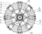
Fig. 1 is the structural representation of the high rotating speed internal-combustion engine of symmetrical double phase cam swing type.
Fig. 2 is the schematic representation of evagination ring gear and symmetrical double phase cam swing type oscillating tooth mechanism.
Above-mentioned respectively attach sign that picture in picture knows label to as if: 1 cylinder head, 2 exhaust valves, 3 intake valves, 4 cylinders, 5 cylinder bodies, 6 push rods, 7 pistons, 8 springs, 9 rollers, 10 evagination ring gears, 11 oscillating tooths, 12 movable teeth racks, 13 symmetrical double phase cams, 14 oscillating tooth pins, 15 output shafts.
Specific embodiment
Fig. 1; The high rotating speed internal-combustion engine of symmetrical double phase cam swing type shown in Figure 2 is made up of cylinder head (1), exhaust valve (2), intake valve (3), cylinder (4), cylinder body (5), push rod (6), piston (7), spring (8), roller (9), evagination ring gear (10), oscillating tooth (11), movable teeth rack (12), symmetrical double phase cam (13), oscillating tooth pin (14), output shaft (15) etc.Eight cylinders (4) axle center symmetrically annular be distributed on evagination ring gear (10) around, the angle of adjacent two cylinders is 45 °.A piston (7) is arranged in each cylinder (4); One end of push rod (6) and piston (7) are consolidated; The other end is equipped with roller (9), and it is that rolling friction connects that roller (9) makes connecting between push rod (6) and the evagination ring gear (10), and an end of spring (8) is fixed on piston (7) bottom; The other end is fixed on the boss of cylinder (4) bottom, and the effect of spring (8) is that the roller (9) on the push rod (6) is contacted with evagination ring gear (10) all the time.The outside of evagination ring gear (10) is four phase cams with four projections that are mutually 90 ° of angles and axle center symmetry, and inside is the ring gear toothed surface.Evagination ring gear (10) is organically integrated cam mechanism and symmetrical double phase cam swing type movable tooth drive mechanism.Evagination ring gear (10) is the cam in the cam mechanism, is again the ring gear in the symmetrical double phase cam swing type movable tooth drive mechanism, and whole symmetrical double phase cam swing type movable tooth drive mechanism is embedded in the inside of evagination ring gear (10).The profilogram of symmetry double phase cam (13) can be standard ellipse curve or two-phase cosine curve or two eccentric gardens arc curve; So symmetrical double phase cam (13) self shape is 180 ° of center symmetries; The sole mass complete equilibrium, the selection standard elliptic curve is the profilogram of symmetrical double phase cam (13) in the present embodiment.Symmetry double phase cam swing type movable tooth drive mechanism is formed by evagination ring gear (10), oscillating tooth (11), movable teeth rack (12), symmetrical double phase cam (13), oscillating tooth pin (14) with the output shaft (15) of symmetrical double phase cam (13) key connecting.Movable teeth rack (12) connects firmly with frame; Oscillating tooth pin (14) circumferentially is uniformly distributed with and is fixed on the movable teeth rack (12); Oscillating tooth (11) can be done oscillating motion around oscillating tooth pin (14); Oscillating tooth and oscillating tooth pin (14) form revolute pair, oscillating tooth (11) simultaneously also with evagination ring gear (10), symmetrical double phase cam (13) the formation higher pair that is meshed respectively.The shaft axis of output shaft (15), evagination ring gear (10), movable teeth rack (12) and symmetrical double phase cam parts such as (13) overlaps and is supported by rack bearing.Therefore internal-combustion engine of the present invention not only has the series of advantages of symmetrical double phase cam swing type Oscillating Tooth Gear Reducer, and structure is very compact.The outer surface cam profile curve of evagination ring gear (10) can be chosen different curves on demand.Present embodiment is made the cosine acceleration motion rule by piston (7) and is confirmed cam profile curve; Promptly when evagination ring gear (10) uniform rotation; Piston (7) does reciprocating linear motion by the cosine acceleration motion rule, and its cycle of motion is 1/4th of evagination ring gear (a 10) period of rotation.The pto of present embodiment internal-combustion engine is the output shaft (15) that connects with symmetrical two-phase cam key; Symmetry double phase cam swing type Oscillating Tooth Gear Reducer is with evagination ring gear input power; Movable teeth rack is fixed; The output of symmetry double phase cam can realize bigger velocity ratio, but internal-combustion engine high speed outputting power.
The working principle of internal-combustion engine according to the invention is: when internal combustion engine; Piston (7) in the gaseous combustion acting cylinder; Its driving force acts on the evagination ring gear (10) through push rod (6) and roller (9); Promote evagination ring gear (10) and be rotated counterclockwise, power is passed to output shaft (15) output by evagination ring gear (10) through symmetrical double phase cam swing type movable tooth drive mechanism; Because the rotation of evagination ring gear (10), roller (9) rolls and make push rod (6) and the piston (7) that not have to do work slides in cylinder (4) along evagination ring gear (10) profile, accomplishes the task of air-breathing or pressurized gas or exhaust.In Fig. 1, with cylinder a and e, b and f, c and g, d and h each as one group, then can be divided into four groups of cylinders.If the piston among cylinder a, the e is in the initial position of suction stroke; Piston among cylinder b, the f is in the initial position of compression stroke; Piston among cylinder c, the g is in the initial position of gaseous combustion expansion stroke; Piston among cylinder d, the h is in the initial position of exhaust stroke, and the stroke process of two adjacent groups cylinder piston differs a stroke, is 45 ° corresponding to the phase difference of evagination ring gear (10) corner.Then evagination ring gear (10) turns over after 45 ° counterclockwise; Cylinder b, the f acting that takes fire again, the evagination ring gear turns over after 45 ° more counterclockwise, cylinder a, the e acting that takes fire again; Then cylinder d, the h acting that takes fire after cylinder a, e work by combustion accomplish; Take turns to cylinder c and g work by combustion afterwards again, so circulation is gone down, and makes evagination ring gear (10) running reposefully continuously; The internal tooth form face of evagination ring gear promotes oscillating tooth (11) and swings around oscillating tooth pin (14); Under the common effect of contraction of movable teeth rack (12) and oscillating tooth pin (14), force the engagement of oscillating tooth (11) and symmetrical double phase cam (13), drive symmetrical double phase cam (13) and rotate, and by reposefully power and motion being exported continuously with the output shaft (15) of symmetrical double phase cam (13) key connecting.180 ° of symmetric arrangement because two cylinders in every group of cylinder are separated by; And working state is identical at any time; So eight pistons (7) to the comprehensive function effect of evagination ring gear (10) are: evagination ring gear (10) only receives the effect of pure couple, and to make a concerted effort be zero.Because evagination ring gear (10) and symmetrical double phase cam swing type movable tooth drive mechanism not only have structural symmetry, and stressed also be symmetrical, so be zero their suffered making a concerted effort, only receive force couple role.Therefore the impact shock of internal-combustion engine of the present invention is little, and running steadily.
Be the speed change characteristic of explanation internal-combustion engine of the present invention, the number of teeth of establishing oscillating tooth (11) is for
; The wave number of evagination ring gear (10) is
; The rotating speed of evagination ring gear (10) is
 r/min; Movable teeth rack (12) is fixedly connected (angular velocity of movable teeth rack
 ) with frame, the velocity ratio of then symmetrical double phase cam swing type Oscillating Tooth Gear Reducer is:

So: n
15=n
13=2400r/min; It is thus clear that symmetrical double phase cam (13), output shaft (15) turn to identical with evagination ring gear (10); The rotating speed of output shaft (15) has significant improvement with respect to the rotating speed of evagination ring gear (10), and internal-combustion engine does not need extra interpolation speed changer just can realize the high speed outputting power.This specific character can be widely used in needing high-revolving field, and such as helicopter engine, small generator etc., output speed one regularly can reduce discharge of harmful gases, reaches the purpose of energy-saving and emission-reduction.
The internal-combustion engine of present embodiment also is provided with starting system, gas distribution system, lubrication system, oil supply system and cooling system etc.
Claims (6)
1. the high rotating speed internal-combustion engine of symmetrical double phase cam swing type; Mainly form by cylinder head (1), exhaust valve (2), intake valve (3), cylinder (4), cylinder body (5), push rod (6), piston (7), spring (8), roller (9), evagination ring gear (10), oscillating tooth (11), movable teeth rack (12), symmetrical double phase cam (13), oscillating tooth pin (14), output shaft (15) and oil supply system, starting system, lubrication system, cooling system, gas distribution system; It is characterized in that: eight cylinders (4) circular symmetric be evenly arranged in evagination ring gear (10) around; Two phase shock wave swinging transmission mechanisms change the linear reciprocating motion of piston into output shaft rotatablely move in the evagination---and cylinder piston (7) directly acts on the evagination ring gear (10) through push rod (6); Promote evagination ring gear (10) rotation; Power passes to output shaft (15) output that connects with symmetrical two-phase cam key by evagination ring gear (10) through symmetrical double phase cam swing type Oscillating Tooth Gear Reducer; Evagination ring gear (10) organically combines internal-combustion engine and symmetrical double phase cam swing type Oscillating Tooth Gear Reducer together; Make internal-combustion engine need not to be equipped with again speed changer, at a high speed output.
2. the high rotating speed internal-combustion engine of symmetrical double phase cam swing type according to claim 1; It is characterized in that: two phase shock wave swinging transmission mechanisms are organically combined by cam mechanism and symmetrical double phase cam swing type movable tooth drive mechanism in the above-mentioned evagination; Cam mechanism wherein is made up of piston (7), spring (8), push rod (6), roller (9), evagination ring gear (10), cylinder body (5); One end of push rod (6) and piston (7) are fixedly connected; The other end is installed roller (9), and roller (9) makes between push rod (6) and the evagination ring gear (10) to rolling friction connects, and an end of spring (8) is fixed on the bottom of piston (7); The other end is fixed on the boss of cylinder (4) bottom, and spring (8) contacts the roller (9) on the push rod (6) all the time with evagination ring gear (10); Symmetry double phase cam swing type movable tooth drive mechanism is made up of evagination ring gear (10), movable teeth rack (12), symmetrical double phase cam (13), output shaft (15), oscillating tooth (11) and oscillating tooth pin (14); And the shaft axis of evagination ring gear (10), movable teeth rack (12) and symmetrical double phase cam (13), output shaft (15) overlaps and is supported by rack bearing; Movable teeth rack (12) is fixed with frame, and oscillating tooth is counted Z
11Wave number Z with evagination ring gear (10)
10Differ is 2; Symmetry double phase cam (13) and output shaft (15) key connecting; Oscillating tooth pin (14) circumferentially is uniformly distributed with and is fixed on the movable teeth rack (12); Oscillating tooth (11) and oscillating tooth pin (14) are formed revolute pair, and oscillating tooth (11) respectively forms a higher pair in oscillating tooth pin (14) swing, being meshed respectively with evagination ring gear (10), symmetrical double phase cam (13).
3. according to claim 1, the high rotating speed internal-combustion engine of 2 described symmetrical double phase cam swing types; It is characterized in that: the outside of above-mentioned evagination ring gear (10) is four phase cams with four projections that are mutually 90 ° of angles and axle center symmetry; Inside is the ring gear toothed surface in the symmetrical double phase cam swing type Oscillating Tooth Gear Reducer; So evagination ring gear (10) is the cam in the cam mechanism; Be again the ring gear in the symmetrical double phase cam swing type movable tooth drive mechanism, whole symmetrical double phase cam swing type movable tooth drive mechanism is embedded in the inside of evagination ring gear (10); Symmetry double phase cam (13) self shape is 180 ° of center symmetries, the sole mass complete equilibrium, and its profilogram is the standard ellipse curve, or is the two-phase cosine curve, or is two eccentric arc curves.
4. according to the high rotating speed internal-combustion engine of the described symmetrical double phase cam swing type of claim 1 to 3; It is characterized in that: the output shaft rotating speed depends on the velocity ratio of symmetrical double phase cam swing type Oscillating Tooth Gear Reducer; And suitably select symmetrical double phase cam swing type Oscillating Tooth Gear Reducer join the tooth scheme; Less velocity ratio can be obtained, output at a high speed can be realized.
5. according to the high rotating speed internal-combustion engine of the described symmetrical double phase cam swing type of claim 1 to 4; It is characterized in that: in the above-mentioned internal-combustion engine eight cylinders (4) circular symmetric be distributed on evagination ring gear (10) around; Cylinder piston (7) working state of wherein any two 180 ° of symmetric arrangement of being separated by is synchronous; To be separated by two cylinder pistons of 180 ° as one group; Then cylinder can be divided into four groups, and four groups of cylinder pistons carry out suction stroke, compression stroke, gaseous combustion expansion stroke and exhaust stroke successively, and the stroke of piston process of two adjacent groups cylinder is 45 ° corresponding to the phase difference of evagination ring gear (10) corner;
Cylinder piston (7) directly acts on the evagination ring gear (10) through push rod (6); Promote evagination ring gear (10) rotation; The toothed surface of evagination ring gear (10) promotes oscillating tooth (11) around oscillating tooth pin (14) swing that is fixed on the movable teeth rack (12); And movable teeth rack (12) is fixedly connected with frame, so oscillating tooth (11) is meshed with symmetrical double phase cam (13) under the effect of contraction of movable teeth rack and oscillating tooth pin, orders about symmetrical double phase cam (13) and rotates; Thereby power is passed to and the output of the output shaft (15) of symmetrical double phase cam (13) key connecting, realized output at a high speed.
6. according to the high rotating speed internal-combustion engine of the described symmetrical double phase cam swing type of claim 1 to 5, it is characterized in that: in the symmetrical double phase cam swing type Oscillating Tooth Gear Reducer, evagination ring gear and oscillating tooth are multiple tooth engagement, thus can realize more high-power, steadily transmission.
Priority Applications (1)
| Application Number | Priority Date | Filing Date | Title |
|---|---|---|---|
| CN2012103555366A CN102828825A (en) | 2012-09-24 | 2012-09-24 | Symmetrical biphase cam swing type internal combustion engine with high rotating speed |
Applications Claiming Priority (1)
| Application Number | Priority Date | Filing Date | Title |
|---|---|---|---|
| CN2012103555366A CN102828825A (en) | 2012-09-24 | 2012-09-24 | Symmetrical biphase cam swing type internal combustion engine with high rotating speed |
Publications (1)
| Publication Number | Publication Date |
|---|---|
| CN102828825A true CN102828825A (en) | 2012-12-19 |
Family
ID=47332102
Family Applications (1)
| Application Number | Title | Priority Date | Filing Date |
|---|---|---|---|
| CN2012103555366A Pending CN102828825A (en) | 2012-09-24 | 2012-09-24 | Symmetrical biphase cam swing type internal combustion engine with high rotating speed |
Country Status (1)
| Country | Link |
|---|---|
| CN (1) | CN102828825A (en) |
Cited By (4)
| Publication number | Priority date | Publication date | Assignee | Title |
|---|---|---|---|---|
| CN103047003A (en) * | 2013-01-15 | 2013-04-17 | 四川大学 | Outside-protruding-inside random tooth difference cam moving type transmission combustion engine |
| CN103061879A (en) * | 2013-01-29 | 2013-04-24 | 四川大学 | Optional tooth difference swing type high-rotation-speed internal-combustion engine |
| CN103147856A (en) * | 2013-01-07 | 2013-06-12 | 四川大学 | Outer convex cam roller transmission internal combustion engine with any inner tooth difference |
| CN104653291A (en) * | 2014-04-09 | 2015-05-27 | 张天送 | Crankshaft-free tangent line transmission multi-staggering elasticity-blocking controllable high speed energy saving engine |
Citations (2)
| Publication number | Priority date | Publication date | Assignee | Title |
|---|---|---|---|---|
| CN101979853A (en) * | 2010-11-10 | 2011-02-23 | 四川大学 | Internal dual-phase shockwave swing link transmission type internal combustion engine |
| CN102094710A (en) * | 2010-12-01 | 2011-06-15 | 四川大学 | Double-phase shock wave swing rod type high-speed internal combustion engine |
-
2012
- 2012-09-24 CN CN2012103555366A patent/CN102828825A/en active Pending
Patent Citations (2)
| Publication number | Priority date | Publication date | Assignee | Title |
|---|---|---|---|---|
| CN101979853A (en) * | 2010-11-10 | 2011-02-23 | 四川大学 | Internal dual-phase shockwave swing link transmission type internal combustion engine |
| CN102094710A (en) * | 2010-12-01 | 2011-06-15 | 四川大学 | Double-phase shock wave swing rod type high-speed internal combustion engine |
Non-Patent Citations (1)
| Title |
|---|
| 梁尚明,周荣亮,张杰: "二齿差摆动活齿传动的构件强度研究", 《四川大学学报(工程科学版)》 * |
Cited By (4)
| Publication number | Priority date | Publication date | Assignee | Title |
|---|---|---|---|---|
| CN103147856A (en) * | 2013-01-07 | 2013-06-12 | 四川大学 | Outer convex cam roller transmission internal combustion engine with any inner tooth difference |
| CN103047003A (en) * | 2013-01-15 | 2013-04-17 | 四川大学 | Outside-protruding-inside random tooth difference cam moving type transmission combustion engine |
| CN103061879A (en) * | 2013-01-29 | 2013-04-24 | 四川大学 | Optional tooth difference swing type high-rotation-speed internal-combustion engine |
| CN104653291A (en) * | 2014-04-09 | 2015-05-27 | 张天送 | Crankshaft-free tangent line transmission multi-staggering elasticity-blocking controllable high speed energy saving engine |
Similar Documents
| Publication | Publication Date | Title |
|---|---|---|
| CN102094710B (en) | Double-phase shock wave swing rod type high-speed internal combustion engine | |
| CN101979853B (en) | Internal dual-phase shockwave swing link transmission type internal combustion engine | |
| CN102979619B (en) | Arbitrary-tooth difference rolling transmission internal combustion engine | |
| CN102926862B (en) | Convex inner two-phase cam rolling shifting transmission internal-combustion engine | |
| CN101705867A (en) | Crankshaft-free cam planetary transmission combustion engine | |
| CN101392684B (en) | Cylinder double-face cam axial piston type crankless internal combustion engine | |
| CN103032164B (en) | Outer convex inner arbitrary gear difference cam is rolled and is moved transmission internal combustion engine | |
| CN102828821A (en) | Two-phase shock wave rolling type high-speed internal combustion engine | |
| CN102877942A (en) | Two-phase outer cam sleeve type high-rotational-speed internal-combustion engine | |
| CN102828824A (en) | Two-phase inner cam type swinging transmission internal combustion engine | |
| CN102937048B (en) | Two-phase outer cam shock wave rolling transmission internal combustion engine | |
| CN105604696A (en) | Internal combustion engine driven by needle roller block with any tooth difference | |
| CN102926863A (en) | Internal-combustion engine with two-phase inner cam shock wave shifting for transmission | |
| CN101435363A (en) | Internal wave type non-crankshaft internal combustion engine | |
| CN102828825A (en) | Symmetrical biphase cam swing type internal combustion engine with high rotating speed | |
| CN103061881A (en) | Oscillating transmission internal combustion engine comprising convex inner cam with optional inner tooth differences | |
| CN101387208A (en) | Push cam type internal combustion engine without side pressure | |
| CN103047003A (en) | Outside-protruding-inside random tooth difference cam moving type transmission combustion engine | |
| CN103790700B (en) | For the piston-engined power transfering device of birotor | |
| CN103047008A (en) | Any-tooth-difference movable type high rotation speed internal combustion engine | |
| CN103061877A (en) | Rolling type high-rotation-speed internal combustion engine with arbitrary tooth difference numbers | |
| CN105697144A (en) | Internal-bi-phase cam driven roller needle roller block type internal combustion engine | |
| CN103089426A (en) | Convex inner arbitrary tooth difference cam sleeve transmission internal combustion engine | |
| CN107023388B (en) | Cam removable tooth frame two-phase swing-plate type internal combustion engine | |
| CN102900524A (en) | Two-phase shock wave movable type high-rotation speed internal combustion engine |
Legal Events
| Date | Code | Title | Description |
|---|---|---|---|
| C06 | Publication | ||
| PB01 | Publication | ||
| C10 | Entry into substantive examination | ||
| SE01 | Entry into force of request for substantive examination | ||
| C02 | Deemed withdrawal of patent application after publication (patent law 2001) | ||
| WD01 | Invention patent application deemed withdrawn after publication |
Application publication date: 20121219 |