CN102177928B - Food encrusting device - Google Patents
Food encrusting device Download PDFInfo
- Publication number
- CN102177928B CN102177928B CN 201010570568 CN201010570568A CN102177928B CN 102177928 B CN102177928 B CN 102177928B CN 201010570568 CN201010570568 CN 201010570568 CN 201010570568 A CN201010570568 A CN 201010570568A CN 102177928 B CN102177928 B CN 102177928B
- Authority
- CN
- China
- Prior art keywords
- filling
- dumpling
- skin
- food
- mould
- Prior art date
- Legal status (The legal status is an assumption and is not a legal conclusion. Google has not performed a legal analysis and makes no representation as to the accuracy of the status listed.)
- Active
Links
Images


Abstract
The invention relates to the technical field of food machines, in particular to a food encrusting device, which comprises a food encrusting device machine frame, a food encrusting device stuffing injection component, food encrusting, stuffing pushing and wrapper cutting devices, a wrapper delivering component, a food encrusting device wrapper forming device, a food encrusting device conveying mechanism and a food encrusting device driving mechanism, wherein the food encrusting device stuffing injection component has a plurality of independent discharging channels and a plurality of food encrusting, stuffing pushing and wrapper cutting devices which are arranged in a way of corresponding to the discharging channels and complete stuffing pushing and wrapper cutting at the same station. The food encrusting device has the advantages that: the stuffing injection and wrapper cutting device are arranged in a linear mode, so a plurality of the stuffing injection and wrapper cutting devices can operate without interference, and even if one stuffing injection and wrapper cutting device has a fault, other stuffing injection and wrapper cutting devices can still work normally; and due to the linear arrangement mode, in a range matched with a driving mechanism, the stuffing injection and wrapper cutting devices can be increased randomly, so large-scale production can be realized, and the working efficiency is improved.
Description
Technical field
The present invention relates to the food machinery technical field, is a kind of dumpling filling wrapping device specifically.
Background technology
Dumpling is various in style due to its fillings, delicious flavour and liked by masses.Along with the raising of people's living standard, not only celebrate a festival or when guests, even in daily life, dumpling is also the cuisines of enjoying at home in the New Year.The dumpling of selling in the market, but its making is generally completed by craft, output is very low, profile is also attractive in appearance not in addition, except the home built dumpling, the dumpling that machine is made also more and more appears on market, but the dumpling that existing dumpling filling wrapping device is made causes its production efficiency not high due to its structural restriction.
Existing dumpling machine adopts the vertical structure that filling is cut skin of rushing more, one is advanced the filling bucket and annotates filling chamber connection, then clamp-on successively filling in skin, and then with its moulding successively, the problem of this structure maximum is exactly one to be annotated filling chamber quantity and only has one, improve the production efficiency of dumpling machine and can only accelerate the speed of its work, but the Filling stuffing device operating rate is too fast, can make other stations that match have problems, equally also affect manufacturing schedule.
the producer has also made a lot of improvement to dumpling machine, be 200820062031.X as number of patent application, patent name is the patent of invention of " dumpling machine ", comprise dough sheet input mechanism, Filling stuffing device, dumpling forming device, the discharging tailstock, drive unit etc., it is characterized in that shaped device comprises horizontally disposed station turnplate, be provided with mould on rotating disk, be fixed on the mould guide rail on frame, form each station on rotating disk, dough sheet input mechanism is corresponding each station, although arrange like this and make the dumpling machine compact conformation, but what adopt due to it is the work flow that station turnplate is realized each station, the efficient that has caused mould to be produced within the unit interval on structure is not high, because if can only increase the size of station turnplate in order to enhance productivity, increase the quantity of mould, operation work at each station exerts an influence but the oversize meeting of station turnplate is to station turnplate, Position Control inaccuracy that causes too greatly as inertia etc., and can not inject a plurality of fillings to a plurality of skins simultaneously.
number of patent application is 200320101593.8, patent name is the patent of invention of " vane pump is for the flour dumpling machine ", adopt vane pump for face, the vane pump for filling, roller die, the roller roll forming, supply face with the horizontal blade pump in the middle of top, rear side vertical blade pump for filling, the front is with rolling mould, the roller roll forming, the middle layer segment rectangularity of the machine, foot is installed 4 universal caster wheels, be the movable floor-type dumpling machine, this patent complete machine adopts vertical structure, and fillings is when entering the blade pump chamber from entering the filling bucket, complete machine only has a blade pump chamber, then form dumpling by the rolling of rolling mould and roller, can only process a dumpling simultaneously, can not realize processing simultaneously the purpose of a plurality of dumplings, restricted operating efficiency.
Number of patent application is 96226720.1 for another example, patent name is the patent of invention of " with the dumpling maker on the Noodle with fillings main frame ", comprise housing, clutch pull rod, consist of dumpling forming device by up and down last item and dumpling base entrance planker, upper and lower pressure roller is separately fixed on upper and lower pressure roller, and two row's dumpling patterns are arranged on upper pressure roller.Although two row's dumpling patterns are arranged on the upper pressure roller of this patent document, but mention in specification first, the dumpling base is outputed in the dumpling pattern, then just be squeezed into dumpling, the process of the notes filling in a plurality of forming dumplings processes is identical with conventional art, all with extruding together the filling bucket from one, although owing to not being the corresponding independent a plurality of dumplings of realizing processing simultaneously of each moulding dumpling die, each each dumpling of dumpling and forming dumplings after of low quality, cracky.
so existing dumpling filling wrapping device due to the filling bucket structure with send the restriction of filling mode, there is the not high problem of operating efficiency, shaped device in the past also is subject to as the rotating disk station, traditional single restriction of sending filling structure etc., can't carry out moulding to more skin and filling simultaneously, perhaps namely enable to realize a plurality of dumplings of moulding simultaneously, not in line independent the setting because it send the filling part, its quantity can not increase arbitrarily, production efficiency is improved not obvious, so in order to satisfy growing need of production, enhance productivity, urgent need will be improved existing dumpling filling wrapping device shaped device.
Summary of the invention
For the existing not high problem of stuffing-wrapping apparatus production efficiency, a kind of dumpling filling wrapping device is now proposed, its technical scheme is as follows:
A kind of dumpling filling wrapping device, comprise that dumpling filling wrapping device frame and filling injecting component of food filling wrapping device, dumpling filling wrapping push away filling and cut leather jacket and put, send skin assembly, dumpling filling wrapping device exoperidium shaped device, conveying mechanism of food encrusting device and driving mechanism of food encrusting device, it is characterized in that: described filling injecting component of food filling wrapping device is provided with a plurality of independently tapping channels, and be provided with corresponding with each tapping channel a plurality ofly completed at same station the dumpling filling wrapping that pushes away filling and Qie Pi and pushed away filling and cut leather jacket and put; Describedly send the skin assembly to be positioned at dumpling filling wrapping to push away filling and cut the leather jacket side of depositing, send fall skin station and the dumpling filling wrapping of skin assembly to push away filling and cut leather jacket to put station corresponding; Dumpling filling wrapping device exoperidium shaped device is positioned at and send skin assembly below, and it is provided with dumpling filling shaping mould and corresponding with the skin station that falls on sending the skin assembly.
Described each dumpling filling wrapping pushes away filling and cuts leather jacket and put and be provided with at least a row, often drains into and arranges less three.
Described dumpling filling wrapping pushes away filling and cuts leather jacket and be set to many rows, and becomes in line distribution or be interspersed.
Filling injecting component of food filling wrapping device, comprise with the filling bucket and the notes filling valve body that is communicated with it, it is characterized in that: annotate and to be provided with into the filling passage in the filling valve body and a plurality ofly independently to go out the filling passage, advance the filling passage and respectively go out filling passage junction to be provided with and to annotate the filling chamber, annotate in the filling chamber and be provided with the rotary valve that to do gyration.
Described to advance the filling passage and annotate the filling chamber be a plurality of, respectively advances the filling passage and independently arrange not connectedly, and each is annotated the filling chamber and independently arranges not connectedly, and each advances notes filling chamber of filling passage correspondence and rotary valve.
Described to advance the filling passage be a plurality of and not connected, and annotating the filling chamber is one, annotates in the filling chamber and be provided with rotary valve.
Describedly advance the filling passage and annotate the filling chamber respectively to arrange one, the notes filling chamber of annotating in the filling valve body is provided with a plurality of rotary valves.
Describedly advance the filling passage and annotate the filling chamber respectively to arrange one, the notes filling chamber of annotating in the filling valve body is provided with a rotary valve.
Described rotary valve with along its axis direction and be connected by the connecting rod that power drive is rotated.
Rotary valve in described notes filling chamber and the piston rod channel connection of annotating in the filling valve body are provided with piston rod in the piston rod passage.
Described piston rod end is provided with piston.
Describedly be respectively arranged with a plurality of stirring vanes and stuffings-pressing rod on sharf with being provided with sharf in the filling bucket, adjacent stirring vane orientation is different, and stirring vane radially becomes angle with stuffings-pressing rod at sharf.
Described stirring vane is rectangular paddle; The stuffings-pressing rod end is provided with presses the filling plate.
Dumpling filling wrapping pushes away filling and cuts leather jacket and put, comprise and cut skin assembly and driving mechanism, cutting the skin assembly comprises and pushes away the skin axle and be arranged on the cutting knife that pushes away skin axle bottom, it is characterized in that: pushing away the skin axle is hollow shaft, push away on the skin axle and have filling hole, push away skin axle inner chamber for rushing the filling chamber, rush be provided with in the filling chamber can move up and down in the chamber rush the filling axle; Push away skin axle, cutting knife and rush the filling axle and driven by driving mechanism respectively.
Described dumpling filling wrapping pushes away filling and cuts leather jacket and put many covers and be arranged side by side, and the stuffing-inlet of each covering device is all towards same side, and is communicated with the feed pipe of a upper operation.
The described filling axle that rushes is hollow shaft, rushes filling axle lower end and is provided with and pushes away the filling piece, and pushing away the filling piece is piston block, and pore is arranged at the piston block bottom, rushes filling axle upper end and is provided with air intake.
Described cutting knife blade horizontal cross sectional geometry two ends are arcs, are connected by two parallel lines between two arcs;
Describedly rush the filling axle, push away the skin axle, cutting knife three's central axes.
Described driving mechanism is cam driving structure, and each station action sequence relation is by adjustment cam position realization.
a kind of dumpling filling wrapping device exoperidium shaped device, comprise the shaped device assembly, the shaped device assembly comprises the mould frame, the driving mechanism that dumpling filling shaping mould and driving dumpling filling shaping mould open and close, it is characterized in that: described shaped device assembly is provided with up and down two covers, be connected with the exchange transposer of two grip assembly stations up and down on the shaped device assembly, transposer comprises transposition sheet and two connecting rods, two connecting rod one ends are hinged with transposition sheet top and bottom respectively, the other end is hinged with revolving fragment one end that is arranged on transposition sheet both sides respectively, the middle part of the other end of two revolving fragments and transposition sheet is provided with the point of rotation, at least one point of rotation is provided with initiatively transmission mechanism, two sleeve forming device assemblies are arranged on respectively on two connecting rods.
The described point of rotation is gear, and transmission mechanism is the tooth bar that meshes with gear.
The described point of rotation is sprocket wheel, and transmission mechanism is chain.
The described point of rotation is belt wheel, and transmission mechanism is belt.
The described point of rotation is by the motor shaft driven rotary.
The shaped device assembly is arranged on the connecting rod of two transposers by the groove of mould frame two ends member.
A plurality of moulds are installed on the frame of shaped device assembly, and mould is arranged side by side, and each driving mechanism is positioned at by each mould.
Dumpling filling shaping mould comprises two die flaps in left and right, and two die flaps are driven in opposite directions by driving mechanism or oppositely move along the axis of guide, and two die flap corresponding surfaces and food with filling shape are suitable; The heart mould of two carrying belt filling foods is set between two die flaps, connects the slide mechanism that makes it move up and down and separate on heart mould.
Described heart mould upper end is for being contained in the baffle plate in the die flap cavity, and the lower end is the cushion cap of carrying belt filling food.
Described slide mechanism comprises guiding slide plate and a moving sheet, and guiding slide plate both sides are provided with downwards and the chute that extends toward the outside; Described cushion cap lower end coordinates with chute, and upper end and moving sheet are hinged, and moving sheet is moved up and down by the driving mechanism driving.
Described die flap is connected with the axis of guide by connecting rod.
Described driving mechanism comprises the cylinder that drives the motion of heart mould and the cylinder that drives die flap.
The top of described mould is provided with supporting plate;
Described heart mould is realized the left and right separation in the vertical direction motion under the constraint of guiding slide plate.
Be a vertical slots in the middle of described guiding slide plate, the left side is " Pie " type groove, and the right side grooved is axial symmetry with it.
Conveying mechanism of food encrusting device, comprise motor, two fixed mounts and row's disk component, row's disk component comprises conveyer belt and synchronous pulley, be provided with movable stand between two fixed mounts, support is arranged on above movable stand, and the synchronous pulley by driven by motor is arranged between support, conveyer belt is arranged on synchronous pulley, be provided with mobile cylinder on movable stand.
The described mobile cylinder other end is fixed on fixed mount.
Be provided with pallet on described conveyer belt.
Described movable stand is socketed by the guide pad on it and guide post, and guide post two ends are separately fixed on two fixed mounts.
Described movable stand is a plate, and connecting plate two ends are fixedly connected with support.
The driving mechanism of dumpling filling wrapping device, comprise motor, be provided with on described electric machine main shaft and send the skin cam, push away the skin cam, cut the skin cam and push away the filling cam, each cam correspondence respectively is provided with the swing arm driven member, swing arm driven member one end is equipped with the roller that moves in cam path, one end is connected with oscillating bearing, and two ends are connected on arm shaft jointly.
Main shaft is provided with sprocket wheel, and sprocket wheel is provided with exoperidium shaped device turning cam by the chain-driving driven shaft on driven shaft, and described main shaft and driven shaft speed ratio are 2:1.
This device operation principle is:
Fillings joins with after in the filling bucket, with the sharf in the filling bucket by the driving mechanism driven rotary, the stirring vane and the stuffings-pressing rod that drive on it in the time of rotation rotate, because the adjacent orientation of stirring vane is different, so can play the effect of stirring fillings when rotating, stuffings-pressing rod plays when rotating fillings toward the effect that the filling passage pushes of advancing of annotating the filling valve body; Fillings enters into and annotates the filling chamber by advancing the filling passage, fillings delivered to respectively gone out the filling passage by annotating rotary valve in the filling chamber, by with go out the filling that pushes away that feed pipe that the filling passage is connected delivers to subsequent processing with fillings and cut leather jacket and put.
When sending the skin assembly to deliver to push away filling to cut the station that leather jacket puts, fillings is sent into from filling hole when musculus cutaneus, and the described skin modular construction that send is same as the prior art, can adopt structure shown in Figure 24, but is not limited only to this kind structure; Fillings enter from the hole push away the skin axle rush the filling chamber, can require to adjust according to the deal of food for fillings, being subjected to this moment driving mechanism to drive, be arranged on the cutting knife that pushes away skin axle lower end falls, musculus cutaneus is cut into given shape, then driving mechanism drives and pushes away the skin axle, and it is in mould that the below musculus cutaneus is pushed into subsequent processing, meanwhile rushes the filling axle and descends, fillings vertically is flushed on the musculus cutaneus that pushes away skin axle below, completes pushing away filling and cut skin work.
two sleeve forming device assemblies of dumpling filling wrapping device exoperidium shaped device, be arranged on the connecting rod of transposer by its mould frame, two connecting rod one ends are hinged with transposition sheet top and bottom respectively, the other end is hinged with revolving fragment one end that is arranged on transposition sheet both sides respectively, the middle part of the other end of two revolving fragments and transposition sheet is provided with the point of rotation, be connected with transmission mechanism on the point of rotation, when transmission mechanism driven rotary point rotates, because connecting rod is connected with the point of rotation, do in the same way alternative expression motion so drive two connecting rods, drive simultaneously the shaped device assembly and also do the alternative expression motion, when a sleeve forming device assembly moves to the appointment station, molding assembly rests on this station, after fillings and exoperidium enter this cover, transmission mechanism drives the second sleeve forming die assembly position movement to above-mentioned appointment station, receive fillings and exoperidium, this moment, first set mould assembly was in the process of motion, complete the shaping work to exoperidium and fillings, and when the second sleeve forming die assembly arrives the appointment station, in type food is fallen into next station, then driving mechanism counter motion, make first set shaped device assembly get back to the appointment station, restart to receive fillings and exoperidium, the second sleeve forming device assembly moves to next station from the direction opposite with first set shaped device assembly, fall in type finished product, constantly alternation.
The dumpling filling shaping mould operation principle is: the filling that pushes away of a upper station is cut leather jacket and is put the fillings of sending the exoperidium on the skin assembly and annotate in the filling chamber is pushed in dumpling filling shaping mould; This moment, concrete position relationship was: fillings drops on exoperidium, exoperidium is positioned on the cushion cap of two heart moulds, owing to also being provided with curved baffle on heart mould cushion cap, the outer part of exoperidium can be owing to being blocked the vertical state that is in by baffle plate, exposed portions serve surpasses heart mould height of baffle plate, and this moment, a pair of die flap of dumpling filling shaping mould was in state separately, caught the heart mould of fillings and skin between two die flaps, and being in highest order, height is suitable with die flap.
Air cylinder driven heart mould, its guiding slide plate along slide mechanism is moved downward, stop motion when careful mould drops to baffle plate and can be contained in two die flap cavitys, two die flaps are connected with the axis of guide by connecting rod simultaneously, the air cylinder driven die flap is done move toward one another along the axis of guide, so two die flaps merge, this moment, heart mould was arranged in the die flap inner chamber fully, and the exoperidium that exceeds heart mould height of baffle plate partly is incorporated in die flap one-shot forming together, and the gauffer groove on the die flap inner surface makes the edge that makes exoperidium form pleat.
After the food moulding, die flap is subjected to cylinder action, and counter motion is disconnected from each other, heart mould continues to descend, because guiding slide plate both sides are provided with downwards and the chute that extends toward the outside, two cushion caps are with aroused in interest mould left and right to separate under the constraint of chute, and the molded food product that is positioned on heart mould falls into next station.
After moulding food falls from the moulding of exoperidium shaped device, can fall on the conveying mechanism of food encrusting device that is positioned at its below, driven by motor conveyer belt motion this moment, the finished product that drops on conveyer belt is transferred out, because cylinder one end on the row's of being arranged on disk component is to be fixed on fixed mount, so when the cylinder intake exhaust process can move back and forth along the guide post axis direction by the row's of making disk component, be transferred away on the pallet that drops on conveyer belt that molded food product also interlocks accordingly.
The invention has the advantages that:
1, the notes filling is cut leather jacket and is put the setting of employing straight-line, a plurality of notes fillings are cut leather jacket and are put mutual when working and do not disturb, even wherein certain is cut the skin Filling stuffing device and breaks down, do not affect the normal operation that other cut the skin Filling stuffing device yet, owing to being in line structure, in the scope that driving mechanism meets, can increase arbitrarily raising notes filling and cut the quantity that leather jacket is put, realize large-scale production, increase work efficiency.
2, notes filling chamber is provided with a plurality of filling passages that independently go out, and the quantity that goes out the filling passage can increase and decrease arbitrarily according to the actual requirements, is not subject to station limitation, has improved the operating efficiency of complete machine; Can select the notes filling assembly of different structure according to actual conditions, adopt a plurality of rotary valves or single rotary valve, a plurality ofly independently enter filling pipeline and the single structure that enters the filling pipeline, adopt single scheme rotary valve can realize that all positions all are synchronized with the movement, when adopting a plurality of rotary valve, but each rotary valve can drive, is convenient to adjust according to actual conditions; Can be effectively wherein fillings be pushed in the filling pipeline with the stirring vane that arranges in the filling bucket and guide bars.
3, than traditional handicraft, dumpling filling wrapping pushes away filling and cuts leather jacket and put and can make with the filling rind food in the process of moulding, cut skin, annotate filling and push away skin and complete at same station, simplified the too much problem of transmission time that causes because of multistation, make and push away filling to cut the leather jacket interposed structure compacter, effectively saved cost when enhancing productivity, and taking up room still less with efficient in the situation that compare with different station, because different station is completed above when respectively moving, if enhance productivity, need increase a number of molds, and each corresponding station will increase the mould of equal number, could mate production like this, but die cost is very high, once increased multi-mould on the contrary effect do not have the related technique effect of the application good, at Qie Pi with when annotating filling, push away the skin axle skin and filling are pushed into subsequent processing, push away the skin axle, cutting knife and rush filling axle three in when work, it is all the vertical direction motion, being convenient to food, to fall into subsequent processing be the moulding link, the musculus cutaneus that the peculiar shape of blade cross section cuts out, when faric moulding, more press close to eat the shape of dumpling, cracky is not given the game away, driving mechanism is to pushing away the skin axle, cutting knife and rush the filling axle and independently control, be independent of each other, be convenient in real work, each assembly be adjusted.
4, by two covers can transposition the shaped device assembly, saved the food molding time, when a sleeve forming device assembly during in moulding, the second sleeve forming device assembly need not wait until that first set shaped device assembly completes moulding and just carry out later on work, and as long as when first set shaped device assembly, fillings and exoperidium are received, and after leaving the appointment station, namely can enter duty, receive the work of fillings and skin, and the work of completing moulding and falling finished product when the shift position, greatly improved the operating efficiency of moulding.
5, the interior setting of dumpling filling shaping mould has die, and heart mould drops into next station at vertical direction with the food of moulding and carries out conveying and packaging, can directly vertically fall into to dumpling plate, has saved the trouble of manual sorting again.Dumpling filling shaping mould can a plurality ofly be arranged side by side, and quantitatively not restriction, improved operating efficiency.
6, because cylinder can move left and right by driving conveying belt, utilize the space between every steak food, put, shortened the distance between every row, take full advantage of the space of conveyer belt, improved the operating efficiency of conveying mechanism and adjacent row is misplaced mutually.
7, each cam drives separately each branch of dumpling filling wrapping device, can realize high speed.The cam drive mechanism compact conformation, reliability is high.Can obtain the important means of best curve movement, and adopt the cam mechanism motion and stop all very steady.Even it is synchronous that change speed also can keep.The displacement of cam and the relation between the time are determined, when an action not yet finishes, have just begun next action, that is to say, action can be overlapping, therefore, can shorten circulation timei.In addition, this mechanism also comprises failure rate is low, even break down, also easily finds the guilty culprit part.
Filling injecting component of food filling wrapping device of the present invention, dumpling filling wrapping push away filling and cut leather jacket and put, send skin assembly, dumpling filling wrapping device exoperidium shaped device, conveying mechanism of food encrusting device and driving mechanism of food encrusting device, form a single unit system, have that coordination and uniformity are more stable each other, it is more accurate to locate, and production efficiency is high, safeguard and clean the advantage that is more prone to.
Description of drawings
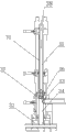
Fig. 1 is the dumpling filling wrapping device structural representation.
Fig. 2 is the dumpling filling wrapping device axonometric drawing.
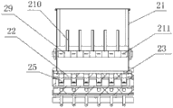
Fig. 3 is filling injecting component of food filling wrapping device structure cutaway view.
Fig. 4 is for filling bucket structure schematic diagram.
Fig. 5 is for filling bucket top view.
Fig. 6 dumpling filling wrapping pushes away filling and cuts leather jacket interposed structure schematic diagram.
Fig. 7 is for pushing away filling block structure schematic diagram.
Fig. 8 is that a plurality of dumpling filling wrappings push away filling and cut leather jacket and put and be arranged side by side structural representation.
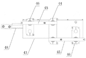
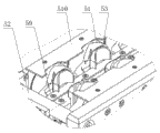
Fig. 9 is the shaft side figure that waits of dumpling filling wrapping device exoperidium shaped device.
Figure 10 is the top view of dumpling filling wrapping device exoperidium shaped device.
Figure 11 is the shaft side figure that waits of a sleeve forming device assembly.
Figure 12 is the front view of transposer.
Figure 13 is the rearview of transposer.
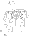
Figure 14 be exoperidium and filling when just having entered to enter dumpling filling shaping mould heart mould be in the partial sectional view of highest order.
Figure 15 is the exoperidium partial sectional view that heart mould mediates when dumpling filling shaping mould effect compacted under.
Figure 16 falls the partial sectional view that Shi Xinmo is in lowest order after exoperidium and filling moulding from heart mould.
Figure 17 is two forming die structure schematic diagrames.
Figure 18 is two die flap structural representations.
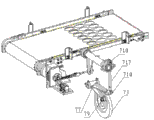
Figure 19 is the top view of conveying mechanism of food encrusting device schematic diagram.
Figure 20 is the upward view of conveying mechanism of food encrusting device structural representation.
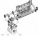
Figure 21 is the driving mechanism of food encrusting device structural representation.
Figure 22 is cam driven swing arm driven member motion structure schematic diagram.
Figure 23 is the chain sprocket structural representation.
Figure 24 is for sending the skin cam and sending skin assembly connection diagram.
Figure 25 is for pushing away the skin cam, cut the skin cam, pushing away the filling cam and push away filling and cut leather jacket and put connection diagram.
Figure 26 is turning cam and exoperidium shaped device connection diagram.
in accompanying drawing 11, dumpling filling wrapping device frame 12, filling injecting component of food filling wrapping device 13, dumpling filling wrapping pushes away filling and cuts leather jacket and put 14, send skin assembly 15, dumpling filling wrapping device exoperidium shaped device 16, conveying mechanism of food encrusting device 17, driving mechanism of food encrusting device 21, with filling bucket 22, annotate filling valve body 23, advance filling passage 24, go out filling passage 25, notes filling chamber 26, rotary valve 27, piston rod passage 28, piston rod 29, sharf 210, stirring vane 211, stuffings-pressing rod 31, push away skin axle 32, cutting knife 33, filling hole 34, rush filling chamber 35, rush filling axle 36, push away filling piece 37, pore 38, air intake 41, mould frame 42, dumpling filling shaping mould 43, transposer 44, transposition sheet 45, connecting rod 46, revolving fragment 47, gear 48, tooth bar 49, groove 410, driving mechanism 51, die flap 52, the axis of guide 53, heart mould 54, baffle plate 55, cushion cap 56, guiding slide plate 57, moving sheet 58, chute 59, connecting rod 510, supporting plate 61, comprise motor 62, fixed mount 63, conveyer belt 64, synchronous pulley 65, movable stand 66, support 67, mobile cylinder 68, pallet 69, guide pad 610, guide post 71, main motor 72, main shaft 73, send skin cam 74, push away skin cam 75, cut skin cam 76, push away filling cam 77, swing arm driven member 78, cam path 79, roller 710, oscillating bearing 711, arm shaft 712, sprocket wheel 713, chain 714, driven shaft 715, turning cam 716, installing plate 717, oscillating bearing connecting rod 718, tightener sprocket.
The specific embodiment
Dumpling filling wrapping device comprises that dumpling filling wrapping device frame 11 and filling injecting component of food filling wrapping device 12, dumpling filling wrapping push away that filling cuts that leather jacket is put 13, sent skin assembly 14, dumpling filling wrapping device exoperidium shaped device 15, conveying mechanism of food encrusting device 16 and driving mechanism of food encrusting device 17, filling injecting component of food filling wrapping device 12 is provided with a plurality of independently tapping channels, and be provided with corresponding with each tapping channel a plurality ofly completed at same station the dumpling filling wrapping that pushes away filling and Qie Pi and pushed away filling and cut leather jacket and put 13; Send skin assembly 14 to be positioned at dumpling filling wrapping and push away filling and cut leather jacket and put 13 belows, send fall skin station and the dumpling filling wrapping of skin assembly 14 to push away filling and cut leather jacket to put 13 stations corresponding; Dumpling filling wrapping device exoperidium shaped device 15 is positioned at and send the skin assembly 14 belows, and it is provided with dumpling filling shaping mould 4242 and corresponding with the skin station that falls on sending skin assembly 14.
Each dumpling filling wrapping pushes away filling and cuts leather jacket and put 13 and be provided with at least a row, often drains into and arranges less three, and dumpling filling wrapping pushes away filling and cuts leather jacket and put 13 and can arrange setting more, and respectively lines up in line distribution or be interspersed.
fillings joins with after in filling bucket 21, with the sharf 29 in filling bucket 21 by the driving mechanism driven rotary, driving mechanism herein can drive for cylinder, also can be cam or 29 rotations of similar means drive sharf, be respectively arranged with a plurality of stirring vanes 210 and stuffings-pressing rod 211 on sharf 29, blade is rectangular paddle, stuffings-pressing rod 211 ends are provided with presses the filling plate, pressing the filling plate is conventional platy structure design, stirring vane 210 can be arranged side by side, a plurality of stuffings-pressing rods 211 also are arranged side by side, stirring vane 210 and stuffings-pressing rod 211 radially form angle at sharf 29, during initial position, stirring vane 210 up, stuffings-pressing rod 211 is 90 degree with its angle, adjacent stirring vane 210 orientations are different, the stirring vane 210 and the stuffings-pressing rod 211 that drive on it in the time of sharf 29 rotation rotate, do reciprocally swinging under dynamic action, filling is stirred and be pushed into discharging opening, because the adjacent orientation of stirring vane 210 is different, so can play the effect of stirring fillings when rotating, stuffings-pressing rod 211 plays when rotating fillings toward the effect that filling passage 23 pushes of advancing of annotating filling valve body 22.
Fillings enters into and annotates filling chamber 25 by advancing filling passage 23, annotate and to be provided with into filling passage 23 in filling valve body 22 and a plurality ofly independently to go out filling passage 24, advance filling passage 23 and respectively go out filling passage 24 junctions to be provided with the rotary valve 26 that can do gyration, rotary valve 26 be connected along its axis direction and the connecting rod 45 that rotated by power drive.When connecting rod 45 reciprocating rotation, the rotary valve 26 on it is also along with moving reciprocatingly.Annotate the filling chamber 25 interior rotary valves 26 piston rod passage 27 interior with annotating filling valve body 22 and be communicated with, be provided with piston rod 28 in piston rod passage 27, piston rod 28 ends are provided with piston.Piston rod 28 and piston play to be inhaled filling and pushes away the filling effect, rotary valve 26 in annotating filling chamber 25 turns to piston rod passage 27 and when advancing 23 connection of filling passage, namely in Fig. 3 during a position, and piston rod 28 motion of turning right, filling just is stored in to be annotated in filling chamber 25 and piston rod passage 27, realizes inhaling the filling purpose; Again turn to when going out filling passage 24 and piston rod passage 27 and be communicated with when annotating filling chamber 25 interior rotary valves 26; be in Fig. 3 during the b position; piston rod 28 is toward moving left; thereby fillings is released out filling passage 24; except the connecting rod 45 that rotates drove rotary valve 26 rotations, other existing means that can reach same effect also belonged to protection scope of the present invention.
When advancing filling passage 23 and annotating filling chamber 25 is set to when a plurality of, each advances filling passage 23 and independently arranges not connectedly, and each is annotated filling chamber 25 and independently arranges not connectedly, and each advances a filling passage notes filling chamber 25 of 23 correspondences and rotary valves 26.This moment fillings from each independent advance filling passage 23 and enter corresponding notes filling valve body 22 after, be pushed into by corresponding rotary valve 26 and go out accordingly filling passage 24, whole notes filling flow process is namely that a plurality of fillings of independently annotating are worked simultaneously.
When advancing filling passage 23 for a plurality of and not connected, notes filling chamber 25 is one, be provided with a rotary valve 26 in notes filling chamber 25, fillings is independently advanced filling passage 23 from each and is entered this and annotate in filling chamber 25, the notes filling chamber 25 of annotating filling valve body 22 inside be one respectively with respectively advance filling passage 23 and go out the through hole that filling passage 24 is communicated with, on the rotary valve 26 that arranges in this through hole, a plurality of breach are arranged, each gap position advances filling passage 23 and goes out filling passage 24 corresponding with each.
When advancing filling passage 23 and annotate filling chamber 25 when respectively being set to one, be provided with a plurality of rotary valves 26 and annotate in the notes filling chamber 25 of filling valve body 22.Fillings enters when annotating filling chamber 25 and without separating into multiply, but whole enter and annotate filling chamber 25 from advancing filling passage 23, annotate filling chamber 25 and be communicated with respectively a plurality of filling passages 24 that go out, annotating a plurality of rotary valves 26 in filling chamber 25 this moment is pushed out to each to fillings by piston rod 28 and goes out filling passage 24, a plurality of rotary valves 26 can unified driving, also can each independent driving.
When advancing filling passage 23 and annotate filling chamber 25 when respectively being set to, annotate and be provided with 26, one rotary valves 26 of a rotary valve in the notes filling chamber 25 of filling valve body 22 and by piston rod 28, fillings be pushed into a plurality of filling passages 24 that go out simultaneously.
dumpling filling wrapping pushes away that filling cuts that leather jacket puts cuts the skin assembly and comprises and push away skin axle 31 and be arranged on the cutting knife 32 that pushes away skin axle 31 bottoms, and cutting knife 32 blade horizontal cross sectional geometry are that two ends are arcs, are connected by two parallel lines between two arcs, pushing away skin axle 31 is hollow shafts, pushes away to have filling hole 33 on skin axle 31, pushes away skin axle 31 inner chambers for rushing filling chamber 34, rush be provided with in filling chamber 34 can move up and down in the chamber rush filling axle 35, fillings is sent into from filling hole 33, driven by driving mechanism this moment, be arranged on cutting knife 32 whereabouts that push away skin axle 31 lower ends, musculus cutaneus is cut into given shape, then driving mechanism drives and to push away skin axle 31 and fall, it is in mould that the musculus cutaneus that send the skin assembly to transmit the below and come is pushed into next station, sending the skin modular construction is prior art, can adopt the structure shown in Figure 24, but be not limited only to this kind structure, meanwhile rushing filling axle 35 descends, the appropriate fillings that to expose from filling hole 33 positions vertically is flushed on the musculus cutaneus that pushes away skin axle 31 belows, complete and push away filling and cut skin work.Rush filling axle 35 and also be hollow shaft, rushing filling axle 35 lower ends is provided with and pushes away filling piece 36, push away filling piece 36 and be piston block, pore 37 is arranged at the piston block bottom, rushes filling axle 35 upper ends and is provided with air intake 38, can connect external inflation device this moment to blowhole 37 inflations, gas can wash out and be attached to the fillings of rushing on filling axle 35 piston blocks when pushing away filling by the pore 37 of piston block bottom, avoids due to long operation, make the sticking glutinous too much fillings of piston block, affect its normal operation; Rush filling axle 35, push away skin axle 31, cutting knife 32 threes' central axes, make whole device operation more stable; Wherein push away skin axle 31, cutting knife 32 and rush filling axle 35 respectively by driven by motor cam drive, each station action sequence relation is by adjustment cam position realization.
Dumpling filling wrapping pushes away filling and cuts leather jacket and put a plurality of being arranged side by side, and each stuffing-inlet is all towards same side, a plurality of fillingss of advancing 23 inputs of filling passage can be pushed away filling simultaneously.
This device driving mechanism is except the form of using the driven by motor cam, and other forms such as cylinder etc. can realize that the mode of identical function is all within this patent protection domain.
two sleeve forming device assemblies of dumpling filling wrapping device exoperidium shaped device, groove 49 by mould frame 41 two ends is arranged on the connecting rod 45 of transposer 43, two connecting rod 45 1 ends are hinged with 44 top and bottom of replacing respectively, the other end is hinged with revolving fragment 46 1 ends that are arranged on 44 both sides of replacing respectively, the middle part that the other end of two revolving fragments 46 and transposition are 44 is provided with the point of rotation, be connected with transmission mechanism on the point of rotation, the point of rotation is gear 47, transmission mechanism is the tooth bar 48 that meshes with gear 47, when transmission mechanism driven rotary point rotates, because connecting rod 45 is connected with the point of rotation, do in the same way alternative expression motion so drive two connecting rods 45, drive simultaneously the shaped device assembly and also do the alternative expression motion, in like manner the point of rotation can be sprocket wheel, transmission mechanism is that chain 713 or the point of rotation are belt wheel, transmission mechanism is belt.Can realize identical function.
When a sleeve forming device assembly moves to the appointment station, molding assembly rests on this station, after fillings and exoperidium enter this cover, transmission mechanism drives the second sleeve forming die assembly position movement to above-mentioned appointment station, receive fillings and exoperidium, first set mould assembly in the process of motion, is completed the shaping work to exoperidium and fillings at this moment, and when the second sleeve forming die assembly arrives the appointment station, in type food is fallen into next station; Then transmission mechanism counter motion, make first set shaped device assembly get back to the appointment station, restart to receive fillings and exoperidium, the second sleeve forming device assembly moves to next station from the direction opposite with first set shaped device assembly, fall in type finished product, constantly alternation.
A plurality of dumpling filling shaping moulds 42 are installed on the mould frame 41 of shaped device assembly, and dumpling filling shaping mould 42 is arranged side by side, and each driving mechanism 410 is positioned at by each mould as cylinder etc.
owing to being provided with supporting plate 510 on die flap 51, exoperidium there is supporting role, when so exoperidium is positioned on mould, can oneself not fall, by the time fillings is pushed to Pi Shanghou, again on the cushion cap 55 of whole two heart moulds 53 that are pushed into mould, each heart mould 53 can be provided with separately cushion cap 55, also can share a bar shaped cushion cap 55 that adapts with permutation length by an a plurality of heart moulds that be listed as 53, owing to also being provided with curved baffle 54 on heart mould 53 cushion caps 55, the outer part of exoperidium can be owing to being blocked the vertical state that is in by baffle plate 54, exposed portions serve surpasses heart mould 53 baffle plate 54 height, and a pair of die flap 51 of dumpling filling shaping mould 42 is in state separately at this moment, catch the heart mould 53 of fillings and skin between two die flaps 51, and be in highest order, its height is highly suitable with die flap 51.
Air cylinder driven heart mould 53, its guiding slide plate 56 along slide mechanism is moved downward, slide mechanism comprises guiding slide plate 56 and moving sheet 57, be a vertical chute 58 in the middle of guiding slide plate 56, both sides are provided with downwards and the chute 58 that extends toward the outside, for example the left side is " Pie " type groove, and the right side grooved is the chute 58 of axisymmetric shape with it.Two cushion cap 55 lower ends coordinate with chute 58, and the upper end is hinged with moving sheet 57 two ends respectively, and moving sheet 57 is subjected to air cylinder driven in the interior movement of vertical chute 58.
stop motion when taking care mould 53 and dropping to baffle plate 54 and can be contained in two die flap 51 cavitys, two die flaps 51 are subjected to air cylinder driven simultaneously, do move toward one another along the axis of guide 52, two die flaps 51 are connected with the axis of guide 52 by connecting rod 59, connecting rod 59 1 ends can be fixedly connected with single die flap 51, also can be connected with a plurality of die flaps 51 of row simultaneously, connecting rod 59 other ends with can with the axis of guide 52 socket, when making die flap 51 drive motion because of cylinder, can take exercises along the axial direction of the axis of guide 52 by connecting rod 59, so two die flaps 51 merge, heart mould 53 is arranged in die flap 51 inner chambers fully at this moment, and the exoperidium that exceeds heart mould 53 baffle plate 54 height partly is incorporated in die flap 51 one-shot formings together, gauffer groove on die flap 51 inner surfaces makes the edge of exoperidium form pleat.
After the food moulding, die flap 51 is subjected to cylinder action, counter motion is disconnected from each other, 53 of heart moulds continue to descend, because guiding slide plate 56 both sides are provided with downwards and the chute 58 that extends toward the outside, two cushion caps 55 are with aroused in interest mould 53 left and right separation under the constraint of chute 58, the molded food product that is positioned on heart mould 53 falls into next station.
When the mould of each sleeve forming device assembly setting was less, only need be connected with the connecting rod 45 of transposer 43 at an end of each shaped device assembly got final product.
Conveying mechanism of food encrusting device, comprise motor 61, two fixed mounts 62 and row's disk component, row's disk component comprises that conveyer belt 63 and 62 of synchronous pulley 64, two fixed mounts are provided with movable stand 65, movable stand 65 is socketed on two fixed mounts 62, be by guide pad 69 thereunder being set, being socketed on the guide post 610 between two fixed mounts 62 specifically, support 66 is arranged on movable stand 65 tops, support 66 is connected with movable stand 65, can move simultaneously with movable stand 65 in the course of the work.The synchronous pulley 64 that is driven by motor 61 is arranged between support 66, adjacent synchronous pulley 64 is fixed by the turning cylinder that two ends are arranged on support 66 side by side, conveyer belt 63 is arranged on synchronous pulley 64, the rotation of synchronous pulley 64 can directly be driven by motor 61, also can be driven by the turning cylinder that motor 61 drives, article two, be provided with pallet 68 on monolateral conveyer belt 63, when support 66 moved along with movable stand 65, the pallet 68 on it also can be along with movement.Be provided with mobile cylinder 67 on movable stand 65, mobile cylinder 67 other ends are fixed on fixed mount 62, and movable stand 65 is by the guide pad 69 on it and guide post 610 sockets, and guide post 610 two ends are separately fixed on two fixed mounts 62.When movable stand 65 moves left and right along with the cylinder intake exhaust process, because its below is socketed with guide post 610, so can guarantee that the moving direction of movable stand 65 is consistent, movable stand 65 is a plate structure, connecting plate two ends can be fixedly connected with support 66.Telescopic-cylinder direction horizontal quadrature is in the direction of conveyer belt motion, drives movable stand 65 motions except adopting the cylinder mode, and the modes such as piston or hydraulic pressure can make structure that the connecting plate similar structures moves left and right all within protection domain of the present invention.
A plurality of molded food products that at every turn fall are all that to arrange be that unit neatly falls, the purpose that conveyer belt moves left and right is the arrangement mode that will change every steak food, from before every row's proper alignment change into every row alignment, adjacent row misplaces mutually, can make like this that respectively to arrange open ended quantity many as far as possible, also shorten simultaneously the distance between each row, thereby all increased the space of placing finished product at the four direction of level, improved the utilization rate of unit are conveyer belt 63 top tray 68.
The groove that can put finished product is arranged on pallet 68, finished product can directly drop in groove, but due to the specification of pallet 68 and the difference of discharging tight ness rating, different pallet 68 is wanted the corresponding different finished product frequency that drops, if change the frequency that drops that pallet 68 specification will be readjusted finished product, affect very much operating efficiency, that adopts that conveying mechanism of the present invention can be according to pallet 68 upper grooves puts to adjust the amplitude that cylinder moves.
be connected with on a kind of main motor 71 main shafts 72 of driving mechanism of food encrusting device and send skin cam 73, push away skin cam 74, cut skin cam 75 and push away filling cam 76, each cam correspondence respectively is provided with swing arm driven member 77, swing arm driven member 77 1 ends are equipped with the roller 79 of motion in cam path 78, one end is connected with oscillating bearing 710, two ends are connected on arm shaft 711 jointly, oscillating bearing 710 arranges corresponding with cam, each cam is driven rotary by the rotation of main motor 71 main shafts 72, rotation simultaneously drives roller 79 due to the shape of its interior grooves and swing arm driven member 77 swings up and down, swing arm driven member 77 swings and drives oscillating bearing 710 motions that are connected with its other end, each oscillating bearing 710 drives each station motion by oscillating bearing connecting rod 717.With each mechanism as sending the skin assembly, pushing away skin axle 31 etc. by using the hinged mode of connecting rod 45 etc. to be connected, thereby drive its motion, and can be in advance the action relationships of each station be set by different cams, only need a main motor 71 just can drive whole device.
be fixed on exoperidium shaped device turning cam 715 on driven shaft 714 also along with driven shaft 714 rotates, turning cam 715 is connected to the transposer 43 of exoperidium shaped device by modes such as hinged even gear 47 bars, thereby realize that transposer 43 does gyration, due to the exoperidium shaped device when the molded food product, in the time of when a shaped device assembly is made in moulding, another set of shaped device assembly is also receiving skin and filling, when first set falls finished product, the second cover rigidly connects receives skin and filling, then transposer 43 is because cam driven moves, with first set and the second cover location swap, the second cover beginning moulding, then fall finished product, first set is got back to the position that receives skin and filling and is received filling and skin, so pushing away filling cuts leather jacket and puts in a workflow, need to cut skin, push away filling, twice of moulding, and 43 work of transposer once, described by adjusting gear 47 sizes of driving shaft and driven shaft 714, main shaft 72 is set to be 2:1 with driven shaft 714 speed ratios.
Send skin cam 73 operation principles to be: to drive main motor 71 and connect driving shaft, skin cam 73 is sent in the driving shaft connection, be contained in cam path 78 by swing arm driven member 77 1 termination rollers 79, one termination oscillating bearing connecting rod 717, when main shaft 72 band moving cam rotation, swing arm swings around arm shaft 711, drives another swing arm and swings and pull chain 713 and driven gear 47, send the motion of skin assembly to complete to send skin thereby drive.
Claims (9)
1. dumpling filling wrapping device, comprise dumpling filling wrapping device frame (11) and filling injecting component of food filling wrapping device (12), dumpling filling wrapping pushes away filling and cuts leather jacket and put (13), send skin assembly (14), dumpling filling wrapping device exoperidium shaped device (15), conveying mechanism of food encrusting device (16) and driving mechanism of food encrusting device (17), it is characterized in that: described filling injecting component of food filling wrapping device (12) is provided with a plurality of independently tapping channels, be provided with corresponding with each tapping channel a plurality ofly completed at same station the dumpling filling wrapping that pushes away filling and Qie Pi and pushed away filling and cut leather jacket and put (13), describedly send skin assembly (14) to be positioned at dumpling filling wrapping to push away filling and cut leather jacket and put (13) below, send fall skin station and the dumpling filling wrapping of skin assembly (14) to push away filling and cut leather jacket to put (13) station corresponding, dumpling filling wrapping device exoperidium shaped device (15) is positioned at and send skin assembly (14) below, and it is provided with dumpling filling shaping mould (42) and corresponding with the skin station that falls on sending skin assembly (14),
Described each dumpling filling wrapping pushes away filling and cuts leather jacket and put (13) and be provided with at least a row, often drains into and arranges less three;
Described dumpling filling wrapping pushes away filling and cuts leather jacket and put (13) and be many rows, and becomes in line distribution or be interspersed;
Filling injecting component of food filling wrapping device (12), comprise with filling bucket (21) and the notes filling valve body (22) that is communicated with it, annotate and to be provided with into filling passage (23) in filling valve bodies (22) and a plurality ofly independently to go out filling passage (24), advance filling passage (23) and respectively go out filling passage (24) junction to be provided with and to annotate filling chamber (25), annotate in filling chambeies (25) and be provided with the rotary valve (26) that to do gyration;
Describedly advance filling passage (23) and annotate filling chambeies (25) for a plurality of, respectively advance filling passage (23) and independently arrange not connectedly, each is annotated filling chamber (25) and independently arranges not connectedly, and each advances notes filling chamber (25) of filling passage (23) correspondence and rotary valve (26);
Or describedly advance filling passage (23) for a plurality of and not connected, annotating filling chambeies (25) is one, annotates in filling chambeies (25) and is provided with rotary valve (26);
Or describedly advance filling passage (23) and annotate filling chambeies (25) respectively to arrange one, the notes filling chamber (25) of annotating in filling valve bodies (22) is provided with a plurality of rotary valves (26);
Or describedly advance filling passage (23) and annotate filling chambeies (25) respectively to arrange one, the notes filling chamber (25) of annotating in filling valve bodies (22) is provided with a rotary valve (26);
Described rotary valve (26) with along its axis direction and be connected by the connecting rod (45) that power drive is rotated, rotary valve (26) in described notes filling chamber (25) the piston rod passage (27) interior with annotating filling valve body (22) is communicated with, be provided with piston rod (28) in piston rod passage (27), described piston rod (28) end is provided with piston;
Described with being provided with sharf (29) in filling bucket (21), be respectively arranged with a plurality of stirring vanes (210) and stuffings-pressing rod (211) on sharf (29), adjacent stirring vane (210) orientation is different, stirring vane (210) radially becomes angle with stuffings-pressing rod (211) at sharf (29), and described stirring vane (210) is rectangular paddle; Stuffings-pressing rod (211) end is provided with presses the filling plate.
2. a kind of dumpling filling wrapping device according to claim 1, it is characterized in that: dumpling filling wrapping pushes away filling and cuts leather jacket and put (13), comprise and cut skin assembly and driving mechanism, cutting the skin assembly comprises and pushes away skin axle (31) and be arranged on the cutting knife (32) that pushes away skin axle (31) bottom, push away skin axle (31) and be hollow shaft, push away having filling hole (33) on skin axle (31), push away skin axle (31) inner chamber for rushing filling chamber (34), rush be provided with in filling chamber (34) can move up and down in the chamber rush filling axle (35); Push away skin axle (31), cutting knife (32) and rush filling axle (35) and driven by driving mechanism respectively, the described filling axle (35) that rushes is hollow shaft, rushing filling axle (35) lower end is provided with and pushes away filling piece (36), pushing away filling piece (36) is piston block, pore (37) is arranged at piston block bottom, rushes filling axle (35) upper end and is provided with air intake (38); Rush filling axle (35), push away skin axle (31), cutting knife (32) three's central axes.
3. a kind of dumpling filling wrapping device according to claim 2 is characterized in that: described dumpling filling wrapping pushes away filling and cuts leather jacket and put (13) many covers and be arranged side by side, and the stuffing-inlet of each covering device is all towards same side; Described cutting knife (32) blade horizontal cross sectional geometry two ends are arcs, are connected by two parallel lines between two arcs; Described driving mechanism is cam driving structure, and each station action sequence relation is by adjustment cam position realization.
4. a kind of dumpling filling wrapping device according to claim 1, it is characterized in that: described dumpling filling wrapping device exoperidium shaped device (15), comprise the shaped device assembly, the shaped device assembly comprises mould frame (41), the driving mechanism (410) that dumpling filling shaping mould (42) and driving dumpling filling shaping mould (42) open and close, described shaped device assembly is provided with up and down two covers, be connected with the exchange transposer (43) of two grip assembly stations up and down on the shaped device assembly, transposer (43) comprises transposition sheet (44) and two connecting rods (45), two connecting rod (45) one ends are hinged with transposition sheet (44) top and bottom respectively, the other end is hinged with revolving fragment (46) one ends that are arranged on transposition sheet (44) both sides respectively, the middle part of the other end of two revolving fragments (46) and transposition sheet (44) is provided with the point of rotation, at least one point of rotation is provided with initiatively transmission mechanism, two sleeve forming device assemblies are arranged on respectively on two connecting rods (45), and the shaped device assembly is arranged on the connecting rod (45) of two transposers (43) by the groove (49) of its mould frame (41) two ends member, on the mould frame (41) of shaped device assembly, a plurality of moulds are installed, mould is arranged side by side, and each driving mechanism (410) is positioned at by each mould.
5. a kind of dumpling filling wrapping device according to claim 4, it is characterized in that: the described point of rotation is gear (47), transmission mechanism is the tooth bar (48) with gear (47) engagement; Or the described point of rotation is sprocket wheel, and transmission mechanism is chain; Or the described point of rotation is belt wheel, and transmission mechanism is belt, and the point of rotation is by the motor shaft driven rotary.
6. a kind of dumpling filling wrapping device according to claim 4, it is characterized in that: described dumpling filling shaping mould (42), comprise left and right two die flaps (51), two die flaps (51) are along the axis of guide (52), driven in opposite directions by driving mechanism (410) or oppositely move, two die flaps (51) corresponding surface and food with filling shape are suitable; The heart mould (53) of two carrying belt filling foods is set, the upper slide mechanism that makes it move up and down and separate that connects of heart mould (53) between two die flaps (51); Heart mould (53) upper end is for being contained in the baffle plate (54) in die flap (51) cavity, and the lower end is the cushion cap (55) of carrying belt filling food; Die flap (51) is connected with the axis of guide (52) by connecting rod (59), and driving mechanism (410) comprises the cylinder that drives heart mould (53) motion and the cylinder that drives die flap (51), and the top of mould is provided with supporting plate (510).
7. a kind of dumpling filling wrapping device according to claim 6 is characterized in that: described slide mechanism comprises guiding slide plate (56) and a moving sheet (57), and guiding slide plate (56) both sides are provided with downwards and toward the chute (58) of outside extension; Described cushion cap (55) lower end coordinates with chute (58), upper end and moving sheet (57) are hinged, moving sheet (57) is moved up and down by driving mechanism (410) driving, and heart mould (53) is realized the left and right separation in the vertical direction motion under the constraint of guiding slide plate (56).
8. a kind of dumpling filling wrapping device according to claim 1, it is characterized in that: conveying mechanism of food encrusting device (16), comprise motor (61), two fixed mounts (62) and row's disk component, row's disk component comprises conveyer belt (63) and synchronous pulley (64), be provided with movable stand (65) between two fixed mounts (62), support (66) is arranged on above movable stand (65), the synchronous pulley (64) that is driven by motor (61) is arranged between support (66), conveyer belt (63) is arranged on synchronous pulley (64), be provided with mobile cylinder (67) on movable stand (65), described mobile cylinder (67) other end is fixed on fixed mount (62), be provided with pallet (68) on described conveyer belt (63), described movable stand (65) is by the guide pad (69) on it and guide post (610) socket, guide post (610) two ends are separately fixed on two fixed mounts (62), described movable stand (65) is a plate, and connecting plate two ends are fixedly connected with support (66).
9. a kind of dumpling filling wrapping device according to claim 1, it is characterized in that: driving mechanism of food encrusting device (17), comprise main motor (71), be provided with on described main motor (71) main shaft (72) and send skin cam (73), push away skin cam (74), cut skin cam (75) and push away filling cam (76), each cam correspondence respectively is provided with swing arm driven member (77), swing arm driven member (77) one ends are equipped with the roller (79) of motion in cam path (78), one end is connected with oscillating bearing (710), swing arm driven member (77) is enclosed within on arm shaft (711), main shaft (72) is provided with sprocket wheel (712), sprocket wheel (712) drives driven shaft (714) by chain (713), be provided with exoperidium shaped device turning cam (715) on driven shaft (714), described main shaft (72) is 2:1 with driven shaft (714) speed ratio, main motor (71) one sides are provided with a plurality of installing plates (716), and the main shaft other end is arranged on installing plate (716), driven shaft (714) is separately fixed on installing plate (716) with arm shaft (711) two ends.
Priority Applications (1)
| Application Number | Priority Date | Filing Date | Title |
|---|---|---|---|
| CN 201010570568 CN102177928B (en) | 2010-12-02 | 2010-12-02 | Food encrusting device |
Applications Claiming Priority (1)
| Application Number | Priority Date | Filing Date | Title |
|---|---|---|---|
| CN 201010570568 CN102177928B (en) | 2010-12-02 | 2010-12-02 | Food encrusting device |
Publications (2)
| Publication Number | Publication Date |
|---|---|
| CN102177928A CN102177928A (en) | 2011-09-14 |
| CN102177928B true CN102177928B (en) | 2013-05-08 |
Family
ID=44564344
Family Applications (1)
| Application Number | Title | Priority Date | Filing Date |
|---|---|---|---|
| CN 201010570568 Active CN102177928B (en) | 2010-12-02 | 2010-12-02 | Food encrusting device |
Country Status (1)
| Country | Link |
|---|---|
| CN (1) | CN102177928B (en) |
Families Citing this family (18)
| Publication number | Priority date | Publication date | Assignee | Title |
|---|---|---|---|---|
| CN103891808B (en) * | 2014-04-25 | 2016-03-02 | 成都松川雷博机械设备有限公司 | Stuffing food forming machine |
| CN104627899B (en) * | 2015-02-04 | 2017-06-30 | 黄骅 | Scissor lift platform |
| US11116226B2 (en) * | 2015-06-08 | 2021-09-14 | Rheon Automatic Machinery Co., Ltd. | Shutter piece |
| CN104904771A (en) * | 2015-07-07 | 2015-09-16 | 成都松川雷博机械设备有限公司 | Rounding encrusting machine |
| CN105145702B (en) * | 2015-08-30 | 2023-08-11 | 金华市喜加达智能设备有限公司 | Stuffing separating device |
| CN105145705B (en) * | 2015-10-26 | 2017-11-07 | 严松法 | The faric station of cat ear dough former |
| CN105360200B (en) * | 2015-11-24 | 2017-11-24 | 李春萍 | Make dumplings device |
| CN105724510B (en) * | 2016-04-28 | 2020-06-02 | 成都松川雷博机械设备有限公司 | Stuffed food forming machine |
| CN106174666B (en) * | 2016-07-07 | 2018-10-26 | 大连智汇达科技有限公司 | Material automatic filling machine |
| CN106689250B (en) * | 2016-12-16 | 2018-12-18 | 重庆市长寿区舒福食品有限公司 | Beef won ton process equipment |
| CN109515881B (en) * | 2017-09-20 | 2023-10-27 | 湖北珍肴食品股份有限公司 | Separating device of packaging machine |
| CN107801742B (en) * | 2017-11-14 | 2020-11-03 | 董官献 | Full-automatic dumpling inclusion equipment |
| CN108782646B (en) * | 2018-08-20 | 2023-10-31 | 山东百越机械科技有限公司 | Dumpling soup forming machine |
| CN109197933A (en) * | 2018-11-12 | 2019-01-15 | 山东百越机械科技有限公司 | Modified Won Ton Forming Machine |
| CN109548817A (en) * | 2018-12-23 | 2019-04-02 | 青岛乐佳食品机械有限公司 | A kind of spring roll wrapping send leather jacket to set |
| CN109548815B (en) * | 2018-12-23 | 2024-01-30 | 青岛乐佳食品机械有限公司 | Full-automatic spring roll wrapping equipment and full-automatic spring roll wrapping method thereof |
| CN113678853B (en) * | 2021-08-01 | 2022-10-04 | 大连妙禾食品配送有限公司 | Dumpling production device capable of achieving rapid extrusion forming and automatic stuffing wrapping |
| CN116638569B (en) * | 2023-06-01 | 2023-10-24 | 北京牛氏运昌(霸州)食品有限公司 | Red date dicing equipment and red date dicing method |
Citations (4)
| Publication number | Priority date | Publication date | Assignee | Title |
|---|---|---|---|---|
| CN101228889A (en) * | 2007-12-27 | 2008-07-30 | 姚强 | Dumpling maker |
| CN201160466Y (en) * | 2008-01-29 | 2008-12-10 | 成都松川雷博机械设备有限公司 | Dumpling making machine |
| CN201216153Y (en) * | 2008-06-05 | 2009-04-08 | 孙发根 | Multiheaded dumpling making machine |
| CN201938292U (en) * | 2010-12-02 | 2011-08-24 | 成都松川雷博机械设备有限公司 | Dumpling filling wrapping device |
Family Cites Families (1)
| Publication number | Priority date | Publication date | Assignee | Title |
|---|---|---|---|---|
| JP3726090B2 (en) * | 2003-05-30 | 2005-12-14 | レオン自動機株式会社 | Wrapping machine |
-
2010
- 2010-12-02 CN CN 201010570568 patent/CN102177928B/en active Active
Patent Citations (4)
| Publication number | Priority date | Publication date | Assignee | Title |
|---|---|---|---|---|
| CN101228889A (en) * | 2007-12-27 | 2008-07-30 | 姚强 | Dumpling maker |
| CN201160466Y (en) * | 2008-01-29 | 2008-12-10 | 成都松川雷博机械设备有限公司 | Dumpling making machine |
| CN201216153Y (en) * | 2008-06-05 | 2009-04-08 | 孙发根 | Multiheaded dumpling making machine |
| CN201938292U (en) * | 2010-12-02 | 2011-08-24 | 成都松川雷博机械设备有限公司 | Dumpling filling wrapping device |
Non-Patent Citations (1)
| Title |
|---|
| JP特开2004-232A 2004.01.08 |
Also Published As
| Publication number | Publication date |
|---|---|
| CN102177928A (en) | 2011-09-14 |
Similar Documents
| Publication | Publication Date | Title |
|---|---|---|
| CN102177928B (en) | Food encrusting device | |
| CN102177925B (en) | Food encrusting method | |
| CN205813431U (en) | The imitative manual dumpling maker of domestic | |
| CN105724507B (en) | Compact stuffing food forming machine | |
| CN105851109B (en) | Straight line connects the compact stuffing food forming machine of skin | |
| CN102894026A (en) | Follow-up stuffing adding twin-cone roller necking-in machine | |
| CN204742401U (en) | Wanton make -up machine | |
| CN202232844U (en) | Automatic dumpling machine | |
| CN105724508B (en) | A kind of compact stuffing food forming machine | |
| CN109006896A (en) | A kind of flour mixing arrangement of machine for deep-fried twisted dough sticks | |
| CN107439627A (en) | Economizing type imitates manual steamed stuffed bun wrapper-rolling machine | |
| CN102177926B (en) | Food forming method | |
| CN201911278U (en) | Filling injecting component of food filling wrapping device | |
| CN105519619A (en) | Device and method for automatically cutting, turning and grabbing triangular-trapezoid pastry in reciprocating manner | |
| CN103875749A (en) | Cat ear biscuit rolling molding unit | |
| CN104886198A (en) | Instant two-layer food forming method | |
| CN102178164B (en) | Food stuffing pushing and wrapper cutting device | |
| CN201938292U (en) | Dumpling filling wrapping device | |
| CN202232839U (en) | Dumpling making machine | |
| CN109006895A (en) | A kind of bionical dough kneading device of machine for deep-fried twisted dough sticks | |
| CN205756904U (en) | Compact stuffing food forming machine | |
| CN108850047B (en) | Household dumpling machine | |
| CN201898831U (en) | Dumpling filling wrapping and pushing and wrapper cutting device | |
| CN204499446U (en) | Enclosed-type imitates manual boiled dumpling handset | |
| CN102885103A (en) | Circulatory rotation device for multilayer stuffed crisp moon cake rotation moulds |
Legal Events
| Date | Code | Title | Description |
|---|---|---|---|
| C06 | Publication | ||
| PB01 | Publication | ||
| C10 | Entry into substantive examination | ||
| SE01 | Entry into force of request for substantive examination | ||
| C14 | Grant of patent or utility model | ||
| GR01 | Patent grant |