CN102168484B - External hanging scaffold and application method thereof - Google Patents
External hanging scaffold and application method thereof Download PDFInfo
- Publication number
- CN102168484B CN102168484B CN2011100820736A CN201110082073A CN102168484B CN 102168484 B CN102168484 B CN 102168484B CN 2011100820736 A CN2011100820736 A CN 2011100820736A CN 201110082073 A CN201110082073 A CN 201110082073A CN 102168484 B CN102168484 B CN 102168484B
- Authority
- CN
- China
- Prior art keywords
- vertical truss
- building
- external scaffolding
- rod member
- support body
- Prior art date
- Legal status (The legal status is an assumption and is not a legal conclusion. Google has not performed a legal analysis and makes no representation as to the accuracy of the status listed.)
- Active
Links
Images


Landscapes
- Conveying And Assembling Of Building Elements In Situ (AREA)
- Movable Scaffolding (AREA)
Abstract
The invention discloses an external hanging scaffold and an application method thereof. The scaffold is built at one time, is attached on a building, adopts a tower crane mounted on a building construction field as elevating power equipment, and comprises a vertical truss, an attaching device and a scaffold body, wherein the scaffold body is connected with the vertical truss which is connected with the attaching device; the attaching device is connected with the building; the attaching device comprises an anti-tilting rod piece positioned on the upper part of the vertical truss and a bearing outrigger positioned on the middle lower part of the vertical truss; and an automatic limiting device is arranged on the bearing outrigger. The application method of the external hanging scaffold comprises the steps of mounting, fixing, elevating and demounting. The external hanging scaffold disclosed by the invention has the advantages of simple structure, convenience for use and extremely good economic and social benefits.
Description
Technical field
The present invention relates to a kind of scaffold of building operations, be specifically related to be applied to the building main body construction stage to play the scaffold of protective action.
Background technology
The domestic in the past external wall of high-rise building material overwhelming majority adopts ceramic tiles, causes the security incident of hurting sb.'s feelings, decreasing thing because frequent generation ceramic tile comes off recently, and is replaced by coating gradually.The best facility of coating application are hanging baskets.Therefore in the exterior wall construction stage, traditional scaffold is also corresponding to be replaced by hanging basket.But in the main body construction stage, not special-purpose before this scaffold.A kind of external scaffolding is arranged in the prior art, and it is set up along the building burst, once sets up moulding, on building, when building rising one deck, adopts tower crane up to promote once for promoting power.For satisfying the carrying needs, be provided with the skeleton of vertical truss as scaffold.Owing to need just can reach through after a while the intensity that can bear big load after building concrete is built, therefore the load-bearing fulcrum of this scaffold should be positioned at vertical truss bottom and is advisable.For preventing that scaffold from toppling, also should be provided with the anti-dumping rod member on vertical truss top.The load-bearing fulcrum uses screw rod through walls to be connected with building or to be connected with the cantilever member that is arranged on building floor or door opening, window opening place with the anti-dumping rod member usually.This scaffolding structure is simple, and is with low cost, has favorable economic benefit.But because building structure has the shear wall structure of sealing usually; If this structure adopts screw rod through walls, personnel must stand in and remove screw rod through walls on the scaffold when scaffold promoted, if scaffold falls at this moment; Security incident will take place, and therefore have major safety risks; And cantilever member be owing to will satisfy the intensity needs, and general section is bigger, if on shear wall opening holes, can cause building structure to weaken, also have disadvantage.Usually have protrusion or recessed structural change in addition on the building facade; When scaffold promotes; Its anti-dumping rod member perhaps accidentally will bump with it or interfere as the primary structure member of load-bearing fulcrum, causes decreasing the generation of thing casualty accident, therefore; The operation of this scaffold is not too convenient, and compliance also haves much room for improvement.
Summary of the invention
The technical problem that the present invention will solve provides a kind of highly versatile; No matter be side bar or balcony or shear wall structure and building facade protrusion occur or recessed structure can conveniently be installed; And simple to operate, avoid occurring the external scaffolding that the lifting state is interfered or collided.
The technical solution adopted for the present invention to solve the technical problems is: a kind of external scaffolding; It is once to set up moulding and attached to serving as the scaffold that promotes power-equipment on the building, with the tower crane that is installed in construction site; Comprise vertical truss, attachment device, support body; Said support body is connected with vertical truss, and said vertical truss connects attachment device, and attachment device connects building; Described attachment device comprises anti-dumping rod member that is positioned at vertical truss top and the withstand leg that is positioned at vertical truss middle and lower part, and it is characterized in that: described anti-dumping rod member is articulated on the vertical truss; Described withstand leg is provided with the automatic spacing device, and said automatic spacing device is rotationally connected withstand leg with vertical truss under the lifting state, and withstand leg is fixedly connected with vertical truss under the attachment state.
Adopt the benefit of said structure to be: when the present invention attached to building on the time, this moment, all deadweight was born by withstand leg with working load, withstand leg is fixedly connected with vertical truss and makes whole shelf be in stable state; When the present invention promotes; Because the anti-dumping rod member is articulated on the vertical bar, and this moment, withstand leg was rotationally connected with vertical truss, therefore can rotate the anti-dumping rod member or withstand leg makes it pack up along vertical truss; Realize vertical-lift smoothly; And need not start the dolly of tower crane, drive the present invention toward away from the direction motion of building to avoid the projective structure on upper strata, so just saved the time and greatly reduced the probability of caring for the security incident generation of generation with building.Described support body can be the steel tube fastener scaffold of using always, also can be the scaffold of the rod member composition of the rim of a bowl formula scaffold or other typing.
Further; A kind of automatic spacing device of withstand leg of the present invention is disclosed; It is characterized in that: on described withstand leg and the vertical truss corresponding position be respectively equipped with/descend to be connected otic placode; On said/the connection otic placode has the same centre of gyration on the horizontal plane down; Described automatic spacing device comprise withstand leg the crossbeam end face, be located at the scotch on the vertical truss otic placode, when vertical truss was in attached to the state on the building, the crossbeam end face that said scotch withstands withstand leg prevented its rotation; When vertical truss was in tower crane lifting state, the axis direction of said withstand leg centre of gyration in deadweight effect lower edge glided and breaks away from scotch.
This structure does not need special machined part, and cost is low, is convenient to make and processing, and is the simplest, practicality.
Further, for strengthening versatility of the present invention, the active plate that described withstand leg is provided with the whole loads of supporting be arranged on building on the drag hook that is connected of ground anchor ring.Like this, when running into shear wall structure, withstand leg can take down active plate, drag hook is inserted be anchored at the ground anchor ring on the shear wall, and formation is articulated and connected to building, satisfies the needs of structural bearing; When running into side bar or balcony beam or being inconvenient to use drag hook on the withstand leg when ground anchor ring on the building is connected, just can be bearing in the building structure with active plate, satisfy stressed needs.Such structure has strengthened the versatility to various building structure greatly, and simple in structure, and is with low cost, makes handling ease, and operation is very easy.
Further, for increasing safety of the present invention, described vertical truss top also is provided with anti-drop device, described anti-drop device comprise the anchor ear that is connected with vertical truss be arranged on building on the drag hook that is connected of ground anchor ring.Like this, when withstand leg lost efficacy owing to contingency, deadweight and the working load born by withstand leg originally can transfer to be born by anti-drop device; When the anti-dumping rod member lost efficacy, anti-drop device can play the effect that prevents that the present invention from toppling equally, thereby heavily insured for the present invention has increased by one.
Another free-revving engine of the present invention provides the application process of top said external scaffolding.
For reaching this purpose, the present invention provides a kind of technical scheme: the application process of external scaffolding as claimed in claim 1 is characterized in that: comprise following steps:
1) establishment constructure scheme is set up along building periphery burst, according to the hoisting power of site operation tower crane, is divided into a plurality of external scaffoldings unit, and each unit comprises the vertical truss of two Pin; Draw the layout plan of external scaffolding, keep the security improvement distance between the adjacent sheet support body, this distance is to be advisable between the 200mm to 400 usually; Confirm the position and the quantity of vertical truss according to layout plan;
2) according to the position of the layout plan described in the step 1) vertical truss, attachment device and support body are installed, support body is connected with vertical truss, flexibly connects through rod member between the adjacent external scaffolding unit;
3) on the construction floor, bury the ground anchor ring underground;
4) through wall connecting rod spare vertical truss or support body are connected with building;
5) along with the rising of building, connect, support body is increased up to arriving design height with the scaffold rod member;
6) connect the top of the vertical truss of two Pin with the wire rope of tower crane suspension hook, the flexible connection rod member between wall connecting rod spare and the adjacent external scaffolding unit is removed in the stressed back of wire rope, starts the tower crane hoisting mechanism, and plug-in protective frame is promoted first floor;
7) after lifting puts in place, the withstand leg in the attachment device is connected with building respectively with the anti-dumping rod member;
8) the external scaffolding wire rope that lifting is put in place takes off, and carries out between the adjacent external scaffolding unit that lifting is put in place flexibly connecting through rod member, and the wall connecting rod spare that is connected with building is installed, the stability of enhancing external scaffolding unit.
9) bury the ground anchor ring underground at the construction floor;
10) repeating step 6) to step 9, finish until building main body construction, with tower crane external scaffolding unit handling to ground is removed.
This external scaffolding application process operation is very simple, is applicable to the building of various structures, and the workman constructs in building, and labour intensity is little, and it is high to promote efficient, installs and removes and all on ground or floor face, carry out, and safety is secure.
Description of drawings
Fig. 1 is a structural representation of the present invention;
Fig. 2 is the I enlarged diagram of Fig. 1;
Fig. 3 is the II enlarged diagram of Fig. 1;
Fig. 4 is the partial structurtes sketch map of withstand leg of the present invention;
Fig. 5 is the A enlarged diagram among Fig. 4;
Fig. 6 is the local enlarged diagram that withstand leg of the present invention is positioned at building side bar or balcony beam;
Fig. 7 is the local enlarged diagram that anti-dumping rod member of the present invention and anti-drop device are positioned at building side bar or balcony beam;
Fig. 8 is the local enlarged diagram that vertical truss of the present invention is positioned at the two eaves board positions of building;
Fig. 9 is the local enlarged diagram that vertical truss of the present invention is positioned at building shear wall position;
Below in conjunction with the accompanying drawing and the specific embodiment the present invention is done further explanation.
The specific embodiment
As shown in Figure 1; Leger 1 is connected with vertical truss 8 through fastener with the support body that vertical rod 2 is formed; Its outer facade is equipped with close order safety net 3, and support body top connects vertical truss 8 with brace 4 through fastener, is provided with the member that ground anchor ring 5 is connected with building as the present invention at the building facade.Between 6 layings of horizontal safety net and support body bottom and the building, prevent object bottom from the high falling to the support body.The present invention sets up along building periphery burst, and every is provided with two vertical truss, forms stable scaffolding structure through connecting cross bar 7 between the vertical truss.Anti-dumping rod member 9 is provided with otic placode, is connected with otic placode on the vertical truss 8 through bearing pin, and it is hinged that formation can horizontally rotate.Below vertical truss 8; Row's vertical rod 15 in also connecting through fastener; In row's vertical rod 15 and vertical rod 2 through interior row's leger 17 with efflux leger 18 usefulness fasteners and connect to form double support body, be equipped with bamboo springboard 19 closed materials such as grade on it, prevent that object from down falling from scaffold.For increasing stability, brace 16 connects inside and outside framed bent body through fastener respectively.Bottom wall connecting rod 20 drawknots are on the ground anchor ring that is located on the building.
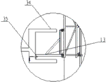
In Fig. 2, an end crotch of flower basket bolt 10 is on ground anchor ring 21, and anchor ring 21 1 ends in ground are anchored on the building.The other end of flower basket bolt 10 is hooked on the ring of draw ring 11, and the other end of draw ring 11 is connected in the vertical rod of vertical truss 8 through anchor ear.
Among Fig. 3, the crotch 23 of withstand leg 13 hooks in the ground anchor ring 21.Be respectively equipped with otic placode on withstand leg 13 and the vertical truss 8 among Fig. 4, be connected with bearing pin 25 through bearing pin 24 respectively.The axis extended line of bearing pin 24 and bearing pin 25 overlaps and withstand leg 13 can be rotated around vertical truss 8.Fig. 5 has provided the structural representation of the automatic spacing device of withstand leg 13.On the otic placode of vertical truss 8, be provided with the part scotch 26 of protrusion among Fig. 5; Withstand leg 13 can slide up and down along bearing pin 25; Under lifting state shown in Figure 5; The crossbeam end face 27 of withstand leg 13 is thrown off scotch 26 toward lower slider under the deadweight effect, this moment, withstand leg 13 can be avoided the ridge on upper strata around vertical truss rotation, such as the last eaves board 34 shown in Fig. 8.Thereby realization vertical-lift.When the present invention is in attachment state; Vertical truss 8 makes scotch 26 insert crossbeam end face 27 1 sides to lower slider under the deadweight effect; Only leave the gap of 0.2mm to about the 0.5mm between the two; The angle of the rotation of withstand leg 13 just is limited like this, and the existence of this gap makes the vertical relatively truss 8 of withstand leg 13 can swing an angle slightly, buries the situation that deviation occurs underground so that withstand leg 13 can adapt to the ground anchor ring 21 shown in Fig. 3.What Fig. 6 provided is the fixing situation of withstand leg 13 on building side bar or balcony beam.Active plate 28 is connected on the withstand leg 13 through bolt 29 among Fig. 6, and active plate 28 is bearing on building side bar or the balcony beam.In Fig. 7, anti-drop device 31 connects vertical truss 8 through anchor ear, and the other end connects flower basket bolt 30, and flower basket bolt 30 hooks in microcephaly's the hole of bquster 32 that profile is a wedge shape, and bquster 32 penetrates in the ground anchor ring 33 that is anchored on the floor face.The effect of flower basket bolt 30 is to be convenient to adjust length, can conveniently install or remove.In Fig. 8 and Fig. 9, show the situation that vertical truss is positioned at two eaves boards and shear wall respectively.In both of these case, the active plate of withstand leg 13 is removed, and its drag hook insertion is anchored at the ground anchor ring 35 on the building and fixes.
Illustrate the application process of a kind of external scaffolding of the present invention below: comprise following steps: 1) establishment constructure scheme; Set up along building periphery burst; According to the hoisting power of site operation tower crane, be divided into a plurality of external scaffoldings unit, each unit comprises the vertical truss of two Pin; Draw the layout plan of external scaffolding, keep the security improvement distance between the adjacent sheet support body, this distance is to be advisable between the 200mm to 400 usually; Confirm the position and the quantity of vertical truss according to layout plan;
2) according to the position of the layout plan described in the step 1) vertical truss, attachment device and support body are installed, support body is connected with vertical truss, flexibly connects through rod member between the adjacent external scaffolding unit;
3) on the construction floor, bury the ground anchor ring underground;
4) through wall connecting rod spare vertical truss or support body are connected with building;
5) along with the rising of building, connect, support body is increased up to arriving design height with the scaffold rod member;
6) connect the top of the vertical truss of two Pin with the wire rope of tower crane suspension hook, the flexible connection rod member between wall connecting rod spare and the adjacent external scaffolding unit is removed in the stressed back of wire rope, starts the tower crane hoisting mechanism, and plug-in protective frame is promoted first floor;
7) after lifting puts in place, the withstand leg in the attachment device is connected with building respectively with the anti-dumping rod member;
8) the external scaffolding wire rope that lifting is put in place takes off, and carries out between the adjacent external scaffolding unit that lifting is put in place flexibly connecting through rod member, and the wall connecting rod spare that is connected with building is installed, the stability of enhancing external scaffolding unit.
9) bury the ground anchor ring underground at the construction floor;
10) repeating step 6) to step 9, finish until building main body construction, with tower crane external scaffolding unit handling to ground is removed.
Specify, as external scaffolding directly on flooring or ground, directly set up and when needing unsettled setting up, can set up the mounting platform of external scaffolding as follows:
A buries the ground anchor ring before the concrete pouring underground after the floor bar colligation is good, attentively anchor ring should be through at the bottom of the floor under the muscle, and good with Zha Si and floor bar colligation.Ground anchor ring burial place apart from side bar 1.5m about, spacing 1.8m
-2.0m;
It is 2m that B chooses length
---The steel pipe of 6m is as sweeping the floor bar.The bar of vertically sweeping the floor penetrates in the ground anchor ring, uses the sub-wedging of timber wedge.The bar of vertically sweeping the floor is used clasp is joined end to end each other, and the local right-angle coupler that adopts of corner connects, and forms an integral body.Rod penetrates the bar below of vertically sweeping the floor, and adopts right-angle coupler to be connected with the bar of vertically sweeping the floor, and exceeds the building distance and is no less than 1.8m, uses flitch to level up at the rod front end.
C selects the steel pipe of corresponding specification as pylon bottom leger, uses two right-angle couplers to be connected with rod at its two ends, is fixed on this leger on the rod.
D connects diagonal brace steel pipe and leger with fastener, and the diagonal brace steel pipe other end is bearing on the floor face of next floor.
Above embodiment only explains concrete application of the present invention; Can not be interpreted as qualification to protection domain of the present invention; So long as adopt technical scheme of the present invention; Perhaps only be to change or distortion, all fall among protection scope of the present invention through the routine that those of ordinary skill in the art can both make.
Claims (4)
1. external scaffolding; It is once to set up moulding and attached to serving as the scaffold that promotes power-equipment on the building, with the tower crane that is installed in construction site; Comprise vertical truss, attachment device, support body; Said support body is connected with vertical truss, and said vertical truss connects attachment device, and attachment device connects building; Described attachment device comprises anti-dumping rod member that is positioned at vertical truss top and the withstand leg that is positioned at vertical truss middle and lower part, and it is characterized in that: described anti-dumping rod member is articulated on the vertical truss; Described withstand leg is provided with the automatic spacing device; Said automatic spacing device is rotationally connected withstand leg with vertical truss under the lifting state; And withstand leg is fixedly connected with vertical truss under the attachment state; On described withstand leg and the vertical truss corresponding position be respectively equipped with/descend is connected otic placode, said on/time connection otic placode has the same centre of gyration on the horizontal plane, described automatic spacing device comprise withstand leg the crossbeam end face, be located at the scotch on the vertical truss otic placode; When vertical truss was in attached to the state on the building, the crossbeam end face that said scotch withstands withstand leg prevented its rotation; When vertical truss was in tower crane lifting state, the axis direction of said withstand leg centre of gyration in deadweight effect lower edge glided and breaks away from scotch.
2. external scaffolding as claimed in claim 1 is characterized in that: the active plate that described withstand leg is provided with the whole loads of supporting be arranged on building on the drag hook that is connected of ground anchor ring; Said anti-dumping rod member be provided be arranged on building on groove/drag hook of being connected of ground anchor ring.
3. external scaffolding as claimed in claim 1 is characterized in that: also be provided with anti-drop device on the described vertical truss, described anti-drop device comprise the anchor ear that is connected with vertical truss be arranged on building on the drag hook that is connected of ground anchor ring.
4. the application process of external scaffolding as claimed in claim 1 is characterized in that: comprise following steps:
1) establishment constructure scheme is set up along building periphery burst, according to the hoisting power of site operation tower crane, is divided into a plurality of external scaffoldings unit, and each unit comprises the vertical truss of two Pin; Draw the layout plan of external scaffolding, keep the security improvement distance between the adjacent sheet support body, this distance is to be advisable between the 200mm to 400 usually; Confirm the position and the quantity of vertical truss according to layout plan;
2) according to the position of the layout plan described in the step 1) vertical truss, attachment device and support body are installed, support body is connected with vertical truss, flexibly connects through rod member between the adjacent external scaffolding unit;
3) on the construction floor, bury the ground anchor ring underground;
4) through wall connecting rod spare vertical truss or support body are connected with building;
5) along with the rising of building, connect, support body is increased up to arriving design height with the scaffold rod member;
6) connect the top of the vertical truss of two Pin with the wire rope of tower crane suspension hook, the flexible connection rod member between wall connecting rod spare and the adjacent external scaffolding unit is removed in the stressed back of wire rope, starts the tower crane hoisting mechanism, and plug-in protective frame is promoted first floor;
7) after lifting puts in place, the withstand leg in the attachment device is connected with building respectively with the anti-dumping rod member;
8) the external scaffolding wire rope that lifting is put in place takes off, and carries out between the adjacent external scaffolding unit that lifting is put in place flexibly connecting through rod member, and the wall connecting rod spare that is connected with building is installed, the stability of enhancing external scaffolding unit;
9) bury the ground anchor ring underground at the construction floor;
10) repeating step 6) to step 9, finish until building main body construction, with tower crane external scaffolding unit handling to ground is removed.
Priority Applications (1)
| Application Number | Priority Date | Filing Date | Title |
|---|---|---|---|
| CN2011100820736A CN102168484B (en) | 2011-04-01 | 2011-04-01 | External hanging scaffold and application method thereof |
Applications Claiming Priority (1)
| Application Number | Priority Date | Filing Date | Title |
|---|---|---|---|
| CN2011100820736A CN102168484B (en) | 2011-04-01 | 2011-04-01 | External hanging scaffold and application method thereof |
Publications (2)
| Publication Number | Publication Date |
|---|---|
| CN102168484A CN102168484A (en) | 2011-08-31 |
| CN102168484B true CN102168484B (en) | 2012-11-14 |
Family
ID=44489788
Family Applications (1)
| Application Number | Title | Priority Date | Filing Date |
|---|---|---|---|
| CN2011100820736A Active CN102168484B (en) | 2011-04-01 | 2011-04-01 | External hanging scaffold and application method thereof |
Country Status (1)
| Country | Link |
|---|---|
| CN (1) | CN102168484B (en) |
Families Citing this family (7)
| Publication number | Priority date | Publication date | Assignee | Title |
|---|---|---|---|---|
| CN102561716A (en) * | 2012-02-29 | 2012-07-11 | 姚磊 | Construction protecting rack |
| CN103407918B (en) * | 2012-12-30 | 2016-03-23 | 上海庞源机械租赁股份有限公司 | The securing device of crane arm unstability and assembling mode thereof under prevention Condition of Sudden Unloading condition |
| CN103899019B (en) * | 2014-03-26 | 2017-01-11 | 湖南省金为型材有限公司 | Curtain wall system |
| CN106677509A (en) * | 2017-02-14 | 2017-05-17 | 中天建设集团有限公司 | Design finalization external protective frame system used for assembly type building construction |
| CN110512853B (en) * | 2019-08-06 | 2023-10-27 | 上海建工一建集团有限公司 | Externally hung protective frame and application method thereof in high-rise building |
| CN110512854A (en) * | 2019-08-06 | 2019-11-29 | 上海建工一建集团有限公司 | A kind of adjustable fastening tool formula externally-hung protective frame system and construction techniques |
| CN113175203A (en) * | 2021-05-07 | 2021-07-27 | 苏茂兵 | Method for setting lifting power equipment in attached lifting scaffold |
Citations (3)
| Publication number | Priority date | Publication date | Assignee | Title |
|---|---|---|---|---|
| CN2101067U (en) * | 1991-03-27 | 1992-04-08 | 江苏省南通市第四建筑安装工程公司 | Externally hung lifting scaffold |
| CN1786385A (en) * | 2005-12-14 | 2006-06-14 | 姚康华 | Protective frame special for construction of building main body |
| CN202055504U (en) * | 2011-04-01 | 2011-11-30 | 姚康华 | Externally-hung scaffold |
Family Cites Families (2)
| Publication number | Priority date | Publication date | Assignee | Title |
|---|---|---|---|---|
| JPH0312024A (en) * | 1989-06-07 | 1991-01-21 | Hitachi Maxell Ltd | Magnetic recording medium |
| JP2975293B2 (en) * | 1995-10-20 | 1999-11-10 | 株式会社ナカオ | Temporary swing stopper |
-
2011
- 2011-04-01 CN CN2011100820736A patent/CN102168484B/en active Active
Patent Citations (3)
| Publication number | Priority date | Publication date | Assignee | Title |
|---|---|---|---|---|
| CN2101067U (en) * | 1991-03-27 | 1992-04-08 | 江苏省南通市第四建筑安装工程公司 | Externally hung lifting scaffold |
| CN1786385A (en) * | 2005-12-14 | 2006-06-14 | 姚康华 | Protective frame special for construction of building main body |
| CN202055504U (en) * | 2011-04-01 | 2011-11-30 | 姚康华 | Externally-hung scaffold |
Also Published As
| Publication number | Publication date |
|---|---|
| CN102168484A (en) | 2011-08-31 |
Similar Documents
| Publication | Publication Date | Title |
|---|---|---|
| CN102168484B (en) | External hanging scaffold and application method thereof | |
| CN105971271B (en) | Unilateral cantilever form and its construction method of climbing certainly | |
| CN102383588B (en) | Lifting platform for protecting safety of high-level construction | |
| CN201598820U (en) | Single-point suspension external hanging rack | |
| CN202023360U (en) | Hydraulic climbing die plate for building construction | |
| CN103993728B (en) | A kind of assembling shaped steel is encorbelmented protection canopy | |
| CN214195484U (en) | All-steel attached lifting scaffold | |
| CN202055504U (en) | Externally-hung scaffold | |
| CN203891441U (en) | Assembly type section steel overhung protective shed | |
| CN105350760B (en) | A kind of construction method of suspending scaffold | |
| CN203113793U (en) | Large formwork installation system of oblique structure | |
| CN205171979U (en) | Integrated form all steel lift platform | |
| CN107587711A (en) | A kind of regularization assembled overhanging protection canopy and its assembly method | |
| CN101701492A (en) | Guide rail frame type adhering lifting scaffold | |
| CN202000647U (en) | Base device for lifting scaffold in elevator shaft | |
| CN201502170U (en) | Horizontal supporting device of building external frame | |
| CN212406038U (en) | Lower hanging construction platform module of high-altitude large-cantilever steel roof truss | |
| CN205134921U (en) | Building outer wall concrete constructional column hangs construction platform | |
| CN204212388U (en) | Monolithic combined scaffold | |
| CN204754150U (en) | Dish -type node formula scaffold | |
| CN203022327U (en) | Elevator shaft high-altitude construction platform device | |
| CN209651673U (en) | A kind of construction elevator attaching structure of lifting platform | |
| CN113445723A (en) | Construction platform for mounting overhanging structure curtain wall and mounting method | |
| CN209556330U (en) | Construction operation platform for elevator | |
| CN201053199Y (en) | Large template pylon |
Legal Events
| Date | Code | Title | Description |
|---|---|---|---|
| C06 | Publication | ||
| PB01 | Publication | ||
| C10 | Entry into substantive examination | ||
| SE01 | Entry into force of request for substantive examination | ||
| C14 | Grant of patent or utility model | ||
| GR01 | Patent grant |