CN101944780B - Contactless power receiving apparatus, power receiving method for contactless power receiving apparatus and contactless power supplying system - Google Patents
Contactless power receiving apparatus, power receiving method for contactless power receiving apparatus and contactless power supplying system Download PDFInfo
- Publication number
- CN101944780B CN101944780B CN2010102221689A CN201010222168A CN101944780B CN 101944780 B CN101944780 B CN 101944780B CN 2010102221689 A CN2010102221689 A CN 2010102221689A CN 201010222168 A CN201010222168 A CN 201010222168A CN 101944780 B CN101944780 B CN 101944780B
- Authority
- CN
- China
- Prior art keywords
- electric power
- destination
- noncontact
- receiving apparatus
- power supply
- Prior art date
- Legal status (The legal status is an assumption and is not a legal conclusion. Google has not performed a legal analysis and makes no representation as to the accuracy of the status listed.)
- Active
Links
Images


Classifications
-
- H—ELECTRICITY
- H02—GENERATION; CONVERSION OR DISTRIBUTION OF ELECTRIC POWER
- H02J—CIRCUIT ARRANGEMENTS OR SYSTEMS FOR SUPPLYING OR DISTRIBUTING ELECTRIC POWER; SYSTEMS FOR STORING ELECTRIC ENERGY
- H02J7/00—Circuit arrangements for charging or depolarising batteries or for supplying loads from batteries
- H02J7/00032—Circuit arrangements for charging or depolarising batteries or for supplying loads from batteries characterised by data exchange
- H02J7/00034—Charger exchanging data with an electronic device, i.e. telephone, whose internal battery is under charge
-
- H—ELECTRICITY
- H02—GENERATION; CONVERSION OR DISTRIBUTION OF ELECTRIC POWER
- H02J—CIRCUIT ARRANGEMENTS OR SYSTEMS FOR SUPPLYING OR DISTRIBUTING ELECTRIC POWER; SYSTEMS FOR STORING ELECTRIC ENERGY
- H02J50/00—Circuit arrangements or systems for wireless supply or distribution of electric power
- H02J50/10—Circuit arrangements or systems for wireless supply or distribution of electric power using inductive coupling
- H02J50/12—Circuit arrangements or systems for wireless supply or distribution of electric power using inductive coupling of the resonant type
-
- H—ELECTRICITY
- H02—GENERATION; CONVERSION OR DISTRIBUTION OF ELECTRIC POWER
- H02J—CIRCUIT ARRANGEMENTS OR SYSTEMS FOR SUPPLYING OR DISTRIBUTING ELECTRIC POWER; SYSTEMS FOR STORING ELECTRIC ENERGY
- H02J50/00—Circuit arrangements or systems for wireless supply or distribution of electric power
- H02J50/40—Circuit arrangements or systems for wireless supply or distribution of electric power using two or more transmitting or receiving devices
-
- H—ELECTRICITY
- H02—GENERATION; CONVERSION OR DISTRIBUTION OF ELECTRIC POWER
- H02J—CIRCUIT ARRANGEMENTS OR SYSTEMS FOR SUPPLYING OR DISTRIBUTING ELECTRIC POWER; SYSTEMS FOR STORING ELECTRIC ENERGY
- H02J50/00—Circuit arrangements or systems for wireless supply or distribution of electric power
- H02J50/80—Circuit arrangements or systems for wireless supply or distribution of electric power involving the exchange of data, concerning supply or distribution of electric power, between transmitting devices and receiving devices
-
- H—ELECTRICITY
- H02—GENERATION; CONVERSION OR DISTRIBUTION OF ELECTRIC POWER
- H02J—CIRCUIT ARRANGEMENTS OR SYSTEMS FOR SUPPLYING OR DISTRIBUTING ELECTRIC POWER; SYSTEMS FOR STORING ELECTRIC ENERGY
- H02J1/00—Circuit arrangements for dc mains or dc distribution networks
- H02J1/14—Balancing the load in a network
-
- H—ELECTRICITY
- H02—GENERATION; CONVERSION OR DISTRIBUTION OF ELECTRIC POWER
- H02J—CIRCUIT ARRANGEMENTS OR SYSTEMS FOR SUPPLYING OR DISTRIBUTING ELECTRIC POWER; SYSTEMS FOR STORING ELECTRIC ENERGY
- H02J2310/00—The network for supplying or distributing electric power characterised by its spatial reach or by the load
- H02J2310/50—The network for supplying or distributing electric power characterised by its spatial reach or by the load for selectively controlling the operation of the loads
- H02J2310/56—The network for supplying or distributing electric power characterised by its spatial reach or by the load for selectively controlling the operation of the loads characterised by the condition upon which the selective controlling is based
- H02J2310/58—The condition being electrical
- H02J2310/60—Limiting power consumption in the network or in one section of the network, e.g. load shedding or peak shaving
Landscapes
- Engineering & Computer Science (AREA)
- Power Engineering (AREA)
- Computer Networks & Wireless Communication (AREA)
- Charge And Discharge Circuits For Batteries Or The Like (AREA)
- Current-Collector Devices For Electrically Propelled Vehicles (AREA)
Abstract
Disclosed herein is a contactless power receiving apparatus, including a resonance element adapted to receive supply of AC power in a contactless fashion by resonance from a resonance element of a power supplying source; an excitation element adapted to receive supply of the AC power by electromagnetic induction from the resonance element; a rectification circuit adapted to generate DC power from the AC power from the excitation element and output the DC power; and a changeover circuit adapted to change over the AC power between a supplied state and a non-supplied state to the rectification circuit.
Description
Technical field
The present invention relates to for use magnetic field resonance receive the noncontact power receiving apparatus of the supply of electric power, for the power reception method of this noncontact power receiving apparatus and the noncontact electric power supply system that has been incorporated to described noncontact power receiving apparatus and described power reception method.
Background technology
As send the technology of electric energy with the noncontact form for permission, electromagnetic induction method and magnetic field resonance method are available.Electromagnetic induction method and magnetic field resonance method have each such species diversity as described below, and in recent years, pay close attention to the energy that uses the magnetic field resonance method and send.
Fig. 9 illustrates the example of configuration of the noncontact electric power supply system of magnetic field resonant type, and wherein, electric power supply source and electric power are supplied with object or destination corresponds to each other with man-to-man corresponding relation.With reference to Fig. 9, the noncontact electric power supply device of shown magnetic field resonant type comprises electric power supply source 100 and electric power supply destination 200.
As shown in Figure 9, electric power supply source 100 can be for example charging bracket (cradle), and comprises AC (interchange) power supply 101, exciting element 102 and resonant element 103.Simultaneously, it can be portable telephone terminal that electric power is supplied with destination 200, and comprises resonant element 201, exciting element 202 and rectification circuit 203.
The exciting element 102 of electric power supply source and resonant element 103 and electric power are supplied with the resonant element 201 of destination and each in exciting element 202 forms by air core coil (air-core coil).In the inside of electric power supply source 100, exciting element 102 and resonant element 103 close coupling each other by electromagnetic induction.Similarly, supply with the inside of destination 200 at electric power, resonant element 201 and exciting element 202 close coupling each other by electromagnetic induction.
When the self-resonant frequency of the resonant element 201 of the air core coil form of supplying with destination 200 when resonant element 103 and the electric power of the air core coil form of electric power supply source 100 is consistent with each other, resonant element 103 and resonant element 201 are placed into coupling amount maximum and the magnetic field resonance relation of loss minimum.
Particularly, the noncontact electric power supply system shown in Fig. 9 is worked in the following manner.Particularly, at first in the electric power supply source, to offer exciting element 102 as the AC electric power AC electric current, preset frequency from AC power supplies 101, in exciting element 102, the electromagnetic induction by AC electric power induces the AC electric power for resonant element 103.The frequency of the AC electric power generated in AC power supplies 101 here, equals the resonant element 103 of electric power supply source and the self-resonant frequency that electric power is supplied with the resonant element 201 of destination.
As mentioned above, the resonant element 201 of the resonant element 103 of electric power supply source and electric power supply destination is arranged with magnetic field resonance relation.Therefore, utilize resonance frequency, with the noncontact form, AC electric power is provided to resonant element 201 from resonant element 103.
Supply with in destination 200 the AC electric power of being accepted from the resonant element 103 of electric power supply source by resonant element 201 at electric power.By electromagnetic induction, be provided to rectification circuit 203 via exciting element 202 from the AC electric power of resonant element 201, and change and be output as DC (direct current) electric power through rectification circuit 203.
Like this, with the noncontact form, AC electric power is provided to the electric power destination from the electric power supply source.Note, will for example provide the charging circuit be connected to battery from the DC electric power of rectification circuit 203 outputs, in order to use it for, battery is charged.
Supply with destination with the top electric power supply source configured in conjunction with the described this mode of Fig. 9 and electric power and there is following properties with the noncontact electric power supply system corresponded to each other by one-to-one correspondence.
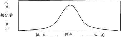
The noncontact electric power supply system has such as shown in Figure 10 A relation between the frequency of AC electric power and coupling amount.As from can seeing Figure 10 A, even the frequency of AC electric power is very low or very high on the contrary, the coupling amount is not high yet, but only presents its maximum on the preset frequency that the magnetic field resonance phenomena occurs.In other words, coupling amount is the frequence of exposure selectivity according to magnetic field resonance.
Further, the noncontact electric power supply system has such as shown in Figure 10 B relation between resonant element 103 and 201 s' distance and coupling amount.As from can seeing Figure 10 B, the coupling amount reduces along with the increase of distance between resonant element.
Yet, even the distance between resonant element is very little, the coupling amount is also not necessarily very large, but, on particular resonant frequency, the coupling amount presents maximum at specific range.Further, from Figure 10 B, can see, if the distance between resonant element remains in a certain scope, can guarantee higher than the fixing coupling amount of rank (level).
Further, the noncontact electric power supply system is in resonance frequency and obtained between the distance between the resonant element of maximum coupling amount and have the relation as shown in Figure 10 C.From Figure 10 C, can see, in the situation that resonance frequency is very low, the distance between resonant element is very large.Can see in addition, in the situation that resonance frequency is very high, by the distance reduced between resonant element, obtain maximum coupling amount.
In the noncontact electric power supply system of current widely used electromagnetic induction type, electric power supply source and electric power provide destination need to share magnetic flux, and, in order effectively to send electric power, electric power supply source and electric power provide destination to arrange close to each other.In addition, the axial registration (axial registration) that electric power supply source that be coupled to each other and electric power provide destination is important.
Simultaneously, use the advantage of the noncontact electric power supply system of magnetic field resonance phenomena to be: in the noncontact electric power supply system, than passing through the electromagnetic induction method, can on larger distance, send electric power, in addition, even axially registration is not very good, transmitting efficiency can not descend much yet.
According to above-mentioned, the noncontact electric power supply system of magnetic field resonant type and the noncontact electric power supply system of electromagnetic induction type have these difference as listed as Figure 11.Particularly, as seen in Figure 11, the noncontact electric power supply system of magnetic field resonant type is difficult to impact with respect to the displacement of (that is, between resonant element) between the sending and receiving coil, and allows the transmission range of more growing.
Therefore, the noncontact electric power supply system of magnetic field resonant type can carry out the electric power supply in the mode that Figure 12 was seen.Particularly, with reference to Figure 12, the electric power that a plurality of electric power supplies destination of the portable terminal in Figure 12 can be placed in Figure 12 is supplied with on the single electric power supply source of support, thereby by the latter, they is charged.
Yet electric power supply source or electric power are supplied with a plurality of electric power supply destination or the portable terminal placed on support may comprise electric power supply destination as follows: it should have precedence over other electric power and supplies with destination and charged rapidly; Perhaps may comprise that electric power as follows supplies with destination: it for example can be before daystart be used it subsequently and be recharged.
As can priority by this way supplying with to a plurality of electric power the existing system charged in destination, the batteries charging adapter of contact-type is disclosed in Japanese Patent Laid-Open No.2004-207137 (hereinafter being referred to as patent documentation 1).
In patent documentation 1, disclosed batteries charging adapter can be charged to a plurality of battery pack simultaneously, and comprise not concrete disclosed preferential switching part in patent documentation 1 of configuration, so that it has the function that the priority of charging is applied to connected battery pack.
Further, as the noncontact electric power supply system, the charging device (although priority is applied to electric power, not supplying with destination) for the contactless portable communication equipment of electromagnetic induction type is disclosed in Japanese Patent Laid-Open No.Hei 11-168837 (hereinafter being referred to as patent documentation 2).
The disclosed charging device for the contactless portable communication equipment in patent documentation 2, in order to prevent between charge period the bad interference for the traffic operation of portable communication device, based on indication, to carry out from the information in moment of the communication of portable communication device and on/off is supplied with from the electric power of charging device.
Utilize the disclosed charging device for the contactless portable communication equipment in patent documentation 2, although priority is applied to as described above to electric power, do not supply with destination, in fact charging device can control the charged state of portable communication device.
Summary of the invention
Incidentally, in patent documentation 1, in the batteries charging adapter of disclosed contact-type, charging adapter one side be connected with a plurality of battery pack physically by splicing ear when being used is controlled the priority for connected battery pack is charged.
Supply with a side (that is, in power shelf one side) with reference to the electric power of figure 9 described configurations having above, for each portable electric appts of placing on it, do not provide resonant element.Therefore, in the noncontact electric power supply system with the top magnetic field resonant type that described this mode configures with reference to figure 9, the configuration that can control the electric power supply of each electric power supply destination can not be provided at electric power supply source 100 1 sides.Thereby in patent documentation 1, the batteries charging adapter of disclosed contact-type can not be applied to the noncontact electric power supply system of magnetic field resonant type.
In addition, the disclosed charging device for the contactless portable communication equipment in patent documentation 2, charging device one side group is controlled electric power in the information from mobile terminals one side and is supplied with between the state of switching on and off.In other words, with like the batteries charging adapter class of disclosed contact-type in patent documentation 1, because charging device one side is controlled electric power and supplied with between ON/OFF state, so in patent documentation 2, the disclosed charging device for the contactless portable communication equipment can not be applied to the noncontact electric power supply system of magnetic field resonant type.
In this way, as seen in Fig. 9, at the electric power supply source, only comprise in the noncontact electric power supply system of magnetic field resonant type of a resonant element, the electric power supply source can not be controlled electric power by disclosed technology in patent documentation 1 or patent documentation 2 and supply with the electric power of destination state is provided.Therefore, the problem that the noncontact electric power supply system of magnetic field resonant type has is: the priority of charging can not be applied to each electric power and supply with destination.
Therefore, expectation provides the noncontact electric power supply system of resonant type as follows: in this system, relative importance value can be applied to individually to each and be a plurality of electric power that are provided with from the noncontact power receiving apparatus form of the electric power of single electric power supply source and supply with destination, so that electric power is supplied with destination, can receive according to relative importance value the supply of electric power from the electric power supply source.
According to the embodiment of the present invention, provide following noncontact power receiving apparatus, having comprised: resonant element, it is adapted for and receives the supply of alternating current by resonance with the noncontact form from the resonant element of electric power supply source; Exciting element, it is adapted for the supply that receives alternating current by electromagnetic induction from described resonant element; Rectification circuit, it is adapted for according to the alternating current from described exciting element and generates direct current, and exports this direct current; And commutation circuit, it is adapted for will provide state and non-ly provide the alternating current between state to switch to described rectification circuit.
In described noncontact power receiving apparatus, utilized resonance phenomena, so that the resonant element of the AC electric power that the resonant element by the electric power supply source provides by power receiving apparatus is received, and be provided to rectification circuit by the exciting element with the resonant element electromagnetic coupled.
Then, commutation circuit will provide state and non-ly provide the AC electric power between state to switch to described rectification circuit.Thereby, can control for each noncontact power receiving apparatus the time of reception of electric power, and the receiving mode of electric power can change for each noncontact power receiving apparatus.
Thereby each noncontact power receiving apparatus can receive and utilize the electric power provided from the electric power supply source according to the relative importance value of expectation.
In a word, each power receiving apparatus that the electric power that becomes the noncontact electric power supply system of resonant type is supplied with destination can receive according to the relative importance value of its expectation the supply of electric power from the electric power supply source.
The accompanying drawing explanation
Fig. 1 illustrates the diagrammatic view be incorporated to according to the example of the configuration of the noncontact electric power supply system of the noncontact electric power supply device of first embodiment of the invention;
Fig. 2 A, 2B, 2C are that the different electric power of two shown in pictorial image 1 is supplied with the sequential chart of specific example of pattern that destination receives the supply of electric power;
Fig. 3 be illustrate for the electric power shown in control chart 1 supply with destination the switching circuit of control section and for control electric power supply with destination another switching circuit control section configuration block diagram;
Figure 4 and 5 are flow charts that the electric power shown in pictorial image 1 is supplied with destination details of performed processing when charging;
Fig. 6 is the diagrammatic view illustrated according to the noncontact electric power supply system of third embodiment of the invention;
Fig. 7 is the block diagram that the example of another configuration for the power receiving apparatus that the electric power that receives the period of supplying with from the electric power of electric power supply source and do not receive another period that electric power supplies with supplies with destination is provided is shown;
Fig. 8 be diagram for the resonance frequency of determining resonant element the view of expression formula;
Fig. 9 is the diagrammatic view that the existing noncontact electric power supply system of magnetic field resonant type is shown;
Figure 10 A, 10B and 10C are the curve charts of characteristic of the noncontact electric power supply system of diagram magnetic field resonant type;
Figure 11 is the form of the comparative result between the noncontact electric power supply system of the noncontact electric power supply system of diagram magnetic field resonant type and electromagnetic induction type; And
Figure 12 is the schematic views of specific example that the noncontact electric power supply system of magnetic field resonant type is shown.
Embodiment
Below, equipment and the method for embodiment of the present invention are described with reference to the drawings.Although can apply the present invention to various resonant type (as, magnetic field resonant type, electric field resonant type and electromagnetic induction type) equipment and method, equipment and the method for magnetic field resonant type of usining provides following description as example.
The first execution mode
The noncontact electric power supply system of magnetic field resonant type
Fig. 1 illustrates the example according to the configuration of the noncontact electric power supply system of the magnetic field resonant type of first embodiment of the invention.With reference to Fig. 1, the noncontact electric power supply system comprises electric power supply source 1 and a plurality of electric power supply destination 2 and 3.
Electric power supply source 1 is the noncontact electric power supply device that is configured to charging bracket.Electric power supply source 1 has the erecting bed (mountingtable) of the size that is enough to allow place a plurality of noncontact power receiving apparatus (it becomes as above with reference to the described electric power of figure 12, supplied with destination (as, portable telephone terminal)) thereon.
It is all to become electric power as described above to supply with the destination noncontact electric power supply device of (as, portable telephone terminal) that electric power is supplied with each in destination 2 and 3.
Electric power supply source 1 comprises AC power supplies 11, exciting element 12 and resonant element 13.Simultaneously, electric power supply destination 2 comprises resonant element 21, exciting element 22, switching circuit 23, rectification circuit 24 and control circuit 25.Similarly, electric power supply destination 3 comprises resonant element 31, exciting element 32, switching circuit 33, rectification circuit 34 and control circuit 35.
The exciting element 12 of electric power supply source 1 and each in resonant element 13 form by air core coil.In addition, electric power is supplied with the resonant element 21 of destination 2 and exciting element 22 and electric power and is supplied with the resonant element 31 of destination 3 and each in exciting element 32 by the air core coil form.
The AC power supplies 11 of electric power supply source 1 generates that the self-resonant frequency of supplying with the resonant element 31 of destination 3 with the resonant element 13 of electric power supply source 1, resonant element 21 that electric power is supplied with destination 2 and electric power equates or the AC electric power of equal frequency basically, and the AC electric power (AC electric current) of generation is offered to exciting element 12.
Particularly, in the noncontact electric power supply system of the magnetic field resonant type shown in Fig. 1, the resonant element 13 of electric power supply source 1, electric power are supplied with the resonant element 21 of destination 2 and resonant element 31 that electric power is supplied with destination 3 and are had and equate or equal resonance frequency basically.
Further, the AC power supplies 11 of electric power supply source 1 comprises Kollwitz type oscillating circuit or Hartley type oscillating circuit, in order to generate the AC electric power of wanting frequency.
Therefore, by exciting element 12, will provide to resonant element 13 from the AC electric power of AC power supplies 11.Note, by setting up the impedance of mating with AC power supplies 11 and resonant element 13, exciting element 12 also plays a part to prevent reflection of electrical signals.
Fig. 8 illustrates the expression formula of the resonance frequency fr for determining resonant element 13.In the expression formula shown in Fig. 8 (1), character L means the inductance that resonant element 13 has, and character C means the electric capacity that resonant element 13 has.
So the resonance frequency of resonant element 13 depends on inductance L and the capacitor C that resonant element 13 has.Because resonant element 13 is formed by air core coil as described above like that, so between the line of resonant element 13, (line-to-line) electric capacity plays a part as electric capacity.Resonant element 13 produces magnetic field on the axial direction of coil.
The resonant element 21 that electric power is supplied with destination 2 receives the supply of AC electric power with the resonant element 31 of electric power supply destination 3 from electric power supply source 1 by the magnetic Field Coupling of magnetic field resonance.With above being combined, the resonant element 13 of the described electric power supply source of expression formula (1) of Fig. 8 is similar, electric power is supplied with the resonant element 21 of destination 2 and resonant element 31 that electric power is supplied with destination 3 has inductance L and capacitor C, and has and equate with the resonance frequency of the resonant element 13 of electric power supply source or equal resonance frequency basically.
Because electric power is supplied with the configuration that the resonant element 21 of destination 2 and resonant element 31 that electric power is supplied with destination 3 have air core coil as described above, therefore, line capacitance plays a part as electric capacity.Electric power is supplied with the resonant element 21 of destination 2 and the resonant element 31 of electric power supply destination 3 is connected to the resonant element 13 of electric power supply source 1 as shown in Figure 1 by magnetic field resonance.
Thereby, on resonance frequency, by magnetic field resonance, by AC electric power, from the resonant element 13 of electric power supply source 1, provide the resonant element 31 of supplying with destination 3 to resonant element 21 and the electric power of electric power supply destination 2.
Further, as described above, at electric power, supply with in destination 2, resonant element 21 and exciting element 22 are coupled to each other by electromagnetic induction, and AC electric power provides to rectification circuit 24 from resonant element 21 by exciting element 22.Similarly, at electric power, supply with in destination 3, resonant element 31 and exciting element 32 are coupled to each other by electromagnetic induction, and AC electric power provides to rectification circuit 34 from resonant element 31 by exciting element 32.
Note, by setting up the impedance of mating with resonant element 21 and rectification circuit 23, exciting element 22 also plays a part to prevent reflection of electrical signals.Similarly, by setting up the impedance of mating with resonant element 31 and rectification circuit 34, exciting element 32 also plays a part to prevent reflection of electrical signals.
Although not shown, in self-rectifying circuit 24 and rectification circuit 34, the DC electric power of each provides the charging circuit be connected to battery in the future, so that use it for, battery is charged.
Like this, in the noncontact electric power supply system of the magnetic field of present embodiment resonant type, electric power is supplied with destination 2 and electric power and is supplied with destination 3 and receive the supply of electric power with the noncontact form from electric power supply source 1, and uses this electric power to be charged to battery or for some other application.
Electric power in the noncontact electric power supply system of the magnetic field resonant type of present embodiment is supplied with destination 2 and is further comprised: switching circuit 23, and it is inserted between exciting element 22 and rectification circuit 24; And control circuit 25, it has the function of the on/off work of control switch circuit 23.
Similarly, the electric power in the noncontact electric power supply system of the magnetic field resonant type of present embodiment is supplied with destination 3 and is further comprised: switching circuit 33, and it is inserted between exciting element 32 and rectification circuit 34; And control circuit 35, it has the function of the on/off work of control switch circuit 33.
Each in electric power supply destination 2 and 3 all has mode of priority and the non-mode of priority about charging process.In mode of priority, switching circuit 23 and switching circuit 33 remain connection usually, so that can receive all the time the supply of electric power from electric power supply source 1.
On the other hand, in non-mode of priority, for example only in advance, in the scheduled unit time section, in definite set time section (it is shorter than described unit interval section), receive the supply from the electric power of electric power supply source 1, so that, in period, switching circuit 22 and 33 only has on-state in 300 milliseconds.
Before electric power being supplied with to destination 2 and 3 chargings, the user that electric power is supplied with destination 2 and 3 will carry out input by the operation part (not shown), in order to arranged to electric power supply destination 2 and 3 about setting up that mode of priority still should be set up non-mode of priority.
For example, suppose that electric power is supplied with to destination 2 to be set to mode of priority and electric power is supplied with to destination 3 be set to non-mode of priority.In this case, electric power is supplied with the control circuit 25 control switch circuit 23 of destination 2 in order to usually remain connection.On the other hand, electric power is supplied with the control circuit 35 control switch circuit 33 of destination 3 in order to have on-state for each second within the period of 300 milliseconds, and has off-state except the described period.
Thereby, when the switching circuit 33 that the switching circuit 23 of supplying with destination 2 when electric power is connected and electric power is supplied with destination 3 disconnects, only electric power is supplied with destination 2 and is received the supply of electric power from electric power supply source 1, so that preferentially it is charged.
Further, the switching circuit 33 of switching circuit 23 in connecting and supplying with destination 3 at electric power equally of supplying with destination 2 at electric power equally is when connecting, and electric power is supplied with destination 2 and received the supply of electric power from electric power supply source 1.In this case, electric power supply destination 3 and electric power are supplied with destination 2 and are received the supply of electric power from electric power supply source 1.Therefore, from electric power supply source 1, electric power quantities received electric power supply destination 2, reduce.Yet electric power is supplied with destination 2 can receive the supply of electric power constantly from electric power supply source 1.
On the other hand, when electric power is supplied with switching circuit 33 disconnection of destination 3, electric power is supplied with destination 3 and from electric power supply source 1, is not received the supply of electric power.Yet, when electric power is supplied with switching circuit 33 connection of destination 3, electric power is supplied with destination 3 can receive from electric power supply source 1 supply of electric power.
Note, electric power is supplied with switching circuit 23 such common connection that remains as described above of destination 2.Therefore, when the switching circuit 33 of supplying with destination 3 when electric power is connected, electric power is supplied with the switching circuit 23 of destination 2 and is also connected, and electric power is supplied with destination 2 and electric power supply destination 3, and both all receive the supply of electric power.Therefore, in electric power supply destination 2 and 3, the electric power quantities received of each all reduces.Yet each in electric power supply destination 2 and 3 all receives the supply of electric power as described above constantly.
In this way, in charging process, be set to the switching circuit 23 that the electric power of mode of priority supplies with in destination 2 and usually remain connection.Therefore, within the period that only switching circuit 23 of electric power supply destination 2 is connected, electric power is supplied with destination 2 and preferentially from electric power supply source 1, is received the supply of electric power, therefore can be charged rapidly.
On the other hand, in charging process, the switching circuit 33 of supplying with destination 3 due to the electric power that is set to non-mode of priority only remains connection in the unit interval section in predetermined amount of time, therefore, electric power supply destination 3 is shorter than the time period of the supply of electric power supply destination 2 reception electric power from the time period of the supply of electric power supply source 1 reception electric power.
Yet, because electric power is supplied with the supply that receives electric power in the period that can connect at switching circuit 33 destination 3 from electric power supply source 1, therefore it can receive the supply of electric power and can be recharged from electric power supply source 1, although charged the required time section than the supply of the electric power under preference pattern destination 2, longer to its needed time period of being charged.
Note, although electric power being supplied with to destination 2 in described example is set to mode of priority and electric power is supplied with to destination 3 be set to non-mode of priority, but the pattern setting is not limited to this, electric power can be supplied with to destination 3 and be set to mode of priority, and electric power is supplied with to destination 2, be set to non-mode of priority.
In addition, electric power can be supplied with destination 2 and 3 both all be set to mode of priority.In this case, the switching circuit 23 of supplying with destination 2 due to electric power all is controlled as on-state with the switching circuit 33 that electric power is supplied with destination 3, therefore electric power is offered electric power supply with destination 2 and 3 both.
Yet, in the situation that supplying with the number of destination, electric power increases, the electric power amount that each electric power supply destination receives from electric power supply source 1 reduces as described above like that, and charge efficiency descends.Yet electric power is supplied with destination 2 and electric power and is supplied with destination 3 both all receive the supply of electric power from electric power supply source 1, and can normally carry out charging.
Further, electric power can be supplied with to destination 2 and electric power supplies with destination 3 both all is placed in non-mode of priority.In this case, when only electric power is supplied with switching circuit 23 connection of destination 2, electric power is supplied with the supply that destination 2 can receive electric power, and, when only electric power is supplied with switching circuit 33 connection of destination 3, electric power is supplied with destination 3 can receive from electric power supply source 1 supply of electric power.So when electric power being supplied with to destination 2 and electric power and supply with destination 3 and be placed in mode of priority, both are charged to it to require the longer time period.
In this way, can be in the situation that without in electric power supply source 1, providing special circuit, control according to having set up that mode of priority has still been set up non-mode of priority and switching on and off between state the switching circuit 33 that switching circuit 23 that electric power supplies with destination 2 and electric power are supplied with destination 3.Thereby each electric power is supplied with destination can set up mode of priority or non-mode of priority to carry out charging for charging process.
Noting, is to comprise that electric power supplies with destination 2 and electric power and supply with two of destination 3 although the electric power in above-mentioned current the first execution mode is supplied with the number of destination, and the number that electric power is supplied with destination is not limited to two.In other words, the number of electric power supply destination can be to be equal to or greater than 2 plural number.
In addition, the number of the pattern relevant with charging process is not limited to comprise two of mode of priority and non-mode of priority, and can is to be greater than 2 plural number.For example, can use a plurality of patterns such such as the highest mode of priority, mode of priority and non-mode of priority.
In this case, in the time period that switches on and off the switching circuit that between state, the supply of AC electric power is switched to rectification circuit and present on-state, with the order of maximum mode of priority, mode of priority and non-mode of priority, reduce.Say on the contrary it, it is the longest under the highest mode of priority that the switching circuit that the supply of AC electric power is switched to rectification circuit remains time period of connection, and under mode of priority, second is long, and the shortest under non-mode of priority.
Thereby, can to and the relative importance value of being supplied with application charging process in destination by each electric power.
The second execution mode
Incidentally, in the first execution mode mentioned above, if a plurality of electric power supply with in destination, for about whether AC electric power being offered to the switching circuit that rectification circuit switched, all being placed into on-state, the electric power quantities received that each electric power is supplied with destination reduces.Therefore, the longer this situation of charging interval that beguine estimates according to relative importance value that becomes of actual charging interval may occur.
Therefore, in current the second execution mode, each electric power is supplied with destination when it just receives the supply of electric power from the electric power supply source, suppresses any other electric power and supplies with destination reception electric power, so that the electric power amount that electric power supply destination receives from the electric power supply source can not reduce.In other words, each electric power is supplied with destination and can exclusively be received electric power.
Note, the equipment of current the second execution mode and method also be applicable to have with above be combined the described magnetic field of Fig. 1 resonant type the noncontact electric power supply system configuration similarly the electric power of the noncontact electric power supply system of configuration supply with destination.Therefore, the noncontact electric power supply system of the magnetic field resonant type of the second execution mode has with the configuration with reference to the noncontact electric power supply system of the described magnetic field of figure 1 resonant type above and similarly configures, and below provides its description with reference to figure 1 equally.
Same in the noncontact electric power supply system of the magnetic field of current the second execution mode resonant type, electric power supplies with destination 2 and electric power is supplied with the supply of destination 3 from electric power supply source 1 reception electric power.Yet, can exclusively control the electric power service time, so that, when electric power is supplied with in destination 2 and 3 one and just received the supply of electric power, another does not receive the supply of electric power.
Fig. 2 A shows the example of AD HOC of noncontact electric power supply system of the magnetic field resonant type of current the second execution mode to Fig. 2 C, wherein, electric power is supplied with destination 2 and electric power and supplied with destination 3 and receive the supply of electric power from electric power supply source 1.
Suppose in the noncontact electric power supply system of the magnetic field of current the second execution mode resonant type, each electric power is supplied with destination can for example arrange the relative importance value of charging by percentage or ratio.
In addition, suppose that electric power supplies with the charging relative importance value the two (for example) of destination 2 and 3 and be 50%.In this case, electric power is supplied with destination 2 and electric power and is supplied with in destination 3 for switching on and off between state control switch circuit 23 and switching circuit 33 so that the pulse signal that duty ratio is 50% did not overlap each other with the period that switching circuit 23 and switching circuit 33 present on-state.
Simultaneously, suppose that it is 60% that electric power is supplied with the charging relative importance value of destination 2, and the charging relative importance value of electric power supply destination 3 is 40%.In this case, generated for the pulse signal with 60% duty ratio of switching circuit 23 and the pulse signal with 40% duty ratio for switching circuit 33, do not overlapped each other as seen in Fig. 2 B so that switching circuit 23 and switching circuit 33 alternately present the period of on-state.
Further, suppose that it is 90% that electric power is supplied with the charging relative importance value of destination 2, and the charging relative importance value of electric power supply destination 3 is 10%.In this case, generated for the pulse signal with 90% duty ratio of switching circuit 23 and the pulse signal with 10% duty ratio for switching circuit 33, do not overlapped each other as seen in Fig. 2 C so that switching circuit 23 and switching circuit 33 alternately present the period of on-state.
In this way, in the noncontact electric power supply system of current the second execution mode, prevented that the period that switching circuit 23 and 33 presents on-state from overlapping each other.Thereby, when each electric power is supplied with the supply of destination reception electric power, can prevent that the electric power quantities received from reducing, so that electric power supply destination can charging to carry out from electric power supply source 1 reception electric power according to expectation like that effectively.
Then, for as Fig. 2 A to preventing that electric power from supplying with the electric power of destination and providing period or electric power to receive the period to overlap each other seeing in Fig. 2 C, in the noncontact electric power supply system of the second execution mode, each electric power is supplied with destination and can be supplied with destination with any other electric power and communicate by letter, so that can electric power exclusively be set, provides the period.
Fig. 3 illustrates the example of the configuration of the control circuit 25 of being controlled for the switching circuit 23 of the supply of the electric power to shown in Fig. 1 destination 2 and the control circuit 35 of being controlled for the switching circuit 33 of electric power being supplied with to destination 3.
With reference to Fig. 3, the control circuit 25 that electric power is supplied with destination 2 comprises CPU connected to one another 251, ROM 252, RAM 253, operation part 254, short haul connection part 255 and pulse generator 257 by cpu bus 258.Further, the antenna 256 for sending and receiving is connected to short haul connection part 255.
Further, the operation part 254 in current the second execution mode has the main function relevant with charging process, and wherein said charging process is used for accepting from the user input of the information of indication charging relative importance value, and the information of inputting to CPU 251 notices.
Short haul connection part 255 can be carried out short haul connection on about tens centimetres, and can communicate by antenna 256 and near the electric power supply destination being positioned at.So short haul connection part 255 is supplied with destination from adjacent electric power and received information, and this information is notified to CPU 251, or this information is sent to adjacent electric power supply destination under the control of CPU 251.
Note, for example short haul connection part 255 is configured to meet the standard such such as IEEE802.15, bluetooth or ISO/IEC18092.Certainly, short haul connection part 255 is not limited to meet the short haul connection part of described standard, but can be configured to meet any standard.
As shown in Figure 3, the control circuit 35 that electric power is supplied with destination 3 has equally the configuration of supplying with the control circuit 25 of destination 2 with electric power and similarly configures.Particularly, the control circuit 35 that electric power is supplied with destination 3 comprises CPU 351, ROM 352 and RAM 353, and with electric power mentioned above, to supply with CPU 251, ROM 252 and the RAM 253 of control circuit 25 of destination 2 similar respectively for they.
Further, configure similarly with operation part 254, short haul connection part 255, antenna 256 and pulse generator 257 operation part 354, short haul connection part 355, sending and receiving antenna 356 and the pulse generator 357 that electric power is supplied with the control circuit 35 of destination 3 respectively.Further, with electric power supply with destination 2 control circuit 25 cpu bus 258 similarly, the cpu bus 358 that electric power is supplied with the control circuit 35 of destination 3 is connected to each other each assembly.
For example in the mode of percentage, inputting relative importance value about charging process via operation part 254 with after setting up charge mode, electric power is supplied with to destination 2 and be placed on electric power supply source 1.Similarly, for example in the mode of percentage, inputting relative importance value about charging process via operation part 354 with after setting up charge mode, electric power is supplied with to destination 3 and be placed on electric power supply source 1.
Thereby each in the CPU 351 that the CPU 251 of electric power supply destination 2 and electric power are supplied with destination 3 is all carried out charging process program hereinafter described.Then, although describe hereinafter details, CPU 251 and CPU 351 be all as main equipment (host apparatus), and gather the relative importance value that another or different electric power are supplied with destination.
After this, supply with destination as the electric power of main equipment and supply with the relative importance value of destination in response to electric power supply destination self and different electric power, determine that electric power is supplied with destination self and which type of pulse signal different electric power supply destinations should generate, and the pulse signal of determining is notified to electric power and supplied with destination self and different electric power supply destinations.Further, electric power supply destination is constantly notified pulse generate to electric power and is supplied with destination self and different electric power supply destinations.
In this way, electric power is supplied with destination 2 and 3 all can provide such period: within this period, only electric power is supplied with the supply that destination self can receive electric power, so that it can suitably carry out charging.
Now, with reference to the flow chart of figure 4 and Fig. 5, the details that electric power in current the second execution mode is supplied with destination 2 and 3 processing of carrying out when charging is described.Fig. 4 and Fig. 5 illustrate electric power and supply with each processing performed when charging in destination 2 and 3 or the details of charging process program.
Note, owing to supplying with the jointly processing shown in execution graph 4 and Fig. 5 of destination 2 and 3 by electric power, therefore for simplified characterization, using and provide following description in the situation that supply with by electric power this processing of carrying out processing in destination 2 as example.
If electric power is supplied with destination 2 and is accepted for setting up the operation of charge mode after the information that represents the charging process relative importance value of accepting by operation part 254 inputs, CPU 251 reads the charging process program shown in Fig. 4 and Fig. 5, and carries out this charging process program.
At first with reference to figure 4, at step S1, CPU 251 controls following processing of short haul connection part 255 execution: the priority level information that reception is supplied with the destination transmission from any other electric power sends request.
Then at step S2, CPU 251 is with reference to the information from short haul connection part 255, to determine whether that receiving priority level information sends request.Determine whether to exist early than electric power in the determination processing of step S2 and supply with destination 2 self and the different electric power that become main equipment are supplied with destination.
If judge that in the determination processing of step S2 not yet receiving priority level information sends request, so owing to still not existing the electric power that has become main equipment to supply with destination, so CPU 251 supplies with destination 2 at step S3 by electric power and self is appointed as main equipment.
Then at step S4, CPU 251 forms and for example comprises that electric power supplies with the priority level information of the identification information of destination 2 self and send request, and by short haul connection part 255 and antenna 256, the priority level information of formation is sent request to be sent to and may be present near any other electric power that electric power supplies with destination 2 self and supply with destination.
Then at step S5, CPU 251 sends request in response to the priority level information sent at step S4, controls short haul connection part 255 to carry out reception & disposal from the priority level information that destination was sent to different electric power that supply with.
After this, CPU 251 determines whether and receives the priority level information of supplying with destination from any other electric power at step S6.Note, the priority level information of supplying with destination from any other electric power comprises that the electric power of transmission source supplies with the identification information of destination etc.
If judge and received the priority level information of supplying with destination from certain other electric power at step S6, CPU 251 generates electric power at step S7 and supplies with the pulse information that destination 2 self and different electric power are supplied with destination, and this pulse information is arranged to electric power and supplies with destination 2 self, by short haul connection part 255, this pulse information is sent to different electric power in addition and supply with destination.
Particularly, at step S7, whenever receiving the priority level information of supplying with destination from new electric power, CPU 251 based on electric power supply with destination 2 self priority level information, received supply with the priority level information of destination and the priority level information that the up-to-date new electric power received is supplied with destination from different electric power, generate for electric power and supply with the pulse information that destination 2 self and described new electric power are supplied with destination.
Further, at step S7, the pulse information that to supply with destination 2 self for electric power arranges to electric power and supplies with destination 2 self, and by short haul connection part 255 and antenna 256 and the pulse information that will supply with destination for different electric power be sent to corresponding electric power and supply with destination.
In other words, CPU 251 generate electric power supply with destination 2 self with each different electric power supply with the pulse information of destination, and the pulse information that will supply with destination 2 self for electric power arrange to electric power supply with destination 2 self also will be any other the pulse information of electric power supply destination send to corresponding electric power supply destination.
Note, pulse information means to generate what pulse signal, and especially expression should generate the pulse signal (be the connection period by the first five clock setting, and next five clock setting being wherein, the disconnection period) of 50% duty ratio as described above.
After this, CPU 251 controls short haul connection part 255 at step S8 and represents the generation information constantly of pulse signal with transmission.Then, equally electric power supply with destination 2 from it, CPU 251 is the production burst signal with described moment clamp-pulse generator 257 so that in response to the pulse signal of supplying with destination 2 self for electric power, and this pulse signal is offered to switching circuit 23.
Thereby CPU 251 supplies with the pulse information of destination 2 self and generates suitable pulse signal in response to electric power at step S9, and the switching of the on/off of control switch circuit 23 is exclusively to receive the supply of electric power and to start charging from electric power supply source 1.
On the other hand, if determination processing is judged and is not received the priority level information of supplying with destination from any other electric power at step S6, CPU 251 judges that at step S10 other electric power do not exist electric power to supply with beyond destination 2 self supplies with destination so, and judges that electric power supplies with destination 2 and self whether started charging.
If determination processing is judged and is not yet started charging at step S10, CPU 251 generates at step S11 clamp-pulse generator 257 signal that presents normal open state, and this signal is offered to switching circuit 23, so that electric power is supplied with destination 2, self normally from the confession of electric power supply source 1 reception electric power, give to carry out charging.
Then, if determination processing judge and started charging after the processing of step S9 or S11 at step S10, CPU 251 repeats to start from the processing of each step of step S4.Thereby electric power supply destination 2 can be dealt with new electric power supply destination is placed on to the situation on electric power supply source 1.
Particularly, in the situation that repeatedly carry out the processing of each step that starts from step S4, even new electric power is supplied with to destination to be placed on electric power supply source 1, also can take in equally new electric power and supply with the priority level information of destination, in order to regenerate and transmit for electric power, supply with the pulse information that destination 2 self and new electric power are supplied with destination.
Thereby, even supplying with the number of destination, electric power increases, also can supply with the relative importance value of destination and suitably control the switching circuit that electric power is supplied with destination in response to electric power, so that each electric power is supplied with destination, all can provide it exclusively to receive the period of the supply of electric power from electric power supply source 1.
On the other hand, if determination processing judges that at step S2 received priority level information sends request, owing to becoming main equipment and sending electric power that priority level information sends request, supply with destination and exist, therefore process the processing that advances to Fig. 5.
Referring now to Fig. 5, CPU 251 judges that at step S12 electric power supplies with destination 2 and self whether electric power has been supplied with to the priority level information of destination 2 self and be sent to the request source as main equipment.Can by retain priority level information (as, supply with transmission destination that destination 2 self sends priority level information, transmitting time etc. from electric power) transmission destination history perform step the processing of S12.
If determination processing judges that at step S12 the priority level information not yet electric power is supplied with to destination 2 self sends to request source, CPU 251 for example controls short haul connection part 255, so that the priority level information that () will arrange to the electric power supply destination 2 self of RAM 253 sends to request source at step S13.Note, the priority level information sent at step S13 comprises to its interpolation, necessary information such as the identification information of transmission source etc.
After this, CPU 251 step S14 receive from main equipment, send, to go to electric power supply with the pulse information of destination 2 self (as above described about the step S7 of Fig. 4 like that), and the pulse information received is set to the RAM 253 of electric power supply destination 2 self.Then at step S15, CPU251 enters and keeps wait state, until as above in conjunction with receiving the pulse generate that sends from main equipment as described in the step S8 of Fig. 4 constantly.
If determination step receives pulse generate constantly in step S15 judgement, CPU 251 generates with the pulse information in response to arranging at step S14 for starting the pulse of charging at step S16 clamp-pulse generator 257.
Particularly, at step S16, pulse generator 257 is supplied with the pulse information of destination 2 self and the production burst signal in response to going to electric power, and this pulse signal is provided to switching circuit 23, thereby the operation of the on/off of control switch circuit 23 is so that when switching circuit 23 is connected, and electric power supply destination 2 can receive the confession of electric power and give to carry out charging.
After the processing of step S16, CPU 251 repeats to start from the processing in each step of step S1 of Fig. 4, so that by the situation of also considering that main equipment has completed its charging and removed from electric power supply source 1, the suitably normal charging of carrying out according to the relative importance value of each electric power supply destination.
If determination processing judges that at step S12 the priority level information of electric power having been supplied with to destination 2 sends to request source, CPU 251 determines whether by short haul connection part 255 and receives and will go to the new pulse information that electric power is supplied with destination 2 at step S17.
Will go to if determination processing is judged to receive at step S17 the new pulse information that electric power is supplied with destination 2, CPU 251 resets to RAM 253 at step S18 by new pulse information.After this, CPU 251 repeats to start from the processing of each step of step S15.
On the other hand, if determination processing is judged not receive at step S17, to go to the new pulse information that electric power is supplied with destination 2 self, owing to not needing to change main equipment, therefore repeat to start from the processing of each step of the step S1 of Fig. 4.
In the situation that supplying with the control section of destination, carries out above with reference to figure 4 and described each processing of Fig. 5 each electric power, main equipment can be in response to the relative importance value of the charging process of supplying with destination about electric power production burst information, and this pulse information is distributed to each electric power and supplies with destination.
Further, because main equipment also provides pulse generate constantly, therefore at each electric power, supply with the generation moment that can unify pulse signal in destination.Thereby each electric power is supplied with destination can provide only electric power to supply with the period that destination self can exclusively receive the supply of electric power, and the confession of reception electric power gives to carry out charging.
Note, the user who supplies with destination due to each electric power that will place on electric power supply source 1 unique user normally in most situation, therefore, think that the arranging unlikely of relative importance value of each equipment made mistakes.Yet, for example, surpass 100% if a plurality of electric power is supplied with the total value that destination has the relative importance value that 100% relative importance value or different electric power supplies with destination, as the electric power of main equipment, supply with the exportable warning sound in destination and alert message to urge the user to proofread and correct the relative importance value setting.
Perhaps, supply with destination as the electric power of main equipment and can supply with the relative importance value of destination and automatically proofread and correct the relative importance value that electric power is supplied with destination based on electric power, and do not give a warning.For example, if a plurality of electric power is supplied with, in destination, each all has 100% relative importance value, can be so that the generation of the on/off period of all devices differs from one another constantly (although they have the on/off period in the same manner).
Further, in the situation that electric power is supplied with the total value of the relative importance value of destination, surpass 100%, can supply with the relative importance value of destination and automatically regulate the relative importance value that electric power is supplied with destination in response to electric power, so that total value can be no more than 100%.
Further, in the processing shown in Fig. 4 and Fig. 5, consideration may remove other electric power of main equipment and certain from electric power supply source 1 and supply with destination and may become new main equipment, and considers that new electric power supplies with destination and can be placed on electric power supply source 1.Yet, may for example between charge period, from electric power supply source 1, remove main equipment electric power in addition and supply with destination.
Therefore, any other electric power beyond main equipment is supplied with destination and can be sent termly in response to the request that carrys out autonomous device the priority level information that electric power is supplied with destination, so that receive priority level information and the electric power that is being positioned on electric power supply source 1 detected at main equipment, supply with aspect destination while having occurred changing, main equipment can regenerate pulse information.
In this way, in the noncontact electric power supply system of the second execution mode, different electric power is supplied with destination and is communicated each other, so that electric power is supplied with the period of the supply of destination reception electric power, does not overlap each other.Thereby each electric power is supplied with destination and can be supplied with the relative importance value of destination and receive the supply of electric power in order to carry out charging from electric power supply source 1 in response to electric power.
Noting, is above that each electric power is supplied with the example that destination exclusively provides electric power to supply with the processing of period with reference to the described processing of Figure 4 and 5, and nature can be used various other methods.Important part is: when sometime a plurality of electric power being supplied with to destination and be placed on electric power supply source 1, make each electric power supply with the confession that destination can receive electric power in section in due course according to relative importance value and give suitably to carry out charging and can not cause that the whole bag of tricks of the minimizing of charge volume is possible.
The 3rd execution mode
In the noncontact electric power supply system of above-mentioned the first and second execution modes, for example, supply with destination self as the electric power of () portable telephone terminal and comprise resonant element, exciting element, switching circuit, rectification circuit and control circuit.
Yet it is available not having the various existing portable set for receive the configuration of electric power supply with the noncontact form mentioned above.Therefore, the noncontact electric power supply system of current the 3rd execution mode is configured such that electric power supply source 1 and the electric power supply destination 4 that it comprises the configuration with adapter, and electric power can be provided to various portable sets from electric power supply destination 4.
The electric power of configuration that as described above, can be by having adapter is supplied with destination 4 and electric power is offered to a plurality of portable sets.Further, electric power in current the 3rd execution mode supply with destination 4 can with the situation of the second execution mode under the relative importance value about the charging process of each portable set is set similarly, and can electric power be offered to connected portable set etc. in response to relative importance value.
Fig. 6 illustrates the noncontact electric power supply system of current the 3rd execution mode.With reference to Fig. 6, with the electric power supply source 1 in the first and second execution modes shown in Fig. 1, configure similarly electric power supply source 1.
Therefore, omitted the description of each assembly of electric power supply source 1 common in the noncontact electric power supply system with Fig. 1 to avoid redundancy.
Simultaneously, the supply of the electric power in current the 3rd execution mode destination 4 comprises three electric power supply systems.Particularly, the first electric power supply system comprises resonant element 41 (a), exciting element 42 (a), switching circuit 43 (a) and rectification circuit 44 (a).
The second electric power supply system comprises resonant element 41 (b), exciting element 42 (b), switching circuit 43 (b) and rectification circuit 44 (b), and the 3rd electric power supply system comprises resonant element 41 (c), exciting element 42 (c), switching circuit 43 (c) and rectification circuit 44 (c).
Switching circuit 43 (a) is inserted between exciting element 42 (a) and rectification circuit 44 (a).Similarly, switching circuit 43 (b) is inserted between exciting element 42 (b) and rectification circuit 44 (b), and switching circuit 43 (c) is inserted between exciting element 42 (c) and rectification circuit 44 (c).
Switching circuit 43 (a), 43 (b), 43 (c) can be controlled individually by control section 45.Although not shown, with the control circuit 25 shown in Fig. 3 and control circuit 35 similarly, control section 45 comprises CPU, ROM, RAM, operation part, pulse signal generator etc.
Further, electric power is supplied with the resonant element 41 (a) of destination 4, each in 41 (b), 41 (c) is all implemented and the electric power shown in Fig. 1 is supplied with the resonant element 21 of destination 2 and the functionally similar function that electric power is supplied with the resonant element 31 of destination 3.
Further, electric power is supplied with the exciting element 42 (a) of destination 4, each in 42 (b), 42 (c) is all implemented and the electric power shown in Fig. 1 is supplied with the exciting element 22 of destination 2 and the functionally similar function that electric power is supplied with the exciting element 32 of destination 3.
In addition, electric power is supplied with the switching circuit 43 (a) of destination 4, each in 43 (b), 43 (c) is all implemented and the electric power shown in Fig. 1 is supplied with the switching circuit 23 of destination 2 and the functionally similar function that electric power is supplied with the switching circuit 33 of destination 3.
Further, electric power is supplied with the rectification circuit 44 (a) of destination 4, each in 44 (b), 44 (c) is all implemented and the electric power shown in Fig. 1 is supplied with the rectification circuit 24 of destination 2 and the functionally similar function that electric power is supplied with the rectification circuit 34 of destination 3.
Supply with the rectification circuit 44 (a) of destination 4, each in 44 (b), 44 (c) for electric power, connected expectation to the various electronic equipments of battery charging (as, portable telephone terminal, portable music reproduce machine or portable game machine) in any one.
For control section 45, can the relative importance value about charging process be set for each electronic equipment be connected with rectification circuit by the operation part (not shown).For example, relative importance value can be set, for example, so that being connected to the electronic equipment of rectification circuit 44 (a), () there is 60% relative importance value, and another electronic circuit that is connected to rectification circuit 44 (b) has 30% relative importance value, the another electronic circuit that simultaneously is connected to rectification circuit 44 (c) has further 10% relative importance value.
In this case, control section 45 is in response to the relative importance value arranged for switching circuit, and generation will provide to each the pulse signal switching circuit 43 (a), 43 (b), 43 (c) from the pulse generator (not shown).The moment by the pulse signal of generation under the control of the CPU of control section 45 provides to corresponding one in switching circuit 43 (a), 43 (b), 43 (c).
Thereby, by pulse signal corresponding to relative importance value arranged with the user, each in switching on and off control switch circuit 43 (a) between state, 43 (b), 43 (c).Thereby, the electric power from electric power supply source 1 can be offered to rectification circuit 44 (a), 44 (b), 44 (c), so that provide electric power within that do not overlap each other, period corresponding to each priority.
So, can with the second execution mode in similarly for each the electronic equipment be connected in rectification circuit 44 (a), 44 (b), 44 (c) exclusively provides electric power to supply with the period, so that apply electric power to carry out charging under the pattern of the relative importance value that is suitable for supposition.
In addition, because electric power is supplied with the configuration that destination 4 has adapter, therefore between the distinct electronic apparatuses under charge mode, executive communication is unwanted according to relative importance value, to carry out the adjusting of electric power supply period.It is further, unified that for control electric power by communication, the generation of the pulse signal in the moment is provided is unwanted constantly.
Further, because the electric power that has used the configuration with adapter is supplied with destination 4, therefore also electric power can be provided to the electronic equipment of the configuration that does not have the non-contact power supply for implementing the magnetic field resonant type.On the other hand, under the pattern of first shown in Fig. 1 or the second execution mode, the electronic equipment with configuration of the noncontact electric power supply system for implementing the magnetic field resonant type can directly receive the supply of electric power from electric power supply source 1.
Note thering are three electric power supply systems although above described the electric power supply destination 4 shown in Fig. 6,, the number of the electric power supply system that electric power supply destination 4 has is not limited to three.Certainly, can be in response to the shape of the erecting bed of electric power supply source 1 or size and the more electric power supply system of more number is provided.
Modification
Note, in the first to the 3rd execution mode mentioned above, each electric power is supplied with destination and is included the switching circuit (as seeing in Fig. 1 and Fig. 6) be inserted between exciting element and rectification circuit, and switching circuit is controlled in order to provide reception from the period of the supply of the electric power of electric power supply source 1 and do not receive another period that this electric power is supplied with.Yet, for the configuration that this period is provided, be not limited to this.
Fig. 7 diagram receives from period of the supply of the electric power of electric power supply source and another example (that is, variant configuration) that does not receive the configuration of another period that this electric power supplies with for providing.With reference to Fig. 7, for example, capacitor 26 and switching circuit 27 are provided in the resonant element 21 of electric power supply destination 2, and are switching on and off control switch circuit 27 between state.
In this case, if switching circuit 27 is connected, resonance frequency changes so that electric power supply destination 2 can not receive the electric power supply from electric power supply source 1.On the other hand, if switching circuit 27 disconnects, set up with the resonance relation of electric power supply source 1 and can receive the supply from the electric power of electric power supply source 1 so that electric power is supplied with destination 2.
In this way, as receiving from period of the supply of the electric power of electric power supply source 1 and the technology that does not receive another period that this electric power supplies with for providing, utilizing the method for variation of the resonance frequency of resonant element is available (as Fig. 7 is seen).
Method of the present invention and for the application of program
According to the power reception method of embodiment of the present invention be applicable to above described referring to figs. 1 to Fig. 8, control electric power and supply with the method for the supply of destination from the electric power supply source to electric power, that is, and power reception method.
Particularly, according to the power reception method for the noncontact power receiving apparatus of embodiment of the present invention, be the method that comprises following steps: have the step of the resonant element execution of resonance relation with the resonant element of electric power supply source, it receives AC electric power with the noncontact form from the resonant element of electric power supply source by resonance; The step that exciting element is carried out, it receives AC electric power by electromagnetic induction from the resonant element of noncontact power receiving apparatus; The step that commutation circuit is carried out, the supply of the AC electric power that it optionally allows exciting element to receive; And the step of rectification circuit execution, it receives AC electric power when commutation circuit allows supply of AC electric power, and generates DC electric power according to the AC electric power received.
In addition, with reference to figure 4 and the described method of Fig. 5, be above one of each method of each execution mode according to the present invention.
Further, control section 25 and 35 has the configuration of microcomputer, and, for carrying out above with reference to figure 4 and Fig. 5 is described and are one of each programs of each execution mode according to the present invention by the program of control section 25 and 35 processing of carrying out.
Other
Note, in execution mode mentioned above, pocket telephone, portable music player, portable game machine etc. are described when the supply destination dealt with.Yet embodiments of the present invention are not limited to this.For example, the various electronic equipments that expectation can be charged (as, digital camera, Digital Video and notebook) supply with destination as electric power.
Further, entirely so, in each execution mode mentioned above, by the magnetic field resonance method, with the noncontact form, provide electric power.Yet embodiments of the present invention can be applicable to by not only with the magnetic field resonance method but also by electric field resonance method and electromagnetic induction method, providing the situation of electric power with the noncontact form.
The application comprises the relevant theme of disclosed theme in the Japanese priority patent application JP 2009-160360 submitted to Japan Office with on July 7th, 2009, and by its full content, mode by reference is incorporated in this.
It will be appreciated by those skilled in the art that according to designing requirement and other factors, various modifications, combination, part combination and change can occur, as long as it is in the scope of appended claims and equivalent thereof.
Claims (8)
1. a noncontact power receiving apparatus comprises:
The first resonant element, it is adapted for and receives the supply of alternating current by resonance with the noncontact form from the second resonant element of electric power supply source;
Exciting element, it is adapted for the supply that receives alternating current by electromagnetic induction from described the first resonant element;
Rectification circuit, it is adapted for according to the alternating current from described exciting element and generates direct current, and exports this direct current;
Commutation circuit, it is adapted for will provide state and non-ly provide the alternating current between state to switch to described rectification circuit;
Accept parts, it is for the input that arranges of the relative importance value accepting from the user to receive about electric power;
The short-range radio communications parts; And
Control assembly, it is for communicating from different noncontact power receiving apparatus by described short-range radio communications parts, and, by considering about described noncontact power receiving apparatus and the relative importance value that the electric power of different noncontact power receiving apparatus receives, control described commutation circuit so that the supply of described noncontact power receiving apparatus and described different noncontact power receiving apparatus reception electric power can be different the time.
2. noncontact power receiving apparatus as claimed in claim 1, wherein, described commutation circuit is inserted between described exciting element and described rectification circuit.
3. noncontact power receiving apparatus as claimed in claim 1, wherein, described commutation circuit comprises capacitor and the switching circuit be connected with described first resonant element of the supply that receives alternating current.
4. noncontact power receiving apparatus as claimed in claim 1, wherein, the second resonant element of electric power supply source is connected to each other by magnetic field resonance with described the first resonant element that described the second resonant element from the electric power supply source receives the supply of alternating current.
5. a noncontact power receiving apparatus comprises:
A plurality of noncontact power receiving apparatus parts, its each include:
The first resonant element, it is adapted for and receives the supply of alternating current by resonance with the noncontact form from the second resonant element of electric power supply source,
Exciting element, it is adapted for the supply that receives alternating current by electromagnetic induction from described the first resonant element,
Rectification circuit, it is adapted for according to the alternating current from described exciting element and generates direct current, and exports this direct current, and
Commutation circuit, it is adapted for will provide state and non-ly provide the alternating current between state to switch to described rectification circuit;
Accept parts, the relative importance value that it receives for the electric power of accepting each described noncontact power receiving apparatus part; And
Control assembly, it controls the switching instant of the described commutation circuit of each described noncontact power receiving apparatus part for the relative importance value in response to receiving by the described electric power of accepting the noncontact power receiving apparatus part that parts accept.
6. noncontact power receiving apparatus as claimed in claim 5, wherein, the second resonant element of electric power supply source is connected to each other by magnetic field resonance with described the first resonant element that described the second resonant element from the electric power supply source receives the supply of alternating current.
7. the power reception method for the noncontact power receiving apparatus comprises:
There is the step of the first resonant element execution of resonance relation with the second resonant element of electric power supply source: by resonance, with the noncontact form, from the second resonant element of electric power supply source, receive alternating current;
The step that exciting element is carried out: the first resonant element by electromagnetic induction from the noncontact power receiving apparatus receives alternating current;
The step that commutation circuit is carried out: optionally allow the supply of the received alternating current of exciting element; And
The step that rectification circuit is carried out: receive alternating current when commutation circuit allows the supply of alternating current, and generate direct current according to the alternating current received;
Accept the step that parts are carried out: accept the input that arranges of the relative importance value that receives about electric power from the user;
The step that control assembly is carried out: communicate from different noncontact power receiving apparatus by the short-range radio communications parts, and, by considering about described noncontact power receiving apparatus and the relative importance value that the electric power of different noncontact power receiving apparatus receives, control described commutation circuit so that the supply of described noncontact power receiving apparatus and described different noncontact power receiving apparatus reception electric power can be different the time.
8. a noncontact electric power supply system comprises:
The noncontact electric power supply device comprises: the second resonant element, and it is adapted for by resonance and provides alternating current with the noncontact form; The second exciting element, it is adapted for provides alternating current by electromagnetic induction to described the second resonant element; And the alternating current supply portion, it is adapted for the alternating current that generates the frequency corresponding with the resonance frequency of described the second resonant element, and the alternating current of generation is offered to described the second exciting element; And
The noncontact power receiving apparatus, it comprises: the first resonant element, it is adapted for and receives the supply of alternating current by resonance with the noncontact form from described second resonant element of described noncontact electric power supply device; The first exciting element, it is adapted for the supply that receives alternating current by electromagnetic induction from described the first resonant element; Rectification circuit, it is adapted for according to the alternating current from described the first exciting element and generates direct current, and exports this direct current; And commutation circuit, it is adapted for will provide state and non-ly provide the alternating current between state to switch to described rectification circuit; Accept parts, it is for the input that arranges of the relative importance value accepting from the user to receive about electric power; The short-range radio communications parts; And control assembly, it is for communicating from different noncontact power receiving apparatus by described short-range radio communications parts, and, by considering about described noncontact power receiving apparatus and the relative importance value that the electric power of different noncontact power receiving apparatus receives, control described commutation circuit so that the supply of described noncontact power receiving apparatus and described different noncontact power receiving apparatus reception electric power can be different the time.
Applications Claiming Priority (2)
| Application Number | Priority Date | Filing Date | Title |
|---|---|---|---|
| JP2009160360A JP5499534B2 (en) | 2009-07-07 | 2009-07-07 | Non-contact power receiving apparatus, power receiving method in non-contact power receiving apparatus, and non-contact power feeding system |
| JP160360/09 | 2009-07-07 |
Publications (2)
| Publication Number | Publication Date |
|---|---|
| CN101944780A CN101944780A (en) | 2011-01-12 |
| CN101944780B true CN101944780B (en) | 2013-12-18 |
Family
ID=43006247
Family Applications (1)
| Application Number | Title | Priority Date | Filing Date |
|---|---|---|---|
| CN2010102221689A Active CN101944780B (en) | 2009-07-07 | 2010-06-30 | Contactless power receiving apparatus, power receiving method for contactless power receiving apparatus and contactless power supplying system |
Country Status (5)
| Country | Link |
|---|---|
| US (1) | US8872383B2 (en) |
| EP (2) | EP3537569B1 (en) |
| JP (1) | JP5499534B2 (en) |
| CN (1) | CN101944780B (en) |
| TW (1) | TWI400851B (en) |
Families Citing this family (52)
| Publication number | Priority date | Publication date | Assignee | Title |
|---|---|---|---|---|
| US9473209B2 (en) * | 2008-08-20 | 2016-10-18 | Intel Corporation | Wireless power transfer apparatus and method thereof |
| JP5434330B2 (en) | 2009-07-22 | 2014-03-05 | ソニー株式会社 | Power receiving device, power transmission system, charging device, and power transmission method |
| US9899882B2 (en) * | 2010-12-20 | 2018-02-20 | Qualcomm Incorporated | Wireless power peer to peer communication |
| US20120193994A1 (en) * | 2011-01-28 | 2012-08-02 | Semiconductor Energy Laboratory Co., Ltd. | Power receiving device, power supply system, and method for supplying power |
| KR101779344B1 (en) * | 2011-02-07 | 2017-09-19 | 삼성전자주식회사 | Method and Apparatus for controlling wireless power transmission and reception, and wireless power transmission system |
| US8922064B2 (en) | 2011-03-01 | 2014-12-30 | Tdk Corporation | Wireless power feeder, wireless power receiver, and wireless power transmission system, and coil |
| US9035500B2 (en) | 2011-03-01 | 2015-05-19 | Tdk Corporation | Wireless power feeder, wireless power receiver, and wireless power transmission system, and coil |
| US9006935B2 (en) | 2011-03-30 | 2015-04-14 | Tdk Corporation | Wireless power feeder/receiver and wireless power transmission system |
| JP5058350B1 (en) * | 2011-03-30 | 2012-10-24 | 株式会社東芝 | Power transmission device and power transmission system |
| US9000620B2 (en) | 2011-05-31 | 2015-04-07 | Samsung Electronics Co., Ltd. | Apparatus and method of dividing wireless power in wireless resonant power transmission system |
| US9162581B2 (en) | 2011-06-03 | 2015-10-20 | Toyota Jidosha Kabushiki Kaisha | Vehicle, electric device, and power transmission/reception system |
| US10523276B2 (en) * | 2011-08-16 | 2019-12-31 | Qualcomm Incorporated | Wireless power receiver with multiple receiver coils |
| JP5681594B2 (en) * | 2011-09-01 | 2015-03-11 | アズビル株式会社 | Wireless power operation type equipment |
| JP2013062903A (en) * | 2011-09-12 | 2013-04-04 | Furukawa Electric Co Ltd:The | Vehicular power transmission apparatus and vehicular power supply system |
| JPWO2013038694A1 (en) * | 2011-09-14 | 2015-03-23 | パナソニックIpマネジメント株式会社 | Contactless power receiving device and contactless power transmission device |
| KR101317360B1 (en) * | 2011-10-04 | 2013-10-11 | 주식회사 한림포스텍 | Wireless power transfer apparatus and method the same |
| JP6088234B2 (en) * | 2011-12-23 | 2017-03-01 | 株式会社半導体エネルギー研究所 | Power receiving device, wireless power feeding system |
| US9018898B2 (en) * | 2012-02-10 | 2015-04-28 | Sandisk Technologies Inc. | Regulation of wirelessly charging multiple devices from the same source |
| KR101902795B1 (en) * | 2012-02-21 | 2018-11-14 | 삼성전자주식회사 | Method for wireless charging and apparatus for the same |
| KR101988009B1 (en) | 2012-03-23 | 2019-06-11 | 삼성전자주식회사 | Wireless power transmission system and method that controls resonance frequency and increases coupling efficiency |
| JP5362073B2 (en) * | 2012-05-28 | 2013-12-11 | 株式会社東芝 | Charger |
| US20130328407A1 (en) * | 2012-06-08 | 2013-12-12 | Canon Kabushiki Kaisha | Wireless power transmission apparatus, wireless power transmission system, and wireless communication apparatus |
| US9444270B2 (en) * | 2012-08-02 | 2016-09-13 | Sandisk Technologies Llc | Wireless power transfer |
| CN104322117A (en) * | 2012-09-11 | 2015-01-28 | 东莞宇龙通信科技有限公司 | Wireless charger and multi-terminal wireless charging method |
| US10404075B2 (en) * | 2012-09-28 | 2019-09-03 | Avago Technologies International Sales Pte. Limited | Power receiving device having device discovery and power transfer capabilities |
| JP6207152B2 (en) * | 2012-12-27 | 2017-10-04 | キヤノン株式会社 | Power supply apparatus, control method, and computer program |
| EP3388711B1 (en) | 2013-05-13 | 2020-08-05 | Toyota Jidosha Kabushiki Kaisha | Endless metal ring manufacturing method |
| JP2014222963A (en) * | 2013-05-13 | 2014-11-27 | キヤノン株式会社 | Radio power supply device, power supply method, program, and recording medium |
| JP6195351B2 (en) * | 2013-05-14 | 2017-09-13 | キヤノン株式会社 | Power transmission device, power transmission method and program |
| JP2014241668A (en) * | 2013-06-11 | 2014-12-25 | 日東電工株式会社 | Wireless power transmission device and power supply method for wireless power transmission device |
| CN104348220A (en) * | 2013-07-23 | 2015-02-11 | 日立-Lg数据存储韩国公司 | Charging device |
| JP6491433B2 (en) | 2013-10-09 | 2019-03-27 | キヤノン株式会社 | Power transmission device, control method therefor, and program |
| EP3072211A4 (en) * | 2013-11-11 | 2017-07-05 | Thoratec Corporation | Resonant power transfer systems with communications |
| WO2015115334A1 (en) * | 2014-01-31 | 2015-08-06 | アルプス電気株式会社 | Wireless power transmission system |
| JP6302300B2 (en) | 2014-03-13 | 2018-03-28 | キヤノン株式会社 | Information processing apparatus and method |
| JP6264467B2 (en) * | 2014-09-25 | 2018-01-24 | 富士通株式会社 | Power receiver and power transmission system |
| JP6308304B2 (en) | 2014-10-31 | 2018-04-11 | 富士通株式会社 | Power receiver and power transmission system |
| KR20170066525A (en) | 2014-11-06 | 2017-06-14 | 후지쯔 가부시끼가이샤 | Power receiver and power transmission system |
| EP3241266A1 (en) * | 2014-12-29 | 2017-11-08 | Koninklijke Philips N.V. | Airfloss docking station charge detection |
| JP6402818B2 (en) | 2015-02-20 | 2018-10-10 | 富士通株式会社 | Power receiver and power transmission system |
| WO2016132560A1 (en) | 2015-02-20 | 2016-08-25 | 富士通株式会社 | Power receiver and power transmission system |
| CN107735923B (en) | 2015-06-04 | 2021-02-05 | 富士通株式会社 | Power receiver and power transmission system |
| CN107836069A (en) | 2015-07-09 | 2018-03-23 | 富士通株式会社 | Magnetic field resonant mode feeder equipment |
| US10749383B2 (en) * | 2016-02-15 | 2020-08-18 | Sharp Kabushiki Kaisha | Power transmission device, power supply system, and power reception device |
| JP6569799B2 (en) * | 2016-03-08 | 2019-09-04 | 富士通株式会社 | Power receiver and power transmission system |
| CN107276238B (en) * | 2016-04-08 | 2020-12-22 | 泰科电子(上海)有限公司 | Wireless power supply device and electrical equipment |
| JP6855878B2 (en) | 2017-03-29 | 2021-04-07 | 富士通株式会社 | Power receiver, power transmission system, and power receiver control method |
| JP6939301B2 (en) * | 2017-09-14 | 2021-09-22 | オムロン株式会社 | RF tag circuit |
| CN109104000B (en) * | 2018-10-10 | 2021-07-30 | 上海交通大学 | Single-input multi-output control system and method based on magnetic coupling resonance |
| JP2020065389A (en) * | 2018-10-18 | 2020-04-23 | セイコーエプソン株式会社 | Control unit, power transmission device, non-contact power transmission system, and electronic apparatus |
| JP7399673B2 (en) * | 2019-10-18 | 2023-12-18 | 京セラ株式会社 | Fiber optic power supply system |
| FR3105888B1 (en) * | 2019-12-31 | 2023-07-14 | Smart Packaging Solutions | Multifunction management system for electrical strips and electrical appliances |
Family Cites Families (29)
| Publication number | Priority date | Publication date | Assignee | Title |
|---|---|---|---|---|
| US5293308A (en) * | 1991-03-26 | 1994-03-08 | Auckland Uniservices Limited | Inductive power distribution system |
| JP3174213B2 (en) * | 1994-03-11 | 2001-06-11 | 株式会社カージオペーシングリサーチ・ラボラトリー | Percutaneous charging device for biological implantable devices |
| JPH10257681A (en) * | 1997-03-13 | 1998-09-25 | Sony Corp | Charging device and method and secondary battery device |
| JPH11168837A (en) | 1997-10-01 | 1999-06-22 | Casio Comput Co Ltd | Charging device for portable communication equipment |
| JP3279262B2 (en) * | 1998-09-01 | 2002-04-30 | 株式会社豊田自動織機 | Non-contact power supply |
| JP2000184606A (en) * | 1998-12-11 | 2000-06-30 | Sanyo Electric Co Ltd | Charging current control method and device of noncontact charger |
| EP1061630B1 (en) * | 1999-06-11 | 2009-10-21 | Asulab S.A. | Method and apparatus for controlling the charge of an accumulator |
| US7522878B2 (en) * | 1999-06-21 | 2009-04-21 | Access Business Group International Llc | Adaptive inductive power supply with communication |
| NZ337716A (en) * | 1999-09-09 | 2002-10-25 | Auckland Uniservices Ltd | Series resonant inductive pickup where power can be regulated by time-regulated opening and closing a switch |
| JP3900822B2 (en) * | 2000-11-16 | 2007-04-04 | 株式会社豊田自動織機 | A power supply circuit for a mobile unit that is powered without contact |
| JP2004207137A (en) | 2002-12-26 | 2004-07-22 | Matsushita Electric Ind Co Ltd | Portable electronic equipment and battery pack charging adapter fixed on it |
| JP4036813B2 (en) * | 2003-09-30 | 2008-01-23 | シャープ株式会社 | Non-contact power supply system |
| DE602004020095D1 (en) * | 2003-11-04 | 2009-04-30 | Tic Dev B V | HALF BRIDGE FLOW CONVERTER |
| US20070222426A1 (en) * | 2004-05-04 | 2007-09-27 | Koninklijke Philips Electronics, N.V. | Wireless Powering Device, an Energiable Load, a Wireless System and a Method For a Wireless Energy Transfer |
| KR20080041858A (en) * | 2006-11-08 | 2008-05-14 | 주식회사 아이디콤 | Wireless power source supply providing data transmission and reception |
| US8805530B2 (en) * | 2007-06-01 | 2014-08-12 | Witricity Corporation | Power generation for implantable devices |
| JP5697979B2 (en) * | 2007-08-09 | 2015-04-08 | クゥアルコム・インコーポレイテッドQualcomm Incorporated | System and method for wireless powering and charging |
| GB0716679D0 (en) * | 2007-08-28 | 2007-10-03 | Fells J | Inductive power supply |
| US7960944B2 (en) * | 2007-09-05 | 2011-06-14 | Eveready Battery Company, Inc. | Power supply that supplies power to and communicates with an electrical appliance |
| JP4453741B2 (en) * | 2007-10-25 | 2010-04-21 | トヨタ自動車株式会社 | Electric vehicle and vehicle power supply device |
| NZ563188A (en) * | 2007-11-05 | 2010-03-26 | Auckland Uniservices Ltd | Power control |
| JP2009160360A (en) | 2008-01-09 | 2009-07-23 | F & F:Kk | Adhesive tape pad |
| US8965461B2 (en) * | 2008-05-13 | 2015-02-24 | Qualcomm Incorporated | Reverse link signaling via receive antenna impedance modulation |
| US7893564B2 (en) * | 2008-08-05 | 2011-02-22 | Broadcom Corporation | Phased array wireless resonant power delivery system |
| JP4911148B2 (en) * | 2008-09-02 | 2012-04-04 | ソニー株式会社 | Contactless power supply |
| US8264101B2 (en) * | 2008-09-30 | 2012-09-11 | The Invention Science Fund I, Llc | Beam power with multiple power zones |
| JP5390827B2 (en) * | 2008-10-17 | 2014-01-15 | 旭光電機株式会社 | Power supply system |
| KR101251436B1 (en) * | 2009-03-30 | 2013-04-05 | 후지쯔 가부시끼가이샤 | Wireless power supply system, wireless power transmission device, and wireless power receiving device |
| US8970180B2 (en) * | 2009-04-07 | 2015-03-03 | Qualcomm Incorporated | Wireless power transmission scheduling |
-
2009
- 2009-07-07 JP JP2009160360A patent/JP5499534B2/en active Active
-
2010
- 2010-05-27 US US12/788,868 patent/US8872383B2/en active Active
- 2010-06-03 TW TW099117992A patent/TWI400851B/en not_active IP Right Cessation
- 2010-06-21 EP EP19171011.0A patent/EP3537569B1/en active Active
- 2010-06-21 EP EP10006433.6A patent/EP2273650B1/en active Active
- 2010-06-30 CN CN2010102221689A patent/CN101944780B/en active Active
Also Published As
| Publication number | Publication date |
|---|---|
| EP2273650A3 (en) | 2016-10-26 |
| JP2011019291A (en) | 2011-01-27 |
| EP2273650B1 (en) | 2019-05-29 |
| TWI400851B (en) | 2013-07-01 |
| TW201108552A (en) | 2011-03-01 |
| EP3537569B1 (en) | 2024-02-14 |
| EP2273650A2 (en) | 2011-01-12 |
| CN101944780A (en) | 2011-01-12 |
| US20110006612A1 (en) | 2011-01-13 |
| EP3537569A1 (en) | 2019-09-11 |
| US8872383B2 (en) | 2014-10-28 |
| JP5499534B2 (en) | 2014-05-21 |
Similar Documents
| Publication | Publication Date | Title |
|---|---|---|
| CN101944780B (en) | Contactless power receiving apparatus, power receiving method for contactless power receiving apparatus and contactless power supplying system | |
| JP4725664B2 (en) | Power transmission control device, power transmission device, power reception control device, power reception device, electronic device, power transmission control method, and power reception control method | |
| US11356145B2 (en) | Wireless charging apparatus and method | |
| JP4872973B2 (en) | Power transmission control device, power transmission device, power reception control device, power reception device, and electronic device | |
| JP4725604B2 (en) | Power transmission control device, power transmission device, power reception control device, power reception device, and electronic device | |
| CN102792555B (en) | wireless power charging method and device | |
| JP4725611B2 (en) | Power transmission control device, power transmission device, power reception control device, power reception device, and electronic device | |
| CN101232189B (en) | Adaptive inductive power supply with communication | |
| CN101821919B (en) | Method of controlling power transfer system and power transfer system | |
| JP5560609B2 (en) | Power transmission control device, power transmission device, power reception control device, power reception device, and electronic device | |
| CN104937811A (en) | Method for controlling wireless power transmission in resonant wireless power transmission system, wireless power transmitting apparatus using same, and wireless power receiving apparatus using same | |
| JP5426149B2 (en) | Non-contact power transmission device | |
| JP2010028937A (en) | Power transmission control device, power transmitting device, power reception control device, power receiving device, and electronic apparatus | |
| CN101964551A (en) | Power receiving apparatus, electrical power transmission system, charging device and electric power transfer method | |
| JP2010011650A (en) | Power transmission controller, power transmitting device, electronic equipment, and method for controlling power transmission | |
| JP2019083647A (en) | Charging communication control device and charging communication control method | |
| JP2014236536A (en) | Radio power transmission system |
Legal Events
| Date | Code | Title | Description |
|---|---|---|---|
| C06 | Publication | ||
| PB01 | Publication | ||
| C10 | Entry into substantive examination | ||
| SE01 | Entry into force of request for substantive examination | ||
| C14 | Grant of patent or utility model | ||
| GR01 | Patent grant |