CN101903996B - Method and apparatus for controlling temperature of a substrate - Google Patents
Method and apparatus for controlling temperature of a substrate Download PDFInfo
- Publication number
- CN101903996B CN101903996B CN2008801222384A CN200880122238A CN101903996B CN 101903996 B CN101903996 B CN 101903996B CN 2008801222384 A CN2008801222384 A CN 2008801222384A CN 200880122238 A CN200880122238 A CN 200880122238A CN 101903996 B CN101903996 B CN 101903996B
- Authority
- CN
- China
- Prior art keywords
- base
- plate
- pumping chamber
- assembly
- raceway groove
- Prior art date
- Legal status (The legal status is an assumption and is not a legal conclusion. Google has not performed a legal analysis and makes no representation as to the accuracy of the status listed.)
- Expired - Fee Related
Links
- 239000000758 substrate Substances 0.000 title claims abstract description 78
- 238000000034 method Methods 0.000 title claims abstract description 37
- 230000008569 process Effects 0.000 claims abstract description 19
- 239000013529 heat transfer fluid Substances 0.000 claims abstract description 18
- 238000009832 plasma treatment Methods 0.000 claims abstract description 5
- 238000005229 chemical vapour deposition Methods 0.000 claims abstract description 3
- 238000005468 ion implantation Methods 0.000 claims abstract 2
- 238000005086 pumping Methods 0.000 claims description 73
- 239000012530 fluid Substances 0.000 claims description 53
- 238000001816 cooling Methods 0.000 claims description 25
- 238000005516 engineering process Methods 0.000 claims description 5
- 238000000151 deposition Methods 0.000 claims description 4
- 230000008021 deposition Effects 0.000 claims description 4
- 238000005452 bending Methods 0.000 claims 1
- NJPPVKZQTLUDBO-UHFFFAOYSA-N novaluron Chemical compound C1=C(Cl)C(OC(F)(F)C(OC(F)(F)F)F)=CC=C1NC(=O)NC(=O)C1=C(F)C=CC=C1F NJPPVKZQTLUDBO-UHFFFAOYSA-N 0.000 abstract description 7
- 238000005240 physical vapour deposition Methods 0.000 abstract description 3
- 239000007789 gas Substances 0.000 description 18
- 239000002826 coolant Substances 0.000 description 14
- 238000009826 distribution Methods 0.000 description 14
- 239000004065 semiconductor Substances 0.000 description 9
- 239000012809 cooling fluid Substances 0.000 description 7
- IJGRMHOSHXDMSA-UHFFFAOYSA-N Atomic nitrogen Chemical compound N#N IJGRMHOSHXDMSA-UHFFFAOYSA-N 0.000 description 4
- 238000010586 diagram Methods 0.000 description 4
- 238000010438 heat treatment Methods 0.000 description 4
- 238000004519 manufacturing process Methods 0.000 description 4
- 239000001307 helium Substances 0.000 description 3
- 229910052734 helium Inorganic materials 0.000 description 3
- SWQJXJOGLNCZEY-UHFFFAOYSA-N helium atom Chemical compound [He] SWQJXJOGLNCZEY-UHFFFAOYSA-N 0.000 description 3
- 238000003466 welding Methods 0.000 description 3
- 239000004411 aluminium Substances 0.000 description 2
- 229910052782 aluminium Inorganic materials 0.000 description 2
- XAGFODPZIPBFFR-UHFFFAOYSA-N aluminium Chemical compound [Al] XAGFODPZIPBFFR-UHFFFAOYSA-N 0.000 description 2
- 239000011248 coating agent Substances 0.000 description 2
- 238000000576 coating method Methods 0.000 description 2
- 238000010276 construction Methods 0.000 description 2
- PXBRQCKWGAHEHS-UHFFFAOYSA-N dichlorodifluoromethane Chemical compound FC(F)(Cl)Cl PXBRQCKWGAHEHS-UHFFFAOYSA-N 0.000 description 2
- 238000005530 etching Methods 0.000 description 2
- 238000002347 injection Methods 0.000 description 2
- 239000007924 injection Substances 0.000 description 2
- 238000009434 installation Methods 0.000 description 2
- 239000000463 material Substances 0.000 description 2
- 229910052757 nitrogen Inorganic materials 0.000 description 2
- 230000001737 promoting effect Effects 0.000 description 2
- 235000001674 Agaricus brunnescens Nutrition 0.000 description 1
- 230000003321 amplification Effects 0.000 description 1
- 238000000429 assembly Methods 0.000 description 1
- 230000000712 assembly Effects 0.000 description 1
- 230000015572 biosynthetic process Effects 0.000 description 1
- 210000000988 bone and bone Anatomy 0.000 description 1
- 230000008859 change Effects 0.000 description 1
- 239000013043 chemical agent Substances 0.000 description 1
- 239000004020 conductor Substances 0.000 description 1
- 230000008878 coupling Effects 0.000 description 1
- 238000010168 coupling process Methods 0.000 description 1
- 238000005859 coupling reaction Methods 0.000 description 1
- 239000003792 electrolyte Substances 0.000 description 1
- 239000000835 fiber Substances 0.000 description 1
- 238000002513 implantation Methods 0.000 description 1
- 230000006872 improvement Effects 0.000 description 1
- 238000011065 in-situ storage Methods 0.000 description 1
- 230000010354 integration Effects 0.000 description 1
- 239000007788 liquid Substances 0.000 description 1
- 239000002184 metal Substances 0.000 description 1
- 229910052751 metal Inorganic materials 0.000 description 1
- 239000007769 metal material Substances 0.000 description 1
- 238000002156 mixing Methods 0.000 description 1
- 239000000203 mixture Substances 0.000 description 1
- 238000003199 nucleic acid amplification method Methods 0.000 description 1
- 230000000750 progressive effect Effects 0.000 description 1
- 239000000523 sample Substances 0.000 description 1
- 125000006850 spacer group Chemical group 0.000 description 1
- 229910001220 stainless steel Inorganic materials 0.000 description 1
- 239000010935 stainless steel Substances 0.000 description 1
- 239000000725 suspension Substances 0.000 description 1
- 230000007306 turnover Effects 0.000 description 1
- XLYOFNOQVPJJNP-UHFFFAOYSA-N water Substances O XLYOFNOQVPJJNP-UHFFFAOYSA-N 0.000 description 1
Images


Classifications
-
- H—ELECTRICITY
- H01—ELECTRIC ELEMENTS
- H01L—SEMICONDUCTOR DEVICES NOT COVERED BY CLASS H10
- H01L21/00—Processes or apparatus adapted for the manufacture or treatment of semiconductor or solid state devices or of parts thereof
- H01L21/02—Manufacture or treatment of semiconductor devices or of parts thereof
- H01L21/02104—Forming layers
- H01L21/02365—Forming inorganic semiconducting materials on a substrate
- H01L21/02612—Formation types
- H01L21/02617—Deposition types
- H01L21/0262—Reduction or decomposition of gaseous compounds, e.g. CVD
-
- C—CHEMISTRY; METALLURGY
- C23—COATING METALLIC MATERIAL; COATING MATERIAL WITH METALLIC MATERIAL; CHEMICAL SURFACE TREATMENT; DIFFUSION TREATMENT OF METALLIC MATERIAL; COATING BY VACUUM EVAPORATION, BY SPUTTERING, BY ION IMPLANTATION OR BY CHEMICAL VAPOUR DEPOSITION, IN GENERAL; INHIBITING CORROSION OF METALLIC MATERIAL OR INCRUSTATION IN GENERAL
- C23C—COATING METALLIC MATERIAL; COATING MATERIAL WITH METALLIC MATERIAL; SURFACE TREATMENT OF METALLIC MATERIAL BY DIFFUSION INTO THE SURFACE, BY CHEMICAL CONVERSION OR SUBSTITUTION; COATING BY VACUUM EVAPORATION, BY SPUTTERING, BY ION IMPLANTATION OR BY CHEMICAL VAPOUR DEPOSITION, IN GENERAL
- C23C16/00—Chemical coating by decomposition of gaseous compounds, without leaving reaction products of surface material in the coating, i.e. chemical vapour deposition [CVD] processes
- C23C16/44—Chemical coating by decomposition of gaseous compounds, without leaving reaction products of surface material in the coating, i.e. chemical vapour deposition [CVD] processes characterised by the method of coating
- C23C16/458—Chemical coating by decomposition of gaseous compounds, without leaving reaction products of surface material in the coating, i.e. chemical vapour deposition [CVD] processes characterised by the method of coating characterised by the method used for supporting substrates in the reaction chamber
- C23C16/4582—Rigid and flat substrates, e.g. plates or discs
- C23C16/4583—Rigid and flat substrates, e.g. plates or discs the substrate being supported substantially horizontally
- C23C16/4586—Elements in the interior of the support, e.g. electrodes, heating or cooling devices
-
- C—CHEMISTRY; METALLURGY
- C23—COATING METALLIC MATERIAL; COATING MATERIAL WITH METALLIC MATERIAL; CHEMICAL SURFACE TREATMENT; DIFFUSION TREATMENT OF METALLIC MATERIAL; COATING BY VACUUM EVAPORATION, BY SPUTTERING, BY ION IMPLANTATION OR BY CHEMICAL VAPOUR DEPOSITION, IN GENERAL; INHIBITING CORROSION OF METALLIC MATERIAL OR INCRUSTATION IN GENERAL
- C23C—COATING METALLIC MATERIAL; COATING MATERIAL WITH METALLIC MATERIAL; SURFACE TREATMENT OF METALLIC MATERIAL BY DIFFUSION INTO THE SURFACE, BY CHEMICAL CONVERSION OR SUBSTITUTION; COATING BY VACUUM EVAPORATION, BY SPUTTERING, BY ION IMPLANTATION OR BY CHEMICAL VAPOUR DEPOSITION, IN GENERAL
- C23C14/00—Coating by vacuum evaporation, by sputtering or by ion implantation of the coating forming material
- C23C14/22—Coating by vacuum evaporation, by sputtering or by ion implantation of the coating forming material characterised by the process of coating
- C23C14/50—Substrate holders
- C23C14/505—Substrate holders for rotation of the substrates
-
- H—ELECTRICITY
- H01—ELECTRIC ELEMENTS
- H01L—SEMICONDUCTOR DEVICES NOT COVERED BY CLASS H10
- H01L21/00—Processes or apparatus adapted for the manufacture or treatment of semiconductor or solid state devices or of parts thereof
- H01L21/02—Manufacture or treatment of semiconductor devices or of parts thereof
- H01L21/02104—Forming layers
- H01L21/02365—Forming inorganic semiconducting materials on a substrate
- H01L21/02612—Formation types
- H01L21/02617—Deposition types
- H01L21/02631—Physical deposition at reduced pressure, e.g. MBE, sputtering, evaporation
-
- H—ELECTRICITY
- H01—ELECTRIC ELEMENTS
- H01L—SEMICONDUCTOR DEVICES NOT COVERED BY CLASS H10
- H01L21/00—Processes or apparatus adapted for the manufacture or treatment of semiconductor or solid state devices or of parts thereof
- H01L21/02—Manufacture or treatment of semiconductor devices or of parts thereof
- H01L21/04—Manufacture or treatment of semiconductor devices or of parts thereof the devices having at least one potential-jump barrier or surface barrier, e.g. PN junction, depletion layer or carrier concentration layer
- H01L21/18—Manufacture or treatment of semiconductor devices or of parts thereof the devices having at least one potential-jump barrier or surface barrier, e.g. PN junction, depletion layer or carrier concentration layer the devices having semiconductor bodies comprising elements of Group IV of the Periodic System or AIIIBV compounds with or without impurities, e.g. doping materials
- H01L21/30—Treatment of semiconductor bodies using processes or apparatus not provided for in groups H01L21/20 - H01L21/26
- H01L21/302—Treatment of semiconductor bodies using processes or apparatus not provided for in groups H01L21/20 - H01L21/26 to change their surface-physical characteristics or shape, e.g. etching, polishing, cutting
- H01L21/306—Chemical or electrical treatment, e.g. electrolytic etching
- H01L21/3065—Plasma etching; Reactive-ion etching
Landscapes
- Chemical & Material Sciences (AREA)
- Engineering & Computer Science (AREA)
- Organic Chemistry (AREA)
- Chemical Kinetics & Catalysis (AREA)
- Materials Engineering (AREA)
- Mechanical Engineering (AREA)
- Metallurgy (AREA)
- Physics & Mathematics (AREA)
- General Chemical & Material Sciences (AREA)
- Condensed Matter Physics & Semiconductors (AREA)
- General Physics & Mathematics (AREA)
- Manufacturing & Machinery (AREA)
- Computer Hardware Design (AREA)
- Microelectronics & Electronic Packaging (AREA)
- Power Engineering (AREA)
- Plasma & Fusion (AREA)
- Container, Conveyance, Adherence, Positioning, Of Wafer (AREA)
- Drying Of Semiconductors (AREA)
- Chemical Vapour Deposition (AREA)
Abstract
A pedestal assembly and method for controlling temperature of a substrate during processing is provided. In one embodiment, method for controlling a substrate temperature during processing includes placing a substrate on a substrate pedestal assembly in a vacuum processing chamber, controlling a temperature of the substrate pedestal assembly by flowing a heat transfer fluid through a radial flowpath within the substrate pedestal assembly, the radial flowpath including both radially inward and radially outward portions, and plasma processing the substrate on the temperature controlled substrate pedestal assembly. In another embodiment, plasma processing may be at least one of a plasma treatment, a chemical vapor deposition process, a physical vapor deposition process, an ion implantation process or an etch process, among others.
Description
Technical field
Embodiments of the invention relate to the Semiconductor substrate treatment system haply.More particularly, the present invention relates to a kind of method and apparatus for control underlayer temperature at semiconductor processing system.
Background technology
When the manufacturing integration circuit, can reproduce consistent result in order to reach result consistent in the substrate and to reach from substrate to substrate, the accurate control of various processing parameters is necessary.Pushed technological limit to because be used to form the geometric shape restriction of the structure of semiconductor subassembly, stricter tolerance (tolerance) and processing controls are important for manufacture process.Yet along with the geometric shape of dwindling, accurate critical dimension (critical dimension) and etch processes control have graduated into difficulty.During processing, temperature and temperature gradient are disadvantageous across the variation of substrate for other parameter of etch-rate and uniformity, deposition of material, step coverage, feature taper (taper) angle and semiconductor subassembly.
Substrate support pedestal is mainly used to control underlayer temperature during processing, normally see through backside gas and distribute and the heating of base itself and the control of cooling.Although traditional substrate base has confirmed that in larger critical dimension be good execution body, must improve in order to the existing technology of control across the substrate temperature profile of substrate diameter, take in order to make follow-on submicrometer structure (for example critical dimension is as about 55nm or submicrometer structure more very).
So this technical field needs a kind of method and apparatus, can improve substrate temperature control during its substrate processing in the Semiconductor substrate treatment facility.
Summary of the invention
The present invention is a kind of method and apparatus for control underlayer temperature during processing at the Semiconductor substrate treatment facility haply.The method and equipment lifting across the control of the temperature of substrate diameter, and can be used in etching, deposition, injection, heat treatment system or other need to control the application of the Temperature Distribution (profile) of workpiece.
In one embodiment, a kind of method for control underlayer temperature during processing comprises: the substrate base assembly that substrate is positioned over vacuum processing chamber; By making heat transfer fluid flow through the temperature that radially stream in this substrate base assembly is controlled this substrate base assembly, this radially stream inwardly comprise radially part and part radially outward; And plasma treatment is positioned at this substrate on this substrate base assembly that is subjected to temperature control.In another embodiment, this plasma is processed and can be processed or at least one of etch processes etc. for plasma treatment, chemical vapor deposition process, physical vapour deposition (PVD) process, Implantation.
In another embodiment of the present invention, provide a kind of base assembly, this base assembly comprises base portion, and electrostatic chuck is fixed to the top of this base portion.Cooling flowing path is formed in this base portion, and this cooling flowing path is used for radially inwardly and radially outwardly guiding flowing.
In another embodiment of the present invention, provide a kind of base assembly, this base assembly comprises base portion, and electrostatic chuck is fixed to the top of this base portion.The stream of basic ring-type (toroidal) is formed in this base portion, and the stream of this basic ring-type has entrance and the outlet of the basal surface that is formed on this base portion.
Description of drawings
Above-mentioned feature of the present invention can at length be understood by reference embodiment, and some of them embodiment is illustrated in the drawings.Merit attention, accompanying drawing only illustrates exemplary embodiments of the present invention, and therefore is not regarded as the restriction of the scope of the invention, and the present invention allows other equivalent embodiment.
Fig. 1 is the schematic diagram of exemplary semiconductor substrate-treating apparatus according to an embodiment of the invention, and it comprises the substrate base.
Fig. 2 A-2B is sectional view and the vertical view of an embodiment of substrate base, and it shows cooling flowing path.
Fig. 3 is the sectional view of the substrate base of Fig. 1.
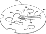
Fig. 4 is the vertical view of the substrate base of Fig. 1, and its demonstration is arranged on an embodiment of the cover plate on the base plate.
Fig. 5 is the vertical view of the substrate base of Fig. 1, has wherein removed cover plate to expose the top of base plate.
Fig. 6 is the upward view of the substrate base of Fig. 1.
Fig. 6 A-6B figure is partial cross section figure and the amplification inclinating view of an embodiment of guide of flow body.
Fig. 7 is the upward view of base plate.
Fig. 8 is the vertical view of an embodiment of raceway groove separating plate.
Fig. 9 is the upward view of raceway groove separating plate.
Figure 10 is the face upwarding stereogram of raceway groove separating plate.
Figure 11 is the partial cross section figure of the substrate base of Fig. 1.
Figure 12 is another part sectional view of the substrate base of Fig. 1, and it shows the connectivity port that is used for cooling entrance and outlet.
Figure 13 is the exploded perspective view of another embodiment of base portion assembly.
Figure 14-16 is upward view, end view and the vertical view of an embodiment of raceway groove separating plate of the base portion assembly of Figure 13.
Figure 17 is the face upwarding stereogram of an embodiment of entrance menifold cage.
Figure 18 is the part end view of raceway groove separating plate and entrance menifold cage.
Figure 19-21 is upward view, end view and the vertical view of an embodiment of bottom plate of the base portion assembly of Figure 13.
Figure 22 is the part sectional block diagram of the base portion assembly of Figure 13.
Figure 23-26 is the alternative upward view of base plate of the base portion assembly of Figure 13.
Embodiment
The present invention provides a kind of method and apparatus for control underlayer temperature during processing haply.Although the present invention is schematically with Semiconductor substrate treatment facility (CENTURA for example
 The processor of integrated semiconductor wafer processing system (or module), it can be obtained by the Applied Materials in santa clara city) describe, the present invention can be used in other treatment system (comprising etching, deposition, injection and heat treatment) or other wishes the application of control substrate or other workpiece temperature distribution (profile).
Fig. 1 illustrates the schematic diagram of an exemplary etch reactor 100, and it has the embodiment of substrate base assembly 116, and substrate base assembly 116 contains the inner radial coolant flow path.Specific etch reactor 100 embodiment in this demonstration are for the example purpose, and should not be used to limit the scope of the invention.
In illustrated embodiment, top, chamber 120 is electrolytic components of substantially flat.Other embodiment of process chamber 110 can have the top, chamber of other type, for example top, the chamber of domed shape.The chamber is pushed up 120 tops and is provided with antenna 112, and antenna 112 comprises or a plurality of conductive coil member (showing two coaxial coil members among the figure).Antenna 112 is couple to radio frequency (RF) plasma power source 118 via matching network 170.
In one embodiment, substrate base assembly 116 comprises installation component 162, base portion assembly 114 and electrostatic chuck 188.Installation component 162 is couple to process chamber 110 with base portion assembly 114.
Usually, electrostatic chuck 188 is to be formed by pottery or similar electrolyte, and comprises at least one holding electrode 186, and holding electrode 186 usefulness power supply units 128 are controlled.In further embodiment, electrostatic chuck 188 can comprise at least RF electrode (not shown), and the RF electrode is couple to the power source 122 with substrate bias via the second matching network 124.Electrostatic chuck 188 can optionally comprise one or more substrate heaters.In one embodiment, two with one heart and the resistance type heater (being shown as among the figure with center heater 184A, 184B) that can independently control edge to the central temperature that is used to control substrate 150 distribute.
Usually, base portion assembly 114 is to be formed by aluminium or other metal material.Base portion assembly 114 comprises one or more cooling ducts, and the cooling duct is couple to heating or cooling fluid source 182.Source 182 provides the temperature of heat transfer fluid (at least a gas (such as dichlorodifluoromethan, helium or nitrogen) etc. or liquid (such as water or oil) etc.) with control base portion assembly 114 via passage, heat by this or cooling base portion assembly 114, during processing, partly control by this temperature of the substrate 150 on the base portion assembly 114.
Fig. 2 A-2B is sectional view and the vertical view of an embodiment of substrate base assembly 116, shows the cooling flowing path 200 in order to the uniform temperature control that substrate base assembly 116 is provided among the figure.Substrate base assembly 116 comprises electrostatic chuck 188, and electrostatic chuck 188 is arranged on the base portion assembly 114.Stream 200 can be configured to by being formed on one or more passages of base portion assembly 114.Stream 200 has the haply radial orientation by base portion assembly 114.Thereby the heat transfer fluid that source 182 provides radially outwards flows although the stream 200 that Fig. 2 A shows has central inlet, and scrutable is that flow direction can be reversed.
In one embodiment, stream 200 comprises the first radial path 202 and the second radial path 204.First and 1 second radial path 202, the 204th, by construction with flowing in basic rightabout guiding heat transfer fluid.Haply, the diameter of base portion assembly 114 is greater than the diameter of electrostatic chuck 188, allowing the first and second radial path 202,204 radially extend beyond the external diameter of chuck 188 and substrate 150, and provides good temperature control at the edges of substrate place.
In the illustrated embodiment of Fig. 2 A-2B, the surface of the first radial path 202 adjacent base assemblies 114 contact electrostatic chucks 188, and the second radial path 204 is arranged on the first radial path 202 belows.In one embodiment, stream 200 has the mushroom geometric shape, for example is suspension column convex disks (torus).The tubular shape of stream 200 can be made of a plurality of other radial passages or single channel.
Tubular shape has reduced the flow path length that is used in the conventional sole significantly.For example, be applicable to process in the appropriate size base portion of 300mm substrate, the geometric shape of the stream of one embodiment of the present of invention with flow path length from the base portion of conventional substrate strutting piece about 72 inches reduce to about 6 inches.This length reduces the temperature drop between the entrance and exit that has reduced significantly the cooling duct, has reduced significantly by this temperature gradient in the substrate support pedestal.In one embodiment, the temperature difference between the entrance and exit of cooling duct (temperature delta) is about 0.1 to about 1.0 ℃, is about 7 to about 17 ℃ in the conventional substrate strutting piece.The fluid intake temperature range can be between-100 ℃ to approximately between+200 ℃, for example between-30 ℃ to about+85 ℃.Radially the arrangement of stream also can reduce flow resistance significantly, allows by this larger fluid flow and the rates of heat transfer of Geng Gao under selected operating pressure.
Fig. 3 is the sectional view of the base portion assembly 114 of Fig. 1.In an embodiment, base portion assembly 114 comprises internal coolant stream 300, and its orientation is substantially radially.In another embodiment, stream 300 can be constructed as stream 200 is described.
In one embodiment, base portion assembly 114 comprises lamina tecti 302, base plate 304, raceway groove separating plate 306 and bottom plate 308.Usually, plate 302,304,306, the 308th is made by good heat conductor, for example metal (such as stainless steel or aluminium).
Lamina tecti 302 is arranged in the recess 310, and recess 310 is formed in the top 312 of base plate 304.Can select the degree of depth of recess 310 to allow the top surface 328 of lamina tecti 302 and the top 312 basic coplines of base plate 304.Electrostatic chuck 188 (Fig. 3 is not shown) is supported on the top surface 328 of lamina tecti 302 at least.
With reference to the vertical view of the illustrated base portion assembly 114 of Fig. 4, lamina tecti 302 comprises a plurality of holes extraly.These holes are to pass through base portion assembly 114 to the configuration of electrostatic chuck 188 for the lifting tip and various heater, transducer, gas and power device.In the illustrated embodiment of Fig. 4, hole 314 is for the lifting tip, and hole 316 is used in the chuck power device, and hole 318 is for heater member, hole 320 is for temperature sensor, and hole 324, the 326th passes the conveying of gas for the heat between lamina tecti 302 and the electrostatic chuck 188.Identical element numbers can be used to indicate the hole that identical configuration is arranged in other parts of base portion assembly 114.
Fig. 5 is the vertical view of substrate base 114, has wherein removed the concave surface 340 of cover plate 302 to expose base plate 304.Concave surface 340 comprises a plurality of cooling groove channels that are formed on wherein.In the illustrated embodiment of Fig. 5, provide interior cooling groove channel 502 and outer cooling groove channel 504.Helium or other heat passes gas or fluid and is provided to cooling groove channel 502,504 via entrance 506,508 separately.Heat passes gas via raceway groove 502,504 distributed a plurality of holes 324,326 (being presented among Fig. 4) in cover plate 302, and heat passes gas and is distributed between electrostatic chuck 188 and the base portion assembly 114 by these holes 324,326.Can control independently the temperature of fluid in the raceway groove 502,504, to help to provide the underlayer temperature control at center to edge.
Refer again to Fig. 3, base plate 304 comprises chamber 334, and chamber 334 is formed in the bottom 336 of base plate 304.Bottom plate 308 is couple to the bottom 336 of base plate 304 hermetically, so that raceway groove separating plate 306 is sealed in the chamber 334.In one embodiment, bottom plate 308 is arranged on step 338 places, and wherein step 338 is formed in the bottom 336 of base plate 304, and bottom plate 308 is sealed to base plate 304 by continuous welding or other proper technology.
Raceway groove separating plate 306 is separated into chamber 334 pumping chamber 342,344 of two dishes.Pumping chamber 342,344 vertical stackings and via gap 346 fluids couple, its intermediate gap 346 is defined between the outer ledge of the lateral wall 348 of chamber 344 and raceway groove separating plate 306.In the illustrated embodiment of Fig. 3, radially coolant flow path be by from upper pumping chamber 342 by gap 348 to lower pumping chamber 344 interior defining.Also can understand, the direction that flows by stream can reverse.
In one embodiment, raceway groove separating plate 306 is kept the relation of separating by a plurality of septs 354 and the roof 352 of chamber 334.Sept 354 is the part of base plate 304.At least some septs 354 have radial orientation, to allow mobile being able to by upper pumping chamber 342 radially be guided.
Fig. 6 illustrates the upward view of base plate 304, and wherein these septs 354 are outstanding from roof 352.For clear, Fig. 6 only shows minority sept 354, but these septs 354 are with around 360 ° of center lines that are distributed in base plate 304.Gap between at least some sept 354 bridge joint roofs 352 and the raceway groove separating plate 306.Can select quantity, orientation, distribution and the size of these septs 354, pass distribution with the expectation heat that fluid from base plate 304 supreme pumping chambers 342 is provided.In the illustrated embodiment of Fig. 6, these septs 354 are long, and have the main shaft of aiming at radial flow direction.These septs 354 also can be interconnected, therefore there have flowing between two adjacent spaces things 354 of same radius to be directed toward by the center line in distance base plate 304 to be next to outer spacers 354, by this outwards 348 some transverse shiftings and the mixing that can cause cooling fluid when moving towards the gap at cooling fluid.
In addition, Fig. 6 shows a plurality of protruding 602, and various holes 314,316,318,320,322,324,326 extend through these projections 602.These projections 602 provide stopping between these holes and the pumping chamber 342.These projections 602 are aimed at a plurality of protruding 702 (being presented at Fig. 7), and wherein these projections 702 are positioned at the configuration of passing base assembly 116 with promotion device, transducer, heater, fluid etc. on the outside of bottom plate 308.Engaging and can weld or seal with another appropriate ways with ormolu between bottom plate 308 and the base plate 304 enters these holes to avoid fluid.
With reference to the local structure of Fig. 6 A-B, guide of flow body 604 can be arranged on the downstream of each projection 602 extraly, with the heat transfer fluid that promotes to flow through pumping chamber 342 can around throw one's back out side panel around.In one embodiment, the orientation of guide of flow body 604 is basically perpendicular to the orientation of these septs 354.Guide of flow body 604 can comprise one or more slits 606 extraly, the fluid that these slits 606 allow to be guided between projection 602 and the guide body 604 is flowed out, thereby keep flowing between projection 602 and the guide body 604, shown in the arrow of Fig. 6 B.Alternatively, guide of flow body 604 is the gap between the roof 352 of bridge joint raceway groove separating plate 306 and base plate 304 not, flows out to allow segment fluid flow between projection 602 and the guide body 604 can overflow across guide body 604 as the weir by this.The coiling of fluid impels the good heat from these projections 604 to pass, and has therefore compensated the low-heat biography speed by the hole in these holes.
Fig. 8 is the vertical view of the embodiment of raceway groove separating plate 306.Raceway groove separating plate 306 comprises a plurality of holes 802, and the projection 602 of base plate 304 extends through these holes 802.Raceway groove separating plate 306 also comprises one or more ingates 804, and these ingates 804 allow coolant fluid to enter chamber 334, and it will further describe hereinafter.
Fig. 9-10 is upward view and the face upwarding stereogram of raceway groove separating plate 306.Raceway groove separating plate 306 comprises that horizontal feedback part 908 is used for providing heat transfer fluid to arrive these ingates 804.Laterally feedback part 908 allows the center that the heat transfer fluid entrance of base assembly 116 departs from base, allows by this more effective space to use to dispose electric device, the lifting tip, gas raceway groove etc.In the illustrated embodiment of Fig. 9, laterally presenting part 908 is by defining from the outstanding wall 916 in the bottom of raceway groove separating plate 306.Wall 916 has the haply dog bone shape of hollow, couples pumping chamber 910,912 raceway groove its outer pumping chamber 910 round the first end place that is positioned at horizontal feedback part 908, the pumping chamber 912 at the second end place that is positioned at horizontal feedback part 908 and fluid.Haply, outer pumping chamber 910 outwards arranges from the center of raceway groove separating plate 306.(such as Fig. 3 and shown in Figure 12) aims at the fluid provider 398 in being formed on bottom plate 308 in outer pumping chamber 910.Haply, interior pumping chamber 912 is arranged on the center of raceway groove separating plate 306.Round the part of the wall 916 of interior pumping chamber 912 wide to enough with around these ingates 804, be defined in the central distribution pumping chamber on the side on the raceway groove separating plate 306 to allow fluid from horizontal feedback part 908 be conducted through these holes 804 in the raceway groove separating plate 306 and to enter.
Figure 11 is the enlarged side view of base portion assembly 114, an embodiment of its Graphic Center distribution pumping chamber 1102.Central distribution pumping chamber 1102 is subject to raceway groove separating plate 306 and is subject to base plate 304 at the top in the bottom.Wall 1106 extends downwards from base plate 304, so that the external boundary of central distribution pumping chamber 1102 to be provided.Wall 1106 is arranged on the outside in hole 804, provides the fluid passage to allow hole 804 between pumping chamber 912,1102.Wall 1106 is constructed as and allows fluid radially to flow to upper pumping chamber 342 from central distribution pumping chamber 1102, shown in arrow 1104.
In one embodiment, wall 1106 comprises one or more passages 1110 (for example hole or slit), and fluid can flow to upper pumping chamber 342 via these passages 1110 from central distribution pumping chamber 1102.In one embodiment, these passages 1110 are perforation.In the illustrated embodiment of Figure 11, wall 1106 has haply cylindrical shape, and passage 1110 is formed in the far-end.These passages 1110 can be at equidistant intervals along wall 1106.Alternatively, these passages 1110 can be constructed as and be continuous weir, and it allows all similarly being directed in the radial direction that be flowing in of fluid.Alternatively, can select quantity and the gap of these passages 1110, can guide when needed the zones that flow to upper pumping chamber 342, for another zone of upper pumping chamber 342 more.
As shown in figure 11, base plate 304 comprises central protuberance 1108, and central protuberance 1108 separates the fluid in central passage 1112 and the pumping chamber 912,1102.Central passage 1112 is in alignment with the hole 316 of passing lamina tecti 302 formation and pass the hole 1118 that bottom plate 308 forms.Passage 1112, hole 316 have promoted device to pass base assembly 116 to the configuration of electrostatic chuck 118 with hole 1118.Engage and to weld or to seal with another appropriate ways with ormolu between the bottom plate 308 and protruding 1108, enter these passages to avoid fluid.Bottom plate 308 a plurality of protruding 702 in one (in Figure 11, be shown as projection 1114) have the port that is formed on wherein to promote coupling of device conduit.Other projection 702 is come construction similarly.
The fluid issuing of the stream by base assembly 116 is shown among the partial cross section figure of Figure 12.Fluid issuing hole 1202 is passed bottom plate 308 and is formed, to discharge (drain) lower pumping chamber 344.Haply, outlet opening 1202 is near ingate 398.Two projections 702 (be shown as entrance projection 1204 and be connected projection 1206 in Figure 12) that are formed on the bottom plate 308 are used for providing the fluid of flow path 300 to connect via hole 398,1202.In one embodiment, projection 1204 is couple to heat transfer fluid source 182, and projection 1206 is couple to outlet or recycled back fluid source 182.The heat that pressure, flow velocity, temperature, density and the composition of the hot medium matter of the cooling fluid by stream 300 strengthened by base assembly 116 passes the control that distributes.Moreover during substrate 150 was processed, because density, pressure and the flow velocity of the fluid in the stream 300 can original position (in-situ) be controlled, therefore the control of the temperature of substrate 150 can change with the progressive treatment efficiency that promotes during processing.
When operation, provide substrate 150 to base assembly 116.Provide power to electrostatic chuck 188, to fix substrate.Power is provided to the heater in the electrostatic chuck 188, with the transverse temperature distribution of control substrate 150.Coolant fluid (it can be fluid and gas (such as dichlorodifluoromethan)) provides via the radially cooling path that is defined in the base portion assembly 114, can accurately control underlayer temperature.
In one embodiment, cooling agent is provided to central distribution pumping chamber 1102, and cooling agent radially is distributed in the upper pumping chamber 342 of dish from central distribution pumping chamber 1102 via these passages 1110.Guide of flow body 604 be used for promoting the flowing through heat transfer fluid of upper pumping chamber 342 extends through the coiling of the projection 604 of pumping chamber 342 around each.Then, cooling agent flow to lower dish-shaped pumping chamber 344 via gap 348 from upper pumping chamber 342, and cooling agent removes from lower dish-shaped pumping chamber 344 at last.Radially configuration and the flow orientation of coolant flow path have reduced coolant line electrical path length and pressure drop, have advantageously increased the cooling uniformity of base assembly 116, have improved by this processing controls in the reactor 100.
For example, above-mentioned underlayer temperature control can advantageously (multiple gases that wherein provides from gas panels 138 forms plasma in reactor 100) use in etch processes.Other substrate manufacture process, for example above-mentioned and carry out in vacuum chamber and the substrate manufacture process that needs accurate temperature to control, also can be benefited from the use of temperature-controlled process described here and equipment.
Figure 13 is the exploded perspective view of another embodiment of base portion assembly 1300, and heat transfer fluid flow to lower dish-shaped pumping chamber from upper dish-shaped pumping chamber and passes through this base portion assembly 300, and wherein fluid is removed from lower dish-shaped pumping chamber at last.Base portion assembly 1300 comprises base plate 1302, raceway groove separating plate 1304 and bottom plate 1306.Base plate 1302 is coupled in hermetically with bottom plate 1306, raceway groove separating plate 1304 is positioned between the two, allowing the external diameter 1314 that is incorporated into that coolant fluid between raceway groove separating plate and the base plate can outwards flow and surpasses raceway groove separating plate 1304, and enter in the pumping chamber, the end that is defined between raceway groove separating plate 1304 and the bottom plate 1306.Base plate 1302, raceway groove separating plate 1304 and bottom plate 1306 all comprise centre bore 1308, centre bore 1308 is provided for disposing power supply and other installs to electrostatic chuck 188 conduit of (showing in Fig. 1), and wherein this electrostatic chuck 188 is couple to the top 1316 of base plate 1302.
The top 1316 of base plate 1302 comprises interior raceway groove 1318 and outer cooling groove channel 1320 extraly.Interior raceway groove 1318 is to come the feed-in fluid via the entrance 1322 that is formed on base plate 1302.Outer raceway groove 1320 is to come the feed-in fluid via the entrance 1324 that is formed on base plate 1302.Cooling groove channel feed-in mouth 1328,1330 is arranged in the bottom plate 1306 and in alignment with entrance 1320,1322, to allow fluid (for example He, nitrogen or other fluid) to flow to cooling groove channel 1318,1320 via base assembly, pass with the heat that increases between assembly 1300 and the electrostatic chuck 118.Hole 1326 is arranged in the raceway groove separating plate 1304, to promote cooling groove channel feed-in mouth 1328,1330 and entrance 1322,1324 couple.
Figure 14-16 is upward view, vertical view and the end view of raceway groove separating plate 1304.Raceway groove separating plate 1304 comprises bottom 1402 and top 1602.The first projection 1,404 1402 is extended from the bottom, thereby forms a recess in the top 1602 of raceway groove separating plate 1304.Be formed on the part that recess in the first projection 1404 holds entrance menifold cage 1502, wherein this entrance menifold cage 1502 extends from the top 1602 of raceway groove separating plate 1304.The second projection 1406 is extended from the first projection 1404 from the bottom 1402 of raceway groove separating plate 1304.The second projection 1406 comprises passes the passage 1408 that raceway groove separating plate 1304 forms.Passage 1408 allows fluid to enter base portion assembly 1300, and flows through entrance menifold cage 1502 and enter the upper pumping chamber that is defined between raceway groove separating plate 1304 and the base plate 1302.
Figure 17 is the face upwarding stereogram of the embodiment of entrance menifold cage 1502.Entrance menifold cage 1502 comprises annular inner wall 1702, and side 1504 is around this annular inner wall 1702.The inwall 1702 of entrance menifold cage 1502, side 1504 have defined fluid passage 1704 with top 1506 in entrance menifold cage 1502.
Figure 18 is the part end view of raceway groove separating plate 1304 and entrance menifold cage 1502.Shown in Figure 18 illustrated embodiment, entrance menifold cage 1502 partly is located in the recess that is formed in the projection 1404.These windows 1508 are arranged near top 1506 along a side 1504 of entrance menifold cage 1502, thereby so that these windows 1508 are configured to be provided fluid to the top 1602 of raceway groove separating plate 1304.Therefore, via pass projection 1406 passages that define 1408 enter the fluid of fluid passage 1704 can be easily to flow to upper pumping chamber from side 1504 radially outer directions.
Figure 19-21 is upward view, end view and the vertical view of an embodiment of bottom plate 1306.The bottom 1902 of bottom plate 1306 comprises a plurality of wherein chambers 1904 of being formed on to reduce the thermal mass (thermal mass) of bottom plate 1306, allows by this assembly 1300 to be heated more quickly and cools off.Bottom plate 1306 comprises that extraly two are passed wherein the hole 1906,1908 that forms, and hole 1906,1908 can promote to pass in and out the configuration of the cooling fluid of base portion assembly 1300.Hole 1906 is even as big as holding from raceway groove separating plate 1304 extended protruding 1406.Hole 1908 can promote to be defined in the discharge (drain) of the lower pumping chamber between bottom plate 1306 and the raceway groove separating plate 1304.Hole 1908 can be in the bottom 1902 comprises subtend hole 2102, to promote and the aiming at of component.
The top 2002 of bottom plate 1306 comprises the first projection the 2004 and second projection 2006.The first projection 2004 is around centre bore 1308.The second projection 2006 has passes the passage 1332 that wherein forms, and it is used for temperature sensing.Bottom plate 1306 also can comprise the second hole 1910, is used for holding the temperature probe of the temperature that is suitable for sensing bottom plate 1306.
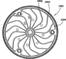
Figure 22 is the part sectional block diagram of base portion assembly 1300.In Figure 22 illustrated embodiment, base plate 1302 comprises edge 2250, and edge 2250 extends from the bottom side of base plate 1302.Edge 2250 has madial wall 2254, and madial wall 2254 defines bag 2256, and raceway groove separating plate 1304 and bottom plate 1306 are accommodated in the bag 2256.The edge 2250 of bottom plate 1306 by for example continuous welding, be sealed to base plate 1302 with ormolu welding or other proper technology, to keep somewhere the fluid that flows through upper pumping chamber and lower pumping chamber in the assembly 1300.Bag 2256 has bottom 2258, and raceway groove separating plate 1304 is arranged on this bottom 2258.Bottom 2258 comprises a plurality of fins 2206 extraly, and these fins 2206 separate a plurality of raceway grooves 2208 that are formed in the bottom 2258.Hereinafter with reference to Figure 23-26 fin 2206 and raceway groove 2208 are described in more detail.Raceway groove 2208 has defined the major part of the upper pumping chamber 2220 between the bottom 2258 that is defined in raceway groove separating plate 1304 and base plate 1302.Fluid enters upper pumping chamber 2220 via the window 1508 that is formed in the entrance menifold cage 1502.Fluid is from entrance menifold cage 1502 via the raceway groove 2208 of upper pumping chamber 2220 and flow into around edge 1314 in the ditch 2114 between the madial wall 2254 of the edge 1314 that is defined in raceway groove separating plate 1304 and base plate 1302.Fluid flows to lower pumping chamber 2222 and flows out from ditch 2114 and passes the hole 1908 that bottom plate 1308 forms.Therefore, be similar to the base portion assembly 114 that 2A-2B figure describes by the pumping chamber 2220 of base portion assembly 1300,2222 nowed forming.
Figure 23-26 is the alternative upward view of the base plate 1302 of base portion assembly 1300.The common trait of the embodiment of Figure 23-26 is: the basic radial orientation of raceway groove 2208 and by pumping chamber 2220,2222 relative radial flow direction.
A plurality of pads 2210 extend from the basal surface of base plate 1302.In an embodiment, show among the figure that seven pads extend in fin 2206 tops.Pad 2210 separates raceway groove separating plate 1304 and base plate 1302, sets up by this little gap between raceway groove separating plate 1304 and these fins 2206, thereby so that has minimum heat biography between base plate 1302 and raceway groove separating plate 1304.
In the illustrated embodiment of Figure 23, these raceway grooves 2208 outwards have basic uniformly width and sectional area across the bottom of base plate 1302 along its radical length.For this basic uniformly channel width is provided, these fins 2206 are horn-like expansion, when fin becomes wider during near the outer ledge of base plate 1302 gradually.These raceway grooves 2208 can be linear, crooked, that radially bend or have other orientation.In the illustrated embodiment of Figure 23, these raceway grooves 2208 are crooked, to allow the fluid that flows through these raceway grooves 2208 have the longer residence time in upper pumping chamber 2220, increase by this hot transfer efficiency.
In the illustrated embodiment of Figure 24, these raceway grooves 2208 comprise tap drain road 2402 and a plurality of sub-channel 2404 from tap drain road branch.In the illustrated embodiment of Figure 24, show at least two sub-channel among the figure.Yet tap drain road 2402 can have three sub-channel 2404 of surpassing, and these sub-channel itself can be branched off into two or more times raceway groove (not shown).These sub-channel are to separate by the fin 2406 between raceway groove.
In the illustrated embodiment of Figure 25, show among the figure that a plurality of raceway grooves 2502 are to separate by a plurality of fins 2504.These raceway grooves 2502 can have uniform sectional area and width when extending radially outwardly along with raceway groove 2502.Alternatively, the sectional area of these raceway grooves 2502 and width can be along with raceway groove 2502 be horn-like expansion during near the external diameter of base plate 1302.In the illustrated embodiment of Figure 25, these fins 2504 of separating these raceway grooves 2502 have basic boomerang (boomerang) shape, and the center of fin 2504 is thicker with respect to each end.This boomerang shape allows dark crooked raceway groove 2502, substantially increases by this residence time of fluid in upper pumping chamber 2220.
In body 26 illustrated embodiment, show among the figure that a plurality of raceway grooves 2602 are to separate by a plurality of fins 2604.Each fin 2604 has basic uniformly sectional area and width when extending radially outwardly along with fin 2604.Correspondingly, these raceway grooves 2602 are along with it outwards is horn-like expansion when the edge of base plate 1302 moves.These fins 2604 can extend linearly in radial direction, or can be crooked with the residence time in the raceway groove 2602 that increases cooling fluid pumping chamber 2220 on defining.
Therefore, the present invention provides a kind of base assembly, and it comprises radially coolant flow path.This radially coolant flow path by base assembly provides the temperature control of improvement, is controlled by this substrate temperature and distributes.
Although above stated specification focuses on embodiments of the invention, do not breaking away under the base region of the present invention, can envision of the present invention other with further embodiment, and scope of the present invention is to be decided by the claim of enclosing.
Claims (20)
1. method that is used for control underlayer temperature during processing, described method comprises:
Substrate is positioned on the substrate base assembly in the vacuum processing chamber;
By making heat transfer fluid flow through the temperature that single radially stream in the described substrate base assembly is controlled described substrate base assembly, described single radially stream comprises the first dish-shaped pumping chamber, the second dish-shaped pumping chamber and radially inwardly part and part radially outward, described radially outward part is limited by the described first dish-shaped pumping chamber, and described radially inside part is limited by the described second dish-shaped pumping chamber; And
Plasma treatment is positioned at the described substrate on the described substrate base assembly that is subjected to temperature control.
2. the method for claim 1, wherein said plasma treatment is at least one of chemical vapor deposition method, physical gas-phase deposition, ion implantation technology or etch process.
3. the method for claim 1, wherein said control comprises:
Make described heat transfer fluid flow through the stream of basic ring-type.
4. the method for claim 1 also comprises:
Guide described heat transfer fluid flowing in described stream at the obstacle rear.
5. the method for claim 1, wherein said control comprises:
Make described heat transfer fluid flow to the center of described substrate base assembly; And
Described heat transfer fluid is radially outwards flowed from the center of described substrate base assembly.
6. method as claimed in claim 5, wherein said flowing comprises:
Make described heat transfer fluid flow through the annular gap and enter the described second dish-shaped pumping chamber, wherein said annular gap is defined in the described first dish-shaped pumping chamber and radially outward locates.
7. base assembly comprises:
Electrostatic chuck; And
The base portion assembly, described electrostatic chuck is fixed to the top of described base portion assembly, described base portion assembly has the single cooling flowing path that is formed in the described base portion assembly, described single cooling flowing path is used for the guiding heat transfer fluid and passes through radially stream, described radially stream comprises the first dish-shaped pumping chamber, the second dish-shaped pumping chamber and radially inwardly part and radially outward part, described radially inside part is limited by the described first dish-shaped pumping chamber, and described radially outward part is limited by the described second dish-shaped pumping chamber.
8. base assembly as claimed in claim 7, wherein said base portion assembly comprises:
Base plate, described electrostatic chuck is fixed to described base plate; And
Bottom plate, it is couple to the bottom of described base plate hermetically, and wherein said single cooling flowing path is defined between described base plate and the described bottom plate and comprises the described first dish-shaped pumping chamber.
9. base assembly as claimed in claim 7, wherein said base portion assembly comprises:
Base plate, described electrostatic chuck is fixed to described base plate;
Bottom plate, it is couple to the bottom of described base plate hermetically; And
The raceway groove separating plate, it is arranged between described base plate and the described bottom plate, and wherein said single cooling flowing path is at least part of to be defined between described raceway groove separating plate and the described base plate and at least part of being defined between described raceway groove separating plate and the described bottom plate.
10. base assembly as claimed in claim 9, wherein said base plate comprises:
A plurality of fins, it extends in the described stream and has substantially radially orientation.
11. base assembly as claimed in claim 10, wherein at least one described fin has linear orientation.
12. base assembly as claimed in claim 10, wherein at least one described fin is crooked.
13. base assembly as claimed in claim 10 is formed on wherein that at least one is branched off at least two sub-channel in the described raceway groove between two described fins.
14. base assembly as claimed in claim 9 also comprises:
Entrance menifold cage, it is couple to described raceway groove separating plate, and described entrance menifold cage has a plurality of windows, is used for allowing fluid outwards to flow through described entrance menifold cage.
15. base assembly as claimed in claim 9, wherein,
The second dish-shaped pumping chamber is defined between described raceway groove separating plate and the described base plate; And
The first dish-shaped pumping chamber is defined between described raceway groove separating plate and the described bottom plate.
16. a base assembly comprises:
Electrostatic chuck;
The base portion assembly, described electrostatic chuck is fixed to the top of described base portion assembly;
The stream of single basic ring-type, it is formed in the described base portion assembly, and the stream of described single basic ring-type has:
Be formed on entrance and the outlet of the basal surface of described base portion assembly;
The the first dish-shaped pumping chamber that is communicated with described inlet fluid; With
The the second dish-shaped pumping chamber that is communicated with described outlet fluid, wherein, the stream of described single basic ring-type comprises radially inwardly part and radially outward part, and described radially outward part is limited by the described first dish-shaped pumping chamber, and described radially inside part is limited by the described second dish-shaped pumping chamber.
17. base assembly as claimed in claim 16, wherein said base portion assembly comprises:
Base plate, described electrostatic chuck is fixed to described base plate;
The raceway groove separating plate, it arranges with the relation that separates with respect to described base plate by a plurality of pads, and the stream of described single basic ring-type extends in the outer rim top of described raceway groove separating plate;
Bottom plate, it is to be couple to hermetically the bottom of described base plate with respect to the relation that separates of described raceway groove separating plate.
18. base assembly as claimed in claim 17, wherein said bottom plate comprises:
The first hole, it is open into the space that is defined between described bottom plate and the described raceway groove separating plate; And
The second hole, it is couple to the space that is defined between described base plate and the described raceway groove separating plate.
19. base assembly as claimed in claim 17, wherein said base plate comprises:
A plurality of fins, it extends in the described stream and has substantially radially orientation.
20. base assembly as claimed in claim 17, wherein said base portion assembly comprises:
The fin of a plurality of bendings, it extends in the stream of described single basic ring-type and has substantially radially orientation.
Applications Claiming Priority (3)
| Application Number | Priority Date | Filing Date | Title |
|---|---|---|---|
| US1600007P | 2007-12-21 | 2007-12-21 | |
| US61/016,000 | 2007-12-21 | ||
| PCT/US2008/087533 WO2009086013A2 (en) | 2007-12-21 | 2008-12-18 | Method and apparatus for controlling temperature of a substrate |
Publications (2)
| Publication Number | Publication Date |
|---|---|
| CN101903996A CN101903996A (en) | 2010-12-01 |
| CN101903996B true CN101903996B (en) | 2013-04-03 |
Family
ID=40787366
Family Applications (1)
| Application Number | Title | Priority Date | Filing Date |
|---|---|---|---|
| CN2008801222384A Expired - Fee Related CN101903996B (en) | 2007-12-21 | 2008-12-18 | Method and apparatus for controlling temperature of a substrate |
Country Status (6)
| Country | Link |
|---|---|
| US (1) | US20090159566A1 (en) |
| JP (1) | JP2011508436A (en) |
| KR (1) | KR20100103627A (en) |
| CN (1) | CN101903996B (en) |
| TW (1) | TW200937563A (en) |
| WO (1) | WO2009086013A2 (en) |
Families Citing this family (121)
| Publication number | Priority date | Publication date | Assignee | Title |
|---|---|---|---|---|
| US20060105182A1 (en) * | 2004-11-16 | 2006-05-18 | Applied Materials, Inc. | Erosion resistant textured chamber surface |
| US7221553B2 (en) * | 2003-04-22 | 2007-05-22 | Applied Materials, Inc. | Substrate support having heat transfer system |
| WO2011056433A2 (en) * | 2009-11-03 | 2011-05-12 | Applied Materials, Inc. | Temperature control of a substrate during a plasma ion implantation process for patterned disc media applications |
| JP2011184738A (en) * | 2010-03-09 | 2011-09-22 | Fujifilm Corp | Method for producing gas barrier film |
| US8772103B2 (en) * | 2010-10-25 | 2014-07-08 | Texas Instruments Incorporated | Low temperature implant scheme to improve BJT current gain |
| US9719169B2 (en) * | 2010-12-20 | 2017-08-01 | Novellus Systems, Inc. | System and apparatus for flowable deposition in semiconductor fabrication |
| US10283321B2 (en) | 2011-01-18 | 2019-05-07 | Applied Materials, Inc. | Semiconductor processing system and methods using capacitively coupled plasma |
| US9245717B2 (en) | 2011-05-31 | 2016-01-26 | Lam Research Corporation | Gas distribution system for ceramic showerhead of plasma etch reactor |
| US8562785B2 (en) * | 2011-05-31 | 2013-10-22 | Lam Research Corporation | Gas distribution showerhead for inductively coupled plasma etch reactor |
| WO2013033348A1 (en) * | 2011-08-30 | 2013-03-07 | Watlow Electric Manufacturing Company | System and method for controlling a thermal array |
| US20130276980A1 (en) * | 2012-04-23 | 2013-10-24 | Dmitry Lubomirsky | Esc with cooling base |
| US10537013B2 (en) * | 2012-04-23 | 2020-01-14 | Applied Materials, Inc. | Distributed electro-static chuck cooling |
| US9267739B2 (en) * | 2012-07-18 | 2016-02-23 | Applied Materials, Inc. | Pedestal with multi-zone temperature control and multiple purge capabilities |
| US9373517B2 (en) | 2012-08-02 | 2016-06-21 | Applied Materials, Inc. | Semiconductor processing with DC assisted RF power for improved control |
| US9132436B2 (en) | 2012-09-21 | 2015-09-15 | Applied Materials, Inc. | Chemical control features in wafer process equipment |
| WO2014116392A1 (en) * | 2013-01-25 | 2014-07-31 | Applied Materials, Inc. | Electrostatic chuck with concentric cooling base |
| US10256079B2 (en) | 2013-02-08 | 2019-04-09 | Applied Materials, Inc. | Semiconductor processing systems having multiple plasma configurations |
| US9362130B2 (en) | 2013-03-01 | 2016-06-07 | Applied Materials, Inc. | Enhanced etching processes using remote plasma sources |
| US9847222B2 (en) | 2013-10-25 | 2017-12-19 | Lam Research Corporation | Treatment for flowable dielectric deposition on substrate surfaces |
| US10217615B2 (en) | 2013-12-16 | 2019-02-26 | Lam Research Corporation | Plasma processing apparatus and component thereof including an optical fiber for determining a temperature thereof |
| US9847240B2 (en) * | 2014-02-12 | 2017-12-19 | Axcelis Technologies, Inc. | Constant mass flow multi-level coolant path electrostatic chuck |
| US9309598B2 (en) | 2014-05-28 | 2016-04-12 | Applied Materials, Inc. | Oxide and metal removal |
| US10249511B2 (en) * | 2014-06-27 | 2019-04-02 | Lam Research Corporation | Ceramic showerhead including central gas injector for tunable convective-diffusive gas flow in semiconductor substrate processing apparatus |
| US9986598B2 (en) * | 2014-07-02 | 2018-05-29 | Applied Materials, Inc. | Temperature control apparatus including groove-routed optical fiber heating, substrate temperature control systems, electronic device processing systems, and processing methods |
| KR101545119B1 (en) * | 2014-08-14 | 2015-08-18 | (주)얼라이드 테크 파인더즈 | Plasma device |
| US10049921B2 (en) | 2014-08-20 | 2018-08-14 | Lam Research Corporation | Method for selectively sealing ultra low-k porous dielectric layer using flowable dielectric film formed from vapor phase dielectric precursor |
| US9753463B2 (en) * | 2014-09-12 | 2017-09-05 | Applied Materials, Inc. | Increasing the gas efficiency for an electrostatic chuck |
| US9966240B2 (en) | 2014-10-14 | 2018-05-08 | Applied Materials, Inc. | Systems and methods for internal surface conditioning assessment in plasma processing equipment |
| US9355922B2 (en) | 2014-10-14 | 2016-05-31 | Applied Materials, Inc. | Systems and methods for internal surface conditioning in plasma processing equipment |
| US11637002B2 (en) | 2014-11-26 | 2023-04-25 | Applied Materials, Inc. | Methods and systems to enhance process uniformity |
| US10573496B2 (en) | 2014-12-09 | 2020-02-25 | Applied Materials, Inc. | Direct outlet toroidal plasma source |
| US10224210B2 (en) | 2014-12-09 | 2019-03-05 | Applied Materials, Inc. | Plasma processing system with direct outlet toroidal plasma source |
| US11257693B2 (en) | 2015-01-09 | 2022-02-22 | Applied Materials, Inc. | Methods and systems to improve pedestal temperature control |
| US9728437B2 (en) | 2015-02-03 | 2017-08-08 | Applied Materials, Inc. | High temperature chuck for plasma processing systems |
| US20160225652A1 (en) | 2015-02-03 | 2016-08-04 | Applied Materials, Inc. | Low temperature chuck for plasma processing systems |
| US10497606B2 (en) * | 2015-02-09 | 2019-12-03 | Applied Materials, Inc. | Dual-zone heater for plasma processing |
| US9691645B2 (en) | 2015-08-06 | 2017-06-27 | Applied Materials, Inc. | Bolted wafer chuck thermal management systems and methods for wafer processing systems |
| US9741593B2 (en) | 2015-08-06 | 2017-08-22 | Applied Materials, Inc. | Thermal management systems and methods for wafer processing systems |
| US9349605B1 (en) | 2015-08-07 | 2016-05-24 | Applied Materials, Inc. | Oxide etch selectivity systems and methods |
| US10504700B2 (en) | 2015-08-27 | 2019-12-10 | Applied Materials, Inc. | Plasma etching systems and methods with secondary plasma injection |
| US10586718B2 (en) * | 2015-11-11 | 2020-03-10 | Applied Materials, Inc. | Cooling base with spiral channels for ESC |
| US10388546B2 (en) | 2015-11-16 | 2019-08-20 | Lam Research Corporation | Apparatus for UV flowable dielectric |
| US9916977B2 (en) | 2015-11-16 | 2018-03-13 | Lam Research Corporation | Low k dielectric deposition via UV driven photopolymerization |
| JP6530701B2 (en) * | 2015-12-01 | 2019-06-12 | 日本特殊陶業株式会社 | Electrostatic chuck |
| US10780447B2 (en) * | 2016-04-26 | 2020-09-22 | Applied Materials, Inc. | Apparatus for controlling temperature uniformity of a showerhead |
| US10522371B2 (en) | 2016-05-19 | 2019-12-31 | Applied Materials, Inc. | Systems and methods for improved semiconductor etching and component protection |
| US10504754B2 (en) | 2016-05-19 | 2019-12-10 | Applied Materials, Inc. | Systems and methods for improved semiconductor etching and component protection |
| KR102490594B1 (en) * | 2016-07-18 | 2023-01-19 | 세메스 주식회사 | Chuck of supporting substrate and probe station having the same |
| WO2018016384A1 (en) * | 2016-07-19 | 2018-01-25 | 日本碍子株式会社 | Electrostatic chuck heater |
| US10062575B2 (en) | 2016-09-09 | 2018-08-28 | Applied Materials, Inc. | Poly directional etch by oxidation |
| US10629473B2 (en) | 2016-09-09 | 2020-04-21 | Applied Materials, Inc. | Footing removal for nitride spacer |
| US10546729B2 (en) | 2016-10-04 | 2020-01-28 | Applied Materials, Inc. | Dual-channel showerhead with improved profile |
| US9934942B1 (en) | 2016-10-04 | 2018-04-03 | Applied Materials, Inc. | Chamber with flow-through source |
| US10062585B2 (en) | 2016-10-04 | 2018-08-28 | Applied Materials, Inc. | Oxygen compatible plasma source |
| US10062579B2 (en) | 2016-10-07 | 2018-08-28 | Applied Materials, Inc. | Selective SiN lateral recess |
| US9947549B1 (en) | 2016-10-10 | 2018-04-17 | Applied Materials, Inc. | Cobalt-containing material removal |
| US9768034B1 (en) | 2016-11-11 | 2017-09-19 | Applied Materials, Inc. | Removal methods for high aspect ratio structures |
| US10163696B2 (en) | 2016-11-11 | 2018-12-25 | Applied Materials, Inc. | Selective cobalt removal for bottom up gapfill |
| US10026621B2 (en) | 2016-11-14 | 2018-07-17 | Applied Materials, Inc. | SiN spacer profile patterning |
| US10242908B2 (en) | 2016-11-14 | 2019-03-26 | Applied Materials, Inc. | Airgap formation with damage-free copper |
| KR101750409B1 (en) * | 2016-11-17 | 2017-06-23 | (주)디이에스 | Cooling chuck of a semiconductor wafer |
| US10566206B2 (en) | 2016-12-27 | 2020-02-18 | Applied Materials, Inc. | Systems and methods for anisotropic material breakthrough |
| US10403507B2 (en) | 2017-02-03 | 2019-09-03 | Applied Materials, Inc. | Shaped etch profile with oxidation |
| US10431429B2 (en) | 2017-02-03 | 2019-10-01 | Applied Materials, Inc. | Systems and methods for radial and azimuthal control of plasma uniformity |
| US10043684B1 (en) | 2017-02-06 | 2018-08-07 | Applied Materials, Inc. | Self-limiting atomic thermal etching systems and methods |
| US10319739B2 (en) | 2017-02-08 | 2019-06-11 | Applied Materials, Inc. | Accommodating imperfectly aligned memory holes |
| US10559451B2 (en) * | 2017-02-15 | 2020-02-11 | Applied Materials, Inc. | Apparatus with concentric pumping for multiple pressure regimes |
| US10943834B2 (en) | 2017-03-13 | 2021-03-09 | Applied Materials, Inc. | Replacement contact process |
| US10319649B2 (en) | 2017-04-11 | 2019-06-11 | Applied Materials, Inc. | Optical emission spectroscopy (OES) for remote plasma monitoring |
| US11011355B2 (en) * | 2017-05-12 | 2021-05-18 | Lam Research Corporation | Temperature-tuned substrate support for substrate processing systems |
| US11276590B2 (en) | 2017-05-17 | 2022-03-15 | Applied Materials, Inc. | Multi-zone semiconductor substrate supports |
| US11276559B2 (en) | 2017-05-17 | 2022-03-15 | Applied Materials, Inc. | Semiconductor processing chamber for multiple precursor flow |
| US10049891B1 (en) | 2017-05-31 | 2018-08-14 | Applied Materials, Inc. | Selective in situ cobalt residue removal |
| US10497579B2 (en) | 2017-05-31 | 2019-12-03 | Applied Materials, Inc. | Water-free etching methods |
| US10920320B2 (en) | 2017-06-16 | 2021-02-16 | Applied Materials, Inc. | Plasma health determination in semiconductor substrate processing reactors |
| US10541246B2 (en) | 2017-06-26 | 2020-01-21 | Applied Materials, Inc. | 3D flash memory cells which discourage cross-cell electrical tunneling |
| US10727080B2 (en) | 2017-07-07 | 2020-07-28 | Applied Materials, Inc. | Tantalum-containing material removal |
| US10541184B2 (en) | 2017-07-11 | 2020-01-21 | Applied Materials, Inc. | Optical emission spectroscopic techniques for monitoring etching |
| US10354889B2 (en) | 2017-07-17 | 2019-07-16 | Applied Materials, Inc. | Non-halogen etching of silicon-containing materials |
| US10170336B1 (en) | 2017-08-04 | 2019-01-01 | Applied Materials, Inc. | Methods for anisotropic control of selective silicon removal |
| US10043674B1 (en) | 2017-08-04 | 2018-08-07 | Applied Materials, Inc. | Germanium etching systems and methods |
| US10297458B2 (en) | 2017-08-07 | 2019-05-21 | Applied Materials, Inc. | Process window widening using coated parts in plasma etch processes |
| US10283324B1 (en) | 2017-10-24 | 2019-05-07 | Applied Materials, Inc. | Oxygen treatment for nitride etching |
| US10424487B2 (en) | 2017-10-24 | 2019-09-24 | Applied Materials, Inc. | Atomic layer etching processes |
| US10128086B1 (en) | 2017-10-24 | 2018-11-13 | Applied Materials, Inc. | Silicon pretreatment for nitride removal |
| US11236422B2 (en) * | 2017-11-17 | 2022-02-01 | Lam Research Corporation | Multi zone substrate support for ALD film property correction and tunability |
| US10256112B1 (en) | 2017-12-08 | 2019-04-09 | Applied Materials, Inc. | Selective tungsten removal |
| US10903054B2 (en) | 2017-12-19 | 2021-01-26 | Applied Materials, Inc. | Multi-zone gas distribution systems and methods |
| US11328909B2 (en) | 2017-12-22 | 2022-05-10 | Applied Materials, Inc. | Chamber conditioning and removal processes |
| US10854426B2 (en) | 2018-01-08 | 2020-12-01 | Applied Materials, Inc. | Metal recess for semiconductor structures |
| US10679870B2 (en) | 2018-02-15 | 2020-06-09 | Applied Materials, Inc. | Semiconductor processing chamber multistage mixing apparatus |
| US10964512B2 (en) | 2018-02-15 | 2021-03-30 | Applied Materials, Inc. | Semiconductor processing chamber multistage mixing apparatus and methods |
| TWI766433B (en) | 2018-02-28 | 2022-06-01 | 美商應用材料股份有限公司 | Systems and methods to form airgaps |
| US10593560B2 (en) | 2018-03-01 | 2020-03-17 | Applied Materials, Inc. | Magnetic induction plasma source for semiconductor processes and equipment |
| US10319600B1 (en) | 2018-03-12 | 2019-06-11 | Applied Materials, Inc. | Thermal silicon etch |
| US10497573B2 (en) | 2018-03-13 | 2019-12-03 | Applied Materials, Inc. | Selective atomic layer etching of semiconductor materials |
| US10573527B2 (en) | 2018-04-06 | 2020-02-25 | Applied Materials, Inc. | Gas-phase selective etching systems and methods |
| US10490406B2 (en) | 2018-04-10 | 2019-11-26 | Appled Materials, Inc. | Systems and methods for material breakthrough |
| US10699879B2 (en) | 2018-04-17 | 2020-06-30 | Applied Materials, Inc. | Two piece electrode assembly with gap for plasma control |
| US10886137B2 (en) | 2018-04-30 | 2021-01-05 | Applied Materials, Inc. | Selective nitride removal |
| JP2019201086A (en) * | 2018-05-15 | 2019-11-21 | 東京エレクトロン株式会社 | Processing device, component, and temperature control method |
| JP7456951B2 (en) | 2018-07-05 | 2024-03-27 | ラム リサーチ コーポレーション | Dynamic temperature control of substrate supports in substrate processing systems |
| US10872778B2 (en) | 2018-07-06 | 2020-12-22 | Applied Materials, Inc. | Systems and methods utilizing solid-phase etchants |
| US10755941B2 (en) | 2018-07-06 | 2020-08-25 | Applied Materials, Inc. | Self-limiting selective etching systems and methods |
| US10672642B2 (en) | 2018-07-24 | 2020-06-02 | Applied Materials, Inc. | Systems and methods for pedestal configuration |
| US10892198B2 (en) | 2018-09-14 | 2021-01-12 | Applied Materials, Inc. | Systems and methods for improved performance in semiconductor processing |
| US11049755B2 (en) | 2018-09-14 | 2021-06-29 | Applied Materials, Inc. | Semiconductor substrate supports with embedded RF shield |
| US11062887B2 (en) | 2018-09-17 | 2021-07-13 | Applied Materials, Inc. | High temperature RF heater pedestals |
| US11417534B2 (en) | 2018-09-21 | 2022-08-16 | Applied Materials, Inc. | Selective material removal |
| US11217433B2 (en) * | 2018-10-05 | 2022-01-04 | Applied Materials, Inc. | Rotary union with mechanical seal assembly |
| US11682560B2 (en) | 2018-10-11 | 2023-06-20 | Applied Materials, Inc. | Systems and methods for hafnium-containing film removal |
| US11121002B2 (en) | 2018-10-24 | 2021-09-14 | Applied Materials, Inc. | Systems and methods for etching metals and metal derivatives |
| CN111211029B (en) * | 2018-11-21 | 2023-09-01 | 中微半导体设备(上海)股份有限公司 | Multi-zone temperature-control plasma reactor |
| US11437242B2 (en) | 2018-11-27 | 2022-09-06 | Applied Materials, Inc. | Selective removal of silicon-containing materials |
| WO2020112764A1 (en) * | 2018-11-28 | 2020-06-04 | Lam Research Corporation | Pedestal including vapor chamber for substrate processing systems |
| US11721527B2 (en) | 2019-01-07 | 2023-08-08 | Applied Materials, Inc. | Processing chamber mixing systems |
| US10920319B2 (en) | 2019-01-11 | 2021-02-16 | Applied Materials, Inc. | Ceramic showerheads with conductive electrodes |
| JP7288834B2 (en) * | 2019-10-07 | 2023-06-08 | キヤノントッキ株式会社 | Film forming apparatus, film forming method, and electronic device manufacturing method |
| CN112593199B (en) * | 2020-11-25 | 2022-10-21 | 北京北方华创微电子装备有限公司 | Semiconductor process equipment and bearing device |
| KR102572569B1 (en) * | 2021-07-02 | 2023-08-29 | 광운대학교 산학협력단 | Substrate processing apparatus and temperature control method using heat transfer structure |
| KR102572570B1 (en) * | 2021-07-02 | 2023-08-29 | 광운대학교 산학협력단 | Substrate processing apparatus and temperature control method using multi-zone heat transfer structure |
Citations (1)
| Publication number | Priority date | Publication date | Assignee | Title |
|---|---|---|---|---|
| CN1733966A (en) * | 2001-08-23 | 2006-02-15 | 应用材料有限公司 | Apparatus for heating substrate and method for controlling temperature of susceptor for heated substrate |
Family Cites Families (21)
| Publication number | Priority date | Publication date | Assignee | Title |
|---|---|---|---|---|
| US5567267A (en) * | 1992-11-20 | 1996-10-22 | Tokyo Electron Limited | Method of controlling temperature of susceptor |
| US5478429A (en) * | 1993-01-20 | 1995-12-26 | Tokyo Electron Limited | Plasma process apparatus |
| US6033478A (en) * | 1996-11-05 | 2000-03-07 | Applied Materials, Inc. | Wafer support with improved temperature control |
| US6035101A (en) * | 1997-02-12 | 2000-03-07 | Applied Materials, Inc. | High temperature multi-layered alloy heater assembly and related methods |
| US6310755B1 (en) * | 1999-05-07 | 2001-10-30 | Applied Materials, Inc. | Electrostatic chuck having gas cavity and method |
| JP2001110883A (en) * | 1999-09-29 | 2001-04-20 | Applied Materials Inc | Substrate supporting device and its heat-transfer method |
| JP3448737B2 (en) * | 2000-05-25 | 2003-09-22 | 住友重機械工業株式会社 | Wafer chuck cooling plate and wafer chuck |
| KR20010111058A (en) * | 2000-06-09 | 2001-12-15 | 조셉 제이. 스위니 | Full area temperature controlled electrostatic chuck and method of fabricating same |
| JP2002009049A (en) * | 2000-06-21 | 2002-01-11 | Matsushita Electric Ind Co Ltd | Plasma processing method and plasma processor using the same |
| JP3729722B2 (en) * | 2000-10-16 | 2005-12-21 | 住友重機械工業株式会社 | Wafer chuck cooling or heating plate and wafer chuck |
| JP3727049B2 (en) * | 2000-10-16 | 2005-12-14 | 住友重機械工業株式会社 | Wafer chuck cooling or heating plate and wafer chuck |
| JP3781347B2 (en) * | 2001-05-23 | 2006-05-31 | 住友重機械工業株式会社 | Wafer chuck |
| JP4119628B2 (en) * | 2001-08-31 | 2008-07-16 | 株式会社日立国際電気 | Substrate processing equipment |
| US20040187787A1 (en) * | 2003-03-31 | 2004-09-30 | Dawson Keith E. | Substrate support having temperature controlled substrate support surface |
| US7221553B2 (en) * | 2003-04-22 | 2007-05-22 | Applied Materials, Inc. | Substrate support having heat transfer system |
| US7993460B2 (en) * | 2003-06-30 | 2011-08-09 | Lam Research Corporation | Substrate support having dynamic temperature control |
| US7572337B2 (en) * | 2004-05-26 | 2009-08-11 | Applied Materials, Inc. | Blocker plate bypass to distribute gases in a chemical vapor deposition system |
| JP3769583B1 (en) * | 2004-07-09 | 2006-04-26 | 積水化学工業株式会社 | Substrate processing apparatus and method |
| US7544251B2 (en) * | 2004-10-07 | 2009-06-09 | Applied Materials, Inc. | Method and apparatus for controlling temperature of a substrate |
| KR100712225B1 (en) * | 2006-12-28 | 2007-04-27 | 주식회사 래디언테크 | Electrostatic chuck |
| JP4969259B2 (en) * | 2007-01-31 | 2012-07-04 | 株式会社日立ハイテクノロジーズ | Plasma processing equipment |
-
2008
- 2008-12-18 CN CN2008801222384A patent/CN101903996B/en not_active Expired - Fee Related
- 2008-12-18 WO PCT/US2008/087533 patent/WO2009086013A2/en active Application Filing
- 2008-12-18 JP JP2010539830A patent/JP2011508436A/en active Pending
- 2008-12-18 KR KR1020107016261A patent/KR20100103627A/en not_active Application Discontinuation
- 2008-12-19 TW TW097149782A patent/TW200937563A/en unknown
- 2008-12-19 US US12/340,156 patent/US20090159566A1/en not_active Abandoned
Patent Citations (1)
| Publication number | Priority date | Publication date | Assignee | Title |
|---|---|---|---|---|
| CN1733966A (en) * | 2001-08-23 | 2006-02-15 | 应用材料有限公司 | Apparatus for heating substrate and method for controlling temperature of susceptor for heated substrate |
Non-Patent Citations (1)
| Title |
|---|
| JP特开2001-110883A 2001.04.20 |
Also Published As
| Publication number | Publication date |
|---|---|
| US20090159566A1 (en) | 2009-06-25 |
| TW200937563A (en) | 2009-09-01 |
| KR20100103627A (en) | 2010-09-27 |
| JP2011508436A (en) | 2011-03-10 |
| CN101903996A (en) | 2010-12-01 |
| WO2009086013A3 (en) | 2009-10-08 |
| WO2009086013A2 (en) | 2009-07-09 |
Similar Documents
| Publication | Publication Date | Title |
|---|---|---|
| CN101903996B (en) | Method and apparatus for controlling temperature of a substrate | |
| JP5301065B2 (en) | Ceramic substrate support | |
| US9299595B2 (en) | Susceptor heater and method of heating a substrate | |
| US20110180233A1 (en) | Apparatus for controlling temperature uniformity of a showerhead | |
| JP2011508436A5 (en) | ||
| KR101719444B1 (en) | Substrate support device | |
| TWI525212B (en) | Gas distribution plate and substrate treating apparatus including the same | |
| US10386126B2 (en) | Apparatus for controlling temperature uniformity of a substrate | |
| KR20090037839A (en) | Electrostatic chuck assembly | |
| JP2023528000A (en) | Heating equipment and semiconductor processing equipment | |
| CN106796867A (en) | For the upper dome of EPI chambers | |
| KR20180123588A (en) | Semiconductor processing chamber | |
| US20170304849A1 (en) | Apparatus for controlling temperature uniformity of a showerhead | |
| WO2020112282A1 (en) | Gas diffuser mounting plate for reduced particle generation | |
| US20200234932A1 (en) | Heated pedestal design for improved heat transfer and temperature uniformity | |
| CN115852337A (en) | Shower plate, semiconductor device processing apparatus, and semiconductor device processing method | |
| KR100521373B1 (en) | Cooling apparatus and apparatus for manufacturing semiconductor devices | |
| US20230059232A1 (en) | Purge ring for pedestal assembly | |
| KR101943313B1 (en) | Substrate processing apparatuses and systems | |
| TW202314034A (en) | Chemical vapor deposition system and assembly thereof | |
| CN116411342A (en) | Partition type spray header device for balanced heat dissipation | |
| JP2006179770A (en) | Substrate surface processing apparatus | |
| KR20120096289A (en) | A process gas for heating device supplied to process chamber |
Legal Events
| Date | Code | Title | Description |
|---|---|---|---|
| C06 | Publication | ||
| PB01 | Publication | ||
| C10 | Entry into substantive examination | ||
| SE01 | Entry into force of request for substantive examination | ||
| C14 | Grant of patent or utility model | ||
| GR01 | Patent grant | ||
| CF01 | Termination of patent right due to non-payment of annual fee |
Granted publication date: 20130403 Termination date: 20151218 |
|
| EXPY | Termination of patent right or utility model |