CN101058372B - Large cargo translation device - Google Patents
Large cargo translation device Download PDFInfo
- Publication number
- CN101058372B CN101058372B CN2007100522567A CN200710052256A CN101058372B CN 101058372 B CN101058372 B CN 101058372B CN 2007100522567 A CN2007100522567 A CN 2007100522567A CN 200710052256 A CN200710052256 A CN 200710052256A CN 101058372 B CN101058372 B CN 101058372B
- Authority
- CN
- China
- Prior art keywords
- sides
- track
- frame
- carrier frame
- carrier
- Prior art date
- Legal status (The legal status is an assumption and is not a legal conclusion. Google has not performed a legal analysis and makes no representation as to the accuracy of the status listed.)
- Expired - Fee Related
Links
Landscapes
- Forklifts And Lifting Vehicles (AREA)
Abstract
本发明涉及一种用于对大件货物进行装卸移位作业的平移装置。包括有轨道底架,在轨道底架的上面两侧安设平行延伸的导轨,导轨上敷设有滚轮组,滚轮组上方搁置承载架,承载架的一端连接动力车,动力车两侧配置锁定装置,锁定装置与轨道底架两侧设置的步进锁孔相配置。所述承载架的两侧设置有与轨道底架两侧的步进锁孔相配置的锁定装置,在承载架的四角还安设有顶升油缸。本发明的有益效果在于:1、结构紧凑、机械化程度较高,能够通过顶升来平移和搬迁大型集装箱、大型设备等大吨位的大件货物;2、实施简便,大大节省了繁重的人工操作,安全可靠性高,且搬移的效率较高;特别适于在一些设备简陋的港口、工地和仓库使用。
The invention relates to a translation device for loading, unloading and shifting large cargo. It includes a track base frame, and parallel extending guide rails are installed on both sides of the upper side of the track base frame. Roller sets are laid on the guide rails, and a carrier is placed above the roller sets. One end of the carrier frame is connected to a power car, and locking devices are arranged on both sides of the power car. , the locking device is configured with the stepping lock holes provided on both sides of the track chassis. Both sides of the carrier frame are provided with locking devices that are configured with the stepping lock holes on both sides of the track chassis, and jacking cylinders are also installed at the four corners of the carrier frame. The beneficial effects of the present invention are as follows: 1. The structure is compact and the degree of mechanization is high, and large-tonnage and bulky goods such as large containers and large-scale equipment can be translated and moved by jacking; 2. The implementation is simple and the heavy manual operation is greatly saved , high safety and reliability, and high moving efficiency; it is especially suitable for use in ports, construction sites and warehouses with poor equipment.
Description
技术领域technical field
本发明涉及一种用于对大件货物进行装卸移位作业的平移装置。The invention relates to a translation device for loading, unloading and shifting large cargo.
背景技术Background technique
在现代物流货运中,尤其在内地港口,大型物件不具备在港口等处进行机械装卸的条件,有些港口或场合往往设备简陋,无法直接吊运装卸大件货物,这样给大件货物的运输装卸带来很大的难度。目前对这样的大件货物装卸主要是采用液压千斤顶,并用钢管作滚动轴以及葫芦、卷扬机等拖绞的方法来进行货物的装卸和移位。该方式操作复杂,安全隐患较多,人工劳动强度大,工作效率低,且实施起来非常不便,对于超大件超吨位的货物实施起来难度更大。In modern logistics and freight transportation, especially in inland ports, large-scale objects do not have the conditions for mechanical loading and unloading at ports and other places. Some ports or places are often poorly equipped and cannot directly lift and load large-scale cargo. bring great difficulty. Mainly adopt hydraulic jack to the loading and unloading of such bulky goods at present, and carry out the loading and unloading and shifting of goods by the method of dragging such as rolling shaft and hoist, hoist with steel pipe. This method is complicated to operate, has many potential safety hazards, high manual labor intensity, low work efficiency, and is very inconvenient to implement. It is even more difficult to implement for super-large and super-tonnage goods.
发明内容Contents of the invention
本发明所要解决的技术问题是针对上述现有技术存在的不足提供一种结构紧凑、机械化程度较高、实施简便、安全可靠性高、承载能力强的大件货物平移装置。The technical problem to be solved by the present invention is to provide a large cargo translation device with compact structure, high degree of mechanization, simple implementation, high safety and reliability, and strong carrying capacity in view of the shortcomings of the above-mentioned prior art.
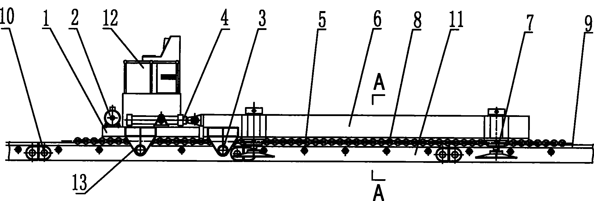
本发明为解决上述提出的问题所采用的技术方案为:包括有轨道底架11,在轨道底架的上面两侧安设平行延伸的导轨9,导轨上敷设有滚轮组8,滚轮组上方搁置承载架6,承载架的一端连接动力车1,动力车两侧配置锁定装置13,锁定装置与轨道底架两侧设置的步进锁孔5相配置;所述承载架的两侧设置有与轨道底架两侧的步进锁孔相配置的承架锁定装置3,承载架的底部安设有上导轨14与滚轮组8相配置;所述的动力车1包括有车架、操纵台12和安设在车架两侧的同步伸缩油缸4,同步伸缩油缸的活塞杆端与承载架相连。The technical solution adopted by the present invention to solve the above-mentioned problems is as follows: a track chassis 11 is included, and guide rails 9 extending in parallel are installed on both sides above the track chassis, and a roller set 8 is laid on the guide rail, and the roller set is placed on top of the track chassis. Carrying frame 6, one end of carrying frame is connected with power car 1, and locking device 13 is configured on both sides of power car, and locking device is configured with the stepping lock hole 5 that track chassis both sides is provided with; Both sides of described carrying frame are provided with The frame locking device 3 is equipped with the stepping lock holes on both sides of the track chassis. The bottom of the carrier frame is equipped with an upper guide rail 14 and a roller set 8. The power car 1 includes a frame and a console 12. And the synchronous telescopic oil cylinder 4 that is arranged on vehicle frame both sides, the piston rod end of synchronous telescopic oil cylinder links to each other with the bearing frame.
按上述方案,在承载架的四角还安设有顶升油缸7。According to the above scheme, jacking oil cylinders 7 are also installed at the four corners of the bearing frame.
按上述方案,所述的轨道底架由2个或2个以上的轨道底架前后续接而成,在轨道底架11的两端设置有活动接头10,以便于两个轨道底架的前后续接和脱开。According to the above scheme, the track underframe is formed by connecting two or more track underframes before and after, and movable joints 10 are arranged at both ends of the track underframe 11, so as to facilitate the front and back of the two track underframes. Then connect and disconnect.
本发明的使用过程为:将所需平移的大件货物放置于承载架6上,通过顶升系统将货物与承载架6升起,然后敷设轨道底架11和滚轮组8,尔后顶升油缸7卸荷使货物落于轨道底架11上,并将动力车1与承载架6相连,开始平移作业。平移开始时,动力车1的同步伸缩油缸4处于缩回状态,同时通过锁定装置13将动力车锁定于轨道底架上,再开启同步伸缩油缸来推动承载架沿导轨9向前移动,同步伸缩油缸伸出到位后,将承载架锁定,松开动力车的锁定装置,使动力车前移且使伸缩油缸缩回,进行下一次的推进,以此往复循环,使承载架不断推进;由于采用滚轮结构,使得移动阻力大大减少。当前段的轨道底架到头时,通过活动接头将后段的轨道底架卸下续接到前端,以使导轨继续向前延伸,放置货物的承载架在动力车的推动下不断前行,直至运抵到位。移动到位后,通过承载架四角的顶升油缸7将承载架及货物向上顶升,使轨道底架等腾空并抽离现场,用垫块等将大件货物垫实,松开顶升油缸,撤出承载架,即完成大件货物的平移搬迁任务。The application process of the present invention is as follows: place the large-sized goods that need translation on the carrier 6, lift the goods and the carrier 6 through the jacking system, then lay the track base 11 and the roller group 8, and then lift the oil cylinder 7 Unloading makes the goods fall on the track underframe 11, and connects the power car 1 with the bearing frame 6, and starts the translation operation. At the beginning of the translation, the synchronous telescopic oil cylinder 4 of the power car 1 is in the retracted state, and at the same time, the power car is locked on the track chassis through the locking device 13, and then the synchronous telescopic oil cylinder is opened to push the carrier to move forward along the guide rail 9, synchronously telescopic After the oil cylinder is stretched out in place, lock the carrier frame, loosen the locking device of the power car, move the power car forward and retract the telescopic oil cylinder for the next push, and reciprocate in this way to make the carrier frame continue to advance; due to the use of The roller structure greatly reduces the movement resistance. When the track chassis of the front section reaches the end, the track chassis of the rear section is removed and connected to the front end through the movable joint, so that the guide rail continues to extend forward, and the load-carrying frame for placing the goods continues to move forward under the push of the power car until Arrived in place. After moving in place, use the lifting cylinders 7 at the four corners of the carrier frame to lift the carrier frame and the goods upwards, so that the track chassis and others are vacated and pulled away from the site, and the large goods are padded with pads, etc., and the jacking cylinder is released. Withdraw the carrier to complete the task of translational relocation of large cargo.
本发明的有益效果在于:1、结构紧凑、机械化程度较高,能够通过顶升来平移和搬迁大型集装箱、大型设备等大吨位的大件货物;2、实施简便,大大节省了繁重的人工操作,安全可靠性高,且搬移的效率较高;特别适于在一些设备简陋的港口、工地和仓库使用。The beneficial effects of the present invention are as follows: 1. The structure is compact and the degree of mechanization is high, and large-tonnage and bulky goods such as large containers and large-scale equipment can be translated and moved by jacking; 2. The implementation is simple and the heavy manual operation is greatly saved , high safety and reliability, and high moving efficiency; it is especially suitable for use in ports, construction sites and warehouses with poor equipment.
附图说明Description of drawings
图1为本发明一个实施例的正视结构图。Fig. 1 is a front structural diagram of an embodiment of the present invention.
图2为图1的俯视图。FIG. 2 is a top view of FIG. 1 .
图3为图1中的A-A剖视图。Fig. 3 is a sectional view of A-A in Fig. 1 .
图4为本发明动力车的侧视图。Fig. 4 is a side view of the power car of the present invention.
具体实施方式Detailed ways
以下结合附图进一步说明本发明的实施例,包括有轨道底架11,轨道底架由两根平行延伸的纵向箱梁和横向的连接撑杆相连构成,在轨道底架上面两侧的纵向箱梁上安设平行延伸的导轨9,所述的轨道底架由3~6个的单个轨道底架前后续接而成,在轨道底架11的两端设置有活动接头10,活动接头由连接板和锁片构成,以便于两个轨道底架的前后续接和脱开;在轨道底架两侧设置的步进锁孔5;导轨9上敷设有滚轮组8,滚轮组由多个滚轮侧向链接而成;滚轮组上方搁置承载架6,承载架由两根纵梁和横梁连接构成,承载架的两侧设置有与轨道底架两侧的步进锁孔5相配置的承架锁定装置3,承架锁定装置包括油缸和与其相连的销轴,在承载架的底部安设有上导轨14与滚轮组8相配置,以使承载架能在轨道底架上沿导轨自由移动;在承载架的四角横梁的延伸端安设有顶升油缸7。在承载架的后端连接动力车1,所述的动力车1包括有车架、操纵台12、电动油泵2和安设铰接在车架两侧的同步伸缩油缸4,车架底部两侧安设有上导轨15与轨道底架上的滚轮组8相配置,同步伸缩油缸的活塞杆端与承载架6后端相铰接,动力车两侧配置锁定装置13,锁定装置包括油缸和与其相连的销轴,锁定装置与轨道底架两侧设置的步进锁孔5相配置,用于动力与轨道底架的相对锁定,以推动承载架前移。The embodiment of the present invention will be further described below in conjunction with the accompanying drawings, including a track chassis 11. The track chassis is composed of two parallel longitudinal box girders and transverse connecting braces. The longitudinal boxes on both sides above the track chassis The guide rails 9 extending in parallel are installed on the beam, and the track chassis is formed by 3 to 6 single track chassis connected before and after. The two ends of the track chassis 11 are provided with movable joints 10, and the movable joints are composed of connecting plates and The lock piece is formed to facilitate the connection and disengagement of the front and rear of the two track chassis; the stepping lock holes 5 are arranged on both sides of the track chassis; the guide rail 9 is laid with a roller group 8, and the roller group consists of a plurality of rollers. It is formed by linking; the carrier frame 6 is placed above the roller group, and the carrier frame is composed of two longitudinal beams and beams connected. The two sides of the carrier frame are provided with the frame locking device configured with the stepping lock holes 5 on both sides of the track chassis. 3. The support frame locking device includes an oil cylinder and a pin shaft connected to it, and an upper guide rail 14 is arranged on the bottom of the support frame to be configured with the roller group 8, so that the support frame can move freely along the guide rail on the track chassis; The extension end of the four-corner crossbeam of frame is equipped with jacking oil cylinder 7. The power car 1 is connected to the rear end of the bearing frame, and the power car 1 includes a vehicle frame, a console 12, an electric oil pump 2 and a synchronous telescopic oil cylinder 4 hinged on both sides of the vehicle frame. The upper guide rail 15 is configured with the roller group 8 on the track chassis, the piston rod end of the synchronous telescopic oil cylinder is hinged with the rear end of the carrier frame 6, and locking devices 13 are arranged on both sides of the power car. The locking device includes an oil cylinder and a The pin shaft and the locking device are configured with the stepping lock holes 5 provided on both sides of the track underframe, and are used for relative locking between the power and the track underframe to push the carrier forward.
Claims (4)
Priority Applications (1)
| Application Number | Priority Date | Filing Date | Title |
|---|---|---|---|
| CN2007100522567A CN101058372B (en) | 2007-05-25 | 2007-05-25 | Large cargo translation device |
Applications Claiming Priority (1)
| Application Number | Priority Date | Filing Date | Title |
|---|---|---|---|
| CN2007100522567A CN101058372B (en) | 2007-05-25 | 2007-05-25 | Large cargo translation device |
Publications (2)
| Publication Number | Publication Date |
|---|---|
| CN101058372A CN101058372A (en) | 2007-10-24 |
| CN101058372B true CN101058372B (en) | 2010-12-22 |
Family
ID=38864709
Family Applications (1)
| Application Number | Title | Priority Date | Filing Date |
|---|---|---|---|
| CN2007100522567A Expired - Fee Related CN101058372B (en) | 2007-05-25 | 2007-05-25 | Large cargo translation device |
Country Status (1)
| Country | Link |
|---|---|
| CN (1) | CN101058372B (en) |
Cited By (1)
| Publication number | Priority date | Publication date | Assignee | Title |
|---|---|---|---|---|
| CN102180284A (en) * | 2011-04-15 | 2011-09-14 | 温州合力建设机械有限公司 | Trackless self-jacking sliding plate dolly |
Families Citing this family (15)
| Publication number | Priority date | Publication date | Assignee | Title |
|---|---|---|---|---|
| CN102069998B (en) * | 2010-12-15 | 2012-09-05 | 重庆大学 | Feeding conveyer for machining of large workpiece |
| CN102408017B (en) * | 2011-07-25 | 2013-05-22 | 河北二十冶工程技术有限公司 | Vehicle loading method for large-scale tank body |
| CN102514759A (en) * | 2011-12-14 | 2012-06-27 | 福州宝井钢材有限公司 | Novel left-right movable discharging device |
| CN102491103A (en) * | 2011-12-28 | 2012-06-13 | 中国海洋石油总公司 | Construction site thin and long single sheet transfer process and equipment |
| CN102837941B (en) * | 2012-09-20 | 2014-08-06 | 济钢集团有限公司 | Clamping and moving device of vertical continuous casting plate blank |
| CN103832796B (en) * | 2012-11-22 | 2017-04-26 | 柳溁铉 | Horizontal moving method and device for conveyer loaded with large-tonnage weights |
| CN104002117B (en) * | 2014-06-12 | 2016-08-17 | 湘潭电机股份有限公司 | A kind of frock dismantled in narrow space and install large component |
| CN106080836B (en) * | 2016-07-12 | 2018-02-02 | 上海华龙测试仪器股份有限公司 | The floating type servo-drive workbench of sample presentation dolly |
| CN106379704B (en) * | 2016-11-01 | 2018-08-10 | 山东电力建设第一工程公司 | A kind of translation that pushes and pulls of large scale equipment turns to construction system |
| CN107176478B (en) * | 2017-04-21 | 2019-04-23 | 浙江双友物流器械股份有限公司 | A container loading and unloading device |
| CN107364815A (en) * | 2017-09-14 | 2017-11-21 | 宁夏共享精密加工有限公司 | A kind of casting handling device of large-scale vertical lathe workbench |
| CN108544474A (en) * | 2018-05-16 | 2018-09-18 | 苏州奥曼恩自动化科技有限公司 | A kind of high regular of accurately copper coin circuit |
| CN109533847B (en) * | 2018-12-27 | 2020-11-24 | 中铁隧道集团二处有限公司 | A transfer machine for the upper and lower tracks of the roadheader feeder |
| CN111439609A (en) * | 2020-05-22 | 2020-07-24 | 湖北中投国际商贸物流发展有限公司 | Hydraulic translation large-scale equipment device |
| CN112320238B (en) * | 2020-11-05 | 2025-08-05 | 中建三局第二建设工程有限责任公司 | Heat absorber sliding device |
Citations (5)
| Publication number | Priority date | Publication date | Assignee | Title |
|---|---|---|---|---|
| US3857501A (en) * | 1972-02-05 | 1974-12-31 | Fordertechnische Forschungsgmb | Apparatus for loading containers with cargo |
| GB1568308A (en) * | 1977-07-27 | 1980-05-29 | Suris L | Container handling installations |
| DE4432911C1 (en) * | 1994-09-15 | 1995-11-02 | Gottfried Perdolt | Train loading and unloading device |
| CN1156432A (en) * | 1994-08-22 | 1997-08-06 | 小亚历山大·法勒 | Method and apparatus for cargo forwarding |
| CN2263089Y (en) * | 1996-07-09 | 1997-09-24 | 刘淑媛 | Loading and unloading device for transport vehicle |
-
2007
- 2007-05-25 CN CN2007100522567A patent/CN101058372B/en not_active Expired - Fee Related
Patent Citations (5)
| Publication number | Priority date | Publication date | Assignee | Title |
|---|---|---|---|---|
| US3857501A (en) * | 1972-02-05 | 1974-12-31 | Fordertechnische Forschungsgmb | Apparatus for loading containers with cargo |
| GB1568308A (en) * | 1977-07-27 | 1980-05-29 | Suris L | Container handling installations |
| CN1156432A (en) * | 1994-08-22 | 1997-08-06 | 小亚历山大·法勒 | Method and apparatus for cargo forwarding |
| DE4432911C1 (en) * | 1994-09-15 | 1995-11-02 | Gottfried Perdolt | Train loading and unloading device |
| CN2263089Y (en) * | 1996-07-09 | 1997-09-24 | 刘淑媛 | Loading and unloading device for transport vehicle |
Non-Patent Citations (1)
| Title |
|---|
| JP特开平10-194464A 1998.07.28 |
Cited By (2)
| Publication number | Priority date | Publication date | Assignee | Title |
|---|---|---|---|---|
| CN102180284A (en) * | 2011-04-15 | 2011-09-14 | 温州合力建设机械有限公司 | Trackless self-jacking sliding plate dolly |
| CN102180284B (en) * | 2011-04-15 | 2012-07-25 | 温州合力建设机械有限公司 | Trackless self-jacking sliding plate dolly |
Also Published As
| Publication number | Publication date |
|---|---|
| CN101058372A (en) | 2007-10-24 |
Similar Documents
| Publication | Publication Date | Title |
|---|---|---|
| CN101058372A (en) | Large cargo translating device | |
| US9533723B2 (en) | Mounting structure with storable transport system | |
| US9889908B2 (en) | Skidding system for an offshore installation or vessel | |
| US9840852B2 (en) | Mobile support apparatus and method of using same | |
| CN105264165B (en) | Cantilever for mobile platform slides framework | |
| US20140262562A1 (en) | Rig walking system with cantilever-mounted lifting jack assemblies | |
| CN103835727A (en) | Extended type multi-platform railway tunnel operation trolley | |
| CA2871406C (en) | Mounting structure with storable transport system | |
| CN203783592U (en) | Extended multi-platform railway tunnel operating trolley | |
| CN114293474A (en) | Carrying support and high-speed rail bridge girder erection machine transferring method | |
| CN220101294U (en) | A steel bar trolley | |
| CN210659920U (en) | Pulling type drilling machine derrick base structure | |
| CN105129676B (en) | A kind of handling system of container | |
| CN204956486U (en) | Shield method tunnel construction shield constructs horizontal translation device of board car | |
| CN102408017B (en) | Vehicle loading method for large-scale tank body | |
| CN213228454U (en) | Prefabricated bridge transportation reinforcing apparatus of festival section | |
| RU2106295C1 (en) | Boom of high load capacity truck crane | |
| CN207645605U (en) | A kind of truck handler | |
| CN110562848A (en) | A high-low position conversion device for box girder transportation | |
| CN205574959U (en) | Ball valve telescopic joint floor truck | |
| JP5843643B2 (en) | Assembly equipment for long steel plate cell and method for moving long steel plate cell | |
| CN115976894A (en) | A method for replacing track slabs of ballastless lines | |
| CN209892201U (en) | Station-crossing device of shield machine host | |
| CN211004279U (en) | Counterweight self-loading and unloading device for truck crane | |
| CN205601805U (en) | Special -purpose vehicle hydraulic support device |
Legal Events
| Date | Code | Title | Description |
|---|---|---|---|
| C06 | Publication | ||
| PB01 | Publication | ||
| C10 | Entry into substantive examination | ||
| SE01 | Entry into force of request for substantive examination | ||
| C14 | Grant of patent or utility model | ||
| GR01 | Patent grant | ||
| CF01 | Termination of patent right due to non-payment of annual fee | ||
| CF01 | Termination of patent right due to non-payment of annual fee |
Granted publication date: 20101222 |