CN100440562C - Tuning fork style piezo-vibration sheet and its installation - Google Patents
Tuning fork style piezo-vibration sheet and its installation Download PDFInfo
- Publication number
- CN100440562C CN100440562C CNB200410058590XA CN200410058590A CN100440562C CN 100440562 C CN100440562 C CN 100440562C CN B200410058590X A CNB200410058590X A CN B200410058590XA CN 200410058590 A CN200410058590 A CN 200410058590A CN 100440562 C CN100440562 C CN 100440562C
- Authority
- CN
- China
- Prior art keywords
- fork
- tuning
- type piezoelectric
- piezoelectric vibration
- vibration piece
- Prior art date
- Legal status (The legal status is an assumption and is not a legal conclusion. Google has not performed a legal analysis and makes no representation as to the accuracy of the status listed.)
- Active
Links
- 238000009434 installation Methods 0.000 title claims description 89
- 230000000116 mitigating effect Effects 0.000 claims abstract description 74
- 238000000034 method Methods 0.000 claims abstract description 11
- 238000004806 packaging method and process Methods 0.000 claims description 68
- NJPPVKZQTLUDBO-UHFFFAOYSA-N novaluron Chemical compound C1=C(Cl)C(OC(F)(F)C(OC(F)(F)F)F)=CC=C1NC(=O)NC(=O)C1=C(F)C=CC=C1F NJPPVKZQTLUDBO-UHFFFAOYSA-N 0.000 claims description 39
- 230000005484 gravity Effects 0.000 claims description 17
- 238000005538 encapsulation Methods 0.000 claims description 12
- 230000015572 biosynthetic process Effects 0.000 claims description 7
- 230000010355 oscillation Effects 0.000 abstract description 16
- 230000003116 impacting effect Effects 0.000 description 26
- 238000010586 diagram Methods 0.000 description 18
- 238000012360 testing method Methods 0.000 description 13
- 230000035939 shock Effects 0.000 description 10
- 239000000853 adhesive Substances 0.000 description 8
- 230000001070 adhesive effect Effects 0.000 description 8
- 238000013461 design Methods 0.000 description 6
- 230000000694 effects Effects 0.000 description 4
- 238000005530 etching Methods 0.000 description 4
- 238000000605 extraction Methods 0.000 description 4
- PCHJSUWPFVWCPO-UHFFFAOYSA-N gold Chemical compound [Au] PCHJSUWPFVWCPO-UHFFFAOYSA-N 0.000 description 4
- 230000003534 oscillatory effect Effects 0.000 description 4
- 238000003466 welding Methods 0.000 description 4
- 239000013078 crystal Substances 0.000 description 3
- 238000006073 displacement reaction Methods 0.000 description 3
- 235000014676 Phragmites communis Nutrition 0.000 description 2
- 239000012141 concentrate Substances 0.000 description 2
- 239000012467 final product Substances 0.000 description 2
- 239000011521 glass Substances 0.000 description 2
- 238000002844 melting Methods 0.000 description 2
- 239000012528 membrane Substances 0.000 description 2
- 239000002184 metal Substances 0.000 description 2
- 229920001296 polysiloxane Polymers 0.000 description 2
- 229910000679 solder Inorganic materials 0.000 description 2
- 241001413866 Diaphone Species 0.000 description 1
- 238000005452 bending Methods 0.000 description 1
- 239000011248 coating agent Substances 0.000 description 1
- 238000000576 coating method Methods 0.000 description 1
- 238000005516 engineering process Methods 0.000 description 1
- 230000005764 inhibitory process Effects 0.000 description 1
- 238000012423 maintenance Methods 0.000 description 1
- 239000000463 material Substances 0.000 description 1
- 238000012986 modification Methods 0.000 description 1
- 230000004048 modification Effects 0.000 description 1
- 238000005476 soldering Methods 0.000 description 1
Images


Classifications
-
- H—ELECTRICITY
- H03—ELECTRONIC CIRCUITRY
- H03H—IMPEDANCE NETWORKS, e.g. RESONANT CIRCUITS; RESONATORS
- H03H9/00—Networks comprising electromechanical or electro-acoustic devices; Electromechanical resonators
- H03H9/15—Constructional features of resonators consisting of piezoelectric or electrostrictive material
- H03H9/21—Crystal tuning forks
-
- H—ELECTRICITY
- H03—ELECTRONIC CIRCUITRY
- H03H—IMPEDANCE NETWORKS, e.g. RESONANT CIRCUITS; RESONATORS
- H03H9/00—Networks comprising electromechanical or electro-acoustic devices; Electromechanical resonators
- H03H9/02—Details
- H03H9/05—Holders; Supports
- H03H9/09—Elastic or damping supports
Abstract
Provided is a tuning fork type piezo-electric oscillation piece for preventing the collision of a package for mounting the tuning fork piezo-electric piece with oscillation arms even when an impact is added to the tuning fork piezo-electric oscillation piece, and to provide a method for mounting the tuning fork-type piezo-electric oscillation piece. The tuning fork piezo-electric oscillation piece 10 includes: a tuning fork piezo-electric oscillation piece main body 16 having a plurality of oscillation arms 14; a short side part 18 which is formed along a direction to be crossed with the longitudinal direction of the main body 16 and is connected to the main body 16; and long side parts 20 which are formed along the longitudinal direction of the main body 16 from the short side part 18 and are provided with an impact mitigating part 22.
Description
Technical field
The present invention relates to the installation method of a kind of tuning-fork-type piezoelectric vibration piece and tuning-fork-type piezoelectric vibration piece, particularly be suitable for preventing to cause the installation method of the tuning-fork-type piezoelectric vibration piece of vibrating reed breakage because of impact.
Background technology
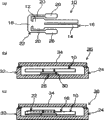
Surface installing type tuning-fork-type piezoelectric vibration piece has the structure of extending shaker arm from an end of base portion, perhaps the tuning-fork-type piezoelectric vibration piece main body of extending shaker arm by a end from base portion be connected with base portion and tuning-fork-type piezoelectric vibration piece main body be surrounded as the structure that the support portion of frame shape constitutes.Fig. 4 and Fig. 5 are the key diagrams of the tuning-fork-type piezoelectric vibration piece of expression conventional art.Fig. 4 (a) and Fig. 5 (a) are the vertical views of expression tuning-fork-type piezoelectric vibration piece, and Fig. 4 (b) and Fig. 5 (b) are the cutaway view of expression when packaging body is installed the tuning-fork-type piezoelectric vibration piece.When being installed in the tuning-fork-type piezoelectric vibration piece 112 that is made of base portion 110 and shaker arm 111 on the packaging body 113, it is fixing to utilize connection electrode that is located at base portion 110 back sides and the encapsulation side installing electrodes 114 (with reference to Fig. 4) that is located at packaging body 113 conductive adhesive 115 to engage.And when the tuning-fork-type piezoelectric vibration piece 124 that the support portion 123 that is surrounded tuning-fork-type piezoelectric vibration piece main body 122 by tuning-fork-type piezoelectric vibration piece main body 122 that is made of base portion 120 and shaker arm 121 and frame shape is constituted is installed on the packaging body 125, utilize conductive adhesive 127 to engage the fixing connection electrode and the encapsulation side installing electrodes 126 (with reference to Fig. 5) that is located at packaging body that is located at the longitudinally two ends of support portion 123 respectively.
In addition, the tuning-fork-type piezoelectric vibration piece has by base portion, shaker arm and the structure (patent documentation 1) that constitutes from the outstanding L type branch that forms of described base portion.The described support portion that also has the tuning-fork-type piezoelectric vibration piece that constitutes in the support portion that surrounds tuning-fork-type piezoelectric vibration piece main body by tuning-fork-type piezoelectric vibration piece main body and frame shape, utilize the soldering material from all directions engage up and down as tuning-fork-type piezoelectric vibration chip architecture (patent documentation 2).
Patent documentation 1 spy opens clear 57-185717 communique
Patent documentation 2 spies open clear 54-58395 communique
But the tuning-fork-type piezoelectric vibration piece that is made of base portion and shaker arm is only supporting with packaging body and two places, thus sometimes relatively the bottom surface of packaging body the tuning-fork-type piezoelectric vibration piece is installed abreast.That is, compare with the parallel installation of the front of tuning-fork-type piezoelectric vibration piece the time, upside or downside tilt, and have the problem that discreteness is installed that produces.In addition, only support at the tuning-fork-type piezoelectric vibration piece that constitutes by base portion and shaker arm with packaging body and two places, and under the situation of the tuning-fork-type piezoelectric vibration piece that constitutes by base portion and shaker arm and support portion according to top described installation, when the intense impact that causes such as falling and impose on the tuning-fork-type piezoelectric vibration piece, the front end of shaker arm can impact packaging body sometimes.Because this impact makes shaker arm crack or breakage such as breach, has the problem of the frequency characteristic that worsens the tuning-fork-type piezoelectric vibration piece.Particularly in recent years because the miniaturization slimming of tuning-fork-type piezoelectric vibration piece has the weak problem of resistance to impact.
The tuning-fork-type piezoelectric vibration piece of patent documentation 1 record is not done record about the installation to packaging body, and finds no in tuning-fork-type vibrating reed and absorb the position of impacting etc.In addition, the tuning-fork-type piezoelectric vibration piece support portion as described above of patent documentation 2 records by the housing clamping, absorbs the position of impacting so find no.
Summary of the invention
The present invention proposes in order to address the above problem, and its objective is that the bottom surface that a kind of packaging body relatively is provided installs abreast and can prevent that shaker arm from impacting the surface installing type tuning-fork-type piezoelectric vibration piece of packaging body and the installation method of tuning-fork-type piezoelectric vibration piece.
In order to achieve the above object, tuning-fork-type piezoelectric vibration piece of the present invention is characterised in that, comprising: the tuning-fork-type piezoelectric vibration piece main body with a plurality of shaker arms; The short leg that is connected with described piezoelectric vibration piece main body that the direction of intersecting along the longitudinally with described tuning-fork-type piezoelectric vibration piece main body forms; The long leg of the capable impact of the tool that the longitudinally from described short leg along described tuning-fork-type piezoelectric vibration piece main body forms mitigation portion.When applying impact to the tuning-fork-type piezoelectric vibration piece, impact the crooked one side of mitigation portion one side up-down vibration, can relax impact thus.Therefore, tuning-fork-type piezoelectric vibration piece main body can acutely not swung, and only moves up and down slightly, can not impact packaging body.So, can prevent tuning-fork-type piezoelectric vibration piece main body impact packaging body.
And, the invention is characterized in, compare with the position of centre of gravity of the combination of described short leg and described long leg with described tuning-fork-type piezoelectric vibration piece main body, be provided with installation portion at described long leg near the front of described shaker arm.Thus, when applying impact, impact and relax quality award from the ministry bending earlier, the displacement of inhibition tuning-fork-type piezoelectric vibration piece self is impacted packaging body so can prevent tuning-fork-type piezoelectric vibration piece main body.
And, the invention is characterized in, described long leg extended towards the front of described shaker arm from described installation portion be provided with, and be provided with the support portion that is connected described long leg of the direction formation that intersects along longitudinally with described tuning-fork-type piezoelectric vibration piece main body.That is, the tuning-fork-type piezoelectric vibration piece constitutes has the frame portion that surrounds around the tuning-fork-type piezoelectric vibration piece main body, is provided with the mitigation portion that impacts at the long leg of described frame portion, is provided with the support portion at the short leg of the described frame portion of shaker arm front.By the support portion is set, when being installed on the packaging body pedestal, the support portion can be installed to the tuning-fork-type piezoelectric vibration piece.And, long leg also is installed, so the tuning-fork-type piezoelectric vibration piece is installed at three places at least.Therefore, the parallel installation tuning-fork-type in the bottom surface of packaging body pedestal piezoelectric vibration piece relatively.When applying impact to the tuning-fork-type piezoelectric vibration piece, impact the crooked one side of mitigation portion one side up-down vibration, can relax impact thus.Therefore, tuning-fork-type piezoelectric vibration piece main body only moves up and down slightly, impacts packaging body so can prevent tuning-fork-type piezoelectric vibration piece main body.
And, the invention is characterized in that described impact mitigation portion makes its at least one side thinner or thin than the width and the thickness of described long leg.In addition, described impact mitigation portion can be by being provided with hole portion at described long leg or recess forms.According to the size of tuning-fork-type piezoelectric vibration piece and position of centre of gravity etc., the thickness of mitigation portion and the size of thickness or hole portion or recess etc. are impacted in design, even apply when impacting to the tuning-fork-type piezoelectric vibration piece thus, also can utilize and impact mitigation portion and relax this impact.
And, the invention is characterized in that the direction that the front end of described long leg is intersected along the longitudinally with described tuning-fork-type piezoelectric vibration piece main body is extended and is provided with, form short leg in the front of described shaker arm, below this short leg, installation portion is set.The installation position is in the front than the more close shaker arm of center of gravity of tuning-fork-type piezoelectric vibration piece.Therefore, can utilize and impact the impact that the mitigation of mitigation portion imposes on the tuning-fork-type piezoelectric vibration piece, prevent tuning-fork-type piezoelectric vibration piece main body impact packaging body.
And, the invention is characterized in that in above-mentioned tuning-fork-type piezoelectric vibration piece, the interval of described shaker arm and described long leg is wideer than the amplitude of the vibration of the shaker arm when applying impact to the tuning-fork-type piezoelectric vibration piece.When the face direction to the tuning-fork-type piezoelectric vibration piece applies impact, impact the vibration of mitigation portion, impact the also side-to-side vibrations of while shaker arm to relax.At this moment, because the interval of shaker arm and long leg is wideer than the amplitude of shaker arm vibration, impact so can prevent shaker arm and long leg.
And, the invention is characterized in, also carry out installation more than the place at long leg.Thus, the installation position has three places at least, so the parallel installation tuning-fork-type in the bottom surface of packaging body pedestal piezoelectric vibration piece relatively.
And, the invention is characterized in, than comprising the tuning-fork-type piezoelectric vibration piece main body that constitutes by base portion and shaker arm, relax on the position of the more close shaker arm side of position of centre of gravity of tuning-fork-type piezoelectric vibration piece of impact portion, support portion each long leg is installed, and described support portion is installed.Thus, because of falling when being subjected to impacting, the preferential displacement of the base portion side of tuning-fork-type piezoelectric vibration piece can prevent shaker arm side impact packaging body.
Description of drawings
Fig. 1 is the tuning-fork-type piezoelectric vibration piece of the 1st execution mode and the key diagram of tuning-fork type piezoelectric unit.
Fig. 2 is the tuning-fork-type piezoelectric vibration piece of the 2nd execution mode and the key diagram of tuning-fork type piezoelectric unit.
Fig. 3 is the figure of variation of the tuning-fork-type piezoelectric vibration piece of explanation the 2nd execution mode.
Fig. 4 is the key diagram of the tuning-fork-type piezoelectric vibration piece with base portion and shaker arm that relates to of conventional art.
Fig. 5 is the key diagram of the tuning-fork-type piezoelectric vibration piece with base portion and shaker arm and support portion that relates to of conventional art.
Fig. 6 is the curve chart of expression Impulse Test Result.
Fig. 7 is the figure of variation of the tuning-fork type piezoelectric unit of explanation the 2nd execution mode.
Fig. 8 is the key diagram of the tuning-fork-type piezoelectric vibration piece of the 3rd execution mode.
Fig. 9 is the tuning-fork-type piezoelectric vibration piece of the 4th execution mode and the key diagram of tuning-fork type piezoelectric unit.
Figure 10 is provided in a side of the key diagram of the groove of shaker arm.
Figure 11 is the key diagram that impacts mitigation portion.
Among the figure: 10 tuning-fork-type piezoelectric vibration pieces; 12 base portions; 14 shaker arms; 16 tuning-fork-type piezoelectric vibration piece main bodys; 18 short legs; 20 long legs; 22 impact mitigation portion; 26 installation portions; 50 tuning-fork-type piezoelectric vibration pieces; 52 base portions; 54 shaker arms; 56 tuning-fork-type piezoelectric vibration piece main bodys; 58 long legs; 72 impact mitigation portion.
Embodiment
Below, the execution mode of the installation method of tuning-fork-type piezoelectric vibration piece of the present invention and tuning-fork-type piezoelectric vibration piece is described.In addition, the following stated is an embodiment of the invention only, the invention is not restricted to this.The 1st execution mode at first is described.Fig. 1 is the tuning-fork-type piezoelectric vibration piece of the 1st execution mode and the key diagram of tuning-fork type piezoelectric unit.Fig. 1 (a) is the vertical view of tuning-fork-type piezoelectric vibration piece, and Fig. 1 (b) is the cutaway view of tuning-fork type piezoelectric unit, and Fig. 1 (c) is the key diagram that explanation tuning-fork-type piezoelectric vibration piece relaxes the impact that imposes on tuning-fork type piezoelectric unit.
Tuning-fork-type piezoelectric vibration piece 10 has from an end of base portion 12 and extends shaker arm 14 and the tuning-fork-type piezoelectric vibration piece main body 16 that forms.Connecting impact mitigation portion 22 in this tuning-fork-type piezoelectric vibration piece main body 16, this impact mitigation portion 22 is made of the short leg 18 of the direction of intersecting along the longitudinally with tuning-fork-type piezoelectric vibration piece main body 16 and the long leg 20 that forms along the longitudinally of tuning-fork-type piezoelectric vibration piece main body 16 from the two ends of this short leg 18.And the interval of shaker arm 14 and long leg 20 forms wideer than the amplitude of the left and right directions of 14 vibrations of the shaker arm when applying impact to tuning-fork-type piezoelectric vibration piece 10.
Be formed for installing the installation portion 26 of tuning-fork-type piezoelectric vibration piece 10 to packaging body pedestal 24 at described long leg 20.The longitudinally of these installation portion 26 diaphone bi-fork piezoelectric oscillation sheets 10 and formation connection electrode (not shown) below installation portion 26 is set.Installation portion 26 preferably is located at the front than the more close shaker arm 14 of position of centre of gravity of the tuning-fork-type piezoelectric vibration piece 10 that has made up short leg 18 and long leg 20.In addition, the front end that present embodiment constitutes at long leg 20 is provided with installation portion 26, but may not necessarily be located at front end.
In addition, the impact mitigation portion 22 that is positioned at base portion 12 sides from installation portion 26 can adjust thickness and width, has the function that relaxes impact when impacting applying to tuning-fork-type piezoelectric vibration piece 10.
And, form exciting electrode (not shown) in the top and bottom of tuning-fork-type piezoelectric vibration piece main body 16, the conducting of this exciting electrode and described connection electrode by the extraction electrode (not shown) that is located at impact mitigation portion 22.
The tuning-fork-type piezoelectric vibration piece 10 of Gou Chenging utilizes attachment 30 to engage the described connection electrode that fixedly is located at installation portion 26 and be located at the encapsulation side installing electrodes 28 of packaging body pedestal 24 like this, thereby is installed on the packaging body pedestal 24.Attachment 30 can use the solder of conductive adhesive, conductive sheet, conductive membrane, goldleaf or gold-ashbury metal etc.If particularly use silicone series conductive adhesive, can improve thermal endurance, suppress the gas that produces from described conductive adhesive.In addition, if use goldleaf then can not produce gas, so be suitable for vacuum seal packaging body 32.In addition, under the situation that can not obtain desired conductivity degree, also can obtain conductivity by welding wire.And, in the upper surface of packaging body pedestal 24 by low-melting glass or utilize seam welding to close to cover 34, constitute tuning-fork type piezoelectric unit 36.
Below, the effect that applies the tuning-fork-type piezoelectric vibration piece 10 when the impact that forms such as falling to tuning-fork type piezoelectric unit 36 is described.When applying impact to tuning-fork type piezoelectric unit 36, impact passing to tuning-fork-type piezoelectric vibration piece 10.Tuning-fork-type piezoelectric vibration piece 10 vibrates because of impact, mainly is to have impact mitigation portion 22 vibrations of impacting alleviating function.That is, when applying impact to tuning-fork-type piezoelectric vibration piece 10, impacting mitigation portion 22 is the crooked one side of center one side up-down vibration with installation portion 26, thereby mitigation is impacted.At this moment, 16 up-down vibration under the maintenance state parallel with the bottom surface of packaging body pedestal 24 of tuning-fork-type piezoelectric vibration piece main body are not so tuning-fork-type piezoelectric vibration piece main body 16 can be impacted packaging body 32 (with reference to Fig. 1 (c)).And shaker arm 14 and long leg 20 can not impact yet.
In this formation, the impact mitigation portion 22 of tuning-fork-type piezoelectric vibration piece 10 has the function that relaxes impact, even so applying to tuning-fork type piezoelectric unit 36 when impacting, tuning-fork-type piezoelectric vibration piece 10 can not impact packaging body 32 yet and crack, breakage such as breach.Therefore, the tuning-fork-type piezoelectric vibration piece 10 of the high reliability that frequency characteristic etc. can not change because of impact can be provided.
In addition, has the i.e. function of vibration of mitigation impact owing to impact mitigation portion 22, so can make the vibration leakage attenuation that transmits from the flexural vibrations of tuning-fork-type piezoelectric vibration piece 10.Therefore, can form the crystal impedance value reduces and the good tuning-fork type piezoelectric unit 36 of vibration characteristics.
And, the interval of shaker arm 14 and long leg 20 has when applying impact to tuning-fork-type piezoelectric vibration piece 10, even swinging, shaker arm 14 do not impact the distance of long leg 20, so breakages such as shaker arm 14 and long leg 20 can not crack because of impact, breach yet.
And, can use above-mentioned tuning-fork-type piezoelectric vibration piece 10 to form tuning fork type piezoelectic oscillatory device or real-time clock.
Constitute in the present embodiment at long leg 20 installation portion 26 is set, but the long leg 20 that also can constitute a side is provided with place's installation portion, two place's installation portions are set at the opposing party's long leg 20.And, also can constitute at a side long leg 20 the above installation portion in two places is set, above everywhere installation portion is set on the whole.According to this formation, can carry out the installation parallel really with the bottom surface of packaging body pedestal 24.
Below, the 2nd execution mode is described.Fig. 2 (a) is the vertical view of tuning-fork-type piezoelectric vibration piece, and Fig. 2 (b) is the cutaway view of tuning-fork type piezoelectric unit, and Fig. 2 (c) is the key diagram that explanation tuning-fork-type piezoelectric vibration piece relaxes the impact that imposes on tuning-fork type piezoelectric unit.Tuning-fork-type piezoelectric vibration piece 50 has from an end of base portion 52 and extends shaker arm 54 and the tuning-fork-type piezoelectric vibration piece main body 56 that forms.Connecting impact mitigation portion 72 in this tuning-fork-type piezoelectric vibration piece main body 56, short leg 57 that this impact mitigation portion 72 is extended by the direction of intersecting along the longitudinally with tuning-fork-type piezoelectric vibration piece main body 56 and the long leg 58 that forms along the longitudinally of tuning-fork-type piezoelectric vibration piece main body 56 from the two ends of this short leg 57 constitute.And, connect the support portion 59 of the direction extension that intersects along longitudinally with tuning-fork-type piezoelectric vibration piece main body 56 in the front of the shaker arm 54 of long leg 58.Utilize this support portion 59 and impact mitigation portion 72 and form the structure of surrounding tuning-fork-type piezoelectric vibration piece main body 56.
At described long leg 58 installation portion is set respectively, the connection electrode (not shown) that formation is used below this installation portion when packaging body pedestal 60 is installed tuning-fork-type piezoelectric vibration piece 50.The installation portion that is provided with this connection electrode is arranged on the side (front of shaker arm 54) than the more close shaker arm 54 of position of centre of gravity of the longitudinally of tuning-fork-type piezoelectric vibration piece 50.And, described connection electrode by being located at tuning-fork-type piezoelectric vibration piece main body 56 exciting electrode (not shown) and be located at the extraction electrode (not shown) that impacts mitigation portion 72 and conducting.Support portion 59 becomes and is used for tuning-fork-type piezoelectric vibration piece 50 is installed in installation portion on the packaging body pedestal 60.This installation portion is compared with described connection electrode, can be provided with a plurality of at the long leg 58 of shaker arm 54 front.
And the interval of shaker arm 54 and long leg 58 forms wideer at the amplitude of left and right directions vibration than the shaker arm 54 when applying impact to tuning-fork-type piezoelectric vibration piece 50.Impact mitigation portion 72 and can adjust thickness and width, have the function that relaxes impact when impacting applying to tuning-fork-type piezoelectric vibration piece 50.
The tuning-fork-type piezoelectric vibration piece 50 of Gou Chenging utilizes attachment 64 to engage described connection electrode that fixedly is located at long leg 58 and the encapsulation side installing electrodes 62 that is located at packaging body pedestal 60 like this.And, be fixed on the packaging body pedestal 60 engaging of support portion 59 below by attachment 64.When engaging support portion 59 and packaging body pedestal 60, can be below support portion 59 two places at two ends apply attachment 64 and engage, also can engage by the place coating attachment 64 below support portion 59 whole.The attachment 64 that engage described connection electrode and encapsulation side installing electrodes 62 can use the solder of conductive adhesive, conductive sheet, conductive membrane, goldleaf or gold-ashbury metal etc.If particularly use silicone series conductive adhesive, can improve thermal endurance, suppress the gas that produces from described conductive adhesive.In addition, if use goldleaf then can not produce gas, so be suitable for vacuum seal packaging body 66.In addition, under the situation that can not obtain desired conductivity degree, also can obtain conductivity by welding wire.The attachment 64 that engage support portion 59 and packaging body pedestal 60 can use above-mentioned attachment, can also use the attachment that do not have conductivity.And, in the upper surface of packaging body pedestal 60 by low-melting glass or utilize seam welding to close to cover 68, constitute tuning-fork type piezoelectric unit 70.
Below, the effect that applies the tuning-fork-type piezoelectric vibration piece 50 when the impact that forms such as falling to tuning-fork type piezoelectric unit 70 is described.When applying impact to tuning-fork type piezoelectric unit 70, impact passing to tuning-fork-type piezoelectric vibration piece 50.Impact mitigation portion 72 and have the impact alleviating function, impact mitigation portion 72 is the crooked one side of a center one side up-down vibration with the position of described connection electrode.Vibrate by this and to relax the impact that passes to tuning-fork-type piezoelectric vibration piece 50.Therefore, has only the front end of shaker arm 54 of tuning-fork-type piezoelectric vibration piece 50 in up-down vibration slightly, so tuning-fork-type piezoelectric vibration piece main body 56 can not impacted packaging body 66 (with reference to Fig. 2 (c)).And shaker arm 54 and long leg 58 can not impact yet.
In this formation, the impact mitigation portion 72 of tuning-fork-type piezoelectric vibration piece 50 has the function that relaxes impact, even so when applying impact to tuning-fork type piezoelectric unit 70, impact mitigation portion 72 and relax impact, tuning-fork-type piezoelectric vibration piece main body 56 can high vibration.Therefore, tuning-fork-type piezoelectric vibration piece 50 can not impact packaging body 66 and crack, breakage such as breach.And, relax the function of impacting because the tuning-fork-type piezoelectric vibration piece has, so even also can be not damaged when making the tuning-fork-type piezoelectric vibration piece become miniaturization, slimming.And, the tuning-fork-type piezoelectric vibration piece 50 of the high reliability that frequency characteristic etc. can not change because of impact can be provided.
In addition, impact mitigation portion 72 and can make the vibration leakage attenuation that transmits from the flexural vibrations of tuning-fork-type piezoelectric vibration piece 50.Therefore, can form the crystal impedance value reduces and the good tuning-fork type piezoelectric unit 70 of vibration characteristics.
And the interval of shaker arm 54 and long leg 58 can guarantee also not impact long leg 58 applying to tuning-fork-type piezoelectric vibration piece 50 when impacting even shaker arm 54 swings, thus shaker arm 54 and long leg 58 can not impact crack, breakage such as breach.
By the installation portion of being located at long leg 58 being arranged on a side of comparing with the position of centre of gravity of the longitudinally of tuning-fork-type piezoelectric vibration piece 50 near shaker arm 54, the displacement of base portion 52 sides is preferentially taken place, when applying impact, the addendum modification that suppresses tuning-fork-type piezoelectric vibration piece 50 self, tuning-fork-type piezoelectric vibration piece 50 can not impact that packaging body cracks or breach.
And, be formed with the frame portion that surrounds tuning-fork-type piezoelectric vibration piece 50 at the tuning-fork-type piezoelectric vibration piece 50 of the 2nd execution mode, so compare, can improve mechanical strength with the tuning-fork-type piezoelectric vibration piece that does not have this frame portion.
And, can use above-mentioned tuning-fork-type piezoelectric vibration piece 50 to form tuning fork type piezoelectic oscillatory device or real-time clock.
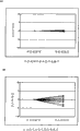
Below, the shock test of tuning-fork type piezoelectric unit 70 is described.In this shock test, the tuning-fork type piezoelectric unit that uses above-mentioned tuning-fork type piezoelectric unit 70 and do not have the prior art of impacting mitigation portion 72.Shock test is after being installed in tuning-fork type piezoelectric unit on the anchor clamps, falls respectively 10 times from the 150cm eminence in length, width and the short transverse of tuning-fork type piezoelectric unit.Fig. 6 represents the result of shock test, is benchmark with the frequency of oscillation of the tuning-fork type piezoelectric unit before the shock test, utilizes frequency change rate to represent the degrees of offset of the frequency of oscillation after the shock test.The result of the test of the above-mentioned tuning-fork type piezoelectric unit 70 of Fig. 6 (a) expression, the Impulse Test Result of the tuning-fork type piezoelectric unit of Fig. 6 (b) expression prior art.Above-mentioned tuning-fork type piezoelectric unit 70 is according to Fig. 6 (a) also almost not skew of frequency of oscillation after shock test as can be known, and the skew of obtaining the frequency of oscillation after the shock test is σ=0.221.Relative therewith, the tuning-fork type piezoelectric unit of prior art according to Fig. 6 (b) as can be known after shock test frequency of oscillation skew very big, and the skew of obtaining the frequency of oscillation after the shock test is σ=2.061.It can be said that above-mentioned tuning-fork type piezoelectric unit 70 will impact mitigation by the impact mitigation portion 72 of tuning-fork-type piezoelectric vibration piece 50, so almost not skew of frequency of oscillation.In addition, we can say the tuning-fork type piezoelectric unit of prior art owing to do not have the mitigation of impact portion, so apply impact to base portion and shaker arm, the frequency of oscillation skew is very big.
In addition, the tuning-fork type piezoelectric unit 70 of the 2nd execution mode constitutes utilization tuning-fork-type piezoelectric vibration piece 50 and encapsulation side installing electrodes 62 is electrically connected with the described installation portion of mechanical connection, and the support portion 59 that tuning-fork-type piezoelectric vibration piece 50 and packaging body base side 60 are carried out mechanical connection is installed on the packaging body pedestal 60, but also can only be installed in tuning-fork-type piezoelectric vibration piece 50 on the packaging body pedestal 60 with described installation portion.Fig. 7 represents the key diagram of variation of the tuning-fork type piezoelectric unit of the 2nd execution mode.Fig. 7 (a) is the vertical view of tuning-fork type piezoelectric unit, and Fig. 7 (b) is the cutaway view of tuning-fork type piezoelectric unit.In addition, Fig. 7 (a) records and narrates in the mode of having omitted lid.In long leg 58, installation portion 74 is set in front than the more close shaker arm 54 of the position of centre of gravity of tuning-fork-type piezoelectric vibration piece 50.This installation portion 74 forms longlyer along long leg 58, and is wire with packaging body pedestal 60 and is connected.That is, attachment 64 are set, tuning-fork-type piezoelectric vibration piece 50 is installed on the packaging body pedestal 60 in part with the dotted line among Fig. 7 (a).Thus, even support tuning-fork-type piezoelectric vibration piece 50, also tuning-fork-type piezoelectric vibration piece 50 can be mounted to parallel with the bottom surface of packaging body pedestal 60 at two places.Therefore, when applying impact to tuning-fork type piezoelectric unit 70, tuning-fork-type piezoelectric vibration piece 50 can not impact packaging body pedestal 60.
Below, the variation of the tuning-fork type piezoelectric unit of the 2nd execution mode is described.Fig. 3 represents the key diagram of the variation of tuning-fork type piezoelectric unit.Fig. 3 (a) and Fig. 3 (b) are the figure of expression the 1st variation, and Fig. 3 (a) is its vertical view, and Fig. 3 (b) is its end view.The 1st variation has the profile identical with the tuning-fork-type piezoelectric vibration piece 50 of the 2nd execution mode, but forms thinlyyer from the connection electrode 82 (installation portion 85) of long leg 80 to short leg 81.Can use method such as etch partially to process this long leg 80 and make its attenuation.Fig. 3 (c) is the figure of expression the 2nd variation.The 2nd variation makes and forms carefullyyer from the installation portion 85 that is located at long leg 80 to the short leg 81, makes from installation portion 85 to the support portion that the long leg 84 80 forms slightlyer in the inboard.Fig. 3 (d) is the figure of expression the 3rd variation.The 3rd variation makes long leg 80 form carefullyyer, only makes the installation portion 85 that is provided with connection electrode form slightlyer.Fig. 3 (e) is the figure of expression the 4th variation.The 4th variation makes and forms carefullyyer from the installation portion 85 that is located at long leg 80 to the short leg 81, makes from installation portion 85 to the support portion to form slightlyer in the outside 84.Fig. 3 (f) is the figure of expression the 5th variation.The 5th variation makes and forms carefullyyer from the installation portion 85 that is located at long leg 80 to the short leg 81, makes from installation portion 85 to the support portion 84 to form slightlyer in inboard and the outside.Fig. 3 (g) is the figure of expression the 6th variation.The 6th variation makes long leg 80 form carefullyyer, makes the installation portion 85 that is provided with connection electrode form slightlyer in the inboard, and makes from forming slightlyer to the support portion 84 in the outside near the connecting portion of base portion and shaker arm.The installation portion 85 of the 1st~the 6th variation is compared with the position of centre of gravity of tuning-fork-type piezoelectric vibration piece and is located at the shaker arm front.And installation portion 85 is than the position that is provided with attachment, and promptly connection electrode is long.Therefore, when impacting mitigation portion and vibrate because of impact, the stress of vibration concentrates on the long leg 80 that is positioned on the attachment end, but since apply the width of long leg 80 of the position of this stress form broad, so long leg 80 can not fracture.Like this, the 1st~the 6th variation can be brought into play effect and the effect identical with the tuning-fork-type piezoelectric vibration piece 50 of the 2nd execution mode.
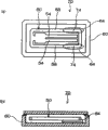
Below, the 3rd execution mode is described.Fig. 8 is the key diagram of the tuning-fork-type piezoelectric vibration piece of expression the 3rd execution mode.The tuning-fork-type piezoelectric vibration piece of the 3rd execution mode is not provided with base portion in tuning-fork-type piezoelectric vibration piece main body.Fig. 8 (a) is the vertical view with tuning-fork-type piezoelectric vibration piece of frame portion, and Fig. 8 (b) is the vertical view with tuning-fork type piezoelectric unit of frame portion.Tuning-fork-type piezoelectric vibration piece 200 shown in Fig. 8 (a) constitutes has rectangle frame portion 202, the shaker arms 208 that extend at the inboard short leg 206 that is provided with towards the opposing party of a side's of this frame portion 202 short leg 204.And the wider width of the opposing party's short leg 206 is formed for the installation portion 209 to packaging body pedestal (not shown) installation tuning-fork-type piezoelectric vibration piece 200 in its lower section.The long leg 210 of frame portion 202 becomes the mitigation portion that impacts, and this long leg 210 is adjusted thickness and width according to the size of shaker arm and position of centre of gravity etc., applying to tuning-fork-type piezoelectric vibration piece 200 when impacting, has the function (impacting mitigation portion) that relaxes this impact.This impact alleviating function can be set in the part of long leg, during this situation, can adjust the length, width, the thickness that impact alleviating function.In addition, long leg 210 can form the shape of the long leg 80 that illustrates in the variation of the 2nd execution mode.Form exciting electrode (not shown) on the shaker arm 208 of this tuning-fork-type piezoelectric vibration piece 200, form connection electrode (not shown) on installation portion 209, this connection electrode is connected to form in the encapsulation side of described packaging body pedestal installing electrodes (not shown).Described exciting electrode is connected by the extraction electrode (not shown) that is located at long leg 210 with described installing electrodes.And the part of surrounding at the with dashed lines shown in Fig. 8 (a) is provided with attachment, makes described connection electrode and described installing electrodes conducting, and tuning-fork-type piezoelectric vibration piece 200 is installed on described packaging body pedestal.Described attachment can use the attachment 30 that illustrate in the 1st execution mode.Form tuning-fork type piezoelectric unit thus.
In addition, the tuning-fork-type piezoelectric vibration piece 220 shown in Fig. 8 (b) has parallel two shaker arms 222 arranged side by side, and an end of these shaker arms 222 is connected by minor face 224.Between shaker arm 222, long leg 226 is set along shaker arm 222.The front end extension of this long leg 226 is arranged on and the direction of intersecting along the direction of shaker arm 222, and forms short leg 228.Form the support portion by this long leg 226 and short leg 228, this support portion forms the T word shape.Become installation portion 230 below the described short leg 228.Long leg 226 becomes the mitigation portion that impacts, and can adjust thickness and width according to the size of shaker arm 222 and position of centre of gravity etc.Twist in order to prevent that shaker arm 222 from applying when impacting, can consider that the size of shaker arm 222 and position of centre of gravity wait thickness and the width that designs long leg 226.Shaker arm 222 at this tuning-fork-type piezoelectric vibration piece 220 forms exciting electrode (not shown), forms the connection electrode (not shown) that is connected to form in the encapsulation side of packaging body pedestal (not shown) installing electrodes (not shown) at installation portion 230.Described exciting electrode is connected by the extraction electrode (not shown) that is located at long leg 226 with described installing electrodes.And the part of surrounding at the with dashed lines shown in Fig. 8 (b) is provided with attachment, makes described connection electrode and described installing electrodes conducting, and tuning-fork-type piezoelectric vibration piece 220 is installed on described packaging body pedestal.Described attachment can use the attachment 30 that illustrate in the 1st execution mode.Form tuning-fork type piezoelectric unit thus.
Applying to the tuning-fork type piezoelectric unit that the tuning-fork-type piezoelectric vibration piece 200,220 shown in Fig. 8 (a) or Fig. 8 (b) is installed when the impact that forms such as falling, transmit impact from described packaging body pedestal to tuning-fork-type piezoelectric vibration piece 200,220 by installation portion 209,230, but relax impact by the long leg 210,226 that has been adjusted thickness and width, shaker arm 208,222 can high vibration.Thus, tuning-fork-type piezoelectric vibration piece 200,220 can relax impact, can not crack at shaker arm 208,222, breakage such as breach.And, applying the wide distance of amplitude that has when impacting than shaker arm 208,222 vibrations, breakages such as long leg 210,226 cracks so shaker arm 208,222 can not impact, breach to tuning-fork-type piezoelectric vibration piece 200,220 between shaker arm 208,222 and the long leg 210,226.In addition, tuning-fork-type piezoelectric vibration piece 200,220 does not have base portion, so can accomplish miniaturization.
And, between shaker arm 208,222 and installation portion 209,230, be provided with long leg 210,226, so the vibration of leaking from shaker arm 208,222 is decayed at long leg 2 10,226.Therefore, can obtain the good tuning-fork type piezoelectric unit of vibration characteristics.
If the circuit to above-mentioned tuning-fork type piezoelectric unit setting is vibrated tuning-fork-type piezoelectric vibration piece 200,220 can obtain the tuning fork type piezoelectic oscillatory device.
Below, the 4th execution mode is described.Fig. 9 represents the tuning-fork-type piezoelectric vibration piece of the 4th execution mode and the key diagram of tuning-fork type piezoelectric unit.The tuning-fork-type piezoelectric vibration piece 240 of the 4th execution mode constitutes to have by base portion 242 with from this base portion 242 and extends the tuning-fork-type piezoelectric vibration piece main body 246 that a plurality of shaker arms 244 of being provided with constitute, and the frame portion 248 of rectangle is set around this tuning-fork-type piezoelectric vibration piece main body 246.One side's of frame portion 248 short leg 250 connects the other end of base portion 242.Long leg 252 in frame portion 248 is provided with impact mitigation portion 254 and compares the installation portion 256 that is positioned at shaker arm 244 front with the position of centre of gravity of tuning-fork-type piezoelectric vibration piece 240.
Described impact mitigation portion 254 forms from installation portion 256 to one sides' the short leg 250, shown in Fig. 9 (a), forms by making the attenuation that attenuates of this part.And shown in Fig. 9 (b), impacting mitigation portion 254 can be by in the part of long leg 252, promptly not only thin the but also thin part of part setting of 256 to one sides' of the installation portion from long leg 252 short leg 250 constitutes.The part that this is not only thin but also thin, the part that promptly encloses can be located near an installation portion 256 and a side's the central portion of short leg 250.In addition, the part that encloses can be formed with a plurality of at long leg 252.And the thickness of not only thin but also thin part, thickness, length can wait according to the size of tuning-fork-type piezoelectric vibration piece 240 and position of centre of gravity and design.
Connection electrode (not shown) is set below described installation portion 256, and this connection electrode can form point-like, also can form wire along long leg 252.And, when being installed on the packaging body pedestal 258, engage installation portion 256 and packaging body pedestal 258 to the tuning-fork-type piezoelectric vibration piece 240 shown in Fig. 9 (a) or Fig. 9 (b) by attachment 260.These attachment 260 can use the attachment 30 that illustrate in the 1st execution mode.Fig. 9 (c) is the cutaway view of tuning-fork type piezoelectric unit.In addition, Fig. 9 (c) is installed in tuning-fork-type piezoelectric vibration piece 240 shown in this figure (b) on the packaging body.Attachment 260 be arranged on installation portion 256 with compare with the connecting portion of not only thin but also thin part, near the front of shaker arm 244.That is, leaving the engagement position tuning-fork-type piezoelectric vibration piece 240 and the packaging body pedestal 258 of described connecting portion., if the end of attachment 260 be positioned at described connecting portion below, applying to tuning-fork-type piezoelectric vibration piece 240 when impacting and impacting 254 swings of mitigation portion, the stress that forms because of swing concentrates on described connecting portion.And, owing to make the weak strength of part not only thin but also thin in the long leg 252, so described connecting portion fractures because of described stress.But in the present embodiment, upside has installation portion 256 in the end of attachment 260, so even also can not fracture when causing stress to be concentrated because of the swing of impacting mitigation portion 254.Tuning-fork-type piezoelectric vibration piece 240 is bonded into wire at each installation portion 256 on packaging body pedestal 258, so the bottom surface of packaging body pedestal 258 is installed tuning-fork-type piezoelectric vibration piece 240 abreast relatively.And, described connection electrode is being arranged under the situation of point-like, the following of short leg 262 of shaker arm 244 front got final product as the support portion.Thus, tuning-fork-type piezoelectric vibration piece 240 is engaged at each installation portion 256 and support portion on packaging body pedestal 258, so the bottom surface of packaging body pedestal 258 is installed tuning-fork-type piezoelectric vibration piece 240 abreast relatively.
And, shown in Fig. 9 (d), impact mitigation portion 254 and also can form by hole portion 264 being set at long leg 252.The shape of described hole portion 264 can be used Any shape according to the design of impacting mitigation portion 254, for example can use circle, ellipse, quadrangle, triangle etc.And the size of hole portion 264 and configuration space also can be set arbitrarily according to the design of impacting mitigation portion 254.In addition, hole portion can form when forming tuning-fork-type piezoelectric vibration piece 240 by etching and get final product.And, also can replace hole portion 264 with recess.Described recess can form simultaneously with the groove that is located at shaker arm 244.Can be for described concave depth by only stopping the etching of described recess is adjusted arbitrarily in the process that forms described groove in etching.Described recess can only be formed on the top of long leg 252 or below, also can be formed on the two sides.
Applying to the tuning-fork type piezoelectric unit that above-mentioned tuning-fork-type piezoelectric vibration piece 240 is installed when the impact that forms such as falling, impact passes to tuning-fork-type piezoelectric vibration piece 240 by installation portion 256 from packaging body, but the vibration by long leg 252 will be impacted mitigation, and tuning-fork-type piezoelectric vibration piece main body 246 can high vibration.Thus, tuning-fork-type piezoelectric vibration piece 240 can relax impact, can not crack at shaker arm 244, breakage such as breach.And, applying the wide distance of amplitude that has when impacting than shaker arm 244 vibrations to tuning-fork-type piezoelectric vibration piece 240 between shaker arm 244 and the long leg 252, so shaker arm 244 can not impact breakages such as long leg 252 cracks, breach.
And, between shaker arm 244 and installation portion 256, be provided with long leg 252, so the vibration of leaking from shaker arm 244 is decayed at long leg 252.Therefore, can obtain the good tuning-fork type piezoelectric unit of vibration characteristics.
If the circuit to above-mentioned tuning-fork type piezoelectric unit setting is vibrated tuning-fork-type piezoelectric vibration piece 240 then can obtain the tuning fork type piezoelectic oscillatory device.
Below, described groove is described.Described groove is located on the shaker arm, so can irrespectively be arranged on the shaker arm of all tuning-fork-type piezoelectric vibration pieces with the shape of tuning-fork-type piezoelectric vibration piece.Therefore, can on the tuning-fork-type piezoelectric vibration piece of the 1st~the 4th execution mode, form described groove.Figure 10 represents to be located at the key diagram of the groove on the shaker arm.Figure 10 (a) is the vertical view of tuning-fork-type piezoelectric vibration piece main body, and Figure 10 (b) is the cutaway view along the A-A line.In Figure 10, omit record exciting electrode etc. in addition.Groove 266 is that the longitudinally along shaker arm 268 forms on each face up and down of shaker arm 268.Therefore, the section shape of shaker arm 268 is the H type.If groove 266 is set on shaker arm 268, can improve electrical efficiency based on the shaker arm 268 of the voltage that imposes on described exciting electrode, even shaker arm 268 is shortened and/or attenuate when making miniaturization, also the vibration loss of flexural vibrations can be suppressed lower, suppress the crystal impedance value lower.
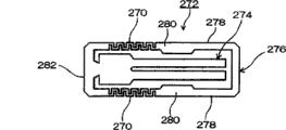
In above-mentioned the 1st~the 4th execution mode, impact mitigation portion has been described respectively, impact mitigation portion but also can substitute these with the impact mitigation portion mode of following explanation.Figure 11 represents to impact the key diagram of mitigation portion.In addition, impact an example of the tuning-fork-type piezoelectric vibration piece of mitigation portion 270, the mode that has tuning-fork-type piezoelectric vibration piece main body 274 and surround the tuning-fork-type piezoelectric vibration piece 272 of this main body rectangle frame portion 276 on every side of using is described as suitable this.This impact mitigation portion 270 is located between the short leg 282 of installation portion 280 in the long leg 278 of frame portion 276 and base portion side, and is the alternately incision and forming of inboard along the length direction of long leg 278 from long leg 278 and the outside.That is, impact mitigation portion 270 and form spring-like.Impacting the length of mitigation portion 270 and described incision width and length can be according to suitably designs such as the size of tuning-fork-type piezoelectric vibration piece 272 and position of centre of gravitys.This impact mitigation portion 270 can form when forming tuning-fork-type piezoelectric vibration piece 272 by etching simultaneously.This tuning-fork-type piezoelectric vibration piece 272 is installed on the packaging body (not shown), promptly forms tuning-fork type piezoelectric unit.And, when applying impact to tuning-fork type piezoelectric unit, impact passing to tuning-fork-type piezoelectric vibration piece 272, impact 270 swings of mitigation portion, can relax impact.In addition, the distance from tuning-fork-type piezoelectric vibration piece main body 274 to installation portion 280 becomes far away, so can make the vibration leakage attenuation of flexural vibrations, can obtain the good tuning-fork type piezoelectric unit of vibration characteristics.
Claims (11)
1. a tuning-fork-type piezoelectric vibration piece is characterized in that, comprising:
Tuning-fork-type piezoelectric vibration piece main body with a plurality of shaker arms;
The short leg that is connected with described piezoelectric vibration piece main body that the direction of intersecting along the longitudinally with described tuning-fork-type piezoelectric vibration piece main body forms; And
The long leg that longitudinally from described short leg along described tuning-fork-type piezoelectric vibration piece main body forms,
Described long leg has:
Be formed with the installation portion of connection electrode; And
Be formed between described short leg and the described installation portion, applying the crooked impact mitigation portion that propagates that impacts with mitigation of generation under the situation of impact.
2. tuning-fork-type piezoelectric vibration piece according to claim 1 is characterized in that, described installation portion is set at the front than the more close described shaker arm of position of centre of gravity of described tuning-fork-type piezoelectric vibration piece main body, described short leg and the combination of described long leg.
3. tuning-fork-type piezoelectric vibration piece according to claim 2, it is characterized in that, extend towards the front of described shaker arm from described installation portion described long leg is set, and be provided with the support portion that is connected described long leg of the direction formation that intersects along longitudinally with described tuning-fork-type piezoelectric vibration piece main body.
4. according to any described tuning-fork-type piezoelectric vibration piece in the claim 1~3, it is characterized in that described impact mitigation portion forms and makes its at least one side thinner or thin than the width and the thickness of described long leg.
5. according to any described tuning-fork-type piezoelectric vibration piece in the claim 1~3, it is characterized in that described impact mitigation portion is by being provided with hole portion at described long leg or recess forms.
6. a tuning-fork-type piezoelectric vibration piece is characterized in that, comprising:
Tuning-fork-type piezoelectric vibration piece main body with a plurality of shaker arms;
The short leg that is connected with described piezoelectric vibration piece main body that the direction of intersecting along the longitudinally with described tuning-fork-type piezoelectric vibration piece main body forms;
The long leg that longitudinally from described short leg along described tuning-fork-type piezoelectric vibration piece main body forms;
The front end of described long leg is extended setting along the direction that the longitudinally with described tuning-fork-type piezoelectric vibration piece main body intersects, be formed on the front short leg of the front of described shaker arm;
Be formed on the following installation portion of this front short leg; And
Be formed on the described long leg, applying the crooked impact mitigation portion that propagates that impacts with mitigation of generation under the situation of impact.
7. according to any described tuning-fork-type piezoelectric vibration piece in the claim 1~3,6, it is characterized in that the interval of described shaker arm and described long leg is wideer than the amplitude of shaker arm vibration when applying impact to the tuning-fork-type piezoelectric vibration piece.
8. the installation method of a tuning-fork-type piezoelectric vibration piece is characterized in that, each long leg of described tuning-fork-type piezoelectric vibration piece is installed on the position corresponding with the position of centre of gravity of tuning-fork-type piezoelectric vibration piece, and described tuning-fork-type piezoelectric vibration piece comprises:
Tuning-fork-type piezoelectric vibration piece main body with a plurality of shaker arms;
The short leg that is connected with described piezoelectric vibration piece main body that the direction of intersecting along the longitudinally with described tuning-fork-type piezoelectric vibration piece main body forms; And
The long leg that longitudinally from described short leg along described tuning-fork-type piezoelectric vibration piece main body forms,
Described long leg has:
Be formed with the installation portion of connection electrode; And
Be formed between described short leg and the described installation portion, applying the crooked impact mitigation portion that propagates that impacts with mitigation of generation under the situation of impact.
9. the installation method of tuning-fork-type piezoelectric vibration piece according to claim 8 is characterized in that, in the installation of also carrying out on the long leg more than the place.
10. a tuning-fork type piezoelectric unit is characterized in that, has tuning-fork-type piezoelectric vibration piece and packaging body pedestal,
Described tuning-fork-type piezoelectric vibration piece comprises:
Tuning-fork-type piezoelectric vibration piece main body with a plurality of shaker arms;
The short leg that is connected with described piezoelectric vibration piece main body that the direction of intersecting along the longitudinally with described tuning-fork-type piezoelectric vibration piece main body forms; And
The long leg that longitudinally from described short leg along described tuning-fork-type piezoelectric vibration piece main body forms,
Described long leg has:
Be formed with the installation portion of connection electrode; And
Be formed between described short leg and the described installation portion, applying the crooked impact mitigation portion that propagates with the mitigation impact of generation under the situation of impact,
Described packaging body pedestal is provided with encapsulation side installing electrodes, and this encapsulation side installing electrodes engages described installation portion.
11. a tuning-fork type piezoelectric unit is characterized in that, has tuning-fork-type piezoelectric vibration piece and packaging body pedestal,
The tuning-fork-type piezoelectric vibration piece comprises:
Tuning-fork-type piezoelectric vibration piece main body with a plurality of shaker arms;
The short leg that is connected with described piezoelectric vibration piece main body that the direction of intersecting along the longitudinally with described tuning-fork-type piezoelectric vibration piece main body forms;
The long leg that longitudinally from described short leg along described tuning-fork-type piezoelectric vibration piece main body forms;
The front end of described long leg is extended setting along the direction that the longitudinally with described tuning-fork-type piezoelectric vibration piece main body intersects, be formed on the front short leg of the front of described shaker arm;
Be formed on the following installation portion of this front short leg; And
Be formed on the described long leg, applying the crooked impact mitigation portion that propagates with the mitigation impact of generation under the situation of impact,
Described packaging body pedestal is provided with encapsulation side installing electrodes, and this encapsulation side installing electrodes engages described installation portion.
Applications Claiming Priority (4)
| Application Number | Priority Date | Filing Date | Title |
|---|---|---|---|
| JP2003295606 | 2003-08-19 | ||
| JP2003295606 | 2003-08-19 | ||
| JP2004141105A JP3951058B2 (en) | 2003-08-19 | 2004-05-11 | Tuning fork type piezoelectric vibrating piece |
| JP2004141105 | 2004-05-11 |
Publications (2)
| Publication Number | Publication Date |
|---|---|
| CN1585146A CN1585146A (en) | 2005-02-23 |
| CN100440562C true CN100440562C (en) | 2008-12-03 |
Family
ID=34315608
Family Applications (1)
| Application Number | Title | Priority Date | Filing Date |
|---|---|---|---|
| CNB200410058590XA Active CN100440562C (en) | 2003-08-19 | 2004-08-18 | Tuning fork style piezo-vibration sheet and its installation |
Country Status (3)
| Country | Link |
|---|---|
| US (1) | US7015631B2 (en) |
| JP (1) | JP3951058B2 (en) |
| CN (1) | CN100440562C (en) |
Cited By (1)
| Publication number | Priority date | Publication date | Assignee | Title |
|---|---|---|---|---|
| CN104410382A (en) * | 2009-09-18 | 2015-03-11 | 精工爱普生株式会社 | Vibration reed, vibrator, oscillator and electronic device |
Families Citing this family (78)
| Publication number | Priority date | Publication date | Assignee | Title |
|---|---|---|---|---|
| US8766745B1 (en) | 2007-07-25 | 2014-07-01 | Hrl Laboratories, Llc | Quartz-based disk resonator gyro with ultra-thin conductive outer electrodes and method of making same |
| US7994877B1 (en) | 2008-11-10 | 2011-08-09 | Hrl Laboratories, Llc | MEMS-based quartz hybrid filters and a method of making the same |
| JP4049017B2 (en) * | 2003-05-16 | 2008-02-20 | セイコーエプソン株式会社 | Piezoelectric vibrator |
| JP4301200B2 (en) | 2004-10-20 | 2009-07-22 | セイコーエプソン株式会社 | Piezoelectric vibrating piece and piezoelectric device |
| JP4415382B2 (en) * | 2005-01-20 | 2010-02-17 | セイコーエプソン株式会社 | Vibration gyro element, support structure of vibration gyro element, and gyro sensor |
| JP4658625B2 (en) * | 2005-01-25 | 2011-03-23 | 日本電波工業株式会社 | Angular velocity sensor and manufacturing method thereof |
| JP4415389B2 (en) * | 2005-04-27 | 2010-02-17 | セイコーエプソン株式会社 | Piezoelectric device |
| US7084556B1 (en) * | 2005-06-09 | 2006-08-01 | Eta Sa Manufacture Horlogere Suisse | Small-sized piezoelectric resonator |
| DE602005011588D1 (en) * | 2005-06-09 | 2009-01-22 | Eta Sa Mft Horlogere Suisse | Piezoelectric resonator with small dimensions |
| US7138752B1 (en) * | 2005-06-09 | 2006-11-21 | Eta Sa Manufacture Horlogere Suisse | Small-sized piezoelectric resonator |
| EP1732219B1 (en) * | 2005-06-09 | 2008-03-26 | ETA SA Manufacture Horlogère Suisse | Piezoelectric resonator and assembly comprising the same enclosed in a case |
| US7112914B1 (en) | 2005-06-09 | 2006-09-26 | Eta Sa Manufacture Horlogere Suisse | Piezoelectric resonator and assembly comprising the same enclosed in a case |
| US20060279176A1 (en) * | 2005-06-09 | 2006-12-14 | Eta Manufacture Horlogere Suisse | Small-sized piezoelectric resonator |
| EP1732220B1 (en) * | 2005-06-09 | 2008-03-26 | ETA SA Manufacture Horlogère Suisse | Small-sized piezoelectric resonator |
| DE602005012488D1 (en) * | 2005-06-09 | 2009-03-12 | Eta Sa Mft Horlogere Suisse | Compact piezoelectric resonator |
| US20090051252A1 (en) * | 2005-06-30 | 2009-02-26 | Takashi Shirai | Piezoelectric Resonator Plate And Piezolectric Resonator Device |
| US7694734B2 (en) * | 2005-10-31 | 2010-04-13 | Baker Hughes Incorporated | Method and apparatus for insulating a resonator downhole |
| JP4389924B2 (en) | 2006-11-07 | 2009-12-24 | エプソントヨコム株式会社 | Piezoelectric device |
| JP5015678B2 (en) * | 2007-07-02 | 2012-08-29 | 日本電波工業株式会社 | Piezoelectric device and piezoelectric vibrating piece |
| US10266398B1 (en) | 2007-07-25 | 2019-04-23 | Hrl Laboratories, Llc | ALD metal coatings for high Q MEMS structures |
| JP5062413B2 (en) * | 2007-11-08 | 2012-10-31 | セイコーエプソン株式会社 | Tuning fork type piezoelectric resonator element and tuning fork type piezoelectric vibrator |
| EP2071721B1 (en) * | 2007-12-13 | 2011-02-23 | ETA SA Manufacture Horlogère Suisse | Piezoelectric resonator in a small-sized package |
| US20090174289A1 (en) * | 2007-12-28 | 2009-07-09 | Adaptivenergy Llc | Magnetic impulse energy harvesting device and method |
| JP4629094B2 (en) * | 2007-12-28 | 2011-02-09 | 日本電波工業株式会社 | Piezoelectric vibrating piece, piezoelectric device and manufacturing method thereof |
| US8151640B1 (en) | 2008-02-05 | 2012-04-10 | Hrl Laboratories, Llc | MEMS on-chip inertial navigation system with error correction |
| US7802356B1 (en) | 2008-02-21 | 2010-09-28 | Hrl Laboratories, Llc | Method of fabricating an ultra thin quartz resonator component |
| JP2009206759A (en) * | 2008-02-27 | 2009-09-10 | Seiko Instruments Inc | Piezoelectric vibration chip, piezoelectric vibrator, oscillator, electronic apparatus, radio wave clock, and method of manufacturing piezoelectric vibration chip |
| WO2009116523A1 (en) * | 2008-03-18 | 2009-09-24 | シチズンホールディングス株式会社 | Piezoelectric device |
| WO2009143492A1 (en) * | 2008-05-23 | 2009-11-26 | Statek Corporation | Piezoelectric resonator |
| JP5181938B2 (en) * | 2008-09-03 | 2013-04-10 | 株式会社大真空 | Tuning fork crystal unit |
| EP2352227B1 (en) * | 2008-09-26 | 2019-08-14 | Daishinku Corporation | Tuning-fork-type piezoelectric vibrating piece and tuning-fork-type piezoelectric vibrating device |
| JP4685910B2 (en) * | 2008-09-29 | 2011-05-18 | 日本電波工業株式会社 | Piezoelectric device |
| JP4709884B2 (en) | 2008-09-29 | 2011-06-29 | 日本電波工業株式会社 | Piezoelectric vibrating piece and piezoelectric device |
| JP4714770B2 (en) * | 2008-10-06 | 2011-06-29 | 日本電波工業株式会社 | Tuning fork type piezoelectric vibrating piece and method for manufacturing tuning fork type piezoelectric vibrating piece |
| US7811862B2 (en) * | 2008-12-17 | 2010-10-12 | Infineon Technologies Ag | Thermally enhanced electronic package |
| US8067880B2 (en) * | 2008-12-27 | 2011-11-29 | Seiko Epson Corporation | Flexural vibration element and electronic component |
| US8552624B2 (en) * | 2009-09-18 | 2013-10-08 | Seiko Epson Corporation | Impact resistance vibrating reed, vibrator, oscillator, and electronic device |
| US8176607B1 (en) | 2009-10-08 | 2012-05-15 | Hrl Laboratories, Llc | Method of fabricating quartz resonators |
| JP5593979B2 (en) * | 2009-11-11 | 2014-09-24 | セイコーエプソン株式会社 | Vibrating piece, vibrator, oscillator, sensor and electronic equipment |
| US8299863B2 (en) | 2009-12-25 | 2012-10-30 | Seiko Epson Corporation | Flexural mode resonator element, resonating device, and electronic apparatus |
| US8283988B2 (en) * | 2010-02-25 | 2012-10-09 | Seiko Epson Corporation | Resonator element, resonator, oscillator, and electronic device |
| JP5782707B2 (en) * | 2010-12-01 | 2015-09-24 | セイコーエプソン株式会社 | Electronics |
| JP5732728B2 (en) * | 2010-02-25 | 2015-06-10 | セイコーエプソン株式会社 | Vibrating piece, vibrator and oscillator |
| US8692632B2 (en) * | 2010-03-17 | 2014-04-08 | Seiko Epson Corporation | Resonator element, resonator, oscillator, and electronic device |
| JP2011220997A (en) * | 2010-03-26 | 2011-11-04 | Seiko Epson Corp | Physical quantity detection element, physical quantity detection device, and electronic device |
| JP5085681B2 (en) * | 2010-03-31 | 2012-11-28 | 日本電波工業株式会社 | Piezoelectric vibrating piece, piezoelectric device, and method of manufacturing piezoelectric vibrating piece |
| JP5062784B2 (en) | 2010-03-31 | 2012-10-31 | 日本電波工業株式会社 | Tuning fork type piezoelectric vibrating piece and piezoelectric device |
| JP5085682B2 (en) * | 2010-04-26 | 2012-11-28 | 日本電波工業株式会社 | Piezoelectric device |
| JP2010246126A (en) * | 2010-04-28 | 2010-10-28 | Seiko Epson Corp | Piezoelectric vibration piece and piezoelectric device |
| US8912711B1 (en) * | 2010-06-22 | 2014-12-16 | Hrl Laboratories, Llc | Thermal stress resistant resonator, and a method for fabricating same |
| JP5585240B2 (en) * | 2010-06-25 | 2014-09-10 | セイコーエプソン株式会社 | Vibrating piece and vibrating device |
| US20120098389A1 (en) * | 2010-10-21 | 2012-04-26 | Micro Crystal Ag | Method for mounting a piezoelectric resonator in a case and packaged piezoelectric resonator |
| CN102455193A (en) * | 2010-10-26 | 2012-05-16 | 查红红 | Bowl type oscillator in open-type sensor and forming method thereof |
| US9130148B2 (en) * | 2011-02-25 | 2015-09-08 | Daishinku Corporation | Piezoelectric resonator plate, piezoelectric resonator, method for manufacturing piezoelectric resonator plate, and method for manufacturing piezoelectric resonator |
| TW201242246A (en) * | 2011-02-25 | 2012-10-16 | Seiko Epson Corp | Piezoelectric vibration element, piezoelectric vibrator, piezoelectric oscillator, vibration gyro element, vibration gyro sensor, and electronic apparatus |
| JP5911349B2 (en) * | 2012-03-28 | 2016-04-27 | 京セラクリスタルデバイス株式会社 | Crystal device |
| TWI493866B (en) * | 2012-05-10 | 2015-07-21 | Siward Crystal Technology Co Ltd | Piezoelectric components |
| JP6119134B2 (en) | 2012-07-19 | 2017-04-26 | セイコーエプソン株式会社 | Vibrating piece, vibrator, oscillator and electronic equipment |
| JP6155897B2 (en) | 2013-06-24 | 2017-07-05 | セイコーエプソン株式会社 | Vibrating piece, vibrator, electronic device, electronic device, and moving object |
| US9599470B1 (en) | 2013-09-11 | 2017-03-21 | Hrl Laboratories, Llc | Dielectric high Q MEMS shell gyroscope structure |
| JP6346423B2 (en) * | 2013-09-25 | 2018-06-20 | エスアイアイ・クリスタルテクノロジー株式会社 | Piezoelectric vibrator |
| JP6216213B2 (en) * | 2013-10-29 | 2017-10-18 | エスアイアイ・クリスタルテクノロジー株式会社 | Piezoelectric vibrating piece and piezoelectric vibrator |
| US9879997B1 (en) * | 2013-11-19 | 2018-01-30 | Hrl Laboratories, Llc | Quartz resonator with plasma etched tethers for stress isolation from the mounting contacts |
| JP6375622B2 (en) | 2013-12-27 | 2018-08-22 | セイコーエプソン株式会社 | Vibrating piece, vibrator, oscillator, electronic device, sensor and moving body |
| US9977097B1 (en) | 2014-02-21 | 2018-05-22 | Hrl Laboratories, Llc | Micro-scale piezoelectric resonating magnetometer |
| JP6636683B2 (en) * | 2014-03-07 | 2020-01-29 | エスアイアイ・クリスタルテクノロジー株式会社 | Piezoelectric vibrating reed and piezoelectric vibrator |
| US9991863B1 (en) | 2014-04-08 | 2018-06-05 | Hrl Laboratories, Llc | Rounded and curved integrated tethers for quartz resonators |
| JP5787007B2 (en) * | 2014-06-20 | 2015-09-30 | セイコーエプソン株式会社 | Vibrating piece, vibrator and oscillator |
| US10308505B1 (en) | 2014-08-11 | 2019-06-04 | Hrl Laboratories, Llc | Method and apparatus for the monolithic encapsulation of a micro-scale inertial navigation sensor suite |
| JP6450551B2 (en) * | 2014-09-30 | 2019-01-09 | エスアイアイ・クリスタルテクノロジー株式会社 | Piezoelectric vibrator element and piezoelectric vibrator |
| JP5885825B1 (en) | 2014-12-25 | 2016-03-16 | エスアイアイ・クリスタルテクノロジー株式会社 | Piezoelectric vibrator and method of manufacturing the piezoelectric vibrator |
| US10031191B1 (en) | 2015-01-16 | 2018-07-24 | Hrl Laboratories, Llc | Piezoelectric magnetometer capable of sensing a magnetic field in multiple vectors |
| JP6536783B2 (en) * | 2015-02-09 | 2019-07-03 | セイコーエプソン株式会社 | Vibrating piece, vibrator, oscillator, real time clock, electronic device, and moving body |
| WO2017110126A1 (en) * | 2015-12-21 | 2017-06-29 | 株式会社村田製作所 | Resonator and resonance device |
| US10175307B1 (en) | 2016-01-15 | 2019-01-08 | Hrl Laboratories, Llc | FM demodulation system for quartz MEMS magnetometer |
| JP6769487B2 (en) * | 2016-08-30 | 2020-10-14 | 株式会社大真空 | Crystal diaphragm and crystal vibration device |
| WO2018180861A1 (en) * | 2017-03-30 | 2018-10-04 | 株式会社大真空 | Tuning fork-type piezoelectric vibration piece, and tuning fork-type piezoelectric vibrator using said tuning fork-type piezoelectric vibration piece |
| WO2023013169A1 (en) * | 2021-08-03 | 2023-02-09 | 株式会社村田製作所 | Resonator, and resonating device |
Citations (3)
| Publication number | Priority date | Publication date | Assignee | Title |
|---|---|---|---|---|
| JPS5685921A (en) * | 1979-12-14 | 1981-07-13 | Seiko Epson Corp | Quartz oscillator |
| CN1371763A (en) * | 2001-02-19 | 2002-10-02 | 精工爱普生株式会社 | Piezoelectric element and package thereof |
| US20030067248A1 (en) * | 2001-10-09 | 2003-04-10 | Eta Sa Fabriques D'ebauches | Piezoelectric resonator and assembly comprising the same enclosed in a case |
Family Cites Families (5)
| Publication number | Priority date | Publication date | Assignee | Title |
|---|---|---|---|---|
| JPS5458395A (en) | 1977-10-19 | 1979-05-11 | Matsushima Kogyo Kk | Piezooelectric vibrator |
| JPS5685922A (en) | 1979-12-14 | 1981-07-13 | Seiko Epson Corp | Quartz oscillator |
| JPS57185717A (en) | 1981-05-12 | 1982-11-16 | Citizen Watch Co Ltd | Tuning fork type quartz oscillator |
| JP3900846B2 (en) * | 2001-03-02 | 2007-04-04 | セイコーエプソン株式会社 | Tuning fork type crystal vibrating piece, vibrator, oscillator and portable telephone device |
| JP4049017B2 (en) * | 2003-05-16 | 2008-02-20 | セイコーエプソン株式会社 | Piezoelectric vibrator |
-
2004
- 2004-05-11 JP JP2004141105A patent/JP3951058B2/en active Active
- 2004-08-12 US US10/916,602 patent/US7015631B2/en active Active
- 2004-08-18 CN CNB200410058590XA patent/CN100440562C/en active Active
Patent Citations (3)
| Publication number | Priority date | Publication date | Assignee | Title |
|---|---|---|---|---|
| JPS5685921A (en) * | 1979-12-14 | 1981-07-13 | Seiko Epson Corp | Quartz oscillator |
| CN1371763A (en) * | 2001-02-19 | 2002-10-02 | 精工爱普生株式会社 | Piezoelectric element and package thereof |
| US20030067248A1 (en) * | 2001-10-09 | 2003-04-10 | Eta Sa Fabriques D'ebauches | Piezoelectric resonator and assembly comprising the same enclosed in a case |
Cited By (2)
| Publication number | Priority date | Publication date | Assignee | Title |
|---|---|---|---|---|
| CN104410382A (en) * | 2009-09-18 | 2015-03-11 | 精工爱普生株式会社 | Vibration reed, vibrator, oscillator and electronic device |
| CN104410382B (en) * | 2009-09-18 | 2017-10-03 | 精工爱普生株式会社 | Vibrating reed, oscillator, oscillator and electronic instrument |
Also Published As
| Publication number | Publication date |
|---|---|
| CN1585146A (en) | 2005-02-23 |
| US20050062368A1 (en) | 2005-03-24 |
| JP3951058B2 (en) | 2007-08-01 |
| JP2005102138A (en) | 2005-04-14 |
| US7015631B2 (en) | 2006-03-21 |
Similar Documents
| Publication | Publication Date | Title |
|---|---|---|
| CN100440562C (en) | Tuning fork style piezo-vibration sheet and its installation | |
| JP4547788B2 (en) | Package structure of piezoelectric vibrator | |
| JP5737437B2 (en) | Vibrating piece, vibrator, and oscillator | |
| JP5348133B2 (en) | Tuning fork type piezoelectric vibrating piece and tuning fork type piezoelectric vibrating device | |
| US8723401B2 (en) | Piezoelectric device with a package including a convex part | |
| JP2006203458A (en) | Piezoelectric vibration chip and piezoelectric device using the same | |
| JPS6118885B2 (en) | ||
| JP4529143B2 (en) | Tuning fork type piezoelectric vibrating piece | |
| JP2004297198A (en) | Piezoelectric vibration chip, piezoelectric device, mobile phone utilizing piezoelectric device, and electronic apparatus utilizing piezoelectric device | |
| US7990027B2 (en) | Piezoelectric device and method for manufacturing piezoelectric device | |
| JP2007049748A5 (en) | ||
| CN102201794A (en) | Electronic device and method of manufacturing electronic device | |
| JP5004039B2 (en) | Vibrator | |
| JP5585240B2 (en) | Vibrating piece and vibrating device | |
| JP4089149B2 (en) | Piezoelectric device | |
| JP2004015441A (en) | Surface mount crystal oscillator | |
| TW201131975A (en) | Vibrating reed, vibrator, oscillator, and electronic device | |
| JP7312060B2 (en) | Circuit board with surface mount crystal oscillator | |
| JP4054575B2 (en) | Support structure of piezoelectric vibrator | |
| KR20080033882A (en) | Vibration sensor and method for manufacturing the same | |
| JP2007281572A (en) | Piezoelectric device |
Legal Events
| Date | Code | Title | Description |
|---|---|---|---|
| C06 | Publication | ||
| PB01 | Publication | ||
| C10 | Entry into substantive examination | ||
| SE01 | Entry into force of request for substantive examination | ||
| C14 | Grant of patent or utility model | ||
| GR01 | Patent grant |