JP6155897B2 - Vibrating piece, vibrator, electronic device, electronic device, and moving object - Google Patents
Vibrating piece, vibrator, electronic device, electronic device, and moving object Download PDFInfo
- Publication number
- JP6155897B2 JP6155897B2 JP2013131936A JP2013131936A JP6155897B2 JP 6155897 B2 JP6155897 B2 JP 6155897B2 JP 2013131936 A JP2013131936 A JP 2013131936A JP 2013131936 A JP2013131936 A JP 2013131936A JP 6155897 B2 JP6155897 B2 JP 6155897B2
- Authority
- JP
- Japan
- Prior art keywords
- resonator element
- vibrator
- vibrating
- vibrating piece
- vibration
- Prior art date
- Legal status (The legal status is an assumption and is not a legal conclusion. Google has not performed a legal analysis and makes no representation as to the accuracy of the status listed.)
- Expired - Fee Related
Links
- 230000007613 environmental effect Effects 0.000 claims 1
- 239000000758 substrate Substances 0.000 description 34
- 238000012986 modification Methods 0.000 description 32
- 230000004048 modification Effects 0.000 description 32
- 238000005452 bending Methods 0.000 description 23
- 230000010355 oscillation Effects 0.000 description 18
- 239000010453 quartz Substances 0.000 description 9
- VYPSYNLAJGMNEJ-UHFFFAOYSA-N silicon dioxide Inorganic materials O=[Si]=O VYPSYNLAJGMNEJ-UHFFFAOYSA-N 0.000 description 9
- 230000007423 decrease Effects 0.000 description 8
- 230000000694 effects Effects 0.000 description 8
- 239000000463 material Substances 0.000 description 7
- 238000004519 manufacturing process Methods 0.000 description 6
- 239000000919 ceramic Substances 0.000 description 5
- 238000013461 design Methods 0.000 description 5
- 238000010586 diagram Methods 0.000 description 5
- 239000010931 gold Substances 0.000 description 4
- 229910052751 metal Inorganic materials 0.000 description 4
- 239000002184 metal Substances 0.000 description 4
- PXHVJJICTQNCMI-UHFFFAOYSA-N Nickel Chemical compound [Ni] PXHVJJICTQNCMI-UHFFFAOYSA-N 0.000 description 3
- 239000000853 adhesive Substances 0.000 description 3
- 230000001070 adhesive effect Effects 0.000 description 3
- 238000004891 communication Methods 0.000 description 3
- 230000006835 compression Effects 0.000 description 3
- 238000007906 compression Methods 0.000 description 3
- 239000013078 crystal Substances 0.000 description 3
- 230000006870 function Effects 0.000 description 3
- 238000003384 imaging method Methods 0.000 description 3
- 230000003287 optical effect Effects 0.000 description 3
- BASFCYQUMIYNBI-UHFFFAOYSA-N platinum Chemical compound [Pt] BASFCYQUMIYNBI-UHFFFAOYSA-N 0.000 description 3
- 238000001039 wet etching Methods 0.000 description 3
- IJGRMHOSHXDMSA-UHFFFAOYSA-N Atomic nitrogen Chemical compound N#N IJGRMHOSHXDMSA-UHFFFAOYSA-N 0.000 description 2
- VYZAMTAEIAYCRO-UHFFFAOYSA-N Chromium Chemical compound [Cr] VYZAMTAEIAYCRO-UHFFFAOYSA-N 0.000 description 2
- ZOKXTWBITQBERF-UHFFFAOYSA-N Molybdenum Chemical compound [Mo] ZOKXTWBITQBERF-UHFFFAOYSA-N 0.000 description 2
- 229910045601 alloy Inorganic materials 0.000 description 2
- 239000000956 alloy Substances 0.000 description 2
- 230000001413 cellular effect Effects 0.000 description 2
- 239000011651 chromium Substances 0.000 description 2
- 239000010949 copper Substances 0.000 description 2
- 230000006866 deterioration Effects 0.000 description 2
- 239000011521 glass Substances 0.000 description 2
- PCHJSUWPFVWCPO-UHFFFAOYSA-N gold Chemical compound [Au] PCHJSUWPFVWCPO-UHFFFAOYSA-N 0.000 description 2
- 229910052737 gold Inorganic materials 0.000 description 2
- 239000011810 insulating material Substances 0.000 description 2
- 239000011229 interlayer Substances 0.000 description 2
- 239000007769 metal material Substances 0.000 description 2
- 238000000034 method Methods 0.000 description 2
- 229910052750 molybdenum Inorganic materials 0.000 description 2
- 239000011733 molybdenum Substances 0.000 description 2
- 239000010955 niobium Substances 0.000 description 2
- 239000003566 sealing material Substances 0.000 description 2
- 229910000679 solder Inorganic materials 0.000 description 2
- 239000010936 titanium Substances 0.000 description 2
- WFKWXMTUELFFGS-UHFFFAOYSA-N tungsten Chemical compound [W] WFKWXMTUELFFGS-UHFFFAOYSA-N 0.000 description 2
- 229910052721 tungsten Inorganic materials 0.000 description 2
- 239000010937 tungsten Substances 0.000 description 2
- WSMQKESQZFQMFW-UHFFFAOYSA-N 5-methyl-pyrazole-3-carboxylic acid Chemical compound CC1=CC(C(O)=O)=NN1 WSMQKESQZFQMFW-UHFFFAOYSA-N 0.000 description 1
- 241000251468 Actinopterygii Species 0.000 description 1
- 229910001316 Ag alloy Inorganic materials 0.000 description 1
- 229910000838 Al alloy Inorganic materials 0.000 description 1
- 229910001020 Au alloy Inorganic materials 0.000 description 1
- RYGMFSIKBFXOCR-UHFFFAOYSA-N Copper Chemical compound [Cu] RYGMFSIKBFXOCR-UHFFFAOYSA-N 0.000 description 1
- WQZGKKKJIJFFOK-GASJEMHNSA-N Glucose Natural products OC[C@H]1OC(O)[C@H](O)[C@@H](O)[C@@H]1O WQZGKKKJIJFFOK-GASJEMHNSA-N 0.000 description 1
- XEEYBQQBJWHFJM-UHFFFAOYSA-N Iron Chemical compound [Fe] XEEYBQQBJWHFJM-UHFFFAOYSA-N 0.000 description 1
- 229910013641 LiNbO 3 Inorganic materials 0.000 description 1
- BQCADISMDOOEFD-UHFFFAOYSA-N Silver Chemical compound [Ag] BQCADISMDOOEFD-UHFFFAOYSA-N 0.000 description 1
- RTAQQCXQSZGOHL-UHFFFAOYSA-N Titanium Chemical compound [Ti] RTAQQCXQSZGOHL-UHFFFAOYSA-N 0.000 description 1
- 230000032683 aging Effects 0.000 description 1
- 229910052782 aluminium Inorganic materials 0.000 description 1
- XAGFODPZIPBFFR-UHFFFAOYSA-N aluminium Chemical compound [Al] XAGFODPZIPBFFR-UHFFFAOYSA-N 0.000 description 1
- 238000013459 approach Methods 0.000 description 1
- 230000008901 benefit Effects 0.000 description 1
- 230000005540 biological transmission Effects 0.000 description 1
- 239000008280 blood Substances 0.000 description 1
- 210000004369 blood Anatomy 0.000 description 1
- 230000036772 blood pressure Effects 0.000 description 1
- 239000005388 borosilicate glass Substances 0.000 description 1
- 238000005219 brazing Methods 0.000 description 1
- 230000008859 change Effects 0.000 description 1
- 229910052804 chromium Inorganic materials 0.000 description 1
- 229910017052 cobalt Inorganic materials 0.000 description 1
- 239000010941 cobalt Substances 0.000 description 1
- GUTLYIVDDKVIGB-UHFFFAOYSA-N cobalt atom Chemical compound [Co] GUTLYIVDDKVIGB-UHFFFAOYSA-N 0.000 description 1
- 239000004020 conductor Substances 0.000 description 1
- 239000000470 constituent Substances 0.000 description 1
- 229910052802 copper Inorganic materials 0.000 description 1
- 230000006837 decompression Effects 0.000 description 1
- 238000011161 development Methods 0.000 description 1
- 230000018109 developmental process Effects 0.000 description 1
- PSHMSSXLYVAENJ-UHFFFAOYSA-N dilithium;[oxido(oxoboranyloxy)boranyl]oxy-oxoboranyloxyborinate Chemical compound [Li+].[Li+].O=BOB([O-])OB([O-])OB=O PSHMSSXLYVAENJ-UHFFFAOYSA-N 0.000 description 1
- 238000006073 displacement reaction Methods 0.000 description 1
- 230000005684 electric field Effects 0.000 description 1
- 238000002474 experimental method Methods 0.000 description 1
- 238000010304 firing Methods 0.000 description 1
- 229910000154 gallium phosphate Inorganic materials 0.000 description 1
- LWFNJDOYCSNXDO-UHFFFAOYSA-K gallium;phosphate Chemical compound [Ga+3].[O-]P([O-])([O-])=O LWFNJDOYCSNXDO-UHFFFAOYSA-K 0.000 description 1
- 239000008103 glucose Substances 0.000 description 1
- 239000003353 gold alloy Substances 0.000 description 1
- AMGQUBHHOARCQH-UHFFFAOYSA-N indium;oxotin Chemical compound [In].[Sn]=O AMGQUBHHOARCQH-UHFFFAOYSA-N 0.000 description 1
- 239000011261 inert gas Substances 0.000 description 1
- 238000005304 joining Methods 0.000 description 1
- 229910000833 kovar Inorganic materials 0.000 description 1
- 239000010410 layer Substances 0.000 description 1
- GQYHUHYESMUTHG-UHFFFAOYSA-N lithium niobate Chemical compound [Li+].[O-][Nb](=O)=O GQYHUHYESMUTHG-UHFFFAOYSA-N 0.000 description 1
- 238000010295 mobile communication Methods 0.000 description 1
- 238000012544 monitoring process Methods 0.000 description 1
- 229910021421 monocrystalline silicon Inorganic materials 0.000 description 1
- 229910052759 nickel Inorganic materials 0.000 description 1
- 229910052758 niobium Inorganic materials 0.000 description 1
- GUCVJGMIXFAOAE-UHFFFAOYSA-N niobium atom Chemical compound [Nb] GUCVJGMIXFAOAE-UHFFFAOYSA-N 0.000 description 1
- 150000004767 nitrides Chemical class 0.000 description 1
- 229910052757 nitrogen Inorganic materials 0.000 description 1
- 238000005457 optimization Methods 0.000 description 1
- 239000011224 oxide ceramic Substances 0.000 description 1
- 229910052574 oxide ceramic Inorganic materials 0.000 description 1
- 238000000059 patterning Methods 0.000 description 1
- 229920002120 photoresistant polymer Polymers 0.000 description 1
- 238000007747 plating Methods 0.000 description 1
- 229910052697 platinum Inorganic materials 0.000 description 1
- 229910021420 polycrystalline silicon Inorganic materials 0.000 description 1
- UKDIAJWKFXFVFG-UHFFFAOYSA-N potassium;oxido(dioxo)niobium Chemical compound [K+].[O-][Nb](=O)=O UKDIAJWKFXFVFG-UHFFFAOYSA-N 0.000 description 1
- 230000002265 prevention Effects 0.000 description 1
- 230000009467 reduction Effects 0.000 description 1
- 238000007650 screen-printing Methods 0.000 description 1
- VSZWPYCFIRKVQL-UHFFFAOYSA-N selanylidenegallium;selenium Chemical compound [Se].[Se]=[Ga].[Se]=[Ga] VSZWPYCFIRKVQL-UHFFFAOYSA-N 0.000 description 1
- 229910052709 silver Inorganic materials 0.000 description 1
- 239000004332 silver Substances 0.000 description 1
- GGCZERPQGJTIQP-UHFFFAOYSA-N sodium;9,10-dioxoanthracene-2-sulfonic acid Chemical compound [Na+].C1=CC=C2C(=O)C3=CC(S(=O)(=O)O)=CC=C3C(=O)C2=C1 GGCZERPQGJTIQP-UHFFFAOYSA-N 0.000 description 1
- 238000004544 sputter deposition Methods 0.000 description 1
- JBQYATWDVHIOAR-UHFFFAOYSA-N tellanylidenegermanium Chemical compound [Te]=[Ge] JBQYATWDVHIOAR-UHFFFAOYSA-N 0.000 description 1
- 229910052719 titanium Inorganic materials 0.000 description 1
- 238000007740 vapor deposition Methods 0.000 description 1
Images


Classifications
-
- H—ELECTRICITY
- H03—ELECTRONIC CIRCUITRY
- H03H—IMPEDANCE NETWORKS, e.g. RESONANT CIRCUITS; RESONATORS
- H03H9/00—Networks comprising electromechanical or electro-acoustic devices; Electromechanical resonators
- H03H9/15—Constructional features of resonators consisting of piezoelectric or electrostrictive material
- H03H9/21—Crystal tuning forks
-
- H—ELECTRICITY
- H03—ELECTRONIC CIRCUITRY
- H03H—IMPEDANCE NETWORKS, e.g. RESONANT CIRCUITS; RESONATORS
- H03H9/00—Networks comprising electromechanical or electro-acoustic devices; Electromechanical resonators
- H03H9/02—Details
- H03H9/05—Holders; Supports
- H03H9/0538—Constructional combinations of supports or holders with electromechanical or other electronic elements
- H03H9/0542—Constructional combinations of supports or holders with electromechanical or other electronic elements consisting of a lateral arrangement
-
- H—ELECTRICITY
- H03—ELECTRONIC CIRCUITRY
- H03H—IMPEDANCE NETWORKS, e.g. RESONANT CIRCUITS; RESONATORS
- H03H3/00—Apparatus or processes specially adapted for the manufacture of impedance networks, resonating circuits, resonators
- H03H3/007—Apparatus or processes specially adapted for the manufacture of impedance networks, resonating circuits, resonators for the manufacture of electromechanical resonators or networks
- H03H3/02—Apparatus or processes specially adapted for the manufacture of impedance networks, resonating circuits, resonators for the manufacture of electromechanical resonators or networks for the manufacture of piezoelectric or electrostrictive resonators or networks
- H03H2003/028—Apparatus or processes specially adapted for the manufacture of impedance networks, resonating circuits, resonators for the manufacture of electromechanical resonators or networks for the manufacture of piezoelectric or electrostrictive resonators or networks for obtaining desired values of other parameters
-
- H—ELECTRICITY
- H03—ELECTRONIC CIRCUITRY
- H03H—IMPEDANCE NETWORKS, e.g. RESONANT CIRCUITS; RESONATORS
- H03H3/00—Apparatus or processes specially adapted for the manufacture of impedance networks, resonating circuits, resonators
- H03H3/007—Apparatus or processes specially adapted for the manufacture of impedance networks, resonating circuits, resonators for the manufacture of electromechanical resonators or networks
- H03H3/02—Apparatus or processes specially adapted for the manufacture of impedance networks, resonating circuits, resonators for the manufacture of electromechanical resonators or networks for the manufacture of piezoelectric or electrostrictive resonators or networks
- H03H3/04—Apparatus or processes specially adapted for the manufacture of impedance networks, resonating circuits, resonators for the manufacture of electromechanical resonators or networks for the manufacture of piezoelectric or electrostrictive resonators or networks for obtaining desired frequency or temperature coefficient
- H03H2003/0407—Temperature coefficient
Description
本発明は、振動片、振動子、電子デバイス、電子機器及び移動体に関する。 The present invention relates to a resonator element, a vibrator, an electronic device, an electronic apparatus, and a moving body.
HDD(Hard Disk Drive)、モバイルコンピューター、あるいはICカード等の小型の情報機器や、携帯電話、スマートフォン、又はタブレット端末等の移動体通信機器等において、タイミング信号や同期信号を提供するデバイスとして、振動子や発振器等の電子デバイスが広く使用されている。
従来から、振動子や発振器として、パッケージに振動片を収容したものが知られている(例えば、特許文献1参照)。特許文献1に開示された振動片は、振動片の全長を短くし小型化を図るために、基部と、基部から互いに平行となるように並んで延出する2つの振動腕と、基部から延出し、2つの振動腕の間に位置する支持腕とを有している。
Vibration as a device that provides timing signals and synchronization signals in small information devices such as HDDs (Hard Disk Drives), mobile computers, and IC cards, and mobile communication devices such as mobile phones, smartphones, and tablet terminals Electronic devices such as children and oscillators are widely used.
2. Description of the Related Art Conventionally, vibrators and oscillators in which a resonator element is housed in a package are known (see, for example, Patent Document 1). In order to shorten the overall length of the resonator element and reduce the size, the resonator element disclosed in
しかしながら、特許文献1に開示された振動片は、更に小型化しようとして、基部の寸法(振動腕の延出方向の幅)を、例えば40μmと小さくするとQ値が4,639と著しく劣化するという問題があった。
However, when the resonator element disclosed in
本発明は、上述の課題の少なくとも一部を解決するためになされたものであり、以下の形態又は適用例として実現することが可能である。 SUMMARY An advantage of some aspects of the invention is to solve at least a part of the problems described above, and the invention can be implemented as the following forms or application examples.
[適用例1]本適用例に係る振動片は、第1の端面及び前記第1の端面の裏側の第2の端面を有する基部と、前記基部の前記第1の端面側から第1方向に延出し、前記第1方向と直交する第2方向に離間して配置されている一対の振動腕と、を含む振動片であって、
前記第1の端面と前記第2の端面との最短距離をWbとしたとき、
Q={(ρ・Cp)/(c・α2・Θ)}
×[{1+(2・ρ・Cp・We2・f/(π・k))2}
/(2・ρ・Cp・We2・f/(π・k))]
0.81≦Wb/We≦1.70
の関係を満足することを特徴とする。
但し、Qは前記振動片のQ値、fは前記振動片の振動周波数[Hz]、Weは実効幅[m]、ρは質量密度[kg/m3]、Cpは熱容量[J/(kg・K)]、cは前記Wbの方向と面内で直交する方向に関する弾性定数[N/m2]、αは前記Wbの方向と面内で直交する方向に関する熱膨張係数[1/K]、Θは環境温度[K]、kは前記Wbの方向に関する熱伝導率[W/(m・K)]。
Application Example 1 resonator element according to this application example includes a base having a second end surface of the back side of the first end surface and said first end face, first from the first end face side front Symbol of the base portion A pair of vibrating arms extending in one direction and spaced apart in a second direction orthogonal to the first direction ,
When the shortest distance between the first end surface and the second end surface is Wb ,
Q = {(ρ · C p ) / (c · α 2 · Θ)}
× [{1+ (2 · ρ · C p · We 2 · f / ( π · k ) ) 2 }
/ (2 · ρ · C p · We 2 · f / ( π · k ) ) ]]
0 . 81 ≦ Wb / We ≦ 1.7 0
It is characterized by satisfying the relationship.
Where Q is the Q value of the resonator element , f is the vibration frequency [Hz] of the resonator element, We is the effective width [m], ρ is the mass density [kg / m 3 ], and C p is the heat capacity [J / ( kg · K)], c is the elastic constant [N / m 2 ] in the direction orthogonal to the direction of Wb in the plane, and α is the thermal expansion coefficient [1 / K in the direction orthogonal to the direction of Wb in the plane. ], Θ is the ambient temperature [K], and k is the thermal conductivity [W / (m · K ) ] in the direction of Wb.
本適用例によれば、Wb/Weが0.81≦Wb/We≦1.70の関係を満足することにより、基部の第1の端面と第2の端面との寸法の小型化に起因する熱弾性損失を低減し、発振回路で安定な発振が可能となる高いQ値を有し、且つ従来設計の振動片に比べ、小型化が図れた振動片を得ることができるという効果がある。 According to this application example, when Wb / We satisfies the relationship of 0.81 ≦ Wb / We ≦ 1.70, the size of the first end surface and the second end surface of the base is reduced. There is an effect that it is possible to obtain a resonator element that has a high Q value that reduces thermoelastic loss, enables stable oscillation in an oscillation circuit, and can be downsized compared to a resonator element of conventional design.
[適用例2]上記適用例に記載の振動片において、0.91≦Wb/We≦1.30、の関係を満足することを特徴とする。 Application Example 2 In the resonator element described in the above application example, the relationship 0.91 ≦ Wb / We ≦ 1.30 is satisfied.
本適用例によれば、Wb/Weが0.91≦Wb/We≦1.30の関係を満足することにより、基部の第1の端面と第2の端面との寸法の小型化に起因する熱弾性損失を低減し、発振回路でより安定な発振が可能となる高いQ値を有し、且つ従来設計の振動片に比べ、小型化が図れた振動片を得ることができるという効果がある。 According to this application example, when Wb / We satisfies the relationship of 0.91 ≦ Wb / We ≦ 1.30, the size of the first end surface and the second end surface of the base is reduced. It has the effect of reducing the thermoelastic loss, having a high Q value that enables more stable oscillation in the oscillation circuit, and obtaining a resonator element that is smaller than conventional resonator elements. .
[適用例3]上記適用例に記載の振動片において、1.00≦Wb/We≦1.20、の関係を満足することを特徴とする。 Application Example 3 In the resonator element described in the above application example, the relationship of 1.00 ≦ Wb / We ≦ 1.20 is satisfied.
本適用例によれば、Wb/Weが1.00≦Wb/We≦1.20の関係を満足することにより、基部の第1の端面と第2の端面との寸法の小型化に起因する熱弾性損失を低減し、発振回路で更なる安定な発振が可能となる高いQ値を有し、且つ従来設計の振動片に比べ、更なる小型化が図れた振動片を得ることができるという効果がある。 According to this application example, when Wb / We satisfies the relationship of 1.00 ≦ Wb / We ≦ 1.20, the size of the first end surface and the second end surface of the base is reduced. It is possible to obtain a resonator element that has a high Q value that reduces thermoelastic loss, enables further stable oscillation in the oscillation circuit, and can be further reduced in size compared to a resonator element of conventional design. effective.
[適用例4]上記適用例に記載の振動片において、前記基部から支持腕が延出していることを特徴とする。 Application Example 4 In the resonator element according to the application example described above, a support arm extends from the base portion.
本適用例によれば、基部から支持腕が延出していることにより、振動腕の屈曲振動によって生じた振動漏れを抑制することができるので、高いQ値を有する振動片を得ることができるという効果がある。 According to this application example, since the support arm extends from the base portion, vibration leakage caused by bending vibration of the vibrating arm can be suppressed, so that a vibrating piece having a high Q value can be obtained. effective.
[適用例5]上記適用例に記載の振動片において、前記支持腕は、前記一対の振動腕の間に配置されていることを特徴とする。
Application Example 5 In the resonator element according to the application example described above, the support arm is characterized in that it is placed between the pair of vibrating arms.
本適用例によれば、第1の振動腕と第2の振動腕との間に、支持腕が配置されていることにより、振動片を支持・固定する部分が振動片の中央部となるため、振動片の全長を短くすることができ、振動片の小型化が図れるという効果がある。 According to this application example, since the support arm is disposed between the first vibrating arm and the second vibrating arm, the portion for supporting and fixing the vibrating piece becomes the central portion of the vibrating piece. The overall length of the resonator element can be shortened, and the resonator element can be reduced in size.
[適用例6]上記適用例に記載の振動片において、2つの前記支持腕を有し、平面視で、前記2つの支持腕の間に前記一対の振動腕が配置されていることを特徴とする。
Application Example 6 In the resonator element according to the application example described above, the resonator element includes the two support arms, and the pair of vibration arms is disposed between the two support arms in a plan view. To do.
本適用例によれば、第1の振動腕と第2の振動腕とを挟みこむように一対の支持腕が配置されていることにより、耐振動強度や耐落下強度に優れた振動片を得ることができるという効果がある。 According to this application example, a pair of support arms is disposed so as to sandwich the first vibrating arm and the second vibrating arm, thereby obtaining a vibrating piece having excellent vibration resistance and drop resistance. There is an effect that can be.
[適用例7]上記適用例に係る振動子は、内部に前記振動片が収納されている容器と、を備えていることを特徴とする。
Application Example 7 vibrator according to the application example described above is characterized in that it comprises a container in which the resonator element therein is housed, the.
本適用例によれば、小型化で高いQ値を有する振動片を搭載した振動子を得ることができる。 According to this application example, it is possible to obtain a vibrator on which a resonator element having a small Q and a high Q value is mounted.
[適用例8]本適用例に係る振動子は、前記容器の内部が真空であることを特徴とする。 Application Example 8 In the vibrator according to this application example, the inside of the container is a vacuum.
本適用例によれば、内部空間を真空にすることにより粘性抵抗が小さくなるので、振動片を安定して振動させることができる。 According to this application example, since the viscous resistance is reduced by evacuating the internal space, the resonator element can be stably vibrated.
[適用例9]本適用例に係る電子デバイスは、上記適用例に記載の振動片と、回路と、を備えていることを特徴とする。 Application Example 9 An electronic device according to this application example includes the resonator element according to the application example and a circuit.
本適用例によれば、小型化で高いQ値を有する振動片と振動片を安定に励振する発振回路とにより構成することができるため、安定した発振特性を有する小型の電子デバイスが得られるという効果がある。 According to this application example, a compact electronic device having a stable oscillation characteristic can be obtained because it can be configured by a small-sized vibrating piece having a high Q value and an oscillation circuit that stably excites the vibrating piece. effective.
[適用例10]本適用例に係る電子機器は、上記適用例に記載の振動片を備えていることを特徴とする。 Application Example 10 An electronic apparatus according to this application example includes the resonator element according to the application example.
本適用例によれば、小型で高いQ値を有する振動片を用いているため、安定した発振特性を有する小型の電子デバイスを備えた電子機器が構成できるという効果がある。 According to this application example, since the resonator element having a small and high Q value is used, there is an effect that an electronic apparatus including a small electronic device having stable oscillation characteristics can be configured.
[適用例11]本適用例に係る移動体は、上記適用例に記載の振動片を備えていることを特徴とする。 Application Example 11 A moving object according to this application example includes the resonator element described in the application example.
本適用例によれば、小型で高いQ値を有する振動片を備え、周波数再現性や周波数エージング特性に優れた小型の振動子を用いることができるため、安定で正確な電子制御ユニット等を備えた移動体が構成できるという効果がある。 According to this application example, since a small vibrator having a small and high Q value and having excellent frequency reproducibility and frequency aging characteristics can be used, a stable and accurate electronic control unit is provided. There is an effect that a movable body can be configured.
以下、本発明の実施の形態を図面に基づいて詳細に説明する。 Hereinafter, embodiments of the present invention will be described in detail with reference to the drawings.
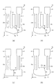
(振動子)
図1は、本発明の実施形態に係る振動子の構造を示した概略図であり、図1(a)は平面図、図1(b)は図1(a)に示すA−A線断面図である。図2は、本発明の実施形態に係る振動子に用いられている振動片の構造を示した概略図であり、図2(a)は平面図、図2(b)は図2(a)に示すB−B線断面図である。なお、図1(a)において、振動子1の内部の構成を説明する便宜上、蓋部材56を取り外した状態を図示している。また、各図では、説明の便宜上、互いに直交する3つの軸として、X軸、Y軸及びZ軸を図示している。更に、説明の便宜上、Z軸方向から見たときの平面視において、+Z軸方向の面を上面、−Z軸方向の面を下面として説明する。
(Vibrator)
1A and 1B are schematic views showing the structure of a vibrator according to an embodiment of the present invention. FIG. 1A is a plan view, and FIG. 1B is a cross-sectional view taken along line AA shown in FIG. FIG. 2A and 2B are schematic views showing the structure of the resonator element used in the vibrator according to the embodiment of the present invention. FIG. 2A is a plan view and FIG. 2B is FIG. It is a BB sectional view taken on the line. In FIG. 1A, for convenience of explanation of the internal configuration of the
図1に示すように、振動子1は、振動片2、振動片2を収容するための矩形の箱状のパッケージ本体50及びガラス、セラミック、金属等から成る蓋部材56とで構成されている。
As shown in FIG. 1, the
図1に示す振動片2は、基部12、第1、第2の振動腕21,22、錘部24,25及び支持腕23を備えた振動基板10と、この振動基板10上に設けられた駆動用の電極30と、支持腕23の下面に設けられた第1、第2導電パッド37,38と、で構成されている。
A vibrating
パッケージ本体50は、図1(b)に示すように、第1の基板51と、第2の基板52と、実装端子45と、を積層して形成されている。実装端子45は、第1の基板51の外部底面に複数備えられている。また、第1の基板51の上面の所定の位置には、図示しない貫通電極や層間配線を介して、実装端子45と電気的に導通する複数の接続電極47が設けられている。第2の基板52は中央部が除去された環状体であり、振動片2を収容するキャビティー(内部空間)70が設けられている。なお、キャビティー70内はほぼ真空の減圧空間となっている。内部空間を真空にすることにより粘性抵抗が小さくなるので、振動片2は安定して振動することができる。
As shown in FIG. 1B, the
パッケージ本体50のキャビティー70内に収納された振動片2は、支持腕23の下面に設けられた第1、第2導電パッド37,38とパッケージ本体50の第1の基板51の上面に設けられた2つの接続電極47とがそれぞれ対応するように位置合わせされ、接合部材42を介して接合されている。接合部材42は、例えば、金属あるいは半田等からなるバンプや導電性接着剤等の導電性の接合部材を用いることにより、電気的な接続を図るとともに機械的な接合を行うことができる。
The
振動基板10は、結晶材料であり、例えば、圧電基板として、水晶基板、特に、Zカット水晶板で構成されている。これにより、振動片2は、優れた振動特性を発揮することができる。Zカット水晶板とは、水晶のZ軸(光学軸)を厚さ方向とする水晶基板である。Z軸は、振動基板10の厚さ方向と一致しているのが好ましいが、常温近傍における周波数温度変化を小さくする観点からは、厚さ方向に対して若干(例えば、15°未満程度)傾けることになる。
The
なお、振動基板10は、水晶基板に限定されず、振動片を圧電駆動させる場合は、ニオブ酸リチウム(LiNbO3)、タンタル酸リチウム(LiTaO3)、リチウムテトラボレート(Li2B4O7)、ニオブ酸カリウム(KNbO3)、リン酸ガリウム(GaPO4)、ランガサイト(La3Ga5SiO14)、等がある。
また、振動片を静電駆動させる場合は、単結晶シリコン、多結晶シリコン、等がある。
Note that the
In addition, when the vibrating piece is electrostatically driven, there are single crystal silicon, polycrystalline silicon, and the like.
パッケージ本体50の、第1の基板51と第2の基板52は、絶縁性を有する材料で構成されている。このような材料としては、特に限定されず、例えば、酸化物系セラミックス、窒化物系セラミックス、炭化物系セラミックス等の各種セラミックスを用いることができる。また、パッケージ本体50に設けられた各電極、端子、あるいはそれらを電気的に接続する配線パターンや層内配線パターン等は、一般的に、タングステン(W)、モリブデン(Mo)等の金属配線材料を絶縁材料上にスクリーン印刷して焼成し、その上にニッケル(Ni)、金(Au)等のめっきを施すことにより設けられる。
The
蓋部材56は、好ましくは、光を透過する材料、例えば、ホウケイ酸ガラス等により構成されており、封止材58により接合されることで、パッケージ本体50のキャビティー70内を気密封止している。これにより、パッケージ本体50の蓋封止後において、外部からレーザー光を振動片2の先端付近に照射し、ここに設けた電極を一部蒸散させることにより、質量削減方式による周波数調整をすることができるようになっている。なお、このような周波数調整をしない場合には、蓋部材56はコバール合金等の金属材料で形成することができる。
The
(振動片)
以上、振動子1の構成について簡単に説明した。次に、振動片2について図2を参照し詳細に説明する。
振動片2の振動基板10は、図2に示すように、第1の方向であるY軸方向に面した第1の端面6と第2の端面7を有する基部12と、基部12から+Y軸方向へ突出し、且つ第2の方向であるX軸方向に並んで設けられた第1、第2の振動腕21,22と、基部12の第1の端面6から+Y軸方向へ突出するとともに、第1、第2の振動腕21,22の間に位置する支持腕23と、を有している。
(Vibration piece)
The configuration of the
As shown in FIG. 2, the
第1、第2の振動腕21,22は、X軸方向に並んで設けられており、それぞれ、基部12から+Y軸方向に延出(突出)している。また、第1、第2の振動腕21,22の先端には、錘部24,25が設けられている。このような錘部24,25を設けることによって、振動片2の小型化を図ることができたり、第1、第2の振動腕21,22の屈曲振動の周波数を低めたりすることができる。なお、錘部24,25は、必要に応じて複数の幅を有していてもよく、省略してもよい。
The first and second vibrating
また、第1、第2の振動腕21,22には、主面の表裏に、それぞれの主面に開放する有底の溝28a,28b,29a,29bが設けられている。これら溝28a,28b,29a,29bは、Y軸方向に延在して設けられており、互いに同じ形状をなしている。そのため、第1、第2の振動腕21,22は、図2(b)に示すように、略「H」状の横断面形状をなしている。
The first and second vibrating
このような溝28a,28b,29a,29bを形成することによって、屈曲振動により発生する熱が拡散(熱伝導)し難くなり、屈曲振動周波数(機械的屈曲振動周波数)fが熱緩和周波数f0より大きな領域(f>f0)である断熱的領域では、熱弾性損失を抑制することができる。なお、溝28a,28b,29a,29bは、必要に応じて設ければよく、省略してもよい。
By forming
支持腕23は、基部12から+Y軸方向に延出しており、且つ第1、第2の振動腕21,22の間に位置している。支持腕23は、長手形状であり、長手方向の全域に亘って幅(X軸方向の長さ)がほぼ一定となっている。また、支持腕23の下面に、パッケージ本体50に設けられた接続電極47と電気的に接続するための第1、第2導電パッド37,38が設けられている。更に、基部12との間に、基部12における振動が支持腕23へ伝わるのを低減するためにくびれ部18,19が設けられている。
The
(小型化)
次に、課題となっていた振動片2(振動子1)の小型化について、詳細に説明する。
図3は、振動子の等温的領域と断熱的領域について説明する模式図である。
Zカット水晶板を振動基板10とする振動子1は、外部から実装端子45、接続電極47、接合部材42、第1、第2導電パッド37,38、電極30を経由して駆動信号が印加されることにより、振動片2が所定の周波数(例えば、32.768kHz)で発振(共振)する。
振動片2は、機械的な振動周波数fが熱緩和周波数f0よりも大きくなるように設定されている(f>f0)。これにより、振動片2は、断熱的領域において屈曲振動することとなる。
(Miniaturization)
Next, the downsizing of the resonator element 2 (vibrator 1), which has been a problem, will be described in detail.
FIG. 3 is a schematic diagram for explaining an isothermal region and an adiabatic region of the vibrator.
The
The
ここで、断熱的領域について概略を説明する。図3は、断熱的領域について説明する模式図である。
一般に、屈曲振動を行う振動体の熱弾性損失(屈曲振動する振動片の圧縮部における温度上昇と伸張部における温度低下との間で発生する熱伝導により生じる振動エネルギーの損失)は、屈曲振動モードの振動片において、振動数周波数fが緩和振動数fm=1/(2・π・τ)(ただし、式中πは円周率であり、eをネイピア数とすれば、τは温度差が熱伝導によりe-1倍になるのに要する緩和時間である)と等しくなったときに最大となる。
Here, an outline of the adiabatic region will be described. FIG. 3 is a schematic diagram for explaining the adiabatic region.
In general, the thermoelastic loss of a vibrating body that performs bending vibration (vibration energy loss caused by heat conduction generated between the temperature increase in the compression part and the temperature decrease in the extension part of the vibration piece that flexes and vibrates) is the bending vibration mode. Frequency frequency f is relaxation frequency f m = 1 / (2 · π · τ) (where π is a circumference ratio and e is a Napier number, τ is a temperature difference) Is the relaxation time required to increase by e −1 times due to heat conduction).
一般に、振動腕が平板構造である場合の緩和周波数f0は、下記式(1)で求まることが知られている。
f0=(π・k)/(2・ρ・Cp・a2)・・・(1)
ここで、πは円周率、kは振動腕の振動方向(屈曲振動方向)の熱伝導率[W/(m・K)]、ρは振動腕の質量密度[kg/m3]、Cpは振動腕の熱容量[J/(kg・K)]、aは振動腕の振動方向(屈曲振動方向)の幅[m]である。
In general, it is known that the relaxation frequency f 0 when the vibrating arm has a flat plate structure is obtained by the following formula (1).
f 0 = (π · k) / (2 · ρ · C p · a 2 ) (1)
Here, π is the circumferential ratio, k is the thermal conductivity [W / (m · K ) ] in the vibration direction (bending vibration direction) of the vibrating arm, ρ is the mass density [kg / m 3 ] of the vibrating arm, C p is the heat capacity [J / (kg · K)] of the vibrating arm, and a is the width [m] of the vibrating direction (bending vibration direction) of the vibrating arm.
このQ値と周波数との関係を一般的に表すと、図3に示す線Cのようになる。図3において、Q値が極小になる周波数が熱緩和周波数f0である。
そして、振動腕が平板構造である場合には、f/f0=1を境にして、振動周波数fが熱緩和周波数f0よりも大きくなり、周波数比が1より高い領域(1<f/f0)が断熱的領域であり、周波数比が1より低い領域(1>f/f0)が等温的領域である。
The relationship between the Q value and the frequency is generally represented as a line C shown in FIG. In FIG. 3, the frequency at which the Q value is minimized is the thermal relaxation frequency f 0 .
When the vibrating arm has a flat plate structure, the region where the vibration frequency f is higher than the thermal relaxation frequency f 0 and the frequency ratio is higher than 1 (1 <f /) with f / f 0 = 1 as a boundary. f 0 ) is an adiabatic region, and a region where the frequency ratio is lower than 1 (1> f / f 0 ) is an isothermal region.
また、振動腕の表裏の関係にある両主面(屈曲振動する方向と垂直な方向に面する2つの主面)のうち少なくとも一方に溝が形成されている構造の場合の熱緩和周波数をf1とすれば、f/f1=1を境にして、振動周波数fが熱緩和周波数f1よりも大きくなり、周波数比が1より高い領域(1<f/f1)が断熱的領域であり、周波数比が1より低い領域(1>f/f1)が等温的領域である。 In addition, the thermal relaxation frequency in the case of a structure in which a groove is formed on at least one of the two main surfaces (two main surfaces facing the direction perpendicular to the bending vibration direction) in the relationship between the front and back of the vibrating arm is f If 1 , f / f 1 = 1 is the boundary, the vibration frequency f is higher than the thermal relaxation frequency f 1 , and the region where the frequency ratio is higher than 1 (1 <f / f 1 ) is the adiabatic region. A region where the frequency ratio is lower than 1 (1> f / f 1 ) is an isothermal region.
なお、振動腕の表裏の関係にある両主面のうち少なくとも一方に溝が形成されている構造の場合には、屈曲振動する振動片の圧縮部における温度上昇と伸張部における温度低下との間で発生する熱の流れる経路は、平板構造の場合に比べて長くなるから、上述の緩和時間も長くなる。即ち、熱緩和周波数f1は平板構造の熱緩和周波数f0に比べて小さくなる(f1<f0)。従って、f1<(f0×f1)1/2<f0の関係が成立つ。故に、振動腕が平板構造をしている場合には、f/f0の関係(断熱的領域)を満足することが好ましく、振動片腕の表裏主面のうち少なくとも一方に溝が形成されている構造の場合には、f/f1の関係(断熱的領域)を満足することが好ましく、更にはf>(f0×f1)1/2の関係を満たしていることが好ましく、f/f0の関係を満たしていることが最も好ましい。 In the case of a structure in which a groove is formed on at least one of the main surfaces that are in the relationship of the front and back of the vibrating arm, between the temperature rise at the compression part and the temperature drop at the extension part of the vibrating piece that flexures and vibrates Since the heat flow path generated in the above is longer than that in the case of the flat plate structure, the above relaxation time is also increased. That is, the thermal relaxation frequency f 1 is smaller than the thermal relaxation frequency f 0 of the flat plate structure (f 1 <f 0 ). Therefore, the relationship f 1 <(f 0 × f 1 ) 1/2 <f 0 is established. Therefore, when the vibrating arm has a flat plate structure, it is preferable to satisfy the relationship of f / f 0 (adiabatic region), and a groove is formed on at least one of the front and back main surfaces of the vibrating arm. In the case of the structure, it is preferable that the relationship of f / f 1 (adiabatic region) is satisfied, and it is further preferable that the relationship of f> (f 0 × f 1 ) 1/2 is satisfied. Most preferably, the relationship of f 0 is satisfied.
この関係を満たすことにより、振動片2の第1、第2の振動腕21,22で発生する熱弾性損失が小さくなる。
なお、振動腕の表裏主面のうち少なくとも一方に溝が形成されている構造の場合には、振動腕の幅(屈曲振動する方向の長さ)から(1)式によって算出されるf0と振動周波数fとの関係が、f>f0を満たしていれば、自ずとf/f1の関係を満たすことになる。
By satisfying this relationship, the thermoelastic loss generated in the first and second vibrating
In the case of a structure in which a groove is formed on at least one of the front and back main surfaces of the vibrating arm, f 0 calculated by the equation (1) from the width of the vibrating arm (the length in the direction of bending vibration) and If the relationship with the vibration frequency f satisfies f> f 0 , the relationship f / f 1 is naturally satisfied.
また、基部12においても第1、第2の振動腕21,22が、互いに離間と近接を交互に繰り返す屈曲振動をするのに伴い、基部12が、図2(c)に示すように、基部12のX軸方向の長さを梁の長さとし、基部12のY軸方向の長さを梁の幅(屈曲振動方向の長さ)とする屈曲振動体が、Y軸方向に変位を有する屈曲振動が生じる。そのため、基部12の第1の端面6と第2の端面7が圧縮と伸張を繰り返すことで、熱弾性損失が生じ、振動片2を備えた振動子1のQ値の劣化要因となっていたことが解った。
In addition, as the first and second vibrating
そこで、本発明では、振動片2の基部12における寸法と熱弾性損失との関係に着目し、第1、第2の振動腕21,22の屈曲振動に起因して生じる基部12の屈曲振動による熱弾性損失と、振動子1のQ値を基部12の屈曲振動に換算した熱弾性損失との関係を比較することに思い至った。
Therefore, in the present invention, paying attention to the relationship between the dimension of the
基部12において、最も幅(Y軸方向長さ)の狭い部分は最も剛性が低いために最も屈曲変形するので、この部分の幅方向の両端部に圧縮の変形や伸長の変形が交互に加わることによって熱が発生してこれが拡散することで発生する熱弾性損失によるQ値の劣化が最も大きい部分である。図2(c)に示すように、最も幅の狭い部分の基部12の幅Wbの方向と同じ方向の幅を有する仮想の梁13を想定し、この仮想の梁の屈曲振動によるQ値が振動子1の全体のQ値と等しくなるように設定された仮想梁の幅をWeとして定義し、これと仮想梁の屈曲振動における熱緩和周波数f0eについての関係式を建て、幅Wbと、仮想の梁の幅We(以下、実効幅と称す)との比(Wb/We)の最適化を図ることによって、振動片2の小型化に伴うQ値の劣化の低減を図った。
In the
下記式(2)は振動子1全体のQ値を表す式であり、下記式(3)は上記(1)よりQ値が極小になる周波数である熱緩和周波数f0eを表す式である。
Q={(ρ・Cp)/(c・α2・Θ)}
×[{1+(f/f0e)}/(f/f0e)]・・・(2)
f0e=(π・k)/(2・ρ・Cp・We2)・・・(3)
ここで、Weは実効幅(仮想梁の幅)[m]、fは振動子(振動片をパッケージに搭載
した状態)で得られる実際の振動周波数[Hz]、f0は振動子の実効的な熱緩和周波数
(仮想梁の熱緩和周波数)[Hz]、Qは振動子で得られる実際のQ値である。
式(2)、(3)から下記式(4)が求まる。この式(4)から分かるように、Q値は
、Weの関係式となる。
Q={(ρ・Cp)/(c・α2・Θ)}
×[{1+(2・ρ・Cp・We2・f/(π・k))2}
/(2・ρ・Cp・We2・f/(π・k))]・・・(4)
The following equation (2) is an equation representing the Q value of the
Q = {(ρ · C p ) / (c · α 2 · Θ)}
× [{1+ (f / f 0e )} / (f / f 0e )] (2)
f 0e = (π · k) / (2 · ρ · C p · We 2 ) (3)
Here, We is the effective width (the width of the virtual beam) [m], f is the actual vibration frequency [Hz] obtained with the vibrator (with the vibrating piece mounted on the package), and f 0 is the effective width of the vibrator. The thermal relaxation frequency (thermal relaxation frequency of the virtual beam) [Hz] and Q are actual Q values obtained by the vibrator.
From the equations (2) and (3), the following equation (4) is obtained. As can be seen from this equation (4), the Q value is a relational expression of We.
Q = {(ρ · C p ) / (c · α 2 · Θ)}
× [{1+ (2 · ρ · C p · We 2 · f / ( π · k ) ) 2 }
/ (2 · ρ · C p · We 2 · f / ( π · k ) )] (4)
また、以下の定数は、材料が決まれば(水晶のカット角が決まれば結晶軸との関係から)一義的に決定する定数であり、ρは質量密度[kg/m3]、Cpは熱容量[J/(kg・K)]、cはWbの方向と面内で直交する方向に関する弾性定数[N/m2]、αはWbの方向と面内で直交する方向に関する熱膨張係数[1/K]、Θは環境温度[K]、kはWbの方向に関する熱伝導率[W/(m×K)]である。
よって、式(2)、(3)において既知ではないものはWeのみであるから、この式(4)からは実効幅Weが算出されることになる。
The following constants are unambiguously determined when the material is determined (from the relationship with the crystal axis when the crystal cut angle is determined), ρ is the mass density [kg / m 3 ], and C p is the heat capacity. [J / (kg · K)], c is an elastic constant [N / m 2 ] in a direction orthogonal to the direction of Wb in the plane, and α is a coefficient of thermal expansion in the direction orthogonal to the direction of Wb in the plane [1 / K], Θ is the ambient temperature [K], and k is the thermal conductivity [W / (m × K ) ] in the direction of Wb.
Therefore, since only We is not known in the equations (2) and (3), the effective width We is calculated from this equation (4).
次に、振動片2の基部12のWb寸法を変化させて試作した振動子1のQ値とWeとの相関を有限要素法による数値解析を用いて調査し、Wb/Weの最適化を検討した。
図4は、振動子の数値解析条件と特性結果を示した図である。また、図5は、数値解析した振動子のWb/Weに対するQ値を示す図である。
なお、振動子の数値解析条件におけるWb以外の寸法は以下の通りである。
L1=573[μm]
L2=Wb
L3=137[μm]
W1=40[μm]
W2=255[μm]
W3=550[μm]
T1=130[μm]
T2=60[μm]
Next, the correlation between the Q value and We of the
FIG. 4 is a diagram showing numerical analysis conditions and characteristic results of the vibrator. FIG. 5 is a diagram showing a Q value with respect to Wb / We of the vibrator subjected to numerical analysis.
The dimensions other than Wb in the numerical analysis conditions of the vibrator are as follows.
L1 = 573 [μm]
L2 = Wb
L3 = 137 [μm]
W1 = 40 [μm]
W2 = 255 [μm]
W3 = 550 [μm]
T1 = 130 [μm]
T2 = 60 [μm]
更に、式(2)と式(3)における各パラメーターは以下の通りである。
なお、振動基板10はZカット水晶板(カット角0度)であるため、α=α11=α22、c=c11=c22である。
ρ=2649[kg/m3]
CP=735.3718[J/(kg・K)]
α=α11=α22=1.37×10⁻⁵[/K]
c=c11=c22=8.67×10¹⁰[N/m2]
Θ=298.15[K]
k=8.47[W/(m・K)]
また、振動腕21、22の溝28a、28b、29a、29bの形状は、ウェットエッチング時の異方性を考慮した形状で解析した。
Furthermore, each parameter in Formula (2) and Formula (3) is as follows.
Since the
ρ = 2649 [kg / m 3 ]
C P = 735.3718 [J / (kg · K)]
α = α 11 = α 22 = 1.37 × 10 −5 [/ K]
c = c 11 = c 22 = 8.67 × 10 10 [N / m 2 ]
Θ = 298.15 [K]
k = 8.47 [W / (m · K)]
Further, the shapes of the
図4と図5から、基部12のWbの寸法を25〜200μmまで変化させた場合、Q値は1,484〜9,018と大きく変化し、Wb/Weが約1以上でQ値が約8,500以上となり、Wb/Weが約1.3以上ではQ値が約9,000とほぼ一定になることが明らかとなった。
4 and 5, when the Wb dimension of the
これらの結果より、Wb(=L2)が200μmであった全長(L1+L2+L3)910μmの従来設計の振動片2を有する振動子1に比べ、Wb/Weを0.81以上1.70以下の範囲とすることで、Wbが50μm〜116μmの範囲となり、Q値は6,672〜8,971の範囲で、全長が760μm〜826μmの範囲とする振動片2を得ることができる。これは、Q値が発振回路が安定した発振が可能となる振動片のQ値が得られ、好ましくはQ値は6,600以上で、且つ従来設計の振動子に比べ、全長が9.2%〜16.5%の小型化が図れる振動子1が得られるという効果がある。
From these results, Wb / We is in the range of 0.81 or more and 1.70 or less compared to the
また、Wb/Weを0.91以上1.30以下の範囲とすることで、Wbが60μm〜89μmの範囲となり、Q値は7,867〜8,882の範囲で、全長が770μm〜799μmの範囲とする振動片2を得ることができる。これは、Q値が発振回路でより安定な発振が可能となる7,800以上で、且つ従来設計の振動子に比べ、全長が12.2%〜15.4%のより小型化が図れる振動子1が得られるという効果がある。
Further, by setting Wb / We in the range of 0.91 to 1.30, Wb is in the range of 60 μm to 89 μm, the Q value is in the range of 7,867 to 8,882, and the total length is 770 μm to 799 μm. The
更に、Wb/Weを1.00以上1.20以下の範囲とすることで、Wbが約70μm〜80μmの範囲となり、Q値は約8,500〜8,800の範囲で、全長が約780μm〜790μmの範囲とする振動片2を得ることができる。これは、Q値が発振回路で更なる安定な発振が可能となる8,500以上で、且つ従来設計の振動子に比べ、全長が約13.2%〜14.3%の更なる小型化が図れる振動子1が得られるという効果がある。
Furthermore, by setting Wb / We in the range of 1.00 to 1.20, Wb is in the range of about 70 μm to 80 μm, the Q value is in the range of about 8,500 to 8,800, and the total length is about 780 μm. The
なお、振動子1の振動周波数fが基部12を屈曲振動体と見做したときの熱緩和周波数f0bよりも高い断熱的領域において、Wb/Weは上記範囲にあることが好ましい。
ここで、f0bは、式(1)におけるaの代わりにWbを代入して得られる熱緩和周波数であり、下記式(5)で示すことができる。
f0b=(π・k)/(2・ρ・Cp・Wb2)・・・(5)
In the adiabatic region where the vibration frequency f of the
Here, f 0b is a thermal relaxation frequency obtained by substituting Wb for a in Equation (1), and can be expressed by Equation (5) below.
f 0b = (π · k) / (2 · ρ · C p · Wb 2 ) (5)
また、振動子1の振動周波数fが前記熱緩和周波数f0bよりも低い等温的領域においては、図3においてf0の代わりにf0bに置き換えて考えれば分るように、振動周波数fを固定して考えれば、熱緩和周波数f0bが大きい程、熱弾性損失が小さくなってQ値が大きくなる。つまり、熱緩和周波数f0bとは逆数の関係にある熱緩和時間が小さい程、即ち、熱の伝搬する経路Wbが小さい程、熱弾性損失が小さくなってQ値が大きくなるので、Wb/Weが1.00以下の範囲にあることが好ましい。
In the lower isothermal region oscillation frequency f is higher than the thermal relaxation frequency f 0b of the
(電極構成)
以上、振動片2(振動子1)の小型化について説明した。次に、振動片2の振動基板10上に設けられた電極30について説明する。
図6は、本発明の実施形態に係る振動子に用いられている振動片の電極構成を示した平面図であり、図6(a)は上面図であり、図6(b)は図6(a)の下面図(透視図)である。また、図7は、図6(a)に示すC−C線断面図である。
図6及び図7に示すように、電極30は、複数の第1駆動用電極31と、第1導電パッド37と、これら複数の第1駆動用電極31と第1導電パッド37とを接続する配線35a,35b,35c,35d,35e,35fと、複数の第2駆動用電極32と、第2導電パッド38と、これら複数の第2駆動用電極32と第2導電パッド38とを接続する配線36a,36b,36c,36d,36e,36fと、を有している。
(Electrode configuration)
Heretofore, the downsizing of the resonator element 2 (vibrator 1) has been described. Next, the
FIG. 6 is a plan view showing the electrode configuration of the resonator element used in the vibrator according to the embodiment of the present invention, FIG. 6 (a) is a top view, and FIG. 6 (b) is FIG. It is a bottom view (perspective view) of (a). FIG. 7 is a cross-sectional view taken along line CC shown in FIG.
As shown in FIGS. 6 and 7, the
第1駆動用電極31は、第1の振動腕21の各溝28a,28bの内面と、第2の振動腕22の各側面34a,34bと、に設けられている。溝28aの第1駆動用電極31は、基部12の上面と側面とに跨って設けられた配線35cを介して側面34bの第1駆動用電極31に接続され、溝28bの第1駆動用電極31は、基部12の下面と側面とに跨って設けられた配線35eを介して側面34bの第1駆動用電極31に接続されている。なお、配線35c,35eは、基部12の側面にて接続されている。
The
次に、側面34bの第1駆動用電極31は、錘部25に設けられた配線35fを介して側面34aの第1駆動用電極31に接続されている。また、側面34aの第1駆動用電極31は、基部12の上面と下面に設けられた配線35bと配線35dを介して支持腕23の上下面や側面に設けられた配線35aに接続されている。更に、配線35aは支持腕23の下面に設けられた第1導電パッド37と電気的に接続されている。
Next, the
一方、第2駆動用電極32は、第2の振動腕22の各溝29a,29bの内面と、第1の振動腕21の各側面33a,33bと、に設けられている。溝29aの第2駆動用電極32は、基部12の上面に設けられた配線36bを介して側面33bの第2駆動用電極32に接続され、溝29bの第2駆動用電極32は、基部12の下面に設けられた配線36cを介して側面33bの第2駆動用電極32に接続されている。
On the other hand, the
次に、側面33bに設けられた第2駆動用電極32は、錘部24に設けられた配線36dを介して側面33aに設けられた第2駆動用電極32に接続されている。また、基部12の上面の配線36bは、基部12の上面に設けられた配線36eを介して、基部12の下面の配線36cは、基部12の下面に設けられた配線36fを介して、それぞれ支持腕23の上下面や側面に設けられた配線36aに接続されている。更に、配線36aは支持腕23の下面に設けられた第2導電パッド38と電気的に接続されている。
Next, the
これにより、第1、第2導電パッド37,38から、各配線を通じて、第1、第2駆動用電極31,32に駆動電圧が印加されることで、振動片2の振動腕内で電界が適切に発生し、2つの第1、第2の振動腕21,22が互いに接近、離間を繰り返すように所定の周波数で略面内方向(XY平面方向)に振動する。
Accordingly, an electric field is generated in the vibrating arm of the
電極30の構成材料としては、特に限定されず、例えば、金(Au)、金合金、白金(Pt)、アルミニウム(Al)、アルミニウム合金、銀(Ag)、銀合金、クロム(Cr)、クロム合金、銅(Cu)、モリブデン(Mo)、ニオブ(Nb)、タングステン(W)、鉄(Fe)、チタン(Ti)、コバルト(Co)、亜鉛(Zn)、ジルコニウム(Zr)等の金属材料、酸化インジウムスズ(ITO)等の導電材料を用いることができる。
The constituent material of the
(製造方法)
以上、振動片2の電極構成について説明した。このような振動片2は、次のようにして製造することができる。なお、以下に説明する製造方法は、1つの例であって、他の製造方法によって振動片2を製造してもよい。
図8は、本発明の実施形態に係る振動子1に用いられている振動片2の製造方法を説明するための溝28a,28b,29a,29bが設けられた第1、第2の振動腕21,22と支持腕23の断面図である。
(Production method)
The electrode configuration of the
FIG. 8 shows first and second vibrating arms provided with
先ず、図8(a)に示すように、振動基板10を用意する。振動基板10は、Zカット水晶基板に振動片外形形状のパターニングを施し、ウェットエッチングすることにより製造することができる。
次に、図8(b)に示すように、例えば、蒸着やスパッタリング等によって、振動基板10の全面に電極膜30aを成膜する。
First, as shown in FIG. 8A, the
Next, as shown in FIG. 8B, an
その後、図8(c)に示すように、電極膜30a上にレジスト膜40(ポジ型のフォトレジスト膜)を塗布し、露光・現像によってパターニングすることにより、電極30の形状に対応するレジストパターンを形成する。
次に、レジストパターンから露出している部分の電極膜30aをウェットエッチングし除去した後、レジストパターンを除去することで、電極30が形成される。以上によって、図8(d)に示すように、電極30が形成された振動片2が得られる。
Thereafter, as shown in FIG. 8C, a resist film 40 (positive type photoresist film) is applied on the
Next, after removing the portion of the
(振動片の変形例)
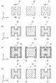
次に、本発明の実施形態に係る振動子1に用いられている振動片2の変形例について説明する。
図9は、本発明の実施形態に係る振動子に用いられている振動片の変形例を示す平面図であり、図9(a)は変形例1、図9(b)は変形例2、図9(c)は変形例3、図9(d)は変形例4である。
図10は、本発明の実施形態に係る振動子に用いられている振動片の変形例を示す平面図であり、図10(a)は変形例5、図10(b)は変形例6、図10(c)は変形例7、図10(d)は変形例8である。
以下、変形例について、前述した実施形態との相違点を中心に説明し、同様の構成には、同一符号を付してあり、同様の事項については、その説明を省略する。
(Modification example of vibrating piece)
Next, a modification of the
FIG. 9 is a plan view showing a modification of the resonator element used in the vibrator according to the embodiment of the present invention. FIG. 9A is a
FIG. 10 is a plan view showing a modification of the resonator element used in the vibrator according to the embodiment of the present invention. FIG. 10A is a modification 5, FIG. 10B is a modification 6, FIG. 10C shows a seventh modification, and FIG. 10D shows a eighth modification.
Hereinafter, the modified example will be described focusing on differences from the above-described embodiment, and the same components are denoted by the same reference numerals, and the description of the same matters is omitted.
図9(a)に示す変形例1の振動片2aは、基部12aの第2の端面7a側に−Y軸方向に向かって幅が漸減する縮幅部16aを有している。このような縮幅部16aを有することにより、第1、第2の振動腕21,22の屈曲振動による振動漏れを抑制することができ、高いQ値を有する振動片2aを得ることができる。
The
図9(b)に示す変形例2の振動片2bは、変形例1と同様に、基部12bの第2の端面7b側に−Y軸方向に向かって幅が漸減する円弧形の縮幅部16bを有し、第1、第2の振動腕21,22の屈曲振動による振動漏れを抑制しているので、高いQ値を有する振動片2bを得ることができる。
The
図9(c)に示す変形例3の振動片2cは、基部12cを支持する構造であり、第1、第2の振動腕21,22の間に支持腕がない構造なので、振動片2cの幅(X軸方向)寸法を小さくすることができ、幅の狭い小型の振動片2cを得ることができる。
The vibration piece 2c of
図9(d)に示す変形例4の振動片2dは、変形例3と同様に、第1、第2の振動腕21,22の間に支持腕がない構造なので、振動片2dの幅(X軸方向)寸法を小さくすることができる。また、基部12dの第1の端面6dに+Y軸方向に向かって幅が漸減する円弧形の縮幅部17dと、基部12dの第2の端面7dに−Y軸方向に向かって幅が漸減する円弧形の縮幅部16dと、を有しているので、第1、第2の振動腕21,22の屈曲振動による振動漏れをより抑制でき、高いQ値を有することができる。そのため、小型で高いQ値を有する振動片2dを得ることができる。
The
図10(a)に示す変形例5の振動片2eは、基部12eの第1の端面6e及び第2の端面7eに、+Y軸方向に向かって幅が漸減する円弧形の縮幅部17eと、−Y軸方向に向かって幅が漸減する円弧形の縮幅部16eと、第1、第2の振動腕21,22の間に支持腕23eと、を有しており、支持腕23eの先端部に支持部26eが設けられている。そのため、基部12eに円弧形の縮幅部16e,17eを有し、且つ基部12eから離れた位置にある支持部26eを支持・固定することができるので、第1、第2の振動腕21,22の屈曲振動による振動漏れをより抑制でき、高いQ値を有する動片2eを得ることができる。
A vibrating
図10(b)に示す変形例6の振動片2fは、支持部26fが第1、第2の振動腕21,22及び基部12fを囲む枠状に形成されている。そのため、支持部26fが蓋とパッケージベースとで狭持され、支持部26fが図示しないパッケージの一部を兼ねた、平面サイズが振動片2fと等しい振動子1を得ることができる。
In the vibrating
図10(c)に示す変形例7の振動片2gは、基部12gのX軸方向の両端に支持腕23gが設けられているため、2つの支持腕23gを支持・固定することができるため、耐振動強度や耐落下強度に優れた振動片2gを得ることができる。
Since the vibrating piece 2g of the modified example 7 shown in FIG. 10C is provided with the supporting
図10(d)に示す変形例8の振動片2hは、変形例6と同様に、支持部26hが第1、第2の振動腕21,22及び基部12hを囲む枠状に形成されている。そのため、支持部26hが蓋とパッケージベースとで狭持され、支持部26hが図示しないパッケージの一部を兼ねた、平面サイズが振動片2hと等しい振動子1を得ることができる。
In the vibrating
(電子デバイス)
次に、本発明の振動子1を適用した電子デバイス3について説明する。
図11は、本発明の電子デバイスの構造を示した概略図であり、図11(a)は平面図、図11(b)は図11(a)に示すD−D線断面図である。
電子デバイス3は、振動子1と、振動子1を駆動するための発振回路を有するICチップ(チップ部品)62と、振動子1やICチップ62を収納するパッケージ本体60と、ガラス、セラミック、金属等からなる蓋部材56と、で構成されている。
(Electronic device)
Next, an
11A and 11B are schematic views showing the structure of the electronic device of the present invention. FIG. 11A is a plan view, and FIG. 11B is a cross-sectional view taken along the line DD shown in FIG.
The
パッケージ本体60は、図11(b)に示すように、本実施形態の振動子1と同様に、第1の基板51、第2の基板52及び実装端子45を積層して形成されている。また、パッケージ本体60は、上面に開放するキャビティー72を有している。なお、振動子1とICチップ62とを収容するキャビティー72内は減圧雰囲気あるいは窒素などの不活性気体雰囲気に気密封止されている。
As shown in FIG. 11B, the package
実装端子45は、第1の基板51の外部底面に複数設けられている。また、実装端子45は、第1の基板51の上面に設けられた接続電極46や接続端子48と、図示しない貫通電極や層間配線を介して、電気的に導通されている。
A plurality of mounting
パッケージ本体60のキャビティー72内には、振動子1とICチップ62が収容されている。振動子1は、半田や導電性接着剤を介して第1の基板51の上面に設けられた接続電極46に固定されている。ICチップ62は、ろう材あるいは接着剤等の接合部材42を介して第1の基板51の上面に固定されている。また、キャビティー72には、複数の接続端子48が設けられている。接続端子48は、ボンディングワイヤー44によってICチップ62の上面に設けられた接続端子64と電気的に接続されている。
The
ICチップ62は、振動子1の駆動を制御するための駆動回路(発振回路)を有しており、このICチップ62によって振動子1を駆動すると、所定の周波数の信号を取り出すことができる。
The
(電子機器)
次いで、本発明の振動子1を適用した電子機器について、図12〜図14に基づき、詳細に説明する。
図12は、本発明の振動子を備える電子機器としてのモバイル型(又はノート型)のパーソナルコンピューターの構成を示す斜視図である。この図において、パーソナルコンピューター1100は、キーボード1102を備えた本体部1104と、表示部100を備えた表示ユニット1106とにより構成され、表示ユニット1106は、本体部1104に対しヒンジ構造部を介して回動可能に支持されている。このようなパーソナルコンピューター1100には、振動子1が内蔵されている。
(Electronics)
Next, an electronic device to which the
FIG. 12 is a perspective view illustrating a configuration of a mobile (or notebook) personal computer as an electronic apparatus including the vibrator of the present invention. In this figure, a
図13は、本発明の振動子を備える電子機器としての携帯電話機(PHSも含む)の構成を示す斜視図である。この図において、携帯電話機1200は、複数の操作ボタン1202、受話口1204及び送話口1206を備え、操作ボタン1202と受話口1204との間には、表示部100が配置されている。このような携帯電話機1200には、振動子1が内蔵されている。
FIG. 13 is a perspective view illustrating a configuration of a mobile phone (including PHS) as an electronic apparatus including the vibrator according to the invention. In this figure, a
図14は、本発明の振動子を備える電子機器としてのデジタルカメラの構成を示す斜視図である。なお、この図には、外部機器との接続についても簡易的に示されている。ここで、通常のカメラは、被写体の光像により銀塩写真フィルムを感光するのに対し、デジタルカメラ1300は、被写体の光像をCCD(Charge Coupled Device)等の撮像素子により光電変換して撮像信号(画像信号)を生成する。
FIG. 14 is a perspective view illustrating a configuration of a digital camera as an electronic apparatus including the vibrator according to the invention. In this figure, connection with an external device is also simply shown. Here, a normal camera sensitizes a silver salt photographic film with a light image of a subject, whereas a
デジタルカメラ1300におけるケース(ボディー)1302の背面には、表示部100が設けられ、CCDによる撮像信号に基づいて表示を行う構成になっており、表示部100は、被写体を電子画像として表示するファインダーとして機能する。また、ケース1302の正面側(図中裏面側)には、光学レンズ(撮像光学系)やCCD等を含む受光ユニット1304が設けられている。
A
撮影者が表示部100に表示された被写体像を確認し、シャッターボタン1306を押下すると、その時点におけるCCDの撮像信号が、メモリー1308に転送・格納される。また、このデジタルカメラ1300においては、ケース1302の側面に、ビデオ信号出力端子1312と、データ通信用の入出力端子1314とが設けられている。
When the photographer confirms the subject image displayed on the
そして、図示されるように、ビデオ信号出力端子1312にはテレビモニター1430が、データ通信用の入出力端子1314にはパーソナルコンピューター1440が、それぞれ必要に応じて接続される。更に、所定の操作により、メモリー1308に格納された撮像信号が、テレビモニター1430や、パーソナルコンピューター1440に出力される構成になっている。このようなデジタルカメラ1300には、振動子1が内蔵されている。
As shown in the figure, a
なお、本発明の振動子1を備える電子機器は、図12のパーソナルコンピューター(モバイル型パーソナルコンピューター)、図13の携帯電話機、図14のデジタルカメラの他にも、例えば、インクジェット式吐出装置(例えばインクジェットプリンター)、ラップトップ型パーソナルコンピューター、テレビ、ビデオカメラ、ビデオテープレコーダー、カーナビゲーション装置、ページャー、電子手帳(通信機能付も含む)、電子辞書、電卓、電子ゲーム機器、ワードプロセッサー、ワークステーション、テレビ電話、防犯用テレビモニター、電子双眼鏡、POS端末、医療機器(例えば電子体温計、血圧計、血糖計、心電図計測装置、超音波診断装置、電子内視鏡)、魚群探知機、各種測定機器、計器類(例えば、車両、航空機、船舶の計器類)、フライトシミュレーター等に適用することができる。
The electronic device including the
(移動体)
次に、本発明の振動子1を適用した移動体について説明する。
図15は、本発明の移動体の一例としての自動車を概略的に示す斜視図である。自動車1500には、振動子1が搭載されている。振動子1は、キーレスエントリー、イモビライザー、ナビゲーションシステム、エアコン、アンチロックブレーキシステム(ABS:Antilock Brake System)、エアバック、タイヤプレッシャーモニタリングシステム(TPMS:Tire Pressure Monitoring System)、エンジンコントロール、ハイブリッド自動車や電気自動車の電池モニター、車体姿勢制御システム等の電子制御ユニット(ECU:electronic control unit)1510に広く適用できる。
(Moving body)
Next, a moving body to which the
FIG. 15 is a perspective view schematically showing an automobile as an example of the moving object of the present invention. A
以上、本発明の振動子1、振動片2、電子デバイス3、電子機器及び移動体について、図示の実施形態に基づいて説明したが、本発明は、これに限定されるものではなく、各部の構成は、同様の機能を有する任意の構成のものに置換することができる。また、本発明に、他の任意の構成物が付加されていてもよい。また、各実施形態を適宜組み合わせてもよい。
As mentioned above, although the vibrator |
1…振動子、2…振動片、3…電子デバイス、6…第1の端面、7…第2の端面、10…振動基板、12…基部、18,19…くびれ部、21…第1の振動腕、22…第2の振動腕、23…支持腕、24,25…錘部、28a,28b,29a,29b…溝、30…電極、30a…電極膜、31…第1駆動用電極、32…第2駆動用電極、33a,33b,34a,34b…側面、35a,35b,35c,35d,35e,35f,36a,36b,36c,36d,36e,36f…配線、37…第1導電パッド、38…第2導電パッド、40…レジスト膜、42…接合部材、44…ボンディングワイヤー、45…実装端子、46,47…接続電極、48…接続端子、50…パッケージ本体、51…第1の基板、52…第2の基板、56…蓋部材、58…封止材、60…パッケージ本体、62…ICチップ、64…接続端子、70,72…キャビティー、100…表示部、1100…パーソナルコンピューター、1102…キーボード、1104…本体部、1106…表示ユニット、1200…携帯電話機、1202…操作ボタン、1204…受話口、1206…送話口、1300…デジタルカメラ、1302…ケース、1304…受光ユニット、1306…シャッターボタン、1308…メモリー、1312…ビデオ信号出力端子、1314…入出力端子、1430…テレビモニター、1440…パーソナルコンピューター、1500…自動車、1510…電子制御ユニット。
DESCRIPTION OF
Claims (11)
前記基部の前記第1の端面側から第1方向に延出し、前記第1方向と直交する第2方向に離間して配置されている一対の振動腕と、
を含む振動片であって、
前記第1の端面と前記第2の端面との最短距離をWbとしたとき、
Q={(ρ・Cp)/(c・α2・Θ)}
×[{1+(2・ρ・Cp・We2・f/(π・k))2}
/(2・ρ・Cp・We2・f/(π・k))]
0.81≦Wb/We≦1.70
の関係を満足することを特徴とする振動片。
但し、Qは前記振動片のQ値、fは前記振動片の振動周波数[Hz]、Weは実効幅[m]、ρは質量密度[kg/m3]、Cpは熱容量[J/(kg・K)]、cは前記Wbの方向と面内で直交する方向に関する弾性定数[N/m2]、αは前記Wbの方向と面内で直交する方向に関する熱膨張係数[1/K]、Θは環境温度[K]、kは前記Wbの方向に関する熱伝導率[W/(m・K)] A base having a second end surface of the back side of the first end surface and said first end surface,
Extending in a first direction from the first end face side front Symbol of the base portion, and a pair of vibrating arms that are spaced apart in a second direction perpendicular to said first direction,
A vibrating piece including
When the shortest distance between the first end surface and the second end surface is Wb ,
Q = {(ρ · C p ) / (c · α 2 · Θ)}
× [{1+ (2 · ρ · C p · We 2 · f / ( π · k ) ) 2 }
/ (2 · ρ · C p · We 2 · f / ( π · k ) ) ]]
0 . 81 ≦ Wb / We ≦ 1.7 0
A vibrating piece characterized by satisfying the relationship of
Where Q is the Q value of the resonator element , f is the vibration frequency [Hz] of the resonator element, We is the effective width [m], ρ is the mass density [kg / m 3 ], and C p is the heat capacity [J / ( kg · K)], c is the elastic constant [N / m 2 ] in the direction orthogonal to the direction of Wb in the plane, and α is the thermal expansion coefficient [1 / K in the direction orthogonal to the direction of Wb in the plane. ], Θ is the environmental temperature [K], k is the thermal conductivity [W / (m · K ) ] in the direction of Wb.
0.91≦Wb/We≦1.30、
の関係を満足することを特徴とする振動片。 In claim 1,
0.91 ≦ Wb / We ≦ 1.30,
A vibrating piece characterized by satisfying the relationship of
1.00≦Wb/We≦1.20、
の関係を満足することを特徴とする振動片。 In claim 1 or 2,
1.00 ≦ Wb / We ≦ 1.20,
A vibrating piece characterized by satisfying the relationship of
前記基部から支持腕が延出していることを特徴とする振動片。 And have you to any one of claims 1 to 3,
A vibrating piece, wherein a support arm extends from the base.
前記支持腕は、
前記一対の振動腕の間に配置されていることを特徴とする振動片。 In claim 4,
The support arm is
Resonator element, characterized in that it is placed between the pair of vibrating arms.
2つの前記支持腕を有し、
平面視で、前記2つの支持腕の間に前記一対の振動腕が配置されていることを特徴とする振動片。 In claim 4,
Having two said support arms,
The resonator element, wherein the pair of vibrating arms is disposed between the two support arms in a plan view .
内部に前記振動片が収納されている容器と、
を備えていることを特徴とする振動子。 The resonator element according to claim 1,
A container in which the resonator element therein is housed,
A vibrator characterized by comprising:
前記容器の前記内部が真空であることを特徴とする振動子。 In claim 7,
Vibrator, wherein the interior of said container is a vacuum.
回路と、
を備えていることを特徴とする電子デバイス。 The resonator element according to claim 1,
Circuit,
An electronic device comprising:
Priority Applications (5)
| Application Number | Priority Date | Filing Date | Title |
|---|---|---|---|
| JP2013131936A JP6155897B2 (en) | 2013-06-24 | 2013-06-24 | Vibrating piece, vibrator, electronic device, electronic device, and moving object |
| CN201410286254.4A CN104242860B (en) | 2013-06-24 | 2014-06-24 | Vibrating reed, oscillator, electronic device, electronic equipment and moving body |
| US14/313,468 US9705472B2 (en) | 2013-06-24 | 2014-06-24 | Resonator element, resonator, electronic device, electronic apparatus, and moving object |
| CN201811050020.4A CN109217838B (en) | 2013-06-24 | 2014-06-24 | Resonator element, resonator, electronic device, electronic apparatus, and moving object |
| US15/615,418 US10659006B2 (en) | 2013-06-24 | 2017-06-06 | Resonator element, resonator, electronic device, electronic apparatus, and moving object |
Applications Claiming Priority (1)
| Application Number | Priority Date | Filing Date | Title |
|---|---|---|---|
| JP2013131936A JP6155897B2 (en) | 2013-06-24 | 2013-06-24 | Vibrating piece, vibrator, electronic device, electronic device, and moving object |
Related Child Applications (1)
| Application Number | Title | Priority Date | Filing Date |
|---|---|---|---|
| JP2017101491A Division JP6465152B2 (en) | 2017-05-23 | 2017-05-23 | Vibrating piece, vibrator, electronic device, electronic device, and moving object |
Publications (3)
| Publication Number | Publication Date |
|---|---|
| JP2015008352A JP2015008352A (en) | 2015-01-15 |
| JP2015008352A5 JP2015008352A5 (en) | 2016-07-14 |
| JP6155897B2 true JP6155897B2 (en) | 2017-07-05 |
Family
ID=52110320
Family Applications (1)
| Application Number | Title | Priority Date | Filing Date |
|---|---|---|---|
| JP2013131936A Expired - Fee Related JP6155897B2 (en) | 2013-06-24 | 2013-06-24 | Vibrating piece, vibrator, electronic device, electronic device, and moving object |
Country Status (3)
| Country | Link |
|---|---|
| US (2) | US9705472B2 (en) |
| JP (1) | JP6155897B2 (en) |
| CN (2) | CN104242860B (en) |
Families Citing this family (6)
| Publication number | Priority date | Publication date | Assignee | Title |
|---|---|---|---|---|
| JP6182998B2 (en) * | 2013-06-24 | 2017-08-23 | セイコーエプソン株式会社 | Quartz crystal resonator element, vibrator, electronic device, electronic equipment, and moving object |
| TWI634742B (en) * | 2013-11-16 | 2018-09-01 | 精工愛普生股份有限公司 | Resonator blank, resonator, oscillator, electronic apparatus, and mobile object |
| JP6536783B2 (en) * | 2015-02-09 | 2019-07-03 | セイコーエプソン株式会社 | Vibrating piece, vibrator, oscillator, real time clock, electronic device, and moving body |
| JP6488861B2 (en) * | 2015-04-28 | 2019-03-27 | セイコーエプソン株式会社 | Vibrating piece, vibrator, oscillator, real-time clock, sensor, electronic device and moving object |
| WO2018163842A1 (en) * | 2017-03-09 | 2018-09-13 | 株式会社村田製作所 | Elastic wave device, high-frequency front end circuit, and communications device |
| JP2018160802A (en) * | 2017-03-23 | 2018-10-11 | セイコーエプソン株式会社 | Vibration element, electronic device, electronic apparatus, and mobile body |
Family Cites Families (53)
| Publication number | Priority date | Publication date | Assignee | Title |
|---|---|---|---|---|
| JPH0894362A (en) * | 1994-09-20 | 1996-04-12 | Yoshiro Tomikawa | Oscillatory gyroscope |
| JP2002141770A (en) | 2000-11-01 | 2002-05-17 | Citizen Watch Co Ltd | Small-sized vibrator |
| JP4068370B2 (en) * | 2001-09-07 | 2008-03-26 | シチズンホールディングス株式会社 | Vibrating gyro |
| TW567664B (en) | 2001-10-09 | 2003-12-21 | Ebauchesfabrik Eta Ag | Piezoelectric resonator and assembly comprising the same enclosed in a case |
| US8358052B2 (en) * | 2003-06-30 | 2013-01-22 | Piedek Technical Laboratory | Unit having resonator, oscillator having unit and electronic apparatus having unit |
| JP2010119128A (en) | 2003-08-19 | 2010-05-27 | Seiko Epson Corp | Tuning-fork type piezoelectric vibrator piece |
| JP3951058B2 (en) | 2003-08-19 | 2007-08-01 | セイコーエプソン株式会社 | Tuning fork type piezoelectric vibrating piece |
| EP1732219B1 (en) * | 2005-06-09 | 2008-03-26 | ETA SA Manufacture Horlogère Suisse | Piezoelectric resonator and assembly comprising the same enclosed in a case |
| EP1732220B1 (en) | 2005-06-09 | 2008-03-26 | ETA SA Manufacture Horlogère Suisse | Small-sized piezoelectric resonator |
| DE602005012488D1 (en) | 2005-06-09 | 2009-03-12 | Eta Sa Mft Horlogere Suisse | Compact piezoelectric resonator |
| WO2008018222A1 (en) * | 2006-08-10 | 2008-02-14 | Daishinku Corporation | Piezoelectric vibration device |
| JP5115092B2 (en) * | 2006-08-18 | 2013-01-09 | セイコーエプソン株式会社 | Piezoelectric vibrating piece, piezoelectric device, and oscillator |
| JP4933903B2 (en) | 2007-01-17 | 2012-05-16 | リバーエレテック株式会社 | Quartz vibrator, quartz vibrator and quartz wafer |
| EP2071721B1 (en) | 2007-12-13 | 2011-02-23 | ETA SA Manufacture Horlogère Suisse | Piezoelectric resonator in a small-sized package |
| JP2009164775A (en) | 2007-12-28 | 2009-07-23 | Nippon Dempa Kogyo Co Ltd | Piezoelectric frame and piezoelectric device |
| WO2009116523A1 (en) | 2008-03-18 | 2009-09-24 | シチズンホールディングス株式会社 | Piezoelectric device |
| JP4709260B2 (en) * | 2008-10-16 | 2011-06-22 | 日本電波工業株式会社 | Piezoelectric vibrating piece and piezoelectric device |
| JP4885206B2 (en) * | 2008-12-22 | 2012-02-29 | 日本電波工業株式会社 | Tuning fork type piezoelectric vibrating piece and piezoelectric device |
| JP5454134B2 (en) | 2008-12-27 | 2014-03-26 | セイコーエプソン株式会社 | Vibrating piece, vibrator, sensor and electronic component |
| JP2010157933A (en) | 2008-12-27 | 2010-07-15 | Epson Toyocom Corp | Bending vibrating piece and electronic component |
| US8067880B2 (en) | 2008-12-27 | 2011-11-29 | Seiko Epson Corporation | Flexural vibration element and electronic component |
| JP5218104B2 (en) | 2009-01-29 | 2013-06-26 | 株式会社大真空 | Tuning fork type piezoelectric vibrating piece and tuning fork type piezoelectric vibrating device |
| JP2010183138A (en) | 2009-02-03 | 2010-08-19 | Seiko Epson Corp | Method of manufacturing tuning fork crystal oscillator |
| JP2010226608A (en) | 2009-03-25 | 2010-10-07 | Seiko Epson Corp | Bent vibrating piece and oscillator employing the same |
| JP2010252303A (en) * | 2009-03-25 | 2010-11-04 | Seiko Epson Corp | Bending vibrator piece and oscillator using the same |
| JP2010252302A (en) | 2009-03-25 | 2010-11-04 | Seiko Epson Corp | Bending vibrator piece and oscillator using the same |
| JP2010226610A (en) | 2009-03-25 | 2010-10-07 | Seiko Epson Corp | Bent vibrating piece and oscillator employing the same |
| JP5399767B2 (en) * | 2009-04-28 | 2014-01-29 | 京セラクリスタルデバイス株式会社 | Crystal oscillator |
| JP5272880B2 (en) * | 2009-04-30 | 2013-08-28 | セイコーエプソン株式会社 | Bending vibration piece |
| JP5302776B2 (en) | 2009-05-29 | 2013-10-02 | 京セラクリスタルデバイス株式会社 | Crystal piece assembly board |
| JP5350102B2 (en) | 2009-06-30 | 2013-11-27 | 京セラクリスタルデバイス株式会社 | Tuning fork type bending crystal unit |
| JP5341647B2 (en) | 2009-07-10 | 2013-11-13 | リバーエレテック株式会社 | Piezoelectric vibrating piece, piezoelectric vibrator and piezoelectric oscillator |
| JP5565154B2 (en) * | 2009-09-11 | 2014-08-06 | セイコーエプソン株式会社 | Vibrating piece, vibrator, oscillator, and electronic device |
| JP5482541B2 (en) * | 2009-10-01 | 2014-05-07 | セイコーエプソン株式会社 | Vibrating piece, vibrator, oscillator, and electronic device |
| JP5593979B2 (en) | 2009-11-11 | 2014-09-24 | セイコーエプソン株式会社 | Vibrating piece, vibrator, oscillator, sensor and electronic equipment |
| JP2011155629A (en) * | 2009-12-29 | 2011-08-11 | Seiko Epson Corp | Vibrating reed, vibrator, oscillator, electronic device, and frequency adjustment method |
| JP2011193436A (en) | 2010-02-18 | 2011-09-29 | Daishinku Corp | Tuning fork crystal resonator chip, tuning fork crystal resonator, and method of manufacturing the tuning fork crystal resonator chip |
| US8692632B2 (en) | 2010-03-17 | 2014-04-08 | Seiko Epson Corporation | Resonator element, resonator, oscillator, and electronic device |
| JP5504999B2 (en) | 2010-03-17 | 2014-05-28 | セイコーエプソン株式会社 | Vibrating piece, vibrator, oscillator |
| JP2011259120A (en) * | 2010-06-08 | 2011-12-22 | Seiko Epson Corp | Vibration piece, frequency adjusting method, vibrator, vibration device, and electronic apparatus |
| JP2012147329A (en) | 2011-01-13 | 2012-08-02 | Citizen Finetech Miyota Co Ltd | Tuning-fork type crystal vibrating piece |
| TW201242246A (en) * | 2011-02-25 | 2012-10-16 | Seiko Epson Corp | Piezoelectric vibration element, piezoelectric vibrator, piezoelectric oscillator, vibration gyro element, vibration gyro sensor, and electronic apparatus |
| JP2012186679A (en) | 2011-03-07 | 2012-09-27 | Seiko Epson Corp | Piezoelectric vibration element, piezoelectric vibrator, piezoelectric oscillator, and electronic device |
| JP5708089B2 (en) * | 2011-03-18 | 2015-04-30 | セイコーエプソン株式会社 | Piezoelectric vibration element, piezoelectric vibrator, piezoelectric oscillator, and electronic device |
| JP2012227961A (en) | 2012-07-27 | 2012-11-15 | Citizen Holdings Co Ltd | Oscillator |
| JP6127495B2 (en) | 2012-12-19 | 2017-05-17 | セイコーエプソン株式会社 | Vibrating piece, vibrator, oscillator, electronic device, moving body, and method of manufacturing vibrating piece |
| JP6349622B2 (en) * | 2013-03-14 | 2018-07-04 | セイコーエプソン株式会社 | Vibration element, vibrator, oscillator, electronic device, and moving object |
| JP2015008353A (en) * | 2013-06-24 | 2015-01-15 | セイコーエプソン株式会社 | Vibration element, vibration device, electronic apparatus, moving body, and method of manufacturing vibration element |
| JP2015023422A (en) * | 2013-07-18 | 2015-02-02 | セイコーエプソン株式会社 | Vibration piece, vibrator, oscillator, electronic apparatus and mobile |
| DE102014109746B4 (en) * | 2014-07-11 | 2020-10-29 | Infineon Technologies Ag | Methods and devices for storing parameters |
| KR20160076711A (en) * | 2014-12-23 | 2016-07-01 | 삼성전기주식회사 | Tuning Fork Type Vibrator |
| JP2017200015A (en) * | 2016-04-26 | 2017-11-02 | セイコーエプソン株式会社 | Vibrator, oscillator, electronic apparatus, and movable body |
| JP2018046471A (en) * | 2016-09-16 | 2018-03-22 | 日本電波工業株式会社 | Tuning-fork type crystal vibrator |
-
2013
- 2013-06-24 JP JP2013131936A patent/JP6155897B2/en not_active Expired - Fee Related
-
2014
- 2014-06-24 US US14/313,468 patent/US9705472B2/en active Active
- 2014-06-24 CN CN201410286254.4A patent/CN104242860B/en active Active
- 2014-06-24 CN CN201811050020.4A patent/CN109217838B/en active Active
-
2017
- 2017-06-06 US US15/615,418 patent/US10659006B2/en active Active
Also Published As
| Publication number | Publication date |
|---|---|
| CN104242860A (en) | 2014-12-24 |
| CN109217838B (en) | 2021-12-24 |
| US9705472B2 (en) | 2017-07-11 |
| CN109217838A (en) | 2019-01-15 |
| US20140375177A1 (en) | 2014-12-25 |
| US10659006B2 (en) | 2020-05-19 |
| US20170272054A1 (en) | 2017-09-21 |
| JP2015008352A (en) | 2015-01-15 |
| CN104242860B (en) | 2018-10-02 |
Similar Documents
| Publication | Publication Date | Title |
|---|---|---|
| US10659006B2 (en) | Resonator element, resonator, electronic device, electronic apparatus, and moving object | |
| TWI634742B (en) | Resonator blank, resonator, oscillator, electronic apparatus, and mobile object | |
| JP2012065293A (en) | Vibration piece, manufacturing method of vibration piece, vibrator, vibration device and electronic apparatus | |
| TWI604693B (en) | Vibrating element, vibrator, oscillator, electronic apparatus, and moving object | |
| CN105987690B (en) | Resonator element, resonator device, oscillator, electronic apparatus, and moving object | |
| KR20140118840A (en) | Vibrating element, vibrator, oscillator, electronic apparatus, and moving object | |
| TWI649964B (en) | Vibrating element, vibrator, oscillator, electronic device, and moving object | |
| CN108183698A (en) | Vibrating elements, oscillator, oscillator, electronic equipment, sensor and moving body | |
| US9354128B2 (en) | Resonator element, resonator, oscillator, electronic apparatus, sensor, and mobile object | |
| US20150137900A1 (en) | Resonator element, resonator, oscillator, electronic device, and mobile object | |
| JP2015008351A (en) | Vibration piece, vibrator, electronic device, electronic apparatus and mobile | |
| TW201526542A (en) | Vibration element, vibrator, oscillator, electronic apparatus, and moving object | |
| JP6287208B2 (en) | Vibrators, oscillators, electronic devices, physical quantity sensors, and moving objects | |
| US10305426B2 (en) | Method for manufacturing resonator element, wafer, resonator element, resonator, oscillator, real-time clock, electronic apparatus, and moving object | |
| JP2014200050A (en) | Vibration element, vibrator, oscillator, electronic device, and mobile unit | |
| US9287848B2 (en) | Resonator element, resonator, oscillator, electronic apparatus, and moving object having reduced vibration leakage | |
| JP6465152B2 (en) | Vibrating piece, vibrator, electronic device, electronic device, and moving object | |
| JP2014200039A (en) | Vibration piece, vibrator, oscillator, electronic apparatus and moving body | |
| JP2015002556A (en) | Vibration piece, vibrator, oscillator, electronic device, and mobile unit | |
| JP2014200052A (en) | Vibration piece, vibrator, oscillator, electronic apparatus and moving body | |
| JP6816805B2 (en) | Vibrating elements, oscillators, oscillators, electronic devices and mobiles | |
| JP6680372B2 (en) | Vibrators, vibrating devices, oscillators, electronics, and mobiles | |
| JP2014179914A (en) | Vibrator, oscillator, electronic apparatus and mobile | |
| JP2014107712A (en) | Vibration reed, vibrator, oscillator, electronic equipment and mobile unit | |
| JP6543889B2 (en) | Electronic device, electronic device and mobile |
Legal Events
| Date | Code | Title | Description |
|---|---|---|---|
| RD04 | Notification of resignation of power of attorney |
Free format text: JAPANESE INTERMEDIATE CODE: A7424 Effective date: 20150113 |
|
| A521 | Written amendment |
Free format text: JAPANESE INTERMEDIATE CODE: A523 Effective date: 20160525 |
|
| A621 | Written request for application examination |
Free format text: JAPANESE INTERMEDIATE CODE: A621 Effective date: 20160525 |
|
| RD04 | Notification of resignation of power of attorney |
Free format text: JAPANESE INTERMEDIATE CODE: A7424 Effective date: 20160617 |
|
| RD03 | Notification of appointment of power of attorney |
Free format text: JAPANESE INTERMEDIATE CODE: A7423 Effective date: 20160624 |
|
| A977 | Report on retrieval |
Free format text: JAPANESE INTERMEDIATE CODE: A971007 Effective date: 20170426 |
|
| TRDD | Decision of grant or rejection written | ||
| A01 | Written decision to grant a patent or to grant a registration (utility model) |
Free format text: JAPANESE INTERMEDIATE CODE: A01 Effective date: 20170509 |
|
| A61 | First payment of annual fees (during grant procedure) |
Free format text: JAPANESE INTERMEDIATE CODE: A61 Effective date: 20170522 |
|
| R150 | Certificate of patent or registration of utility model |
Ref document number: 6155897 Country of ref document: JP Free format text: JAPANESE INTERMEDIATE CODE: R150 |
|
| LAPS | Cancellation because of no payment of annual fees |