JP5272880B2 - Bending vibration piece - Google Patents
Bending vibration piece Download PDFInfo
- Publication number
- JP5272880B2 JP5272880B2 JP2009111256A JP2009111256A JP5272880B2 JP 5272880 B2 JP5272880 B2 JP 5272880B2 JP 2009111256 A JP2009111256 A JP 2009111256A JP 2009111256 A JP2009111256 A JP 2009111256A JP 5272880 B2 JP5272880 B2 JP 5272880B2
- Authority
- JP
- Japan
- Prior art keywords
- vibrating arm
- groove portions
- vibrating
- groove
- base
- Prior art date
- Legal status (The legal status is an assumption and is not a legal conclusion. Google has not performed a legal analysis and makes no representation as to the accuracy of the status listed.)
- Expired - Fee Related
Links
- 238000005452 bending Methods 0.000 title claims description 46
- 230000005284 excitation Effects 0.000 claims description 20
- 238000006073 displacement reaction Methods 0.000 description 16
- 239000013078 crystal Substances 0.000 description 7
- 239000010453 quartz Substances 0.000 description 5
- VYPSYNLAJGMNEJ-UHFFFAOYSA-N silicon dioxide Inorganic materials O=[Si]=O VYPSYNLAJGMNEJ-UHFFFAOYSA-N 0.000 description 5
- 230000000694 effects Effects 0.000 description 4
- 239000000463 material Substances 0.000 description 4
- 238000012986 modification Methods 0.000 description 3
- 230000004048 modification Effects 0.000 description 3
- 230000003287 optical effect Effects 0.000 description 3
- 230000005684 electric field Effects 0.000 description 2
- 239000004065 semiconductor Substances 0.000 description 2
- 229910052710 silicon Inorganic materials 0.000 description 2
- 239000010703 silicon Substances 0.000 description 2
- 230000006835 compression Effects 0.000 description 1
- 238000007906 compression Methods 0.000 description 1
- 239000000470 constituent Substances 0.000 description 1
- 230000000116 mitigating effect Effects 0.000 description 1
Images


Classifications
-
- H—ELECTRICITY
- H03—ELECTRONIC CIRCUITRY
- H03H—IMPEDANCE NETWORKS, e.g. RESONANT CIRCUITS; RESONATORS
- H03H9/00—Networks comprising electromechanical or electro-acoustic devices; Electromechanical resonators
- H03H9/15—Constructional features of resonators consisting of piezoelectric or electrostrictive material
- H03H9/21—Crystal tuning forks
- H03H9/215—Crystal tuning forks consisting of quartz
-
- H—ELECTRICITY
- H03—ELECTRONIC CIRCUITRY
- H03H—IMPEDANCE NETWORKS, e.g. RESONANT CIRCUITS; RESONATORS
- H03H9/00—Networks comprising electromechanical or electro-acoustic devices; Electromechanical resonators
- H03H9/15—Constructional features of resonators consisting of piezoelectric or electrostrictive material
- H03H9/17—Constructional features of resonators consisting of piezoelectric or electrostrictive material having a single resonator
- H03H9/19—Constructional features of resonators consisting of piezoelectric or electrostrictive material having a single resonator consisting of quartz
Description
本発明は、例えば振動子や共振子、発振器、ジャイロ、各種センサ等の様々な圧電デバイス、その他の電子デバイスに使用され、屈曲振動モードで振動する屈曲振動片に関する。 The present invention relates to a bending vibration piece that is used in various piezoelectric devices such as vibrators, resonators, oscillators, gyros, various sensors, and other electronic devices and vibrates in a bending vibration mode.
従来、音叉型圧電振動片のような屈曲振動モードの圧電振動片では、振動腕の表面及び/又は裏面に長手方向の溝部を形成し、かつ該溝部の内面に励振電極を成膜した構造が広く採用されている(例えば、特許文献1を参照)。このような振動腕は、その側面の励振電極と溝部内の励振電極との間で電界が、振動腕の断面において広く分布するように発生し、電界効率が大幅に向上するので、振動片を小型化しても振動損失が少なく、CI値を低く抑制することができる。 Conventionally, a flexural vibration mode piezoelectric vibrating piece such as a tuning fork type piezoelectric vibrating piece has a structure in which a longitudinal groove is formed on the front and / or back of a vibrating arm, and an excitation electrode is formed on the inner surface of the groove. Widely employed (see, for example, Patent Document 1). Such a vibrating arm is generated so that the electric field is widely distributed in the cross section of the vibrating arm between the excitation electrode on the side surface and the excitation electrode in the groove, and the electric field efficiency is greatly improved. Even if the size is reduced, vibration loss is small and the CI value can be suppressed low.
また、屈曲振動モードの圧電振動片は、振動腕を屈曲励振させたときに振動エネルギーの損失が生じると、CI値の増加やQ値の低下などの性能低下を招くことになる。かかる振動エネルギーの損失を防止又は低減するために、振動腕が延出する基部の両側部に切込み部又は所定深さの切込み溝を形成した音叉型水晶振動片が知られている(特許文献2,3を参照)。振動腕の振動がその主面に対して垂直方向即ち面外方向の成分を含む場合、基部の切込み部又は切込み溝が、基部から漏れる振動を緩和することにより振動エネルギーの閉込効果を高め、CI値の増大を抑制しかつ振動片間でのCI値のばらつきを防止する。 In addition, if a vibration energy loss occurs when the vibrating arm is bent and excited, the piezoelectric vibrating piece in the bending vibration mode causes a decrease in performance such as an increase in CI value and a decrease in Q value. In order to prevent or reduce such loss of vibration energy, a tuning-fork type crystal vibrating piece is known in which cut portions or cut grooves having a predetermined depth are formed on both sides of a base portion from which a vibrating arm extends (Patent Document 2). , 3). When the vibration of the vibrating arm includes a component in a direction perpendicular to the main surface, that is, an out-of-plane direction, the base incision or incision groove enhances the effect of confining vibration energy by mitigating vibration leaking from the base, The increase in the CI value is suppressed and the variation in the CI value between the vibrating pieces is prevented.
振動エネルギーの損失は、屈曲振動する振動腕の圧縮部と引張応力を受ける伸張部との間で発生する温度差による熱伝導によっても発生する。この熱伝導によって生じるQ値の低下は熱弾性損失効果と呼ばれ、このQ値低下を防止又は抑制するために、矩形断面を有する振動腕(振動梁)の中心線上に溝又は孔を形成して熱伝導を阻止した音叉型の振動子が知られている(例えば、特許文献4を参照)。 The loss of vibration energy also occurs due to heat conduction due to a temperature difference generated between the compression part of the vibrating arm that undergoes bending vibration and the extension part that receives tensile stress. The decrease in the Q value caused by this heat conduction is called the thermoelastic loss effect. In order to prevent or suppress this Q value decrease, a groove or hole is formed on the center line of the vibrating arm (vibrating beam) having a rectangular cross section. A tuning fork type vibrator that prevents heat conduction is known (see, for example, Patent Document 4).
しかしながら、特許文献4記載のように振動腕に貫通孔を形成すると、その剛性が著しく低下するので、好ましくない。また、上記従来技術のように振動腕の表裏主面にその中心線上に溝部を形成した圧電振動片では、熱弾性効果に起因するQ値の低下を十分に防止又は抑制することが困難であった。
However, if the through-hole is formed in the vibrating arm as described in
そこで、本願発明者らは、基部から延長して屈曲振動する断面矩形の屈曲振動部即ち振動腕が、互いに対向しかつ屈曲振動により交互に伸縮する第1面及び第2面と、互いに対向しかつそれぞれ溝部を設けた第3面及び第4面とを有する屈曲振動片において、第3面と第4面間の距離よりも各溝部の深さを小さくしかつ両溝部の深さの和を大きくすると共に、両溝部を第1面と第2面間に配置した構成を提案している。このように溝部を設けて振動腕の断面をS字形状に形成することにより、第1面と第2面間の熱移動経路をより長くし、振動腕の伸張部と圧縮部間に発生する温度差が熱伝導で緩和するまでの時間をより長くして、熱弾性効果によるQ値変動の抑制を図っている。 Accordingly, the inventors of the present application have a bending vibration portion, that is, a vibrating arm having a rectangular section extending from the base portion and bending-vibrating, opposed to each other and the first surface and the second surface that are alternately expanded and contracted by bending vibration. In addition, in the bending vibration piece having the third surface and the fourth surface each provided with a groove portion, the depth of each groove portion is made smaller than the distance between the third surface and the fourth surface, and the sum of the depths of both groove portions is set. While enlarging, the structure which has arrange | positioned both groove parts between the 1st surface and the 2nd surface is proposed. Thus, by providing the groove portion and forming the cross section of the vibrating arm in an S shape, the heat transfer path between the first surface and the second surface is made longer, and the vibration arm is generated between the extending portion and the compressing portion. The time until the temperature difference is relaxed by heat conduction is lengthened to suppress the Q value fluctuation due to the thermoelastic effect.
ところが、このように溝部を形成した断面S字状の振動腕は、これを屈曲振動させたとき、溝部を形成した主面を含む面内方向だけでなく、該主面に対して垂直方向にも変位する場合があることが分かった。図9及び図10は、かかる断面S字状の振動腕を備える音叉型圧電振動片の構成を模式的に示している。 However, the vibration arm having the S-shaped cross section in which the groove portion is formed in this way is not only in the in-plane direction including the main surface on which the groove portion is formed, but also in the direction perpendicular to the main surface when the vibration arm is bent and vibrated. It has also been found that there is a case where it is displaced. 9 and 10 schematically show the configuration of a tuning-fork type piezoelectric vibrating piece having such a S-shaped vibrating arm.
図9(A)の音叉型圧電振動片1は、基部2から平行に延長する1対の振動腕3,4を有し、前記各振動腕の表裏主面には、それぞれ前記基部との結合部から長手方向に延長する1本の第1溝部5a,6a及び第2溝部5b,6bが同じ幅、長さ及び深さで形成されている。この従来例の圧電振動片1は、水晶で一体に形成され、水晶結晶軸の電気軸X軸を前記振動腕の幅方向に、機械軸Y軸を前記振動腕の長手方向に、光学軸Z軸を前記振動片の厚さ方向に配向している。
The tuning fork type piezoelectric vibrating
表側主面の第1溝部5a,6aは、各振動腕3,4の中心線iに関して幅方向の外側即ち他方の振動腕とは反対側に配置されている。裏側主面の第2溝部5b,6bは、前記各振動腕の長手方向の中心線iに関して幅方向の内側即ち他方の振動腕側に配置されている。第1溝部5a,6a及び第2溝部5b,6bは、図9(B)に示すように、深さが振動腕3,4の厚さの1/2より大きく、前記各振動腕の表裏主面から見て互いに重複せずかつ側面から見て互いに重複するように設けられている。その結果、前記各振動腕の断面は、両振動腕間の中心線i’に関して互いに線対称のS字形状に形成されている。
The first groove portions 5a and 6a on the front side main surface are arranged on the outer side in the width direction with respect to the center line i of the vibrating
振動腕3,4の前記第1溝部及び第2溝部には、それぞれ内面に第1励振電極(図示せず)が形成され、かつ前記各振動腕の両側面には、それぞれ第2励振電極(図示せず)が形成されている。一方の振動腕の第1励振電極と他方の振動腕の第2励振電極とが互いに接続され、それらに交流電圧を印加することによって、前記両振動腕が互いに接近又は離反する向きに振動する。
A first excitation electrode (not shown) is formed on the inner surface of each of the first and second groove portions of the vibrating
このとき、振動腕3,4は、前記表裏主面の面内方向だけでなく、面外方向即ち±Z方向にも振動成分を有することが分かった。前記各振動腕は、互いに離反する向きに屈曲するとき、図9(B)に矢印A1,A2で示すように、それぞれ−Z方向にも変位する。また、前記各振動腕は、互いに接近する向きに屈曲するとき、図9(B)に矢印B1,B2で示すように、それぞれ+Z方向にも変位する。
At this time, it was found that the vibrating
図10(A)の音叉型圧電振動片7は、表側主面の第1溝部8a,9aが、各振動腕3,4の中心線iに関して幅方向の同じ側に即ち図中左側に配置されている。裏側主面の第2溝部8b,9bも、前記各振動腕の中心線iに関して幅方向の同じ側に即ち図中右側に配置されている。前記第1溝部及び第2溝部の深さは、図9の圧電振動片1と同様に、振動腕3,4の厚さの1/2より大きく、前記各振動腕の表裏主面から見て互いに重複せずかつ側面から見て互いに重複するように設けられている。従って、図10(B)に示すように、圧電振動片7の前記各振動腕の断面は、両振動腕間の中心点Oに関して互いに点対称のS字形に形成されている。
In the tuning fork type piezoelectric vibrating
この音叉型圧電振動片7においても、振動腕3,4は、前記第1溝部及び第2溝部に形成された第1励振電極と前記各振動腕の両側面に形成された第2励振電極とに交流電圧を印加して、互いに接近又は離反する向きに振動させたとき、前記面内方向だけでなく、面外方向即ち±Z方向の振動成分を有することが分かった。前記振動腕が互いに離反する向きに屈曲するとき、図10(B)に矢印A1,A2で示すように、一方の振動腕3は−Z方向にかつ他方の振動腕4は+Z方向にも変位する。逆に前記振動腕が互いに接近する向きに屈曲するとき、図10(B)に矢印B1,B2で示すように、一方の振動腕3は+Z方向にかつ他方の振動腕4は−Z方向にも変位する。
Also in this tuning fork type piezoelectric vibrating
図9(B)及び図10(B)において、前記各振動腕の断面をX方向及びZ方向の中心線で分割して考えると、前記振動腕の屈曲振動時における±Z方向の変位は、質量が大きい方に引っ張られるように起こっていることが分かる。例えば図9(B)において、振動腕3は、その中心から第1及び第2溝部5a,5bの占有面積が少ない−X・−Z領域及び+X・+Z領域の向きに、±Z方向の変位が生じる。これは、振動腕3とは第1及び第2溝部6a,6bの配置が異なる振動腕4においても、同様である。これは、振動腕の曲げモーメントはその断面において質量がより大きい方向に作用するからである、と考えられる。
9B and 10B, when the cross section of each vibrating arm is divided by the center line in the X direction and the Z direction, the displacement in the ± Z direction during bending vibration of the vibrating arm is It turns out that it is going to be pulled to the larger mass. For example, in FIG. 9B, the vibrating
このような振動腕の±Z方向の振動成分即ち面外振動成分は、振動エネルギーの損失即ち振動漏れを生じさせるので、振動片のQ値が低下し、CI値を劣化させることになる。更に屈曲振動片は、小型化によってもQ値が低下するから、振動漏れによるQ値の低下は、振動片の小型化、薄型化をも妨げる。 Such a vibration component in the ± Z direction of the vibrating arm, that is, an out-of-plane vibration component, causes a loss of vibration energy, that is, vibration leakage, so that the Q value of the resonator element is lowered and the CI value is deteriorated. In addition, since the Q value of the flexural vibration piece is reduced even when it is downsized, the reduction of the Q value due to vibration leakage also hinders the downsizing and thinning of the vibration piece.
本発明は、上述した従来の問題点に鑑みてなされたものであり、その目的は、基部から延長する振動腕の対向する第1及び第2の主面にそれぞれ長手方向の第1溝部及び第2溝部を形成し、かつこれら第1及び第2溝部を振動腕の中心線に関して幅方向に、第1の主面と第2の主面との間で互いに反対側にずらして配置した屈曲振動片において、振動腕を屈曲振動させたとき、第1及び第2の主面に対して垂直方向に生じ得る振動成分を解消し又は抑制して振動漏れを解消又は低減させることにより、Q値を向上させ、それによりCI値を改善し、高性能化を図ると同時に、小型化及び薄型化を実現することにある。 The present invention has been made in view of the above-described conventional problems, and an object of the present invention is to provide a first groove portion and a first groove portion in the longitudinal direction on the first and second main surfaces facing each other of the vibrating arms extending from the base portion. Bending vibration in which two groove portions are formed and the first and second groove portions are arranged to be shifted in the width direction with respect to the center line of the vibrating arm and opposite to each other between the first main surface and the second main surface. In the piece, when the vibrating arm is bent and vibrated, the vibration component that can be generated in the direction perpendicular to the first and second main surfaces is eliminated or suppressed to eliminate or reduce vibration leakage, thereby obtaining a Q value. The purpose is to improve the CI value and thereby improve the performance, and at the same time to realize a reduction in size and thickness.
本発明の屈曲振動片は、上記目的を達成するために、基部と、表裏の関係にある第1及び第2の主面を有しており、かつ前記基部から延在している振動腕と、を備え、
第1の主面が、振動腕の長手方向の中心線を境にして両側に長手方向に沿って交互にずらして配置されている複数の第1溝部分を有し、
第2の主面が、振動腕の長手方向の中心線を境にして両側に長手方向に沿って交互にずらして配置されている複数の第2溝部分を有し、
第1溝部分、第2溝部分、及び振動腕の両側面に励振電極を備えていることを特徴とする。
In order to achieve the above object, the flexural vibration piece of the present invention has a base , and a vibrating arm having first and second main surfaces in a front-back relationship and extending from the base. With
First major surface has a longitudinal direction a plurality of first groove portions centerline as a boundary are staggered alternately along the longitudinal direction on both sides of the vibrating arm,
The second major surface has a plurality of second groove portions in the longitudinal direction of the center line in the boundary of the longitudinal direction on both sides are arranged offset alternately in the vibrating arm,
Excitation electrodes are provided on both side surfaces of the first groove portion, the second groove portion, and the vibrating arm.
このようにそれぞれ複数の第1溝部分及び第2溝部分を配置した振動腕の断面を見ると、これを幅方向及び厚さ方向の中心線に沿って分割したとき、幅方向及び厚さ方向に第1溝部分又は第2溝部分の開口とは反対側の領域は、他の領域よりも第1溝部分又は第2溝部分の占有面積が少なくて質量が大きい。この質量が大きい領域は、振動腕の長手方向に沿って次の第1及び第2溝部分の位置にくる毎に、交互に逆の対角位置にくる。その結果、励振電極に電圧を印加して振動腕を屈曲振動させたとき、その長手方向に沿って各第1及び第2溝部分の位置毎に、第1及び第2の主面に対して面外方向の振動成分が逆向きに発生して互いに打ち消し合う。これにより、振動腕全体として面外方向の変位が解消又は十分に抑制され、振動エネルギーを第1及び第2の主面の面内方向に閉じ込めて振動漏れを防止できるので、屈曲振動片のQ値を向上させ、CI値を抑制することができ、更に小型化、薄型化を促進することができる。 When the cross-section of the vibrating arm in which the plurality of first groove portions and the second groove portions are arranged in this way is viewed along the center line in the width direction and the thickness direction, the width direction and the thickness direction are obtained. In addition, the area on the opposite side to the opening of the first groove part or the second groove part has a smaller area occupied by the first groove part or the second groove part and a larger mass than the other areas. The region where the mass is large is alternately in the opposite diagonal position every time the first and second groove portions are positioned along the longitudinal direction of the vibrating arm. As a result, when a voltage is applied to the excitation electrode to cause the vibrating arm to bend and vibrate, the first and second main surfaces are respectively positioned along the longitudinal direction of the first and second groove portions. Out-of-plane vibration components occur in opposite directions and cancel each other. Thereby, the displacement in the out-of-plane direction as the entire vibrating arm is eliminated or sufficiently suppressed, and the vibration energy can be confined in the in-plane directions of the first and second main surfaces to prevent vibration leakage. The value can be improved, the CI value can be suppressed, and further downsizing and thinning can be promoted.
或る実施例では、複数の第1溝部分及び第2溝部分のうち基部側に位置している第1及び第2溝部分の幅が、これら基部側に位置している第1及び第2溝部分よりも先端側、即ち基部から遠い側に位置している第1及び第2溝部分の幅より大きい構成を含むことが好ましい。振動腕の面外方向の変位には、振動腕の基端側に発生する応力が先端側に発生する応力よりも大きく寄与することから、このように第1及び第2溝部分の幅を設定することによって、振動腕全体として面外方向の変位をより良好に解消又は抑制することができる。 In one embodiment, the widths of the first and second groove portions located on the base side among the plurality of first groove portions and second groove portions are the first and second widths located on the base side. It is preferable to include a configuration that is larger than the width of the first and second groove portions located on the distal end side , that is, on the side farther from the base portion than the groove portion . Since the stress generated on the base end side of the vibrating arm contributes more to the displacement in the out-of-plane direction of the vibrating arm than the stress generated on the distal end side, the widths of the first and second groove portions are set in this way. By doing so, the displacement in the out-of-plane direction can be eliminated or suppressed more favorably as the entire vibrating arm.
別の実施例では、複数の第1溝部分及び第2溝部分のうち基部側に位置している第1及び第2溝部分の長さが、これら基部側に位置している第1及び第2溝部分よりも先端側、即ち基部から遠い側に位置している第1及び第2溝部分の長さより短い構成を含むことが好ましい。上述したように、振動腕の面外方向の変位には、振動腕の基端側に発生する応力が先端側に発生する応力よりも大きく寄与することから、このように第1及び第2溝部分の長さを設定することによって、振動腕全体として面外方向の変位をより良好に解消又は抑制することができる。
In another embodiment, the lengths of the first and second groove portions located on the base side among the plurality of first groove portions and second groove portions are the first and second grooves located on the base side. It is preferable to include a configuration that is shorter than the lengths of the first and second groove portions positioned on the distal end side , that is, on the side farther from the base portion than the two groove portions. As described above, since the stress generated on the base end side of the vibrating arm contributes more to the displacement in the out-of-plane direction of the vibrating arm than the stress generated on the distal end side, the first and second grooves are thus formed. By setting the length of the portion, the displacement in the out-of-plane direction can be better eliminated or suppressed as the entire vibrating arm.
また或る実施例において、本発明は、例えば2本の振動腕を有する音叉型屈曲振動片のように、複数の振動腕が基部から平行に延長し、かつ互いに接近又は離反する向きに屈曲振動する屈曲振動片に適用することができる。 Further, in one embodiment, the present invention is a bending vibration in a direction in which a plurality of vibrating arms extend in parallel from the base and approach or separate from each other, for example, a tuning fork type bending vibrating piece having two vibrating arms. It can be applied to a bending vibration piece.
更に別の実施例において、本発明は、複数の振動腕が基部から平行に延長し、かつ互いに逆相の屈曲モードで振動する屈曲振動片に適用することができる。 In still another embodiment, the present invention can be applied to a bending vibration piece in which a plurality of vibrating arms extend in parallel from a base and vibrate in bending modes in opposite phases.
以下に、添付図面を参照しつつ、本発明の好適な実施例を詳細に説明する。尚、添付図面において、同一又は類似の構成要素には同一又は類似の参照符号を付して説明する。 Hereinafter, preferred embodiments of the present invention will be described in detail with reference to the accompanying drawings. In the accompanying drawings, the same or similar constituent elements will be described with the same or similar reference numerals.
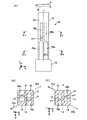
図1(A)は、本発明による屈曲振動片の第1実施例を概略的に示している。本実施例の屈曲振動片11は、基部12から平行に延長する1本の振動腕13を有する。振動腕13の表裏主面14,15には、前記基部との結合部から長手方向に延長する第1溝部及び第2溝部が形成されている。圧電振動片11は水晶で一体に形成され、水晶結晶軸の電気軸X軸を前記振動腕の幅方向に、機械軸Y軸を前記振動腕の長手方向に、光学軸Z軸を前記振動片の厚さ方向に配向している。別の実施例では、水晶以外の圧電材料やシリコン等の半導体材料で形成することもできる。
FIG. 1A schematically shows a first embodiment of a bending vibration piece according to the present invention. The
表側主面14の前記第1溝部は、振動腕13の長手方向に沿って同じ幅、長さ及び深さを有する2つの第1溝部分16a,16bに分割されている。前記第1溝部分は、振動腕13の長手方向の中心線iに関してその幅方向の両側に交互にずらして配置される。具体的には、基端側即ち前記基部に近い側の第1溝部分16aが、前記中心線iに関して幅方向の片側即ち図中右側に配置され、先端側即ち前記基部から遠い側の第1溝部分16bが、前記中心線iに関して幅方向の反対側即ち図中左側に配置されている。
The first groove portion of the front
裏側主面15の前記第2溝部は、同様に振動腕13の長手方向に沿って同じ幅、長さ及び深さを有する2つの第2溝部分17a,17bに分割されている。前記第2溝部分は、振動腕13の長手方向の中心線iに関してその幅方向の両側に交互にずらして配置される。具体的には、基端側の第2溝部分17aが、前記中心線iに関して幅方向の片側即ち図中左側に配置され、先端側の第2溝部分17bが、前記中心線iに関して幅方向の反対側即ち図中右側に配置されている。
Similarly, the second groove portion of the back-side
第1溝部分16a,16b及び第2溝部分17a,17bは、図1(B)(C)に示すように、深さが振動腕13の厚さの1/2より大きく、前記振動腕の側面から見て互いに重複している。前記振動腕の長手方向に互いに対応する位置にある第1溝部分16a,16bと第2溝部分17a,17bとは、前記振動腕の表裏主面から見て互いに重複しないように、その中心線iに関して互いに幅方向の反対側に配置されている。従って、振動腕13の第1及び第2溝部分16a,17aが設けられた基端側部分と、第1及び第2溝部分16b,17bが設けられた先端側部分とは、互いに鏡面対称をなすS字形の断面形状を有する。
As shown in FIGS. 1B and 1C, the
振動腕13の断面を幅方向及び厚さ方向の中心線で分割すると、前記基端側部分は、図1(B)に示すように、第1及び第2溝部分16a,17aの占有面積が少ない−X・+Z領域及び+X・−Z領域の質量が、−X・−Z領域及び+X・+Z領域よりも大きい。振動腕13の前記先端側部分は、図1(C)に示すように、第1及び第2溝部分16b,17bの占有面積が少ない−X・−Z領域及び+X・+Z領域の質量が、−X・+Z領域及び+X・−Z領域よりも大きい。
When the cross section of the vibrating
第1溝部分16a,16b及び第2溝部分17a,17bには、それぞれ振動腕13の側面に隣接する側面に第1励振電極(図示せず)が形成され、かつ前記振動腕の両側面には、それぞれ第2励振電極(図示せず)が形成されている。前記第1励振電極と前記第2励振電極とに所定の交流電圧を印加すると、振動腕13は図1(A)の矢印A,Bの向きに屈曲振動する。
The
このとき、振動腕13の前記基端側部分は、図1(B)の矢印Aa,Baで示すように、断面中心から質量の大きい−X・+Z方向及び+X・−Z方向に屈曲しようとする。これに対し、振動腕13の前記先端側部分は、図1(C)の矢印Ab,Bbで示すように、断面中心から同じく質量の大きい−X・−Z方向及び+X・+Z方向に屈曲しようとする。この結果、振動腕13全体として、±Z方向の振動成分が打ち消し合うことになる。
At this time, as shown by arrows Aa and Ba in FIG. 1B, the base end side portion of the vibrating
これにより、振動腕13は、±Z方向の変位が解消又は十分に抑制され、振動エネルギーを表裏主面14,15の面内方向に閉じ込めることができる。従って、屈曲振動片11のQ値を向上させ、CI値を抑制することができ、その結果小型化、薄型化を促進することができる。
Thereby, the
図2(A)は、本発明による圧電振動片の第2実施例を概略的に示している。本実施例の屈曲振動片18は、基端側の第1溝部分19a及び第2溝部分20aの幅w1が、先端側の第1溝部分19b及び第2溝部分20bの幅w2と異なり、かつw1>w2である点において、図1の第1実施例と異なる。
FIG. 2A schematically shows a second embodiment of the piezoelectric vibrating piece according to the present invention. In the
振動腕13を図2(A)の矢印A,Bの向きに屈曲振動させると、振動腕13の基端側部分は、図2(B)の矢印Aa,Baで示すように、断面中心から質量の大きい−X・+Z方向及び+X・−Z方向に屈曲しようとする。これに対し、振動腕13の先端側部分は、図2(C)の矢印Ab,Bbで示すように、断面中心から同じく質量の大きい−X・−Z方向及び+X・+Z方向に屈曲しようとする。
When the vibrating
振動腕13の面外方向の変位には、前記振動腕の基端側に発生する応力が先端側に発生する応力よりも大きく寄与することが確認されている。従って、上述したように第1及び第2溝部分19a,19b,20a,20bの幅を基端側と先端側とで異なる大きさに設定することによって、振動腕13全体として面外方向の振動成分をより良好に打ち消し合わせ、面外方向の変位を解消又は抑制することができる。従って、屈曲振動片18のQ値をより向上させ、CI値をより効果的に抑制することができる。
It has been confirmed that the stress generated on the base end side of the vibrating arm contributes more to the displacement in the out-of-plane direction of the vibrating
図3(A)は、本発明による圧電振動片の第3実施例を概略的に示している。本実施例の屈曲振動片21は、基端側の第1溝部分22a及び第2溝部分23aの長さL1が、先端側の第1溝部分22b及び第2溝部分23bの長さL2と異なり、かつL1<L2である点において、図1の第1実施例と異なる。
FIG. 3A schematically shows a third embodiment of the piezoelectric vibrating piece according to the present invention. In the bending
振動腕13を図3(A)の矢印A,Bの向きに屈曲振動させると、振動腕13の基端側部分は、図3(B)の矢印Aa,Baで示すように、断面中心から質量の大きい−X・+Z方向及び+X・−Z方向に屈曲しようとする。これに対し、振動腕13の先端側部分は、図3(C)の矢印Ab,Bbで示すように、断面中心から同じく質量の大きい−X・−Z方向及び+X・+Z方向に屈曲しようとする。
When the vibrating
振動腕13の面外方向の変位には、前記振動腕の基端側に発生する応力が先端側に発生する応力よりも大きく寄与することが確認されている。従って、上述したように第1及び第2溝部分22a,22b,23a,23bの長さを基端側と先端側とで異なる大きさに設定することによって、振動腕13全体として面外方向の振動成分をより良好に打ち消し合わせ、面外方向の変位を解消又は抑制することができる。従って、屈曲振動片18のQ値をより向上させ、CI値をより効果的に抑制することができる。
It has been confirmed that the stress generated on the base end side of the vibrating arm contributes more to the displacement in the out-of-plane direction of the vibrating
別の実施例では、第3実施例に第2実施例を組み合わせることができる。例えば、基端側の第1溝部分22a及び第2溝部分23aの幅を、先端側の第1溝部分22b及び第2溝部分23bの幅よりも大きくし、又は小さくすることができる。
In another embodiment, the second embodiment can be combined with the third embodiment. For example, the width of the
図4(A)は、本発明による圧電振動片の第4実施例を概略的に示している。本実施例の屈曲振動片24は、表側主面14の第1溝部が振動腕13の長手方向に沿って同じ幅、長さ及び深さを有する3つの第1溝部分25a〜25cに分割され、かつ裏側主面15の第2溝部が同じく振動腕13の長手方向に沿って同じ幅、長さ及び深さを有する3つの第2溝部分26a〜26cに分割されている点において、図1の第1実施例と異なる。第1溝部分25a〜25cは、振動腕13の長手方向の中心線iに関してその幅方向の両側に交互にずらして配置されている。第2溝部分26a〜26cは、前記中心線iに関してその幅方向の両側に交互にずらして、かつ第1溝部分25a〜25cに対して前記振動腕の表裏主面から見て互いに重複しないように、前記中心線iに関して互いに幅方向の反対側に配置されている。
FIG. 4A schematically shows a fourth embodiment of the piezoelectric vibrating piece according to the present invention. The bending vibration piece 24 of the present embodiment is divided into three
振動腕13を図4(A)の矢印A,Bの向きに屈曲振動させると、振動腕13の基端側部分は、図4(B)の矢印Aa,Baで示すように、断面中心から質量の大きい−X・+Z方向及び+X・−Z方向に屈曲しようとする。振動腕13の中央部分は、図4(C)の矢印Ab,Bbで示すように、断面中心から質量の大きい−X・−Z方向及び+X・+Z方向に屈曲しようとする。振動腕13の先端側部分は、前記基端側部分と同様に、図4(C)の矢印Ab,Bbで示すように、断面中心から質量の大きい−X・+Z方向及び+X・−Z方向に屈曲しようとする。
When the vibrating
このように分割した第1及び第2溝部分の数を増やすことによって、振動腕の幅方向に各第1及び第2溝部分の配置が変わる毎に、振動腕13の基端側から先端側に長さ方向に沿って面外振動成分の向きがより頻繁に繰り返して逆方向に変化する。その結果、振動腕全体として面内方向によりスムーズに屈曲振動させることができる。別の実施例では、前記第1及び第2溝部を4つ以上の第1及び第2溝部分に分割することができる。
By increasing the number of the first and second groove portions divided in this way, each time the arrangement of the first and second groove portions is changed in the width direction of the vibrating arm, the proximal end side to the distal end side of the vibrating
また、別の実施例では、第4実施例に第2、第3実施例を別々に又は両方共組み合わせて実施することができる。例えば、振動腕13の長手方向に沿って第1溝部分25a〜25c及び第2溝部分26a〜26cを互いに異なる長さに設定し、又は互いに異なる幅に設定し、又は互いに異なる長さ及び幅に設定することができる。
In another embodiment, the second and third embodiments can be implemented separately or in combination with the fourth embodiment. For example, the
図5(A)は、本発明による圧電振動片の第5実施例を概略的に示している。本実施例の屈曲振動片31は、基部32から平行に延長する1対の振動腕33,34を有する音叉型の屈曲振動片である。
FIG. 5A schematically shows a fifth embodiment of the piezoelectric vibrating piece according to the present invention. The flexural vibration piece 31 of the present embodiment is a tuning fork type flexural vibration piece having a pair of
振動腕33の表裏主面35,36には、それぞれ前記基部との結合部から長手方向に延長する第1溝部及び第2溝部が形成されている。表側主面35の前記第1溝部は、振動腕13の長手方向に沿って同じ幅、長さ及び深さを有する2つの第1溝部分37a,37bに分割され、前記各第1溝部分は、振動腕33の長手方向の中心線iに関してその幅方向の両側に交互にずらして配置されている。裏側主面36の前記第2溝部は、同じく振動腕33の長手方向に沿って同じ幅、長さ及び深さを有する2つの第2溝部分38a,38bに分割され、前記各第2溝部分は、前記中心線iに関してその幅方向の両側に交互にずらして配置されている。
The front and back
同様に振動腕34の表裏主面39,40には、それぞれ前記基部との結合部から長手方向に延長する第1溝部及び第2溝部が形成されている。表側主面39の前記第1溝部は、振動腕34の長手方向に沿って同じ幅、長さ及び深さを有する2つの第1溝部分41a,41bに分割され、前記各第1溝部分は、振動腕33の長手方向の中心線iに関してその幅方向の両側に交互にずらして配置されている。裏側主面40の前記第2溝部は、同じく振動腕34の長手方向に沿って同じ幅、長さ及び深さを有する2つの第2溝部分42a,42bに分割され、前記各第2溝部分は、前記中心線iに関してその幅方向の両側に交互にずらして配置されている。
Similarly, the front and back
両振動腕33,34の表側主面35,39の前記第1溝部は、図5(B)(C)に示すように、前記両振動腕間の中心線i’に関して対称に設けられ、基端側の第1溝部分37a,41aが互いに隣接する側に配置され、かつ先端側の第1溝部分37b,41bが互いに反対側に配置されている。両振動腕33,34の裏側主面36,40の前記第2溝部は、同様に前記両振動腕間の中心線i’に関して対称に設けられているが、逆に先端側の第1溝部分38b,42bが互いに隣接する側に配置され、かつ基端側の第1溝部分38a,42aが互いに反対側に配置されている。これにより、両振動腕33,34の基端側部分及び先端側部分は、それぞれが互いに前記中心線i’に関して線対称のS字形の断面形状を有する。
As shown in FIGS. 5B and 5C, the first groove portions of the front
図5(B)に示すように、振動腕33の断面を幅方向及び厚さ方向の中心線で分割すると、その基端側部分は、第1及び第2溝部分36a,38aの占有面積が少ない−X・+Z領域及び+X・−Z領域の質量が、−X・−Z領域及び+X・+Z領域よりも大きい。振動腕33と線対称の断面形状を有する振動腕33の基端側部分は、第1及び第2溝部分41a,42aの占有面積が少ない+X・+Z領域及び−X・−Z領域の質量が、−X・+Z領域及び+X・−Z領域よりも大きい。
As shown in FIG. 5B, when the cross section of the vibrating
図5(C)に示すように、振動腕33の先端側部分は、第1及び第2溝部分37b,38bの占有面積が少ない−X・−Z領域及び+X・+Z領域の質量が、−X・+Z領域及び+X・−Z領域よりも大きい。これと対称的に、振動腕34の先端側部分は、第1及び第2溝部分41b,42bの占有面積が少ない+X・−Z領域及び−X・+Z領域の質量が、−X・−Z領域及び+X・+Z領域よりも大きい。
As shown in FIG. 5C, the tip side portion of the vibrating
振動腕33,34の前記第1溝部及び第2溝部には、それぞれ内面に第1励振電極(図示せず)が形成され、かつ前記各振動腕の両側面には、それぞれ第2励振電極(図示せず)が形成されている。一方の前記振動腕の第1励振電極と他方の前記振動腕の第2励振電極とが互いに接続され、それらに交流電圧を印加することによって、前記両振動腕が、図5(A)の矢印A,Bで示すように、互いに接近又は離反する向きに振動する。
A first excitation electrode (not shown) is formed on the inner surface of each of the first groove portion and the second groove portion of the vibrating
このとき、振動腕33の基端側部分は、図5(B)の矢印Aa1,Ba1で示すように、断面中心から質量の大きい−X・+Z方向及び+X・−Z方向に屈曲しようとする。振動腕34の基端側部分は、図5(B)の矢印Aa2,Ba2で示すように、断面中心から質量の大きい+X・+Z方向及び−X・−Z方向に屈曲しようとする。これに対し、振動腕33の先端側部分は、図5(C)の矢印Ab1,Bb1で示すように、断面中心から質量の大きい−X・−Z方向及び+X・+Z方向に屈曲しようとする。振動腕34の先端側部分は、図5(C)の矢印Ab2,Bb2で示すように、断面中心から質量の大きい+X・−Z方向及び−X・+Z方向に屈曲しようとする。
At this time, as shown by arrows Aa1 and Ba1 in FIG. 5B, the base end side portion of the vibrating
このように、両振動腕33,34の基端側部分は、互いにZ方向の同じ向きに面外振動成分を有し、かつそれらの先端側部分は、互いにZ方向の同じ向きであって前記基端側部分とは逆向きに面外振動成分を有する。この結果、各振動腕33,34は、それぞれ全体として±Z方向の振動成分が打ち消し合い、±Z方向の変位が解消又は抑制される。従って、屈曲振動片31は、Q値を向上させかつCI値を抑制することができ、その結果小型化、薄型化を促進することができる。
In this way, the proximal end portions of the vibrating
図6(A)は、本発明による圧電振動片の第6実施例を概略的に示している。本実施例の屈曲振動片43は、第5実施例の変形であって、基部32から平行に延長する1対の振動腕33,34を有する音叉型の屈曲振動片である。一方の振動腕33は、第5実施例と同一の構成を有し、表側主面35の基端側の第1溝部分44aが他方の振動腕34に隣接する側にかつ先端側の第1溝部分44bがそれとは反対側に配置され、裏側主面36の先端側の第2溝部分45bが他方の振動腕34に隣接する側にかつ基端側の第2溝部分45aがそれとは反対側に配置されている。
FIG. 6A schematically shows a sixth embodiment of the piezoelectric vibrating piece according to the present invention. The bending
これに対し、他方の振動腕34は、表側主面35の先端側の第1溝部分46bが他方の振動腕34に隣接する側にかつ基端側の第1溝部分46aがそれとは反対側に配置され、裏側主面36の基端側の第2溝部分47aが他方の振動腕34に隣接する側にかつ先端側の第2溝部分47bがそれとは反対側に配置されている点において、第5実施例の屈曲振動片31と異なる。これにより、両振動腕33,34の基端側部分及び先端側部分は、図6(B)(C)に示すように、それぞれが互いに前記両振動腕間の中心Oに関して点対称のS字形の断面形状を有する。
On the other hand, in the other vibrating
従って、屈曲振動片43を図6(A)の矢印A,Bで示すように、互いに接近又は離反する向きに振動させると、振動腕33の基端側部分は、図6(B)の矢印Aa1,Ba1で示すように、断面中心から質量の大きい−X・+Z方向及び+X・−Z方向に屈曲しようとする。振動腕34の基端側部分は、図6(B)の矢印Aa2,Ba2で示すように、断面中心から質量の大きい+X・−Z方向及び−X・+Z方向に屈曲しようとする。これに対し、振動腕33の先端側部分は、図6(C)の矢印Ab1,Bb1で示すように、断面中心から質量の大きい−X・−Z方向及び+X・+Z方向に屈曲しようとする。振動腕34の先端側部分は、図6(C)の矢印Ab2,Bb2で示すように、断面中心から質量の大きい+X・+Z方向及び−X・−Z方向に屈曲しようとする。
Accordingly, when the
このように、両振動腕33,34の基端側部分は、互いにZ方向の逆向きに面外振動成分を有し、かつそれらの先端側部分は、互いにZ方向の逆向きであって前記基端側部分とも逆向きに面外振動成分を有する。この結果、各振動腕33,34は、同様にそれぞれ全体として±Z方向の振動成分が打ち消し合い、±Z方向の変位が解消又は抑制される。従って、屈曲振動片43は、Q値を向上させかつCI値を抑制することができ、その結果小型化、薄型化を促進することができる。
As described above, the base end portions of the vibrating
別の実施例では、図5及び図6の屈曲振動片31,43において、各振動腕33,34を上記第2乃至第4実施例と同様に構成し、又はそれらを組み合わせて適用することができる。また別の実施例では、3本以上の振動腕を有する音叉型の屈曲振動片についても、本発明を同様に適用することができる。
In another embodiment, in the bending
図7(A)は、本発明による圧電振動片の第7実施例を概略的に示している。本実施例の屈曲振動片51は、第5及び第6実施例と同様に、基部52から平行に延長する1対の振動腕53,54を有する音叉型の屈曲振動片である。しかしながら、振動腕53,54が、図7(A)に矢印A〜Dで示すように、ウォーク振動とも呼ばれる逆相の屈曲振動モードで該振動腕の表裏面に対して垂直方向に振動する点において、第5及び第6実施例の音叉型屈曲振動片と異なる。圧電振動片51も水晶で一体に形成されるが、上記各実施例と異なり、水晶結晶軸の電気軸X軸を前記振動片の厚さ方向に、機械軸Y軸を前記振動腕の長手方向に、光学軸Z軸を前記振動片の幅方向に配向している。別の実施例では、水晶以外の圧電材料やシリコン等の半導体材料で形成することもできる。
FIG. 7A schematically shows a seventh embodiment of the piezoelectric vibrating piece according to the present invention. The
屈曲振動片51は、振動腕53,54の幅方向に互いに対向する第1及び第2の主面を有する。一方の振動腕53は、他方の振動腕54と対向する側に第1の主面55を、それとは反対側に第2の主面56を有し、それぞれ前記基部との結合部から長手方向に延長する第1溝部及び第2溝部が形成されている。第1の主面55の前記第1溝部は、振動腕53の長手方向に沿って同じ幅、長さ及び深さを有する2つの第1溝部分57a,57bに分割され、これら第1溝部分は、振動腕53の長手方向の中心線i1に関してその両側に交互にずらして配置されている。第2の主面56の前記第2溝部は、同じく振動腕53の長手方向に沿って同じ幅、長さ及び深さを有する2つの第2溝部分58a,58bに分割され、これら第2溝部分は、振動腕53の長手方向の中心線i2に関してその両側に交互にずらして配置されている。
The bending
同様に他方の振動腕54は、前記一方の振動腕とは反対側に第1の主面59を、それと対向する側に第2の主面60を有し、それぞれ前記基部との結合部から長手方向に延長する第1溝部及び第2溝部が形成されている。第1の主面59の前記第1溝部は、振動腕54の長手方向に沿って同じ幅、長さ及び深さを有する2つの第1溝部分61a,61bに分割され、これら第1溝部分は、振動腕54の長手方向の中心線i1に関してその両側に交互にずらして配置されている。第2の主面60の前記第2溝部は、同じく振動腕54の長手方向に沿って同じ幅、長さ及び深さを有する2つの第2溝部分62a,62bに分割され、これら第2溝部分は、振動腕54の長手方向の中心線i2に関してその両側に交互にずらして配置されている。
Similarly, the other vibrating
これにより、両振動腕53,54の基端側部分及び先端側部分は、図7(B)(C)に示すように、それぞれが互いに前記両振動腕間の中心Oに関して点対称のS字形の断面形状を有する。従って、屈曲振動片51を上述したように逆相で屈曲振動させると、振動腕53の基端側部分は、図7(B)の矢印Aa,Caで示すように、断面中心から質量の大きい−X・−Z方向及び+X・+Z方向に屈曲しようとする。振動腕54の基端側部分は、図7(B)の矢印Ba,Daで示すように、断面中心から質量の大きい+X・+Z方向及び−X・−Z方向に屈曲しようとする。これに対し、振動腕53の先端側部分は、図7(C)の矢印Ab,Cbで示すように、断面中心から質量の大きい−X・+Z方向及び+X・−Z方向に屈曲しようとする。振動腕54の先端側部分は、図7(C)の矢印Bb,Dbで示すように、断面中心から質量の大きい+X・−Z方向及び−X・+Z方向に屈曲しようとする。
As a result, as shown in FIGS. 7B and 7C, the proximal end portion and the distal end portion of both the vibrating
このように、両振動腕53,54の基端側部分と先端側部分とは、互いにZ方向に逆向きの面外振動成分を有する。この結果、各振動腕53,54は、それぞれ全体として±Z方向の振動成分が打ち消し合い、±Z方向の変位が解消又は抑制される。従って、屈曲振動片51は、Q値を向上させかつCI値を抑制することができ、その結果小型化、薄型化を促進することができる。
As described above, the proximal end portion and the distal end portion of the vibrating
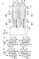
図8(A)は、本発明による圧電振動片の第8実施例を概略的に示している。本実施例の屈曲振動片71は、第7実施例の変形例であり、基部72から平行に延長する3本の振動腕73〜75を有する。振動腕73〜75は、同図に矢印A〜Fで示すように、交互に逆相の振動屈曲モードで振動片表面に対して垂直方向に振動し、各振動腕の幅方向に互いに対向する第1の主面76,78,80と第2の主面77,79,81とを有する。
FIG. 8A schematically shows an eighth embodiment of the piezoelectric vibrating piece according to the present invention. The bending vibration piece 71 of the present embodiment is a modification of the seventh embodiment, and includes three vibrating
第7実施例と同様に、各振動腕73〜75の前記第1及び第2の主面には、それぞれ前記基部との結合部から長手方向に延長する第1溝部及び第2溝部が形成されている。図中左端の振動腕73の前記第1溝部及び第2溝部は、それぞれ長手方向に沿って同じ幅、長さ及び深さを有する2つの第1溝部分82a,82b及び第2溝部分83a,83bに分割されている。第1溝部分82a,82bと第2溝部分83a,83bとは、それぞれが振動腕73の長手方向の中心線i1,i2に関してその両側に交互にずらして配置され、かつ前記中心線線i1,i2に関して互いに反対側に配置されている。
Similar to the seventh embodiment, the first and second main surfaces of the vibrating
同様に図中中央の振動腕74の前記第1溝部及び第2溝部は、それぞれ長手方向に沿って同じ幅、長さ及び深さを有する2つの第1溝部分84a,84b及び第2溝部分85a,85bに分割されている。第1溝部分84a,84bと第2溝部分85a,85bとは、それぞれが振動腕74の長手方向の中心線i1,i2に関してその両側に交互にずらして配置され、かつ前記中心線に関して互いに反対側に配置されている。
Similarly, the first groove portion and the second groove portion of the vibrating
更に図中右端の振動腕75の前記第1溝部及び第2溝部は、それぞれ長手方向に沿って同じ幅、長さ及び深さを有する2つの第1溝部分86a,86b及び第2溝部分87a,87bに分割されている。第1溝部分86a,86bと第2溝部分87a,87bとは、それぞれが振動腕75の中心線i1,i2に関してその両側に交互にずらして配置され、かつ前記中心線に関して互いに反対側に配置されている。
Further, the first groove portion and the second groove portion of the vibrating
これにより、各振動腕73〜75の基端側部分及び先端側部分は、図8(B)(C)に示すように、それぞれが互いに隣接する前記振動腕間の中心O1、O2に関して点対称のS字形の断面形状を有する。従って、屈曲振動片71を上述したように逆相で屈曲振動させると、各振動腕73〜75の基端側部分は、断面中心から質量の大きい−X・−Z方向及び+X・+Z方向に屈曲しようとする。前記各振動腕の先端側部分は、断面中心から質量の大きい−X・+Z方向及び+X・−Z方向に屈曲しようとする。
As a result, the base end portion and the tip end portion of each of the vibrating
このように、各振動腕73〜75の基端側部分と先端側部分とは、互いにZ方向に逆向きの面外振動成分を有する。この結果、各振動腕73〜75は、それぞれ全体として±Z方向の振動成分が打ち消し合い、±Z方向の変位が解消又は抑制される。従って、屈曲振動片71は、Q値を向上させかつCI値を抑制することができ、その結果小型化、薄型化を促進することができる。
As described above, the proximal end portion and the distal end portion of each of the vibrating
別の実施例では、図7及び図8の屈曲振動片51,71において、各振動腕を上記第2乃至第4実施例と同様に構成することができる。また、別の実施例では、各振動腕間において、図5の音叉型屈曲振動片のように、基端側の第1及び第2溝部分と先端側の第1及び第2溝部分とを振動腕の中心線に関して逆の位置に配置することができる。
In another embodiment, in each of the bending
本発明は、上記実施例に限定されるものでなく、その技術的範囲内で様々な変形又は変更を加えて実施することができる。例えば、第1及び第2溝部分の深さは、振動腕全体として±Z方向の変位を解消又は抑制できる限り、振動腕の長手方向に沿って各溝部分毎に変更することができる。 The present invention is not limited to the above embodiments, and can be implemented with various modifications or changes within the technical scope thereof. For example, the depths of the first and second groove portions can be changed for each groove portion along the longitudinal direction of the vibrating arm as long as the displacement in the ± Z direction can be eliminated or suppressed as the entire vibrating arm.
1,7…音叉型圧電振動片、2,12,32,52,72…基部、3,4,13,33,34,53,54,73〜75…振動腕、5a,6a,8a,9a…第1溝部、5b,6b,8b,9b…第2溝部、11,18,21,24,31,43,51,71…屈曲振動片、14,15,35,36,39,40,55,56,59,60,76〜81…主面、16a,16b,19a,19b,22a,22b,25a〜25c,37a,37b,41a,41b,44a,44b,46a,46b,57a,57b,61a,61b,82a,82b,84a,84b,86a,86b…第1溝部分、17a,17b,20a,20b,23a,23b,26a〜26c,38a,38b,42a,42b,45a,45b,47a,47b,58a,58b,62a,62b,83a,83b,85a,85b,87a,87b…第2溝部分。
DESCRIPTION OF
Claims (6)
表裏の関係にある第1及び第2の主面を有しており、かつ前記基部から延在している振動腕と、を備え、
前記第1の主面が、前記振動腕の長手方向の中心線を境にして両側に前記長手方向に沿って交互にずらして配置されている複数の第1溝部分を有し、
前記第2の主面が、前記振動腕の長手方向の中心線を境にして両側に前記長手方向に沿って交互にずらして配置されている複数の第2溝部分を有し、
前記第1溝部分、前記第2溝部分、及び前記振動腕の両側面に励振電極を備えていることを特徴とする屈曲振動片。 The base,
It has first and second main surfaces in the front and back relationship, and provided with a vibrating arm extending from the base,
It said first major surface has a longitudinal direction a plurality of first groove portions along the longitudinal direction on both sides of the center line as a boundary are arranged offset alternately in the vibrating arm,
The second main surface has a longitudinal plurality of second groove portions along the longitudinal direction on both sides of the center line as a boundary are arranged offset alternately in the vibrating arm,
A flexural vibration piece comprising excitation electrodes on both side surfaces of the first groove portion, the second groove portion, and the vibrating arm.
Priority Applications (3)
| Application Number | Priority Date | Filing Date | Title |
|---|---|---|---|
| JP2009111256A JP5272880B2 (en) | 2009-04-30 | 2009-04-30 | Bending vibration piece |
| US12/767,851 US7932664B2 (en) | 2009-04-30 | 2010-04-27 | Flexural vibration piece |
| CN201010170631XA CN101877575B (en) | 2009-04-30 | 2010-04-30 | Flexural vibration piece |
Applications Claiming Priority (1)
| Application Number | Priority Date | Filing Date | Title |
|---|---|---|---|
| JP2009111256A JP5272880B2 (en) | 2009-04-30 | 2009-04-30 | Bending vibration piece |
Publications (3)
| Publication Number | Publication Date |
|---|---|
| JP2010263317A JP2010263317A (en) | 2010-11-18 |
| JP2010263317A5 JP2010263317A5 (en) | 2012-06-28 |
| JP5272880B2 true JP5272880B2 (en) | 2013-08-28 |
Family
ID=43020052
Family Applications (1)
| Application Number | Title | Priority Date | Filing Date |
|---|---|---|---|
| JP2009111256A Expired - Fee Related JP5272880B2 (en) | 2009-04-30 | 2009-04-30 | Bending vibration piece |
Country Status (3)
| Country | Link |
|---|---|
| US (1) | US7932664B2 (en) |
| JP (1) | JP5272880B2 (en) |
| CN (1) | CN101877575B (en) |
Families Citing this family (20)
| Publication number | Priority date | Publication date | Assignee | Title |
|---|---|---|---|---|
| TW201032470A (en) * | 2008-10-24 | 2010-09-01 | Seiko Epson Corp | Bending vibration piece, bending vibrator, and piezoelectric device |
| JP5272880B2 (en) * | 2009-04-30 | 2013-08-28 | セイコーエプソン株式会社 | Bending vibration piece |
| JP5482541B2 (en) | 2009-10-01 | 2014-05-07 | セイコーエプソン株式会社 | Vibrating piece, vibrator, oscillator, and electronic device |
| US20110215680A1 (en) * | 2010-03-05 | 2011-09-08 | Seiko Epson Corporation | Resonator element, resonator, oscillator, and electronic device |
| JP2012249246A (en) * | 2011-05-31 | 2012-12-13 | Kyocera Crystal Device Corp | Tuning-fork type flexural crystal vibration element |
| JP2012249244A (en) * | 2011-05-31 | 2012-12-13 | Kyocera Crystal Device Corp | Tuning-fork type flexural crystal vibration element |
| JP5724672B2 (en) * | 2011-06-24 | 2015-05-27 | セイコーエプソン株式会社 | Bending vibration piece, manufacturing method thereof, and electronic device |
| JP5839919B2 (en) * | 2011-09-28 | 2016-01-06 | エスアイアイ・クリスタルテクノロジー株式会社 | Piezoelectric vibrating piece, piezoelectric vibrator, oscillator, electronic device, and radio clock |
| KR101532115B1 (en) * | 2011-12-01 | 2015-06-29 | 삼성전기주식회사 | Piezo vibrator and method for manufacturing the same |
| JP2013192013A (en) * | 2012-03-13 | 2013-09-26 | Seiko Epson Corp | Vibration element, vibration device and electronic apparatus |
| JP2013251672A (en) * | 2012-05-31 | 2013-12-12 | Seiko Epson Corp | Vibration piece, electronic device, electronic apparatus and manufacturing method for vibration piece |
| JP6080449B2 (en) | 2012-09-18 | 2017-02-15 | エスアイアイ・クリスタルテクノロジー株式会社 | Piezoelectric vibrating piece, piezoelectric vibrator, oscillator, electronic device and radio clock |
| JP6155897B2 (en) * | 2013-06-24 | 2017-07-05 | セイコーエプソン株式会社 | Vibrating piece, vibrator, electronic device, electronic device, and moving object |
| JP6435596B2 (en) * | 2013-08-09 | 2018-12-12 | セイコーエプソン株式会社 | Vibration element, vibration device, electronic device, and moving object |
| JP6582501B2 (en) * | 2015-04-02 | 2019-10-02 | セイコーエプソン株式会社 | Vibration element, vibrator, electronic device and moving body |
| EP3468036A1 (en) | 2017-10-03 | 2019-04-10 | Micro Crystal AG | Small piezoelectric resonator |
| US10665368B2 (en) * | 2018-04-17 | 2020-05-26 | 3M Innovative Properties Company | Cable support |
| WO2019211926A1 (en) * | 2018-05-02 | 2019-11-07 | 株式会社村田製作所 | Resonator and resonation device |
| CN114189228B (en) * | 2021-11-16 | 2022-09-02 | 苏州亿波达光电子科技有限公司 | Quartz tuning fork resonator and preparation method thereof |
| CN114157268B (en) * | 2021-12-06 | 2022-12-20 | 苏州亿波达光电子科技有限公司 | Quartz crystal resonator and manufacturing method thereof |
Family Cites Families (22)
| Publication number | Priority date | Publication date | Assignee | Title |
|---|---|---|---|---|
| JPS5393792A (en) * | 1977-01-26 | 1978-08-17 | Seiko Instr & Electronics Ltd | Crystal vibrator |
| FR2467487A1 (en) * | 1979-10-15 | 1981-04-17 | Ebauches Sa | PIEZOELECTRIC RESONATOR |
| JP2625511B2 (en) | 1988-07-21 | 1997-07-02 | 株式会社クボタ | Grain distribution detector for grain sorter |
| JPH06112760A (en) * | 1992-09-25 | 1994-04-22 | Seiko Electronic Components Ltd | Tortion crystal vibrator |
| WO2000044092A1 (en) | 1999-01-20 | 2000-07-27 | Seiko Epson Corporation | Vibrator and electronic device with vibrator |
| JP2002261575A (en) | 2000-12-25 | 2002-09-13 | Seiko Epson Corp | Vibrating piece, vibrator, oscillator and electronic equipment |
| JP3900846B2 (en) * | 2001-03-02 | 2007-04-04 | セイコーエプソン株式会社 | Tuning fork type crystal vibrating piece, vibrator, oscillator and portable telephone device |
| JP2004135052A (en) * | 2002-10-10 | 2004-04-30 | Nippon Dempa Kogyo Co Ltd | Tuning fork type vibrator |
| JP4281348B2 (en) * | 2002-12-17 | 2009-06-17 | セイコーエプソン株式会社 | Piezoelectric vibrating piece, piezoelectric device using the piezoelectric vibrating piece, mobile phone device using the piezoelectric device, and electronic equipment using the piezoelectric device |
| JP4257138B2 (en) * | 2003-02-12 | 2009-04-22 | 京セラキンセキヘルツ株式会社 | Tuning fork crystal unit |
| JP2004260718A (en) | 2003-02-27 | 2004-09-16 | Seiko Epson Corp | Tuning fork type vibration pieces, manufacturing method of tuning fork type vibration pieces, and piezoelectric device |
| JP4316903B2 (en) * | 2003-03-11 | 2009-08-19 | リバーエレテック株式会社 | Flexural vibrator |
| JP4593203B2 (en) * | 2004-08-24 | 2010-12-08 | リバーエレテック株式会社 | Tuning fork crystal unit and method for manufacturing the same |
| EP1672315B1 (en) * | 2004-12-20 | 2007-09-26 | ETA SA Manufacture Horlogère Suisse | Transducer for measuring angular velocity |
| JP4638263B2 (en) * | 2005-03-23 | 2011-02-23 | リバーエレテック株式会社 | Tuning fork type bending vibrator |
| JP4404218B2 (en) * | 2006-03-29 | 2010-01-27 | セイコーエプソン株式会社 | Tuning fork vibrator and manufacturing method thereof |
| JP2007285879A (en) * | 2006-04-17 | 2007-11-01 | Seiko Epson Corp | Angular velocity sensor and manufacturing method therefor |
| JP4687790B2 (en) * | 2006-07-21 | 2011-05-25 | 株式会社村田製作所 | Sound piece type vibrator and vibration gyro using the same |
| JP4578499B2 (en) * | 2007-03-30 | 2010-11-10 | 京セラキンセキ株式会社 | Tuning fork-type bending crystal resonator, crystal resonator and crystal oscillator having the same |
| US8234774B2 (en) * | 2007-12-21 | 2012-08-07 | Sitime Corporation | Method for fabricating a microelectromechanical system (MEMS) resonator |
| JP2010193133A (en) * | 2009-02-18 | 2010-09-02 | Epson Toyocom Corp | Bending vibrator piece and bending vibrator |
| JP5272880B2 (en) * | 2009-04-30 | 2013-08-28 | セイコーエプソン株式会社 | Bending vibration piece |
-
2009
- 2009-04-30 JP JP2009111256A patent/JP5272880B2/en not_active Expired - Fee Related
-
2010
- 2010-04-27 US US12/767,851 patent/US7932664B2/en not_active Expired - Fee Related
- 2010-04-30 CN CN201010170631XA patent/CN101877575B/en not_active Expired - Fee Related
Also Published As
| Publication number | Publication date |
|---|---|
| CN101877575A (en) | 2010-11-03 |
| US7932664B2 (en) | 2011-04-26 |
| JP2010263317A (en) | 2010-11-18 |
| US20100277041A1 (en) | 2010-11-04 |
| CN101877575B (en) | 2013-05-08 |
Similar Documents
| Publication | Publication Date | Title |
|---|---|---|
| JP5272880B2 (en) | Bending vibration piece | |
| KR101966126B1 (en) | A quartz vibration plate, and a quartz vibration device | |
| US7626318B2 (en) | Piezoelectric resonator with optimised motional capacitances | |
| JP5046012B2 (en) | Vibrating piece, vibrating device, oscillator and electronic device | |
| JP5071058B2 (en) | Piezoelectric vibrating piece | |
| JP4319657B2 (en) | Piezoelectric vibrator | |
| JP2011097183A5 (en) | Vibrating piece and vibrator | |
| JP2010252302A (en) | Bending vibrator piece and oscillator using the same | |
| JP2010263317A5 (en) | ||
| JP4879963B2 (en) | Piezoelectric vibrating piece, piezoelectric vibrator and piezoelectric oscillator | |
| US20170070206A1 (en) | Crystal unit | |
| JP2008236439A (en) | Quartz oscillating piece | |
| JP2010226608A (en) | Bent vibrating piece and oscillator employing the same | |
| JP2011082945A (en) | Flexural vibration piece, flexural vibrator, and electronic device | |
| JP5509647B2 (en) | Vibrating piece | |
| JP6719313B2 (en) | Piezoelectric resonator element and piezoelectric vibrator | |
| JP6424901B2 (en) | Resonator | |
| JP4993080B2 (en) | Tuning fork type piezoelectric vibrating piece | |
| JP2010232932A5 (en) | Vibrating piece | |
| JP5847540B2 (en) | Crystal wafer | |
| JP2004135052A (en) | Tuning fork type vibrator | |
| JP6400608B2 (en) | Planar structure of mechanical resonator separated by bending vibration and extension / compression vibration | |
| JP6525821B2 (en) | Tuning fork type crystal element | |
| JP5973212B2 (en) | Manufacturing method of tuning fork type piezoelectric vibrator | |
| WO2014119106A1 (en) | Tuning-fork-type quartz vibrator |
Legal Events
| Date | Code | Title | Description |
|---|---|---|---|
| A711 | Notification of change in applicant |
Free format text: JAPANESE INTERMEDIATE CODE: A711 Effective date: 20100924 |
|
| A521 | Request for written amendment filed |
Free format text: JAPANESE INTERMEDIATE CODE: A821 Effective date: 20100924 |
|
| A521 | Request for written amendment filed |
Free format text: JAPANESE INTERMEDIATE CODE: A523 Effective date: 20120420 |
|
| A621 | Written request for application examination |
Free format text: JAPANESE INTERMEDIATE CODE: A621 Effective date: 20120420 |
|
| RD04 | Notification of resignation of power of attorney |
Free format text: JAPANESE INTERMEDIATE CODE: A7424 Effective date: 20120726 |
|
| A977 | Report on retrieval |
Free format text: JAPANESE INTERMEDIATE CODE: A971007 Effective date: 20130404 |
|
| TRDD | Decision of grant or rejection written | ||
| A01 | Written decision to grant a patent or to grant a registration (utility model) |
Free format text: JAPANESE INTERMEDIATE CODE: A01 Effective date: 20130416 |
|
| A61 | First payment of annual fees (during grant procedure) |
Free format text: JAPANESE INTERMEDIATE CODE: A61 Effective date: 20130429 |
|
| R150 | Certificate of patent or registration of utility model |
Free format text: JAPANESE INTERMEDIATE CODE: R150 |
|
| LAPS | Cancellation because of no payment of annual fees |