JP2010252302A - Bending vibrator piece and oscillator using the same - Google Patents
Bending vibrator piece and oscillator using the same Download PDFInfo
- Publication number
- JP2010252302A JP2010252302A JP2010002669A JP2010002669A JP2010252302A JP 2010252302 A JP2010252302 A JP 2010252302A JP 2010002669 A JP2010002669 A JP 2010002669A JP 2010002669 A JP2010002669 A JP 2010002669A JP 2010252302 A JP2010252302 A JP 2010252302A
- Authority
- JP
- Japan
- Prior art keywords
- heat conduction
- vibration
- region
- bending
- bending vibration
- Prior art date
- Legal status (The legal status is an assumption and is not a legal conclusion. Google has not performed a legal analysis and makes no representation as to the accuracy of the status listed.)
- Withdrawn
Links
- 238000005452 bending Methods 0.000 title claims abstract description 100
- 230000005284 excitation Effects 0.000 claims abstract description 76
- 239000000463 material Substances 0.000 claims description 53
- 239000012811 non-conductive material Substances 0.000 claims description 6
- 230000010355 oscillation Effects 0.000 claims description 5
- 239000013078 crystal Substances 0.000 abstract description 59
- 230000006866 deterioration Effects 0.000 abstract description 2
- 239000010453 quartz Substances 0.000 description 24
- VYPSYNLAJGMNEJ-UHFFFAOYSA-N silicon dioxide Inorganic materials O=[Si]=O VYPSYNLAJGMNEJ-UHFFFAOYSA-N 0.000 description 24
- 239000000758 substrate Substances 0.000 description 16
- 230000007423 decrease Effects 0.000 description 13
- 230000004048 modification Effects 0.000 description 12
- 238000012986 modification Methods 0.000 description 12
- 230000000694 effects Effects 0.000 description 9
- 230000006835 compression Effects 0.000 description 7
- 238000007906 compression Methods 0.000 description 7
- 239000010408 film Substances 0.000 description 7
- 238000004519 manufacturing process Methods 0.000 description 6
- PXHVJJICTQNCMI-UHFFFAOYSA-N Nickel Chemical compound [Ni] PXHVJJICTQNCMI-UHFFFAOYSA-N 0.000 description 3
- 230000015572 biosynthetic process Effects 0.000 description 3
- 239000010432 diamond Substances 0.000 description 3
- 229910003460 diamond Inorganic materials 0.000 description 3
- 239000010931 gold Substances 0.000 description 3
- 238000012546 transfer Methods 0.000 description 3
- KRHYYFGTRYWZRS-UHFFFAOYSA-N Fluorane Chemical compound F KRHYYFGTRYWZRS-UHFFFAOYSA-N 0.000 description 2
- XUIMIQQOPSSXEZ-UHFFFAOYSA-N Silicon Chemical compound [Si] XUIMIQQOPSSXEZ-UHFFFAOYSA-N 0.000 description 2
- 239000011651 chromium Substances 0.000 description 2
- 238000000151 deposition Methods 0.000 description 2
- 238000010586 diagram Methods 0.000 description 2
- 239000007772 electrode material Substances 0.000 description 2
- PCHJSUWPFVWCPO-UHFFFAOYSA-N gold Chemical compound [Au] PCHJSUWPFVWCPO-UHFFFAOYSA-N 0.000 description 2
- 229910052737 gold Inorganic materials 0.000 description 2
- 229910052451 lead zirconate titanate Inorganic materials 0.000 description 2
- 238000000034 method Methods 0.000 description 2
- 239000000615 nonconductor Substances 0.000 description 2
- 230000008569 process Effects 0.000 description 2
- 239000004065 semiconductor Substances 0.000 description 2
- 229910052710 silicon Inorganic materials 0.000 description 2
- 239000010703 silicon Substances 0.000 description 2
- 239000007787 solid Substances 0.000 description 2
- WSMQKESQZFQMFW-UHFFFAOYSA-N 5-methyl-pyrazole-3-carboxylic acid Chemical compound CC1=CC(C(O)=O)=NN1 WSMQKESQZFQMFW-UHFFFAOYSA-N 0.000 description 1
- PIGFYZPCRLYGLF-UHFFFAOYSA-N Aluminum nitride Chemical compound [Al]#N PIGFYZPCRLYGLF-UHFFFAOYSA-N 0.000 description 1
- VYZAMTAEIAYCRO-UHFFFAOYSA-N Chromium Chemical compound [Cr] VYZAMTAEIAYCRO-UHFFFAOYSA-N 0.000 description 1
- 229910013641 LiNbO 3 Inorganic materials 0.000 description 1
- 230000009471 action Effects 0.000 description 1
- 230000008901 benefit Effects 0.000 description 1
- 230000008859 change Effects 0.000 description 1
- 229910052804 chromium Inorganic materials 0.000 description 1
- 239000004020 conductor Substances 0.000 description 1
- PMHQVHHXPFUNSP-UHFFFAOYSA-M copper(1+);methylsulfanylmethane;bromide Chemical compound Br[Cu].CSC PMHQVHHXPFUNSP-UHFFFAOYSA-M 0.000 description 1
- 238000013461 design Methods 0.000 description 1
- PSHMSSXLYVAENJ-UHFFFAOYSA-N dilithium;[oxido(oxoboranyloxy)boranyl]oxy-oxoboranyloxyborinate Chemical compound [Li+].[Li+].O=BOB([O-])OB([O-])OB=O PSHMSSXLYVAENJ-UHFFFAOYSA-N 0.000 description 1
- 238000001312 dry etching Methods 0.000 description 1
- 238000005530 etching Methods 0.000 description 1
- 239000011521 glass Substances 0.000 description 1
- 238000010030 laminating Methods 0.000 description 1
- HFGPZNIAWCZYJU-UHFFFAOYSA-N lead zirconate titanate Chemical compound [O-2].[O-2].[O-2].[O-2].[O-2].[Ti+4].[Zr+4].[Pb+2] HFGPZNIAWCZYJU-UHFFFAOYSA-N 0.000 description 1
- WABPQHHGFIMREM-UHFFFAOYSA-N lead(0) Chemical compound [Pb] WABPQHHGFIMREM-UHFFFAOYSA-N 0.000 description 1
- GQYHUHYESMUTHG-UHFFFAOYSA-N lithium niobate Chemical compound [Li+].[O-][Nb](=O)=O GQYHUHYESMUTHG-UHFFFAOYSA-N 0.000 description 1
- 230000005389 magnetism Effects 0.000 description 1
- 230000000873 masking effect Effects 0.000 description 1
- 239000007769 metal material Substances 0.000 description 1
- 229910052759 nickel Inorganic materials 0.000 description 1
- BPUBBGLMJRNUCC-UHFFFAOYSA-N oxygen(2-);tantalum(5+) Chemical compound [O-2].[O-2].[O-2].[O-2].[O-2].[Ta+5].[Ta+5] BPUBBGLMJRNUCC-UHFFFAOYSA-N 0.000 description 1
- 238000000206 photolithography Methods 0.000 description 1
- 238000012545 processing Methods 0.000 description 1
- 230000009467 reduction Effects 0.000 description 1
- 238000012552 review Methods 0.000 description 1
- 238000004904 shortening Methods 0.000 description 1
- 238000004544 sputter deposition Methods 0.000 description 1
- 230000000087 stabilizing effect Effects 0.000 description 1
- PBCFLUZVCVVTBY-UHFFFAOYSA-N tantalum pentoxide Inorganic materials O=[Ta](=O)O[Ta](=O)=O PBCFLUZVCVVTBY-UHFFFAOYSA-N 0.000 description 1
- 230000008719 thickening Effects 0.000 description 1
- 239000010409 thin film Substances 0.000 description 1
- 239000002699 waste material Substances 0.000 description 1
- 238000001039 wet etching Methods 0.000 description 1
Images


Classifications
-
- H—ELECTRICITY
- H03—ELECTRONIC CIRCUITRY
- H03H—IMPEDANCE NETWORKS, e.g. RESONANT CIRCUITS; RESONATORS
- H03H9/00—Networks comprising electromechanical or electro-acoustic devices; Electromechanical resonators
- H03H9/15—Constructional features of resonators consisting of piezoelectric or electrostrictive material
- H03H9/21—Crystal tuning forks
- H03H9/215—Crystal tuning forks consisting of quartz
Abstract
Description
本発明は、屈曲振動モードで振動する屈曲振動片、および、それを用いた発振器に関す
る。
The present invention relates to a flexural vibration piece that vibrates in a flexural vibration mode and an oscillator using the flexural vibration piece.
従来、屈曲振動モードで振動する屈曲振動片として、例えば圧電材料などの屈曲振動体
用基材からなる基部から1対の振動腕を互いに平行に延出させて、それらの振動腕を水平
方向に互いに接近または離反する向きに振動させる音叉型の屈曲振動片が広く使用されて
いる。この音叉型屈曲振動片の振動腕を励振させたとき、その振動エネルギーに損失が生
じると、CI(Crystal Impedance)値の増大やQ値の低下など、振動片の性能を低下さ
せる原因となる。そこで、そのような振動エネルギーの損失を防止または低減するために
、従来から様々な工夫がなされている。
Conventionally, as a bending vibration piece that vibrates in a bending vibration mode, for example, a pair of vibrating arms are extended in parallel from a base portion made of a base material for a bending vibration body such as a piezoelectric material, and the vibrating arms are horizontally moved. Tuning-fork type bending vibration pieces that vibrate in directions toward or away from each other are widely used. When the vibration arm of the tuning-fork type bending vibration piece is excited, if the vibration energy is lost, it causes a decrease in the performance of the vibration piece, such as an increase in CI (Crystal Impedance) value and a decrease in Q value. Therefore, various ideas have been conventionally made in order to prevent or reduce such loss of vibration energy.
例えば、振動腕が延出する基部の両側部に切込み部または所定の深さの切込み溝を形成
した音叉型水晶振動片が知られている(例えば特許文献1、特許文献2を参照)。この音
叉型水晶振動片は、振動腕の振動が垂直方向の成分をも含む場合に、切込み部または切込
み溝により基部から振動が漏れるのを抑制することによって、振動エネルギーの閉じ込め
効果を高めてCl値を制御し、且つ、振動片間でのCI値のばらつきを防止している。
For example, a tuning-fork type crystal vibrating piece in which cut portions or cut grooves having a predetermined depth are formed on both sides of a base portion from which a vibrating arm extends is known (see, for example,
この機械的な振動エネルギーの損失だけでなく、屈曲振動する振動腕の圧縮応力が作用
する圧縮部と引張応力が作用する伸張部との間で温度差が生じ、この温度差を緩和しよう
として作用する熱伝導によっても振動エネルギーの損失が発生する。この熱伝導によって
発生するQ値の低下は熱弾性損失効果と呼ばれている。
このような熱弾性損失効果によるQ値の低下を防止または抑制するために、矩形断面を
有する振動腕(振動梁)の中心線上に溝、または孔を形成した音叉型の振動片が、例えば
特許文献3に紹介されている。
In addition to this mechanical vibration energy loss, a temperature difference occurs between the compression part where the compressive stress of the vibrating arm that vibrates and the extension part where the tensile stress acts, and acts to alleviate this temperature difference. Loss of vibration energy also occurs due to heat conduction. This decrease in the Q value caused by heat conduction is called a thermoelastic loss effect.
In order to prevent or suppress such a decrease in the Q value due to the thermoelastic loss effect, a tuning-fork type vibrating piece in which a groove or a hole is formed on the center line of a vibrating arm (vibrating beam) having a rectangular cross section is disclosed in, for example, a patent. It is introduced in
特許文献3によれば、一般に温度差を原因として生じる固体の内部摩擦の場合によく知
られた歪と応力との関係式から、熱弾性損失は、屈曲振動モードの振動片において、振動
数が変化したときに、緩和振動数fm=1/(2πτ)(ここで、τは緩和時間)でQ値
が極小となる、と説明されている。このQ値と周波数との関係を一般的に表すと、図8の
曲線Fのようになる(例えば、非特許文献1を参照)。同図において、Q値が極小Q0と
なる周波数が熱緩和周波数f0(=1/(2πτ))であり、すなわち、熱緩和周波数f0
は上記緩和振動数fmと同じものである。
According to
Is the same as the relaxation frequency fm.
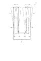
図面を参照して具体的に説明すると、図7において、特許文献3の音叉型水晶振動片1
は、基部2から延出する2本の互いに平行な振動腕3,4を備え、各振動腕3,4それぞ
れの中心線上に直線状の溝または孔6,7が設けられている。この音叉型水晶振動片1の
各振動腕3,4の両主面(溝または孔6,7形成面と同じ面)に設けられた図示しない励
振電極に所定の駆動電圧を印加すると、振動腕3,4は、図中想像線(二点鎖線)および
矢印で示すように、互いに接近または離反する向きに屈曲振動する。
Specifically, referring to the drawings, in FIG.
Comprises two mutually parallel vibrating
この屈曲振動によって、各振動腕3,4の基部2との付け根部の領域に機械的歪が発生
する。すなわち、振動腕3の基部2との付け根部においては、屈曲振動により圧縮応力ま
たは引張応力が作用する第1の領域10と、この第1の領域10に圧縮応力が作用する場
合は引張応力が作用し、第1の領域10に引張応力が作用する場合は圧縮応力が作用する
関係にある第2の領域11と、が存在し、これら第1の領域10および第2の領域11に
おいては、圧縮応力が作用したときには温度が上昇し、引張応力が作用したときには温度
が下降する。
これと同様に、振動腕4の基部2との付け根部においては、屈曲振動により圧縮応力ま
たは引張応力が作用する第1の領域12と、この第1の領域12に圧縮応力が作用する場
合は引張応力が作用し、第1の領域12に引張応力が作用する場合は圧縮応力が作用する
関係にある第2の領域13と、が存在し、第1の領域12および第2の領域13において
は、圧縮応力が作用したときに温度が上昇し、引張応力が作用したときには温度が下降す
る。
Due to this bending vibration, mechanical strain is generated in the region of the base portion of the vibrating
Similarly, at the base portion of the vibrating arm 4 with the
このようにして発生した温度勾配によって、各振動腕3,4の基部2との付け根部分の
内部には、第1の領域10,12と第2の領域11,13との間で熱伝導が発生する。温
度勾配は、各振動腕3,4の屈曲振動に対応して逆向きに発生し、それに対応して熱伝導
も逆向きとなる。この熱伝導によって、振動腕3,4の振動エネルギーは、その一部が振
動中も常に熱弾性損失として失われ、その結果、音叉型水晶振動片1のQ値が低下して振
動特性が不安定になり、所望の性能を実現することが困難になる。
特許文献3の音叉型水晶振動片1では、各振動腕3,4それぞれの中心線上に設けられ
た溝または孔6,7によって圧縮側から引っ張り側への熱移動が阻止されることにより、
熱弾性損失によるQ値の低下を防止または軽減することを可能としている。具体的には、
各振動腕3,4に設けられた溝または孔6,7に沿って屈曲振動体内を迂回することによ
り、熱伝導経路が長くなって熱緩和時間τが延長されるので、1/(2πτ)で求められ
る熱緩和周波数は、図8に示す曲線F1の緩和周波数f10に示すように、溝または孔6,
7を設けない従来の音叉型屈曲振動片の曲線Fおよびその緩和周波数f0に比して図中左
側にシフトする。
Due to the temperature gradient generated in this way, heat conduction is performed between the
In the tuning-fork type
It is possible to prevent or reduce a decrease in Q value due to thermoelastic loss. In particular,
By bypassing the flexural vibration body along the grooves or
The curve is shifted to the left side in the figure as compared with the curve F of the conventional tuning-fork type flexural vibrating
しかしながら、特許文献3に記載の音叉型水晶振動片1では、小型化が進むに従って、
溝または孔を形成することが困難になるとともに、溝または孔によって熱緩和時間を延長
する効果が少なくなりQ値の低下の抑制効果が十分に得られなくなるという課題があった
。
However, in the tuning fork type
There is a problem that it becomes difficult to form grooves or holes, and the effect of extending the thermal relaxation time is reduced by the grooves or holes, so that the effect of suppressing the decrease in Q value cannot be obtained sufficiently.
本発明は、上述の課題の少なくとも一部を解決するためになされたものであり、以下の
形態または適用例として実現することが可能である。
SUMMARY An advantage of some aspects of the invention is to solve at least a part of the problems described above, and the invention can be implemented as the following forms or application examples.
〔適用例1〕本適用例にかかる屈曲振動片は、振動により圧縮応力または引張応力が作
用する第1の領域と、前記第1の領域に圧縮応力が作用する場合は引張応力が作用し前記
第1の領域に引張応力が作用する場合は圧縮応力が作用する関係にある第2の領域と、を
有する屈曲振動体からなり、前記第1の領域と前記第2の領域の間に、前記屈曲振動体よ
りも高い熱伝導率を有する材料からなり前記第1の領域と前記第2の領域とを熱的に接続
する熱伝導路を有する屈曲振動片であって、前記熱伝導路の数をm、前記熱伝導路の熱抵
抗率をρth、前記屈曲振動体の熱抵抗率をρv、前記屈曲振動体の振動方向と直交する方
向の厚みをtv、前記熱伝導路の前記屈曲振動体の振動方向と直交する方向の厚みをtth
としたときに、tth≧(1/m)×tv×(ρth/ρv)の関係を満たすことを特徴とす
る。また、ある形態では、振動により圧縮応力または引張応力が作用する第1の領域と、
前記第1の領域に圧縮応力が作用する場合は引張応力が作用し前記第1の領域に引張応力
が作用する場合は圧縮応力が作用する関係にある第2の領域と、を有し、第1の面内で屈
曲振動する屈曲振動体と、前記第1の領域と前記第2の領域の間に、前記屈曲振動体より
も高い熱伝導率を有する材料からなり前記第1の領域と前記第2の領域とを熱的に接続す
る熱伝導路と、を有する屈曲振動片であって、前記熱伝導路の数をm、前記熱伝導路の熱
抵抗率をρth、前記屈曲振動体の熱抵抗率をρV、前記屈曲振動体の前記第1の面と直交
する方向の厚みをtv、前記熱伝導路の厚みをtthとしたときに、tth≧(1/m)×tv
×(ρth/ρv)の関係を満たすことを特徴とする。また、ある形態では、熱伝導路は屈
曲振動片の外面に形成されることを特徴とする。
[Application Example 1] The bending vibration piece according to this application example includes a first region where compressive stress or tensile stress is applied by vibration, and when compressive stress is applied to the first region, the tensile stress is applied. When a tensile stress is applied to the first region, the second region is in a relationship in which a compressive stress is applied, and between the first region and the second region, A bending vibration piece made of a material having a higher thermal conductivity than that of a bending vibrator and having a heat conduction path for thermally connecting the first region and the second region, the number of the heat conduction paths M , thermal resistivity of the thermal conduction path ρ th , thermal resistance of the flexural vibrator ρ v , thickness in a direction perpendicular to the vibration direction of the flexural vibrator, t v , The thickness in the direction orthogonal to the vibration direction of the flexural vibrator is expressed as t th
In this case, the relationship of t th ≧ (1 / m) × t v × (ρ th / ρv) is satisfied. Further, in one form, a first region where compressive stress or tensile stress acts by vibration,
A second region in which a tensile stress acts when the compressive stress acts on the first region and a compressive stress acts when the tensile stress acts on the first region; A bending vibration body that bends and vibrates in one plane, and is formed of a material having a higher thermal conductivity than the bending vibration body between the first region and the second region. A flexural vibration piece having a heat conduction path thermally connecting to the second region, wherein the number of the heat conduction paths is m, the thermal resistivity of the heat conduction paths is ρ th , and the flexural vibration body T th ≧ (1 / m) where ρ V is the thermal resistivity of the flexural vibrator, t v is the thickness of the flexural vibrator perpendicular to the first surface, and t th is the thickness of the heat conduction path. × t v
It is characterized by satisfying the relationship of x (ρ th / ρ v ). In one embodiment, the heat conduction path is formed on the outer surface of the bending vibration piece.
上記構成のように、屈曲振動体と熱伝導路との熱伝導係数の比、および、第1の領域か
ら第2の領域への熱伝導路の数に応じて熱伝導路の厚みを設定することにより、第1の領
域と第2の領域との間の熱伝導が熱伝導路を介して効率的に行われるようになることを本
願発明者は見出した。これにより、第1の領域と第2の領域との温度を平衡状態とするの
に要する熱緩和時間が短縮されるので、Q値の低下を抑えることができる。
また、上述した従来の対策のように屈曲振動体に孔や溝を形成する必要がないので、屈
曲振動片の小型化への対応が容易になる。
したがって、Q値の低下が抑えられ振動特性の安定した小型の屈曲振動片を提供するこ
とができる。
As in the above configuration, the thickness of the heat conduction path is set according to the ratio of the heat conduction coefficient between the flexural vibrator and the heat conduction path and the number of heat conduction paths from the first region to the second region. Thus, the inventor of the present application has found that heat conduction between the first region and the second region is efficiently performed through the heat conduction path. As a result, the thermal relaxation time required to bring the temperature of the first region and the second region into an equilibrium state is shortened, so that a decrease in Q value can be suppressed.
In addition, since it is not necessary to form holes or grooves in the bending vibration body as in the conventional measures described above, it is easy to cope with downsizing of the bending vibration piece.
Therefore, it is possible to provide a small flexural vibration piece that suppresses a decrease in the Q value and has stable vibration characteristics.
〔適用例2〕上記適用例にかかる屈曲振動片において、前記屈曲振動体の機械的な振動
周波数をfr、前記屈曲振動片の熱緩和周波数をf20、前記熱伝導路が設けられていない
状態の屈曲振動片の熱緩和周波数をf0としたときに、1>fr/(f0+(f20−f0)
/3)の関係を満たすことを特徴とする。また、ある形態では、屈曲振動体の機械的な振
動周波数をfr、前記屈曲振動片の熱緩和周波数をf20、円周率をπ、前記屈曲振動体に
用いた材料の振動方向の熱伝導率をk、前記屈曲振動体に用いた材料の質量密度をρ、前
記屈曲振動体に用いた材料の熱容量をCp、前記屈曲振動体の振動方向の幅をaとし、f0
=πk/(2ρCpa2)としたとき、1>fr/(f0+(f20−f0)/3)の関係を満
たすことを特徴とする。
Application Example 2 In the bending vibration piece according to the application example, the mechanical vibration frequency of the bending vibration member is fr, the thermal relaxation frequency of the bending vibration piece is f 20 , and the heat conduction path is not provided. the thermal relaxation frequency of the bending-vibration piece when the f 0, 1> fr / ( f 0 + (f 20 -f 0)
/ 3) is satisfied. In one embodiment, the mechanical vibration frequency of the flexural vibrator is fr, the thermal relaxation frequency of the flexural vibrator piece is f 20 , the circumference is π, and the heat conduction in the vibration direction of the material used for the flexural vibrator. The rate is k, the mass density of the material used for the flexural vibrator is ρ, the heat capacity of the material used for the flexural vibrator is C p , the width in the vibration direction of the flexural vibrator is a, and f 0
=? K / when the (2ρC p a 2), characterized by satisfying the relationship of 1> fr / (f 0 + (f 20 -f 0) / 3).
この構成によれば、従来構造の屈曲振動片よりもQ値が高く確保され、安定した振動特
性を有する屈曲振動片を提供することができる。
According to this configuration, it is possible to provide a bending vibration piece that has a Q value higher than that of a bending vibration piece having a conventional structure and has stable vibration characteristics.
〔適用例3〕上記適用例にかかる屈曲振動片において、前記屈曲振動体の機械的な振動
周波数をfr、円周率をπ、前記屈曲振動体に用いた材料の振動方向の熱伝導率をk、前
記屈曲振動体に用いた材料の質量密度をρ、前記屈曲振動体に用いた材料の熱容量をCp
、前記屈曲振動体の振動方向の幅をaとし、f0=πk/(2ρCpa2)としたとき、1
≧fr/f0であることを特徴とする。
Application Example 3 In the bending vibration piece according to the application example described above, the mechanical vibration frequency of the bending vibration body is fr, the circumferential ratio is π, and the thermal conductivity in the vibration direction of the material used for the bending vibration body is set. k, ρ is the mass density of the material used for the bending vibrator, and C p is the heat capacity of the material used for the bending vibrator.
When the vibration direction of the width of the flexural vibrator is a, and the f 0 = πk / (2ρC p a 2), 1
≧ fr / f 0 .
この構成によれば、高いQ値を確保し、安定した振動特性を有する屈曲振動片を提供す
ることが可能となる。
According to this configuration, it is possible to provide a bending vibration piece that ensures a high Q value and has stable vibration characteristics.
〔適用例4〕上記適用例にかかる屈曲振動片において、前記熱伝導路が屈曲振動体に形
成された励振電極の一部からなることを特徴とする。
Application Example 4 In the bending vibration piece according to the application example described above, the heat conduction path includes a part of an excitation electrode formed on the bending vibration member.
この構成によれば、励振電極を熱伝導路として用いているので、効率的に屈曲振動片を
製造することができる。
According to this configuration, since the excitation electrode is used as the heat conduction path, the flexural vibration piece can be efficiently manufactured.
〔適用例5〕上記適用例にかかる屈曲振動片において、前記熱伝導路が不導体材料から
なることを特徴とする。
Application Example 5 In the bending vibration piece according to the application example described above, the heat conduction path is made of a non-conductive material.
この構成によれば、励振電極などの電極との短絡を気にすることなく、それらの電極上
に熱伝導路を設けることも可能になるので、設計の自由度が増して小型化に有利となり、
また、製造も容易になる。
According to this configuration, it is possible to provide a heat conduction path on the electrodes without worrying about a short circuit with an excitation electrode or the like, which increases the degree of freedom in design and is advantageous for downsizing. ,
In addition, manufacturing is facilitated.
〔適用例6〕本適用例にかかる発振器は、上記適用例のいずれかに記載の屈曲振動片と
、該屈曲振動片を駆動させる発振回路とを少なくとも備えることを特徴とする。
Application Example 6 An oscillator according to this application example includes at least the bending vibration piece according to any one of the application examples described above and an oscillation circuit that drives the bending vibration piece.
この構成によれば、上記適用例に示すQ値の低下が抑制された屈曲振動片を備えている
ので、安定した発振特性を有する小型の発振器を提供することができる。
According to this configuration, since the bending vibration piece in which the decrease in the Q value shown in the application example is suppressed is provided, a small oscillator having stable oscillation characteristics can be provided.
以下、本発明の屈曲振動片を音叉型水晶振動片に具体化した一実施形態について図面を
参照しながら説明する。
Hereinafter, an embodiment in which a bending vibration piece of the present invention is embodied as a tuning fork type quartz vibration piece will be described with reference to the drawings.
(第1の実施形態)
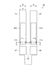
図1および図2は、第1の実施形態の屈曲振動片としての音叉型水晶振動片を模式的に
説明したものであり、図1は一方の主面側の平面図、図2は、図1のA−A線断面図であ
る。
図1において、本実施形態の音叉型水晶振動片50は、屈曲振動体材料を加工すること
により形成された基部52と、この基部52の一端側(図において上端側)から二股に別
れて互いに平行に延出する一対の振動腕53,54とからなる所謂音叉型の外形を有して
形成されている。屈曲振動体材料としては、本実施形態では従来の音叉型水晶振動片と同
様に、水晶の単結晶から切り出されたものを使用する。例えば、所謂Zカットの水晶薄板
から、水晶結晶軸のY軸を振動腕53,54の長手方向に、X軸をその幅方向に、Z軸を
振動片の表裏主面の垂直方向にそれぞれ配向して形成される。音叉型水晶振動片50の音
叉型の外形は、例えば水晶ウエハーなどの水晶基板材料をフッ酸溶液などでウエットエッ
チングしたり、ドライエッチングしたりすることにより精密に形成することができる。
(First embodiment)
FIGS. 1 and 2 schematically illustrate a tuning-fork type crystal vibrating piece as a bending vibrating piece according to the first embodiment. FIG. 1 is a plan view of one main surface side, and FIG. It is AA sectional view taken on the line of 1. FIG.
In FIG. 1, a tuning-fork type
なお、屈曲振動体材料として、上記の水晶以外の圧電基板を用いる構成であってもよい
。例えば、窒化アルミニウム(AlN)、ニオブ酸リチウム(LiNbO3)、タンタル
酸リチウム(LiTaO3)、チタン酸ジルコン酸鉛(PZT)、四ほう酸リチウム(L
i2B4O7)などの酸化物基板や、ガラス基板上に窒化アルミニウム、五酸化タンタル(
Ta2O5)などの薄膜圧電材料を積層させて構成された圧電基板を用いることができる。
また、圧電基板以外にも、例えばシリコン半導体材料などにより屈曲振動片を形成するこ
ともできる。
ただし、屈曲振動片の共振周波数は屈曲振動体材料のヤング率を質量密度で除した値の
平方根に比例し、ヤング率を質量密度で除した値が小さい材料ほど、屈曲振動片の小型化
に有利である。よって、本実施形態の音叉型水晶振動片50のように水晶からなる屈曲振
動片は、シリコン半導体材料などに比してヤング率を質量密度で除した値の平方根が小さ
くできるので小型化に有利であるとともに、周波数温度特性に優れているので、本実施形
態の屈曲振動片としての音叉型水晶振動片50に用いる材料として特に好ましい。
Note that a configuration using a piezoelectric substrate other than the above-described quartz may be used as the bending vibrator material. For example, aluminum nitride (AlN), lithium niobate (LiNbO 3 ), lithium tantalate (LiTaO 3 ), lead zirconate titanate (PZT), lithium tetraborate (L
i 2 B 4 O 7 ) or other oxide substrates, or glass substrates with aluminum nitride or tantalum pentoxide (
A piezoelectric substrate constructed by laminating thin film piezoelectric materials such as Ta 2 O 5 ) can be used.
In addition to the piezoelectric substrate, the bending vibration piece can be formed of, for example, a silicon semiconductor material.
However, the resonance frequency of the bending vibration piece is proportional to the square root of the value obtained by dividing the Young's modulus of the bending vibration material by the mass density, and the smaller the value obtained by dividing the Young's modulus by the mass density, the smaller the bending vibration piece. It is advantageous. Therefore, a flexural vibration piece made of crystal like the tuning fork type
各振動腕53,54の一方の主面には、励振電極36A,37Aが形成されている。ま
た、基部52の振動腕53,54が延出された一端側と異なる他端側近傍には、外部との
接続に供する外部接続電極66,67が設けられている。これらの外部接続電極66,6
7は、それぞれ励振電極36A,37Aと対応しており、それぞれ対応する電極同士が、
音叉型水晶振動片50の主面や側面に引き回されて設けられた図示しない引き回し配線に
より接続されている。
7 correspond to the
The tuning fork-type
同様に、図2に示すように、各振動腕53,54の他方の主面には、各振動腕53,5
4において各励振電極36A,37Aの対向電極としての励振電極36B,37Bがそれ
ぞれ設けられている。励振電極36B,37Bは、それぞれ対応する励振電極36A,3
7Aや外部接続電極66,67などの電極と、音叉型水晶振動片50の主面や側面に引き
回されて設けられた図示しない引き回し配線により接続されている。
ここで、振動腕53の励振電極36A,36Bは同電位であり、振動腕54の励振電極
37A,37Bは同電位である。また、各振動腕53,54の励振電極36A,36Bと
励振電極37A,37Bとは電位が異なる。
Similarly, as shown in FIG. 2, the other main surface of each vibrating
4,
7A and
Here, the
ここで、本実施形態の音叉型水晶振動片50では、励振電極36A,36B,37A,
37Bは、各振動腕53,54の基部52との付け根部分近傍の下記に詳述する第1の領
域110,112と第2の領域111,113とを熱的に接続する熱伝導路として用いる
ために、第1の領域110,112および第2の領域111,113にかかる範囲まで形
成されている。
なお、本実施形態の音叉型水晶振動片50の特徴をわかりやすく説明する便宜上図示を
省略したが、各振動腕53,54の励振電極36A,36B,37A,37Bが形成され
た両主面と直交する両側面には、それぞれの振動腕53,54の励振電極36A,36B
または励振電極37A,37Bとそれぞれ同電位の励振電極が形成されている。
Here, in the tuning-fork type
37B is used as a heat conduction path for thermally connecting the
In addition, although illustration was abbreviate | omitted for convenience in explaining the characteristics of the tuning fork type
Alternatively, excitation electrodes having the same potential as the
上記した電極や配線は、従来、水晶をエッチングして音叉型水晶振動片50の外形を形
成した後で、例えば、ニッケル(Ni)またはクロム(Cr)を下地層として、その上に
、蒸着またはスパッタリングにより例えば金(Au)による電極層を成膜し、その後フォ
トリソグラフィーを用いてパターニングすることにより形成することができる。ただし、
本実施形態の音叉型水晶振動片50では、上記したように、励振電極36A,36B,3
7A,37Bの一部を熱伝導路として用いる構成となっているので、下記に詳述するよう
に、熱抵抗率が十分に低く熱伝導路として有効な金属材料を選定して用いる。
Conventionally, the above-described electrodes and wirings are formed by etching a quartz crystal to form the outer shape of the tuning-fork type
In the tuning fork type
Since a part of 7A and 37B is used as a heat conduction path, a metal material having a sufficiently low thermal resistivity and effective as a heat conduction path is selected and used as described in detail below.
ここで、本実施形態の音叉型水晶振動片50の構成において特に要部となる熱伝導路に
ついて詳細に説明する。
図2は、図1の音叉型水晶振動片50のA−A線断面、すなわち、各振動腕53,5
4の基部52との付け根部近傍の断面を示している。本実施形態では、この各振動腕53
,54の基部(52)との付け根近傍の励振電極36A,36B,37A,37Bを、後
述する熱弾性損失を抑制してQ値の劣化を防止するための熱伝導路として用いる。ここで
、熱伝導路とは、図1に示す音叉型水晶振動片50において、矢印Gで示す各振動腕53
,54の屈曲振動方向に位置する基部52との付け根部分近傍の領域(二点鎖線で示す)
ある第1の領域110,112と第2の領域111,113との熱伝導経路を指す。
Here, the heat conduction path which is a main part in the configuration of the tuning fork type
2 is a cross-sectional view taken along line AA of the tuning-fork type
The cross section of the base part vicinity with 4
, 54 and
, 54 in the vicinity of the base portion with the base 52 located in the bending vibration direction (indicated by a two-dot chain line)
It refers to a heat conduction path between a certain
図2に戻り、振動腕53の基部(52)との付け根近傍において、振動腕53の一方の
主面に設けられた励振電極36Aは厚みt1を有している。また、振動腕53の他方の主
面に設けられた励振電極36Bは厚みt2を有している。
同様に、振動腕54の一方の主面に設けられた励振電極37Aは厚みt1を有し、他方
の主面に設けられた励振電極37Bは厚みt2を有している。ここで、本実施形態の音叉
型水晶振動片50においてはt1=t2となっている。
Returning to FIG. 2, the excitation electrode 36 </ b> A provided on one main surface of the vibrating
Similarly, the
本実施形態において熱伝導路として用いられる励振電極36A,36B,37A,37
Bの材料としては、少なくとも屈曲振動体材料である水晶よりも熱抵抗率が低い材料であ
って、なるべく低い熱抵抗率の材料が用いられ、この熱抵抗率の他に、入手が比較的容易
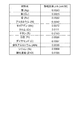
で低コストであることや、製造容易性などを勘案して選定する。例えば、図3に、熱伝導
路(本実施形態では励振電極の一部)に適用可能な材料の例を示す。この図3の材料の中
でもより熱抵抗率の低い材料を用いることが、熱伝導路の厚みを薄くすることができるの
で好ましい。また、本実施形態では、励振電極36A,36B,37A,37Bの一部を
熱伝導路として用いる構成としているので、電極となりうる導電体材料を用いる必要があ
ることは当然であり、図中の不導体物質であるダイヤモンドは適用外となる。ただし、後
述する他の実施例のように、励振電極などの電極とは別に熱伝導路を形成する場合には、
熱伝導路の材料に導電性は必要としないので、図中のダイヤモンドなどの比較的低い熱抵
抗率を有する非導電性の材料を適宜に用いることができる。
The material of B is a material having a thermal resistance lower than that of quartz, which is at least a bending vibration material, and a material having a thermal resistance as low as possible. In addition to this thermal resistivity, it is relatively easy to obtain. Therefore, it is selected considering the low cost and ease of manufacturing. For example, FIG. 3 shows an example of a material applicable to the heat conduction path (a part of the excitation electrode in this embodiment). It is preferable to use a material having a lower thermal resistivity among the materials shown in FIG. 3 because the thickness of the heat conduction path can be reduced. In the present embodiment, since a part of the
Since the material of the heat conduction path does not require conductivity, a non-conductive material having a relatively low thermal resistivity such as diamond in the figure can be used as appropriate.
上記構成において、屈曲振動体の熱伝導路の数をm、熱伝導路の熱抵抗率をρth、屈曲
振動体の熱抵抗率をρv、屈曲振動体の振動方向と直交する方向の厚みをtv、熱伝導路
の屈曲振動体の振動方向と直交する方向の厚みをtthとしたときに、tth≧(1/m)×
tv×(ρth/ρv)の関係を満たすことにより、後述するQ値の低下の抑制効果を奏する
ことを本願発明者は見出した。即ち、この条件を満たすことにより、熱伝導路としての励
振電極36A,36B,37A,37Bの一部よりも屈曲振動体(本実施形態では水晶)
の方が熱が伝わりやすい、という好ましくない状態を回避できる。好ましくは、tth>(
1/m)×tv×(ρth/ρv)であり、これにより、屈曲振動体(本実施形態では水晶)
よりも熱伝導路の方が熱が伝わりやすくなる状態を確実に実現することができ、熱緩和時
間を短くすることによるQ値の向上が確実に達成される。本実施形態において、前記厚み
tthが上記の励振電極36A,36B,37A,37Bの熱伝導路として用いる一部の厚
みt1および厚みt2になる。なお、熱伝導路の数mとは、上記第1の領域および第2の領
域を有する屈曲振動体ごとの第1の領域と第2の領域とを熱的に接続する熱伝導路の数を
指す。
In the above configuration, the number of heat conduction paths of the flexural vibrator m, the thermal resistance of the heat conduction path [rho th, the thermal resistivity [rho v of the flexural vibrator, the direction of thickness perpendicular to the direction of the bending vibration member the tv, the direction of thickness perpendicular to the vibration direction of the flexural vibration of the heat conduction path when the t th, t th ≧ (1 / m) ×
The inventor of the present application has found that, by satisfying the relationship of t v × (ρ th / ρ v ), the effect of suppressing the decrease in the Q value described later is exhibited. That is, by satisfying this condition, the bending vibration body (quartz in the present embodiment) rather than a part of the
It is possible to avoid an unfavorable state where heat is more easily transmitted. Preferably, t th > (
1 / m) × t v × (ρ th / ρ v ), whereby a flexural vibrator (crystal in the present embodiment)
It is possible to reliably realize a state in which heat is more easily transmitted in the heat conduction path than in the heat conduction path, and the Q value can be reliably improved by shortening the heat relaxation time. In the present embodiment, the thickness t th becomes a part of the thickness t 1 and thickness t 2 used as the heat conduction paths of the
例えば、本実施形態における熱伝導路の数mとは、各振動腕53,54毎に一方の主面
の励振電極36A,37A、および他方の主面の励振電極36B,37Bそれぞれの一部
が熱伝導路として用いられるので、熱伝導路の数mはm=2になる。
また、本実施形態の音叉型水晶振動片50において、屈曲振動体としての水晶基板にZ
カット水晶(熱抵抗率ρv=0.1613mK/W)を用いて、且つ、各振動腕53,5
4の振動方向と直交する方向の厚みtvを100μmとし、図3に示す材料のうち金(A
u、熱抵抗率ρth=0.0032mK/W)を用いて励振電極(熱伝導路)を形成する場
合、各励振電極36A,36B,37A,37Bの少なくとも熱伝導路として用いる部分
の厚みt1およびt2は、上記の式tth≧(1/m)×tv×(ρth/ρv)の関係を満たせ
ばよいので、t1またはt2は、それぞれ1μm以上とすればよい。
For example, the number m of heat conduction paths in the present embodiment means that for each vibrating
Further, in the tuning fork type
Using a cut crystal (thermal resistivity ρ v = 0.1613 mK / W) and the vibrating
4 in the direction of thickness t v perpendicular to the vibration direction and 100 [mu] m, of which gold material shown in FIG. 3 (A
u, the case of forming the excitation electrodes (thermal conduction path) using a thermal resistivity ρ th = 0.0032mK / W), each of the
なお、本実施形態では、図2に示すように厚みt1,t2に調整した各励振電極36A
,36B,37A,37Bの一部を熱伝導路として用いる構成を説明したが、各励振電極
36A,36B,37A,37Bのうち少なくとも熱伝導路として用いる部分の厚みを厚
みt1,t2に調整すればよい。例えば、励振電極形成工程に、熱伝導路として用いる部分
と異なる部分をマスキングして励振電極用の材料を堆積させる工程を含むことにより、電
極形成用材料を熱伝導路として用いる部分のみを厚づけして、その他の部分の電極形成用
材料の使用量を削減することができる。
In the present embodiment, each
, 36B, 37A, has been described a structure using a part of 37B as a heat conduction path, each of the
図1において、音叉型水晶振動片50に、外部に接続された励振手段としての発振回路
(図示せず)から励振電極36A,36Bおよび励振電極37A,37Bに駆動電圧を印
加すると、振動腕53,54は水平方向に、図中矢印Gで示すように互いに接近または離
反する向きに屈曲振動する。本実施形態では、基部52と振動腕53,54は所定の第1
の面上に形成され、第1の面内に屈曲振動するとも言える。
In FIG. 1, when a driving voltage is applied to the tuning fork type
It can be said that it is formed on the first surface and bends and vibrates in the first surface.
この屈曲振動によって、基部52と各振動腕53,54との連結部において、各振動腕
53,54の振動方向の付け根部分の領域には、圧縮応力と引張応力とが発生する。すな
わち、振動腕53の図中の第1の領域110および第2の領域111に圧縮応力と引張応
力とが発生し、これと同様に、振動腕54の基部52との連結部分の領域にも圧縮応力と
引張応力とが発生する(詳細は後述する)。図中の振動腕53側で詳述すると、振動腕5
3の自由端側が振動腕54に接近する向きに屈曲振動すると、振動腕53の第1の領域1
10には引張応力が作用して温度が下降し、第2の領域111には圧縮応力が作用して温
度が上昇する。逆に、振動腕53の自由端側が振動腕54から離反する向きに屈曲すると
、第1の領域110には圧縮応力が作用して温度が上昇し、第2の領域111には引張応
力が作用して温度が下降する。
Due to this bending vibration, compressive stress and tensile stress are generated in the region of the base portion in the vibration direction of each vibrating
3 is bent and vibrated in a direction approaching the vibrating
Tensile stress acts on 10 and the temperature falls, and compressive stress acts on the
同様に、振動腕54の自由端側が振動腕53に接近する向きに屈曲振動すると、振動腕
54の第1の領域112には引張応力が作用して温度が下降し、第2の領域113には圧
縮応力が作用して温度が上昇する。逆に、振動腕54の自由端側が振動腕53から離反す
る向きに屈曲すると、第1の領域112には圧縮応力が作用して温度が上昇し、第2の領
域113には引張応力が作用して温度が下降する。
このように、振動腕53,54それぞれの基部52との連結部の内部には、圧縮応力が
作用する部分と引張応力が作用する部分との間で温度勾配が生じ、その傾斜は、各振動腕
53,54の振動の向きによって逆向きになる。
Similarly, when the free end side of the vibrating
As described above, a temperature gradient is generated between the portion where the compressive stress is applied and the portion where the tensile stress is applied inside the connecting portion of each of the vibrating
この温度勾配によって、熱が、圧縮側の部分から引張(伸張)側の部分へ、すなわち、
高温側から低温側へと伝達される。本実施形態の音叉型水晶振動片50では、この圧縮側
の部分から伸張側の部分への熱の伝達が、各振動腕53,54の励振電極36A,36B
および励振電極37A,37Bの一部を熱伝導路として行われる。
図1に示す音叉型水晶振動片50の一方の主面側について詳細に説明すると、各振動腕
53,54にそれぞれ設けられた励振電極36A,37Aの一部(各振動腕53,54の
基部52との付け根部分近傍)は、各振動腕53,54の第1の領域110,112と第
2の領域111,113とを熱的に接続するように配置されている。ここで、励振電極3
6A,37Aの電極形成用の材料は、上記したように屈曲振動体としての水晶基板よりも
低い熱抵抗率を有しているので、第1の領域110,112と第2の領域111,113
との間の熱伝導は、励振電極36A,37Aの、第1の領域110,112および第2の
領域111,113を熱的に接続する領域を熱伝導路として行われる。
Due to this temperature gradient, heat is transferred from the compression part to the tension (elongation) part, that is,
It is transmitted from the high temperature side to the low temperature side. In the tuning fork type
The
1 will be described in detail. A part of the
Since the materials for forming
The heat conduction between the
このように、それらの一部を熱伝導路とする励振電極36A,36B,37A,37B
は、少なくとも屈曲振動体としての水晶よりも熱抵抗率が低い材料により構成され、且つ
、各振動腕53,54の振動方向と直交する方向の厚みtth(図2においてt1またはt2
)が、上記したようにtth≧(1/m)×tv×(ρth/ρv)の関係を満たすように調整
されている。これにより、屈曲振動片が第1の領域と第2の領域との熱伝導経路となる従
来構造の場合よりも圧縮側から伸張側への熱伝導時間が速くなる。すなわち、振動腕53
,54が屈曲振動したときの第1の領域110,112と第2の領域111,113との
間で温度が平衡状態になるまでの緩和時間τ1が、熱伝導路が無い従来構造の緩和時間τ0
よりも短くなる。すなわち、本実施形態の音叉型水晶振動片50の熱緩和周波数f20=1
/(2πτ1)において、τ1<τ0であるから、従来構造の音叉型水晶振動片の熱緩和周波
数f0=1/(2πτ0)よりも高くなる。
In this way, the
Is made of a material having a thermal resistance lower than that of quartz as at least a flexural vibrator, and has a thickness t th (t 1 or t 2 in FIG. 2) in a direction orthogonal to the vibration direction of each
) Is adjusted so as to satisfy the relationship of t th ≧ (1 / m) × t v × (ρ th / ρ v ) as described above. Thereby, the heat conduction time from the compression side to the expansion side becomes faster than in the case of the conventional structure in which the bending vibration piece serves as a heat conduction path between the first region and the second region. That is, the vibrating
, 54 when bending vibration occurs, the relaxation time τ 1 until the temperature reaches an equilibrium state between the
Shorter than. In other words, the tuning-fork type
In / (2πτ 1 ), τ 1 <τ 0 , so that it becomes higher than the thermal relaxation frequency f 0 = 1 / (2πτ 0 ) of the tuning-fork type crystal vibrating piece having the conventional structure.
一般に、熱緩和周波数f0は、下式(1)で求まることが知られている。
f0=πk/(2ρCpa2)…(1)
ここで、πは円周率、kは振動腕(屈曲振動体)の屈曲振動方向の熱伝導率、ρは振動
腕(屈曲振動体)の質量密度、Cpは振動腕(屈曲振動体)の熱容量、aは振動腕(屈曲
振動体)の屈曲振動方向の幅である。式(1)の熱伝導率k、質量密度ρ、熱容量Cpに
振動腕の材料そのものの定数を入力した場合、求まる熱緩和周波数f0は第1の領域11
0,112および第2の領域111,113を熱的に接続する熱伝導路を設けていない場
合の屈曲振動体の緩和振動周波数となる。
In general, the thermal relaxation frequency f 0 is known which is obtained by the following equation (1).
f 0 = πk / (2ρC p a 2) ... (1)
Here, π is the circumference ratio, k is the thermal conductivity of the vibrating arm (flexural vibrator) in the bending vibration direction, ρ is the mass density of the vibrating arm (flexural vibrator), and Cp is the vibration arm (flexural vibrator). The heat capacity, a, is the width of the vibrating arm (flexural vibrator) in the flexural vibration direction. When constants of the material of the vibrating arm itself are input to the thermal conductivity k, the mass density ρ, and the heat capacity Cp in the formula (1), the obtained thermal relaxation frequency f 0 is the
This is the relaxation vibration frequency of the flexural vibrator when no heat conduction path is provided to thermally connect 0, 112 and the
これを、図8の振動腕の機械的な振動周波数(共振周波数)とQ値との関係でみると、
曲線F自体の形状は変わらないから、熱緩和周波数の上昇に伴って、曲線Fが曲線F2の
位置まで周波数の上昇方向(紙面上右方向)にシフトしたことになる。したがって、振動
腕の機械的な振動周波数(共振周波数)をfrとしたときにfrが熱緩和周波数f0以下
となる範囲、すなわち1≧fr/f0を満たす範囲では、曲線F2におけるQ値は常に従来
構造の曲線Fよりも高くなる。加えて、曲線F2における、曲線Fと曲線F2の交点の周
波数より低い周波数帯、即ち1>fr/(f0+(f20−f0)/3)を満たす範囲におい
ても、従来構造の音叉型水晶振動片の曲線FにおけるQ値より高くなる。このように、本
実施形態の音叉型水晶振動片50は、各振動腕53,54それぞれの第1の領域110,
112と第2の領域111,113とを熱的に接続する熱伝導路(各励振電極36A,3
6B,37A,37Bの一部)が低い熱抵抗率を有して、且つ、厚みを管理して設けられ
ていることにより、Q値を改善して高性能化を実現することができる。
Looking at the relationship between the mechanical vibration frequency (resonance frequency) and the Q value of the vibrating arm in FIG.
Since the shape of the curve F itself does not change, the curve F is shifted to the position of the curve F2 in the frequency increasing direction (right direction on the paper) as the thermal relaxation frequency increases. Therefore, in the range where fr is equal to or less than the thermal relaxation frequency f 0 when the mechanical vibration frequency (resonance frequency) of the vibrating arm is fr, the Q value in the curve F2 is within a range satisfying 1 ≧ fr / f 0. It is always higher than the curve F of the conventional structure. In addition, in the curve F2, a frequency band lower than the frequency of intersection of the curve F and the curve F2, i.e. 1> fr / (f 0 + (f 20 -f 0) / 3) also in a range satisfying, tuning fork having a conventional structure Higher than the Q value in the curve F of the quartz crystal resonator element. As described above, the tuning-fork type
112 and the
6B, 37A, and 37B) have a low thermal resistivity and are provided with a controlled thickness, thereby improving the Q value and realizing high performance.
また、本実施形態では、励振電極36A,36B,37A,37Bの一部を熱伝導路と
して用いる構成としている。これにより、製造工程が簡略化され、また、スペース効率よ
くQ値の安定化対策を講じることができるので、音叉型水晶振動片50の小型化および低
コスト化に有利である。
In the present embodiment, a part of the
(第2の実施形態)
上記第1の実施形態では、音叉型水晶振動片50の励振電極36A,36B,37A,
37Bの一部を熱伝導路として用いる構成とした。これに限らず、屈曲振動体上に励振電
極とは別に熱伝導路を設ける構成としてもよい。
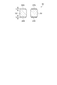
図4は、屈曲振動体上に励振電極とは別に熱伝導路を設けた音叉型水晶振動片を模式的
に説明するものであり、(a)は一主面側の平面図、(b)は(a)のB−B線断面図で
ある。なお、本変形例の図4において、上記第1の実施形態と同じ構成については同一符
号を付して説明を省略する。
(Second Embodiment)
In the first embodiment, the
A part of 37B was used as a heat conduction path. However, the present invention is not limited thereto, and a configuration in which a heat conduction path is provided on the flexural vibrator separately from the excitation electrode may be employed.
FIG. 4 schematically illustrates a tuning-fork type crystal vibrating piece in which a heat conduction path is provided separately from an excitation electrode on a flexural vibrator, (a) is a plan view on one main surface side, and (b). FIG. 3 is a sectional view taken along line BB in FIG. Note that, in FIG. 4 of this modification, the same components as those in the first embodiment are denoted by the same reference numerals, and description thereof is omitted.
図4(a)において、本変形例の音叉型水晶振動片150は、屈曲振動体材料からなる
基部52と、その基部52の一端側から二股に別れて互いに平行に延出する一対の振動腕
53,54とからなる音叉型の外形を有し、各振動腕53,54の一方の主面には励振電
極136A,137Aが形成されている。また、基部52の振動腕53,54が延出され
た一端側と異なる他端側近傍には外部接続電極66,67が設けられている。これらの外
部接続電極66,67は、それぞれ励振電極136A,137Aと対応しており、それぞ
れ対応する電極同士が、音叉型水晶振動片150の主面や側面に引き回されて設けられた
図示しない引き回し配線により接続されている。
なお、図示を省略したが、各振動腕53,54の励振電極36A,36B,37A,3
7Bが形成された両主面と直交する両側面には、それぞれの振動腕53,54の励振電極
36A,36Bまたは励振電極37A,37Bとそれぞれ同電位の励振電極が形成されて
いる。
4A, a tuning-fork type
Although not shown, the
Excitation electrodes having the same potential as the
振動腕53の励振電極136Aが形成された一方の主面側において、振動腕53の基部
52との付け根近傍には、上記第1の実施形態で説明した第1の領域と第2の領域(図1
を参照)とを熱的に接続する位置に、屈曲振動体としての水晶基板よりも熱抵抗率の低い
材料(図3を参照)からなる熱伝導路56Aが設けられている。
同様に、振動腕54の励振電極137Aが形成された一方の主面側においても、振動腕
54の基部52との付け根近傍に、上記第1の領域と上記第2の領域とを熱的に接続する
位置に熱伝導路57Aが設けられている。
On one main surface side where the excitation electrode 136 </ b> A of the vibrating
The
Similarly, also on one main surface side of the vibrating
また、図4(b)に示すように、振動腕53の他方の主面側においても、上記熱伝導路
56Aと対向する位置に熱伝導路56Bが設けられている。
ここで、振動腕53の両主面に設けられた熱伝導路56A,56Bは、上記第1の実施
形態で説明した熱伝導路の厚みtthと同じ定義の厚みt11,t12(第1の実施形態ではt
1=t2)に調整されて形成されている。
これと同様に、振動腕54の他方の主面側においても、厚みt11を有する上記熱伝導路
57Aと対向する位置に、厚みt12を有する熱伝導路(図示せず)が設けられている。
As shown in FIG. 4B, a
Here, the
1 = t 2 ).
Similarly, also in the other main surface side of the
上記構成によれば、励振電極136A,137Aなどの電極材料としての機能を考慮す
る必要がなく、熱伝導路56A,56B,57Aとして用いる材料の選択肢が広がるので
、より効果的に音叉型水晶振動片150のQ値の安定化や製造効率の向上を図ることが可
能になる。例えば、比較的厚い厚みで形成される熱伝導路56A,56B,57Aを、励
振電極136A,137Aの厚みに関係なく熱伝導路56A,56B,57Aの厚みだけ
を制御して形成すればよいので、材料の無駄が抑えられるとともに厚みの制御を精度よく
行うことができる。
また、励振電極136A,137Aとは別個に形成される熱伝導路56A,56B,5
7Aは導電性を必要としないので、例えば、図3に示す材料のうち、ダイヤモンドなどの
熱抵抗率の低い不導体材料を選択してQ値の低下をより効果的に抑えることができる。
According to the above configuration, it is not necessary to consider the function as the electrode material such as the
Further, the
Since 7A does not require electrical conductivity, for example, a non-conductive material with a low thermal resistivity such as diamond can be selected from the materials shown in FIG.
上記実施形態で説明した屈曲振動片としての音叉型水晶振動片は、以下の変形例として
実施することも可能である。
The tuning-fork type crystal vibrating piece as the bending vibrating piece described in the above embodiment can also be implemented as the following modifications.
(変形例)
上記第2の実施形態の音叉型水晶振動片150において、熱伝導路56A,56B,5
7Aは励振電極136A,137Aなどの電極と重ならない位置に設ける構成としたが、
熱伝導路の形成用材料として不導体材料を用いれば、熱伝導路を電極と重ねて設けること
も可能となり、小型化が図れるなどの効果を奏する。
図5は、変形例の音叉型水晶振動片を模式的に説明するものであり、図5(a)は一主
面側の平面図、(b)は(a)のC−C線断面図である。
(Modification)
In the tuning-fork type
7A is provided at a position where it does not overlap with electrodes such as
If a non-conductive material is used as the material for forming the heat conduction path, it is possible to provide the heat conduction path so as to overlap the electrode, and there is an effect such as miniaturization.
FIGS. 5A and 5B schematically illustrate a tuning-fork type crystal vibrating piece according to a modification. FIG. 5A is a plan view of one main surface side, and FIG. 5B is a cross-sectional view taken along the line CC in FIG. It is.
図5(a)において、本変形例の音叉型水晶振動片250は、屈曲振動体材料からなる
基部52と、その基部52の一端側から二股に別れて互いに平行に延出する一対の振動腕
53,54とからなる音叉型の外形を有している。また、各振動腕53,54の一方の主
面には、各振動腕53,54の基部52との付け根部分近傍を含む領域に設けられた励振
電極236A,237Aが形成されている。
5A, a tuning-fork type
振動腕53の励振電極236Aが形成された一方の主面側において、振動腕53の基部
52との付け根近傍の、上記第1の実施形態で説明した第1の領域と第2の領域(図1を
参照)とを熱的に接続する位置には、屈曲振動体としての水晶基板よりも熱抵抗率の低い
材料(例えば、図3を参照)のうち、不導体からなる熱伝導路156Aが設けられている
。熱伝導路156Aは、励振電極236A上を含む領域に設けられているが、不導体なの
で短絡などの電気的な不具合を回避できる。
同様に、振動腕54の励振電極237Aが形成された一方の主面側においても、振動腕
54の基部52との付け根近傍に、上記第1の領域と上記第2の領域とを熱的に接続する
位置に熱伝導路157Aが設けられている。
The first region and the second region described in the first embodiment in the vicinity of the base with the
Similarly, also on one main surface side of the vibrating
また、図5(b)に示すように、振動腕53の他方の主面側においても、上記熱伝導路
156Aと対向する位置に熱伝導路156Bが設けられている。
ここで、振動腕53の両主面に設けられた熱伝導路156A,156Bは、上記第1の
実施形態で説明した熱伝導路の厚みtthと同じ定義の厚みt21,t22(ここでt21=t22
)に調整されて形成されている。
これと同様に、振動腕54の他方の主面側においても、厚みt21を有する上記熱伝導路
157Aと対向する位置に、厚みt22を有する熱伝導路(図示せず)が設けられている。
なお、図示を省略したが、各振動腕53,54の励振電極236A,236B,237
A,237Bが形成された両主面と直交する両側面には、それぞれの振動腕53,54の
励振電極236A,236Bまたは励振電極237A,237Bとそれぞれ同電位の励振
電極が形成されている。
Further, as shown in FIG. 5B, a
Here, the
) To be formed.
Similarly, on the other main surface side of the vibrating
Although not shown, the
Excitation electrodes having the same potential as the
上記構成によれば、励振電極236A,236B,237Aなどの電極との短絡を気に
することなく、それらの電極上に熱伝導路156A,156B,157Aを設けることが
できるので、設計の自由度が増して小型化に有利である。また、電極と熱伝導路156A
,156B,157Aとの形成位置精度を緩くすることができるなど製造も容易になる。
According to the above configuration, the
, 156B, and 157A, the manufacturing position can be loosened, and the manufacturing becomes easy.
〔発振器〕
上記第1の実施形態および変形例で説明した屈曲振動片としての音叉型水晶振動片50
,150,250は、圧電デバイスや、圧電デバイス以外の様々な電子部品に適用するこ
とができる。特に、上記パッケージ内に上記の音叉型水晶振動片50,150,250の
うちいずれかの屈曲振動片とともに、その屈曲振動片を発振させる発振回路素子が少なく
とも組み込まれて構成された発振器は、Q値が改善されて高性能化が実現されるとともに
小型化を図ることができる。
[Oscillator]
The tuning-fork type
, 150, 250 can be applied to piezoelectric devices and various electronic components other than piezoelectric devices. In particular, an oscillator configured by incorporating at least an oscillation circuit element that oscillates one of the above-mentioned tuning-fork type
以上、発明者によってなされた本発明の実施の形態について具体的に説明したが、本発
明は上記した実施の形態に限定されるものではなく、その要旨を逸脱しない範囲で種々の
変更を加えることが可能である。
The embodiment of the present invention made by the inventor has been specifically described above, but the present invention is not limited to the above-described embodiment, and various modifications are made without departing from the scope of the present invention. Is possible.
例えば、上記第1の実施形態、第2の実施形態、および変形例の音叉型水晶振動片50
,150,250では、各振動腕53,54の両主面に熱伝導路56,57,156,1
57を設けた。すなわち、上記第1の実施形態で説明した熱伝導路56,57の厚みtth
(t1,t2)を規定する式tth≧(1/m)×tv×(ρth/ρv)において、熱伝導路の
数m=2としたが、これに限らない。熱伝導路は、屈曲振動体(音叉型水晶振動片の振動
腕)ごとに一つ、または三つであっても、上式の関係を満たすように各熱伝導経路の厚み
を確保すればよい。
For example, the tuning-fork type
, 150, 250,
57 was provided. That is, the thickness t th of the heat conduction paths 56 and 57 described in the first embodiment.
In the expression t th ≧ (1 / m) × t v × (ρ th / ρ v ) that defines (t 1 , t 2 ), the number m = 2 of heat conduction paths is used, but the present invention is not limited to this. Even if the number of heat conduction paths is one or three for each flexural vibrator (vibrating arm of a tuning-fork type crystal vibrating piece), the thickness of each heat conduction path may be ensured so as to satisfy the relationship of the above formula. .
また、上記第1の実施形態および変形例では、屈曲振動片としての音叉型水晶振動片5
0,150,250について説明した。これに限らず、本発明の屈曲振動片は、短冊状の
所謂ビーム型の屈曲振動片でもよく、また、三つ以上の振動腕を有する屈曲振動片であっ
ても、上記した第1の実施形態および変形例と同様な効果を得ることができる。
In the first embodiment and the modification, the tuning-fork type crystal vibrating piece 5 as a bending vibrating piece is used.
0, 150 and 250 have been described. The present invention is not limited to this, and the bending vibration piece of the present invention may be a so-called beam-shaped bending vibration piece or a bending vibration piece having three or more vibrating arms. Effects similar to those of the embodiment and the modification can be obtained.
三つ以上の振動腕を有する屈曲振動片の具体例を以下で説明する。図6は、三つの振動
腕を有する屈曲振動片の概略構成図であり、(a)〜(c)は電極形成の過程を示した斜
視図、(d)は(a)のA−A’断面図、(e)は(b)のB−B’断面図、(f)は(
c)のC−C’断面図である。
図6に示すように、圧電体素子10は、水晶基板からなる基部16とその一端から延出
する3本の振動腕18a,18b,18cを備え、振動腕18a,18b,18cは主面
12上に配置された下部電極20と、下部電極20上に配置された圧電膜22と、圧電膜
22上に配置された上部電極26と、を含み、振動腕18a,18cと振動腕18bとを
互い違いに上下に屈曲振動させる。換言すれば、基部16と振動腕18a,18b,18
bが形成された面と直交する方向に屈曲振動するとも言える。なお、本例の振動腕の振動
方向の幅aは、振動腕の厚み方向となる。
A specific example of a flexural vibration piece having three or more vibrating arms will be described below. FIG. 6 is a schematic configuration diagram of a bending vibration piece having three vibrating arms, in which (a) to (c) are perspective views showing a process of electrode formation, and (d) is an AA ′ line in (a). Sectional view, (e) is a sectional view taken along line BB ′ of (b), and (f) is (
It is CC 'sectional drawing of c).
As shown in FIG. 6, the
It can also be said that bending vibration occurs in a direction perpendicular to the surface on which b is formed. The width a in the vibration direction of the vibrating arm in this example is the thickness direction of the vibrating arm.
本例では、図6(a)、(d)に示すように、まず振動腕18a,18b,18cの外
面を覆うように下部電極20を形成する。次に図6(b)、(e)に示すように下部電極
20および基部16の一部を覆うように圧電膜22を形成すると共に下部電極20と上部
電極26とを導通接続するための開口部24を形成する。次に図6(c)、(f)に示す
ように圧電膜22上に上部電極26を形成する。このとき、振動腕18a,18cの下部
電極20と振動腕18bの上部電極26とが接続され、振動腕18a,18cの上部電極
26と振動腕18bの下部電極20とが接続される。本実施例においては、下部電極20
を水晶基板よりも高い熱伝導率を有した電極材料から形成する。
In this example, as shown in FIGS. 6A and 6D, first, the
Is formed from an electrode material having a higher thermal conductivity than the quartz substrate.
この屈曲振動によって、基部16と振動腕18a,18b,18cとの連結部において
、振動腕18a,18b,18cの振動方向の付け根部分の表裏面には、圧縮応力と引張
応力とが発生する。図中の振動腕で詳述すると、振動腕18a,18cが+Z軸方向に屈
曲振動すると、振動腕18a,18cの表面の第1の領域には圧縮応力が作用して温度が
上昇し、裏面の第2の領域には引張応力が作用して温度が下降する。一方、振動腕18b
は−Z軸方向に屈曲振動し、振動腕18bの表面の第1の領域には引張応力が作用して温
度が下降し、裏面の第2の領域には圧縮応力が作用して温度が上昇する。このように、振
動腕18a,18b,18cそれぞれの基部16との連結部の内部には、圧縮応力が作用
する部分と引張応力が作用する部分との間で温度勾配が生じ、その傾斜は、振動腕18a
,18b,18cの振動の向きによって逆向きになる。この温度勾配によって、熱が圧縮
側の部分から引張側の部分へ、すなわち、高温側から低温側へと伝達される。本実施形態
の音叉型水晶振動片では、この圧縮側の部分から伸張側の部分への熱の伝達が、振動腕1
8a,18b,18cの表面に形成した下部電極20の一部を熱伝導路として用いる。
Due to this bending vibration, compressive stress and tensile stress are generated on the front and back surfaces of the base portion in the vibration direction of the vibrating
Bends and vibrates in the −Z-axis direction, tensile stress acts on the first region of the surface of the vibrating
, 18b, 18c depending on the vibration direction. Due to this temperature gradient, heat is transferred from the compression side portion to the tension side portion, that is, from the high temperature side to the low temperature side. In the tuning-fork type crystal vibrating piece of the present embodiment, the heat transfer from the compression side portion to the extension side portion is the
A part of the
なお、本実施例では圧電膜または上部電極を振動腕の表面のみに形成しているが、下部
電極と同様に圧電膜または上部電極を振動腕の外面全体に形成し、圧電膜または上部電極
を熱伝導路として用いても良い。
In this embodiment, the piezoelectric film or the upper electrode is formed only on the surface of the vibrating arm. However, like the lower electrode, the piezoelectric film or the upper electrode is formed on the entire outer surface of the vibrating arm, and the piezoelectric film or the upper electrode is formed. It may be used as a heat conduction path.
また、上記第1の実施形態および変形例では、屈曲振動片の一例として、水晶からなる
音叉型水晶振動片50,150,250について説明したが、水晶以外の圧電基板からな
る屈曲振動片であってもよい。
また、屈曲振動片の基材は材料からなる圧電基板に限らない。圧電基板を用いた圧電駆
動型のもの以外に、静電気力を用いた静電駆動型や、磁気を用いた磁気駆動型の屈曲振動
片においても、本発明の構成およびその効果を発揮させることができる。
In the first embodiment and the modification, the tuning-fork type
The base material of the bending vibration piece is not limited to a piezoelectric substrate made of a material. In addition to the piezoelectric drive type using a piezoelectric substrate, the electrostatic drive type using electrostatic force and the magnetic drive type bending vibration piece using magnetism can also exert the configuration and effects of the present invention. it can.
1,50,150,250…屈曲振動片としての音叉型水晶振動片、2,52…基部、
3,4,53,54…振動腕、6,7…孔、10,12,110,112…第1の領域、
11,13,111,113…第2の領域、36A,36B,37A,37B,136A
,137A,236A,236B,237A…励振電極、56A,56B,156A,1
56B,157A…熱伝導路、66,67…外部接続電極。
1, 50, 150, 250 ... tuning-fork type quartz vibrating piece as bending vibrating piece, 2, 52 ... base,
3, 4, 53, 54 ... vibrating arm, 6, 7 ... hole, 10, 12, 110, 112 ... first region,
11, 13, 111, 113 ... 2nd area | region, 36A, 36B, 37A, 37B, 136A
, 137A, 236A, 236B, 237A ... excitation electrodes, 56A, 56B, 156A, 1
56B, 157A ... heat conduction path, 66, 67 ... external connection electrodes.
Claims (7)
力が作用する場合は引張応力が作用し前記第1の領域に引張応力が作用する場合は圧縮応
力が作用する関係にある第2の領域と、を有し、第1の面内で屈曲振動する屈曲振動体と
、
前記第1の領域と前記第2の領域の間に、前記屈曲振動体よりも高い熱伝導率を有する
材料からなり前記第1の領域と前記第2の領域とを熱的に接続する熱伝導路と、を有する
屈曲振動片であって、
前記熱伝導路の数をm、前記熱伝導路の熱抵抗率をρth、前記屈曲振動体の熱抵抗率を
ρV、前記屈曲振動体の前記第1の面と直交する方向の厚みをtv、前記熱伝導路の厚みを
tthとしたときに、tth≧(1/m)×tv×(ρth/ρv)の関係を満たすことを特徴と
する屈曲振動片。 A first region where compressive stress or tensile stress is applied by vibration, and a compressive stress is applied when compressive stress is applied to the first region, and a compressive stress is applied when tensile stress is applied to the first region. A second region in an acting relationship, and a flexural vibrator that flexurally vibrates in the first plane;
Thermal conduction for thermally connecting the first region and the second region, which is made of a material having a higher thermal conductivity than the flexural vibrator, between the first region and the second region. A flexural vibration piece having a path,
The number of the heat conduction paths is m, the thermal resistivity of the heat conduction paths is ρ th , the thermal resistance of the flexural vibrator is ρ V , and the thickness of the flexural vibrator is perpendicular to the first surface. t v, the thickness of the heat conduction path when the t th, t th ≧ (1 / m) × t v × (ρ th / ρ v) bending vibration piece, characterized in that satisfies the relationship.
前記熱伝導路は屈曲振動片の外面に形成されることを特徴とする屈曲振動片。 The bending vibration piece according to claim 1,
The bending vibration piece, wherein the heat conduction path is formed on an outer surface of the bending vibration piece.
前記屈曲振動体の機械的な振動周波数をfr、前記屈曲振動片の熱緩和周波数をf20、
円周率をπ、前記屈曲振動体に用いた材料の振動方向の熱伝導率をk、前記屈曲振動体に
用いた材料の質量密度をρ、前記屈曲振動体に用いた材料の熱容量をCp、前記屈曲振動
体の振動方向の幅をaとし、f0=πk/(2ρCpa2)としたとき、1>fr/(f0+
(f20−f0)/3)の関係を満たすことを特徴とする屈曲振動片。 The bending vibration piece according to claim 1 or 2,
The mechanical vibration frequency of the bending vibration body is fr, the thermal relaxation frequency of the bending vibration piece is f 20 ,
The circularity is π, the thermal conductivity in the vibration direction of the material used for the bending vibrator is k, the mass density of the material used for the bending vibrator is ρ, and the heat capacity of the material used for the bending vibrator is C. p, wherein the vibration direction of the width of the flexural vibrator is a, when the f 0 = πk / (2ρC p a 2), 1> fr / (f 0 +
A flexural vibration piece characterized by satisfying the relationship (f 20 -f 0 ) / 3).
前記屈曲振動体の機械的な振動周波数をfr、円周率をπ、前記屈曲振動体に用いた材
料の振動方向の熱伝導率をk、前記屈曲振動体に用いた材料の質量密度をρ、前記屈曲振
動体に用いた材料の熱容量をCp、前記屈曲振動体の振動方向の幅をaとし、f0=πk/
(2ρCpa2)としたとき、1≧fr/f0であることを特徴とする屈曲振動片。 The bending vibration piece according to claim 1 or 2,
The mechanical vibration frequency of the bending vibration body is fr, the circumferential ratio is π, the thermal conductivity in the vibration direction of the material used for the bending vibration body is k, and the mass density of the material used for the bending vibration body is ρ. the heat capacity of the material used for the flexural vibrator C p, the vibration direction of the width of the flexural vibrator and a, f 0 = πk /
When the (2ρC p a 2), bending vibration piece, which is a 1 ≧ fr / f 0.
前記熱伝導路が屈曲振動体に形成された励振電極の一部からなることを特徴とする屈曲
振動片。 In the bending vibration piece according to any one of claims 1 to 4,
A bending vibration piece, wherein the heat conduction path is formed of a part of an excitation electrode formed on a bending vibration member.
前記熱伝導路が不導体材料からなることを特徴とする屈曲振動片。 In the bending vibration piece according to any one of claims 1 to 4,
The bending vibration piece, wherein the heat conduction path is made of a non-conductive material.
該屈曲振動片を駆動させる発振回路とを少なくとも備えることを特徴とする発振器。 The bending vibration piece according to any one of claims 1 to 6,
An oscillator comprising at least an oscillation circuit for driving the bending vibration piece.
Priority Applications (3)
| Application Number | Priority Date | Filing Date | Title |
|---|---|---|---|
| JP2010002669A JP2010252302A (en) | 2009-03-25 | 2010-01-08 | Bending vibrator piece and oscillator using the same |
| US12/729,759 US8362854B2 (en) | 2009-03-25 | 2010-03-23 | Flexural vibration piece and oscillator using the same |
| CN2010101483190A CN101847978B (en) | 2009-03-25 | 2010-03-25 | Flexural vibration piece and oscillator using the same |
Applications Claiming Priority (2)
| Application Number | Priority Date | Filing Date | Title |
|---|---|---|---|
| JP2009073739 | 2009-03-25 | ||
| JP2010002669A JP2010252302A (en) | 2009-03-25 | 2010-01-08 | Bending vibrator piece and oscillator using the same |
Publications (2)
| Publication Number | Publication Date |
|---|---|
| JP2010252302A true JP2010252302A (en) | 2010-11-04 |
| JP2010252302A5 JP2010252302A5 (en) | 2013-02-14 |
Family
ID=42772462
Family Applications (1)
| Application Number | Title | Priority Date | Filing Date |
|---|---|---|---|
| JP2010002669A Withdrawn JP2010252302A (en) | 2009-03-25 | 2010-01-08 | Bending vibrator piece and oscillator using the same |
Country Status (3)
| Country | Link |
|---|---|
| US (1) | US8362854B2 (en) |
| JP (1) | JP2010252302A (en) |
| CN (1) | CN101847978B (en) |
Cited By (10)
| Publication number | Priority date | Publication date | Assignee | Title |
|---|---|---|---|---|
| US8482358B2 (en) | 2010-07-09 | 2013-07-09 | Seiko Epson Corporation | Flexural resonator element, resonator, oscillator, and electronic device |
| US8525606B2 (en) | 2011-02-02 | 2013-09-03 | Seiko Epson Corporation | Vibrator element, vibrator, oscillator, and electronic device |
| US8581669B2 (en) | 2011-02-02 | 2013-11-12 | Seiko Epson Corporation | Vibrator element, vibrator, oscillator, and electronic apparatus |
| US8760235B2 (en) | 2010-07-09 | 2014-06-24 | Seiko Epson Corporation | Resonator element, resonator, and oscillator |
| US8816572B2 (en) | 2010-04-08 | 2014-08-26 | Seiko Epson Corporation | Resonator element and resonator having a tapered arm next to the base |
| US9354128B2 (en) | 2013-12-27 | 2016-05-31 | Seiko Epson Corporation | Resonator element, resonator, oscillator, electronic apparatus, sensor, and mobile object |
| US9461615B2 (en) | 2013-07-19 | 2016-10-04 | Seiko Epson Corporation | Vibrator element, vibrator, oscillator, electronic apparatus, and moving object |
| US9705472B2 (en) | 2013-06-24 | 2017-07-11 | Seiko Epson Corporation | Resonator element, resonator, electronic device, electronic apparatus, and moving object |
| JP2018160802A (en) * | 2017-03-23 | 2018-10-11 | セイコーエプソン株式会社 | Vibration element, electronic device, electronic apparatus, and mobile body |
| WO2019059187A1 (en) * | 2017-09-21 | 2019-03-28 | 住友精密工業株式会社 | Angular speed sensor |
Families Citing this family (6)
| Publication number | Priority date | Publication date | Assignee | Title |
|---|---|---|---|---|
| WO2014185282A1 (en) * | 2013-05-13 | 2014-11-20 | 株式会社村田製作所 | Vibrating device |
| SG11201508861WA (en) | 2013-05-13 | 2015-11-27 | Murata Manufacturing Co | Vibrating device |
| CN107453649B (en) * | 2017-08-17 | 2023-06-16 | 浙江师范大学 | Vehicle-mounted energy harvester with unidirectionally bent piezoelectric vibrator |
| DE102017130527A1 (en) * | 2017-12-19 | 2019-06-19 | Endress+Hauser SE+Co. KG | Vibronic sensor |
| US10797681B1 (en) * | 2019-07-25 | 2020-10-06 | Zhuhai Crystal Resonance Technologies Co., Ltd. | Method of fabricating novel packages for electronic components |
| JP2022086056A (en) * | 2020-11-30 | 2022-06-09 | エスアイアイ・クリスタルテクノロジー株式会社 | Piezoelectric vibration piece, piezoelectric vibrator, oscillator, and manufacturing method of piezoelectric vibration pieces |
Citations (1)
| Publication number | Priority date | Publication date | Assignee | Title |
|---|---|---|---|---|
| JPH07139953A (en) * | 1993-11-19 | 1995-06-02 | Toyota Central Res & Dev Lab Inc | Method for adjusting frequency of angular-velocity detecting element and angular-velocity detecting element |
Family Cites Families (10)
| Publication number | Priority date | Publication date | Assignee | Title |
|---|---|---|---|---|
| JPH0232229U (en) | 1988-08-23 | 1990-02-28 | ||
| JP2002261575A (en) | 2000-12-25 | 2002-09-13 | Seiko Epson Corp | Vibrating piece, vibrator, oscillator and electronic equipment |
| EP1788702A3 (en) * | 2000-12-25 | 2008-01-16 | Seiko Epson Corporation | Vibrating piece, vibrator, oscillator, and electronic equipment |
| JP2004260718A (en) | 2003-02-27 | 2004-09-16 | Seiko Epson Corp | Tuning fork type vibration pieces, manufacturing method of tuning fork type vibration pieces, and piezoelectric device |
| JP4301200B2 (en) * | 2004-10-20 | 2009-07-22 | セイコーエプソン株式会社 | Piezoelectric vibrating piece and piezoelectric device |
| JP4277818B2 (en) * | 2005-03-22 | 2009-06-10 | セイコーエプソン株式会社 | Piezoelectric vibrating piece and piezoelectric device |
| CH700716B1 (en) | 2006-10-09 | 2010-10-15 | Suisse Electronique Microtech | Tuning fork resonator type silicon. |
| US8067880B2 (en) * | 2008-12-27 | 2011-11-29 | Seiko Epson Corporation | Flexural vibration element and electronic component |
| JP5446839B2 (en) * | 2009-02-17 | 2014-03-19 | セイコーエプソン株式会社 | Vibrating piece and vibrator |
| JP2010252303A (en) * | 2009-03-25 | 2010-11-04 | Seiko Epson Corp | Bending vibrator piece and oscillator using the same |
-
2010
- 2010-01-08 JP JP2010002669A patent/JP2010252302A/en not_active Withdrawn
- 2010-03-23 US US12/729,759 patent/US8362854B2/en not_active Expired - Fee Related
- 2010-03-25 CN CN2010101483190A patent/CN101847978B/en not_active Expired - Fee Related
Patent Citations (1)
| Publication number | Priority date | Publication date | Assignee | Title |
|---|---|---|---|---|
| JPH07139953A (en) * | 1993-11-19 | 1995-06-02 | Toyota Central Res & Dev Lab Inc | Method for adjusting frequency of angular-velocity detecting element and angular-velocity detecting element |
Cited By (16)
| Publication number | Priority date | Publication date | Assignee | Title |
|---|---|---|---|---|
| US8816572B2 (en) | 2010-04-08 | 2014-08-26 | Seiko Epson Corporation | Resonator element and resonator having a tapered arm next to the base |
| US9257961B2 (en) | 2010-04-08 | 2016-02-09 | Seiko Epson Corporation | Resonator element and resonator having a tapered arm next to the base |
| US9252741B2 (en) | 2010-04-08 | 2016-02-02 | Seiko Epson Corporation | Resonator element and resonator having a tapered arm next to the base |
| US9325278B2 (en) | 2010-07-09 | 2016-04-26 | Seiko Epson Corporation | Resonator element, resonator, and oscillator |
| US8760235B2 (en) | 2010-07-09 | 2014-06-24 | Seiko Epson Corporation | Resonator element, resonator, and oscillator |
| US9166554B2 (en) | 2010-07-09 | 2015-10-20 | Seiko Epson Corporation | Flexural resonator element, resonator, oscillator, and electronic device |
| US8482358B2 (en) | 2010-07-09 | 2013-07-09 | Seiko Epson Corporation | Flexural resonator element, resonator, oscillator, and electronic device |
| US8581669B2 (en) | 2011-02-02 | 2013-11-12 | Seiko Epson Corporation | Vibrator element, vibrator, oscillator, and electronic apparatus |
| US8525606B2 (en) | 2011-02-02 | 2013-09-03 | Seiko Epson Corporation | Vibrator element, vibrator, oscillator, and electronic device |
| US9705472B2 (en) | 2013-06-24 | 2017-07-11 | Seiko Epson Corporation | Resonator element, resonator, electronic device, electronic apparatus, and moving object |
| US10659006B2 (en) | 2013-06-24 | 2020-05-19 | Seiko Epson Corporation | Resonator element, resonator, electronic device, electronic apparatus, and moving object |
| US9461615B2 (en) | 2013-07-19 | 2016-10-04 | Seiko Epson Corporation | Vibrator element, vibrator, oscillator, electronic apparatus, and moving object |
| US9354128B2 (en) | 2013-12-27 | 2016-05-31 | Seiko Epson Corporation | Resonator element, resonator, oscillator, electronic apparatus, sensor, and mobile object |
| JP2018160802A (en) * | 2017-03-23 | 2018-10-11 | セイコーエプソン株式会社 | Vibration element, electronic device, electronic apparatus, and mobile body |
| WO2019059187A1 (en) * | 2017-09-21 | 2019-03-28 | 住友精密工業株式会社 | Angular speed sensor |
| JPWO2019059187A1 (en) * | 2017-09-21 | 2020-11-19 | 住友精密工業株式会社 | Angular velocity sensor |
Also Published As
| Publication number | Publication date |
|---|---|
| US8362854B2 (en) | 2013-01-29 |
| CN101847978A (en) | 2010-09-29 |
| US20100244989A1 (en) | 2010-09-30 |
| CN101847978B (en) | 2013-09-04 |
Similar Documents
| Publication | Publication Date | Title |
|---|---|---|
| JP2010252302A (en) | Bending vibrator piece and oscillator using the same | |
| US8232707B2 (en) | Flexural vibration piece and oscillator using the same | |
| JP5617392B2 (en) | Vibrating piece, vibrator and oscillator | |
| JP5772910B2 (en) | Vibrating piece, vibrator, sensor and electronic component | |
| US9553561B2 (en) | Vibrating device and manufacturing method therfor | |
| JP4930381B2 (en) | Piezoelectric vibration device | |
| JP5046012B2 (en) | Vibrating piece, vibrating device, oscillator and electronic device | |
| JP2010226608A (en) | Bent vibrating piece and oscillator employing the same | |
| US9166554B2 (en) | Flexural resonator element, resonator, oscillator, and electronic device | |
| JP5593979B2 (en) | Vibrating piece, vibrator, oscillator, sensor and electronic equipment | |
| KR101074975B1 (en) | Flexural vibration piece, flexural vibrator, and electronic device | |
| JP5445114B2 (en) | Vibrating piece and oscillator | |
| JP5067486B2 (en) | Bending vibrator, bending vibrator, and piezoelectric device | |
| JP2010226610A (en) | Bent vibrating piece and oscillator employing the same | |
| JP5652122B2 (en) | Vibrating piece, vibrating device and electronic device | |
| JP2009111623A (en) | Piezoelectric vibrating device | |
| JP2010226609A (en) | Vibrating piece and vibrator | |
| JP2010103805A (en) | Bending vibration piece, bending vibrator, and piezoelectric device | |
| JP7029114B2 (en) | High Q MEMS resonator | |
| JP5621285B2 (en) | Vibrating piece, vibrator and oscillator | |
| JP2011254351A (en) | Piezoelectric resonator chip, piezoelectric resonator and piezoelectric oscillator | |
| JP5761429B2 (en) | Vibrating piece, vibrator, oscillator, and electronic device | |
| JP2008283665A (en) | Contour resonator | |
| JP2011082841A (en) | Vibration piece | |
| JP2015027093A (en) | Vibration piece, vibrator, and oscillator |
Legal Events
| Date | Code | Title | Description |
|---|---|---|---|
| A521 | Request for written amendment filed |
Free format text: JAPANESE INTERMEDIATE CODE: A523 Effective date: 20121219 |
|
| A621 | Written request for application examination |
Free format text: JAPANESE INTERMEDIATE CODE: A621 Effective date: 20121219 |
|
| A977 | Report on retrieval |
Free format text: JAPANESE INTERMEDIATE CODE: A971007 Effective date: 20130815 |
|
| A131 | Notification of reasons for refusal |
Free format text: JAPANESE INTERMEDIATE CODE: A131 Effective date: 20130820 |
|
| A761 | Written withdrawal of application |
Free format text: JAPANESE INTERMEDIATE CODE: A761 Effective date: 20131016 |