CN100434503C - Culture chamber, culture device and liquid supply method for cell or tissue culture - Google Patents
Culture chamber, culture device and liquid supply method for cell or tissue culture Download PDFInfo
- Publication number
- CN100434503C CN100434503C CNB2006100041153A CN200610004115A CN100434503C CN 100434503 C CN100434503 C CN 100434503C CN B2006100041153 A CNB2006100041153 A CN B2006100041153A CN 200610004115 A CN200610004115 A CN 200610004115A CN 100434503 C CN100434503 C CN 100434503C
- Authority
- CN
- China
- Prior art keywords
- culture
- wall surface
- culture space
- flow
- nutrient solution
- Prior art date
- Legal status (The legal status is an assumption and is not a legal conclusion. Google has not performed a legal analysis and makes no representation as to the accuracy of the status listed.)
- Expired - Fee Related
Links
Images


Classifications
-
- C—CHEMISTRY; METALLURGY
- C12—BIOCHEMISTRY; BEER; SPIRITS; WINE; VINEGAR; MICROBIOLOGY; ENZYMOLOGY; MUTATION OR GENETIC ENGINEERING
- C12M—APPARATUS FOR ENZYMOLOGY OR MICROBIOLOGY; APPARATUS FOR CULTURING MICROORGANISMS FOR PRODUCING BIOMASS, FOR GROWING CELLS OR FOR OBTAINING FERMENTATION OR METABOLIC PRODUCTS, i.e. BIOREACTORS OR FERMENTERS
- C12M23/00—Constructional details, e.g. recesses, hinges
- C12M23/02—Form or structure of the vessel
- C12M23/04—Flat or tray type, drawers
-
- C—CHEMISTRY; METALLURGY
- C12—BIOCHEMISTRY; BEER; SPIRITS; WINE; VINEGAR; MICROBIOLOGY; ENZYMOLOGY; MUTATION OR GENETIC ENGINEERING
- C12M—APPARATUS FOR ENZYMOLOGY OR MICROBIOLOGY; APPARATUS FOR CULTURING MICROORGANISMS FOR PRODUCING BIOMASS, FOR GROWING CELLS OR FOR OBTAINING FERMENTATION OR METABOLIC PRODUCTS, i.e. BIOREACTORS OR FERMENTERS
- C12M41/00—Means for regulation, monitoring, measurement or control, e.g. flow regulation
Landscapes
- Health & Medical Sciences (AREA)
- Chemical & Material Sciences (AREA)
- Organic Chemistry (AREA)
- Life Sciences & Earth Sciences (AREA)
- Engineering & Computer Science (AREA)
- Bioinformatics & Cheminformatics (AREA)
- Zoology (AREA)
- Wood Science & Technology (AREA)
- Sustainable Development (AREA)
- Microbiology (AREA)
- Biotechnology (AREA)
- Biomedical Technology (AREA)
- Biochemistry (AREA)
- General Engineering & Computer Science (AREA)
- General Health & Medical Sciences (AREA)
- Genetics & Genomics (AREA)
- Clinical Laboratory Science (AREA)
- Analytical Chemistry (AREA)
- Apparatus Associated With Microorganisms And Enzymes (AREA)
Abstract
使用培养液培养培养对象的培养室,具有容纳培养对象和培养液的培养空间部分、导入培养液到培养空间部分的导入部分(导入口)、从培养空间部分排出培养液的排出部分(排出口)和流动安排部分(垂直壁、小空间部分)。流动安排部分形成在培养空间部分的导入部分侧,且流动安排部分导致通过从培养空间部分的内壁表面向与连接导入部分和排出部分的假想线相交的方向扩散而到从导入部分导入到培养空间部分的培养液的液体流,该液体流到达排出部分。
A culture room for cultivating a culture object using a culture medium has a culture space portion for accommodating the culture object and the culture liquid, an introduction portion (introduction port) for introducing the culture liquid into the culture space portion, and a discharge portion (exhaust port) for discharging the culture liquid from the culture space portion. ) and flow arrangement sections (vertical walls, small space sections). The flow arrangement portion is formed on the introduction portion side of the cultivation space portion, and the flow arrangement portion causes the flow from the introduction portion to be introduced into the cultivation space by spreading from the inner wall surface of the cultivation space portion in a direction intersecting with an imaginary line connecting the introduction portion and the discharge portion. Part of the liquid flow of the culture medium that reaches the discharge section.
Description
技术领域 technical field
本发明涉及用于人类或动物的细胞或组织培养的培养室。特别地,本发明涉及使用培养液的培养室、使用培养室的培养设备和使用培养室的液体供给方法。The present invention relates to a culture chamber for cell or tissue culture in humans or animals. In particular, the present invention relates to a culture chamber using a culture liquid, a culture device using the culture chamber, and a liquid supply method using the culture chamber.
背景技术 Background technique
在培养人类或动物的细胞或组织时,使用培养液,还使用例如皮氏培养皿的容器,用于容纳培养液和细胞或组织。通过使用它们,使得细胞或组织在容器内的培养液中发光的技术是已知的。培养液是用于细胞或组织的培养基,且执行营养物和空气,例如氧气的传输媒介的功能。在培养过程中,细胞或组织从培养液中吸收营养物、氧气等。因此,为了通过为细胞或组织提供必要的营养物、清除废物等而使细胞或组织保持处于新鲜状态,则培养液交换是必不可少的。为交换培养液,例如使用了使得培养液通过回路从培养液源到容纳细胞或组织的容器循环的系统。为防止有害的细菌对培养液和培养对象的污染,在像该系统的系统中例如使用了气密性容器和封闭的系统回路。When culturing cells or tissues of humans or animals, a culture solution is used, and a container such as a petri dish for containing the culture solution and cells or tissues is also used. By using them, a technique of causing cells or tissues to emit light in a culture solution in a container is known. A culture medium is a culture medium for cells or tissues and performs the function of a transport medium for nutrients and air, eg oxygen. During the culture process, cells or tissues absorb nutrients, oxygen, etc. from the culture medium. Therefore, in order to keep cells or tissues in a fresh state by supplying them with necessary nutrients, removing waste, etc., exchange of culture fluid is essential. For exchanging the culture fluid, for example a system is used which circulates the culture fluid through a loop from a culture fluid source to a container containing cells or tissues. In order to prevent contamination of the culture medium and culture objects by harmful bacteria, airtight containers and closed system circuits are used, for example, in systems like this one.
与该培养液等的交换有关,有细胞培养设备(日本公开出版物No.2004-016194:专利文件1),它在与外界环境隔离的状态下进行培养容器内培养基交换的同时执行对细胞的培养,细胞和组织培养器件(日本公开出版物No.2003-061642:专利文件2),它为提供在封闭系统回路中的培养室供给培养液,以及细胞培养设备(日本公开出版物No.2004-147555:专利文件3),它灌注培养液和氧气,等。In relation to the exchange of the culture medium and the like, there is a cell culture apparatus (Japanese Laid-Open Publication No. 2004-016194: Patent Document 1) which performs exchange of the medium in the culture container while being isolated from the external environment. culture, cell and tissue culture device (Japanese Laid-Open Publication No.2003-061642: Patent Document 2), which supplies culture fluid to a culture chamber provided in a closed system loop, and cell culture equipment (Japanese Laid-Open Publication No. 2004-147555: Patent Document 3), which perfuses culture fluid and oxygen, etc.
顺便提到,在通过使用吸液管口抽吸细胞并将其移动到另一个培养容器,该细胞通过培养容器而与外界环境隔离,或从培养容器内的培养基抽吸后通过注入新的培养基来移除培养基来执行培养基交换的技术(专利文件1)中,担心的是不必要的应力会施加到培养中的细胞上。进一步地,担心的是因交换培养基而使得细胞丢失等。例如,如图22所示,如果通过吸液管口206将培养液202注入到和培养液202共同容纳在皮氏培养皿200中的培养对象204,被注入的培养液202产生压力(a)和剪力(b)作用在培养对象204上。因此,担心的是这些使得培养对象204承受应力且也使得细胞从培养对象204外流(c)。Incidentally, after aspirating the cells by using a pipette nozzle and moving them to another culture vessel, the cells are isolated from the external environment through the culture vessel, or by injecting new In the technique of performing medium exchange by removing the medium (Patent Document 1), there is a concern that unnecessary stress will be applied to cells in culture. Furthermore, there is concern about loss of cells and the like due to medium exchange. For example, as shown in FIG. 22, if a
进一步地,在使用封闭系统回路的培养(专利文件2)中,可以使用活塞驱动来执行培养液的循环。然而,担心的是该培养液的循环给与培养对象过分的物理刺激,且物理刺激将培养对象改变为具有不能预测特征的细胞或组织。例如,如图23中所示,在培养液202通过管道210注入到提供在封闭回路的培养室208的例子中,在培养室208的入口附近产生了喷流且在培养室208内的培养液202在培养室208出口附近加入并增加其流速。因此,担心细胞和细胞外基质212在入口附近受到由于喷流的压力且细胞和细胞外基质212在出口附近受到高速流而流出。进一步地,还担心根据施加在细胞或组织上的应力,细胞或组织被变化为具有目的以外的特征的细胞或组织。Further, in culture using a closed system circuit (Patent Document 2), circulation of the culture solution can be performed using piston drive. However, there is concern that the circulation of the culture solution gives excessive physical stimulation to the culture subject, and the physical stimulation changes the culture subject into cells or tissues with unpredictable characteristics. For example, as shown in FIG. 23, in the case where the
如此,因为培养液的交换和培养液的供给对培养具有影响,要求交换和供给被谨慎的执行,且执行快速的交换处理。然而,关于类似问题,专利文件1到专利文件3没有披露任何事情。进一步地,这些文件没有披露或建议解决这些问题的构造。As such, since the exchange of the culture solution and the supply of the culture solution have an influence on the cultivation, it is required that the exchange and the supply are carefully performed, and a quick exchange process is performed. However, Patent Document 1 to Patent Document 3 disclose nothing regarding similar issues. Further, these documents do not disclose or suggest configurations to solve these problems.
发明内容 Contents of the invention
因此,本发明的目的是,解决上述问题且提供使用培养液的培养室,该培养室适于培养类似细胞和组织的培养对象,提供培养设备和培养液的液体供给方法。Therefore, an object of the present invention is to solve the above-mentioned problems and provide a culture chamber using a culture fluid suitable for culturing culture objects such as cells and tissues, a culture device, and a liquid supply method for the culture fluid.
关于本发明的解决上述问题的构造,通过列举每个技术方面来给出解释。Regarding the configuration of the present invention that solves the above-mentioned problems, an explanation is given by listing each technical aspect.
为实现上述目的,本发明的第一技术方面是通过使用培养液来培养培养对象的培养室。培养室的构造具有培养空间部分,该培养空间部分容纳培养对象和培养液;导入部分,该导入部分导入培养液到培养空间部分中;排出部分,该排出部分将培养液从培养空间部分中排出;和流动安排部分。流动安排部分形成在培养空间部分的导入部分侧。流动安排部分导致了通过从培养空间部分的内壁表面朝着与连接导入部分和排出部分的假象线相交的方向扩散而到从导入部分导入到培养空间部分的培养液的液体流,该液体流到达排出部分。To achieve the above objects, a first technical aspect of the present invention is a culture chamber for cultivating a culture object by using a culture liquid. The structure of the culture chamber has a culture space part that accommodates a culture object and a culture solution; an introduction part that introduces a culture solution into the culture space part; and a discharge part that discharges the culture solution from the culture space part ; and the Flow Arrangements section. The flow arrangement part is formed on the introduction part side of the culture space part. The flow arrangement part causes a liquid flow to the culture solution introduced from the introduction part to the culture space part by diffusing from the inner wall surface of the culture space part toward a direction intersecting an imaginary line connecting the introduction part and the discharge part, the liquid flow reaching discharge part.
通过像这样的构造,实现了柯恩达效应,其导致向从培养空间部分的导入部分流向排出部分的培养液的温和的流动,且可以快速地执行在培养空间部分中培养液的交换。By configuring like this, the Coanda effect is realized, which causes gentle flow to the culture solution flowing from the introduction part to the discharge part of the culture space part, and exchange of the culture solution in the culture space part can be quickly performed.
为实现上述目的,前述的培养室还可以构造为使得培养室具有排出流安排部分。排出流安排部分形成在培养空间部分的排出部分侧,且引导从培养空间部分内壁表面导引的培养液到排出部分。通过像这样的构造,可以使得培养液从培养空间部分安静地排出到排出部分。To achieve the above object, the aforementioned culture chamber may also be configured such that the culture chamber has a discharge flow arrangement portion. The discharge flow arrangement part is formed on the discharge part side of the culture space part, and guides the culture liquid guided from the inner wall surface of the culture space part to the discharge part. By configuring like this, the culture solution can be quietly discharged from the culture space portion to the discharge portion.
为实现上述目的,前述的培养室还可以构造为使得培养空间部分包括形成了曲面的第一内壁表面和形成了平面的第二内壁表面,该平面形成在与第一内壁表面相交的方向上。通过第二内壁表面,导致了到培养液的平行流且促进了柯恩达效应。To achieve the above object, the aforementioned culture chamber may also be configured such that the culture space portion includes a first inner wall surface forming a curved surface and a second inner wall surface forming a plane formed in a direction intersecting the first inner wall surface. Through the second inner wall surface, a parallel flow to the culture fluid is caused and the Coanda effect is promoted.
为实现上述目的,前述的培养室还可以构造为使得培养室具有支撑部分,该支撑部分从流动安排部分桥接到排出部分侧。通过像这样的构造,培养对象通过支撑部分被支撑为漂浮状态。To achieve the above object, the aforementioned culture chamber may also be configured such that the culture chamber has a support portion that bridges from the flow arrangement portion to the discharge portion side. With such a configuration, the culture object is supported in a floating state by the support portion.
为实现上述目的,前述的培养室还可以构造为使得导入部分在通过培养液的通道直径处设置为小于排出部分。To achieve the above object, the aforementioned culture chamber may also be configured such that the inlet portion is set smaller than the outlet portion at the diameter of the channel through which the culture solution passes.
为实现上述目的,前述的培养室还可以构造为使得在第一内壁表面中途部分提供突出部分。通过像这样的构造,可以使培养对象与内壁表面不紧密接触而培养培养对象。To achieve the above object, the aforementioned culture chamber may also be configured such that a protruding portion is provided at a midway portion of the surface of the first inner wall. With such a structure, the culture object can be cultured without making the culture object come into close contact with the inner wall surface.
为实现上述目的,本发明的第二技术方面是使用前述的培养室的培养设备,和其中提供有前述培养室并培养培养对象的构造。根据像这样的构造,可以通过安静地流动来交换在培养室内部的培养液。因此,可以执行稳定的培养而不因培养液流动到培养对象导致过度的刺激和/或应力。To achieve the above object, a second technical aspect of the present invention is a culture device using the aforementioned culture chamber, and a configuration in which the aforementioned culture chamber is provided and a culture object is cultured. According to such a configuration, the culture solution inside the culture chamber can be exchanged by flowing quietly. Therefore, stable culture can be performed without causing excessive stimulation and/or stress due to the flow of the culture solution to the culture object.
为实现上述目的,本发明的第三技术方面是培养培养对象的培养液的液体供给方法。该液体供给方法是这样的构造包括导入培养液,该培养液以与其导入方向相交的方向被导入到容纳培养对象的培养空间部分,还包括形成液流,该液流使得培养液从培养空间部分的内壁表面扩散且使得培养液排出。通过像这样的构造,导致了到培养液的安静的流动且因此实现了柯恩达效应。In order to achieve the above objects, a third technical aspect of the present invention is a liquid supply method of a culture liquid for culturing a culture object. This liquid supply method is such a configuration that includes introducing a culture solution that is introduced into a culture space portion accommodating a culture object in a direction intersecting its introduction direction, and also includes forming a liquid flow that causes the culture solution to flow from the culture space portion The surface of the inner wall spreads and allows the culture fluid to drain. With a configuration like this, a quiet flow to the culture medium is brought about and thus the Coanda effect is achieved.
本发明的技术特征和优点如下:Technical characterictic of the present invention and advantage are as follows:
(1)可执行培养液的温和的交换且培养液交换的液体供给的实现不给出对培养对象不需要的应力,例如压力和剪力。(1) Gentle exchange of the culture solution can be performed and the realization of the liquid supply of the culture solution exchange does not give unnecessary stress such as pressure and shear force to the culture object.
(2)通过注入小量的培养液可以执行快速地培养液交换。(2) Rapid exchange of the culture solution can be performed by injecting a small amount of the culture solution.
(3)可以防止培养对象,例如细胞和组织以及细胞外基质的流出。(3) The outflow of culture objects such as cells and tissues and extracellular matrix can be prevented.
(4)在培养液中去除气泡容易,且可以通过培养液的流量来生成不同的液流。(4) It is easy to remove air bubbles in the culture solution, and different liquid flows can be generated by the flow rate of the culture solution.
附图说明 Description of drawings
当前述和其它的本发明的目的、特征和附带的优点将通过如下的描述和附图得到更好的理解时,它们会被意识到,其中各图为:The foregoing and other objects, features and attendant advantages of the present invention will be appreciated when they will be better understood from the following description and accompanying drawings, each of which is:
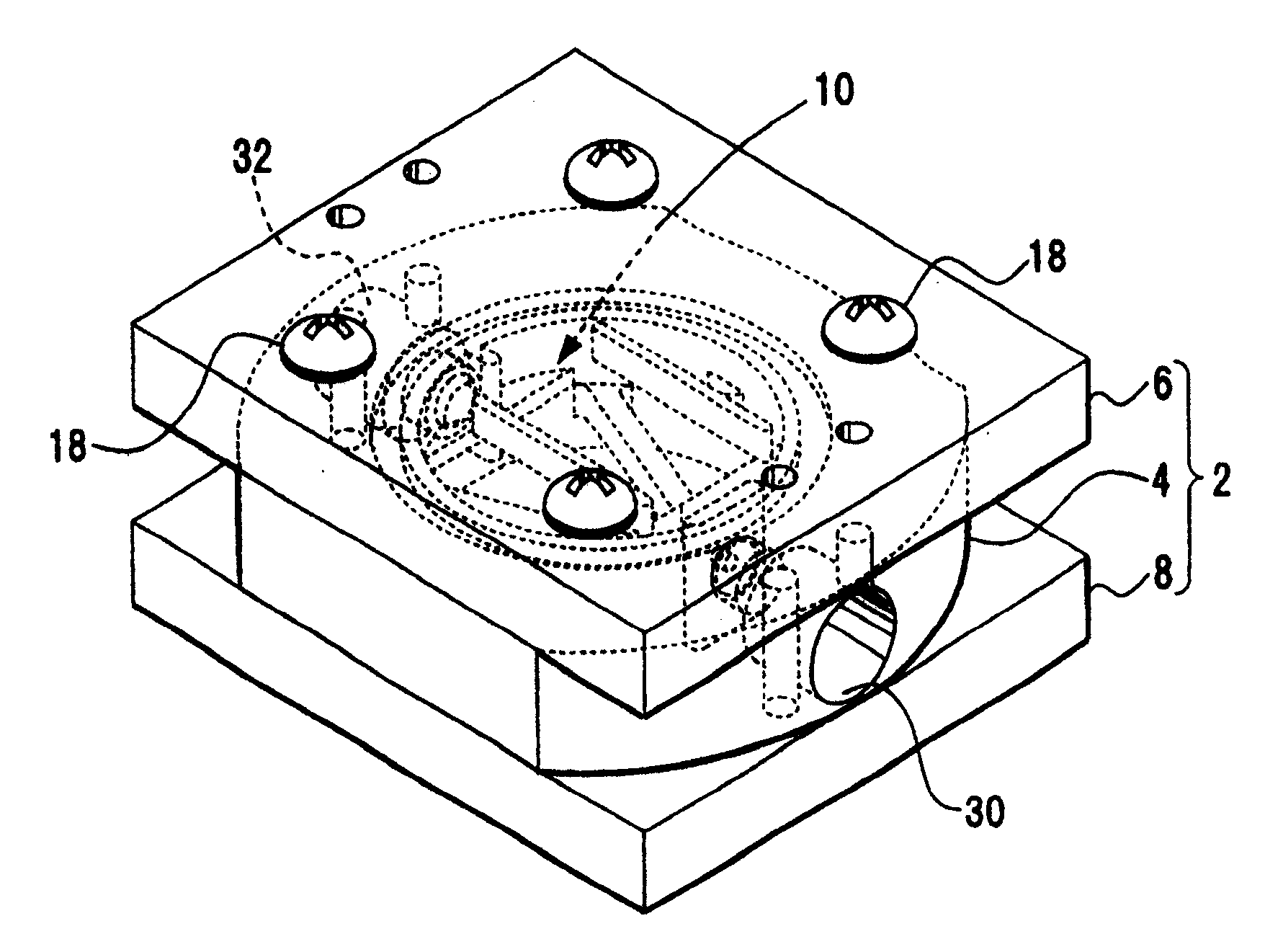
图1是示出了根据第一实施例的培养室的透视图;FIG. 1 is a perspective view showing a culture chamber according to a first embodiment;
图2是示出了培养室的分解透视图;Figure 2 is an exploded perspective view showing a culture chamber;
图3是示出了阻塞板的透视图;Figure 3 is a perspective view showing a blocking plate;
图4是示出了培养室内部的图;Fig. 4 is a diagram showing the inside of a culture chamber;
图5是图4中沿V-V线的截面视图;Fig. 5 is a sectional view along line V-V in Fig. 4;
图6是示出了主体部分的部分的透视图,其中导入口的部分被切掉;Fig. 6 is a perspective view showing part of the main body part, wherein a part of the inlet is cut away;
图7是示出了主体部分的部分的截面视图,其中导入口的部分被切掉;Fig. 7 is a sectional view showing part of the main body part, wherein a part of the inlet is cut away;
图8是示出了主体部分的部分的透视图,图中为从培养空间部分现察排出口的部分的情况;Fig. 8 is a perspective view showing part of the main body part, in which the part of the discharge port is observed from the culture space part;
图9是示出了主体部分的部分的透视图,其中排出口的部分被切掉;Fig. 9 is a perspective view showing part of the main body part, wherein part of the discharge port is cut away;
图10是示出了其中放置有培养对象的培养室的平面图;Fig. 10 is a plan view showing a culture chamber in which a culture object is placed;
图11是图10中沿XI-XI线的截面视图;Fig. 11 is a sectional view along line XI-XI in Fig. 10;
图12是示出了在导入口的部分的培养液流的图;Fig. 12 is a diagram showing a flow of culture fluid at a portion of an introduction port;
图13是示出了在培养空间部分的培养液流的图;Fig. 13 is a diagram showing the flow of culture fluid in the culture space portion;
图14是示出了在排出口的部分的培养液流的图;Fig. 14 is a diagram showing a part of the culture liquid flow at the discharge port;
图15A和图15B是示出了在培养空间部分的培养液流的图;15A and 15B are diagrams showing the flow of culture fluid in the culture space portion;
图16是示出了培养液交换状态的图;Fig. 16 is a diagram showing a culture fluid exchange state;
图17是示出了培养液交换状态的图;Fig. 17 is a diagram showing a culture fluid exchange state;
图18是示出了培养液交换状态的图;Fig. 18 is a diagram showing a culture fluid exchange state;
图19是示出了培养液交换状态的图;Fig. 19 is a diagram showing a culture fluid exchange state;
图20是示出了根据第二实施例的培养设备的图;Fig. 20 is a diagram showing a culture device according to a second embodiment;
图21是示出了根据第三实施例的培养室的图;FIG. 21 is a diagram showing a culture chamber according to a third embodiment;
图22是示出了传统的培养液交换的图;以及Figure 22 is a diagram showing conventional medium exchange; and
图23是示出了传统的培养液交换的图。Fig. 23 is a diagram showing conventional culture solution exchange.
具体实施方式 Detailed ways
[第一实施例][first embodiment]
根据本发明的第一实施例通过参考图1、图2、图3、图4和图5进行解释。图1是示出了培养室的透视图,图2是示出了培养室的分解透视图,图3是示出了一个阻塞板的透视图,图4是示出在阻塞板被移开状态下的培养室的图,以及图5是图4中沿V-V线的截面视图。A first embodiment according to the present invention is explained by referring to FIGS. 1 , 2 , 3 , 4 and 5 . 1 is a perspective view showing a culture chamber, FIG. 2 is an exploded perspective view showing a culture chamber, FIG. 3 is a perspective view showing a blocking plate, and FIG. 4 is a view showing a state in which the blocking plate is removed. Figure 5 is a cross-sectional view along line V-V in Figure 4.
培养室2具有由圆柱体构成的主体部分4,且还具有第一和第二阻塞板6和8,它们阻塞了主体部分4。通过这些阻塞板,培养室2构成圆柱形的培养空间部分10。也就是说,该培养空间部分10由第一内壁表面11和内壁表面13、15构成,第一内壁表面11包括由主体部分4构成的环形形状的曲面,内壁表面13和15则作为第二内壁表面,构成了流动安排部分。内壁表面13(图3)形成了阻塞板6的平面,内壁表面15形成了阻塞板8的平面。培养对象12(图10),例如活体的细胞和组织,以及培养液14容纳在该培养空间部分10中。主体部分4和阻塞板6和8例如由不锈钢或玻璃构成。例如,主体部分4和阻塞板6和8如下统一为一体。使得螺栓18穿过多个形成在主体部分4和阻塞板6上的通孔16,且这些螺栓18旋入到形成在阻塞板8的侧面的螺纹孔20中。因此,主体部分4和阻塞板6和8全体固定,使得主体部分4夹在阻塞板6和8之间,且培养空间部分10通过形成在主体部分4内的内壁表面11和阻塞板6和8的内壁表面13和15而形成。在主体部分4的阻塞板6和8的每个的接触表面部分形成环绕培养空间部分10的槽部分22和24(图5)。在这些槽部分22和24中,O型环26和28被定位且分别夹在主体部分4与阻塞板6和8之间部分。因此培养空间部分10被密封。The
在主体部分4中,导入口30形成为导入部分,它导入培养液14到培养空间部分10中,且排出口32形成为排出部分,它从培养空间部分10中排出培养液14。该导入口30和排出口32以培养空间部分10为中心相互相对,且还形成在与培养空间部分10的中心方向成直角的方向上。导入口30和排出口32连接有用于培养液14的循环管34,提供了密封那些连接的部分的O型环36和38。In the
在主体部分4的培养空间部分10中,作为安排培养液14的液体流动的流动安排部分,垂直壁40形成在导入口30的开口部分侧处,且还形成了小空间部分44,它被垂直壁40和培养空间部分10的内壁表面11所围绕。进一步地,在小空间部分44和阻塞板6和8的内壁表面13和15之间的部分形成了缝隙部分46和48(图5)。也就是说,小空间部分44与培养空间部分10通过缝隙部分46和48连通,且从导入口30导入的培养液14通过缝隙部分46和48被从小空间部分44引导到培养空间部分10内部。In the
在培养空间部分10,作为支撑培养对象12的支撑部分,提供了一对形成为V形的支撑条50和52,它在小空间部分44的垂直壁40和相对于垂直壁40的壁表面部分之间桥接。这些支撑条50和52提供在从培养空间部分10的深度方向的中心部分位移到阻塞板8侧的位置,且形成平行于阻塞板6和8的表面。作为相对于这些支撑条50和52的支撑部分,一对垂直壁54和56提供在阻塞板6上。间隙部分58(图5)形成在支撑条50和52与垂直壁54和56之间,且培养对象12放置在间隙部分58中。进一步地,在围绕间隙部分58的培养空间部分10的内壁表面11上,人字形突出部分60和61面对面形成,使得培养对象12不与内壁表面11紧密接触。In the
培养室2的导入口30的构造通过参考图6和图7解释。图6是示出了导入口30和其邻近的被切掉的部分的透视图,而图7是示出了导入口30的邻近部分和阻塞板的截面视图。The configuration of the
导入口30是形成在主体部分4上的通孔,其方向与培养空间部分10正交。导入口30在主体部分4的外壁表面侧具有大直径孔部分64,和在其内壁表面侧具有带有小的直径的口孔部分66。大直径孔部分64和口孔部分66之间的中间部分具有阶梯形不同的直径。与此一起,形成有其上提供有O型环36的中间孔部分68和锥形孔部分70。The
进一步地,形成了小空间部分44的垂直壁40的高度设定为略微小于培养空间部分10的高度,且形成缝隙部分46和48以引导培养液14从小空间部分44到培养空间部分10。Further, the height of the
培养室2的排出32侧的构造参考图8和图9解释。图8是示出了排出口的部分的图,图中为从培养空间部分侧观察的情况,图9是示出了排出口截面的透视图。The configuration of the
在排出32围绕部分中,形成有作为排出流安排部分的格形垂直壁72,它们在排出32的中央部分相互交叉。垂直壁72由垂直壁部分74和垂直壁部分76构成,垂直壁部分74形成在平行于支撑条50和52的方向上,垂直壁部分76与垂直壁部分74以直角相会合。垂直壁部分76的一个端面78与支撑条50和52(图5)形成在同一个面上。进一步地,在垂直壁72的与排出口32相对的部分上,形成包括曲面的凹口部分80,用于扩展排出口32的入口部分。In the
进一步地,排出口32是形成在主体部分4上的通孔,其方向与培养空间部分10正交。排出口32在主体部分4的外壁表面侧具有大直径孔部分82,和在主体部分4的内壁表面侧具有小直径的孔部分84。大直径孔部分82和小直径孔部分84的中间部分具有阶梯形不同的直径。与此一起,形成有其上提供有O型环38的中间孔部分86和锥形孔部分88。Further, the
进一步地,如图10(培养室2示出为处于阻塞板6被移开的状态下)和图11(沿图10中XI-XI线的截面视图)所示,在培养室2的培养空间部分10中,培养对象12安排在被突出部分60和62、支撑条50和52以及垂直壁54和56所围绕的空间部分,而不与内壁表面11、13和15紧密接触,且保持为维持在漂浮状态。Further, as shown in Figure 10 (the
随后,参考图12、图13和图14解释液体供给方法和培养室2内的培养液14的流动。图12是示出了从导入口和小空间部分到达培养空间部分的培养液的流动的图,图13是示出了在培养空间部分内的培养液的流动的图,图14是示出了从培养空间部分到达排出口的培养液的流动的图。Subsequently, the liquid supply method and the flow of the
如在图12中所示,从导入口30被导入培养空间部分10的培养液14的流速变得较快,其原因是开口直径从大直径孔部分64向口孔部分66变窄,且该培养液14到达小空间部分44。因存在于口孔部分66前方部分的垂直壁40,培养液14的流速减小,且被引导到缝隙部分“和48侧。因此,出现来自缝隙部分46和48沿内壁表面13和15的流动,且该流动沿培养空间部分10的内壁表面11运动。As shown in FIG. 12, the flow velocity of the
如图13中所示,在培养空间部分10中,培养液14通过柯恩达效应沿内壁表面13和15移动。沿内壁表面13和15移动的培养液14逐渐地扩散到培养空间部分10内的培养液14中,且在培养空间部分10内的培养液14中混合,同时逐渐地减小速度。As shown in FIG. 13, in the
然后培养空间部分10中的培养液14向排出口32流动。如图14所示,因为格形垂直壁72存在于排出口32附近,培养液14被从在其正交部分形成为小的排出口32排出。The
培养液14的流速小于临界雷诺数,且流速非常慢。因此,通过流入物给出的培养液14维持层流状态流动。与此一起,通过流入物给出的培养液14逐渐地扩散到已经填充的培养液14中且混合到那里现存的培养液14中。然后,与通过流入物给出的培养液14等量的培养液14从培养空间部分10排出。The flow velocity of the
随后,参考图15A、图15B、图16、图17、图18和图19中所示的实验结果解释培养室2内的培养液14的交换功能。图15A和图15B是培养空间部分中培养液的总体流动的图。图16是以时间次序示出了对应于图15A中培养液交换的事态的图。图17是示出了对应于图15A的培养空间部分的每个部分内培养液交换变化的图。图18以时间次序示出了对应于图15B中培养液交换的事态的图。图19是示出了对应于图15B的培养空间部分的每个部分内培养液交换变化的图。Subsequently, the exchange function of the
在实验中,培养室2的主体部分4的内径设定为36mm,主体部分4的深度设定为15mm,培养对象12放置在主体部分4内。在此情况下,培养空间部分10的体积大约为15ml。在培养室2内,培养对象12处于其漂浮在培养液14中的状态,培养液14填充在培养空间部分10内。培养液14的流动如前所述。试图在2.5小时内在培养空间部分10内加入15ml的培养液14,该量等于培养室2的培养空间部分10的体积,必需的流量为100ul/min。In the experiment, the inner diameter of the
当培养液14的流速缓慢(当每单位时间的流量小)时,在改变培养液14的流速的情况下,如图15A所示(培养液14的流动在图5中所示的截面中),形成了沿阻塞板6和8的内壁表面13和15侧的层流。也就是说,注入到导入口30的培养液14到达培养空间部分10的内壁表面13和15。然后,培养液14流动使得薄膜因柯恩达效应沿内壁表面漂流,但是培养液14不直接流入到中央部分。因为雷诺数远远小于临界雷诺数,在很慢的流速的流量中,层流得以维持。因此,甚至当碰撞到内壁表面时,流动也不被扰乱,且培养液14沿内壁表面流动,因为流体具有沿壁流动的特征。因为培养液14为层流,摩擦阻力大。因此,培养液14漂流使得粘住内壁表面,且其流速损失。然后,新的培养液14逐渐地扩散到已经填充的培养液14中,且培养液14从培养空间部分10的内壁表面侧朝培养对象12侧逐渐地转移到新鲜的培养液14中。When the flow rate of the
进一步地,如果培养液14的流量增加,例如在设定流量为1000ul/min的情况下,培养液14成为如图15B所示的流动。也就是说,导入到小空间部分44的培养液14通过作为通道的缝隙部分46和48流动。此时,随着流量增加,培养液14成为从缝隙部分46和48散布的流动。因此,转向垂直壁40的流动也出现,且也出现在垂直壁40和培养空间部分10的内壁表面13和15之间散开的流动。即使流速为1000ul/min,雷诺数也小,例如在20的量级。流动不被扰乱,因为流动是层流,且流体的流管在直径上很大地放大。因为流管截面面积迅速放大,因连续性原理流速进一步地降低。因此其流速损失且新导入的培养液14积聚在底部侧。Further, if the flow rate of the
解释相应于图15A和图15B中所示的流速的实验结果。在图15A的情况中,如图16和图17所示,培养液14的扩散从培养空间部分10的内壁表面侧逐渐发生,且当前培养液14转移到中央部分。图17示出了关于培养空间部分10的四个点的培养液14交换的转变,即点A(排出口32的部分)、点B(阻塞板6侧的壁表面)、点C(阻塞板8侧的壁表面)和点D(导入口30部分)。进一步地,图18和图19示出了相应于图15B的实验结果。在该情况下,培养液14从培养空间部分10的下部侧移动到新培养液14中,培养液14的新部分和旧部分形成了层来流动,且旧培养液14被排出使得它从排出口32被推出。因此在一倍半的流的量导入到培养空间部分10中时,培养液14几乎被新的培养液14所交换。Experimental results corresponding to the flow rates shown in Figures 15A and 15B are explained. In the case of FIG. 15A , as shown in FIGS. 16 and 17 , diffusion of the
该培养液14的流类似于用于控制流体的流体控制器件的流动。在流体控制器件中,流体以分叉成Y形的两个方向中的任一个的方向流动,且如果在Y形前的点给予流动一些动作,则流动在另一个方向改变。理解的是,根据培养空间部分10的内部构造,通过改变流量,发生沿特定壁表面的流动,或发生层流模式,它被改变为在通过多个壁表面形成的流管中扩散的流动。即使像这样的层流模式发生,刺激和/或应力不施加在被培养的培养对象12上,因为流速低。也就是说,通过实验确证不需要的应力,如因常规培养所导致的剪应力几乎不发生。The flow of the
进一步地,排出口32侧曾经从大直径减小到小直径,且在大直径前的部分具有格形垂直壁72。以此,流速的快速部分设计为不接近培养对象12。更甚者,因为排出口32被垂直壁72分为四个部分,如果它们中的一个被阻塞,则抽吸压不变成强的状态。因此,培养对象12等不被抽吸到排出口32侧,且不流出培养空间部分10。也就是说,没有导致循环流的事物,例如因从排出口32侧流出的培养液14导致的漩涡。另外,可以使得混合到培养空间部分10的气泡从大直径的排出口32流出。Further, the
列举了该实施例的特征,它们如下。The features of this embodiment are enumerated and they are as follows.
(1)可以控制培养室2内的培养液14的交换,且执行为在交换培养液14时不给予培养对象12任何应力。(1) The exchange of the
(2)可以倾注培养液14,根据柯恩达效应沿内壁表面导入该培养液14且使其从那里扩散。(2) The
(3)如后文中提到,培养室2适合于培养液14的循环,其中形成封闭回路以执行稳定的培养液14的交换,且使用能够供给预定量的液体的泵。(3) As mentioned later, the
(4)因为培养对象12不暴露于流速大的喷流,可以执行稳定的培养。(4) Since the
(5)小空间部分44被预先设置,且培养液14通过作为喷出口的缝隙部分46和48渐渐地倾注到培养空间部分10内。因此实现培养液14的交换。(5) The
(6)通过增加培养液14的流量,流管的直径被放大,且流速通过扩大直径减小。以此,可以缓慢地从培养空间部分10的下部部分移动为新培养液14。(6) By increasing the flow rate of the
(7)在排出口32侧,设定了大直径的通道,且因此培养液14的流速减小。在此情况下,提供了格形垂直壁72,且因此培养对象12不暴露于快速收缩流附近的流动。还可以防止培养对象12外流。(7) On the
(8)通过调节流速,可以选择例如最适宜的层流的流动。(8) By adjusting the flow rate, it is possible to select a flow such as an optimum laminar flow.
[第二实施例][Second embodiment]
随后,参考图20解释本发明的第二实施例。图20是示出了培养设备的图。在图20中,与图1和图11相同的部分以相同的参考数字指示。Subsequently, a second embodiment of the present invention is explained with reference to FIG. 20 . Fig. 20 is a diagram showing a culture device. In FIG. 20, the same parts as those in FIG. 1 and FIG. 11 are denoted by the same reference numerals.
培养设备100是通过使用前述的培养室2来培养培养对象12的构造。培养室2整合在培养回路102中。在该培养回路102中,使用前述的循环管34,还提供了培养液袋104、气体交换部分106、灌注泵108和背压调节阀110。培养回路102建立在培养器112中。在培养液袋104中,存储有包括培养必需的营养物、生长因子和抗生素的培养液14。气体交换部分106是形成在循环管34内的透气功能部分,且执行在培养器112的内部空间和培养液14之间的气体交换。The
灌注泵108是液体供给装置,它使得培养液14连续地或间歇地的循环,且还在培养器112外部具有促动器114,该促动器通过电信号产生驱动动力。进一步地,背压调节阀110是相应于培养液14的供给调节培养室2的背压的装置,且还在培养器112外部具有促动器116,该促动器通过电信号产生驱动动力。控制单元118连接到这些促动器114和116上。控制单元118由个人电脑等构成,且具有CPU(中央处理器),以及ROM(只该存储器)和RAM(随机存取存储器)作为存储装置。在ROM内存储有培养控制程序。希望的控制模式被从控制单元118通过输入到输入单元120的设置输入给到促动器114和116,且控制培养液14的循环形式。例如,通过输入单元120选择关于培养液14的流量、背压调节阀等且通过控制单元118根据其指令实行培养操作。The
在像这样的构造中,通过驱动灌注泵108使培养液14流经培养回路102。通过在气体交换部分106中执行的吸收气体,使得培养液14的气体分压几乎等同于培养器112内部的气体分压。也就是说,培养液14被调节为含有培养所需的氧气和二氧化碳气的培养液14。通过灌注泵将该培养液14供给到培养室2,作为培养对象12的细胞或组织被培养。培养对象12从培养液14中消耗营养物、氧气等,而培养对象12分泌出的的分泌物混合到培养液14。培养室2的培养液14在其压力下被背压调节阀110调节并进入培养液袋104。In a configuration like this, the
在上述的培养设备100中,通过安装前述的培养室2,由培养液袋104供给的培养液14因柯恩达效应沿培养室2的内壁表面流动,且被扩散以快速地交换。与此一起,在其交换时,没有事物给予培养对象12过度的刺激和/或应力。因此,培养设备100为形成最适宜的培养环境作出了贡献。In the above-mentioned
关于培养液14的循环,具有使得培养室2内的培养液14通过由灌注泵108驱动连续向培养室2渐渐地供给新培养液14而逐渐地交换的方法。进一步地,具有通过由灌注泵驱动以固定的时间间隔一次全部地供给(然而不是迅速的供给)培养液14而使得培养液14交换的方法。也可以使用这些方法中的任意一个,或者也可以组合使用这些方法。另外,通过将用过的培养液14经过背压调节阀排出到与培养液袋104不同袋,也可以总是将新鲜的培养液14供给到培养室2。Regarding the circulation of the
[第三实施例][Third embodiment]
随后,参考图21解释本发明的第三实施例。图21是示出了根据第三实施例的培养室的图。在图21中,与图11中那些相同的部分以相同的参考数字显示。Subsequently, a third embodiment of the present invention is explained with reference to FIG. 21 . Fig. 21 is a diagram showing a culture chamber according to a third embodiment. In FIG. 21, the same parts as those in FIG. 11 are shown with the same reference numerals.
对于该培养室2,提供有压力接收板122以取代前述的阻塞板8。培养室2是给出了从外侧经过压力接收板122到培养对象12的压力的构造。压力接收板122例如可以通过PFA(四氟乙烯全氟烃基乙烯基醚)膜形成。进一步地,为压力接收板122提供有压力单元124,且培养室2构造为使得压力单元124由前述的控制单元118控制。根据像这样的构造,可以通过来自压力单元124的压力给出希望的对培养对象12的刺激。For this
如上所述,本发明涉及使用培养液的培养室,且提高了培养液的交换功能。与此一起,没有导致对培养对象的过度的刺激和/或应力。因此本发明可以广泛地应用于培养人类或动物的细胞或组织。As described above, the present invention relates to a culture chamber using a culture solution, and improves the exchange function of the culture solution. Along with this, no undue irritation and/or stress to the cultured subjects results. Therefore, the present invention can be widely applied to culturing human or animal cells or tissues.
虽然最好的实现本发明的模式、目的、构造和操作与效应已经如上详细论述,本发明不限于此类实现发明的实施例,且当然发明可以被本领域技术人员基于权利要求书和发明具体实施方式所披露的发明的要旨和精神进行不同的变化或修改,且此类变化或修改和各种推测的结构、修改例子等包括在发明的范围内,且说明书的描述和附图不被限制性地理解。Although the mode, purpose, construction and operation and effects of the best implementation of the present invention have been discussed in detail above, the present invention is not limited to such embodiments of the implementation of the invention, and of course the invention can be developed by those skilled in the art based on the claims and invention specific Various changes or modifications are made to the gist and spirit of the invention disclosed in the embodiments, and such changes or modifications and various presumed structures, modified examples, etc. are included in the scope of the invention, and the description of the specification and the drawings are not limited understanding.
Claims (13)
Applications Claiming Priority (3)
| Application Number | Priority Date | Filing Date | Title |
|---|---|---|---|
| JP2005-208752 | 2005-07-19 | ||
| JP2005208752A JP4689383B2 (en) | 2005-07-19 | 2005-07-19 | Culturing chamber, culturing apparatus, and method for feeding culture solution |
| JP2005208752 | 2005-07-19 |
Publications (2)
| Publication Number | Publication Date |
|---|---|
| CN1900265A CN1900265A (en) | 2007-01-24 |
| CN100434503C true CN100434503C (en) | 2008-11-19 |
Family
ID=37102544
Family Applications (1)
| Application Number | Title | Priority Date | Filing Date |
|---|---|---|---|
| CNB2006100041153A Expired - Fee Related CN100434503C (en) | 2005-07-19 | 2006-02-20 | Culture chamber, culture device and liquid supply method for cell or tissue culture |
Country Status (5)
| Country | Link |
|---|---|
| US (1) | US7892821B2 (en) |
| EP (1) | EP1746154B1 (en) |
| JP (1) | JP4689383B2 (en) |
| KR (1) | KR100841189B1 (en) |
| CN (1) | CN100434503C (en) |
Families Citing this family (16)
| Publication number | Priority date | Publication date | Assignee | Title |
|---|---|---|---|---|
| CA2613945A1 (en) * | 2007-12-12 | 2009-06-12 | The Hospital For Sick Children | Bladder bioreactor |
| JP2012147678A (en) * | 2009-05-14 | 2012-08-09 | Otake:Kk | Multiple culture apparatus for single sample |
| JP4602460B1 (en) * | 2009-07-02 | 2010-12-22 | 株式会社日立製作所 | Cell culture vessel |
| US20130189671A1 (en) * | 2010-08-19 | 2013-07-25 | Jan H. Hoh | Cell Culture System and Method of Use Thereof |
| KR101403536B1 (en) | 2011-12-23 | 2014-06-03 | 주식회사 넥스비보 | Cell cultivation device, cell cultivation system and method of cultivating using the same |
| US9303244B1 (en) * | 2012-08-18 | 2016-04-05 | Mehran Kasra | Hydrostatic pressure generator device |
| JP6492449B2 (en) * | 2013-12-26 | 2019-04-03 | 株式会社Ihi | Cell culture equipment |
| US20170369830A1 (en) * | 2014-12-11 | 2017-12-28 | Icomes Lab Co., Ltd. | Cell culture method and cell culture device |
| JP2017023131A (en) * | 2015-07-23 | 2017-02-02 | オリンパス株式会社 | Cell culture apparatus |
| TWI732800B (en) * | 2015-11-25 | 2021-07-11 | 美商拜耳保健公司 | Syringe fill adapter and fluid transfer assembly |
| WO2017091043A1 (en) * | 2015-11-26 | 2017-06-01 | 부산대학교 산학협력단 | Microfluidic perfusion cell culture system |
| KR101878569B1 (en) | 2015-11-26 | 2018-07-16 | 부산대학교 산학협력단 | Perfusion cell culture system using micro fluidic system |
| EP3504315A4 (en) | 2016-08-27 | 2020-04-15 | 3D Biotek, LLC | Bioreactor |
| CN108179109A (en) * | 2018-03-12 | 2018-06-19 | 青岛农业大学 | A kind of microorganism intelligence liquid-based culture dish |
| US11566217B2 (en) * | 2019-08-13 | 2023-01-31 | Flaskworks, Llc | Duty cycle for cell culture systems |
| KR102669796B1 (en) * | 2023-11-06 | 2024-05-27 | 주식회사 한국마이크로그린 | An apparatus for cultivating peanut sprouts |
Citations (3)
| Publication number | Priority date | Publication date | Assignee | Title |
|---|---|---|---|---|
| JPS63233779A (en) * | 1987-03-24 | 1988-09-29 | Sumitomo Electric Ind Ltd | Cell culture device |
| WO1990015859A1 (en) * | 1989-06-14 | 1990-12-27 | Board Of Regents, The University Of Texas System | Dynamic flow cell culture system |
| EP1382670A1 (en) * | 2001-04-24 | 2004-01-21 | Takagi Industrial Co., Ltd. | Cell and structure incubator |
Family Cites Families (16)
| Publication number | Priority date | Publication date | Assignee | Title |
|---|---|---|---|---|
| US4908319A (en) * | 1988-03-16 | 1990-03-13 | Smyczek Peter J | Laboratory apparatus |
| JP2585866B2 (en) * | 1990-09-19 | 1997-02-26 | ベリー,エリック・スコット | Continuous high density cell culture system |
| US5744366A (en) * | 1992-05-01 | 1998-04-28 | Trustees Of The University Of Pennsylvania | Mesoscale devices and methods for analysis of motile cells |
| US5843766A (en) * | 1995-06-07 | 1998-12-01 | Advanced Tissue Sciences, Inc. | Apparatus for the growth and packaging of three dimensional tissue cultures |
| JPH0915859A (en) * | 1995-06-30 | 1997-01-17 | Hitachi Chem Co Ltd | Colored image forming photoensitive solution, manufacture of color filter using it, and color filter |
| JP3072368B2 (en) * | 1998-02-18 | 2000-07-31 | 筑波大学長 | High-density culture method of hepatocytes and apparatus therefor |
| US5989913A (en) * | 1998-07-02 | 1999-11-23 | Charles Daniel Anderson | Culture vessel for growing or culturing cells, cellular aggregates, tissues and organoids and methods for using the same |
| JP3572341B2 (en) | 2000-11-21 | 2004-09-29 | 独立行政法人 宇宙航空研究開発機構 | Medium exchange system for cell culture vessels |
| JP2003061642A (en) * | 2001-08-30 | 2003-03-04 | Takagi Ind Co Ltd | Cell / tissue culture equipment |
| JP2004016194A (en) | 2002-06-20 | 2004-01-22 | Hitachi Medical Corp | Cell culture apparatus |
| JP4230176B2 (en) * | 2002-06-28 | 2009-02-25 | 独立行政法人科学技術振興機構 | Embryo culture apparatus and method for controlling embryo asymmetry |
| JP2004113175A (en) * | 2002-09-27 | 2004-04-15 | Olympus Corp | Apparatus for cell culture and detection |
| JP4389035B2 (en) | 2002-10-30 | 2009-12-24 | 財団法人生産技術研究奨励会 | Cell culture device, bioreactor and cell culture chamber |
| JP4445765B2 (en) | 2004-02-05 | 2010-04-07 | グンゼ株式会社 | Cell culture equipment |
| CA2581296A1 (en) * | 2004-09-29 | 2006-06-08 | J. Wayne Van Toever | Bio-filter with low density media and toroidal media stirring configuration |
| JP2007008823A (en) * | 2005-06-28 | 2007-01-18 | Hiromi Sato | Therapeutic agent for athlete's foot |
-
2005
- 2005-07-19 JP JP2005208752A patent/JP4689383B2/en not_active Expired - Lifetime
-
2006
- 2006-01-30 EP EP06250497.2A patent/EP1746154B1/en not_active Expired - Lifetime
- 2006-02-09 KR KR1020060012511A patent/KR100841189B1/en not_active Expired - Fee Related
- 2006-02-17 US US11/307,692 patent/US7892821B2/en active Active
- 2006-02-20 CN CNB2006100041153A patent/CN100434503C/en not_active Expired - Fee Related
Patent Citations (3)
| Publication number | Priority date | Publication date | Assignee | Title |
|---|---|---|---|---|
| JPS63233779A (en) * | 1987-03-24 | 1988-09-29 | Sumitomo Electric Ind Ltd | Cell culture device |
| WO1990015859A1 (en) * | 1989-06-14 | 1990-12-27 | Board Of Regents, The University Of Texas System | Dynamic flow cell culture system |
| EP1382670A1 (en) * | 2001-04-24 | 2004-01-21 | Takagi Industrial Co., Ltd. | Cell and structure incubator |
Also Published As
| Publication number | Publication date |
|---|---|
| KR100841189B1 (en) | 2008-06-24 |
| EP1746154A1 (en) | 2007-01-24 |
| JP4689383B2 (en) | 2011-05-25 |
| US20070020750A1 (en) | 2007-01-25 |
| KR20070011068A (en) | 2007-01-24 |
| JP2007020493A (en) | 2007-02-01 |
| EP1746154B1 (en) | 2019-05-22 |
| US7892821B2 (en) | 2011-02-22 |
| CN1900265A (en) | 2007-01-24 |
Similar Documents
| Publication | Publication Date | Title |
|---|---|---|
| CN1900265A (en) | Culture chamber, culture apparatus and liquid supplying method for cell or tissue cultivation | |
| CN103476920B (en) | Apparatuses for and methods of processing cells and related structures | |
| US7855070B2 (en) | Centimeter-scale, integrated diagnostics incubator for biological culturing | |
| ES2327231T3 (en) | INTEGRATED MICROFLUIDIC CONTROL THAT USES PROGRAMMABLE TACTILE ACTUATORS. | |
| US9023642B2 (en) | Method and apparatus for a miniature bioreactor system for long-term cell culture | |
| US20100151571A1 (en) | Centimeter-scale, integrated diagnostics incubator for biological culturing | |
| JPS63151306A (en) | Device and method for mass transfer including biological and/or pharmacological medium | |
| JP6293900B2 (en) | CULTURE DEVICE, CULTURE METHOD USING SAME, AND SCREEN AGGREGATE SELECTION METHOD | |
| CN107354094B (en) | The equally distributed micro-current controlled cell culture chip of cell and cell sample injection method | |
| ES2983869T3 (en) | Procedure for enriching gas and simultaneously displacing a fluid, and system for controlling the cellular environment on a corresponding multi-well cell culture plate | |
| CN112608841A (en) | Microfluidic system for tumor organoid culture and drug experiments and use method thereof | |
| WO2019233245A1 (en) | Microdroplet treatment device and use method thereof | |
| CN1909847A (en) | Apparatus for handling cells, embryos or oocytes | |
| CN113388516B (en) | Culture device | |
| US9683207B2 (en) | Method for growing cells in hollow fibers | |
| CN118308187A (en) | Skin chip and skin model construction method | |
| KR102411446B1 (en) | Cell culture device | |
| CN220143421U (en) | Microfluidic chip with Tesla valve structure | |
| CN118834753A (en) | Three-dimensional electro-stimulation cell culture platform based on microfluidic technology | |
| CN114762498B (en) | A biological material processing device | |
| KR100992387B1 (en) | Cell incubator and cell culture method using stimulus | |
| CN219490028U (en) | Portable observable automatic liquid-changing cell culture device | |
| CN223697795U (en) | A microfluidic chip | |
| CN117229879A (en) | Bioreactor and reaction chamber | |
| CN217230773U (en) | Micro-fluidic chip for generating stable concentration gradient |
Legal Events
| Date | Code | Title | Description |
|---|---|---|---|
| C06 | Publication | ||
| PB01 | Publication | ||
| C10 | Entry into substantive examination | ||
| SE01 | Entry into force of request for substantive examination | ||
| C14 | Grant of patent or utility model | ||
| GR01 | Patent grant | ||
| C56 | Change in the name or address of the patentee |
Owner name: PURPOSE, LTD. Free format text: FORMER NAME: TAKAGI INDUSTRIAL CO. LTD. |
|
| CP01 | Change in the name or title of a patent holder |
Address after: Shizuoka Patentee after: PURPOSE Co.,Ltd. Address before: Shizuoka Patentee before: Takagi Industrial Co.,Ltd. |
|
| CF01 | Termination of patent right due to non-payment of annual fee |
Granted publication date: 20081119 |
|
| CF01 | Termination of patent right due to non-payment of annual fee |