CN100422690C - Angle detection signal processing system - Google Patents
Angle detection signal processing system Download PDFInfo
- Publication number
- CN100422690C CN100422690C CNB2005100921731A CN200510092173A CN100422690C CN 100422690 C CN100422690 C CN 100422690C CN B2005100921731 A CNB2005100921731 A CN B2005100921731A CN 200510092173 A CN200510092173 A CN 200510092173A CN 100422690 C CN100422690 C CN 100422690C
- Authority
- CN
- China
- Prior art keywords
- signal
- angle
- phase
- unit
- data
- Prior art date
- Legal status (The legal status is an assumption and is not a legal conclusion. Google has not performed a legal analysis and makes no representation as to the accuracy of the status listed.)
- Expired - Fee Related
Links
- 238000001514 detection method Methods 0.000 title claims abstract description 213
- 238000012545 processing Methods 0.000 title claims description 190
- 238000005086 pumping Methods 0.000 claims description 61
- 230000007274 generation of a signal involved in cell-cell signaling Effects 0.000 claims description 48
- 238000004364 calculation method Methods 0.000 claims description 16
- 230000005284 excitation Effects 0.000 abstract description 23
- 238000010586 diagram Methods 0.000 description 58
- 239000013256 coordination polymer Substances 0.000 description 48
- 230000006870 function Effects 0.000 description 44
- 239000013598 vector Substances 0.000 description 36
- 101100350613 Arabidopsis thaliana PLL1 gene Proteins 0.000 description 24
- 101100082028 Arabidopsis thaliana PLL2 gene Proteins 0.000 description 24
- 238000007792 addition Methods 0.000 description 18
- 238000000034 method Methods 0.000 description 16
- 238000010276 construction Methods 0.000 description 6
- 230000002441 reversible effect Effects 0.000 description 6
- 230000002950 deficient Effects 0.000 description 5
- 238000005070 sampling Methods 0.000 description 5
- 230000004304 visual acuity Effects 0.000 description 5
- 230000008901 benefit Effects 0.000 description 4
- 230000008859 change Effects 0.000 description 4
- 238000006243 chemical reaction Methods 0.000 description 4
- 239000000284 extract Substances 0.000 description 4
- 238000001228 spectrum Methods 0.000 description 4
- 230000005355 Hall effect Effects 0.000 description 3
- ATJFFYVFTNAWJD-UHFFFAOYSA-N Tin Chemical compound [Sn] ATJFFYVFTNAWJD-UHFFFAOYSA-N 0.000 description 3
- 230000002411 adverse Effects 0.000 description 3
- 239000003990 capacitor Substances 0.000 description 3
- 230000000694 effects Effects 0.000 description 3
- 230000003287 optical effect Effects 0.000 description 3
- 101000685663 Homo sapiens Sodium/nucleoside cotransporter 1 Proteins 0.000 description 2
- 102100023116 Sodium/nucleoside cotransporter 1 Human genes 0.000 description 2
- 230000015572 biosynthetic process Effects 0.000 description 2
- 238000005520 cutting process Methods 0.000 description 2
- 238000013461 design Methods 0.000 description 2
- 230000006866 deterioration Effects 0.000 description 2
- 238000005265 energy consumption Methods 0.000 description 2
- 238000005516 engineering process Methods 0.000 description 2
- 238000012423 maintenance Methods 0.000 description 2
- 238000004519 manufacturing process Methods 0.000 description 2
- 230000009467 reduction Effects 0.000 description 2
- 230000000630 rising effect Effects 0.000 description 2
- 230000003068 static effect Effects 0.000 description 2
- 230000007704 transition Effects 0.000 description 2
- 230000003321 amplification Effects 0.000 description 1
- 230000002238 attenuated effect Effects 0.000 description 1
- 230000005540 biological transmission Effects 0.000 description 1
- 230000002051 biphasic effect Effects 0.000 description 1
- 230000001413 cellular effect Effects 0.000 description 1
- 238000004891 communication Methods 0.000 description 1
- 238000013329 compounding Methods 0.000 description 1
- 238000004590 computer program Methods 0.000 description 1
- 238000012937 correction Methods 0.000 description 1
- 238000000354 decomposition reaction Methods 0.000 description 1
- 239000000428 dust Substances 0.000 description 1
- 230000005674 electromagnetic induction Effects 0.000 description 1
- 230000007613 environmental effect Effects 0.000 description 1
- 230000004907 flux Effects 0.000 description 1
- 230000008676 import Effects 0.000 description 1
- 238000007689 inspection Methods 0.000 description 1
- 230000000670 limiting effect Effects 0.000 description 1
- 238000005259 measurement Methods 0.000 description 1
- 230000007246 mechanism Effects 0.000 description 1
- 230000003278 mimic effect Effects 0.000 description 1
- 230000004048 modification Effects 0.000 description 1
- 238000012986 modification Methods 0.000 description 1
- 238000003199 nucleic acid amplification method Methods 0.000 description 1
- 230000010355 oscillation Effects 0.000 description 1
- 238000005096 rolling process Methods 0.000 description 1
- 230000000087 stabilizing effect Effects 0.000 description 1
- 230000004936 stimulating effect Effects 0.000 description 1
- 238000003860 storage Methods 0.000 description 1
- 230000001360 synchronised effect Effects 0.000 description 1
- 230000009897 systematic effect Effects 0.000 description 1
Images


Classifications
-
- G—PHYSICS
- G01—MEASURING; TESTING
- G01D—MEASURING NOT SPECIALLY ADAPTED FOR A SPECIFIC VARIABLE; ARRANGEMENTS FOR MEASURING TWO OR MORE VARIABLES NOT COVERED IN A SINGLE OTHER SUBCLASS; TARIFF METERING APPARATUS; MEASURING OR TESTING NOT OTHERWISE PROVIDED FOR
- G01D5/00—Mechanical means for transferring the output of a sensing member; Means for converting the output of a sensing member to another variable where the form or nature of the sensing member does not constrain the means for converting; Transducers not specially adapted for a specific variable
- G01D5/12—Mechanical means for transferring the output of a sensing member; Means for converting the output of a sensing member to another variable where the form or nature of the sensing member does not constrain the means for converting; Transducers not specially adapted for a specific variable using electric or magnetic means
- G01D5/244—Mechanical means for transferring the output of a sensing member; Means for converting the output of a sensing member to another variable where the form or nature of the sensing member does not constrain the means for converting; Transducers not specially adapted for a specific variable using electric or magnetic means influencing characteristics of pulses or pulse trains; generating pulses or pulse trains
- G01D5/245—Mechanical means for transferring the output of a sensing member; Means for converting the output of a sensing member to another variable where the form or nature of the sensing member does not constrain the means for converting; Transducers not specially adapted for a specific variable using electric or magnetic means influencing characteristics of pulses or pulse trains; generating pulses or pulse trains using a variable number of pulses in a train
-
- G—PHYSICS
- G01—MEASURING; TESTING
- G01D—MEASURING NOT SPECIALLY ADAPTED FOR A SPECIFIC VARIABLE; ARRANGEMENTS FOR MEASURING TWO OR MORE VARIABLES NOT COVERED IN A SINGLE OTHER SUBCLASS; TARIFF METERING APPARATUS; MEASURING OR TESTING NOT OTHERWISE PROVIDED FOR
- G01D5/00—Mechanical means for transferring the output of a sensing member; Means for converting the output of a sensing member to another variable where the form or nature of the sensing member does not constrain the means for converting; Transducers not specially adapted for a specific variable
- G01D5/12—Mechanical means for transferring the output of a sensing member; Means for converting the output of a sensing member to another variable where the form or nature of the sensing member does not constrain the means for converting; Transducers not specially adapted for a specific variable using electric or magnetic means
- G01D5/244—Mechanical means for transferring the output of a sensing member; Means for converting the output of a sensing member to another variable where the form or nature of the sensing member does not constrain the means for converting; Transducers not specially adapted for a specific variable using electric or magnetic means influencing characteristics of pulses or pulse trains; generating pulses or pulse trains
-
- H—ELECTRICITY
- H03—ELECTRONIC CIRCUITRY
- H03M—CODING; DECODING; CODE CONVERSION IN GENERAL
- H03M1/00—Analogue/digital conversion; Digital/analogue conversion
- H03M1/12—Analogue/digital converters
- H03M1/48—Servo-type converters
- H03M1/485—Servo-type converters for position encoding, e.g. using resolvers or synchros
Abstract
A resolver use angle detection IC subjected to a phase lock operation so as to follow not an angle (t) for detection, but a phase angle omega 0 t+- thet having an offset of a frequency omega0t in the phase lock units. For this reason, when the excitation frequency omega0t is set sufficiently high with respect to the frequency of the angle thet(t), the phase angle omega 0 t+- thet to be followed in the phase lock units will not become zero. For this reason, an angle having a high precision can be found in real time regardless of the configuration not including the conventional apparatus in which the configuration is complex and the power consumption is large like a bipolar VCO and an up/down type counter.
Description
Technical field
The present invention relates to a kind of angle detection signal processing system, it is used to handle the angle detection signal of resolver to obtain angle-data.
Background technology
The cross reference of related application
The application comprises the relevant theme of submitting to Jap.P. office with on August 23rd, 2004 of Japanese patent application No.2004-242664, and its full content is hereby incorporated by.
In multiple mechanical devices, the positional information of determining turning axle and moving-member is a basic function.For example, in motor, in order to apply best torque to rotor, must be according to extremely best of the position control rotating magnetic field of rotor.For example, for automobile, in the motor of hybrid automobile (hybrid car) and power steering gear, need high reliability, angular transducer cheaply.In addition, this angular transducer has multiple application, to such an extent as to for example dozer and other construction machinery, various lathe, production equipment aerospace system.
Designed the method that is used to detect and control angle of huge amount.For example, use stepper motor for the simplest angle control.This stepper motor uses the number of the pulse that is accompanied by the rotation generation as angle information.Yet, utilize the method for stepper motor can not during rotation produce when sliding, so not talkative have a high reliability by stepping electrode detection slippage itself.
For the angle control of high reliability, generally use certain angle detector.As typical angular transducer, it all is known for example utilizing hall effect sensor to come the sensor of the relative position of detection of magnetized pattern magnetically and hall effect sensor and the other sensor by optical means (for example optical encoder) detection angles.Yet, be not sufficient to the to satisfy the demand application of high reliability of these sensors.The use of hall effect sensor is not talkative to be stable to heat and vibration, and optical means is easy to be subjected to wet goods to pollute, and also needs light source in addition, so it has the shortcoming of reliability.
At present, the stable angular transducer as having highest stabilizing is known that the angular transducer that utilizes electromagnetic induction.This angular transducer is known as " resolver ", and has the structure of similar motor substantially, as shown in figure 29.
The coil 52 that is wrapped on the rotor 51 is had frequencies omega
0Pumping signal V
EExcitation.Two coils 54 and 55 meet at right angles and are arranged in the stator 53.When rotor 51 during, in coil 54 and 55, induce following signal V around the accurate rotational angle θ of axle (t)
IAnd V
Q, as following etc.
In the formula:
V
I=V
o·Cosω
ot·Cosθ
(t) …(1)
V
Q=V
o·Cosω
ot·Sinθ
(t) …(2)
Angle detection signal processing system is by this input angle θ (t).Particularly, the signal processing apparatus with the digital data form output angle is called as " resolver-numeral (R-D) converter ".Therefore the coil that resolver only has a rotor, a stator basically and made by magnet has the feature of stability and the environmental impact of opposing such as dust or temperature.For this reason, to such an extent as to resolver is to be suitable for automobile, dozer and other construction machinery, various lathe, production equipment aerospace system most and other needs the application point of view detection system of high reliability.
For present resolver, multiple structure has been proposed.Figure 29 illustrates a kind of basic structure.About this, need rotary brush to provide exciting current to rotor.In order to remove this, structure or a kind of new structure of motor-converter have been proposed to utilize, be that its rotor does not have coil, this rotor is by the coil stimulating of stator, and the change of flux that is produced by the space change between rotor and stator by the stator sensing.Output will be called as " single-phase excitation two-phase output type " in the following description by the resolver of the signal of equation (1) and equation (2) expression.
As explained above, in multiple structure, when paying close attention to when resolver obtains signal as output, shown in equation (1) and (2), the single-phase excitation two-phase of the most common use output type resolver, this resolver have an anglec of rotation θ (t) and export the signal that is obtained by cosine function Cos θ (t) and sine function Sin θ (t) modulated excitation signal.
On the other hand, when when the simple and easy aspect of signal Processing is considered, resolver is the product Cos ω of output cosine function preferably
0The product Sin ω of t * Cos θ (t) and sine function
0The resolver of t * Sin θ (t).Yet the resolver of output sort signal must have two independently rotors 56 and 57 and two stators 58 on same axle and 59, as shown in figure 30.This method is called as " two-phase excitation two-phase output type ".It is very easy that signal Processing becomes.Yet it structurally has bigger defective, for example, two independently rotor and stator to becoming essential, mechanical mechanism complexity, and structure becomes very thick and heavy, therefore, only is to use this structure limitedly.
Simple reason below becomes the signal Processing of brief description two-phase excitation two-phase output type.Signal V from the output of two-phase excitation two-phase output type resolver
IAnd V
QCan be by following equation
V
I=Cosω
ot·Cosθ
(t)=1/2{Cos(ω
ot+θ
(t))
+Cos(ω
ot-θ
(t))} …(3)
V
Q=Sinω
ot·Sinθ
(t)=1/2{-Cos(ω
ot+θ
(t))
+Cos(ω
ot-θ
(t))} …(4)
Expression:
According to top equation, by obtain difference as follows with and, can easily obtain cosine signal Cos (ω
0T+ θ (t)) and Cos (ω
0T-θ (t)):
V
P=V
I-V
Q=Cos(ω
ot+θ(t)) …(5)
V
N=V
I+V
Q=Cos(ω
ot-θ(t)) …(6)
When switching signal by this way, for example, can obtain angle θ (t) easily by poor in the zero cross point Measuring Time of two signals.Figure 31 is the block diagram of expression signal Processing.At first, by signal V
IAnd V
QAddition and subtraction picked up signal V
PAnd V
NNext, obtain V through comparer
PAnd V
NZero crossing.Then, if for example calculate its rising edge by difference channel, and by rolling counters forward signal V
PAnd V
NEach rising edge between the number of time clock, this become and the angle θ (t) that obtains proportional.Therefore, according to the counting of this counter, can extract output by the digital conversion acquisition of angle θ (t).
Next, the explanation that is widely used in the R-D converter in the single-phase excitation two-phase output type resolver will be provided.Figure 32 illustrates its example of structure.For example, in order to obtain 12 angle-data, prepare ROM (read-only memory) (ROM), it is used for storage and has at least 11 bit resolutions, it is desirable to the sinusoidal signal and the cosine signal of 12 bit resolutions, and sinusoidal signal Sin φ (t) and cosine signal Cos φ (t) produce about any angle φ (t).They are converted into simulating signal in D/A converter.In order to make angle φ (t), from the signal V of resolver output corresponding to the angle θ (t) that will obtain
IMultiply each other with sinusoidal signal Sin φ (t), meanwhile, signal V
QMultiply each other with cosine signal Cos φ (t).Then, the former has been produced the signal V1 shown in the equation below thus by anti-phase and add the latter to:

In addition, for synchronous waves detects, with cosine signal Cos ω
0T multiply by the signal V1 of equation (7).At this moment, extracted sinusoidal signal Sin{ θ (t)-φ (t)) component.


Cosine term Cos2 ω in the equation 8
0T has high frequency, and it is attenuated in loop filter, and only extracts the low frequency term of equation end.The output of this loop filter is imported in the bipolar voltage controlled oscillator (VCO).The bipolar VCO of as shown in figure 33 this produces the polar signal that has with the pulse signal of the proportional frequency of absolute value of input signal and be used to judge the polarity of input.The incremented/decremented counter is that timing is carried out and increased progressively counting according to the polar signal of bipolar VCO at polar signal, and when polar signal execution countdown when negative.As a result, the counting of incremented/decremented counter becomes the numerical data of angle φ (t) itself.
The numerical data of the angle φ (t) that obtains is converted to the numerical data of sinusoidal signal Sin φ (t) and cosine signal Cos φ (t) by sin/cos ROM, and they are converted into simulating signal in D/A converter.Loop filter has integral characteristic and has infinitely-great DC gain, so for limited output, the normal value of input is necessary for zero.Therefore, angle φ (t) changes, so that follow angle θ (t).
As a reference, referring to the uncensored patent disclosure of Japan (Kokai) No.11-83544.
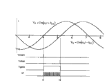
In two-phase excitation two-phase output type resolver, utilize the angle detecting method of the zero cross point of signal as shown in figure 31 to have following defective.
Figure 34 is the curve map that is illustrated in the example of part signal waveform in the circuit shown in Figure 31.In the example of Figure 34, the counting of time clock CP originates in signal V
PThe time t1 of zero crossing when occurring.Counting ends at signal V
NThe time t2 of zero crossing when occurring.This counting has reflected angle θ (t), and in fact can be used as the digital value at this angle.Extract a counting at time t2 place.
In circuit shown in Figure 31, as angle θ (t) when changing fast, the digital value that can not accurately be limited to the angle that time t2 place obtains is detected as the time point of data.This is because signal V
PZero cross point show signal V
PAt the state of time t1, and signal V
NZero cross point show signal V
NAt the state of time t2, so the angle θ (t) of phase differential can only be restricted near time t1 and t2 angle at the most between the two.In addition, mean in the output of time t2 place angular data delay has taken place significantly, up to detecting this angle and having obtained data.In addition, only can obtain a secondary data for each cycle of excitation frequency, so can not catch the continuous variation of angle.Because this defective, the R-D converter that obtains angle by zero cross point for example needing to be not suitable for obtaining in real time the application of the angle of high-speed rotating shaft.
Utilize another defective of method of the zero cross point of signal to be that this method does not have high tolerance for external noise.This is because even small noise enters near the zero cross point, the time of zero crossing also can fluctuate.
On the other hand, R-D converter shown in Figure 32 is characterised in that real-time acquisition output.The incremented/decremented counter is held the data of angle φ (t) continuously.Because angle φ (t) follows angle θ (t), postpone so exist, still general this delay is moved enough weak points with respect to the machinery of angle θ (t).In addition, the whole waveform of this systematic comparison even therefore part has stack external noise thereon, also is insensitive in zero cross detection for it.
Yet the defective that is shown in the R-D converter among Figure 32 is that it is big to handle complexity and circuit size, so power consumption is big, cost is high.Promptly need complicated bipolar VCO or incremented/decremented counter.In addition,, need have at least 11, it is desirable to the high capacity sine/cosine ROM of 12 resolution and precision, and have high-resolution D/A converter in order to obtain 12 bit resolutions.
Figure 35 is the curve map that is used to explain the necessary resolution of sin/cos ROM and D/A converter.In order to decompose angle 2 π with 12, consider sinusoidal wave maximum inclination, must be the decomposition of 12 1/ π.Promptly work as 2 π and be broken down into 2
12The time, the maximal value of the step-length of output is " 1/ (2
12/ π) ".Therefore, 10 some is not enough slightly, and 11 is necessary.When considering other error component, if expectation provides some extra tolerance limits, 12 is desirable.If only the table by a ROM provides, then need quite large-sized storer.Also has a kind of technology by reduction amount of memory such as use interpolation methods.Under any circumstance, mimic channel and data circuit that this all needs oversize consume a large amount of electric energy, and therefore cost an arm and a leg.
Therefore bipolar VCO must be difficult to be embodied as circuit from the zero frequency starting oscillation.In addition, be easy to the dead band takes place near zero frequency, become unstable so shortcoming is phaselocked loop control.
Analog multiplier circuit is the element of restriction system performance.As analog multiplier circuit, figure 36 illustrates the circuit that is called as " gilbert's type multiplier circuit " that is used for general objects.Sort circuit is a kind of analog function circuit that is widely used in the frequency mixer of radio communication circuit (frequency mixing circuit) for example.Sort circuit is excelled at leveraging the feature of bipolar transistor, so that can utilize foolproof circuit to carry out high-frequency work.Yet, for such as needs for example 12 or the high-precision signal more the R-D converter of multidigit handle, the absolute precision of this functional circuit does not reach required level.The dynamic range of the input of sort circuit for example is about 20mVp-p.Input transition deviation voltage with respect to this dynamic range is generally about 1 to 2mV.Therefore, for absolute accuracy, the scope of assurance lucky about 10%.Also have a kind of method by emission feedback resistance or other device amplification dynamic range, but offset voltage increases also, therefore, relative accuracy can not be enhanced so much.For the circuit solution,, also be difficult to guarantee 1% absolute precision even use fine setting or use method for distinguishing simultaneously.Therefore, can obtain about 8 degree of accuracy, but this is far from 12.Because this reason in high precision R-D converter, must be used replacement gilbert type multiplier circuits such as multiplication type d/a converter, thereby avoids the restriction on the precision of multiplier circuit.Therefore, in order to obtain high precision, be used to realize that the device of analog multiplier circuit becomes the factor that comprises that power consumption increases and cost increases.
Summary of the invention
It is desirable to provide a kind of angle detection signal processing system, it is simple in structure, also can obtain the high precision angle in real time.
According to the first embodiment of the present invention, a kind of angle detection signal processing system is provided, it is used for obtaining first angle information based on the detection output of resolver, this detection output comprises first angle detection signal and second angle detection signal, this first angle detection signal comprises the amplitude of first pumping signal, and this first pumping signal has the first frequency modulated by the signal of the cosine function that the has first angle (frequencies omega among first embodiment for example
0), this second angle detection signal is made of the amplitude of second pumping signal, and this second pumping signal has the first frequency of being modulated by the signal of the sine function that has first angle, and described device comprises signal processing unit, first phase locking unit, second phase locking unit and differ computing unit.
Signal processing unit is exported first signal and secondary signal, and this first signal and secondary signal have first frequency, and has simultaneously according to differing based on this first angle of this first angle detection signal and this second angle detection signal.First phase locking unit produces and to make first lockin signal of phase locking to this first signal, and first data of the phase angle of this first lockin signal of output expression.Second phase locking unit produces and to make second lockin signal of phase locking on this secondary signal, and second data of the phase angle of this second lockin signal of output expression.Differ computing unit based on the phase differential between these first data and this first lockin signal of this second data computation and this second lockin signal.
To explain the mode of operation of first aspect present invention below.In signal processing unit, produce first signal and secondary signal, they all have first frequency, and have the phase differential of basis based on first angle of first angle detection signal and second angle detection signal simultaneously.In first phase locking unit, produce first lockin signal by phase locking is obtained to first signal, and first data of the phase angle of this first lockin signal of output expression.In second phase locking unit, produce second lockin signal by phase locking is obtained on this secondary signal, and second data of the phase angle of this second lockin signal of output expression.In addition in differing computing unit, based on the phase differential between these first data and this first lockin signal of this second data computation and this second lockin signal.
Because this, the phase differential between first signal and the secondary signal has the value according to first angle.In addition, has value at first phase-locked on these signals lockin signal and the phase differential between second lockin signal according to the phase differential between first signal and the secondary signal.Therefore, the phase differential between first lockin signal and second lockin signal has according to first angle value.That is, the phase differential that differs the result of calculation of computing unit has the value according to first angle.
In first and second phase locking units, phase place is locked on the signal that all has first frequency, and therefore, even the definite value of the first angle vanishing frequency, first and second lockin signals still are controlled, so that have first frequency.For this reason, in order to export first and second data of the phase angle of representing first and second lockin signals, need not to provide for example the device of bipolar VCO of picture in the vibration of zero frequency place.
In addition, can not get phase differential between first signal and the secondary signal according to mistiming at the zero cross point place, but be based on first and second data of exporting continuously at first and second phase locking units and can obtain the phase differential of the two, therefore, the information that obtains first angle in real time becomes possibility.In addition, native system is compared with the method for using zero cross point, is not vulnerable to the influence of external noise.
According to a second aspect of the invention, provide a first aspect of the present invention, wherein first pumping signal and second pumping signal are the signals with cosine function of first frequency.In this case, signal processing unit will be by exporting first phase locking unit as first angle detection signal of real part with as the complex signal that second angle detection signal of imaginary part constitutes to as first signal, and simultaneously will be by exporting second phase locking unit as first angle detection signal of real part with as the complex signal that signal that anti-phase second angle detection signal obtains constitutes of passing through of imaginary part to as secondary signal.
This first phase locking unit and this second phase locking unit have phase-angle data generation unit, complex signal processing unit and feedback unit.The phase-angle data generation unit produces data, and this data based input feedback control signal is repeated in one-period, and with first data or second data representation should be in the cycle phase angle.The complex signal processing unit is according to the deflection angle generation signal of the complex signal that is obtained when this first complex signal from the input of this signal processing unit multiplies each other with this second complex signal, this second complex signal comprises first component of signal and secondary signal component, this first component of signal and secondary signal component have according to the phase angle of the data that produce at the phase-angle data generation unit and orthogonal, and have the frequency that is provided with predetermined polarity.Feedback unit produces the feedback control signal that is used for FEEDBACK CONTROL, so that this deflection angle is converged to definite value according to the signal that produces at the complex signal processing unit.
To explain the operator scheme of second aspect present invention below.As mentioned above, the data based feedback control signal that produces at the phase-angle data generation unit is repeated in one-period, and points out the phase angle in this cycle.For this reason, have according to first component of signal of the phase angle of these data and secondary signal component and all have frequency according to feedback signal.Promptly second complex signal is the complex signal that has according to the frequency of the amplitude of feedback control signal, and it has the frequency that is provided with predetermined polarity simultaneously.The complex signal processing unit produces signal according to the deflection angle of the complex signal that obtains when this first complex signal and this second complex signal multiply each other.The deflection angle of the complex signal that obtains when this first complex signal and this second complex signal multiply each other equals by the deflection angle of first complex signal and the deflection angle deflection angle that constitutes added together of second complex signal.For this reason, this complex signal processing unit produces signal according to the deflection angle of this addition.
Then, feedback unit produces this feedback control signal that is used for FEEDBACK CONTROL, so that the deflection angle that obtains by addition is converged to definite value (for example zero) according to the signal that produces in the complex signal generation unit.
It is consistent with the deflection angle that becomes definite value from the time aspect to become the deflection angle of definite value, and the frequency vanishing.Therefore, for the deflection angle with above-mentioned addition converges to definite value, second complex signal of first complex signal must have the amplitude that is equal to each other, and has the opposite polarity of positive and negative.
For this reason, when second complex signal had negative frequency, the frequency of second complex signal was controlled, so that this negative frequency is offset the positive frequency of first complex signal.When second complex signal had positive frequency, the frequency of second complex signal was controlled, so that this positive frequency is offset the negative frequency of first complex signal.
In contrast, when second complex signal and first complex signal had the frequency of identical polar, the deflection angle of above-mentioned addition always had a frequency, and can not be converged to definite value.For this reason, in this case, FEEDBACK CONTROL is inoperative, and the frequency of second complex signal is not followed the frequency of first complex signal.
According to top description, have the second phase-locked complex signal at first and second phase locking units and become the signal that in phase place, locks about the frequency component of importing the particular polarity (polarity opposite) that comprises in first complex signal with predetermined polarity.
First complex signal (first signal) that is input to first phase locking unit has as first angle detection signal of real part with as second angle detection signal of imaginary part, this first angle detection signal is made of the amplitude of cosine function signal, the signal of this cosine function has the first frequency of being modulated by the signal of the cosine function that has first angle, this second angle detection signal is made of the amplitude of the signal of cosine function, and the signal of this cosine function has the first frequency of being modulated by the signal of the sine function that has first angle.This complex signal has first frequency, and has the positive and negative frequency component that symbol differs from one another.
In addition, this first complex signal (secondary signal) that is input to second phase locking unit is a complex signal, and it is by constituting as first angle detection signal of real part with as the opposite polarity signal of second angle detection signal of imaginary signals.This complex signal also has first frequency, and has the positive and negative frequency component that symbol differs from one another.
When should be noted in the discussion above that the component of signal of the frequency that relatively has identical polar between first signal and secondary signal, according to first angle of positive and negative frequency, existence differs.For this reason, above-mentioned second complex signal that is phase-locked to first and second phase locking units of this first and second signals has the phase differential according to first angle in the same manner as described above.Therefore, based on first data and second data of these two second complex signal phase differential of expression, has value according to first angle by differing phase differential that computing unit calculates.
Should be noted that, the phase-angle data generation unit can have the signal generation unit, it is used to produce the signal that has according to the frequency of input feedback control signal, and has a counter, this counting appliance is useful on the predetermined bit length of the frequency that is divided in the signal that produces in this signal generation unit, and this phase-angle data generation unit also can be exported the counting as the counter of first data or second data.
In addition, the complex signal processing unit also can produce signal with as the signal according to deflection angle according to the real part of the complex signal that obtains or imaginary part when first complex signal and second complex signal multiply each other.Also possible is, if feedback unit produces this feedback control signal that is used for FEEDBACK CONTROL, is then being converged to definite value according to the signal that produces in this multiple computing unit.
In this case, the complex signal processing unit can have complex signal generation unit, first computing unit, second computing unit and the 3rd computing unit.In the complex signal generation unit, first computing unit produces first component of signal and secondary signal component, and this first component of signal and secondary signal component have according to the phase angle of the data that produce at phase-angle data generation unit place and orthogonal.First computing unit multiplies each other the real part of this first component of signal of producing and this first complex signal each other in this complex signal generation unit.Second computing unit multiplies each other the secondary signal component that produces and the imaginary part of this first complex signal each other in this complex signal generation unit.The 3rd computing unit calculate this first computing unit and this second computing unit the result of calculation sum or poor.
According to said structure, in the complex signal generation unit, produce first component of signal and secondary signal component, they have the phase angle according to the data that produce at phase-angle data generation unit place, and orthogonal.In first computing unit, this first signal that produces in this complex signal generation unit and the real part of this first complex signal multiply each other each other.In second computing unit, the secondary signal component that produces in this complex signal generation unit and the imaginary part of this first complex signal multiply each other.In the 3rd computing unit, calculate this first computing unit and this second computing unit the result of calculation sum or poor.With or the result of calculation of difference become corresponding to the real part of the complex signal that when first complex signal and second complex signal multiply each other, obtains or the signal of imaginary part.
Replacedly, the complex signal processing unit can have the 4th computing unit, the 5th computing unit and the 6th computing unit.During another angular range among the phase angle by the data representation of phase-angle data generation unit moves to a plurality of angular ranges of the part that forms one-period, the 4th computing unit is according to the instantaneous value of this first component of signal at the predetermined phase angle place among the angular range of mobile terminal point, from a plurality of weight coefficients, select weight coefficient, and the real part of itself and this first complex signal is multiplied each other.During another angular range among the phase angle by the data representation of phase-angle data generation unit moves to a plurality of angular ranges of the part that forms one-period, the 5th computing unit is according to this secondary signal instantaneous components at the predetermined phase angle place among the angular range of mobile terminal point, from a plurality of weight coefficients, select weight coefficient, and itself and this first complex signal imaginary part is multiplied each other.The 6th computing unit calculate the 4th computing unit and the 5th computing unit result of calculation sum or poor.
According to said structure, during another angular range among the phase angle by the data representation of phase-angle data generation unit moves to a plurality of angular ranges of the part that forms one-period, instantaneous value according to this first component of signal at the predetermined phase angle place among the angular range of mobile terminal point, from a plurality of weight coefficients, select weight coefficient, and the real part of itself and this first complex signal is multiplied each other.Thus, obtained the multiplication result of first component of signal and the first complex signal real part.In the 5th computing unit, during another angular range among the phase angle by the data representation of phase-angle data generation unit moves to a plurality of angular ranges of the part that forms one-period, this secondary signal instantaneous components according to the predetermined phase angle place among the angular range of relevant mobile terminal point, from a plurality of weight coefficients, select weight coefficient, and the imaginary part of itself and this first complex signal is multiplied each other.Thus, obtained the multiplication result of the imaginary part of the secondary signal component and first complex signal.So, in the 6th computing unit, when the sum of the result of calculation that calculates the 4th computing unit and the 5th computing unit or difference the time, result of calculation becomes the real part or the corresponding signal of imaginary part of the complex signal that obtains when multiplying each other with first complex signal and second complex signal.
According to a third aspect of the invention we, provide second invention of the present invention, wherein first pumping signal is the signal with cosine function of this first frequency, and second pumping signal is the signal with sine function of this first frequency.In this case, signal processing unit exports the difference between this first angle detection signal and this second angle detection signal to this first phase locking unit as first signal, and exports this first angle detection signal and this second angle detection signal sum to this second phase locking unit as secondary signal simultaneously.This first phase locking unit and this second phase locking unit have phase-angle data generation unit, phase detection unit and feedback unit.The phase-angle data generation unit produces data, and the feedback control signal of this data based input is repeated in one-period, and with these first data or this second data representation should be in the cycle phase angle.Phase detection unit detects this lockin signal and from the phase differential between the input signal of this signal processing unit, this lockin signal has the phase angle according to the data that produce at this phase-angle data generation unit.Feedback unit produces and is used for the feedback control signal of FEEDBACK CONTROL, so that can be converged to definite value at the detected phase differential of this phase detection unit.
To explain the operator scheme of third aspect present invention below.In first phase locking unit, FEEDBACK CONTROL works, so that converged to definite value from first signal of signal processing unit input and the phase differential between first lockin signal.In addition, in second phase locking unit, FEEDBACK CONTROL works, so that converged to definite value from the secondary signal of signal processing unit input and the phase differential between second lockin signal.For this reason, first lockin signal that calculates in differing computing unit and the phase differential between second lockin signal have the value according to the phase differential between first signal and the secondary signal.On the other hand, first signal is poor between first angle detection signal and second angle detection signal, this first angle detection signal contains the amplitude of cosine function signal, the signal of this cosine function has the first frequency of being modulated by the signal of the cosine function that has first angle, this second angle detection signal contains the amplitude of the signal of sine function, and the signal of this sine function has the first frequency of being modulated by the signal of the sine function that has first angle.In addition, secondary signal is this first angle detection signal and the second angle detection signal sum.For this reason, existence is according to the phase differential of first angle between first signal and the secondary signal.Therefore, obtain the information of first angle according to the phase differential that in differing computing unit, calculates.
Should be noted that, in a third aspect of the present invention, the phase-angle data generation unit can have the signal generation unit, it is used to produce the signal that has according to the frequency of the feedback control signal of importing, and counter, it has the frequency that is used for being divided in the signal that this signal generation unit produces, and this phase-angle data generation unit also can be exported the counting as the counter of first data or second data.
In addition, during another angular range among the phase angle by the data representation of phase-angle data generation unit moves to a plurality of angular ranges of the part that forms one-period, instantaneous value according to the lockin signal at the predetermined phase angle place among the angular range of mobile terminal point, phase detection unit can be selected weight coefficient from a plurality of weight coefficients, and with selected weight coefficient with multiply each other from the input signal of signal processing unit.Because this is so obtained from the input signal of signal processing unit and the multiplication result of lockin signal.
According to a forth aspect of the invention, a kind of angle detection signal processing system is provided, it is used for obtaining first angle information based on the detection output of resolver, this detection output comprises first angle detection signal and second angle detection signal, this first angle detection signal is made of the amplitude of first pumping signal, this first pumping signal has the first frequency of being modulated by the signal of the cosine function that has first angle, this second angle detection signal is made of the amplitude of second pumping signal, this second pumping signal has the first frequency of being modulated by the signal of the sine function that has first angle, described device comprises: the first phase-angle data generation unit, signal processing unit, phase locking unit and differ computing unit.
The first phase-angle data generation unit produces first data, and this first data representation has the phase angle of the pumping signal that will be applied to the first frequency on this resolver.Signal processing unit output signal, this signal have according to respect to the phase differential by first angle of the phase angle of first data representation, and have the first frequency based on first angle detection signal and second angle detection signal simultaneously.Phase locking unit produces by the lockin signal that phase locking is obtained on the output signal of this signal processing unit, and second data of the phase angle of this lockin signal are represented in output.Differing computing unit calculates by the phase angle of first data representation and poor by between the phase angle of second data representation.
To explain the operator scheme of fourth aspect present invention below.In the first phase-angle data generation unit, produce first data, this first data representation will be applied to the phase angle of the pumping signal on this resolver.Output signal in signal processing unit, this signal have according to respect to the phase differential by first angle of the phase angle of first data representation, and have the first frequency based on first angle detection signal and second angle detection signal simultaneously.In phase locking unit, produce lockin signal, and second data of the phase angle of this lockin signal are represented in output by phase locking is obtained on the output signal of this signal processing unit.Then, in differing computing unit, calculate by the phase angle of first data representation and poor by between the phase angle of second data representation.
Because this is so have value according to first angle by the phase angle of the pumping signal of first data representation with from the difference between the phase angle of the signal of signal processing unit output.In addition, the phase angle by lockin signal that phase locking is obtained to the output signal of signal processing unit and have value according to first angle from the difference between the phase angle of the signal of signal processing unit output.Therefore, has value by the phase angle of the pumping signal of first data representation and by the difference between the phase angle of the lockin signal of second data representation according to first angle.Promptly differ computing unit result of calculation differ the value that has according to first angle.
In phase locking unit, phase place is locked into the signal with first frequency, and therefore, even the definite value of the first angle vanishing frequency, lockin signal also is controlled, so that have first frequency.For this reason, in order to export second data of the phase angle of representing lockin signal, need not to provide the device of similar for example bipolar VCO in the vibration of zero frequency place.
In addition, can not get differing between the output signal of signal processing unit and the pumping signal according to mistiming of zero cross point, but be based on the first phase-angle data generation unit and phase locking unit continuously first and second data of (time by time) output can obtain the two phase differential, therefore, the information that obtains first angle in real time becomes possibility.In addition, native system is compared with the method for using zero cross point, can resist outside noise.
According to a fifth aspect of the invention, provide a fourth aspect of the present invention, wherein first pumping signal and second pumping signal are the signals that has the cosine function of first frequency.Signal processing unit output is by as this first angle detection signal of real part and the complex signal that constitutes as this second angle detection signal of imaginary part.Phase locking unit has the second phase-angle data generation unit, complex signal processing unit and feedback unit.The second phase-angle data generation unit produces data, and this data based input feedback control signal is repeated in one-period, and is illustrated in phase angle in this cycle with second data.The complex signal processing unit produces signal according to the deflection angle of the complex signal that obtains when first complex signal from the signal processing unit input multiplies each other with second complex signal that comprises first component of signal and secondary signal component, this first component of signal and secondary signal component have the phase angle according to second data that produce at the second phase-angle data generation unit, and orthogonal, and have with predetermined polarity be provided with frequency.Feedback unit produces the feedback control signal that is used for FEEDBACK CONTROL, so that deflection angle is converged to definite value according to the signal that produces in this complex signal processing unit.
Operator scheme according to fifth aspect present invention will be described below.Second complex signal of phase locking unit becomes a signal, the acquisition of this signal be by with the identical mode of first and second phase locking units in aforementioned second aspect present invention, locking phase is for the phase place of the component of the frequency with particular polarity (polarity opposite with predetermined polarity) that comprises in the input of above-mentioned first complex signal.On the other hand, first complex signal is by as first angle detection signal of real part and the complex signal that constitutes as second angle detection signal of imaginary part, this first angle detection signal comprises the amplitude of cosine function signal, the signal of this cosine function has the first frequency of being modulated by the signal of the cosine function that has first angle, this second angle detection signal comprises the amplitude of the signal of cosine function, and the signal of this cosine function has the first frequency of being modulated by the signal of the sine function that has first angle.This complex signal has first frequency.Its frequency component with positive polarity has the phase differential of basis with respect to first angle of pumping signal.In addition, the frequency component with negative polarity has according to the phase differential with respect to first angle of pumping signal.For this reason, have the phase differential of basis by second complex signal that obtains with respect to the frequency component locking phase that in first complex signal, has a polarity with respect to first angle of pumping signal.Therefore, by calculating by poor with by the phase angle of second complex signal of second data representation of the phase angle of the pumping signal of first data representation differing the computing unit place, the information that obtains first angle according to this result of calculation becomes possibility.
According to a sixth aspect of the invention, provide a fourth aspect of the present invention, wherein this first pumping signal is the signal with cosine function of this first frequency, and this second pumping signal is the signal with sine function of this first frequency.Signal processing unit export this first angle detection signal and this second angle detection signal sum or difference to phase locking unit.Phase locking unit has the second phase-angle data generation unit, phase detection unit and feedback unit.The second phase-angle data generation unit produces data, and the feedback control signal of this data based input is repeated in one-period, and with second data representation should be in the cycle phase angle.Phase detection unit detects lockin signal and from the phase differential between the input signal of this signal processing unit, this lockin signal has the phase angle according to second data that produce at this second phase-angle data generation unit.Feedback unit produces and is used for the feedback control signal of FEEDBACK CONTROL, so that converged to definite value at the detected phase differential of this phase detection unit.
To explain the operator scheme of the 6th aspect below.In phase locking unit, FEEDBACK CONTROL works, so that converge to definite value from the input signal of signal processing unit and the phase differential between the lockin signal.In addition, lockin signal has the phase angle according to second data that produce at the second phase-angle data generation unit.For this reason, second data become the data of basis from the phase angle of signal processing unit input signal.On the other hand, the output signal of signal processing unit be first angle detection signal and second angle detection signal sum or poor, first angle detection signal is made of the amplitude of cosine function signal, this cosine function signal has the first frequency of being modulated by the signal of the cosine function that has first angle, this second angle detection signal is made of the amplitude of sine function signal, and this sine function signal has the first frequency of being modulated by the signal of the sine function that has first angle.The difference of two signal sums and two signals has differing according to first angle with pumping signal (first pumping signal and second pumping signal).For this reason, exist according to by the phase angle of the pumping signal of first data representation with by the phase differential of first angle between the phase angle of the output signal of the signal processing unit of second data representation.Therefore, according to differing the information that to obtain first angle that differs that computing unit calculates.
According to the present invention,, still can obtain high-precision angle in real time although it is the simple structure that does not comprise bipolar VCO etc.
Description of drawings
According to the description of the preferred embodiment that provides with reference to the accompanying drawings, it is clearer that these and other objects of the present invention and feature will become, wherein:
Fig. 1 is the synoptic diagram that illustrates according to the example of structure of the angle detection signal processing system of first embodiment of the invention;
Fig. 2 A to 2C is the synoptic diagram of the example of structure of complex signal generation unit;
Fig. 3 A and Fig. 3 B are the synoptic diagram that the example of feedback unit example of structure and transport property thereof is shown;
Fig. 4 is the synoptic diagram that is illustrated in the complex signal of representing on the complex plane;
Fig. 5 is the synoptic diagram that real signal is expressed as vector on complex plane;
Fig. 6 is the synoptic diagram of vector of the complex signal of expression frequency of utilization axle;
Fig. 7 A and Fig. 7 B are by the synoptic diagram of vector explanation at time t=0 place's sine wave signal and cosine wave signal on complex plane;
Fig. 8 A to 8C is the synoptic diagram that two output signals of angular resolver is expressed as the vector of complex frequency;
Fig. 9 is used to explain that vector rotates the synoptic diagram of-90 ° operation;
Figure 10 is the synoptic diagram that explanation is handled by the complex signal of vector execution in first embodiment;
Figure 11 is the synoptic diagram of being handled by the complex signal shown in Figure 10 by the frame explanation;
Figure 12 is a synoptic diagram of simplifying the signal flow in the block diagram shown in Figure 11;
Figure 13 A and Figure 13 B are used to the synoptic diagram of explaining that complex signal multiplies each other;
Figure 14 is the synoptic diagram that illustrates according to the example of structure of the angle detection signal processing system of second embodiment of the invention;
Figure 15 is used to the synoptic diagram of explaining that staircase waveform multiplies each other;
Figure 16 is used to explain the synoptic diagram that concerns between staircase waveform and the sine wave based on it;
Figure 17 is the synoptic diagram of example of frequency spectrum of four values of expression staircase waveform shown in Figure 16;
Figure 18 is the synoptic diagram that sinusoidal wave multiplication unit example of structure is shown;
Figure 19 A to Figure 19 D is illustrated under the situation of two weight coefficients, the synoptic diagram of the example of the control of each switch in the sinusoidal wave multiplication unit shown in Figure 18;
Figure 20 is used for explaining at the switching of the weight coefficient that a sequential is selected and the synoptic diagram of the relation between the sine wave signal;
Figure 21 is the synoptic diagram that is illustrated in the example of multiplication cellular construction under the situation of two weight coefficients;
Figure 22 A to Figure 22 D is the synoptic diagram that the example of the control of each switch in the multiplication unit shown in Figure 21 is shown;
Figure 23 is the synoptic diagram of expression phase locking unit example of structure, and wherein the multiplication unit shown in Figure 21 is used for the complex signal processing unit;
Figure 24 A to Figure 24 C is illustrated in square wave to be used under the situation that phase locking unit multiplies each other the synoptic diagram of the example of the frequency spectrum of each signal;
Figure 25 is the synoptic diagram of expression according to the angle detection signal processing system example of structure of third embodiment of the invention;
Figure 26 is the synoptic diagram of expression according to the angle detection signal processing system example of structure of fourth embodiment of the invention;
Figure 27 is the synoptic diagram of expression according to an example of the angle detection signal processing system structure of fifth embodiment of the invention;
Figure 28 is the synoptic diagram of expression according to another example of the angle detection signal processing system structure of fifth embodiment of the invention;
Figure 29 is the synoptic diagram of the example of structure of single-phase pair of stimulable type resolver of expression;
Figure 30 is the synoptic diagram of the example of structure of the two stimulable type resolvers of expression two-phase;
Figure 31 is the synoptic diagram that expression is used in the example of structure of the traditional angle detection signal processing system in the two stimulable type resolvers of two-phase;
Figure 32 is the synoptic diagram that expression is used in the example of structure of the single-phase pair of traditional angle detection signal processing system in the stimulable type resolver;
Figure 33 provides the synoptic diagram of the input signal that is used to explain bipolar VCO;
Figure 34 is the synoptic diagram of the example of the signal waveform in each part of the angle detection signal processing system of expression shown in Figure 31;
Figure 35 is the synoptic diagram that is used for explaining sin/cos ROM and the required resolution of D/A converter; And
Figure 36 is the synoptic diagram of expression gilbert type multiplier circuit example of structure.
Embodiment
Hereinafter will describe the preferred embodiments of the present invention in detail with reference to accompanying drawing simultaneously.
First embodiment
Fig. 1 is the synoptic diagram that illustrates according to the angle detection signal processing system example of structure of first embodiment of the invention.Angle detection signal processing system according to first embodiment receives the angle detection signal of being imported by the conduct of equation (1) and equation (2) expression, and it is exported from single-phase excitation two-phase output type resolver:
V
I=cosω
ot·Cosθ(t)
V
Q=cosω
ot·Sinθ(t)
And obtain the information of angle θ (t).Should be noted in the discussion above that in the following description the amplitude V of angle detection signal
OTo be defined as " 1 ", and with ellipsis.
Angle detection signal processing system shown in Fig. 1 has signal processing unit 400, the first phase locking unit PLL1, the second phase locking unit PLL2 and differs computing unit 500.Signal processing unit 400 is embodiment of signal processing unit of the present invention.The first phase locking unit PLL1 is the embodiment of the present invention's first phase locking unit.The second phase locking unit PLL2 is the embodiment of the present invention's second phase locking unit.Differing computing unit 500 is embodiment that the present invention differs computing unit.
For example signal processing unit 400 outputs as shown in fig. 1 are by the angle detection signal V as real part
IWith angle detection signal V as imaginary part
QComplex signal _ the V that constitutes
CP, and by the angle detection signal V as real part
IWith pass through reverse angle detection signal V as imaginary part
QPolarity and complex signal _ V that the signal that obtains constitutes
CNAs hereinafter explaining complex signal _ V in detail
CPWith _ V
CNHas positive frequency (ω
0) and negative frequency (ω
0) component.When having the component of identical polar more each other, its phase difference variable is angle 2 * θ (t).
The polarity inversion circuit 401 that comprises in signal processing unit 400 is to be used for reverse angle detection signal V
QThe circuit of polarity.
PLL1 and PLL2
Phase locking unit PLL1 produces complex signal _ V
UO, it is by arriving phase locking _ V
CPObtain, and according to this complex signal _ V
UOPhase angle output data PA1.Phase locking unit PLL2 produces complex signal _ V
LOIt is by arriving complex signal _ V with phase locking
CNObtain, and according to this complex signal _ V
LOPhase angle output data PA2.
General phase lock circuitry is with the phase place of phase locking to real signal, and phase locking unit PLL1 and PLL2 are with the phase place of phase locking to the frequency component with particular polarity that comprises in the input complex signal.Promptly when the input complex signal has the positive and negative frequency component, for example produce the complex signal _ V of phase locking to the positive frequency component
UOWith _ V
LOSubsequently, export the phase-angle data PA1 and the PA2 of the complex signal that is produced.
To explain the detailed construction of phase locking unit PLL1 and PLL2 below.
In the example of Fig. 1, phase locking unit PLL1 has phase-angle data generation unit 300-1, complex signal processing unit 100-1 and feedback unit 200-1.In addition, phase locking unit PLL2 has phase-angle data generation unit 300-2, complex signal processing unit 100-2 and feedback unit 200-2.Phase-angle data generation unit 300-1 and 300-2 are the embodiment of phase-angle data generation unit of the present invention.Complex signal processing unit 100-1 and 100-2 are the embodiment of complex signal processing unit of the present invention.Feedback unit 200-1 and 200-2 are the embodiment of feedback unit of the present invention.
Phase data generation unit 300-1 produces data, and this data based feedback control signal Vf1 from feedback unit 200-1 input is repeated one-period, and represents phase angle in this cycle with the phase-angle data PA1 that explains above.
Phase-angle data generation unit 300-1 has for example signal generation unit 301 sum counters 302.Signal generation unit 301 is embodiment of signal generation unit of the present invention.Counter 302 is embodiment of counter of the present invention.
Counter 32 is the circuit that are used for being divided in the signal frequency that signal generation unit 301 produces, and output has the counting of predetermined bit length n.For example, it from " 0 " to " 2
n-1 " repeats to export counter incrementing one by one.Counter 302 is exported the counting of this counter 302 with the phase-angle data PA1 that formerly explained.
Phase-angle data generation unit 300-2 produces data, and this data based feedback control signal Vf2 from feedback unit 200-2 input is repeated one-period, and represents phase angle in this cycle with phase-angle data PA1 above-mentioned.Phase-angle data generation unit 300-2 is also by using for example above-mentioned signal generation unit 301 sum counters 302 to constitute, and with the counting of phase-angle data PA2 output counter 302.
Complex signal processing unit 100-1 is according to the complex signal _ V by multiplying each other and importing from signal processing unit 400
CPAnd complex signal _ V
UOAnd the deflection angle of the complex signal that obtains produces signal V
UC, this complex signal _ V
UOComprise component of signal V
UO-IAnd VU
O-Q, this component of signal V
UO-IAnd V
UO-QHas phase angle (ω according to the data PA1 that in phase-angle data generation unit 300-1, produces
0And have a frequency that is provided with predetermined polarity (for example negative polarity) t+ ψ (t)) and orthogonal.As V according to this deflection angle
UCSignal, for example it is according to complex signal _ V
CPAnd complex signal _ V
UOThe real part of the complex signal that obtains during complex multiplication or imaginary part produce a signal.
Complex signal processing unit 100-1 has for example multiplication unit 101 and 102, adder unit 103 and complex signal generation unit 107.Multiplication unit 101 is embodiment of the present invention's first computing unit.Multiplication unit 102 is embodiment of the present invention's second computing unit.Adder unit is the embodiment of the present invention's the 3rd computing unit.Complex signal generation unit 107 is embodiment of complex signal generation unit of the present invention.
Complex signal generation unit 107 produces component of signal V
UO-IAnd V
UO-Q, they have according to the phase angle of the data PA1 that produces in phase data generation unit 300-1 and orthogonal.Setting is by component of signal V
UO-IAs real part and by component of signal V
UO-QAs the complex signal frequency of imaginary part formation, so that have predetermined polarity (for example negative polarity).
Complex signal generation unit 107 has sin/cos amplitude data for example by utilization and as the ROM of a table phase-angle data is converted to amplitude data, and is converted into simulating signal by D/A converter, produces component of signal V thus
UO-IAnd V
UO-Q
In addition, complex signal generation unit 107 can produce rectangular signal component V by using the ball bearing made using shown in Fig. 2 A to 2C
UO-IAnd V
UO-Q, they have the phase deviation in 1/4 cycle.Fig. 2 A to 2C is the synoptic diagram that complex signal generation unit 107 example of structure are shown.Complex signal generation unit 107 can the XOR OR logical circuit XOR shown in Fig. 2 A and amplifier A1 and A2 dispose by for example using.The highest significant position b of the counting of XOR OR logical circuit XOR computing counter 302
MSBWith than low order b
MSB-aXOR.Amplifier A1 exports rectangular signal, this rectangular signal b on the throne
MSBHave positive polarity during for " 1 ", and b on the throne
MSBHave negative polarity during for " 0 ", and when positive polarity and negative polarity as component of signal V
UO-QThe time have an identical amplitude.Amplifier A2 output signal V
UO-I, this signal V
UO-IB on the throne
MSBHave positive polarity during for " 1 ", and b on the throne
MSBHave negative polarity during for " 0 ", and have identical amplitude during with negative polarity when positive polarity.According to so a kind of circuit,, can produce the rectangular signal of phase deviation with 1/4 cycle as what can find out from the figure of the logical value as shown in Fig. 2 B.
When using this rectangular signal, harmonic component is included in the multiplication result, but as explaining in detail hereinafter, in the relatively slow variation of angle θ (t) or under very narrow or the like these situations of the frequency band of phase locking unit, harmonic component can decay fully by feedback unit 200-1, therefore, can obtain required enough precision.
Should be noted in the discussion above that when the multiplication of observing and utilize the pseudo sine wave of explaining in the following examples is consistent circuit diagram shown in Fig. 2 A is corresponding to the simplest binary pseudo sine wave multiplication shown in Fig. 2 C.In the example of Fig. 2 C, each multiplication unit 101 and 102 all has change-over circuit 111 and polarity inversion circuit 112.The change-over circuit 111 of multiplication unit 101 is as position b
MSB-1In fact output angle detection signal V during for " 1 "
I, and as position b
MSB-1During for " 0 ", its output through in polarity inversion circuit 112 to the angle detection signal V of polarity after reversing
IWhen the change-over circuit 111 of multiplication unit 102 is output as " 1 " as XOR OR logical circuit XOR, output angle detection signal V
Q(or-V
Q), and when XOR is output as " 0 ", at polarity inversion circuit 112 reverse angle detection signal V
I(or-V
Q) polarity and with its output.
The component of signal V that multiplication unit 101 multiplies each other and produces at complex signal generation unit 107
UO-QAnd complex signal _ V
CPThe angle detection signal V of real part
IMultiplication unit 101 can be constructed by utilizing analogue multiplication such as gilbert's type mlultiplying circuit, perhaps can use multiplication type d/a converter.Replacedly, shown in Fig. 2 C, also can be configured to by utilizing change-over circuit and polarity decision circuitry to come the reverse of polarity.
The component of signal V that multiplication unit 102 multiplies each other and produces at complex signal generation unit 107
UO-IAnd complex signal _ V
CPThe angle detection signal V of imaginary part
QMultiplication unit 102 can form by analog multiplier or multiplication type d/a converter structure with the same mode of multiplication unit 101, maybe can form by utilizing change-over circuit and polarity decision circuitry structure shown in Fig. 2 C.
Should be noted in the discussion above that when exporting complex multiplication result's real part, also can use the difference of calculating multiplication unit 101 and 102 multiplication results and the structure of exporting this value.
Complex signal processing unit 100-2 basis is at the complex signal _ V from signal processing unit 400 inputs
CNAnd complex signal _ V
LOThe deflection angle of the complex signal that obtains when multiplying each other produces signal V
LC, complex signal _ V
LOComprise component of signal V
LO-IWith _ V
LO-Q, they have the phase angle (ω according to the data PA2 that produces in phase-angle data generation unit 300-2
0And have a frequency that is provided with predetermined polarity (for example negative polarity) t-φ (t)) and orthogonal.As signal V according to this deflection angle
LCFor example it is according to working as complex multiplication complex signal _ V
CNWith _ V
LOThe time real part of the complex signal that obtains or imaginary part and produce a signal.Complex signal processing unit 100-2 can form by utilizing for example multiplication unit 101 and 102 same as described above, adder unit 103 and complex signal generation unit 107 structures.In this case, it produces and works as complex multiplication complex signal _ V
CNWith _ V
LOThe time complex signal that obtains the corresponding to signal V of imaginary part
LC
Feedback unit 200-1 produces the feedback control signal Vf1 that is used for FEEDBACK CONTROL, so that according to the signal V that produces in complex signal processing unit 100-1
UO, make as complex signal _ V
CPWith _ V
UOMultiplication result and the deflection angle of the complex signal that obtains is converged to definite value.
Feedback unit 200-1 is constructed to for example have the filter circuit of scheduled transmission characteristic, and this filter circuit is amplified in the signal V that complex signal processing unit 100-1 place produces
UC
Fig. 3 A is the synoptic diagram that feedback unit 200-1 example of structure is shown, and Fig. 3 B is the synoptic diagram that the example of its transport property is shown.Feedback unit 200-1 shown in Fig. 3 A has operational amplifier OP1, resistance R 1 and R2 and capacitor C 1 and C2.Operational amplifier OP1 between negative input end (-) and output terminal, be connected in parallel series circuit and the capacitor C 1 of resistance R 2 and capacitor C2, positive input terminal (+) ground connection.The input signal of feedback unit 200-1 is input to the negative input end (-) of operational amplifier via resistance R 1.The output signal of feedback unit 200-1 is from the output terminal output of operational amplifier OP1.According to this structure, the transport property shown in Fig. 3 B, frequency are low more, and the gain of feedback unit 200-1 is big more.In the situation of direct current, according to the open-loop gain of operational amplifier OP1, it is very big that this gain becomes.
By this way, when the DC of feedback unit 200-1 gain becomes very big, under normal condition, the output signal V of complex signal processing unit 100-1
UCMust vanishing.In this case, at output signal V
UCIn the state when being zero, complex signal _ V
UOPhase place be locked into complex signal _ V
CPFeedback unit 200-2 produces the feedback control signal Vf2 that is used for FEEDBACK CONTROL, so that according to the signal V that produces in complex signal processing unit 100-2
LC, make as complex signal _ V
CPWith _ V
LOThe deflection angle of the complex signal that multiplication result obtains is converged to definite value.Feedback unit 200-2 also can be formed by the filter circuit structure with transport property, and wherein the DC gain is to become big with mode that for example complex signal processing unit 100-1 is identical.
Differ computing unit 500
Differ computing unit 500 and calculate complex signal _ V based on phase-angle data PA1 and PA2 from phase locking unit PLL1 and PLL2 output
UOAnd complex signal _ V
LOBetween phase differential.
Complex signal _ V
CPWith _ V
CNHave differ (2 * θ (t)) according to angle θ (t), as hereinafter will describing, therefore complex signal _ V by phase locking is obtained on it
UOWith _ V
LOHave differ (2 * θ (t)) according to angle θ (t).Owing to this reason, the information of angle θ (t) can be from as differing the result of calculation of computing unit 500 and differing of obtaining obtained.
Herein, with the explanation of work that provides according to the angle detection signal processing system of first embodiment with said structure.
At first, will provide by signal processing unit 400, phase locking unit PLL1 and PLL2 and the explanation that differs the basic operation of computing unit 500.


By this way, in phase locking unit PLL1 and PLL2, phase place is locked into has frequencies omega
0Signal on, therefore, though the constant value of angle θ (t) vanishing frequency, complex signal _ V
UOWith _ V
LOBe controlled as and have ω
0Frequency.Therefore, in order to export according to complex signal _ V
UOWith _ V
LOThe data PA1 of phase angle and PA2 need not to be provided at the device that the zero frequency place vibrates, as for example bipolar VCO.In addition, complex signal _ V
CPWith _ V
CNBetween differ can not be by obtaining in mistiming at zero cross point place, but can according at phase locking unit PLL1 and PLL2 place continuously the data PA1 and the PA2 of output obtain, so make the information of real-time acquisition angle θ (t) become possibility.In addition, this system compares to become with the method for using zero cross point has resistibility to external noise.
Next, the detailed description of the phase-locked operation (multiple phase-locked operation) of the complex signal among phase locking unit PLL1 and the PLL2 will be given in.
When explaining phase-locked operation again, at first will explain the relation between real signal and the complex signal.
Complex frequency ω s is defined as follows:
e
jωst=Cosω
st+j·sinω
st …(9)
Complex signal is limited on the complex plane, therefore can not be expressed as real signal simply, but by it being divided into real part Cos ω st and imaginary part S in ω st, it can be restricted to one group of two signal.
Fig. 4 is the synoptic diagram that is illustrated in the complex signal of representing on the complex plane.As shown in Figure 4, complex signal can be considered to be on the complex plane around the vector of initial point with the angular velocity omega rotation.The real part of complex signal becomes cosine component, and imaginary part becomes sinusoidal component.
In this manual, compare with this complex signal, the normal signal that is present in the reality as individual signals is called as " real signal ".
Below, when they are treated as complex signal, how the real signal of considering sinusoidal wave and cosine wave (CW) is expressed as complex signal.The cosine wave (CW) of real signal and sine wave can be expressed by following equation:
As conspicuous from equation, real signal is expressed as the positive and negative frequency with symmetry
Cosω
st=(e
jωst+e
-jωst)/2 …(10)
Sinω
st=(e
jωst-e
-jωst)/2j …(11)
Two complex signal sums.
On the complex plane of Fig. 4, positive frequency is with the vector that rotates counterclockwise, and negative frequency is restricted to the vector that rotates in a clockwise direction.When based on the concerning of this defined declaration equation (10) and equation (11), they are similar to vector illustrated in fig. 5.Real signal 2Cos ω st is the complex signal e with positive frequency
J ω stWith complex signal e with negative frequency
-j ω atSum.When coming when this signal is drawn on complex plane, shown in the synoptic diagram on the left side of Fig. 5, it can be expressed as two vector sums of rotating with opposite directions.Two vectors are on the real axis at time t=0 and overlap, even then when rotating along with time lapse, also become usually always about the real axis linear symmetric.For this reason, when merging two vectors, imaginary part always is cancelled and vanishing, and only keeps real part.
By this way, real signal 2Sin ω st is the complex signal-je with positive frequency
J ω stWith complex signal je with negative frequency
-j ω stSum.Shown in the synoptic diagram on Fig. 5 the right, it is always about the real axis linear symmetric, so when merging two vectors, imaginary part also always is cancelled and vanishing, and only keeps real part.
For with static vector expression this, use the coordinate system shown in Fig. 6.In the coordinate system of Fig. 6, the x axle is perpendicular to the complex plane of z axle and the formation of y axle, and the x axle is represented the angular frequency or the frequency of complex signal, and the z axle is represented imaginary part, and the y axle is represented real part.Fig. 7 A and Fig. 7 B be the explanation on complex plane (z-y plane) with vector representation at the sine wave signal at time t=0 place and the synoptic diagram of cosine wave signal.Should be noted in the discussion above that when time t=0 all phase places all are considered to zero.Fig. 7 A shows the vector of cosine wave signal Cos ω st, and Fig. 7 B shows the vector of sine wave signal Sin ω st.
By this way, no matter what real signal is, when treating with complex signal, it all comprises two complex signals with positive and negative symmetrical frequency.These vectors rotate with opposite direction as time goes by each other.Imaginary part always is cancelled each other, so do not have imaginary part in the real signal of sum of the two.
Above-mentionedly finished the explanation that concerns between real signal and the complex signal.
Phase locking unit PLL1 and PLL2 handle the input signal as complex signal, produce complex signal, and wherein each phase place is locked on the positive frequency component or negative frequency components of this complex signal, and obtain data PA1 and PA2 according to its phase angle.
The data PA1 that produces in phase-angle data generation unit 300-1 is the data that repeat in one-period according to feedback control signal Vf1, and shows the phase angle in this cycle.For example, the counting of counter 302 repeats change from " 0 " to " 2 " according to feedback control signal Vf1 in this cycle.For this reason, have two quadrature signal component V according to the phase angle of data PA1
UO-IAnd V
UO-Q, all have frequency according to feedback control signal Vf1.Be complex signal _ V
UOBe a kind of like this complex signal, it has the frequency according to the amplitude of feedback control signal Vf1, and has the polarity that is provided with predetermined polarity.
Complex signal processing unit 100-1 basis is at complex signal _ V
CPAnd complex signal _ V
UOThe deflection angle of the complex signal that obtains when multiplying each other produces signal V
UCComplex signal _ V is set
CPHave positive frequency and complex signal _ V
UOHave negative frequency, shown in following equation:


When they multiplied each other, they became shown in following equation:
The deflection angle of the complex signal shown in the equation (14) is " θ (t)-φ (t) ".Feedback unit 200-1 produces feedback control signal Vf1, so that this deflection angle is near definite value (for example zero).For example, complex signal processing unit 100-1 output is set with signal V
UCEquation (14): the imaginary part of the complex signal shown in the Sin (θ (t)-φ (t)).In this case, when the DC of feedback unit 200-1 gain was very big, shown in Fig. 3 B, FEEDBACK CONTROL worked constantly, so that following equation is set up:

For this reason, complex signal _ V
CPWith _ V
UOPhase place locked so that angle θ (t) and φ (t) become equal basically.
Promptly at the complex signal _ V that multiplies each other
CPWith _ V
UOThe time complex signal that obtains deflection angle become and equal by addition complex signal _ V
CPDeflection angle (ω
0T+ θ (t)) and complex signal _ _ V
UODeflection angle (ω
0T+ φ (t)) deflection angle theta (t) of Huo Deing-φ (t).Complex signal processing unit 100-1 produces signal V according to the deflection angle (θ (t)-φ (t)) that obtains by addition
UCThen, feedback unit 200-1 produces the feedback control signal Vf1 that is used for FEEDBACK CONTROL, so that the deflection angle of addition is according to the signal V that produces at complex signal processing unit 100-1
UCConverge to definite value (for example zero).As a result, complex signal _ V
UOPhase place be locked into complex signal _ V
CPPhase place on.
The deflection angle that becomes definite value is corresponding to the deflection angle that in time is stabilized, and the frequency vanishing.Therefore, for the deflection angle that makes addition converges to definite value, complex signal _ V
CPWith _ V
UOMust have the equal frequency of amplitude each other, and have positive and negative opposite polarity.
For example, as shown in equation (13), as complex signal _ V
UOWhen having negative frequency, complex signal _ V
UOFrequency be controlled so that this negative frequency is offset complex signal _ V
CPPositive frequency.As complex signal _ V
UOWhen having positive frequency, complex signal _ V
UOFrequency be controlled so that this positive frequency is offset complex signal _ V
CPNegative frequency.In contrast, as complex signal _ V
CPWith _ V
UOWhen having the frequency of identical polar, above-mentioned addition deflection angle always has frequency and can not be converged to definite value.For this reason, in this case, FEEDBACK CONTROL is inoperative, and complex signal _ V
UOPhase place do not follow complex signal _ V
CP
Complex signal _ V is set
CPWith _ V
UOAll has positive frequency.


When they multiplied each other, they became following equation:

In this case, such as angular frequency 2 ω
0And so on frequency in the deflection angle of complex signal, keep as multiplication result.This can not be converged to definite value.For this reason, complex signal _ V
UOPhase place can not be locked into complex signal _ V
CPOn.
Therefore, phase locking unit PLL1 and PLL2 produce complex signal _ V
UOWith _ V
LO, it arrives only at the complex signal _ V as input by making phase locking
CPWith _ V
CNIn its frequency of comprising have on the component of particular polarity (for example positive polarity) and obtain.
The above-mentioned explanation of having finished multiple phase-locked operation in phase locking unit PLL1 and PLL2.
By this multiple phase-locked work, phase locking unit PLL1 and PLL2 produce complex signal _ V
UOWith _ V
LO, it arrives complex signal _ V by making phase locking
CPWith _ V
CNIn have a predetermined polarity frequency component (for example positive frequency component) go up to obtain.Then, they export complex signal _ V
UOWith _ V
LOPhase-angle data PA1 and PA2.Differ computing unit 500 and calculate complex signal _ V based on phase-angle data PA1 and PA2
UOWith _ V
LOBetween phase differential, and from result calculated, obtain about at complex signal _ V
CPWith _ V
CNIn have the information of the phase differential between the frequency component of predetermined polarity.
Therefore, next, will be explained in these complex signal _ V
CPWith _ V
CNIn have a predetermined polarity frequency component have reason according to the phase differential of angle θ (t).
Output signal V with single-phase excitation two-phase output type resolver of simple structure
IAnd V
QProvide by following equation:
V
I=Cosω
ot·Cosθ
(t)=1/2{Cos(ω
ot+θ
(t)}+Cos(ω
ot-θ
(t))}
…(18)
V
Q=Cosω
ot·Sinθ
(t)=1/2{Sin(ω
ot+θ
(t)}-Sin(ω
ot-θ
(t))}
…(19)
As previously explained, according to these signals, the signal as shown in equation (5) and (6) forms the task of R-D (resolver-numeral) the switching signal treatment circuit that is certain type.
Fig. 8 A to 8C is with the output signal V of the vector representation resolver of complex frequency
IAnd V
Q" P " among Fig. 8 A to 8C and " N " expression frequencies omega
0Polarity and the relation between the polarity of angle θ.Be that angle θ (t) is with positive frequency ω
0The vector that rotates in the counterclockwise direction is defined as positive signal vector (ω
0And the vector that angle θ (t) rotates in the clockwise direction is defined as negative signal vector (ω t+ θ t),
0T-θ t).These are represented with symbol " P " and " N ".In addition, angle θ (t) is with negative frequency-ω
0The vector that rotates in the clockwise direction is defined as positive signal vector (ω
0And the vector that angle θ (t) rotates in the counterclockwise direction is defined as negative signal vector (ω t-θ (t)),
0T+ θ (t)).These are represented with symbol " P " and " N ".In other words, frequencies omega
0The vector equal with the polarity of angle θ is represented as " P ", and frequencies omega
0The vector different with the polarity of angle θ is represented as negative vector " N ".
Shown in Fig. 8 A and Fig. 8 B, the output signal V of resolver
IAnd V
QItself can not be separated, because positive signal vector and negative signal vector exist with same frequency compounding.
Therefore, turn back to the output of two-phase excitation two-phase, " Sin ω
0T * Sin θ (t) " vector can be indicated among Fig. 8 C.The front explained that this signal can be by calculating " Cos ω
0T * Cos θ (t) " with the number and difference easily be converted to " Cos (ω
0And " Cos (ω t+ θ (t)) "
0T-θ (t)) ".Herein, as " the Cos ω of comparison diagram 8B
0T * Sin θ (t) " and " the Sin ω that has the positive frequency symbol of Fig. 8 C
0T * Sin θ (t) " time, as can be seen, this can be by making " Cos ω in the clockwise direction
0T * Sin θ (t) " half-twist promptly-90 ° be converted to " Sin ω
0T * Sin θ (t) ".
For rotating vector-90 °, implement operation as shown in Figure 9.Be that real part should be used as negative imaginary part, and imaginary part should be used as real part.
From top consideration, by the operation of Fig. 9, " Cos ω
0T * Sin θ (t) " be rotated-90 °, and the signal that obtains by rotation adds and deducts " Cos ω
0T * Cos θ (t) ".Figure 10 has illustrated the situation of aforementioned calculation by vector.Check the result of calculation of below step of Figure 10, obtain to have the component of same frequency by addition and subtraction in two complex signals, this component has the phase differential of 2 * θ '.
Yet, have in the complex signal of result of calculation shown in Figure 10 with the mutually despun vector of positive and negative frequency.Therefore, only when extracting the component of signal of positive frequency, can obtain the signal that equates with value in equation (5) and (6) by above-mentioned phase-locked operation.
Figure 11 shows the signal Processing of explaining as synoptic diagram.Herein, the output signal V of resolver
IAnd V
QBeing used as complex signal handles.Signal V
IAnd V
QItself be real signal, so imaginary part is zero.Next, for rotating signal V
Q-90 °, real part and imaginary part are replaced each other, and imaginary part is anti-phase.When make as complex signal they add/when subtracting, obtained the subtraction output signal _ V shown in Figure 10
CPWith addition output signal _ V
CN
In Figure 11, the path of representing by thick line be the resolver output signal along the path.Yet the path of being represented by fine rule is the imaginary part of original signal.Signal is physical presence not.Therefore, when eliminating this path, the signal Processing of Figure 11 can be simplified, as shown in figure 12.
When expressing the signal Processing of Figure 12, can be changed into following equation by equation.
V CP =V
I+j·V
Q
=1/4{e
jωot+e
-jωot}{e
jθ(t)+e
-jθ(t)}
+j(1/4){e
jωot+e
-jωot}{-j·e
jθ(t)+j·e
-jθ(t)}
=(1/2)e
jθ(t){e
jωot+e
-jωot}=1/2{e
j(ωot+θ(t))+e
-j(ωot-θ(t))}
…(20)
V CN =V
I-j·V
Q
=1/4{e
jωot+e
-jωot}{e
jθ(t)+e
-jθ(t)}
-j(1/4){e
jωot+e
-jωot}{-j·e
jθ(t)+j·e
-jθ(t)}
=(1/2)e
-jθ(t){e
jωot+e
-jωot}=1/2{e
j(ωot-θ(t))+e
-j(ωot+θ(t))}
…(21)
As from seen in equation (20) and (21) to, under the situation of positive and negative polarity, the phase differential that has between the frequency component of identical polar all becomes " 2 * θ (t) ".Complex signal _ V
CPWith _ V
CNThe frequency component with identical polar how to have phase differential " 2 * θ (t) " and explain in the above.
Next, will explain the output signal V of complex signal processing unit 100-1 and 100-2 by formula
UCAnd V
LCHow to become according to angle θ (t) and angle
 The signal of difference (t).
When passing through supposition complex signal _ V
U0With _ V
L0All has negative frequency ω
0The time, complex signal _ V
U0With _ V
CPAnd complex signal _ V
L0With _ V
CNBy complex multiplication, they become shown in following equation:


C=C
I+j·C
Q=
A·
B=(A
I+j·A
Q)(B
I+j·B
Q)
=A
I·B
I-A
Q·B
Q+j·(A
I·B
Q+A
Q·B
I) …(24)
On the other hand, the plural number multiply each other as follows:
When representing the calculating of equation (24) by synoptic diagram, it becomes as shown in FIG. 13A.In these complex multiplication result, the signal of actual needs is the real signal that is input to phase-angle data generation unit 300-1 and 300-2.For this reason, complex signal processing unit 100-1 and 100-2 can have the structure of Figure 13, and it only extracts the calculating section of the imaginary part among Figure 13 A.Promptly, can provide two multiplication units (101,102) and an adder unit (103) according to Figure 13 B.
Complex signal _ V
U0Real part V
U0-IWith imaginary part V
U0-Q, and complex signal _ V
L0Real part V
L0-IWith imaginary part V
L0-QAs shown in following equation:
By signal that these equatioies are represented and the angle inspection of representing by equation (3) and (4)


Survey signal V
IAnd V
QBe applied to together and finish when calculating the output signal V of complex signal processing unit 100-1 and 100-2 on the circuit shown in Figure 1
UCAnd V
LCAs shown in following equation:


Equation (29) and (30) are expressed the imaginary part of equation (22) and (23) credibly.As can be seen, obtained the signal of reflection angle θ (t) and φ (t).Second of equation (29) and (30) is frequency 2 ω
0High fdrequency component, and the decay of the filter function by feedback unit 200-1.For this reason, two component S in of first (θ (t)-φ (t)) become feedback control signal Vf1 and Vf2, and feedback control signal works, so that
 Constant.
As mentioned above, according to the angle detection signal processing system of present embodiment, phase locking unit PLL1 and PLL2 locking phase so that follow be not angle θ (t) but have frequencies omega
0The phase angle ω of the skew of t
0T ± θ (t) is to be used for detection.For this reason, if excitation frequency ω
0T gets enough high with respect to the frequency configuration of angle θ (t), then in phase locking unit PLL1 and PLL2, implement the phase angle ω of phase-locked operation
0Not vanishing of t ± θ (t).When treating as frequency, the pole of rotation of machine is low.For example, in fact 500Hz becomes up to 30, the rotating speed of 000rmp.Therefore, when with frequencies omega
0Be converted to frequency and it be arranged on for example several kHz or when bigger, common this problem can not take place.
Usually, in having the single-phase excitation two-phase output type resolver of simple structure, obtain angle θ (t) by the structure phaselocked loop, that this phaselocked loop is not followed is not phase angle ω
0T ± θ (t) but angle θ (t) detect being used for.In this case, angle θ (t) changes in the positive and negative direction or stops, and becomes the DC value.For this reason, the VCO that is installed in the phaselocked loop must be ambipolar, and it can represent the positive and negative values in the DC value.In addition, counter also must have the effect of incremented/decremented counter.
Therefore, according to present embodiment, can remove complex structure, circuit size is big and energy consumption is high structure, for example bipolar VCO or incremented/decremented type counter.
In addition, in the present embodiment, phase locking unit PLL1 and PLL2 carry out phase-locked operation, so that follow phase angle ω
0T ± θ (t), this phase angle have the frequencies omega with respect to the angle θ (t) that is used to detect
0The skew of t.For this reason, even resolver is stable, this lock cell PLL1 and PLL2 still can be with frequencies omega
0T rotates continuously, even therefore do not have resolution also can obtain the high resolving power of phase angle for amplitude.
Usually, export φ (t) from the phase place of VCO and follow angle θ (t), therefore cosine signal Cos φ (t) and the sinusoidal signal Sin φ (t) that is input in the multiplier need have high resolving power.For example, in order to obtain 12 angular resolution, need to be used for 11 bit resolutions of cosine signal Cos φ (t) and sinusoidal signal Sin φ (t) at least.Can understand intuitively from the fact of following phase place with high angular resolution, when resolver stops and cosine signal Cos φ (t) and sinusoidal signal Sin φ (t) when becoming definite value (DC), unless the DC signal, otherwise can not have high resolving power.By this way, usually need output correct cosine signal Cos φ (t) and sinusoidal signal Sin φ (t), thus have the jumbo ROM that is used to store data, have high-resolution D/A converter, multiplication type d/a converter etc. with little skew is considered to necessary.
Therefore,, can remove complex structure, circuit size is big and energy consumption is high structure, for example have jumbo ROM, D/A converter, have high-resolution multiplication type d/a converter etc. according to present embodiment.
By this way, according to present embodiment, do not need complicated digital function, for example Wave data ROM, incremented/decremented counter and the specific function circuit such as multiplication type d/a converter and bipolar VCO, and available simple system obtains to have high performance angle detection signal processing system.Because this might be with the angle detection signal processing system of the open-and-shut resolver of a spot of hardware construction, and can realize cutting down the consumption of energy greatly, and reduces cost.In addition, by the simplification of hardware, can improve reliability.
In addition, in the present embodiment, having eliminated and make phase locking in phase locking unit is necessity on the sinusoidal wave input signal to strictness.In extreme case, also can be the square wave shown in Fig. 2.In the situation of square wave, include three order harmonicses, so this is not suitable for high speed detection or along with the detection at the angle that changes at a high speed time lapse, can be greatly simplified but advantage is circuit structure.
In addition, if locking phase is to for example being on the input signal of the square wave in staircase waveform or the limiting case in phase locking unit, it also is possible.Therefore, as what will explain in the embodiment of back, utilizing the analog multiplier circuit type is not multiplication modulo analog signal but by switch switch polarity and the weight coefficient possibility that yet becomes.Because this is because above-mentioned analog multiplier circuit, so loosen the restriction of the precision possibility that becomes significantly.
In addition, usually in order to obtain phase angle ω
0The signal of t ± θ (t), utilization has the two-phase excitation two-phase output type resolver of labyrinth or it is necessary carrying out complicated signal Processing in the single-phase output type resolver of single-phase excitation, but according to present embodiment, by very simple hardware construction, can from the output signal of single-phase excitation two-phase output type resolver, obtain phase angle ω by the phase-locked operation that utilizes complex signal
0The information of t ± θ (t), this complex signal are that phase place is only locked onto signal on the frequency component with particular polarity.
In addition, according to the method for present embodiment, can be based on each phase angle ω that upgrades constantly
0The data PA1 of t ± θ (t) and PA2 obtain the information of angle θ (t), therefore carry out angular detection possibility that become in real time, and simultaneously, and the method that obtains phase differential with mistiming according to zero cross point is compared, and can improve the ability of resisting external noise greatly.
Second embodiment
Next, the explanation of second embodiment of the invention will be provided.Figure 14 is the synoptic diagram of expression according to the angle detection signal processing system example of structure of second embodiment of the invention.
As a key character of the present invention of explaining among the embodiment in front, it can be interpreted as, signal has lock onto phase of input signals in phase locking unit, and promptly with the amplitude information of input signal multiplied signals, it must be sinusoidal wave that this signal does not strictly limit.For example, show an example, the complex signal generation unit 107 that wherein is shown among Fig. 2 receives square wave as input.In addition, when reducing harmonic wave, for example also can use staircase waveform as shown in Figure 15 biglyyer.Be provided with four value staircase waveforms shown in Figure 16,, and become to be equal to and keep the value that obtained by the sinusoidal wave signal value of sampling when changing and by original maintenance so that amplitude changes with the 1/8 cycle staged of signal period.
Figure 17 shows the frequency spectrum of the staircase waveform shown in Figure 16.This signal equals by the sinusoidal wave signal that is obtained of sampling in 8 doubling times, and therefore, 8 times of sine wave freuqency f become sample frequency, and 4 times become Nyquist frequency.Therefore, frequency spectrum also is positioned at frequency 8f neighbouring frequency 7f and 9f.Between fundamental frequency f that produces by sampling and the frequency 7f without any signal.Since with by the same effect of original maintenance, 7 order harmonicses (7f) and 9 order harmonicses (9f) are with respect to first-harmonic decay 17.1dB and 19.3dB.In this example, this staircase waveform has four values.In addition, for example when it had 8 values, minimum harmonic wave became 15 rank.In this case, it is equal to 16 samplings.As explaining hereinafter, usually, even also can obtain sufficiently high precision by four value staircase waveforms in many cases.In the following description, the signal with this staircase waveform will be called as " pseudo sine wave ".
Angular detection treating apparatus according to present embodiment utilizes above-mentioned pseudo sine wave to multiply each other in phase locking unit.
In the angle detection signal processing system shown in Figure 14, by following complex signal processing unit 100A-1 and the 100A-2 that explains replaced at the complex signal processing unit 100-1 and the 100-2 of angle detection signal processing system shown in Figure 1.Remaining structure is identical.In addition, complex signal processing unit 100A-1 has identical structure with 100A-2, therefore only explains complex signal processing unit 100A-1 in the following description.
Complex signal processing unit 100A-1 has sinusoidal wave multiplication unit 104, cosine wave (CW) multiplication unit 105 and adder unit 106.The first-harmonic of multiplication is orthogonal in sinusoidal wave multiplication unit 104 and cosine wave (CW) multiplication unit 105.For example, the first-harmonic of multiplication and counter data PA1's is sinusoidal wave consistent in sinusoidal wave multiplication unit 104, and the first-harmonic of multiplication is consistent with the cosine wave (CW) of counter data PA1 in cosine wave (CW) multiplication unit 105.
It should be noted that sinusoidal wave multiplication unit 104 is embodiment of the present invention's the 4th computing unit.Cosine wave (CW) multiplication unit 105 is embodiment of the present invention's the 5th computing unit.Adder unit 106 is embodiment of the present invention's the 6th computing unit.
The multiplication result of the sinusoidal wave multiplication unit 104 that adder unit 106 additions are hereinafter explained and the multiplication result of cosine wave (CW) multiplication unit 105 are to produce signal V
UC
During another angular range among phase angle that the data PA1 by the phase-angle data generation unit represents moves to a plurality of angular ranges that form an one-period part, sinusoidal wave multiplication unit 104 is according to the component of signal V at the predetermined phase angle places among the angular range of mobile terminal point
UO-QInstantaneous value, from a plurality of predetermined weights coefficients, select weight coefficient, and with itself and complex signal V
CPReal part (angle detection signal V
I) multiply each other.When pseudo sine wave is multiplied each other, for example based on the data PA1 that produces at phase-angle data generation unit 300-1, according to component of signal V
UO-QThe weight coefficient of instantaneous value in each 1/k (k represents the integral multiple of positive number 4, and this equally also is applicable to following description) cycle be switched at each 1/k cycle, and with complex signal V
CPReal part (V
I) multiply each other.In addition, when square wave is multiplied each other, for example based on the data PA1 that produces at phase angle generation unit 300-1, according to component of signal V
UO-QThe weight coefficient of peak value of each semiperiod be switched at each semiperiod, and with complex signal V
CPReal part (V
I) multiply each other.
During another angular range among phase angle that the data PA1 by the phase-angle data generation unit represents moves to a plurality of angular ranges that form an one-period part, cosine wave (CW) multiplication unit 105 is according to the component of signal V at the predetermined phase angle places among the angular range of exercise end
UO-IInstantaneous value from predefined a plurality of weight coefficients, select weight coefficient, and with itself and complex signal V
CPImaginary part (angle detection signal V
Q) multiply each other.When pseudo sine wave is multiplied each other, for example based on the data PA1 that produces at phase-angle data generation unit 300-1, according to component of signal V
UO-IThe weight coefficient of each 1/k cycle instantaneous value be switched at each 1/k cycle, and with complex signal V
CPImaginary part (V
Q) multiply each other.In addition, when square wave is multiplied each other, for example based on the data PA1 that produces at phase angle generation unit 300-1, according to component of signal V
UO-IThe weight coefficient of peak value of each semiperiod be switched at each semiperiod, and with complex signal V
CPImaginary part (V
Q) multiply each other.
Figure 18 is the synoptic diagram that the example of sinusoidal wave multiplication unit 104 structures is shown.The sinusoidal wave multiplication unit 104 that is shown among Figure 18 has multiplication unit MP1 and control module CNT1.This multiplication unit MP1 has n coefficient multiplier circuit M1 to Mn, n coefficient selector switch SW1 to SWn, polar selecting switch SWp and polarity inversion circuit INV.
Coefficient multiplier circuit M1 ..., Mn is weight coefficient a1 ..., an and complex signal V
CPReal part V
IMultiply each other.
Coefficient selector switch SW1 ..., SWn has the coefficient multiplier of being connected to circuit M1 ..., the end of the output of Mn, and have other end that is connected on the node N1.
Polarity inversion circuit INV counter-rotating coefficient multiplier circuit M1 ..., Mn outputs to the multiplication result on the node N1.
Polar selecting switch SWp selects to be connected to coefficient selector switch SW1 ..., the node N1 on the SWn or be connected to one of node N2 in the output of polarity inversion circuit INV, and be connected to output node N3.The multiplication result S104 of sinusoidal wave multiplication unit 104 exports from output node N3.
Control module CNT1 control coefrficient selector switch SW1 to SWn and Swp, so that during another angular range among phase angle that the data PA1 by the phase-angle data generation unit represents moves to a plurality of angular ranges that form an one-period part, according to the component of signal V at the predetermined phase angle place among the angular range of mobile terminal point
UO-QInstantaneous value is selected weight coefficient from a plurality of predetermined weights coefficients.
For example, coefficient selector switch SW1 to SWn and Swp are controlled, so that by utilizing data CB1, for component of signal V
UO-QEach 1/k cycle, be switched at each 1/k cycle according to the weight coefficient of instantaneous value, these data CB1 has the position of the predetermined number of highest significant position among the data PA1 that produces from phase-angle data generation unit 300-1.
Figure 18 is sinusoidal wave multiplication unit 104 example of structure, but also may provide identical therewith structure to cosine wave (CW) multiplication unit 105.
Should be noted in the discussion above that for respect to the component signal V that will be multiplied each other
UO-IAnd V
UO-QEach 1/k cycle of one-period, realized well switching weight coefficients by above-mentioned sinusoidal wave multiplication unit 104 and cosine wave (CW) multiplication unit 105.Because this is keeping the 1/4 cycle component of signal V of place
UO-IWith component of signal V
UO-QPhase differential simultaneously, in sinusoidal wave multiplication unit 104 and cosine wave (CW) multiplication unit 105, use multiplier circuit to become possibility with equal weight coefficient.
Figure 19 is illustrated in to utilize two coefficient multiplier circuit M1 and M2 to constitute under the situation of multiplication unit MP1 the synoptic diagram of the example of the control method of coefficient selector switch SW1 and SW2 and polar selecting switch Swp.In this case, weight coefficient has four value :+a1 ,-a1 ,+a2 and-a2.In addition, in the sequential of expression weight coefficient the waveform m0 (t) that changes become by as shown in figure 20 under sinusoidal state to component of signal (V
UO, V
LO) waveform that obtains of sampling.Select the weight coefficient of multiplier circuit, so that on the time point that for example as shown in figure 20 weight coefficient is switched, it becomes and component of signal (V
UO, V
LO) sampled value equate.
When the number of weight coefficient was 2, the foolproof structure that multiplication unit is provided as shown in figure 21 was possible.
Figure 21 illustrates when 2 weight coefficients the synoptic diagram of multiplier unit MP1A example of structure.The multiplication unit MP1A that is shown among Figure 21 has resistance R 1 ..., R6, coefficient selector switch SW3 and SW4, polar selecting switch SW5 ..., SW8, and operational amplifier A MP1.
Between input end Tin+ and Tin-, with differential signal input complex signal _ V
CPReal part V
I
Input end Tin+ is connected to first end of polar selecting switch SW5 and SW7 via the series circuit of resistance R 1 and R3.The other end of polar selecting switch SW5 is connected to the minus side input end IN-of operational amplifier A MP1, and the other end of polar selecting switch SW7 is connected to the positive side input end IN+ of operational amplifier A MP1.
Input end Tin-is connected to first end of polar selecting switch SW6 and SW8 via the series circuit of resistance R 2 and R4.The other end of polar selecting switch SW6 is connected to the positive side input end IN+ of operational amplifier A MP1, and the other end of polar selecting switch SW7 is connected to the minus side input end IN-of operational amplifier A MP1.
Coefficient selector switch SW3 is in parallel with resistance R 3, and the coefficient selector switch is in parallel with resistance R 4.
The positive side output terminal of operational amplifier A MP1 is connected to output terminal Tout+, and is connected to positive side input end IN+ via resistance R 5 simultaneously.The minus side output terminal of operational amplifier A MP1 is connected to output terminal Tout-, and is connected to minus side input end IN-via resistance R 6 simultaneously.
The for example following setting of the resistance value of resistance R 1 to R6.
Resistance R 5, R6...40k Ω.
According to the multiplication unit MP1A shown in Figure 21, when coefficient selector switch SW3 and SW4 connection, coefficient value a1 becomes and equals R5/R1.In addition, when number selector switch SW3 and SW4 connection, coefficient value a2 becomes and equals R5/ (R1+R3).
In addition, when polar selecting switch SW7 and SW8 cut off, and polar selecting switch SW5 and SW6 be when connecting, and the polarity of the weight coefficient of multiplication unit MP1A just is set to.Be that output signal S104 obtains and real part V
IIdentical polarity.
On the contrary, when polar selecting switch SW7 and SW8 connect, and polar selecting switch SW5 and SW6 be when cutting off, and the polarity of the weight coefficient of multiplication unit MP1A is set to bear.Be that output signal S104 obtains and real part V
IOpposite polarity.In above-mentioned operation, finished the control of switch S 3 to S8, for example as shown in figure 22.
Figure 23 shows the example that is used for phase locking unit PLL1A structure under the situation of complex signal processing unit 100A-1 at multiplication unit shown in Figure 21.
In the example of Figure 23, sinusoidal wave multiplication unit 104 has multiplication unit MP1A and control module CNT1A, and cosine wave (CW) multiplication unit 105 has multiplication unit MP2A and control module CNT2A.Multiplication unit MP2A has the structure identical with multiplication unit MP1A shown in Figure 21.Control module CNT1A and CNT2A realize real part V by for example as shown in figure 22 switch control
IWith component of signal V
UO-QMultiply each other or imaginary part V
QWith component of signal V
UO-IMultiply each other.
In the example of Figure 23, adder unit has two adder circuits 1061 and 1062, and makes the differential output signal S105 addition of differential output signal S104 and the multiplication unit MP2A of multiplication unit MP1A.Be the positive side output signal addition each other that adder circuit 1061 makes multiplication unit MP1A and MP2A, and output and signal V
UCThe identical signal of positive side signal.Adder circuit 1062 makes the minus side output signal addition each other of multiplication unit MP1A and MP2A, and output and signal V
UCThe identical signal of minus side signal.
As mentioned above, according to present embodiment, by utilizing the weight coefficient multiplier circuit that uses pseudo sine wave, it has the advantage that accuracy of detection can be high.Can determine weight coefficient according to the ratio of for example resistance value,, then might obtain about 0.1% precision if therefore arrange better.
In addition, in the present embodiment, can be that passive device is constructed the weight coefficient amplifier circuit that uses pseudo sine wave basically promptly by as example circuit as shown in Figure 21 except operational amplifier, therefore compare with traditional circuit, its advantage is and can makes offset voltage littler significantly.In the circuit of Figure 21, operational amplifier A MP1 produces offset voltage.When signal level is 2V and offset voltage when being about 0.2mV, signal-offset voltage ratio becomes 80dB.This skew is less than 2 to 3 magnitudes of the skew in the traditional analog multiplier circuit of representing in gilbert's type of Figure 36.For the skew of the operational amplifier of realizing 0.2mV, need quite careful circuit design and layout, even but this skew has a little deterioration, and also no problem for 12 bit resolutions.
Because in phase locking unit, phase-locked operation is not to follow angle θ (t) but follow to have frequencies omega
0The phase angle ω of skew
0± θ (t) finishes, so in the present embodiment, it is possible utilizing pseudo sine wave to multiply each other.When following angle θ (t) and finish phase-locked operation, because quantizing distortion can not be finished normal operation.When axle maintained static, angle θ (t) was the DC signal, therefore, and quantizing distortion, be that harmonic distortion is added on the DC signal, in addition, when angle θ (t) slow when mobile, its frequency component is very low, so harmonic wave enters into the frequency band of phase-locked loop, and still applies adverse influence.Self-explantoryly be that if when producing the resolution of the D/A converter of cosine signal Cos φ (t) and sinusoidal signal Sin φ (t) and being 2 to 3, the conventional apparatus shown in Figure 32 does not work when considering.
In the present embodiment, phase locking unit is only with frequencies omega
0Offset operation, therefore, under any operating conditions, the harmonic wave that only is high frequency treatment outside the frequency band of phaselocked loop, so, loop is no longer included adverse influence.For example, in the pseudo sine wave with four value staircase waveforms, minimum harmonic wave becomes 7 rank.Therefore, in any influence that need not to consider harmonic wave almost all cases.
To consider simply what pseudo sine wave becomes when square wave is used as the extreme example of pseudo sine wave herein.When multiply by square wave, for example shown in Fig. 2 C, can be only the function of polarity simple reverse of simulating signal by will input realize multiplier circuit.When only noting being considered as equation (20) that the complex signal at complex frequency place produces and the complex signal _ V shown in (21) by angle detection signal with resolver
CPWith _ V
CNIn complex signal _ V
CPFrequency component the time, shown in Figure 24 A, " ω
0T+ θ (t) " and " ω
0T-θ (t) " be present in positive side and minus side.In this figure, do not notice phase place.Only be to have expressed frequency.
In complex signal processing unit 100, its objective is by making " the ω among Figure 24 (A)
0T+ θ (t) " and Figure 24 (B) in " (ω
0T+ θ (t)) " multiply each other in DC that to obtain " θ (t)-φ (t) " (constant
).Simultaneously, complex signal _ V
CP" (ω
0T-θ (t)) " move to " (2 ω
0T-θ (t)+φ (t)) ".
Complex signal _ the V that is used for Figure 24 B herein, when square wave
UOThe time, exist about " (ω
0T+ φ (t)) " 3 order harmonicses " 3 (ω
0T+ φ (t)) ".As this component and complex signal _ V
CPComponent " ω
0T+ θ (t) " when multiplying each other, it is converted into " (2 ω
0T-θ (t)+3 φ (t)) "."-(2 ω
0And " (2 ω t-θ (t)+3 φ (t)) "
0T-θ (t)+φ (t)) " become frequency much at one, and can not be distinguished.


In contrast, " (2 ω
0T-θ (t)+3 φ (t)) " depend on angle θ (t), so (PLL1 PLL2) does not provide identical fluctuation to two phase locking units.Therefore the influence of this component becomes noise and accuracy of detection is applied adverse influence.Because " (2 ω
0T-θ (t)+3 φ (t)) " accuracy of detection deterioration becomes quite big in the outside of phase-locked frequency band, so in most of the cases, does not have fatal influence.
Yet, needing the situation of high-resolution, the band spread of phase locking unit gets situation as much as possible, and the situation that the frequency of angle θ (t) becomes very high promptly needs to envision the situation of machine shaft with the flank speed rotation, and other situation, " (2 ω sometimes
0T-θ (t)+3 φ (t)) " itself move to quite low frequency.Therefore, envision these situations, it is desirable to multiply by the pseudo sine wave of above-mentioned four values.In four value pseudo sine waves, minimum harmonic is 7 rank, therefore need not above-mentioned consideration basically.On the other hand, the situation when the frequency band of unessential high-resolution situation and phase-locked loop is very narrow, the multiplier circuit that utilizes square wave also is possible.In this case, circuit can be simplified greatly.
The 3rd embodiment
Next will provide the explanation of third embodiment of the invention.Figure 25 is the synoptic diagram of example of structure of the angle detection signal processing system of expression a third embodiment in accordance with the invention.Angle detection signal processing system according to the 3rd embodiment receives from the equation (3) of two-phase excitation two-phase output type resolver output and the angle detection signal shown in the equation (4):
V
I=Cosω
0t·Cosθ(t)
V
Q=Sinω
0t·Sinθ(t)
As importing to obtain the information of angle θ (t).
The angle detection signal processing system that is shown among Figure 25 has signal processing unit 400B, phase locking unit PLL1B and PLL2B and differs computing unit 500.
PLL1B and PLL2B
Phase locking unit PLL1B produces phase locking to the signal V from signal processing unit 400B output
POn lockin signal V
UO, and output is according to this lockin signal V
UOThe data PA1 of phase angle.Phase locking unit PLL2B produces phase locking to the signal V from signal processing unit 400B output
NOn lockin signal V
LO, and output is according to this lockin signal V
LOThe data PA2 of phase angle.
Hereinafter will explain the detailed structure of phase locking unit PLL1 and PLL2.
In the example of Figure 25, phase locking unit PLL1B has phase-angle data generation unit 300-1, phase detection unit 600-1 and feedback unit 200-1.Phase locking unit PLL2B has phase-angle data generation unit 300-2, phase detection unit 600-2 and feedback unit 200-2.Should be noted in the discussion above that the identical assembly of identical symbolic representation that is shown in the angle detection signal processing system among Fig. 1 and Figure 25, so will omit its explanation.In addition, phase detection unit 600-1 and 600-2 are the embodiment of phase detection unit of the present invention.
Phase detection unit 600-1 detects lockin signal V
UOWith input signal V from signal processing unit 400B
PPhase differential, lockin signal V
UOHas phase angle according to the data PA1 that in phase-angle data generation unit 300-1, produces.
Phase detection unit 600-1 has lockin signal generation unit 601 and multiplication unit 602, as shown in for example Figure 25.
Lockin signal generation unit 601 is the rectangular signal with positive and negative equal amplitudes based on the data PA1 of phase angle with for example highest significant position conversion of signals of the counting of counter 302, and with lockin signal V
UOWith its output.When using this rectangular signal, harmonic component is included in the multiplication result, but as explaining with reference to Figure 24, when angle θ (t) when changing or when the frequency of phase locking unit is very narrow relatively slowly, can fully be decayed by feedback unit 200-1 harmonic component, therefore can be obtained excellent precision.
In addition, lockin signal generation unit 601 can produce component of signal V by phase-angle data being converted to amplitude data
UO-IAnd V
UO-Q, this conversion is to utilize with form to have the ROM of sin/cos amplitude data and be converted into the simulating signal realization by D/A converter.
Phase detection unit 600-2 detects lockin signal V
LOWith input signal V from signal processing unit 400B
NPhase differential, lockin signal V
LOHas phase angle according to the data PA2 that in phase-angle data generation unit 300-2, produces.Phase detection unit 600-2 also can constitute by utilizing lockin signal generation unit 601 same as described above and multiplication unit 602, and produces according to lockin signal V
LOWith signal V
NThe signal V of phase differential
LC
To provide the operation of the angle detection signal processing system with said structure shown in Figure 25 at this.
At first, provide two-phase excitation biphasic or bipolar type resolver angle detection signal V by following equation
IAnd V
Q:
V
I=Cosω
ot·Cosθ
(t)=1/2{Cos(ω
ot+θ
(t))+Cos(ω
ot-θ
(t))}
…(31)
V
Q=Sinω
ot·Sinθ
(t)=1/2{-Cos(ω
ot+θ
(t))+Cos(ω
ot-θ
(t))}
…(32)
These signals are converted into the signal V shown in the following equation by subtraction/addition of signal processing unit 400B
PAnd V
N:
V
P=V
I-V
Q=Cos(ω
ot+θ(t)) …(33)
V
N=V
I+V
Q=Cos(ω
ot-θ(t)) …(34)
Signal V
PAnd V
NBe imported into above-mentioned phase locking unit PLL1B and PLL2B.Be given in the lockin signal V that lockin signal generation unit 601 produces by following equation
UOAnd V
LO:


The multiplication unit 602 of phase locking unit PLL1B and PLL2B makes signal V
PAnd V
UOMultiply each other, and make signal V
NAnd V
LOMultiply each other, thereby produce the signal V shown in the following equation
UCAnd V
LC:


As a result, these two phase locking unit PLL1B and PLL2B operate, so that angle φ (t) follows angle θ (t).Simultaneously, export data PA1 and PA2 at phase-angle data generation unit 300-1 and 300-2, and it is corresponding to phase angle " ω with phase angle
0T+ φ (t) " and " ω
0T-φ (t) ".For this reason, by for example obtaining the two poor, obtain the information of the angle θ (t) that asked based on the data PA1 of phase angle and PA2.

For example, when counter 302 is made of the n position, by ask for they poor (with) the data D that obtains
OutBecome the n+1 position.When in order to obtain angle θ (t) and to be divided by with 2, binary data should move 1.
As mentioned above, according to angle detection signal processing system of the present invention, FEEDBACK CONTROL works in phase locking unit PLL1B, so that from the input signal V of signal processing unit 400B
PWith lockin signal V
UOConverge to definite value for difference mutually.In an identical manner, FEEDBACK CONTROL works in phase locking unit PLL2B, so that from the input signal V of signal processing unit 400B
NWith lockin signal V
LOPhase differential converge to definite value.For this reason, lockin signal V
UOAnd V
LOBetween phase differential have according at signal V
PAnd V
NBetween the value of phase differential.In addition, lockin signal V
UOHave phase angle according to the data PA1 of phase angle, and lockin signal V
LOHas phase angle according to the data PA2 of phase angle.Therefore, can calculate lockin signal V based on the data PA1 and the PA2 of phase angle
UOAnd V
LOBetween phase differential.Therefore, differ data PA1 and the PA2 signal calculated V of computing unit 500 based on phase angle
PAnd V
NBetween phase differential.On the other hand, signal V
PAnd V
NBetween phase differential be the phase differential of the angle 2 * θ (t) shown in equation (33) and (34).Therefore, can be according to obtaining the information of angle θ (t) differing phase differential that computing unit 500 calculates.
In addition, in the present embodiment, phase locking unit PLL1B and PLL2B carry out phase-locked operation, so that follow phase angle " ω
0T ± θ (t) ", this phase angle has the frequencies omega with respect to the angle θ (t) that is used to detect
0The skew of t.For this reason, be zero constant even angle θ (t) becomes frequency, lockin signal V
UOAnd V
LOAlso be controlled, to have frequencies omega
0At this moment, in order to carry out phase-locked operation, need not to be provided at frequency is the device of zero place vibration, as such as bipolar VCO.In addition, finish phase-locked operation so that follow phase angle " ω
0T ± θ (t) ", therefore, still can obtain the high resolving power of phase angle even when the resolution that do not exist amplitude.At this moment, it is unnecessary the structure that has jumbo ROM, has high-resolution D/A converter and a multiplication type d/a converter to be become.
In addition, no longer need high resolving power, therefore with square waveform precedent such as lockin signal V for amplitude
UOAnd V
LOAlso be possible, so further simplified structure.
In addition, be different from the time difference measurements at the zero cross point place shown in Figure 31, based at phase locking unit PLL1B and PLL2B about each data PA1 that exports constantly and PA2 picked up signal V
PAnd V
NPhase differential, therefore can obtain the information of angle θ (t) in real time.In addition, compare, can obtain resistibility external noise with the method for utilizing zero cross point.
The 4th embodiment
Next, the explanation of fourth embodiment of the invention will be provided.
Figure 26 is the synoptic diagram of example of structure that the angle detection signal processing system of a fourth embodiment in accordance with the invention is shown.
In the angle detection signal processing system shown in Figure 26, phase detection unit 600-1 and 600-2 are replaced by sinusoidal wave multiplication unit 700-1 and 700-2 in the angle detection device shown in Figure 25.Remaining structure is identical among two embodiment.Sinusoidal wave multiplication unit 700-1 and 700-2 are the embodiment of phase detection unit of the present invention.
In addition, sinusoidal wave multiplication unit 700-1 and 700-2 are the multiplier circuits that utilizes pseudo sine wave, and it has the structure identical with aforesaid sinusoidal wave multiplication unit 104.Promptly during another angular range among phase angle that the data PA1 by phase-angle data generation unit 300-1 represents moves to a plurality of angular ranges that form an one-period part, sinusoidal wave multiplication unit 700-1 is according to the lockin signal V at the predetermined phase angle place among the angular range of mobile terminal point
UOInstantaneous value is selected weight coefficient from a plurality of weight coefficients, and the weight coefficient that will select with from the input signal V of signal processing unit 400B
PMultiply each other.In addition, during another angular range among phase angle that the data PA2 by phase-angle data generation unit 300-2 represents moves to a plurality of angular ranges that form an one-period part, sinusoidal wave multiplication unit 700-2 is according to the lockin signal V at the predetermined phase angle place among the angular range of mobile terminal point
LOInstantaneous value is selected weight coefficient from a plurality of weight coefficients, and the weight coefficient that will select with from the input signal V of signal processing unit 400B
NMultiply each other.
According to said structure, utilize the multiplier circuit of the pseudo sine wave input signal V that is used to multiply each other
PAnd V
NWith lockin signal V at phase locking unit
UOAnd V
LO, therefore, compare with the situation of using analog multiplier, can make accuracy of detection extremely high.
In addition, in the present embodiment, utilize the multiplier circuit of the weight coefficient of pseudo sine wave can be by similar example circuit as shown in Figure 21, the structure that promptly all is passive device except operational amplifier is basically constructed, therefore compare with conventional situation, its advantage is and can makes offset voltage littler significantly.
Except this point, also have and the foregoing same effect of the angle detection signal processing system shown in Figure 25.
The 5th embodiment
Next will provide the explanation of fifth embodiment of the invention.Figure 27 is the synoptic diagram of expression according to the example of structure of the angle detection signal processing system of fifth embodiment of the invention.
In each above-mentioned embodiment, all used two phase locking units basically, and based on following the phase angle " ω that has with respect to the frequency shift (FS) of angle θ (t)
0T+ θ (t) " and " ω
0T-θ (t) " data PA1 and the PA2 information of obtaining angle θ (t).On the other hand, the pumping signal that is applied on the resolver has phase angle " ω
0T ", and phase differential is with respect to phase angle " ω
0T+ θ (t) " and " ω
0T-θ (t) " become " θ (t) ".Therefore, in the present embodiment, by obtain the information of angle θ (t) with reference to the phase angle that is applied to the excitation on the resolver.
In angle detection signal processing system shown in Figure 27, removed the phase locking unit PLL2A in the angle detection signal processing system shown in Figure 14, signal processing unit 400 is changed into signal processing unit 400A, and phase-angle data generation unit 800 is provided in addition.
Phase-angle data generation unit 800 produces data PA3, and its expression is applied to the frequencies omega on the resolver
0Pumping signal VE (=V
EOCos ω
0T) phase angle " ω
0T ".
Phase-angle data generation unit 800 has oscillator 801 sum counters 802, as shown in for example Figure 27.Oscillator 801 is with about frequencies omega
0Frequency 2
nω
0Vibration.Output has the counter 802 of the long counting in n position, divides from what oscillator 801 was exported to have 2 on frequency
nω
0The signal of frequency, and produce frequencies omega
0Signal.The counting of counter 802 is outputted as the data PA3 of the phase angle of pumping signal.
As shown in equation 20, at complex signal _ V
CPIn the phase angle of the component of signal that has positive frequency that comprises be " ω
0T+ θ (t) ", and the phase angle that has a component of signal of negative frequency is " ω
0T-θ (t) ".These two phase angles have with respect to pumping signal V
BPhase angle " ω
0T " the phase differential of angle θ (t).
According to the multiple phase-locked operation of aforementioned explanation, phase locking unit PLL1A only locks the phase place of oscillator signal extremely at complex signal _ V
CPIn on the frequency component that has particular polarity that comprises, therefore, the phase angle of being represented by data PA1 has with respect to pumping signal V
EPhase angle " ω
0T " the phase differential of angle θ (t).
Therefore, differing computing unit 500, by calculating phase angle of representing by data PA1 and the pumping signal V that represents by data PA3
EPhase angle between phase differential obtain the information of angle θ (t).
Next will provide the explanation of obtaining another embodiment of angle θ (t) information by the phase angle of parametric excitation signal.
Figure 28 illustrates the synoptic diagram according to another example of the angle detection signal processing system of fifth embodiment of the invention.
In the angle detection signal processing system shown in Figure 28, removed the phase locking unit PLL2C in the angle detection signal processing system shown in Figure 26, signal processing unit 400B is changed into signal processing unit 400C, and aforesaid phase-angle data generation unit 800 is provided in addition.
As shown in equation (33), signal V
PPhase angle " ω
0T+ θ (t) " have with respect to pumping signal (V
EI, V
EQ) phase angle " ω
0T " the phase differential of angle θ (t).The phase place of phase locking unit PLL1C locking oscillator signal is to signal V
PPhase angle " ω
0T+ θ (t) ", therefore the phase angle of being represented by data PA1 has with respect to pumping signal (V
EI, V
EQ) phase angle " ω
0T " the differing of angle θ (t).Therefore, in differing computing unit 500, by calculating phase angle of representing by data PA1 and the pumping signal (V that represents by data PA3
EI, V
EQ) phase angle between phase differential obtain the information of angle θ (t).
As mentioned above,,, can reduce the number of phase locking unit, therefore compare further simplified structure with aforesaid embodiment by with reference to the phase place that will be applied to the pumping signal on the resolver according to present embodiment.
Should be noted in the discussion above that in the present embodiment when having phase transition between excitation input in the resolver and the detection output, the total amount of the phase place of this conversion becomes the skew of the angle-data that will be detected.For this reason, in the present embodiment, the preferred resolver of better handling phase place that uses constitutes.If stable constant error takes place, so that eliminate, can suppress the reduction of accuracy of detection effectively by the correction angle degrees of data.In addition, in the unquestioned application of the skew of phase place, for example focus in the field of acquisition phase variation, present embodiment is useful.
Above-mentionedly explained some embodiments of the present invention, but the present invention and not only be confined to these aspects also comprises various deformation.
For example, the angle detection signal V that exports from resolver
IAnd V
QIt also can be simulating signal.Also can import by convert them to the signal that digital signal obtains at A/D converter.In the situation of back, phase locking unit of the present invention also can be made of digital circuit.It also is possible carrying out processing of the present invention according to computer program.
It will be understood by those of skill in the art that in appended claim or its equivalent scope, can produce multiple modification, combination, sub-portfolio and change according to design needs and other factors.
Claims (19)
1. angle detection signal processing system, it is used for obtaining first angle information based on the detection output of resolver, this detection output comprises first angle detection signal and second angle detection signal, this first angle detection signal comprises the amplitude of first pumping signal, this first pumping signal has the first frequency of being modulated by the signal of the cosine function that has first angle, this second angle detection signal is made of the amplitude of second pumping signal, this second pumping signal has the first frequency of being modulated by the signal of the sine function that has first angle, and described device comprises:
Signal processing unit, it exports first signal and secondary signal, and this first signal and secondary signal have first frequency, and have the phase differential of foundation based on this first angle of this first angle detection signal and this second angle detection signal simultaneously,
First phase locking unit, its generation make first lockin signal of phase locking to this first signal, and first data of the phase angle of this first lockin signal of output expression;
Second phase locking unit, its generation make second lockin signal of phase locking on this secondary signal, and second data of the phase angle of this second lockin signal of output expression; And
Differ computing unit, it is based on the phase differential of these first data and this first lockin signal of this second data computation and this second lockin signal.
2. angle detection signal processing system as claimed in claim 1, wherein
This first pumping signal and this second pumping signal are the signals with cosine function of this first frequency,
This signal processing unit will be by the complex signal that constitutes as described first angle detection signal of real part with as described second angle detection signal of imaginary part as described first signal, export first phase locking unit to, and will export second phase locking unit to by the complex signal that constitutes as described first angle detection signal of real part and the signal that obtains as polarity imaginary part, by described second angle detection signal that reverses as described secondary signal simultaneously;
Each of this first phase locking unit and this second phase locking unit has
The phase-angle data generation unit, it produces data, this data based input feedback control signal is repeated in one-period, and with first data or second data representation should be in the cycle phase angle,
The complex signal processing unit, it is according to the deflection angle generation signal of the complex signal that obtains when this first complex signal from the input of this signal processing unit multiplies each other with this second complex signal, this second complex signal comprises first component of signal and secondary signal component, this first component of signal and secondary signal component have according to the phase angle of the data that produce at the phase-angle data generation unit and orthogonal, and have a frequency that is provided with predetermined polarity, and
Feedback unit, its generation is used for the feedback control signal of FEEDBACK CONTROL, so that this deflection angle is converged to definite value according to the signal that produces at the complex signal processing unit.
3. angle detection signal processing system as claimed in claim 2, wherein the phase-angle data generation unit has
The signal generation unit, it is used to produce the signal that has according to the frequency of the feedback control signal of importing, and
Counter, it has the predetermined bit length that is used for being divided in the signal frequency that this signal generation unit produces, and
Wherein the phase-angle data generation unit is with the counting of first data or the second data output counter.
4. angle detection signal processing system as claimed in claim 2, wherein
This complex signal processing unit produces signal according to the real part or the imaginary part of the complex signal that obtains when this first complex signal and this second complex signal multiply each other, with as signal according to this deflection angle, and
Feedback unit produces this feedback control signal that is used for FEEDBACK CONTROL, so that the signal that produces in multiple computing unit is converged to definite value.
5. angle detection signal processing system as claimed in claim 4, wherein this complex signal processing unit has
The complex signal generation unit, it produces first component of signal and secondary signal component, and this first component of signal and this secondary signal component have according to the phase angle of the data that produce at the phase-angle data generation unit and orthogonal,
First computing unit, it multiplies each other the real part of this first component of signal of producing and this first complex signal each other in this complex signal generation unit,
Second computing unit, it multiplies each other the secondary signal component that produces and the imaginary part of this first complex signal in this complex signal generation unit, and
The 3rd computing unit, its calculate this first computing unit and this second computing unit the result of calculation sum or poor.
6. angle detection signal processing system as claimed in claim 4, wherein this complex signal processing unit has
The 4th computing unit, during its another angular range among the phase angle by the data representation of phase-angle data generation unit moves to a plurality of angular ranges of the part that forms one-period, instantaneous value according to this first component of signal at the predetermined phase angle place among the angular range of mobile terminal point, from a plurality of weight coefficients, select weight coefficient, and the real part of itself and this first complex signal multiplied each other
The 5th computing unit, during its another angular range among the phase angle by the data representation of phase-angle data generation unit moves to a plurality of angular ranges that form an one-period part, this secondary signal instantaneous components according to the predetermined phase angle place among the angular range of mobile terminal point, from a plurality of weight coefficients, select weight coefficient, and itself and this first complex signal imaginary part multiplied each other, and
The 6th computing unit, its calculate the 4th computing unit and the 5th computing unit the result of calculation sum or poor.
7. angle detection signal processing system as claimed in claim 6, wherein
The 4th computing unit makes based on the data that produce at the phase-angle data generation unit and multiplies each other according to the weight coefficient of the instantaneous value in each 1/k (k represents the integral multiple of positive number 4) cycle of first component of signal real part with this first complex signal that is switched at each 1/k cycle
The 5th computing unit makes based on the data that produce at the phase-angle data generation unit and multiplies each other according to the weight coefficient of each 1/k cycle instantaneous value of the secondary signal component imaginary part with this first complex signal that is switched at each 1/k cycle.
8. angle detection signal processing system as claimed in claim 6, wherein
The 4th computing unit makes based on the data that produce at the phase-angle data generation unit and multiplies each other according to the weight coefficient of each semiperiod peak value of first component of signal real part with this first complex signal that is switched at each semiperiod,
The 5th computing unit makes based on the data that produce at the phase-angle data generation unit and multiplies each other according to the weight coefficient of each semiperiod peak value of the secondary signal component imaginary part with this first complex signal that is switched at each semiperiod.
9. the angle detection signal processing system described in claim 2, wherein
This first pumping signal is the signal with cosine function of this first frequency,
This second pumping signal is the signal with sine function of this first frequency,
This signal processing unit is exported difference between this first angle detection signal and this second angle detection signal to this first phase locking unit with first signal, and simultaneously export this first angle detection signal and this second angle detection signal sum to this second phase locking unit with this secondary signal, and
Each of this first phase locking unit and this second phase locking unit has
The phase-angle data generation unit, it produces data, the feedback control signal of this data based input is repeated in one-period, and with these first data or this second data representation should be in the cycle phase angle,
Phase detection unit, it detects this lockin signal and from the phase differential between the input signal of this signal processing unit, this lockin signal has the phase angle according to the data that produce at this phase-angle data generation unit, and
Feedback unit, its generation is used for the feedback control signal of FEEDBACK CONTROL, so that converged to definite value at the detected phase differential of this phase detection unit.
10. angle detection signal processing system as claimed in claim 9, wherein this phase-angle data generation unit has:
The signal generation unit, its generation has the signal according to the frequency of feedback control signal,
Counter, it is divided in signal frequency that produces in the signal generation unit and the counting of exporting this counter with first data or second data.
11. angle detection signal processing system as claimed in claim 9, wherein
During another angular range among the phase angle by the data representation of phase-angle data generation unit moves to a plurality of angular ranges that form an one-period part of phase detection unit, instantaneous value according to the lockin signal at the predetermined phase angle place among the angular range of mobile terminal point, from a plurality of weight coefficients, select weight coefficient, and with this weight coefficient of selecting with multiply each other from the input signal of signal processing unit.
12. angle detection signal processing system, it is used for obtaining first angle information based on the detection output of resolver, this detection output comprises first angle detection signal and second angle detection signal, this first angle detection signal is made of the amplitude of first pumping signal, this first pumping signal has the first frequency of being modulated by the signal of the cosine function that has first angle, this second angle detection signal is made of the amplitude of second pumping signal, this second pumping signal has the first frequency of being modulated by the signal of the sine function that has first angle, and described device comprises:
The first phase-angle data generation unit, it produces first data, and this first data representation will be applied to the phase angle of the pumping signal with first frequency on this resolver,
Signal processing unit, its output signal, this signal has according to first angle with respect to the phase differential by the phase angle of first data representation, and has the first frequency based on first angle detection signal and second angle detection signal simultaneously,
Phase locking unit, it produces by the lockin signal that phase locking is obtained on the output signal of this signal processing unit, and second data of the phase angle of this lockin signal are represented in output; And
Differ computing unit, it calculates poor by between the phase angle of the phase angle of first data representation and second data representation.
13. angle detection signal processing system as claimed in claim 12, wherein
This first pumping signal and this second pumping signal are the signals that has the cosine function of this first frequency,
The output of this signal processing unit is by as this first angle detection signal of real part and the complex signal that constitutes as this second angle detection signal of imaginary part, and
This phase locking unit has
The second phase-angle data generation unit, it produces data, and the feedback control signal of this data based input is repeated in one-period, and is illustrated in phase angle in this cycle with second data,
The complex signal processing unit, its deflection angle according to the complex signal that obtains when first complex signal from the signal processing unit input multiplies each other with second complex signal that comprises first component of signal and secondary signal component produces signal, this first component of signal and secondary signal component have the phase angle according to second data that produce at the second phase-angle data generation unit, and orthogonal and have a frequency of the predetermined polarity of being set at, and
Feedback unit, its generation is used for the feedback control signal of FEEDBACK CONTROL, so that deflection angle is converged to definite value according to the signal that produces in this complex signal processing unit.
14. angle detection signal processing system as claimed in claim 13, wherein the second phase-angle data generation unit has
Signal generation unit, its generation have the signal according to the frequency of the feedback control signal of input,
Counter, the counting that it is divided in the frequency of the signal that produces in this signal generation unit and exports this counter with second data.
15. angle detection signal processing system as claimed in claim 13, wherein
The complex signal processing unit produces signal according to the real part or the imaginary part of the complex signal that obtains when first complex signal and second complex signal multiply each other, with as signal according to deflection angle, and
Feedback unit produces the feedback control signal that is used for FEEDBACK CONTROL, so that the signal that produces in multiple computing unit is converged to definite value.
16. angle detection signal processing system as claimed in claim 15, wherein this complex signal processing unit has:
The 4th computing unit, during its another angular range among the phase angle by the data representation of the second phase-angle data generation unit moves to a plurality of angular ranges of the part that forms one-period, instantaneous value according to this first component of signal at the predetermined phase angle place among the angular range of mobile terminal point, from a plurality of weight coefficients, select weight coefficient, and the real part of itself and this first complex signal multiplied each other
The 5th computing unit, during its another angular range among the phase angle by the data representation of the second phase-angle data generation unit moves to a plurality of angular ranges that form an one-period part, this secondary signal instantaneous components according to the predetermined phase angle place among the angular range of mobile terminal point, from a plurality of weight coefficients, select weight coefficient, and the imaginary part of itself and this first complex signal multiplied each other, and
The 6th computing unit, its calculate the 4th computing unit and the 5th computing unit the result of calculation sum or poor.
17. the angle detection signal processing system described in claim 12, wherein
This first pumping signal is the signal with cosine function of this first frequency,
This second pumping signal is the signal with sine function of this first frequency,
This signal processing unit export this first angle detection signal and this second angle detection signal sum or difference to this phase locking unit, and
Phase locking unit has
The second phase-angle data generation unit, it produces data, and the feedback control signal of this data based input is repeated in one-period, and is illustrated in phase angle in this cycle with these second data,
Phase detection unit, it detects this lockin signal and from the phase differential between the input signal of this signal processing unit, this lockin signal has the phase angle according to the data that produce at this second phase-angle data generation unit, and
Feedback unit, its generation is used for the feedback control signal of FEEDBACK CONTROL, so that can be converged to definite value at the detected phase differential of this phase detection unit.
18. angle detection signal processing system as claimed in claim 17, wherein the second phase-angle data generation unit has
Signal generation unit, its generation have the signal according to the frequency of the feedback control signal of input,
Counter, the counting that it is divided in the frequency of the signal that produces in this signal generation unit and exports this counter with second data.
19. angle detection signal processing system as claimed in claim 17, wherein
During another angular range among the phase angle by the data representation of phase-angle data generation unit moves to a plurality of angular ranges that form an one-period part of phase detection unit, instantaneous value according to the lockin signal at the predetermined phase angle place among the angular range of mobile terminal point, from a plurality of weight coefficients, select weight coefficient, and with this weight coefficient of selecting with multiply each other from the input signal of signal processing unit.
Applications Claiming Priority (2)
| Application Number | Priority Date | Filing Date | Title |
|---|---|---|---|
| JP242664/04 | 2004-08-23 | ||
| JP2004242664A JP4294558B2 (en) | 2004-08-23 | 2004-08-23 | Angle detection signal processor |
Publications (2)
| Publication Number | Publication Date |
|---|---|
| CN1740751A CN1740751A (en) | 2006-03-01 |
| CN100422690C true CN100422690C (en) | 2008-10-01 |
Family
ID=35457234
Family Applications (1)
| Application Number | Title | Priority Date | Filing Date |
|---|---|---|---|
| CNB2005100921731A Expired - Fee Related CN100422690C (en) | 2004-08-23 | 2005-08-22 | Angle detection signal processing system |
Country Status (5)
| Country | Link |
|---|---|
| US (1) | US7123175B2 (en) |
| EP (1) | EP1630526A3 (en) |
| JP (1) | JP4294558B2 (en) |
| KR (1) | KR20060053120A (en) |
| CN (1) | CN100422690C (en) |
Cited By (1)
| Publication number | Priority date | Publication date | Assignee | Title |
|---|---|---|---|---|
| CN107078742A (en) * | 2014-10-14 | 2017-08-18 | 索诺沃姆股份公司 | The method for detecting phases of receiving sequence based on scan values |
Families Citing this family (34)
| Publication number | Priority date | Publication date | Assignee | Title |
|---|---|---|---|---|
| JP4155588B2 (en) * | 2006-05-31 | 2008-09-24 | 株式会社東芝 | Digital / analog converter and transmitter |
| CA2675617C (en) * | 2007-01-19 | 2016-11-01 | Sunnybrook Health Sciences Centre | Imaging probe with combined ultrasound and optical means of imaging |
| US8460195B2 (en) * | 2007-01-19 | 2013-06-11 | Sunnybrook Health Sciences Centre | Scanning mechanisms for imaging probe |
| US8428175B2 (en) * | 2007-03-09 | 2013-04-23 | Qualcomm Incorporated | Quadrature modulation rotating training sequence |
| US8064550B2 (en) | 2007-03-09 | 2011-11-22 | Qualcomm, Incorporated | Quadrature imbalance estimation using unbiased training sequences |
| FI121202B (en) * | 2007-03-14 | 2010-08-13 | Kone Corp | Hardware and method for determining an angle with a resolver |
| US7863850B2 (en) * | 2007-05-11 | 2011-01-04 | GM Global Technology Operations LLC | Apparatus, system, and method for simulating outputs of a resolver to test motor-resolver systems |
| US7834576B2 (en) * | 2007-05-14 | 2010-11-16 | Gm Global Technology Operations, Inc. | Apparatus and methods for diagnosing motor-resolver system faults |
| JP4949943B2 (en) * | 2007-06-18 | 2012-06-13 | 愛三工業株式会社 | Resolver |
| JP4476321B2 (en) | 2007-12-21 | 2010-06-09 | 日本航空電子工業株式会社 | RD converter and angle detection device |
| JP2009254780A (en) * | 2008-03-26 | 2009-11-05 | Fujifilm Corp | Ultrasonic diagnostic apparatus |
| US8384570B2 (en) * | 2009-05-27 | 2013-02-26 | Active Precision, Inc. | Encoder interpolator with enhanced precision |
| JP5341714B2 (en) * | 2009-06-15 | 2013-11-13 | 愛三工業株式会社 | Phase difference type resolver |
| JP4780223B2 (en) * | 2009-08-06 | 2011-09-28 | 株式会社デンソー | Vehicle drive motor control device |
| US8188896B2 (en) * | 2009-10-20 | 2012-05-29 | Kabushiki Kaisha Toshiba | Digital converter for processing resolver signal |
| JP5115610B2 (en) * | 2010-09-23 | 2013-01-09 | 株式会社デンソー | Rotation angle detection device and electric power steering device using the same |
| JP2012159396A (en) | 2011-02-01 | 2012-08-23 | Toshiba Corp | Angle detector |
| GB201110039D0 (en) * | 2011-06-15 | 2011-07-27 | Trw Ltd | Measurement of motor rotor position or speed |
| CN102620755A (en) * | 2011-10-14 | 2012-08-01 | 南京航空航天大学 | Method and device for high-precision location signal detection on basis of TDC (time data card) timer |
| RU2541856C2 (en) * | 2013-06-28 | 2015-02-20 | Открытое Акционерное общество "Ростовский оптико-механический завод" | Digital angle converter |
| JP6107557B2 (en) | 2013-09-12 | 2017-04-05 | 株式会社ソシオネクスト | Angle detection device and angle detection method |
| FR3016849B1 (en) * | 2014-01-30 | 2016-02-19 | Jtekt Europe Sas | DETERMINING AN ANGULAR STEERING REFERENCE POSITION ASSISTED FROM FRONTS AMOUNTING AND DESCENDING FROM AN INDEX SIGNAL |
| DE102015211260A1 (en) | 2015-06-18 | 2016-12-22 | Robert Bosch Gmbh | Method and device for determining a sensor signal |
| CN105171778B (en) * | 2015-10-13 | 2017-01-18 | 西安交通大学 | Torsional vibration extraction and analysis method for joint reducer of industrial robot |
| JP6732238B2 (en) * | 2016-10-19 | 2020-07-29 | 多摩川精機株式会社 | Method and apparatus for converting analog signals to digital signals |
| JP6732237B2 (en) * | 2016-10-19 | 2020-07-29 | 多摩川精機株式会社 | Method and apparatus for converting analog signals to digital signals |
| CN107092678B (en) * | 2017-04-20 | 2023-11-17 | 腾讯科技(深圳)有限公司 | Method, device and equipment for acquiring application activity degree |
| JP7251751B2 (en) * | 2017-11-07 | 2023-04-04 | 株式会社松尾製作所 | Electrical angle acquisition system, electrical angle acquisition method, electrical angle acquisition program, electrical angle acquisition characteristic measurement system, electrical angle acquisition characteristic measurement method, and electrical angle acquisition characteristic measurement program |
| US11209290B2 (en) | 2018-07-09 | 2021-12-28 | Hamilton Sundstrand Corporation | Resolver/LVDT odd harmonic distortion compensation |
| EP3699554B1 (en) * | 2019-02-19 | 2021-07-28 | Integrated Device Technology, Inc. | Position sensor system, particularly for detecting rotary movement and method for detecting errors in a position sensor system |
| CN111135482B (en) * | 2020-01-22 | 2021-09-07 | 哈尔滨理工大学 | Quasi-phase super-resolution method for respiratory motion signals on chest and abdomen surfaces |
| US11353337B2 (en) | 2020-11-03 | 2022-06-07 | Semiconductor Components Industries, Llc | Offset cancel systems and methods for resolver-type sensors |
| WO2023027790A1 (en) * | 2021-08-23 | 2023-03-02 | Parker-Hannifin Corporation | Systems and methods for a resolver and motor control with enhanced speed and direction monitoring |
| CN114370814A (en) * | 2022-01-10 | 2022-04-19 | 泉州昆泰芯微电子科技有限公司 | Angle extraction circuit, method and chip |
Citations (4)
| Publication number | Priority date | Publication date | Assignee | Title |
|---|---|---|---|---|
| US4710770A (en) * | 1983-03-24 | 1987-12-01 | Toshiba Kikai Kabushiki Kaisha | Phase modulation type digital position detector |
| US4857926A (en) * | 1987-08-25 | 1989-08-15 | Honeywell Inc. | Phase-responsive angular tracking device |
| US5796231A (en) * | 1995-06-08 | 1998-08-18 | Sony Corporation | Rotation position detecting device and motor device |
| US6104328A (en) * | 1998-11-27 | 2000-08-15 | The United States Of America As Represented By The Administrator Of The National Aeronautics And Space Administration | Resolver to 360° linear analog converter and method |
Family Cites Families (14)
| Publication number | Priority date | Publication date | Assignee | Title |
|---|---|---|---|---|
| US3579268A (en) * | 1968-07-09 | 1971-05-18 | Ampex | Automatic quadrature and amplitude stabilizer |
| US3800228A (en) * | 1972-02-23 | 1974-03-26 | Honeywell Inf Systems | Phase jitter compensator |
| US4204257A (en) * | 1978-11-28 | 1980-05-20 | The Bendix Corporation | Numerical control resolver position measuring device |
| JPS62171100A (en) * | 1986-01-23 | 1987-07-28 | 株式会社安川電機 | Resolver control |
| FR2596223A1 (en) * | 1986-03-21 | 1987-09-25 | Renault | Device for formulating a digital position datum in incremental form from an inductive position sensor |
| US4972186A (en) * | 1989-03-20 | 1990-11-20 | Allen-Bradley Company, Inc. | Resolver excitation circuit |
| US4989001A (en) * | 1989-04-20 | 1991-01-29 | Advanced Micro Controls, Inc. | Microcontroller based resolver-to-digital converter |
| JP3137370B2 (en) * | 1991-08-07 | 2001-02-19 | 株式会社東芝 | Digital PLL circuit |
| JP3376167B2 (en) | 1995-06-07 | 2003-02-10 | 多摩川精機株式会社 | Digital angle detection method |
| JP3098732B2 (en) * | 1997-09-11 | 2000-10-16 | 多摩川精機株式会社 | Digital angle conversion method |
| JP3368837B2 (en) * | 1998-08-05 | 2003-01-20 | トヨタ自動車株式会社 | Resolver signal processor |
| JP3442316B2 (en) | 1999-06-11 | 2003-09-02 | 多摩川精機株式会社 | How to convert analog signals to digital |
| JP2004045286A (en) * | 2002-07-12 | 2004-02-12 | Denso Corp | Method of correcting resolver |
| JP4521258B2 (en) * | 2004-01-28 | 2010-08-11 | 日立オートモティブシステムズ株式会社 | Resolver / digital converter and control system using the same |
-
2004
- 2004-08-23 JP JP2004242664A patent/JP4294558B2/en not_active Expired - Fee Related
-
2005
- 2005-08-17 US US11/205,079 patent/US7123175B2/en not_active Expired - Fee Related
- 2005-08-18 KR KR1020050075917A patent/KR20060053120A/en not_active Application Discontinuation
- 2005-08-22 CN CNB2005100921731A patent/CN100422690C/en not_active Expired - Fee Related
- 2005-08-23 EP EP05291772.1A patent/EP1630526A3/en not_active Withdrawn
Patent Citations (4)
| Publication number | Priority date | Publication date | Assignee | Title |
|---|---|---|---|---|
| US4710770A (en) * | 1983-03-24 | 1987-12-01 | Toshiba Kikai Kabushiki Kaisha | Phase modulation type digital position detector |
| US4857926A (en) * | 1987-08-25 | 1989-08-15 | Honeywell Inc. | Phase-responsive angular tracking device |
| US5796231A (en) * | 1995-06-08 | 1998-08-18 | Sony Corporation | Rotation position detecting device and motor device |
| US6104328A (en) * | 1998-11-27 | 2000-08-15 | The United States Of America As Represented By The Administrator Of The National Aeronautics And Space Administration | Resolver to 360° linear analog converter and method |
Cited By (2)
| Publication number | Priority date | Publication date | Assignee | Title |
|---|---|---|---|---|
| CN107078742A (en) * | 2014-10-14 | 2017-08-18 | 索诺沃姆股份公司 | The method for detecting phases of receiving sequence based on scan values |
| CN107078742B (en) * | 2014-10-14 | 2020-09-08 | 索诺沃姆有限公司 | Phase detection method of receiving sequence based on scanning value |
Also Published As
| Publication number | Publication date |
|---|---|
| EP1630526A2 (en) | 2006-03-01 |
| CN1740751A (en) | 2006-03-01 |
| JP2006058232A (en) | 2006-03-02 |
| EP1630526A3 (en) | 2014-03-26 |
| JP4294558B2 (en) | 2009-07-15 |
| KR20060053120A (en) | 2006-05-19 |
| US20060132338A1 (en) | 2006-06-22 |
| US7123175B2 (en) | 2006-10-17 |
Similar Documents
| Publication | Publication Date | Title |
|---|---|---|
| CN100422690C (en) | Angle detection signal processing system | |
| Hu et al. | An improved PMSM rotor position sensor based on linear Hall sensors | |
| Wang et al. | A novel design method for resolver-to-digital conversion | |
| US6980134B2 (en) | Signal processing apparatus and method | |
| Ben-Brahim et al. | A new low cost linear resolver converter | |
| Tran et al. | Improving the accuracy of an absolute magnetic encoder by using harmonic rejection and a dual-phase-locked loop | |
| US4991429A (en) | Torque angle and peak current detector for synchronous motors | |
| US5134404A (en) | Quadrature error correction | |
| US11143525B1 (en) | Multi-phase resolver apparatus | |
| Szymczak et al. | Precision resolver-to-digital converter measures angular position and velocity | |
| Attaianese et al. | A low cost resolver-to-digital converter | |
| US8278915B2 (en) | Minimizing magnetic interference in a variable reluctance resolver | |
| JP4708070B2 (en) | Angle detection signal processor | |
| Yongxiang et al. | DSP based all-digital resolver-to-digital conversion using DSRF-PLL | |
| US20160102996A1 (en) | Phase-locked loop (pll)-type resolver/converter method and apparatus | |
| Khattab et al. | A Novel method for online correction of amplitude and phase imbalances in sinusoidal encoders signals | |
| JP2013250084A (en) | Rotation angle detection device, image processing device, and rotation angle detection method | |
| CN110243401B (en) | Photoelectric cell of optical encoder and decoding device of optical magnetic encoder | |
| JPH11118521A (en) | Vr type resolver and resolver signal processing circuit | |
| Rahrovi | A Review and Comparison of the DSP-Based Resolver to Digital Conversion Methods | |
| Aung | Analysis and synthesis of precision resolver system | |
| US20210165013A1 (en) | Adaptive filter for motor speed measurement system | |
| Benammar et al. | Angular position measurement using resolvers together with a robust linearization technique | |
| JP3302865B2 (en) | Motor speed detector | |
| Ismail et al. | Integrally accurate resolver-to-digital converter (RDC) |
Legal Events
| Date | Code | Title | Description |
|---|---|---|---|
| C06 | Publication | ||
| PB01 | Publication | ||
| C10 | Entry into substantive examination | ||
| SE01 | Entry into force of request for substantive examination | ||
| C14 | Grant of patent or utility model | ||
| GR01 | Patent grant | ||
| CF01 | Termination of patent right due to non-payment of annual fee | ||
| CF01 | Termination of patent right due to non-payment of annual fee |
Granted publication date: 20081001 Termination date: 20160822 |