JP6107557B2 - Angle detection device and angle detection method - Google Patents
Angle detection device and angle detection method Download PDFInfo
- Publication number
- JP6107557B2 JP6107557B2 JP2013189551A JP2013189551A JP6107557B2 JP 6107557 B2 JP6107557 B2 JP 6107557B2 JP 2013189551 A JP2013189551 A JP 2013189551A JP 2013189551 A JP2013189551 A JP 2013189551A JP 6107557 B2 JP6107557 B2 JP 6107557B2
- Authority
- JP
- Japan
- Prior art keywords
- angle
- signal
- angular velocity
- rotation
- switching
- Prior art date
- Legal status (The legal status is an assumption and is not a legal conclusion. Google has not performed a legal analysis and makes no representation as to the accuracy of the status listed.)
- Expired - Fee Related
Links
- 238000001514 detection method Methods 0.000 title claims description 82
- 230000005856 abnormality Effects 0.000 claims description 62
- 238000000034 method Methods 0.000 claims description 54
- 230000008569 process Effects 0.000 claims description 52
- 230000001133 acceleration Effects 0.000 claims description 46
- 230000008859 change Effects 0.000 claims description 43
- 238000012545 processing Methods 0.000 claims description 18
- 238000012544 monitoring process Methods 0.000 claims description 9
- 238000010586 diagram Methods 0.000 description 29
- 238000012937 correction Methods 0.000 description 14
- 238000000605 extraction Methods 0.000 description 8
- 238000013459 approach Methods 0.000 description 7
- 230000004044 response Effects 0.000 description 6
- 230000002411 adverse Effects 0.000 description 5
- 230000003247 decreasing effect Effects 0.000 description 5
- 230000003111 delayed effect Effects 0.000 description 5
- 230000002159 abnormal effect Effects 0.000 description 4
- 230000002441 reversible effect Effects 0.000 description 4
- 238000006243 chemical reaction Methods 0.000 description 2
- 238000005516 engineering process Methods 0.000 description 2
- 230000005284 excitation Effects 0.000 description 2
- 230000003321 amplification Effects 0.000 description 1
- 238000010276 construction Methods 0.000 description 1
- 238000013461 design Methods 0.000 description 1
- 238000006073 displacement reaction Methods 0.000 description 1
- 230000000694 effects Effects 0.000 description 1
- 239000000284 extract Substances 0.000 description 1
- 230000007274 generation of a signal involved in cell-cell signaling Effects 0.000 description 1
- 230000007257 malfunction Effects 0.000 description 1
- 238000012986 modification Methods 0.000 description 1
- 230000004048 modification Effects 0.000 description 1
- 238000003199 nucleic acid amplification method Methods 0.000 description 1
- 238000002360 preparation method Methods 0.000 description 1
- 230000009467 reduction Effects 0.000 description 1
- 238000006467 substitution reaction Methods 0.000 description 1
- 230000007704 transition Effects 0.000 description 1
Images


Classifications
-
- G—PHYSICS
- G01—MEASURING; TESTING
- G01P—MEASURING LINEAR OR ANGULAR SPEED, ACCELERATION, DECELERATION, OR SHOCK; INDICATING PRESENCE, ABSENCE, OR DIRECTION, OF MOVEMENT
- G01P3/00—Measuring linear or angular speed; Measuring differences of linear or angular speeds
-
- G—PHYSICS
- G01—MEASURING; TESTING
- G01D—MEASURING NOT SPECIALLY ADAPTED FOR A SPECIFIC VARIABLE; ARRANGEMENTS FOR MEASURING TWO OR MORE VARIABLES NOT COVERED IN A SINGLE OTHER SUBCLASS; TARIFF METERING APPARATUS; MEASURING OR TESTING NOT OTHERWISE PROVIDED FOR
- G01D3/00—Indicating or recording apparatus with provision for the special purposes referred to in the subgroups
- G01D3/028—Indicating or recording apparatus with provision for the special purposes referred to in the subgroups mitigating undesired influences, e.g. temperature, pressure
- G01D3/036—Indicating or recording apparatus with provision for the special purposes referred to in the subgroups mitigating undesired influences, e.g. temperature, pressure on measuring arrangements themselves
- G01D3/0365—Indicating or recording apparatus with provision for the special purposes referred to in the subgroups mitigating undesired influences, e.g. temperature, pressure on measuring arrangements themselves the undesired influence being measured using a separate sensor, which produces an influence related signal
-
- G—PHYSICS
- G01—MEASURING; TESTING
- G01P—MEASURING LINEAR OR ANGULAR SPEED, ACCELERATION, DECELERATION, OR SHOCK; INDICATING PRESENCE, ABSENCE, OR DIRECTION, OF MOVEMENT
- G01P3/00—Measuring linear or angular speed; Measuring differences of linear or angular speeds
- G01P3/42—Devices characterised by the use of electric or magnetic means
- G01P3/44—Devices characterised by the use of electric or magnetic means for measuring angular speed
-
- G—PHYSICS
- G01—MEASURING; TESTING
- G01D—MEASURING NOT SPECIALLY ADAPTED FOR A SPECIFIC VARIABLE; ARRANGEMENTS FOR MEASURING TWO OR MORE VARIABLES NOT COVERED IN A SINGLE OTHER SUBCLASS; TARIFF METERING APPARATUS; MEASURING OR TESTING NOT OTHERWISE PROVIDED FOR
- G01D5/00—Mechanical means for transferring the output of a sensing member; Means for converting the output of a sensing member to another variable where the form or nature of the sensing member does not constrain the means for converting; Transducers not specially adapted for a specific variable
- G01D5/12—Mechanical means for transferring the output of a sensing member; Means for converting the output of a sensing member to another variable where the form or nature of the sensing member does not constrain the means for converting; Transducers not specially adapted for a specific variable using electric or magnetic means
- G01D5/14—Mechanical means for transferring the output of a sensing member; Means for converting the output of a sensing member to another variable where the form or nature of the sensing member does not constrain the means for converting; Transducers not specially adapted for a specific variable using electric or magnetic means influencing the magnitude of a current or voltage
- G01D5/20—Mechanical means for transferring the output of a sensing member; Means for converting the output of a sensing member to another variable where the form or nature of the sensing member does not constrain the means for converting; Transducers not specially adapted for a specific variable using electric or magnetic means influencing the magnitude of a current or voltage by varying inductance, e.g. by a movable armature
- G01D5/204—Mechanical means for transferring the output of a sensing member; Means for converting the output of a sensing member to another variable where the form or nature of the sensing member does not constrain the means for converting; Transducers not specially adapted for a specific variable using electric or magnetic means influencing the magnitude of a current or voltage by varying inductance, e.g. by a movable armature by influencing the mutual induction between two or more coils
- G01D5/2073—Mechanical means for transferring the output of a sensing member; Means for converting the output of a sensing member to another variable where the form or nature of the sensing member does not constrain the means for converting; Transducers not specially adapted for a specific variable using electric or magnetic means influencing the magnitude of a current or voltage by varying inductance, e.g. by a movable armature by influencing the mutual induction between two or more coils by movement of a single coil with respect to two or more coils
Description
開示の技術は、角度検出装置および角度検出方法に関する。 The disclosed technology relates to an angle detection device and an angle detection method.
レゾルバ等の回転計測器を使用して、回転機(モータ等)の回転角度および回転速度(角速度)を計測することが知られている。計測した回転角度および回転速度は、回転機のサーボ制御などに用いられる。 It is known to measure a rotation angle and a rotation speed (angular velocity) of a rotating machine (motor or the like) using a rotation measuring instrument such as a resolver. The measured rotation angle and rotation speed are used for servo control of the rotating machine.
レゾルバは、正弦波発振器から供給される参照信号をそのロータの回転角に応じて振幅変調した信号を出力する。レゾルバとモータとは、それぞれのロータが互いに軸を共有しており、レゾルバの出力信号に基づいてモータの回転角を計測することができる。以下の説明では、レゾルバを使用した例を説明するが、本発明は、回転機(モータ等)の回転角度および回転速度を計測可能な回転計測器であれば適用可能であり、レゾルバに限定されるものではない。また、回転機として、モータを例として説明を行う。 The resolver outputs a signal obtained by modulating the amplitude of the reference signal supplied from the sine wave oscillator according to the rotation angle of the rotor. The resolver and the motor share the same axis with each other, and the rotation angle of the motor can be measured based on the output signal of the resolver. In the following description, an example in which a resolver is used will be described. However, the present invention can be applied to any rotation measuring instrument capable of measuring the rotation angle and rotation speed of a rotating machine (such as a motor) and is limited to the resolver. It is not something. Further, a motor will be described as an example of a rotating machine.
レゾルバを含む角度検出装置は、モータのサーボ制御などに使用され、高精度の検出が行えることと共に、高い信頼性を有することが求められる。信頼性を向上するため、同一のモータの回転を検出する2個のレゾルバを設ける二重化を行い、冗長性を持たせた角度検出装置が提案されている。信頼性を一層向上するために、同一のモータの回転を検出する3個以上のレゾルバを設けることも考えられ、本発明はそのような場合にも適用可能であるが、以下の説明では2個のレゾルバを設ける例を説明する。 An angle detection device including a resolver is used for servo control of a motor and the like, and is required to have high reliability as well as being able to detect with high accuracy. In order to improve reliability, there has been proposed an angle detection device that provides redundancy by providing two resolvers that detect rotation of the same motor. In order to further improve the reliability, it is conceivable to provide three or more resolvers for detecting the rotation of the same motor. The present invention is applicable to such a case, but in the following description, two resolvers are used. An example of providing a resolver will be described.
冗長性を持たせた角度検出装置は、レゾルバごとに内部信号を監視し、異常が発生したことを検出する異常検出部を設け、各レゾルバが正常であるかを検出する。この場合に、さらに2個のレゾルバの信号の差を比較して、異常発生の検出精度を向上する場合もある。冗長性を持たせた角度検出装置は、通常は一方のレゾルバ(第1レゾルバ)の計測した回転角度および回転速度を出力する。そして、第1レゾルバに異常が発生したことが検出され、他方のレゾルバ(第2レゾルバ)が正常であれば、第2レゾルバの計測した回転角度および回転速度を出力するように切り換える。 The angle detection device with redundancy monitors an internal signal for each resolver, and provides an abnormality detection unit that detects that an abnormality has occurred, and detects whether each resolver is normal. In this case, the difference between the signals of the two resolvers may be further compared to improve the detection accuracy of the abnormality occurrence. The angle detection device with redundancy usually outputs the rotation angle and the rotation speed measured by one resolver (first resolver). Then, when it is detected that an abnormality has occurred in the first resolver and the other resolver (second resolver) is normal, switching is performed to output the rotation angle and rotation speed measured by the second resolver.
このような2個のレゾルバの出力を切り換える場合、単純に異常の発生した第1レゾルバの出力から正常な第2レゾルバの出力に切り換えることが考えられる。しかし、レゾルバでの異常発生から検出までの間に、異常発生したレゾルバの出力と正常なレゾルバの出力との差は広がる。そのため、単純に第1レゾルバの出力から第2レゾルバの出力に切り換えと、角度検出装置の出力の変化が大きくなり、モータの脱調などのモータ制御系の誤動作の原因になる場合が生じる。 When switching the outputs of these two resolvers, it is conceivable to simply switch from the output of the first resolver in which an abnormality has occurred to the output of the normal second resolver. However, the difference between the output of the resolver in which the abnormality occurred and the output of the normal resolver is widened between the occurrence of the abnormality in the resolver and the detection. For this reason, when the output of the first resolver is simply switched from the output of the first resolver to the output of the angle detector, the change in the output of the angle detector increases, which may cause malfunction of the motor control system such as motor step-out.
近年、モータは、小型化のために、より一層高速回転することが求められており、それに伴って、冗長性を持たせた角度検出装置では、高速回転時の速やかな異常検出と、モータ制御系への影響が小さい切り換え方法が求められる。 In recent years, motors are required to rotate at higher speeds for miniaturization, and along with this, angle detectors with redundancy provide quick abnormality detection during high-speed rotation and motor control. A switching method that has a small influence on the system is required.
実施形態によれば、異常発生時に、後段の出力信号を利用する制御系への影響が小さい形で出力を変化させる、冗長性を持たせた角度検出装置が開示される。 According to the embodiment, there is disclosed a redundant angle detection device that changes an output in a manner that has a small influence on a control system that uses an output signal at a subsequent stage when an abnormality occurs.
第1の態様の角度検出装置は、第1の回転計測器と、第2の回転計測器と、異常検出部と、切り換え補間部と、を有する。第1の回転計測器は、回転体の回転角度に関する第1角度信号および第1角速度信号を出力する。第2の回転計測器は、回転体の回転角度に関する第2角度信号および第2角速度信号を出力する。異常検出部は、第1および第2の回転計測器における信号を監視し、第1の回転計測器の異常発生および第2の回転計測器の異常発生を検出する。切り換え補間部は、第1角度信号および第1角速度信号を含む第1の組と、第2角度信号および第2角速度信号を含む第2の組の一方を選択して第3角度信号および第3角速度信号として出力する。切り換え補間部は、第1の回転計測器が正常である時には、第1角度信号および第1角速度信号を選択して第3角度信号および第3角速度信号として出力する。切り換え補間部は、第1の回転計測器に異常が発生した時に、第2の回転計測器が正常であれば、第2角度信号および第2角速度信号を第3角度信号および第3角速度信号として出力するように切り換える。切り換え補間部は、この切り換えの際に、第1角度信号と第2角度信号の差を段階的に縮小するように補間しながら切り換える。 The angle detection device according to the first aspect includes a first rotation measuring instrument, a second rotation measuring instrument, an abnormality detection unit, and a switching interpolation unit. The first rotation measuring device outputs a first angle signal and a first angular velocity signal related to the rotation angle of the rotating body. The second rotation measuring device outputs a second angle signal and a second angular velocity signal related to the rotation angle of the rotating body. The abnormality detection unit monitors signals in the first and second rotation measuring devices and detects the occurrence of abnormality in the first rotation measuring device and the occurrence of abnormality in the second rotation measuring device. The switching interpolation unit selects one of the first set including the first angle signal and the first angular velocity signal and the second set including the second angle signal and the second angular velocity signal to select the third angle signal and the third angle signal. Output as an angular velocity signal. The switching interpolation unit selects the first angle signal and the first angular velocity signal and outputs them as the third angle signal and the third angular velocity signal when the first rotation measuring instrument is normal. When the abnormality occurs in the first rotation measuring instrument and the second rotation measuring instrument is normal, the switching interpolation unit converts the second angle signal and the second angular velocity signal into the third angular signal and the third angular velocity signal. Switch to output. The switching interpolation unit performs switching while performing interpolation so as to reduce the difference between the first angle signal and the second angle signal in a stepwise manner.
第2の態様の角度検出方法は、第1および第2の回転計測器の出力から、以下のように角度を検出する。まず、第1の回転計測器により、回転体の回転角度を検出し、第1角度信号および第1角速度信号を生成する。次に、第2の回転計測器により、回転体の回転角度を検出し、第2角度信号および第2角速度信号を生成する。次に、第1および第2の回転計測器における信号を監視し、第1の回転計測器の異常発生および第2の回転計測器の異常発生を検出する。第1の回転計測器が正常である時には、第1角度信号および第1角速度信号を第3角度信号および第3角速度信号として出力する。第1の回転計測器に異常が発生した時に、第2の回転計測器が正常であれば、第2角度信号および第2角速度信号を第3角度信号および第3角速度信号として出力するように切り換える。この切り換えの際に、第1角度信号と第2角度信号の差を段階的に縮小するように補間しながら切り換える。 The angle detection method of the second aspect detects an angle from the outputs of the first and second rotation measuring instruments as follows. First, the rotation angle of the rotating body is detected by the first rotation measuring instrument, and a first angle signal and a first angular velocity signal are generated. Next, the rotation angle of the rotating body is detected by the second rotation measuring instrument, and a second angle signal and a second angular velocity signal are generated. Next, signals in the first and second rotation measuring instruments are monitored to detect the occurrence of abnormality in the first rotation measuring instrument and the occurrence of abnormality in the second rotation measuring instrument. When the first rotation measuring instrument is normal, the first angle signal and the first angular velocity signal are output as the third angle signal and the third angular velocity signal. If the second rotation measuring instrument is normal when an abnormality occurs in the first rotation measuring instrument, the second angular signal and the second angular velocity signal are switched to be output as the third angular signal and the third angular velocity signal. . At the time of this switching, the switching is performed while performing interpolation so that the difference between the first angle signal and the second angle signal is reduced stepwise.
第1および第2の態様によれば、同一の回転体の回転角度を検出する2個の回転計測器を設け、異常が発生した場合に回転計測器の出力を切り換えて冗長化した構成で、スムーズな切り換えが行われる。これにより、出力信号を利用する後段への切り換えに伴う影響を低減できる。 According to the first and second aspects, two rotation measuring devices for detecting the rotation angle of the same rotating body are provided, and when an abnormality occurs, the output of the rotation measuring device is switched and made redundant. Smooth switching takes place. As a result, it is possible to reduce the influence of switching to the subsequent stage using the output signal.
実施形態を説明する前に、2個のレゾルバを有する冗長化した角度検出装置、およびそれを搭載したモータ制御システムの一般的な例を説明する。
図1は、2個のレゾルバを有する冗長化した角度検出装置を搭載したモータ制御システムの構成例を示す図である。
Before describing the embodiment, a general example of a redundant angle detection device having two resolvers and a motor control system equipped with the same will be described.
FIG. 1 is a diagram illustrating a configuration example of a motor control system in which a redundant angle detection device having two resolvers is mounted.
モータ制御システムは、モータ11と、第1レゾルバ12Aと、第2レゾルバ12Bと、第1レゾルバインターフェース13Aと、第2レゾルバインターフェース13Bと、セレクタ14と、CPU15と、モータ制御部16と、ドライバ17と、を有する。第1レゾルバ12A、第2レゾルバ12B、第1レゾルバインターフェース13A、第2レゾルバインターフェース13Bおよびセレクタ14が、角度検出装置を形成する。また、第1レゾルバ12Aと第1レゾルバインターフェース13Aを合わせて第1回転計測器、第2レゾルバ12Bと第2レゾルバインターフェース13Bを合わせて第2回転計測器、と称する場合がある。
The motor control system includes a
CPU15は、外部から動作要求を受け取り、モータ制御部16から制御情報を受け取り、これらに基づいて制御指令を生成して、モータ制御部16に出力する。モータ制御部16は、CPU15からの制御指令、およびセレクタ14からの角度情報および角速度情報に基づいて、モータ制御信号を生成し、ドライバ17に出力する。ドライバ17は、モータ制御信号に基づいて駆動信号を生成し、モータ11に印加する。これに応じて、モータ11は、所望の回転を行う。
The
第1レゾルバ12Aおよび第2レゾルバ12Bは、ロータがモータ11のロータと軸を共有するように配置され、回転位置に関係する正弦波信号および余弦波信号を発生する。第1レゾルバインターフェース13Aおよび第2レゾルバインターフェース13Bは、第1レゾルバ12Aおよび第2レゾルバ12Bの出力する正弦波信号および余弦波信号から、モータ11の回転角度および回転速度(角速度)を演算して出力する。なお、レゾルバ以外にも、回転位置に関係する正弦波信号および余弦波信号を発生するセンサが知られており、レゾルバの代わりにそのようなセンサを使用してもよい。
The first resolver 12 </ b> A and the second resolver 12 </ b> B are arranged such that the rotor shares an axis with the rotor of the
上記のように、第1および第2レゾルバ12Aおよび12Bは、同一のモータ11に配置されており、正常であれば、第1および第2レゾルバインターフェース13Aおよび13Bは、同じ回転角度および角速度を出力する。そこで、セレクタ14は、通常は、第1レゾルバインターフェース13Aの出力する第1回転角度および第1角速度を選択して、モータ制御部16に出力する。もし、第1レゾルバ12Aおよび第1レゾルバインターフェース13Aからなる第1回転計測器に異常が発生した場合には、セレクタ14は、第2レゾルバインターフェース13Bの出力する第2回転角度および第2角速度を選択するように切り換える。この場合、第2レゾルバ12Bおよび第2レゾルバインターフェース13Bからなる第2回転計測器に異常が発生していれば、切り換えは行わずに、角度検出装置は、異常が発生したことを、CPU15またはモータ制御部16に通知する。また、セレクタ14が第2回転角度および第2角速度を選択するように切り換えた後、第2回転計測器に異常が発生した場合も同様である。なお、以下の説明では、レゾルバの異常を検出する例を説明するが、レゾルバインターフェースを含めた回転計測器の異常を検出する場合も同様である。
As described above, the first and
図2は、図1の第1レゾルバ12A、第2レゾルバ12B、第1レゾルバインターフェース13A、第2レゾルバインターフェース13Bおよびセレクタ14を含む角度検出装置の詳細な構成を示す図である。
FIG. 2 is a diagram showing a detailed configuration of the angle detection device including the
第1レゾルバ12Aは、ロータ21Aと、励磁コイル22Aと、第1検出コイル23Aと、第2検出コイル24Aと、を有する。正弦波発振器からの参照信号が、ロータ21Aの回転角度に応じて振幅変調されて励磁コイル22Aに印加され、第1検出コイル23Aおよび第2検出コイル24Aに回転角度に応じた正弦波信号および余弦波信号が誘起される。第1検出コイル23Aの両端に誘起される正弦波信号は、第1レゾルバインターフェース13Aの増幅回路25Aで増幅された後、ADC27Aでデジタル信号に変換されて、角度演算回路29Aに供給される。同様に、第2検出コイル24Aの両端に誘起される余弦波信号は、第1レゾルバインターフェース13Aの増幅回路26Aで増幅された後、ADC28Aでデジタルデータに変換されて、角度演算回路29Aに供給される。角度演算回路29Aは、ADC27AおよびADC28Aの出力するデータから、ロータ21Aの第1回転角度R1および第1角速度ω1を演算して出力する。第2レゾルバ12Bおよび第2レゾルバインターフェース13Bは、上記と同じであるので説明は省略する。また、レゾルバおよびレゾルバインターフェースについては、列記した特許文献等に記載されており、広く知られているのでこれ以上の説明は省略する。
The
異常監視部18は、第1検出コイル23A、第2検出コイル24A、第1検出コイル23Bおよび第2検出コイル24Bの出力するアナログ信号を監視して、第1レゾルバ12Aおよび第2レゾルバ12Bが正常であるか、すなわち異常が発生したかを監視する。異常検出部19は、異常監視部18の監視信号から、第1レゾルバ12Aが正常であるか否か(異常であるか)、第2レゾルバ12Bが正常であるか否か(異常であるか)を検出する。レゾルバの異常発生は、特許文献7に記載される方法で、各レゾルバのみの信号を監視することにより検出される。この際、必要に応じて角度演算回路の出力を利用する。また、第1レゾルバ12Aからの信号と第2レゾルバ12Bからの信号を比較することにより、より高精度に異常の発生を検出できる。ここでは、異常発生の検出方法は、特に限定しないが、一般レゾルバの異常発生は、発生から検出まである程度の時間が必要である。また、レゾルバインターフェースに異常が発生する場合もあり、第1および第2レゾルバインターフェース13Aおよび13Bを含めて異常監視を行うようにしてもよい。言い換えれば、第1回転計測器および第2回転計測器のそれぞれで異常発生を検出するようにしてもよい。
The
異常検出部19は、第1回転計測器と第2回転計測器の両方が正常の場合には、例えば第1の検出信号を選択する選択信号SELをセレクタ14に出力する。これに応じて、セレクタ14は、第1回転角度R1および第1角速度ω1を選択して、第3回転角度R3および第3角速度ω3として出力する。
When both the first rotation measuring instrument and the second rotation measuring instrument are normal, the
異常検出部19は、第1回転計測器に異常が発生したことを検出した場合には、第2回転計測器の出力する第2回転角度R2および第2角速度ω2を含む第2の検出信号を選択するように切り換える選択信号SELをセレクタ14に出力する。これに応じて、セレクタ14は、第2回転角度R2および第2角速度ω2を選択して、第3回転角度R3および第3角速度ω3として出力する。ただし、第1回転計測器に異常が発生した時に、すでに第2回転計測器にも異常が発生していた場合には、異常検出部19は、第1と第2の検出信号のいずれも検出しない選択信号SELをセレクタ14に出力し、異常発生を知らせる信号を出力する。これは、第2の検出信号を選択するように切り換える選択信号SELを出力した後で、第2回転計測器に異常が発生した場合も同様である。
When the
図3は、図2の角度検出装置における切り換え時の第1回転角度R1および第2回転角度R2の変化を示す図である。
図3において、Pは第1回転計測器および第2回転計測器が正常な場合の、第1回転角度R1および第2回転角度R2の変化を示す。第1回転計測器および第2回転計測器が正常であるから、第1回転角度R1および第2回転角度R2は同じ値を示す。
FIG. 3 is a diagram illustrating changes in the first rotation angle R1 and the second rotation angle R2 at the time of switching in the angle detection device of FIG.
In FIG. 3, P indicates changes in the first rotation angle R1 and the second rotation angle R2 when the first rotation measuring instrument and the second rotation measuring instrument are normal. Since the first rotation measuring instrument and the second rotation measuring instrument are normal, the first rotation angle R1 and the second rotation angle R2 show the same value.
図3において、参照番号30で示す時間に、第1回転計測器に異常が発生した場合を考える。第2回転計測器は正常であるから、第2回転角度R2はモータの回転に応じてQ2で示すように変化する。一方、第1回転計測器は異常であるから、第1回転角度R1の値は、Q1で示すように変化し、第2回転角度R2との差が時間の経過と共に広がる。
In FIG. 3, consider a case where an abnormality occurs in the first rotation measuring instrument at the time indicated by
前述のように、レゾルバ(回転計測器)の異常発生の検出は、発生から検出まである程度の時間が必要である。図3に示すように、参照番号31で示す時間に第1回転計測器に異常が発生したことを検出したと仮定すると、Q1とQ2の差は広がっている。そのため、セレクタ14が、R3およびω3として出力するデータを、R1およびω1の組からR2およびω2の組に切り換えると、R3およびω3は非常に大きく変化する場合が起こる。
As described above, detection of the occurrence of an abnormality in the resolver (rotation measuring instrument) requires a certain amount of time from generation to detection. As shown in FIG. 3, assuming that it is detected that an abnormality has occurred in the first rotation measuring instrument at the time indicated by
セレクタ14の出力するR3およびω3は、モータ制御部16において、サーボ制御に使用されており、大きな変化を生じると、サーボ制御に悪影響を及ぼし、最悪の場合には脱調などが発生する。この場合問題になるのが、回転角度R3の大きな変化である。
R3 and ω3 output from the
モータは、小型化のために、より高速回転することが求められている。そのため、回転計測器の異常発生の検出時間が同じでも、その間の第1検出信号と第2検出信号の差は大きくなり、サーボ制御への影響が大きくなる。 The motor is required to rotate at a higher speed for miniaturization. Therefore, even if the detection time of occurrence of abnormality of the rotation measuring instrument is the same, the difference between the first detection signal and the second detection signal during that time increases, and the influence on servo control increases.
したがって、2個のレゾルバを有する冗長化した角度検出装置には、レゾルバに異常が発生した場合に、後段のサーボ制御などへ悪影響を及ぼさない形で、正常なレゾルバの検出した回転角度に切り換えることが求められる。以下に説明する実施形態では、切り換え動作を改良した2個のレゾルバを有する冗長化した角度検出装置が開示される。 Therefore, in a redundant angle detection device having two resolvers, when an abnormality occurs in the resolver, the rotation angle detected by the normal resolver is switched without adversely affecting the subsequent servo control. Is required. In the embodiments described below, a redundant angle detection device having two resolvers with improved switching operations is disclosed.
図4は、実施形態のモータ制御システムの構成を示す図である。このモータ制御システムは、モータ11と、第1レゾルバ12Aと、第2レゾルバ12Bと、第1レゾルバインターフェース13Aと、第2レゾルバインターフェース13Bと、CPU15と、モータ制御部16と、ドライバ17と、切り換え補間部40と、を有する。言い換えれば、実施形態のモータ制御システムは、2個のレゾルバを有する冗長化した角度検出装置を搭載したシステムであり、図1の構成で、セレクタ14の代わりに切り換え補間部40を設けたことが異なり、他は図1のシステムと同じである。したがって、切り換え補間部40以外の部分について説明は省略する。
FIG. 4 is a diagram illustrating a configuration of the motor control system according to the embodiment. This motor control system includes a
図5は、実施形態における角度検出装置の詳細な構成を示す図である。実施形態の角度検出装置は、第1レゾルバ12A、第2レゾルバ12B、第1レゾルバインターフェース13A、第2レゾルバインターフェース13Bおよび切り換え補間部40を有する。言い換えれば、実施形態の角度検出装置は、図2の構成で、セレクタ14の代わりに切り換え補間部40を設けたことが異なり、他は図2の角度検出装置と同じである。第1レゾルバ12Aおよび第1レゾルバインターフェース13Aを含み、第1検出信号(第1回転角度R1および第1回転角速度ω1)を出力する部分を第1回転計測器と称する。同様に、第2レゾルバ12Bおよび第2レゾルバインターフェース13Bを含み、第2検出信号(第2回転角度R2および第2回転角速度ω2)を出力する部分を第2回転計測器と称する。
FIG. 5 is a diagram illustrating a detailed configuration of the angle detection device according to the embodiment. The angle detection apparatus according to the embodiment includes a
実施形態の切り換え補間部40は、第1回転計測器および第2回転計測器が正常であれば、第1検出信号を選択して、第3回転角度R3および第3回転角速度ω3として出力する。切り換え補間部40は、第1回転計測器に異常が発生した場合、第2回転計測器が正常であれば、第2検出信号を選択して、第3回転角度R3および第3回転角速度ω3として出力するように、選択を切り換える。以上の機能は、図1および図2のセレクタ14と同じである。さらに、実施形態の切り換え補間部40は、第1検出信号から第2検出信号に選択を切り換える時に、単純に切り換えるのではなく、第3回転角度R3が段階的に第2回転角度R2との差を縮小するように補間しながら切り換える。
If the first rotation measuring instrument and the second rotation measuring instrument are normal, the switching
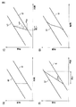
図6は、図1および図2に示したセレクタ14による切り換えと、実施形態の切り換え補間部40による切り換えを説明する図である。
図6では、説明を簡略にするために、第1回転計測器に異常が発生した時の第1回転角速度ω1と第2回転角速度ω2が等しく且つその後一定で、第1回転角度R1および第2回転角度R2が異なるとして説明を行う。さらに、Q1は第1回転角度R1を示し、Q2は第2回転角度R2を示し、0<ω1=ω2=一定であるから、Q1とQ2は単調増加する平行な直線となる。
FIG. 6 is a diagram for explaining switching by the
In FIG. 6, for the sake of simplicity, the first rotation angular velocity ω1 and the second rotation angular velocity ω2 when the abnormality occurs in the first rotation measuring instrument are equal and are constant thereafter, and the first rotation angle R1 and the second rotation angle R The description will be made assuming that the rotation angle R2 is different. Further, Q1 represents the first rotation angle R1, Q2 represents the second rotation angle R2, and 0 <ω1 = ω2 = constant, so that Q1 and Q2 are monotonically increasing parallel straight lines.
図6の(A)は、セレクタ14による切り換えを示す。セレクタ14は、第1検出信号(第1回転角度R1および第1回転角速度ω1)を第2検出信号(第2回転角度R2および第2回転角速度ω2)に切り換えるだけであるから、第1回転角度R1から第2回転角度R2への変化は瞬時に終了する。したがって、この場合の回転角速度の変化は非常に大きい。
FIG. 6A shows switching by the
モータ制御系では、上記のような回転角度の変化が発生すると、制御目標の角度が大きく変化したことになり、目標角度になるように回転角速度を大きく変化させる制御を行う。これに応じて、ドライバ17は、駆動信号を急激に変化させるため、脱調などの悪影響が発生する。また、駆動信号に応じてモータ11の回転速度が急激に変化し、目標回転速度に近づくが、今度は逆に急激に減速するが、イナーシャの関係で目標回転速度を超えて変化し、このような制御を繰り返して目標回転速度に収束することになる。言い換えれば、回転速度が振動しながら目標回転速度に収束する。このように、図1および図2に示したセレクタ14による瞬時の切り換えでは、検出信号を利用する後段に悪影響を及ぼす。
図6の(B)は、元の回転角度Q1から目標回転角度Q2への変化をサーボ制御系の最大許容角速度Δωで変化させる補間処理を行った場合を示す。元の回転角度Q1に対する角速度をΔω増加させる。この場合、モータ制御系の影響は最小で済むが、切り換え時間が長くなる。
In the motor control system, when a change in the rotation angle as described above occurs, the angle of the control target has changed greatly, and control is performed to greatly change the rotation angular velocity so as to be the target angle. In response to this, the
FIG. 6B shows a case where an interpolation process for changing the change from the original rotation angle Q1 to the target rotation angle Q2 at the maximum allowable angular velocity Δω of the servo control system is performed. The angular velocity with respect to the original rotation angle Q1 is increased by Δω. In this case, the influence of the motor control system can be minimized, but the switching time becomes long.
例えば、ドライバ17がモータ11をPWM駆動する時、PWMのキャリア周波数1周期内において指定した制御量(Ang_L)をPWMのキャリア周波数(fc)とモータ回転数(R[rps])から次のように定義する。
Ang_L < 360 x R/fc[°]
このAng_Lの変化量で回転動作したときの角速度をωMAXとする。この角速度ωMAXは、PWM駆動で実現できる最大変化量である。
For example, when the
Ang_L <360 x R / fc [°]
Let ωMAX be the angular velocity when rotating with this Ang_L variation. This angular velocity ωMAX is the maximum change amount that can be realized by PWM drive.
図6の(C)は、元の回転角度Q1から目標回転角度Q2への変化を角速度ωMAXで行った場合を示す。この場合、元の回転角度Q1に対する角速度に加速用角速度Δωを加えてωMAXとする。
ωMAXで切り換えを行えば短時間で切り換えが可能であるが、急にωMAXにしてしまうと、図6の(A)の場合と同様にモータ制御系に悪影響を及ぼす。
FIG. 6C shows a case where the change from the original rotation angle Q1 to the target rotation angle Q2 is performed at the angular velocity ωMAX. In this case, the acceleration angular velocity Δω is added to the angular velocity with respect to the original rotation angle Q1 to obtain ωMAX.
Switching at ωMAX can be performed in a short time, but sudden change to ωMAX will adversely affect the motor control system as in the case of FIG.
図6の(D)は、実施形態のモータ制御システムの切り換え補間部40における補間処理を示す。この補間処理では、元の回転角度Q1から目標回転角度Q2への変化を、角速度を段階的に変化させて行う。図6の(D)では、元の回転角度Q1に対する角速度から、単位処理時間ごとに角速度を少し加速して補間回転角度を算出し、さらに角速度を少し加速して補間回転角度を算出する処理を繰り返す。そして、角速度が上記のωMAXにまで増加すると、ωMAXでの加速を維持しながら単位処理時間ごとに補間回転角度を算出する。補間回転角度が、回転角度Q2に近づくと、角速度をωMAXから減少させ、補間回転角度が、回転角度Q2に一致すると、完全に第2回転計測器の出力に切り換える。
FIG. 6D shows an interpolation process in the switching
図7は、実施形態の切り換え補間部40による切り換え補間処理をより具体的に説明する図である。図6の(D)に示した例では、第1回転計測器に異常が発生した時の第2回転角速度ω2は、その後一定で変化しないとして説明したが、実際にはモータ11の回転に応じて変化する。図7において、Q1は第1回転角度R1の変化を示し、参照番号31で示す時間に異常発生が検出され、第2検出信号(第2回転角度R2および第2回転角速度ω2)への切り換えが開始される。図7では、Q1は角速度が一定であるとして示しているが、参照番号31で示す時間以後どのように変化しても処理には関係しない。Q2は、第2回転角度R2の変化曲線を示し、参照番号31で示す時間において、すでにQ1とは異なる角度となっており、角速度も既に異なっており、その後も変化する。
FIG. 7 is a diagram for more specifically explaining the switching interpolation processing by the switching
図7は、切り換え開始時に第2回転角度R2は第1回転角度R1より大きく、R1を徐々に増加させてR2に一致させ、その後R2に切り換える場合を示している。なお、第3角速度ω3は、参照番号31で示す時間において、ω1からω2に切り換えられ、以下の説明における角速度は回転角度R3を演算する補間処理にのみ関係する。
FIG. 7 shows a case where the second rotation angle R2 is larger than the first rotation angle R1 at the start of switching, and R1 is gradually increased to coincide with R2, and then switched to R2. The third angular velocity ω3 is switched from ω1 to ω2 at the time indicated by
図7において、Fは加速境界角度差の変化曲線を示し、Gは折り返し角度の変化曲線を示し、Hは減速境界角度差の変化曲線を示す。加速境界角度差の変化曲線Fは、切り換え補間処理において、第1回転角度R1から第2回転角度R2に変化させる場合に、角速度を最大角速度ωMAXまで段階的に増加させる時点を示す。折り返し角度の変化曲線Gは、加速境界角度差の変化曲線F上の状態から、最大角速度ωMAXで第2回転角度R2に近づくように加速する範囲の中間となる時点を示す。減速境界角度差の変化曲線Hは、第2回転角度R2に近づいたので、最大角速度ωMAXから第2回転角速度ω2に近づくように減速を開始する時点を示す。回転角度を補間するために、角速度をどの程度増加または減少させるかは、その時点の第2回転角速度ω2に応じて決定する。 In FIG. 7, F indicates a change curve of the acceleration boundary angle difference, G indicates a change curve of the turning angle, and H indicates a change curve of the deceleration boundary angle difference. The change curve F of the acceleration boundary angle difference indicates a time point at which the angular velocity is increased stepwise to the maximum angular velocity ωMAX when changing from the first rotation angle R1 to the second rotation angle R2 in the switching interpolation process. The folding angle change curve G indicates a point in the middle of the range of acceleration from the state on the acceleration boundary angle difference change curve F so as to approach the second rotation angle R2 at the maximum angular velocity ωMAX. Since the change curve H of the deceleration boundary angle difference approaches the second rotation angle R2, it indicates the time point at which deceleration is started so as to approach the second rotation angular velocity ω2 from the maximum angular velocity ωMAX. In order to interpolate the rotation angle, how much the angular velocity is increased or decreased is determined according to the second rotation angular velocity ω2 at that time.
図8は、回転角度補間処理において、第2回転角速度ω2に対して、角速度をどの程度増加または減少する量に設定するかを示す図である。図8に示すように、角速度を増加または減少させる量は、第2回転角速度ω2に比例するように決定する。 FIG. 8 is a diagram showing how much the angular velocity is set to be increased or decreased with respect to the second rotational angular velocity ω2 in the rotational angle interpolation processing. As shown in FIG. 8, the amount by which the angular velocity is increased or decreased is determined to be proportional to the second rotational angular velocity ω2.
次に、回転角度R3をどのように補間処理するかについて、図7の例で詳しく説明する。
補間処理は、参照番号31で示す時間(t1)において開始される。t1の時の第1回転角度R1であり、これが切り換え開始時の補間した第3回転角度R31となる。t1の時、第1回転角度R1より第2回転角度R2の方が進んでいる(プラス)ので、その時点の第2回転角速度ω21より加速してR3を演算する必要がある(加速しないとR2に追いつかない)。図8にしたがって、ω21に対してΔω1増加させるので、切り換え処理開始時のR3を演算する補間処理のための回転角速度ω31はω21+Δω1となる。
Next, how the rotation angle R3 is interpolated will be described in detail with reference to the example of FIG.
The interpolation process starts at time (t1) indicated by
1単位制御周期経過し、参照番号32で示す時間(t2)になると、第3回転角度R32は、R31+(ω21+Δω1)(t2−t1)である。t2の時、第2回転角速度ω2はω22であり、図8にしたがって、ω22に対してさらにΔω2増加させるので、補間処理のための回転角速度ω32はω22+Δω1+Δω2となる。
When one unit control cycle elapses and the time (t2) indicated by
図7では、4回処理を繰り返すことにより、第3回転角度R3は増加し、参照番号33で示す時点で、加速境界角度差の変化曲線Fに到達する。この時点でのR3を増加させる回転角速度ω34はω24+Δω1+Δω2+Δω3+Δω4となる。次に、第3回転角度R3を最大角速度ωMAXで加速するとして演算し、単位制御周期ごとに演算値を出力する。この状態を、第3回転角度R3が減速境界角度差の変化曲線Hに到達するまで維持する。
In FIG. 7, by repeating the process four times, the third rotation angle R <b> 3 increases, and reaches the change curve F of the acceleration boundary angle difference at the time indicated by
参照番号34で示す時間に、第3回転角度R3が減速境界角度差の変化曲線Hに到達すると、補間処理のための回転角速度の最大角速度ωMAXからの減速を開始する。減速の補間処理は、加速の補間処理に類似しており、その時点の回転角速度と第2回転角速度ω2の値から減速する加速度を決定する。
When the third rotation angle R3 reaches the change curve H of the deceleration boundary angle difference at the time indicated by the
以上の処理を繰り返すことで、第3回転角度R3は、第2回転角度R2に近づき、参照番号35で示す時間に、第3回転角度R3は第2回転角度R2に一致する。それ以後は、第2回転角度R2を第3回転角度R3として出力する。
By repeating the above processing, the third rotation angle R3 approaches the second rotation angle R2, and the third rotation angle R3 coincides with the second rotation angle R2 at the time indicated by
以上まとめると、実施形態の切り換え補間部40は、以下の手順で切り換え補間処理を行う。
(1)レゾルバ同士の角度差を求める。
(2)切り換え先の角速度ωからΔωを求める。
(3)角度差の正負状態とΔωとωから補間処理のための切り換え中の算出角速度を求める。
(4)切り換え中の算出角速度が、上限、下限のリミット値になったならリミット値に切り換える。
(5)目標角度に近づいたら上記の(3)の逆方向の演算を行い、切り換え中の算出角速度を求める。
(6)切り換え中の算出角速度を積分する事により算出角度を求める。
(7)以上のようにして、算出角度が切り換わり先のレゾルバ角度に接近していく。
In summary, the switching
(1) An angle difference between resolvers is obtained.
(2) Find Δω from the angular velocity ω at the switching destination.
(3) The calculated angular velocity during switching for the interpolation process is obtained from the positive / negative state of the angle difference and Δω and ω.
(4) If the calculated angular velocity during switching reaches the upper and lower limit values, switch to the limit value.
(5) When approaching the target angle, the calculation in the reverse direction of (3) above is performed to obtain the calculated angular velocity during switching.
(6) The calculated angle is obtained by integrating the calculated angular velocity during switching.
(7) As described above, the calculated angle is switched and approaches the resolver angle of the destination.
図9は、上記の動作を行う切り換え補間部40の回路構成ブロック図である。
切り換え補間部40は、セレクタ41、角度偏差算出部(R1−R2)42と、セレクタ43と、初回保持部44と、角速度算出部45と、角度算出部46と、0〜360°変換部47と、を有する。
FIG. 9 is a block diagram of a circuit configuration of the switching
The switching
セレクタ41は、選択信号SELに応じて、第1回転計測器からの第1回転角度R1と第2回転計測器からの第2回転角度R2の一方を選択して、角度Bとして出力する。選択信号SELは、セレクタ41が、第1回転計測器が正常であればR1を、第1回転計測器が異常であることが検出されるとR2を選択する信号である。
The
角度偏差算出部(R1−R2)42は、R1とR2の差を、異常の発生に備えて常時演算する。
セレクタ43は、選択信号SELに応じて、第1回転計測器からの第1回転角速度ω1と第2回転計測器からの第2回転角速度ω2の一方を選択して、切り換え先角度Bとして出力する。
The angle deviation calculator (R1-R2) 42 constantly calculates the difference between R1 and R2 in preparation for occurrence of an abnormality.
The
初回保持部44は、第1回転計測器に異常が検出され、選択信号SELが切り換わった時、角度偏差算出部(R1−R2)42の出力する角度差R1−R2を保存し、切り換え直後の角度差Cとして出力する。
The
角速度算出部45は、角度差Cと、セレクタ41から出力される切り換え先角度B(切り換え処理中は第2回転角度R2)を受け、切り換え中の算出角速度Sの生成を行う。角速度算出部45は、R1とR2の角度差の補間処理を、モータ制御系への影響がないよう、補間処理の進行状態ごとに区分して行うことにより、切り換え時間の短縮を実現している。また、制御周期毎に切り換え先の角速度ωを確認していくことで、切り換え中に角速度が変化した場合でも追従して角速度を算出していく。
The angular
角度算出部46は、角度差Cと、セレクタ41から出力される第2回転角度R2および角速度算出部45の出力する切り換え中の算出角速度Sを受け、段階的に変化する算出回転角度Aの生成を行う。補間回転角度は、切り換え時間を短縮すると共に、モータ制御系に影響のない角度差で段階的に変化するように補間処理して生成される。また、角度算出部46は、単位制御周期ごとに、切り換え先である第2回転計測器の出力する角速度ω2を確認していくことで、切り換え中に角速度が変化した場合でも追従して角速度を算出していく。また、角度算出部46は、切り換え先である第2回転計測器の出力する回転角度R2と、角速度算出部45が生成した角速度から算出した角速度Sに対して、常に比較、差分を求め、角速度算出部45に切り換え先との角度差(切り換え中角度差)Dとして提供している。
The
0〜360°変換部47は、角度算出部46が求めた回転角度値Aがマイナスや360°を越えている場合、0°から360°の間の値に修正する。
When the rotation angle value A obtained by the
ここで、上記の切り換え補間処理における算出角速度の変化および使用する用語を説明する。 Here, the change of the calculated angular velocity and the terminology used in the switching interpolation process will be described.
図10は、補間処理における算出角速度の変化および補間処理で使用する用語を説明する図である。図10は、図6の(D)で使用した図に対応し、説明を簡単にするため、切り換え先である第2角度計測器の第2回転角度R2と切り換え元の第1角度計測器の第1回転角度R1の変化を直線で示すが、前述のように、実際は常に変動する曲線である。 FIG. 10 is a diagram for explaining a change in the calculated angular velocity in the interpolation process and terms used in the interpolation process. FIG. 10 corresponds to the diagram used in FIG. 6D, and for the sake of simplicity, FIG. 10 shows the second rotation angle R2 of the second angle measuring device that is the switching destination and the first angle measuring device of the switching source. Although the change of the first rotation angle R1 is indicated by a straight line, as described above, it is actually a curve that constantly fluctuates.
・折返し角度
折返し角度とは、切り換え先の角度B(R2)から、切り換え時の角度差Cの1/2の角度異なる角度である。B(R2)が変動している為、下記式より常に補正が掛かる。
折返し角度=B+C/2(R1<R2の時Cは負、R1>R2の時Cは正)
-Turn-back angle The turn-back angle is an angle different from the switching destination angle B (R2) by ½ of the angle difference C at the time of switching. Since B (R2) fluctuates, correction is always applied from the following equation.
Folding angle = B + C / 2 (C is negative when R1 <R2, C is positive when R1> R2)
・加速境界角度差
加速境界角度差とは、切り換え時の角度差Cの補正方向が進みの場合(R1<R2)、切り換え中の角速度SがωMAXに到達したときの角度差とする。例えば、図7に示した例では、4回目の単位制御周期でωMAXに到達したときの例である。
Acceleration boundary angle difference The acceleration boundary angle difference is an angle difference when the angular velocity S during switching reaches ωMAX when the correction direction of the angle difference C at the time of switching is advanced (R1 <R2). For example, the example shown in FIG. 7 is an example when ωMAX is reached in the fourth unit control cycle.
加速境界角度差は、切り換え時の角度差Cの補正方向が遅れの場合(R1>R2)、詳細を後述する減速境界角度差の反対の所にある。但し速度差に差分がある可能性を考慮し、下記補正項を付ける。 The acceleration boundary angle difference is opposite to the deceleration boundary angle difference described in detail later when the correction direction of the angle difference C at the time of switching is delayed (R1> R2). However, considering the possibility that there is a difference in speed difference, add the following correction term.
(ケース1)切り換え時の角度差Cの補正方向が進みの場合(R1<R2)
ωMAX=ω4+Δω1+Δω2+Δω3+Δω4とすると、加速境界角度差=(ω1+Δω1)t1+(ω2+Δω1+Δω2)t2+(ω3+Δω1+Δω2+Δω3)t3+(ω4+Δω1+Δω2+Δω3+Δω4)t4
(Case 1) When the correction direction of the angle difference C at the time of switching is advanced (R1 <R2)
Assuming ωMAX = ω4 + Δω1 + Δω2 + Δω3 + Δω4, acceleration boundary angle difference = (ω1 + Δω1) t1 + (ω2 + Δω1 + Δω2) t2 + (ω3 + Δω1 + Δω2 + Δω3) t3 + (ω4 + Δω1 + Δω2 + Δω3 + Δω4) t4
(ケース2)切り換え時の角度差Cの補正方向が遅れの場合(R1>R2)
加速境界角度差=ω/(ωdm+ωs)/2)
ただし、ωs:切り換え時の第2回転計測器の第2角速度ω2
ωdm:境界角度達成時の切り換え中の角度差Dm到達時の角速度
(Case 2) When the correction direction of the angle difference C at the time of switching is delayed (R1> R2)
Acceleration boundary angle difference = ω / (ωdm + ωs) / 2)
However, ωs: second angular velocity ω2 of the second rotation measuring instrument at the time of switching
ωdm: Angular velocity when reaching the angle difference Dm during switching when the boundary angle is achieved
・減速境界角度差
切り換え時の角度差Cの補正方向が進みの場合、加速境界角度差の反対の所にある。但し速度差に差分がある可能性を考慮し、下記補正項を付ける。
・ Deceleration boundary angle difference When the correction direction of the angle difference C at the time of switching is advanced, it is at the opposite side of the acceleration boundary angle difference. However, considering the possibility that there is a difference in speed difference, add the following correction term.
減速境界角度差とは、切り換え時の角度差Cの補正方向が遅れの場合、切り換え中の角速度SがωMINに到達したときの角度差とする。 The deceleration boundary angle difference is an angle difference when the angular velocity S during switching reaches ωMIN when the correction direction of the angle difference C at the time of switching is delayed.
(ケース1)切り換え時の角度差Cの補正方向が進みの場合(R1<R2)
減速境界角度差=ω/(ωdm+ωs)/2)
ただし、ωs:切り換え時の第2回転計測器の第2角速度ω2
ωdm:境界角度達成時の切り換え中の角度差(Dm)到達時の角速度
(Case 1) When the correction direction of the angle difference C at the time of switching is advanced (R1 <R2)
Deceleration boundary angle difference = ω / (ωdm + ωs) / 2)
However, ωs: second angular velocity ω2 of the second rotation measuring instrument at the time of switching
ωdm: Angular velocity when reaching the angle difference (Dm) during switching when the boundary angle is achieved
(ケース2)切り換え時の角度差Cの補正方向が遅れの場合(R1>R2)
ωMAX=ω4−Δω1−Δω2−Δω3−Δω4とすると、加速境界角度差=(ω1−Δω1)t1+(ω2−Δω1−Δω2)t2+(ω3−Δω1−Δω2−Δω3)t3+(ω4−Δω1−Δω2−Δω3−Δω4)t4
(Case 2) When the correction direction of the angle difference C at the time of switching is delayed (R1> R2)
If ωMAX = ω4-Δω1-Δω2-Δω3-Δω4, the acceleration boundary angle difference = (ω1-Δω1) t1 + (ω2-Δω1-Δω2) t2 + (ω3-Δω1-Δω2-Δω3) t3 + (ω4-Δω1-Δω2- Δω3-Δω4) t4
・算出角度A
算出角度Aとは、この切り換え補間部40の角度算出部46が生成した回転角度のことであり、図10では、Q1からQ2に段階的に変化する線上の折れ曲がった点の示す角度に相当する。
・ Calculated angle A
The calculation angle A is a rotation angle generated by the
・切り換え中の角速度S
切り換え中の角速度Sとは、補間角度を決定していく変位を角速度として表したものである。
切り換え立ち上がりと切り換わり終了では、切り換え先の第2回転計測器の角速度ω2に一致し、折返し角度付近では、最大(最小)角速度になるような曲線で示される。
-Angular velocity S during switching
The angular velocity S during switching represents a displacement that determines an interpolation angle as an angular velocity.
At the start of switching and at the end of switching, it is indicated by a curve that matches the angular velocity ω2 of the second rotation measuring device that is the switching destination and that has the maximum (minimum) angular velocity in the vicinity of the turning angle.
・切り換え時の角度差C
切り換え開始時における、切り換え元の第1回転計測器の回転角度R1と、切り換え先の第2回転計測器の回転角度R2の差である。切り換え時の角度差Cは、切り換わり終了まで、変わらず保持される。
・ Changing angle C
This is the difference between the rotation angle R1 of the first rotation measuring instrument as the switching source and the rotation angle R2 of the second rotation measuring instrument as the switching destination at the start of switching. The angle difference C at the time of switching is held unchanged until the end of switching.
・切り換え先の第2回転計測器の回転角度R2との角度差D
切り換え先の第2回転計測器の回転角度R2と比較した角度差のことである。開始時には、切り換え時の角度差Cと同値であり、切り換わり終了時は”0”になっている。
-Angle difference D from the rotation angle R2 of the second rotation measuring instrument to be switched to
This is the angle difference compared with the rotation angle R2 of the second rotation measuring instrument to be switched to. At the start, it is the same value as the angle difference C at the time of switching, and is “0” at the end of the switching.
・境界角度到達時の切り換え先との角度差Dm
Dm=切り換え直後の角度差C−切り換え先との角度差D
実施形態における切り換え中の算出角度Aの算出の基本原理を、図10と関連付けて説明すると、以下のようになる。
-Angle difference Dm from the switching destination when the boundary angle is reached
Dm = angle difference immediately after switching C−angle difference D from switching destination
The basic principle of calculation of the calculation angle A during switching in the embodiment will be described below in association with FIG.
Q1上の参照番号31で示す切り換え開始の時点から、算出角度Aが加速境界角度差Fに到達するまでは、Q2(R2)の方がQ1(R1)より進んでいるので、サーボ制御に影響しないように徐々に加速し、順次算出角度Aを算出して出力する。算出角度Aが、加速境界角度差Fに到達した時には、算出角速度Sが最大角速度に達しており、加速境界角度差Fと減速境界角度差Hの間は、算出角速度Sを最大角速度に固定して、順次算出角度Aを算出して出力する。したがって、加速境界角度差Fと減速境界角度差Hの間は、高速状態である。その後、算出角度Aが減速境界角度差Hに達すると、減速を行い、算出角度Aが第2回転計測器の出力する第2回転角度R2に一致する時には、算出角速度Sが第2回転計測器の出力する角速度ω2に一致するようにする。
Since Q2 (R2) is advanced from Q1 (R1) until the calculated angle A reaches the acceleration boundary angle difference F from the switching start time indicated by
Q2(R2)の方がQ1(R1)より遅れている時には、上記と逆に、まず減速処理し、最小角速度で進んだ後、加速して、算出角速度Sが第2回転計測器の出力する角速度ω2に一致するようにする。 When Q2 (R2) is later than Q1 (R1), on the contrary, first, deceleration processing is performed, the vehicle proceeds at the minimum angular velocity, then accelerates, and the calculated angular velocity S is output from the second rotation measuring instrument. It matches with the angular velocity ω2.
上記の説明は、切り換え処理中に、算出角速度Sが、最大または最少角速度になる場合であるが、最大または最少角速度になる前に、折返し角度Gに達する場合がある。その場合には、算出角速度Sが、折返し角度Gに達した時に、加速と減速を切り換える。 In the above description, during the switching process, the calculated angular velocity S becomes the maximum or minimum angular velocity, but the turn-back angle G may be reached before the maximum or minimum angular velocity. In that case, when the calculated angular velocity S reaches the turn-back angle G, acceleration and deceleration are switched.
以上説明した用語を用いて、図9の各部を説明する。
図11は、図9の角度算出部46の詳細な構成を示すブロック図である。
角度算出部46は、乗算器51と、時間幅レジスタ52と、減算器53と、角度差保持部54と、初期値算出部55と、減算器56と、初期信号発生部57と、セレクタ58と、角度偏差算出部59と、収束判定部60と、セレクタ61と、を有する。角度算出部46は、算出角度Aの生成と、切り換え先との角度差Dの生成を行う。
Each part of FIG. 9 is demonstrated using the term demonstrated above.
FIG. 11 is a block diagram showing a detailed configuration of the
The
初期値算出部(B−C)55は、切り換え先の回転角度であるBと切り換え時の角度差Cから、切り換え時の第1回転計測器の出力する回転角度R1を算出する。
初期信号発生部57は、選択信号SELに応じて、切り換え時の最初の補間処理を行う間のみ有効になる初期信号を発生する。
The initial value calculator (BC) 55 calculates a rotation angle R1 output from the first rotation measuring instrument at the time of switching from B, which is the rotation angle of the switching destination, and the angle difference C at the time of switching.
In response to the selection signal SEL, the
セレクタ58は、初期信号が有効の期間B側を選択し、それ以外の時にはA側を選択する。したがって、セレクタ58は、切り換え時の最初の補間処理のみR1を、それ以後は減算器56が出力するその時点の角度差を、切り換え中の角度Iとして出力する。
The
角度偏差算出部(B−I)59は、切り換え先の回転角度であるBと切り換え中の角度Iの差を算出して切り換え中の角度差Dとして出力する。 An angle deviation calculation unit (BI) 59 calculates the difference between B, which is the rotation angle of the switching destination, and the angle I being switched, and outputs it as the angle difference D being switched.
判定部60は、セレクタ60の切り換え信号を出力する。この切り換え信号は、セレクタ60が、初期および収束後にはB側を、その間はA側を選択して算出角度Aとして出力するように制御する。判定部60は、切り換え中の角度差Dがあらかじめ設定した範囲に収束したかを判定する。これにより算出誤差による角度収束が不完全な場合でも、算出角度はB、すなわちR2に切り換えられる。
The
乗算器51は、切り換え中の算出角速度Sに、時間幅レジスタ52に保持された単位制御周期Tを乗算し、単位制御周期Tの間の回転角度を算出する。
減算器53は、角度差保持部54に保持された前回の角度差から乗算器51の出力する回転角度量を減算し、その時点の角度差を算出する。
The
The
角度差保持部54は、切り換え開始時には、角度差Cを保持し、それ以後減算器53の出力するその時点の角度差を保持するように保持する値を更新する。
減算器56は、切り換え先の回転角度R1から減算器53の出力するその時点の角度差を減算し、その時点の算出角度を求める。
The angle
The
以上の通り、前回の角度差から、単位制御周期Tの間の算出角速度Sに対応する回転量を減算していくことで、その時点の算出角度を求める。このようにして求められたその時点の算出角度は、補間切り換え処理中、セレクタ58およびセレクタ61を介して算出角度Aとして出力され、収束すると、算出角度Aとして切り換え先の回転角度R2が出力される。
As described above, by subtracting the rotation amount corresponding to the calculated angular velocity S during the unit control period T from the previous angle difference, the calculated angle at that time is obtained. The calculated angle obtained at this time is output as the calculated angle A through the
図12は、図9の角速度算出部45の詳細な構成を示すブロック図である。角速度算出部45は、切り換え中の算出角速度Sの生成を行い、切り換え中の算出角速度Sを、加速状態、高速状態、減速状態のように変化させることで、モータ制御系の影響がでない、切り換え時間の短縮を実現している。
FIG. 12 is a block diagram showing a detailed configuration of the angular
角速度算出部45は、折返し角度抽出部71と、初回角速度保持部72と、反転境界角度差生成部73と、制御判定部74と、ω−Δωテーブル75と、加減算器76と、前回値保持部77と、加算器78と、最大値最小値保持部79と、セレクタ80と、を有する。
The angular
折返し角度抽出部71および反転境界角度差生成部73については後述する。
初回角速度保持部72は、選択切り換え信号SELAに応じて、切り換え時の切り換え先の第2回転計測器の出力する回転角速度ω2をラッチして初回角速度ωsとして保持する。
The folding
In response to the selection switching signal SELA, the initial angular
ω−Δωテーブル75は、図8の関係を記憶したテーブルで、ω2からΔωを生成する。これは、角速度によりモータ制御系に影響のないΔωが異なることが予想されるためである。また、角速度ωは、制御単位ごとに新しい値を使用するようにしており、これにより、切り換え中に角速度ωが変化した場合にも追従できる。 omega-[Delta] [omega table 7 5 is a table storing the relationship of FIG. 8, to produce a [Delta] [omega from .omega.2. This is because Δω that does not affect the motor control system is expected to vary depending on the angular velocity. Further, the angular velocity ω uses a new value for each control unit, so that it can follow even when the angular velocity ω changes during switching.
加減算器76は、Δωと前回値保持部77に保持された前回の角速度から新たな加速度を算出する。単位制御周期TごとにΔωを加算してゆくことで、加速状態から高速状態に近づけてゆく。なお、減速の場合はマイナスの値を加算する。このように、加減算器76と前回値保持部77は、Δω1、Δω1+Δω2、Δω1+Δω2+・・・を順次生成する。加減算器76の演算が、加算か減算かの制御は、制御判定部74が行う。
The adder /
加算器78は、ωとΔω1+Δω2+・・・を足し合わせる。
以上のようにして、加速期間中と減速期間中の角速度を生成する。
The
As described above, the angular velocity during the acceleration period and during the deceleration period is generated.
最大値最小値保持部79は、モータ制御での最大値ωMAXおよび最小値ωMINを保持し、R2がR1より進んでいる時には最大値ωMAXを、R2がR1より遅れている時には最小値ωMINを、出力する。
The maximum value / minimum
制御判定部74は、前述の加減算器76の制御およびセレクタ80における切り換え中の算出角速度Sの選択制御を行う。
The
セレクタ80は、制御判定部74の制御に基づいて、ω+Δω1+Δω2+・・・と最大値(最小値)のいずれかを選択し、切り換え中の算出角速度Sとして出力する。
The
反転境界角度差生成部73は、後述する図13の構成を有し、角速度の変化に合わせて減速又は加速境界角度差の生成を行う。例えば、高速状態から減速状態への推移であれば、減速境界角度差の生成を行う。切り換え中の角度差が減速境界角度を達成すると、減速を開始する。
The inversion boundary angle
折返し角度抽出部71は、後述する図14の構成を有し、折返し角度の生成を行う。
図13は、反転境界角度差生成部73の構成を示す図である。
反転境界角度差生成部73は、ωdm抽出部81と、境界角度達成監視部82と、平均算出部83と、除算器84と、減算器85と、乗算器86と、を有する。
The folding
FIG. 13 is a diagram illustrating a configuration of the inversion boundary angle
The inversion boundary angle
境界角度達成監視部82は、切り換え中の角度差Dmが境界角度に到達したかを監視し、到達すると到達信号を出力する。
ωdm抽出部81は、第2回転計測器の出力する第2回転角速度ω2を監視し、到達信号が出力された時の第2回転角速度ωdmを抽出する。
The boundary angle
The
平均算出部83は、第2回転角速度ω2の切り換え開始時の角速度ωsとωdmの平均(ωdm+ωs)/2を算出する。
除算器84は、第2回転角速度ω2を上記の平均(ωdm+ωs)/2で除して、前述の補正項を算出する。
The
The
減算器85は、切り換え時の角度差CからDmを減じて加速(減速)境界角度差を算出する。
乗算器86は、加速(減速)境界角度差に補正項を乗じて、加速(減速)境界角度差を算出し、反転境界角度Ddとして出力する。
The
The
図14は、折返し角度抽出部71の構成を示す図である。折返し角度抽出部71は、折返し角度の生成を行う。
折返し角度抽出部71は、切り換え時の角度差Cの1/2を算出する1/2算出部87と、1/2算出部87の出力と切り換え先の角度Bを加算する加算器88と、を有する。
FIG. 14 is a diagram illustrating a configuration of the turn-back
The folding
図15および図16は、図12の制御判定部74の制御フローを示すフローチャートである。図15および図16を参照して制御判定部74の制御を説明する。
制御判定部74に入力する信号は、次の5つである。
15 and 16 are flowcharts showing a control flow of the
The following five signals are input to the
切り換え中の角度差D
切り換え時の角度差C
切り換え中の算出角速度S
切り換え先の角速度ω2
反転境界角度差Dd
Angular difference D during switching
Angle difference C at the time of switching
Calculated angular velocity S during switching
Angular velocity ω2 to switch to
Inversion boundary angle difference Dd
また、制御判定部74からの出力情報は、次の2つである。
セレクタ80の選択信号(加速、減速、最大速度切り換え、最小速度切り換え)
加減算器76の制御信号。
Further, the output information from the
Selection signal for selector 80 (acceleration, deceleration, maximum speed switching, minimum speed switching)
Control signal for the adder /
また、制御判定部74で、境界角度達成時の切り換え先との角度差Dmが生成される。
ステップS11では、切り換え時の角度差Cから補正方向が、進み方向であるか遅れ方向であるか判定し、進み方向であればステップS12に進み、遅れ方向であればステップS41に進む。
Further, the
In step S11, it is determined from the angle difference C at the time of switching whether the correction direction is the advance direction or the delay direction. If it is the advance direction, the process proceeds to step S12, and if it is the delay direction, the process proceeds to step S41.
ステップS12では、切り換え中の角度差Dと、加速境界角度、折返し角度および減速境界角度との比較、および角速度と最大角速度との比較を行う。加速境界角度に達していなければステップS13に進む。加速境界角度に達しているが、折返し角度に到達していればステップS21に進む。すでに最大角速度ωMAXを超えて一定の角速度になっていればS12に戻る。減速境界角度(反転境界限界角度差Dd)に達していれば、ステップS31に進む。 In step S12, the angle difference D during switching is compared with the acceleration boundary angle, the turning angle, and the deceleration boundary angle, and the angular velocity is compared with the maximum angular velocity. If the acceleration boundary angle has not been reached, the process proceeds to step S13. If the acceleration boundary angle has been reached but the turn-back angle has been reached, the process proceeds to step S21. If the angular velocity has already exceeded the maximum angular velocity ωMAX and has reached a constant angular velocity, the process returns to S12. If the deceleration boundary angle (reverse boundary limit angle difference Dd) has been reached, the process proceeds to step S31.
ステップS13では、その時点の第2回転角速度ω2にΔωnを加えて(加速して)、切り換え中の算出角速度Sを生成する。
ステップS14では、切り換え中の算出角速度Sが最大値に達したかを判定し、達していればステップS15に進み、達していなければS12に戻る。
In step S13, Δωn is added (accelerated) to the second rotational angular velocity ω2 at that time to generate a calculated angular velocity S during switching.
In step S14, it is determined whether the calculated angular velocity S during switching has reached the maximum value. If it has reached, the process proceeds to step S15, and if not, the process returns to S12.
ステップS15では、加速度境界角度に到達したと決定する。
ステップS16では、切り換え中の角度差Dを、加速度境界角度到達時の切り換え中の角度Dmとして決定する。
In step S15, it is determined that the acceleration boundary angle has been reached.
In step S16, the switching angle difference D is determined as the switching angle Dm when the acceleration boundary angle is reached.
ステップS17では、切り換え中の算出角速度Sを最大値(ωMAX)に切り換え、S12に戻る。
ステップS21では、切り換え中の算出角速度Sが最大値(ωMAX)に達しているか判定し、達していればS12に戻り、達しておらず加速中であればステップS22に進む。
In step S17, the calculated angular velocity S being switched is switched to the maximum value (ωMAX), and the process returns to S12.
In step S21, it is determined whether or not the calculated angular velocity S during switching has reached the maximum value (ωMAX). If it has reached, the process returns to S12, and if not reached, the process proceeds to step S22.
ステップS22では、減速境界角度差を、折返し角度と同じ位置に設定する。
ステップS23では、その時点の第2回転角速度ω2からΔωnを減じて(減速して)、切り換え中の算出角速度Sを生成し、S12に戻る。
In step S22, the deceleration boundary angle difference is set to the same position as the turning angle.
In step S23, Δωn is subtracted (decelerated) from the second rotational angular velocity ω2 at that time to generate a calculated angular velocity S during switching, and the process returns to S12.
ステップS31では、切り換え中の算出角速度Sに対して減速処理に切り換える。
ステップS32では、その時点の第2回転角速度ω2からΔωnを減じて(減速して)、切り換え中の算出角速度Sを生成する。
In step S31, the calculation angular speed S being switched is switched to a deceleration process.
In step S32, Δωn is subtracted (decelerated) from the second rotational angular velocity ω2 at that time, and the calculated angular velocity S being switched is generated.
ステップS33では、切り換え中の算出角速度Sが第2回転計測器の出力するω2に等しいか、切り換え中の角度差D=0であるか判定し、S=ω2またはD=0であればステップS34に進み、S≠ω2またはD≠0であればS12に戻る。 In step S33, it is determined whether the calculated angular velocity S during switching is equal to ω2 output from the second rotation measuring instrument or the angle difference D during switching D = 0. If S = ω2 or D = 0, step S34 is performed. If S ≠ ω2 or D ≠ 0, the process returns to S12.
一方、ステップS11で遅れ方向と判定された場合には、ステップS41に進む。
ステップS41では、切り換え中の角度差Dと、減速境界角度、折返し角度および加速境界角度との比較、および角速度と最小角速度との比較を行う。減速境界角度に達していなければステップS42に進む。減速境界角度に達しているが、折返し角度に到達していればステップS51に進む。すでに最小角速度ωMINを超えて一定の角速度になっていればS41に戻る。加速限界角度(反転境界角度差Dd)に達していれば、ステップS61に進む。
On the other hand, if it is determined in step S11 that the direction is delayed, the process proceeds to step S41.
In step S41, the angle difference D being switched is compared with the deceleration boundary angle, the turning angle, and the acceleration boundary angle, and the angular velocity is compared with the minimum angular velocity. If the deceleration boundary angle has not been reached, the process proceeds to step S42. If the deceleration boundary angle has been reached but the turn-back angle has been reached, the process proceeds to step S51. If the angular velocity already exceeds the minimum angular velocity ωMIN and reaches a certain angular velocity, the process returns to S41. If the acceleration limit angle (reverse boundary angle difference Dd) has been reached, the process proceeds to step S61.
ステップS42では、その時点の第2回転角速度ω2からΔωnを減じて(減速して)、切り換え中の算出角速度Sを生成する。
ステップS43では、切り換え中の算出角速度Sが最小値に達したかを判定し、達していればステップS44に進み、達していなければS41に戻る。
In step S42, Δωn is subtracted (decelerated) from the second rotational angular velocity ω2 at that time, and the calculated angular velocity S being switched is generated.
In step S43, it is determined whether the calculated angular velocity S during switching has reached the minimum value. If it has reached, the process proceeds to step S44, and if not, the process returns to S41.
ステップS44では、減速度境界角度に到達したと決定する。
ステップS45では、切り換え中の角度差Dを、減速度境界角度到達時の切り換え中の角度Dmとして決定する。
In step S44, it is determined that the deceleration boundary angle has been reached.
In step S45, the switching angle difference D is determined as the switching angle Dm when the deceleration boundary angle is reached.
ステップS46では、切り換え中の算出角速度Sを最小値(ωMIN)に切り換え、S41に戻る。
ステップS51では、切り換え中の算出角速度Sが最小値(ωMIN)に達しているか判定し、達していればS41に戻り、達しておらず減速中であればステップS52に進む。
In step S46, the calculated angular velocity S being switched is switched to the minimum value (ωMIN), and the process returns to S41.
In step S51, it is determined whether or not the calculated angular velocity S during switching has reached the minimum value (ωMIN). If it has reached, the process returns to S41, and if not, the process proceeds to step S52.
ステップS52では、加速境界角度差を、折返し角度と同じ位置に設定する。
ステップS53では、その時点の第2回転角速度ω2にΔωnを加えて(加速して)、切り換え中の算出角速度Sを生成し、S41に戻る。
In step S52, the acceleration boundary angle difference is set to the same position as the turning angle.
In step S53, Δωn is added (accelerated) to the second rotational angular velocity ω2 at that time to generate a calculated angular velocity S during switching, and the process returns to S41.
ステップS61では、切り換え中の算出角速度Sに対して加速処理に切り換える。
ステップS62では、その時点の第2回転角速度ω2にΔωnを加えて(加速して)、切り換え中の算出角速度Sを生成する。
In step S61, the calculation angular speed S being switched is switched to acceleration processing.
In step S62, Δωn is added (accelerated) to the second rotational angular velocity ω2 at that time to generate the calculated angular velocity S being switched.
ステップS63では、切り換え中の算出角速度Sが第2回転計測器の出力するω2に等しいか、切り換え中の角度差D=0であるか判定し、S=ω2またはD=0であればステップS64に進み、S≠ω2またはD≠0であればS41に戻る。 In step S63, it is determined whether the calculated angular velocity S being switched is equal to ω2 output from the second rotation measuring instrument or the angle difference D = 0 being switched. If S = ω2 or D = 0, step S64 is determined. If S ≠ ω2 or D ≠ 0, the process returns to S41.
以上説明した図15および図16のフローチャートで、R2がR1より進んでいる時で、加速状態の時にはS12、S13からS17を行い、高速状態ではS12から直接S12に戻り、減速状態ではS12、S31からS34を行う。R2がR1より遅れている時で、減速状態の時にはS41、S42からS46を行い、低速状態ではS41から直接S41に戻り、加速状態ではS41、S61からS64を行う。 In the flowcharts of FIGS. 15 and 16 described above, when R2 is ahead of R1, S12 and S13 to S17 are performed in the acceleration state, S12 is directly returned to S12 in the high speed state, and S12 and S31 are in the deceleration state. To S34. When R2 is behind R1, when it is in a deceleration state, S41, S42 to S46 are performed, in a low speed state, it returns directly from S41 to S41, and in an acceleration state, S41, S61 to S64 are performed.
切り換え補間部は、ハードウエア回路で実現しても、コンピュータやDSPなどを利用したソフトウエア処理で実現してもよい。 The switching interpolation unit may be realized by a hardware circuit or a software process using a computer or a DSP.
以上説明した実施形態の角度検出装置によれば、複数の回転計測器(レゾルバ)で同一回転軸の回転を計測し、一方に異常が発生した時には他方に切り換える冗長構成で、出力信号を利用する制御系への影響が小さい形で高速に切り換える。これにより、モータ制御系は、設計変更せずに、これまでの制御シーケンスがそのまま使用でき、高速回転し、回転速度が随時変化する回転体にも適用できる。 According to the angle detection device of the embodiment described above, the output signal is used in a redundant configuration in which the rotation of the same rotation shaft is measured by a plurality of rotation measuring devices (resolvers) and one of the rotations is switched to the other when an abnormality occurs. Switch at high speed with minimal impact on the control system. Thus, the motor control system can be used as it is without changing the design, and can be applied to a rotating body that rotates at a high speed and changes its rotation speed as needed.
以上、実施形態を説明したが、ここに記載したすべての例や条件は、発明および技術に適用する発明の概念の理解を助ける目的で記載されたものである。特に記載された例や条件は発明の範囲を制限することを意図するものではなく、明細書のそのような例の構成は発明の利点および欠点を示すものではない。発明の実施形態を詳細に記載したが、各種の変更、置き換え、変形が発明の精神および範囲を逸脱することなく行えることが理解されるべきである。 The embodiment has been described above, but all examples and conditions described herein are described for the purpose of helping understanding of the concept of the invention applied to the invention and technology. In particular, the examples and conditions described are not intended to limit the scope of the invention, and the construction of such examples in the specification does not indicate the advantages and disadvantages of the invention. Although embodiments of the invention have been described in detail, it should be understood that various changes, substitutions and modifications can be made without departing from the spirit and scope of the invention.
11 モータ
12A、12B レゾルバ
13A、13B レゾルバインターフェース
15 CPU
16 モータ制御部
17 ドライバ
18 以上監視部
19 以上検出部
40 切り換え補間部
45 角速度算出部
46 角度算出部
74 制御判定部
11
16
Claims (10)
前記回転体の回転角度に関する第2角度信号および第2角速度信号を出力する第2の回転計測器と、
前記第1および第2の回転計測器における信号を監視し、前記第1の回転計測器の異常発生および前記第2の回転計測器の異常発生を検出する異常検出部と、
前記第1角度信号および前記第1角速度信号を含む第1の組と、前記第2角度信号および前記第2角速度信号を含む第2の組の一方を選択して第3角度信号および第3角速度信号として出力し、前記第1の回転計測器が正常である時には、前記第1角度信号および前記第1角速度信号を選択して前記第3角度信号および前記第3角速度信号として出力し、前記第1の回転計測器に異常が発生した時に、前記第2の回転計測器が正常であれば、前記第1角度信号と前記第2角度信号の差を段階的に縮小するように補間しながら、前記第2角度信号および前記第2角速度信号を前記第3角度信号および前記第3角速度信号として出力するように切り換える切り換え補間部と、を有することを特徴とする角度検出装置。 A first rotation measuring device that outputs a first angle signal and a first angular velocity signal related to the rotation angle of the rotating body;
A second rotation measuring device that outputs a second angle signal and a second angular velocity signal related to the rotation angle of the rotating body;
An abnormality detection unit that monitors signals in the first and second rotation measuring devices and detects the occurrence of an abnormality in the first rotation measuring device and the occurrence of an abnormality in the second rotation measuring device;
One of the first set including the first angular signal and the first angular velocity signal and the second set including the second angular signal and the second angular velocity signal are selected to select a third angular signal and a third angular velocity. When the first rotation measuring instrument is normal, the first angular signal and the first angular velocity signal are selected and output as the third angular signal and the third angular velocity signal, If an abnormality occurs in one rotation measuring instrument and the second rotation measuring instrument is normal, while interpolating to reduce the difference between the first angle signal and the second angle signal stepwise, An angle detection apparatus comprising: a switching interpolation unit configured to switch the second angle signal and the second angular velocity signal to be output as the third angle signal and the third angular velocity signal.
第2の回転計測器により、前記回転体の回転角度を検出し、第2角度信号および第2角速度信号を生成し、
前記第1および第2の回転計測器における信号を監視し、前記第1の回転計測器の異常発生および前記第2の回転計測器の異常発生を検出し、
前記第1の回転計測器が正常である時には、前記第1角度信号および前記第1角速度信号を第3角度信号および第3角速度信号として出力し、
前記第1の回転計測器の異常発生を検出した時に、前記第2の回転計測器が正常であれば、前記第1角度信号と前記第2角度信号の差を段階的に縮小するように補間しながら、前記第2角度信号および前記第2角速度信号を前記第3角度信号および前記第3角速度信号として出力するように切り換える、ことを特徴とする角度検出方法。 The first rotation measuring instrument detects the rotation angle of the rotating body, generates a first angle signal and a first angular velocity signal,
The second rotation measuring instrument detects the rotation angle of the rotating body, generates a second angle signal and a second angular velocity signal,
Monitoring signals in the first and second rotation measuring devices to detect the occurrence of abnormality in the first rotation measuring device and the occurrence of abnormality in the second rotation measuring device;
When the first rotation measuring instrument is normal, the first angle signal and the first angular velocity signal are output as a third angle signal and a third angular velocity signal,
If the second rotation measuring instrument is normal when an abnormality occurrence of the first rotation measuring instrument is detected, interpolation is performed so as to reduce the difference between the first angle signal and the second angle signal stepwise. However, the angle detection method is characterized in that the second angle signal and the second angular velocity signal are switched so as to be output as the third angle signal and the third angular velocity signal.
Priority Applications (2)
| Application Number | Priority Date | Filing Date | Title |
|---|---|---|---|
| JP2013189551A JP6107557B2 (en) | 2013-09-12 | 2013-09-12 | Angle detection device and angle detection method |
| US14/473,690 US9678097B2 (en) | 2013-09-12 | 2014-08-29 | Angle detection device and angle detection method |
Applications Claiming Priority (1)
| Application Number | Priority Date | Filing Date | Title |
|---|---|---|---|
| JP2013189551A JP6107557B2 (en) | 2013-09-12 | 2013-09-12 | Angle detection device and angle detection method |
Publications (3)
| Publication Number | Publication Date |
|---|---|
| JP2015055567A JP2015055567A (en) | 2015-03-23 |
| JP2015055567A5 JP2015055567A5 (en) | 2016-05-19 |
| JP6107557B2 true JP6107557B2 (en) | 2017-04-05 |
Family
ID=52626382
Family Applications (1)
| Application Number | Title | Priority Date | Filing Date |
|---|---|---|---|
| JP2013189551A Expired - Fee Related JP6107557B2 (en) | 2013-09-12 | 2013-09-12 | Angle detection device and angle detection method |
Country Status (2)
| Country | Link |
|---|---|
| US (1) | US9678097B2 (en) |
| JP (1) | JP6107557B2 (en) |
Families Citing this family (10)
| Publication number | Priority date | Publication date | Assignee | Title |
|---|---|---|---|---|
| WO2017104290A1 (en) * | 2015-12-15 | 2017-06-22 | 日立オートモティブシステムズ株式会社 | Vehicle control device |
| CA2945997C (en) * | 2015-12-16 | 2023-05-23 | Rosemount Aerospace Inc. | Static reference resolver circuit |
| CN105509619B (en) * | 2016-01-11 | 2018-01-30 | 云南中烟工业有限责任公司 | A kind of nozzle angle adjusts measurement apparatus |
| JP6665718B2 (en) * | 2016-07-08 | 2020-03-13 | オムロン株式会社 | Motor control device and gaming machine |
| CN106568374A (en) * | 2016-10-20 | 2017-04-19 | 安徽江淮汽车集团股份有限公司 | Transmission shaft angle measurement device |
| JP6782942B2 (en) * | 2016-11-14 | 2020-11-11 | 多摩川精機株式会社 | Detector |
| JP6542304B2 (en) * | 2017-08-10 | 2019-07-10 | 本田技研工業株式会社 | Control device and control method of rotating electric machine |
| JP6863195B2 (en) | 2017-09-19 | 2021-04-21 | トヨタ自動車株式会社 | Drive device |
| CN111338320B (en) * | 2020-03-11 | 2023-03-28 | 西安应用光学研究所 | Stabilized platform fault protection system and method |
| EP4001839A1 (en) * | 2020-11-17 | 2022-05-25 | Leica Geosystems AG | Scanning device for scanning an environment and enabling an identification of scanned moving objects |
Family Cites Families (13)
| Publication number | Priority date | Publication date | Assignee | Title |
|---|---|---|---|---|
| JPH0968439A (en) | 1995-08-31 | 1997-03-11 | Tamagawa Seiki Co Ltd | Output method for resolver/digital conversion |
| JPH09273942A (en) | 1996-02-05 | 1997-10-21 | Aisin Seiki Co Ltd | Method for interpolating sensor output |
| US6507713B2 (en) * | 2000-03-27 | 2003-01-14 | Ricoh Company, Ltd. | Image-formation apparatus, controlling method thereof and image-formation method |
| JP2002081961A (en) * | 2000-09-07 | 2002-03-22 | Koyo Seiko Co Ltd | Rotary angle detector, brushless motor and motor operated power steering system |
| JP3661595B2 (en) | 2001-02-22 | 2005-06-15 | トヨタ自動車株式会社 | Abnormality detection apparatus and abnormality detection method for measuring apparatus |
| JP2005003620A (en) | 2003-06-13 | 2005-01-06 | Toyota Motor Corp | Magnetic position detector |
| JP2005114442A (en) | 2003-10-06 | 2005-04-28 | Hitachi Ltd | Resolver/digital converter with failure detection function |
| JP4294558B2 (en) | 2004-08-23 | 2009-07-15 | ソニー株式会社 | Angle detection signal processor |
| JPWO2006080513A1 (en) * | 2005-01-31 | 2008-06-19 | 株式会社ニコン | Laser light source control method, laser light source device, and exposure apparatus |
| JP4476321B2 (en) | 2007-12-21 | 2010-06-09 | 日本航空電子工業株式会社 | RD converter and angle detection device |
| JP2009210281A (en) | 2008-02-29 | 2009-09-17 | Toyota Motor Corp | Redundancy type rotating angle detection device |
| JP5481236B2 (en) * | 2010-03-10 | 2014-04-23 | Ntn株式会社 | Electric vehicle motor drive system |
| JP5827812B2 (en) * | 2011-03-28 | 2015-12-02 | ミネベア株式会社 | Angle detector |
-
2013
- 2013-09-12 JP JP2013189551A patent/JP6107557B2/en not_active Expired - Fee Related
-
2014
- 2014-08-29 US US14/473,690 patent/US9678097B2/en active Active
Also Published As
| Publication number | Publication date |
|---|---|
| US9678097B2 (en) | 2017-06-13 |
| JP2015055567A (en) | 2015-03-23 |
| US20150073745A1 (en) | 2015-03-12 |
Similar Documents
| Publication | Publication Date | Title |
|---|---|---|
| JP6107557B2 (en) | Angle detection device and angle detection method | |
| JP6272508B2 (en) | Angular error correction device and angular error correction method for position detector | |
| JP5510842B2 (en) | Three-phase motor control device, three-phase motor system, three-phase motor control method and program | |
| JP6005781B2 (en) | Resolver device | |
| JP2015055567A5 (en) | ||
| JP6045768B1 (en) | AC rotating machine control device | |
| JP5194838B2 (en) | Method for estimating magnetic pole position of AC synchronous motor | |
| JP5449569B2 (en) | Motor control device | |
| JP2020005406A (en) | Motor controller | |
| JP2013238431A (en) | Resolver device | |
| JP5845433B2 (en) | Motor drive device | |
| JP2019086451A (en) | Semiconductor device, angle value correcting circuit, and method | |
| JP5447315B2 (en) | AC motor controller | |
| JP4037392B2 (en) | Anomaly detection device | |
| JP2009095154A (en) | Motor controller and its speed detection method | |
| JP7200560B2 (en) | Servo controller and servo system | |
| JP2003319682A (en) | Controller for permanent magnet synchronous motor | |
| JP2010268567A (en) | Controller for ac motor | |
| US10982977B2 (en) | Pulse signal generator and angle detection system including the same | |
| JP4998788B2 (en) | Speed detection device | |
| KR102399652B1 (en) | Resolver signal processing device, drive device, resolver signal processing method, and program | |
| JP7225621B2 (en) | Servo controller | |
| JP5018793B2 (en) | Rotational speed measuring device | |
| JP2007114165A (en) | Device and method for detecting position of moving object | |
| JP4952631B2 (en) | Speed detection device |
Legal Events
| Date | Code | Title | Description |
|---|---|---|---|
| A711 | Notification of change in applicant |
Free format text: JAPANESE INTERMEDIATE CODE: A712 Effective date: 20150612 |
|
| A521 | Request for written amendment filed |
Free format text: JAPANESE INTERMEDIATE CODE: A523 Effective date: 20160328 |
|
| A621 | Written request for application examination |
Free format text: JAPANESE INTERMEDIATE CODE: A621 Effective date: 20160328 |
|
| A977 | Report on retrieval |
Free format text: JAPANESE INTERMEDIATE CODE: A971007 Effective date: 20170125 |
|
| TRDD | Decision of grant or rejection written | ||
| A01 | Written decision to grant a patent or to grant a registration (utility model) |
Free format text: JAPANESE INTERMEDIATE CODE: A01 Effective date: 20170207 |
|
| A61 | First payment of annual fees (during grant procedure) |
Free format text: JAPANESE INTERMEDIATE CODE: A61 Effective date: 20170220 |
|
| R150 | Certificate of patent or registration of utility model |
Ref document number: 6107557 Country of ref document: JP Free format text: JAPANESE INTERMEDIATE CODE: R150 |
|
| LAPS | Cancellation because of no payment of annual fees |