JP4294558B2 - Angle detection signal processor - Google Patents
Angle detection signal processor Download PDFInfo
- Publication number
- JP4294558B2 JP4294558B2 JP2004242664A JP2004242664A JP4294558B2 JP 4294558 B2 JP4294558 B2 JP 4294558B2 JP 2004242664 A JP2004242664 A JP 2004242664A JP 2004242664 A JP2004242664 A JP 2004242664A JP 4294558 B2 JP4294558 B2 JP 4294558B2
- Authority
- JP
- Japan
- Prior art keywords
- signal
- angle
- phase
- unit
- data
- Prior art date
- Legal status (The legal status is an assumption and is not a legal conclusion. Google has not performed a legal analysis and makes no representation as to the accuracy of the status listed.)
- Expired - Fee Related
Links
Images


Classifications
-
- G—PHYSICS
- G01—MEASURING; TESTING
- G01D—MEASURING NOT SPECIALLY ADAPTED FOR A SPECIFIC VARIABLE; ARRANGEMENTS FOR MEASURING TWO OR MORE VARIABLES NOT COVERED IN A SINGLE OTHER SUBCLASS; TARIFF METERING APPARATUS; MEASURING OR TESTING NOT OTHERWISE PROVIDED FOR
- G01D5/00—Mechanical means for transferring the output of a sensing member; Means for converting the output of a sensing member to another variable where the form or nature of the sensing member does not constrain the means for converting; Transducers not specially adapted for a specific variable
- G01D5/12—Mechanical means for transferring the output of a sensing member; Means for converting the output of a sensing member to another variable where the form or nature of the sensing member does not constrain the means for converting; Transducers not specially adapted for a specific variable using electric or magnetic means
- G01D5/244—Mechanical means for transferring the output of a sensing member; Means for converting the output of a sensing member to another variable where the form or nature of the sensing member does not constrain the means for converting; Transducers not specially adapted for a specific variable using electric or magnetic means influencing characteristics of pulses or pulse trains; generating pulses or pulse trains
- G01D5/245—Mechanical means for transferring the output of a sensing member; Means for converting the output of a sensing member to another variable where the form or nature of the sensing member does not constrain the means for converting; Transducers not specially adapted for a specific variable using electric or magnetic means influencing characteristics of pulses or pulse trains; generating pulses or pulse trains using a variable number of pulses in a train
-
- H—ELECTRICITY
- H03—ELECTRONIC CIRCUITRY
- H03M—CODING; DECODING; CODE CONVERSION IN GENERAL
- H03M1/00—Analogue/digital conversion; Digital/analogue conversion
- H03M1/12—Analogue/digital converters
- H03M1/48—Servo-type converters
- H03M1/485—Servo-type converters for position encoding, e.g. using resolvers or synchros
Description
本発明は、レゾルバの角度検出信号を処理して角度データを求める角度検出信号処理装置に関するものである。 The present invention relates to an angle detection signal processing apparatus that processes angle detection signals of a resolver to obtain angle data.
様々な機械装置において、回転軸や可動部の位置情報を知ることは最も基本的な機能である。例えば電動機において、回転子に最適なトルクを与えるためには、回転子の位置に応じた最適な回転磁界を発生するように制御を行う必要がある。例えば自動車関連ではハイブリッドカーの電動機やパワーステアリング等において高信頼性、低コストの角度センサが求められている。また、このような角度センサは、パワーショベル等の土木建築機材や様々な工作機械、製造設備、更には航空宇宙関係と、その応用が極めて多岐に渡る。 In various mechanical devices, it is the most basic function to know the position information of the rotating shaft and the movable part. For example, in an electric motor, in order to give an optimum torque to the rotor, it is necessary to perform control so as to generate an optimum rotating magnetic field according to the position of the rotor. For example, for automobiles, high-reliability and low-cost angle sensors are required for electric motors and power steering of hybrid cars. Such angle sensors have a wide variety of applications, such as civil engineering and construction equipment such as power shovels, various machine tools, manufacturing equipment, and aerospace.
角度を検出し制御する方法は、極めて多様な方法が考案されている。例えば最も簡単な角度の制御には、ステッピングモータが用いられる。これは、回転に伴って発生するパルスの数を角度の情報として用いるものである。しかしながら、ステッピングモータを用いる方法は、回転にスリップが起こるとステッピングモータ自身でそれを検知することができないため、信頼性が高いとはいえない。 Various methods have been devised for detecting and controlling the angle. For example, a stepping motor is used for the simplest angle control. This uses the number of pulses generated as a result of rotation as angle information. However, the method using the stepping motor cannot be said to have high reliability because the stepping motor itself cannot detect when slippage occurs in the rotation.
高信頼性の角度制御には、何らかの角度センサを用いることが一般的である。代表的な角度センサとしては、例えば、ホール素子を用いて着磁パターンとホール素子の相対的な位置を磁気的に検出するものや、光学エンコーダ等の光学的方法で角度を検出するものが知られている。
しかしながら、極めて高信頼性が要求される用途ではそれらも十分ではない。ホール素子を用いる方法は熱や振動に堅牢とはいえないし、光学的方法は油等の汚れに脆弱であり、そのうえ光源を必要とすることからその信頼性も問題になる。
It is common to use some angle sensor for highly reliable angle control. As a typical angle sensor, for example, a sensor that magnetically detects a relative position between a magnetized pattern and a Hall element using a Hall element, or a sensor that detects an angle by an optical method such as an optical encoder is known. It has been.
However, they are not sufficient for applications that require extremely high reliability. The method using a Hall element is not robust against heat and vibration, and the optical method is vulnerable to dirt such as oil, and also requires a light source, so its reliability is also a problem.
現在、最も信頼性が高く堅牢な角度センサとして、電磁誘導を利用した角度センサが知られている。この角度センサはレゾルバと称されており、原理的には図29に示すようにモータに類似した構造を持つ。 At present, an angle sensor using electromagnetic induction is known as the most reliable and robust angle sensor. This angle sensor is called a resolver, and in principle has a structure similar to a motor as shown in FIG.
回転子51に巻かれたコイル52は周波数ωoの励磁信号VEによって励磁されており、固定子53には2組のコイル54および55が直角に配置されている。回転子51が回転軸を中心に角度θ(t)だけ回転すると、コイル54および55には次式のような信号VIおよびVQが誘起する。
The

この信号より角度θ(t)を算出するのが角度検出信号処理装置であり、特にデジタルデータで角度を出力する信号処理装置をR−D(レゾルバ−デジタル)変換装置と呼ぶ。レゾルバは、基本的に磁性体でできた回転子と固定子と巻き線しかないために、堅牢で汚れや温度等の環境の影響が非常に小さいという特長を持つ。そのためレゾルバは、自動車、パワーショベル等の土木建設機材、工作機械や製造設備、更には宇宙航空関係など、高度な信頼性を要求される用途に最も適した角度検出方式である。 The angle detection signal processing device calculates the angle θ (t) from this signal. In particular, a signal processing device that outputs an angle using digital data is called an RD (resolver-digital) conversion device. Since the resolver basically has only a rotor, a stator and a winding made of a magnetic material, the resolver has a feature that it is robust and has little influence on the environment such as dirt and temperature. Therefore, the resolver is the most suitable angle detection method for applications that require high reliability such as civil engineering equipment such as automobiles and power shovels, machine tools and manufacturing equipment, as well as aerospace.
実際のレゾルバは、非常に多様な構造が提案されている。図29は原理的なものであり、このままでは回転子に励磁電流を供給するための回転ブラシが必要である。それを無くすためにロータリトランスを使用したり、より新しい構造では回転子にコイルを持たせず固定子のコイルにより励磁し、回転子と固定子のギャップの変化による磁束変化を固定子で感知する構造等が提案されている。式(1)および式(2)で表される信号を出力するレゾルバを、以下では1相励磁2相出力型と称する。 In actual resolvers, a variety of structures have been proposed. FIG. 29 shows the principle. In this state, a rotating brush for supplying an exciting current to the rotor is necessary. In order to eliminate this, a rotary transformer is used, and in the newer structure, the rotor is not provided with a coil but is excited by the stator coil, and the magnetic flux change due to the change in the gap between the rotor and the stator is detected by the stator. Structures have been proposed. The resolver that outputs the signals represented by the equations (1) and (2) is hereinafter referred to as a one-phase excitation two-phase output type.
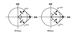
上述のように様々な構造のものがある中で、レゾルバから出力として得られる信号に注目すると、式(1)および式(2)で示すように、励磁信号を軸回転角θ(t)の余弦関数Cosθ(t)と正弦関数Sinθ(t)とで変調した信号を出力する1相励磁2相出力型のレゾルバが、最も一般的に用いられる。 Among the various structures as described above, when attention is paid to the signal obtained as an output from the resolver, the excitation signal is expressed by the shaft rotation angle θ (t) as shown by the equations (1) and (2). A one-phase excitation two-phase output type resolver that outputs a signal modulated by the cosine function Cosθ (t) and the sine function Sinθ (t) is most commonly used.
一方、信号処理の容易さから考えると、余弦関数同士の積Cosωot×Cosθ(t)、ならびに正弦関数同士の積Sinωot×Sinθ(t)を出力するレゾルバの方がよい。ところが、そのような信号を出力するレゾルバは、図30に示すような独立した回転子56、57と固定子58、59の対を2組用意して同軸上に構成する必要がある。このような方式は、2相励磁2相出力型と称されており、信号処理が非常に簡単になる。しかしながら、独立した回転子と固定子の対が2組必要で、機械的構造が複雑、かつ厚みの大きな構造となってしまうなど、構造上の不利益が大きいため、限定的にしか使われない。
On the other hand, considering the ease of signal processing, better resolver that outputs a cosine function between the product Cosω o t × Cosθ (t) , and the sine function between the product Sinω o t × Sinθ (t) . However, a resolver that outputs such a signal needs to have two pairs of
2相励磁2相出力型の信号処理が簡単になる理由について簡単に説明する。
2相励磁2相出力型のレゾルバより出力される信号VI、VQは次式で表される。
The reason why the signal processing of the two-phase excitation two-phase output type is simplified will be briefly described.
Signals V I and V Q output from a two-phase excitation two-phase output type resolver are expressed by the following equations.
上式から、その差と和を取ることにより、コサイン信号Cos(ωot+θ(t))およびCos(ωot−θ(t))が簡単に得られる。 By taking the difference and sum from the above equation, the cosine signals Cos (ω o t + θ (t)) and Cos (ω o t−θ (t)) can be easily obtained.
信号をこのように変換することができると、例えば、2つの信号のゼロクロス点の時間差を測定することによって非常に簡単に角度θ(t)を求めることができる。
図31はその信号処理を表すブロック図である。まず信号VIおよびVQの加減算により信号VPおよびVNを求める。次にコンパレータを通して信号VPおよびVNのゼロクロスを求める。そして、例えばその立ち上がりエッジを微分回路により算出し、信号VPとVNの立ち上がりエッジ間におけるクロックパルスの数をカウンタで計数すると、それは求める角度θ(t)に比例する。従って、このカウンタの計数値から角度θ(t)をデジタル変換した出力が取り出せる。
If the signal can be converted in this way, the angle θ (t) can be determined very simply, for example, by measuring the time difference between the zero cross points of the two signals.
FIG. 31 is a block diagram showing the signal processing. First the subtraction of the signals V I and V Q Request signal V P and V N. Then determine the zero-crossing the signals V P and V N through the comparator. Then, for example, the rising edge is calculated by the differential circuit and counts the number of clock pulses between the rising edge of the signal V P and V N in the counter, which is proportional to the angle theta (t) to be obtained. Therefore, an output obtained by digitally converting the angle θ (t) from the count value of the counter can be taken out.
次に、1相励磁2相出力型レゾルバに広く用いられている従来のR−D変換装置について説明する。図32にその構成の一例を示す。
例えば12ビットの角度データを得るために少なくとも11ビットの分解能、望ましくは12ビットの分解能を有するサイン信号およびコサイン信号のROM(Read only memory)が用意され、任意の角度φ(t)に対してサイン信号Sinφ(t)およびコサイン信号Cosφ(t)が生成される。これらは、D/A変換器(DAC)においてアナログ信号に変換される。求めるべき角度θ(t)に対して角度φ(t)を追従させるため、まずレゾルバより出力される信号VIにサイン信号Sinφ(t)が乗ぜられるとともに、信号VQにコサイン信号Cosφ(t)が乗ぜられる。そして、前者を反転して後者に加算することにより、次式に示す信号V1が生成される。
Next, a conventional RD converter widely used for a one-phase excitation two-phase output type resolver will be described. FIG. 32 shows an example of the configuration.
For example, in order to obtain 12-bit angle data, a ROM (Read only memory) of a sine signal and a cosine signal having at least 11-bit resolution, preferably 12-bit resolution is prepared, and for any angle φ (t) A sine signal Sinφ (t) and a cosine signal Cosφ (t) are generated. These are converted into analog signals in a D / A converter (DAC). Order to follow the angle θ (t), with respect to the angle phi (t) to be obtained, together with the sine signal sin [phi (t) is multiplied to the signal V I, which is first output from the resolver, the signal V Q cosine signal Cos (t ). Then, by inverting the former and adding it to the latter, a signal V1 shown in the following equation is generated.
更に式(7)の信号V1には、コサイン信号Cosωotが乗ぜられて同期検波が行われる。これにより、サイン信号Sin{θ(t)−φ(t)}の成分が取り出される。 Further, the signal V1 of the equation (7) is multiplied by the cosine signal Cosω o t to perform synchronous detection. Thereby, the component of the sine signal Sin {θ (t) −φ (t)} is extracted.
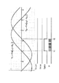
式(8)におけるコサインの項Cos2ωotは周波数が高いため、ループフィルタにおいて減衰し、式の末尾に示す低域の項のみが取り出される。このループフィルタの出力は、バイポーラ(両極性)VCO(電圧制御発振器:Voltage Controlled Oscillator)に入力される。バイポーラVCOでは、図33に示すように、入力信号の絶対値に比例する周波数を持ったパルス信号と、入力の極性を判定した極性信号が生成される。アップダウンカウンタでは、極性信号が正の場合、バイポーラVCOのパルス信号に応じてアップカウントがなされ、極性が負の場合にダウンカウントがなされる。その結果、アップダウンカウンタのカウンタ値は、角度φ(t)のデジタルデータそのものとなる。 Since the cosine term Cos2ω o t in equation (8) has a high frequency, it is attenuated by the loop filter, and only the low-frequency term shown at the end of the equation is extracted. The output of the loop filter is input to a bipolar (bipolar) VCO (Voltage Controlled Oscillator). In the bipolar VCO, as shown in FIG. 33, a pulse signal having a frequency proportional to the absolute value of the input signal and a polarity signal that determines the polarity of the input are generated. The up / down counter counts up according to the pulse signal of the bipolar VCO when the polarity signal is positive, and counts down when the polarity is negative. As a result, the counter value of the up / down counter is the digital data itself of the angle φ (t).
得られた角度φ(t)のデジタルデータは、サイン/コサインROMによってサイン信号Sinφ(t)およびコサイン信号Cosφ(t)のデジタルデータに変換され、これらがD/A変換器においてアナログ信号に変換される。ループフィルタは積分特性をしており、直流利得が無限大のため、出力が有限であるためには入力の定常値はゼロでなければならない。従って、角度φ(t)は角度θ(t)に追従するように変化する。 The obtained digital data of the angle φ (t) is converted into digital data of the sine signal Sinφ (t) and the cosine signal Cosφ (t) by the sine / cosine ROM, and these are converted into analog signals by the D / A converter. Is done. Since the loop filter has an integral characteristic and the direct current gain is infinite, the steady value of the input must be zero for the output to be finite. Accordingly, the angle φ (t) changes so as to follow the angle θ (t).
ところで、2相励磁2相出力型レゾルバの信号処理における図31に示すような信号のゼロクロス点を用いる角度の検出方法には、次のような不利益がある。 Incidentally, the angle detection method using the zero cross point of the signal as shown in FIG. 31 in the signal processing of the two-phase excitation two-phase output type resolver has the following disadvantages.
図34は、図31に示す回路における各部の信号波形の一例を示す図である。
図34の例において、信号VPがゼロクロスする時刻t1からクロックパルスCPのカウントが開始され、信号VNがゼロクロスする時刻t2でカウントが終了する。このカウンタ値は、角度θ(t)を反映しており、そのまま角度のデジタル値として使うことが可能である。カウント値は、時刻t2において1つ取り出される。
FIG. 34 is a diagram showing an example of signal waveforms at various parts in the circuit shown in FIG.
In the example of FIG. 34, counting from the time t1 to the signal V P to zero crossing of the clock pulse CP is started, counting is terminated at time t2 when the signal V N is the zero cross. This counter value reflects the angle θ (t) and can be used as it is as a digital value of the angle. One count value is taken out at time t2.
図31に示す回路では、角度θ(t)が非常に早く変化している場合、時刻t2で得られる角度のデジタル値が一体どの時点の角度を検出したデータであるか、厳密には定義できない。なぜなら、信号VPのゼロクロス点は時刻t1における信号VPの状態を示し、信号VNのゼロクロス点は時刻t2における信号VNの状態を示しているため、両者の位相差である角度θ(t)は、せいぜい時刻t1とt2のあたりにおける角度と定義するしかないからである。また、こうした角度のデータが時刻t2で出力されるということは、角度を検出してデータを得るまでに明らかに遅延が生じることを意味する。しかも、励磁周波数の1周期ごとに1つのデータしか得られないため、角度の連続的な変化を把握することができない。
こうした不利益があることから、ゼロクロス点によって角度を求めるR−D変換装置は、例えば高速で回転する軸の角度をリアルタイムで得るような応用には適さない。
In the circuit shown in FIG. 31, when the angle θ (t) is changing very quickly, it is not possible to precisely define at what point the detected angle is the digital value of the angle obtained at time t2. . Because the zero-cross point of the signal V P indicates the state of the signal V P at time t1, since the zero-cross point of the signal V N represents the state of the signal V N at time t2, the phase difference between the two angle theta ( This is because t) can only be defined as an angle around times t1 and t2. The fact that such angle data is output at time t2 means that there is a clear delay between the detection of the angle and the acquisition of the data. In addition, since only one data can be obtained for each period of the excitation frequency, it is impossible to grasp a continuous change in angle.
Because of these disadvantages, an RD converter that obtains an angle by a zero cross point is not suitable for an application that obtains an angle of a shaft that rotates at high speed in real time, for example.
加えて、信号のゼロクロス点を用いる方式の不利益として、外来ノイズに脆弱なことが挙げられる。ゼロクロス点の付近にわずかなノイズが混入すると、ゼロクロスの時間が揺らいでしまうからである。 In addition, a disadvantage of the method using the signal zero-cross point is that it is vulnerable to external noise. This is because if a little noise is mixed in the vicinity of the zero cross point, the time of the zero cross fluctuates.
一方、図32に示すR−D変換装置の特徴は、出力をリアルタイムで得ることである。アップダウンカウンタは角度φ(t)のデータを常に持ち続ける。角度φ(t)が角度θ(t)を追随するための遅延は存在するが、通常その遅延は角度θ(t)の機械的な動きに対して十分短いものである。また、この方式では波形全体を照合するため、一部に外来ノイズが重畳しても、ゼロクロス検出のように脆弱ではない。 On the other hand, the characteristic of the RD converter shown in FIG. 32 is that an output is obtained in real time. The up / down counter always keeps the data of the angle φ (t). Although there is a delay for the angle φ (t) to follow the angle θ (t), the delay is usually short enough for the mechanical movement of the angle θ (t). In addition, since the entire waveform is collated in this method, even if external noise is superimposed on a part, it is not as fragile as zero cross detection.
しかしながら、図32に示すR−D変換装置は、処理が複雑で回路規模が大きく、その結果消費電力が大きくコストが高いという不利益がある。
すなわち、複雑なバイポーラVCOやアップダウンカウンタを必要とする。また、12ビット分解能を得るためには最低11ビット、望ましくは12ビットの分解能と精度を持つ大容量のサイン/コサインROMと高分解能のD/A変換器を必要とする。
However, the RD converter shown in FIG. 32 has the disadvantage that the processing is complicated and the circuit scale is large, resulting in high power consumption and high cost.
That is, a complicated bipolar VCO and an up / down counter are required. In order to obtain 12-bit resolution, a large-capacity sine / cosine ROM having a resolution and accuracy of at least 11 bits, preferably 12 bits, and a high-resolution D / A converter are required.
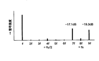
図35は、サイン/コサインROMとD/A変換器に必要な分解能を説明するための図である。角度2πを12ビットで分解するためには、正弦波の最大傾斜を考えると12ビットのπ分の1の分解能が必要である。すなわち、2πを212に分解すると、出力のステップの最大値は‘1/(212/π)’となる。従って10ビットでは少し足らず、11ビットが必要である。他の誤差要因を考えると余裕を見て12ビットが望ましい。これを単純にROMのテーブルで用意すると、かなり大きな容量のメモリが必要である。補間等によりメモリ容量を間引く手法も存在するが、いずれにしてもこの実現手段は高度で大規模なアナログ回路とデジタル回路の双方を必要とし、消費電力が大きく、高価なものとなる。 FIG. 35 is a diagram for explaining the resolution necessary for the sine / cosine ROM and the D / A converter. In order to resolve the angle 2π with 12 bits, a resolution of 1 / π of 12 bits is necessary considering the maximum slope of the sine wave. That is, when 2π is decomposed into 2 12 , the maximum value of the output step is “1 / (2 12 / π)”. Therefore, 10 bits is not enough, and 11 bits are required. Considering other error factors, 12 bits are desirable for a margin. If this is simply prepared as a ROM table, a considerably large amount of memory is required. There is a method of thinning out the memory capacity by interpolation or the like, but in any case, this realization means requires both an advanced and large-scale analog circuit and digital circuit, which consumes a large amount of power and is expensive.
バイポーラVCOは、周波数ゼロから発振しなければならないため、実現が難しい回路である。しかも、周波数ゼロ付近でデッドゾーンを生じ易くなり、位相ロックループの制御が不安定になる不利益がある。 Bipolar VCOs are difficult to implement because they must oscillate from zero frequency. In addition, there is a disadvantage that a dead zone is likely to occur near the frequency of zero and the control of the phase locked loop becomes unstable.
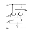
アナログ乗算回路もシステムの性能を制約する要素である。アナログ乗算回路は、ギルバート型乗算回路と呼ばれる図36に示す回路が汎用的に用いられる。この回路は、無線通信回路のミキサ(周波数混合回路)を筆頭に、広く用いられているアナログ機能回路である。非常にシンプルな回路で高周波まで動作できるように、バイポーラトランジスタの特性を巧みに利用している。しかしながら、例えば12ビットあるいはそれ以上の精度を必要とするR−D変換装置などの高精度な信号処理の機能回路としては、絶対精度が必要なレベルには及ばない。この回路の入力のダイナミックレンジは例えば20mVp−p程度であり、それに対する入力換算オフセット電圧は典型的には1〜2mV程度である。従って、絶対精度としては10%程度が保証範囲に過ぎない。エミッタ帰還抵抗等の手段でダイナミックレンジを拡大する方法もあるが、オフセット電圧も増えるため相対的な精度は大して改善されない。回路的な工夫にトリミング等の方法を併用しても1%の絶対精度を保証することは非常に困難である。従って、8ビット程度の精度は実現可能であるが、12ビットには遠く及ばない。
そのため、従来の高精度なR−D変換装置においては、ギルバート型乗算回路に替えて乗算型D/A変換器等を用いる等により乗算回路の精度の制約を回避する必要があった。従ってアナログ乗算回路の実現手段も、高精度を実現するためには消費電力の増大とコストの増加を招く要因となっていた。
An analog multiplication circuit is also an element that restricts system performance. As the analog multiplier circuit, a circuit shown in FIG. 36 called a Gilbert type multiplier circuit is generally used. This circuit is an analog functional circuit that is widely used, starting with a mixer (frequency mixing circuit) of a wireless communication circuit. The characteristic of the bipolar transistor is skillfully used so that it can operate to a high frequency with a very simple circuit. However, for example, a high-precision signal processing functional circuit such as an RD converter that requires an accuracy of 12 bits or more does not reach a level where absolute accuracy is required. The input dynamic range of this circuit is, for example, about 20 mVp-p, and the input conversion offset voltage is typically about 1 to 2 mV. Therefore, the absolute accuracy is only about 10% assured. Although there is a method of expanding the dynamic range by means such as an emitter feedback resistor, the relative accuracy is not greatly improved because the offset voltage increases. It is very difficult to guarantee an absolute accuracy of 1% even if a method such as trimming is used in combination with a circuit device. Therefore, an accuracy of about 8 bits can be realized, but is not far from 12 bits.
For this reason, in the conventional high-precision RD converter, it is necessary to avoid restrictions on the accuracy of the multiplication circuit by using a multiplication type D / A converter or the like instead of the Gilbert type multiplication circuit. Therefore, the means for realizing the analog multiplication circuit is also a factor that causes an increase in power consumption and cost in order to achieve high accuracy.
本発明はかかる事情に鑑みてなされたものであり、その目的は、簡易な構成でありながら、リアルタイムで精度の高い角度を求めることができる角度検出信号処理装置を提供することにある。 The present invention has been made in view of such circumstances, and an object of the present invention is to provide an angle detection signal processing apparatus capable of obtaining a highly accurate angle in real time with a simple configuration.
第1の発明は、第1の周波数を有する第1の励磁信号の振幅が第1の角度を有する余弦関数の信号によって変調された第1の角度検出信号と、上記第1の周波数を有する第2の励磁信号の振幅が上記第1の角度を有する正弦関数の信号によって変調された第2の角度検出信号とを含んだレゾルバの検出出力に基づいて、上記第1の角度の情報を取得する角度検出信号処理装置であって、信号処理部と、第1の位相ロック部と、第2の位相ロック部と、位相差演算部とを有する。
上記信号処理部は、上記第1の角度検出信号と上記第2の角度検出信号とに基づいて、上記第1の周波数を有するとともに上記第1の角度に応じた位相差を有する第1の信号および第2の信号を出力する。
上記第1の位相ロック部は、上記第1の信号に位相をロックさせた第1の位相ロック信号を生成し、当該第1の位相ロック信号の位相角を示す第1のデータを出力する。
上記第2の位相ロック部は、上記第2の信号に位相をロックさせた第2の位相ロック信号を生成し、当該第2の位相ロック信号の位相角を示す第2のデータを出力する。
上記位相差演算部は、上記第1のデータと上記第2のデータとに基づいて、上記第1の位相ロック信号と上記第2の位相ロック信号との位相差を演算する。
According to a first aspect of the present invention, a first angle detection signal in which the amplitude of a first excitation signal having a first frequency is modulated by a cosine function signal having a first angle, and a first angle detection signal having the first frequency. The information of the first angle is acquired based on the detection output of the resolver including the second angle detection signal in which the amplitude of the excitation signal of 2 is modulated by the sine function signal having the first angle. The angle detection signal processing device includes a signal processing unit, a first phase lock unit, a second phase lock unit, and a phase difference calculation unit.
The signal processing unit has a first signal having the first frequency and a phase difference corresponding to the first angle based on the first angle detection signal and the second angle detection signal. And a second signal is output.
The first phase lock unit generates a first phase lock signal whose phase is locked to the first signal, and outputs first data indicating a phase angle of the first phase lock signal.
The second phase lock unit generates a second phase lock signal whose phase is locked to the second signal, and outputs second data indicating a phase angle of the second phase lock signal.
The phase difference calculation unit calculates a phase difference between the first phase lock signal and the second phase lock signal based on the first data and the second data.
上記第1の発明の作用を説明する。
上記信号処理部において、上記第1の角度検出信号と上記第2の角度検出信号とに基づいて、上記第1の周波数を有するとともに上記第1の角度に応じた位相差を有する第1の信号および第2の信号が生成される。上記第1の位相ロック部では、上記第1の信号に位相をロックさせた第1の位相ロック信号が生成され、当該第1の位相ロック信号の位相角を示す第1のデータが出力される。上記第2の位相ロック部では、上記第2の信号に位相をロックさせた第2の位相ロック信号が生成され、当該第2の位相ロック信号の位相角を示す第2のデータが出力される。そして、上記位相差演算部において、上記第1のデータと上記第2のデータとに基づいて、上記第1の位相ロック信号と上記第2の位相ロック信号との位相差が演算される。
これにより、上記第1の信号および上記第2の信号の位相差は上記第1の角度に応じた値を持つ。また、これらの信号に位相ロックした上記第1の位相ロック信号および上記第2の位相ロック信号の位相差も、上記第1の信号および上記第2の信号の位相差に応じた値を持つ。従って、上記第1の位相ロック信号および上記第2の位相ロック信号の位相差は、上記第1の角度に応じた値を持つ。すなわち、上記位相差演算部の演算結果の位相差は、上記第1の角度に応じた値を持つ。
上記第1、第2の位相ロック部においては、何れも上記第1の周波数を有する信号に位相がロックされるため、仮に上記第1の角度が周波数ゼロの一定値になる場合でも、上記第1、第2の位相ロック信号は上記第1の周波数を持つように制御される。そのため、上記第1、第2の位相ロック信号の位相角を示す上記第1、第2のデータを出力するために、例えばバイポーラVCOのような周波数ゼロで発振する手段を設ける必要がない。
また、上記第1の信号と上記第2の信号との位相差を、ゼロクロス点の時間差により求めるのではなく、上記第1、第2の位相ロック部において刻々に出力される上記第1、第2のデータに基づいて求めるため、上記第1の角度の情報をリアルタイムで取得することが可能になる。また、ゼロクロス点を用いる方法に比べて、外来ノイズの影響を受け難くなる。
The operation of the first invention will be described.
In the signal processing unit, a first signal having the first frequency and a phase difference corresponding to the first angle based on the first angle detection signal and the second angle detection signal. And a second signal is generated. The first phase lock unit generates a first phase lock signal whose phase is locked to the first signal, and outputs first data indicating a phase angle of the first phase lock signal. . The second phase lock unit generates a second phase lock signal whose phase is locked to the second signal, and outputs second data indicating the phase angle of the second phase lock signal. . The phase difference calculation unit calculates a phase difference between the first phase lock signal and the second phase lock signal based on the first data and the second data.
Thereby, the phase difference between the first signal and the second signal has a value corresponding to the first angle. Further, the phase difference between the first phase lock signal and the second phase lock signal phase-locked to these signals also has a value corresponding to the phase difference between the first signal and the second signal. Therefore, the phase difference between the first phase lock signal and the second phase lock signal has a value corresponding to the first angle. That is, the phase difference of the calculation result of the phase difference calculation unit has a value corresponding to the first angle.
In the first and second phase lock units, since the phase is locked to the signal having the first frequency, even if the first angle is a constant value of zero frequency, the first The first and second phase lock signals are controlled to have the first frequency. Therefore, in order to output the first and second data indicating the phase angle of the first and second phase lock signals, there is no need to provide means for oscillating at a frequency of zero, such as a bipolar VCO.
In addition, the first and second phase lock units that are output momentarily do not calculate the phase difference between the first signal and the second signal based on the time difference between the zero cross points. Since it calculates | requires based on 2 data, it becomes possible to acquire the information of the said 1st angle in real time. In addition, it is less susceptible to external noise than the method using the zero cross point.
第2の発明は、上記第1の発明において、上記第1の励磁信号および上記第2の励磁信号が、上記第1の周波数を有する余弦関数の信号である場合に適用可能な発明である。
この場合、上記信号処理部は、上記第1の角度検出信号を実部成分、上記第2の角度検出信号を虚部成分とする複素信号を上記第1の信号として上記第1の位相ロック部に出力
するとともに、上記第1の角度検出信号を実部成分、上記第2の角度検出信号の極性を反転させた信号を虚部成分とする複素信号を上記第2の信号として上記第2の位相ロック部に出力する。
上記第1の位相ロック部および上記第2の位相ロック部は、位相角データ生成部と、複素信号処理部と、帰還部とを有する。
上記位相角データ生成部は、入力される帰還制御信号に応じた周期で反復されるデータであって、当該周期内の位相角を示すデータを、上記第1のデータもしくは上記第2のデータとして生成する。
上記複素信号処理部は、上記信号処理部から入力される第1の複素信号と、上記位相角データ生成部において生成されるデータに応じた位相角を有し互いに直交する第1信号成分および第2信号成分を含み、周波数が上記第1の複素信号の周波数に対して異なる極性に設定される第2の複素信号とを乗算した場合に得られる複素信号の偏角に応じた信号を生成する。
上記帰還部は、上記複素信号処理部において生成される信号に応じて、上記偏角が一定値に収束するように帰還制御を働かせる上記帰還制御信号を生成する。
The second invention is an invention applicable to the first invention when the first excitation signal and the second excitation signal are signals of a cosine function having the first frequency.
In this case, the signal processing unit uses the first angle detection signal as the first signal as a complex signal having the first angle detection signal as a real part component and the second angle detection signal as an imaginary part component. The second angle signal is a complex signal having a real part component as the first angle detection signal and an imaginary part component as a signal obtained by inverting the polarity of the second angle detection signal. Output to the phase lock unit.
The first phase lock unit and the second phase lock unit each include a phase angle data generation unit, a complex signal processing unit, and a feedback unit.
The phase angle data generation unit is data repeated in a cycle according to an input feedback control signal, and data indicating a phase angle in the cycle is used as the first data or the second data. Generate.
The complex signal processing unit includes a first complex signal input from the signal processing unit, a first signal component having a phase angle corresponding to data generated by the phase angle data generation unit, and orthogonal to each other. Generates a signal corresponding to the deviation angle of the complex signal obtained by multiplying the second complex signal including two signal components and having a frequency set to a different polarity with respect to the frequency of the first complex signal. .
The feedback unit generates the feedback control signal for performing feedback control so that the declination converges to a constant value according to the signal generated by the complex signal processing unit.
上記第2の発明の作用を説明する。
上記位相角データ生成部において生成されるデータは、上記帰還制御信号に応じた周期で反復されるデータであって、当該周期内の位相角を示すデータである。そのため、このデータに応じた位相角を有する上記第1信号成分および上記第2信号成分は、いずれも、上記帰還制御信号に応じた周波数を有する。すなわち、上記第2の複素信号は、上記帰還制御信号に応じた大きさの周波数を有するとともに該周波数が上記第1の複素信号の周波数に対して異なる極性に設定された複素信号である。
上記複素信号処理部においては、この第2の複素信号と上記第1の複素信号とを乗算した場合に得られる複素信号の偏角に応じた信号が生成される。
上記第2の複素信号と上記第1の複素信号とを乗算した場合に得られる複素信号の偏角は、上記第1の複素信号の偏角と上記第2の複素信号の偏角とを足し合わせた偏角に等しい。そのため、上記複素信号処理部においては、この足し合わせた偏角に応じた信号が生成される。
そして、上記帰還部では、上記複素信号処理部において生成された信号に応じて、上記足し合わせた偏角が一定値(例えばゼロ)に収束するように帰還制御を働かせる上記帰還制御信号が生成される。
偏角が一定になるということは、偏角が時間的に一定で、周波数がゼロになることに相当する。したがって、上記足し合わせた偏角が一定値に収束するためには、上記第1の複素信号および上記第2の複素信号が、互いに等しい大きさで極性が正負に反対の周波数を持っている必要がある。
そのため、上記第2の複素信号が負の周波数を持つ場合、この負の周波数が上記第1の複素信号の正の周波数を相殺するように、上記第2の複素信号の周波数が制御される。上記第2の複素信号が正の周波数を持つ場合は、この正の周波数が上記第1の複素信号の負の周波数を相殺するように、上記第2の複素信号の周波数が制御される。
これに対して、上記第2の複素信号と上記第1の複素信号とが同一極性の周波数を持っていると、上記足し合わされた偏角は常に周波数を持ち、これを一定値に収束させることができない。そのため、この場合、上記帰還制御が働かず、上記第2の複素信号の周波数は上記第1の複素信号の周波数に追従しない。
以上のことから、上記第1、第2の位相ロック部においてそれぞれ位相がロックされる上記第2の複素信号は、何れも、入力される上記第1の複素信号に含まれる特定の極性(上記第1の複素信号の周波数に対して異なる極性)の周波数成分に対して位相をロックさせた信号になる。
ところで、上記第1の位相ロック部に入力される上記第1の複素信号(上記第1の信号)は、上記第1の周波数を有する余弦関数の信号の振幅が上記第1の角度を有する余弦関数の信号によって変調された第1の角度検出信号を実部成分とし、上記第1の周波数を有する余弦関数の信号の振幅が上記第1の角度を有する正弦関数の信号によって変調された
第2の角度検出信号を虚部成分とする複素信号である。この複素信号は、上記第1の周波数を持ち、その符号が互いに異なる、正と負の周波数成分を有している。
また、上記第2の位相ロック部に入力される上記第1の複素信号(上記第2の信号)は、上記第1の角度検出信号を実部成分とし、上記第2の角度検出信号の極性反転信号を虚部成分とする複素信号である。この複素信号も、上記第1の周波数を持ち、その符号が互いに異なる、正と負の周波数成分を有している。
ただし、この上記第1の信号と上記第2の信号との間で同一極性の周波数を持つ信号成分同士を比較すると、正負何れの周波数についても、上記第1の角度に応じた位相差を有している。
そのため、このような上記第1、第2の信号に位相がロックされる上記第1、第2の位相ロック部の上記第2の複素信号も、同様に、上記第1の角度に応じた位相差を有している。
従って、これら2つの第2の複素信号の位相差を示す上記第1のデータおよび上記第2のデータに基づいて上記位相差演算部により演算される位相差は、上記第1の角度に応じた値を持つ。
The operation of the second invention will be described.
The data generated in the phase angle data generation unit is data that is repeated in a cycle corresponding to the feedback control signal, and is data that indicates a phase angle in the cycle. Therefore, both the first signal component and the second signal component having a phase angle corresponding to this data have a frequency corresponding to the feedback control signal. That is, the second complex signal is a complex signal having a frequency having a magnitude corresponding to the feedback control signal and having the frequency set to a different polarity with respect to the frequency of the first complex signal .
The complex signal processing unit generates a signal corresponding to the deviation angle of the complex signal obtained by multiplying the second complex signal and the first complex signal.
The deviation angle of the complex signal obtained by multiplying the second complex signal and the first complex signal is obtained by adding the deviation angle of the first complex signal and the deviation angle of the second complex signal. Equal to the combined declination. Therefore, in the complex signal processing unit, a signal corresponding to the added declination is generated.
The feedback unit generates the feedback control signal for performing feedback control so that the added declination converges to a constant value (for example, zero) according to the signal generated by the complex signal processing unit. The
A constant declination corresponds to a constant declination in time and zero frequency. Therefore, in order for the added declination to converge to a constant value, the first complex signal and the second complex signal need to have the same magnitude and opposite polarities in opposite polarity. There is.
Therefore, when the second complex signal has a negative frequency, the frequency of the second complex signal is controlled such that the negative frequency cancels the positive frequency of the first complex signal. When the second complex signal has a positive frequency, the frequency of the second complex signal is controlled such that the positive frequency cancels the negative frequency of the first complex signal.
On the other hand, if the second complex signal and the first complex signal have the same polarity frequency, the added declination always has a frequency and converges to a constant value. I can't. Therefore, in this case, the feedback control does not work, and the frequency of the second complex signal does not follow the frequency of the first complex signal.
From the above, the second complex signal whose phase is locked in each of the first and second phase lock units is both a specific polarity (the above-mentioned The signal is a signal whose phase is locked with respect to frequency components having different polarities with respect to the frequency of the first complex signal .
By the way, the first complex signal (the first signal) input to the first phase lock unit is a cosine in which the amplitude of a cosine function signal having the first frequency has the first angle. The first angle detection signal modulated by the function signal is a real component, and the amplitude of the cosine function signal having the first frequency is modulated by the sine function signal having the first angle. This is a complex signal having the imaginary part component of the angle detection signal. The complex signal has positive and negative frequency components having the first frequency and different signs.
Further, the first complex signal (the second signal) input to the second phase lock unit has the first angle detection signal as a real component, and the polarity of the second angle detection signal. It is a complex signal having an inverted signal as an imaginary part component. This complex signal also has positive and negative frequency components having the first frequency and different signs.
However, when signal components having the same polarity frequency are compared between the first signal and the second signal, there is a phase difference corresponding to the first angle for both positive and negative frequencies. is doing.
For this reason, the second complex signal of the first and second phase lock units whose phase is locked to the first and second signals is similarly changed according to the first angle. Has a phase difference.
Therefore, the phase difference calculated by the phase difference calculation unit based on the first data indicating the phase difference between the two second complex signals and the second data corresponds to the first angle. Has a value.
なお、上記位相角データ生成部は、入力される帰還制御信号に応じた周波数を有する信号を生成する信号生成部と、上記信号生成部において生成される信号を分周する所定ビット長のカウンタとを有しても良く、上記カウンタの計数値を上記第1のデータもしくは上記第2のデータとして出力しても良い。 The phase angle data generation unit includes a signal generation unit that generates a signal having a frequency corresponding to an input feedback control signal, and a counter having a predetermined bit length that divides the signal generated by the signal generation unit. The count value of the counter may be output as the first data or the second data.
また、上記複素信号処理部は、上記偏角に応じた信号として、上記第1の複素信号と上記第2の複素信号とを乗算した場合に得られる複素信号の実部成分または虚部成分に応じた信号を生成しても良く、上記帰還部は、上記複素演算部において生成される信号が一定値に収束するように帰還制御を働かせる上記帰還制御信号を生成しても良い。 Further, the complex signal processing unit applies a real component or an imaginary component of a complex signal obtained by multiplying the first complex signal and the second complex signal as a signal corresponding to the declination. A corresponding signal may be generated, and the feedback unit may generate the feedback control signal for performing feedback control so that the signal generated in the complex arithmetic unit converges to a constant value.
この場合、上記複素信号処理部は、複素信号生成部と、第1の演算部と、第2の演算部と、第2の演算部とを有しても良い。
上記複素信号生成部は、上記第1の演算部は、上記位相角データ生成部において生成されるデータに応じた位相角を有し互いに直交する上記第1信号成分および上記第2信号成分をそれぞれ生成する。
上記第1の演算部は、上記複素信号生成部において生成される上記第1信号成分と上記第1の複素信号の実部成分とを掛け合わせる。
上記第2の演算部は、上記複素信号生成部において生成される上記第2信号成分と上記第1の複素信号の虚部成分とを掛け合わせる。
上記第3の演算部は、上記第2の演算部および上記第2の演算部の演算結果の和もしくは差を演算する。
In this case, the complex signal processing unit may include a complex signal generation unit, a first calculation unit, a second calculation unit, and a second calculation unit.
In the complex signal generation unit, the first calculation unit has a phase angle corresponding to data generated in the phase angle data generation unit, and each of the first signal component and the second signal component orthogonal to each other. Generate.
The first arithmetic unit multiplies the first signal component generated by the complex signal generation unit and the real part component of the first complex signal.
The second calculation unit multiplies the second signal component generated by the complex signal generation unit and the imaginary part component of the first complex signal.
The third calculation unit calculates the sum or difference of the calculation results of the second calculation unit and the second calculation unit.
上記の構成によると、上記複素信号生成部において、上記位相角データ生成部において生成されるデータに応じた位相角を有し互いに直交する上記第1信号成分および上記第2信号成分がそれぞれ生成される。上記第1の演算部では、上記複素信号生成部において生成される上記第1信号成分と上記第1の複素信号の実部成分とが掛け合わされる。上記第2の演算部では、上記複素信号生成部において生成される上記第2信号成分と上記第1の複素信号の虚部成分とが掛け合わされる。そして、上記第3の演算部において、上記第1の演算部および上記第2の演算部の演算結果の和もしくは差が演算される。
この和もしくは差の演算結果は、上記第1の複素信号と上記第2の複素信号とを乗算した場合に得られる複素信号の実部または虚部に相当する信号になる。
According to the above configuration, the complex signal generator generates the first signal component and the second signal component that have a phase angle corresponding to the data generated by the phase angle data generator and are orthogonal to each other. The In the first arithmetic unit, the first signal component generated in the complex signal generation unit is multiplied by the real part component of the first complex signal. In the second calculation unit, the second signal component generated in the complex signal generation unit is multiplied by the imaginary part component of the first complex signal. Then, in the third calculation unit, the sum or difference of the calculation results of the first calculation unit and the second calculation unit is calculated.
The calculation result of the sum or difference is a signal corresponding to the real part or the imaginary part of the complex signal obtained by multiplying the first complex signal and the second complex signal.
あるいは、上記複素信号処理部は、第4の演算部と、第5の演算部と、第6の演算部とを有しても良い。
上記第4の演算部は、1周期を区分する複数の角度範囲の間で、上記位相角データ生成部のデータが示す位相角が別の角度範囲に移る場合、複数の重み係数の中から、当該移動先の角度範囲における所定の位相角での上記第1信号成分の瞬時値に応じた重み係数を選択して、上記第1の複素信号の実部成分に掛け合わせる。
上記第5の演算部は、1周期を区分する複数の角度範囲の間で、上記位相角データ生成部のデータが示す位相角が別の角度範囲に移る場合、複数の重み係数の中から、当該移動先の角度範囲における所定の位相角での上記第2信号成分の瞬時値に応じた重み係数を選択して、上記第1の複素信号の虚部成分に掛け合わせる。
上記第6の演算部は、上記第4の演算部および上記第5の演算部の演算結果の和もしくは差を演算する。
Alternatively, the complex signal processing unit may include a fourth calculation unit, a fifth calculation unit, and a sixth calculation unit.
When the phase angle indicated by the data of the phase angle data generation unit moves to another angle range between a plurality of angle ranges that divide one cycle, the fourth arithmetic unit is selected from a plurality of weighting factors, A weighting factor corresponding to the instantaneous value of the first signal component at a predetermined phase angle in the angular range of the movement destination is selected and multiplied by the real part component of the first complex signal.
When the phase angle indicated by the data of the phase angle data generation unit moves to another angle range between a plurality of angle ranges that divide one cycle, the fifth arithmetic unit is selected from a plurality of weighting factors, A weighting factor corresponding to the instantaneous value of the second signal component at a predetermined phase angle in the angular range of the movement destination is selected and multiplied by the imaginary part component of the first complex signal.
The sixth calculation unit calculates the sum or difference of the calculation results of the fourth calculation unit and the fifth calculation unit.
上記の構成によると、1周期を区分する複数の角度範囲の間で、上記位相角データ生成部のデータが示す位相角が別の角度範囲に移る場合に、複数の重み係数の中から、当該移動先の角度範囲における所定の位相角での上記第1信号成分の瞬時値に応じた重み係数が選択されて、上記第1の複素信号の実部成分に掛け合わされる。これにより、上記第1信号成分と上記第1の複素信号の実部成分との乗算結果が得られる。
上記第5の演算部では、1周期を区分する複数の角度範囲の間で、上記位相角データ生成部のデータが示す位相角が別の角度範囲に移る場合に、複数の重み係数の中から、当該移動先の角度範囲における所定の位相角での上記第2信号成分の瞬時値に応じた重み係数が選択されて、上記第1の複素信号の虚部成分に掛け合わされる。これにより、上記第2信号成分と上記第1の複素信号の虚部成分との乗算結果が得られる。
そして、上記第6の演算部において、上記第4の演算部および上記第5の演算部の乗算結果の和もしくは差が演算されると、その演算結果は、上記第1の複素信号と上記第2の複素信号とを乗算した場合に得られる複素信号の実部または虚部に相当する信号になる。
According to the above configuration, when the phase angle indicated by the data of the phase angle data generation unit moves to another angle range between a plurality of angle ranges dividing one cycle, A weighting factor corresponding to the instantaneous value of the first signal component at a predetermined phase angle in the angular range of the movement destination is selected and multiplied by the real part component of the first complex signal. Thereby, the multiplication result of the first signal component and the real part component of the first complex signal is obtained.
In the fifth calculation unit, when the phase angle indicated by the data of the phase angle data generation unit moves to another angle range between a plurality of angle ranges that divide one cycle, a plurality of weighting factors are selected. A weighting factor corresponding to the instantaneous value of the second signal component at a predetermined phase angle in the angle range of the destination is selected and multiplied by the imaginary part component of the first complex signal. As a result, a multiplication result of the second signal component and the imaginary part component of the first complex signal is obtained.
Then, when the sum or difference of the multiplication results of the fourth calculation unit and the fifth calculation unit is calculated in the sixth calculation unit, the calculation result is calculated as the first complex signal and the first calculation signal. A signal corresponding to a real part or an imaginary part of a complex signal obtained by multiplying two complex signals.
第3の発明は、上記第1の発明において、上記第1の励磁信号が上記第1の周波数を有する余弦関数の信号、上記第2の励磁信号が上記第1の周波数を有する正弦関数の信号である場合に適用可能な発明である。
この場合、上記信号処理部は、上記第1の角度検出信号と上記第2の角度検出信号との差を上記第1の信号として上記第1の位相ロック部に出力するとともに、上記第1の角度検出信号と上記第2の角度検出信号との和を上記第2の信号として上記第2の位相ロック部に出力する。
上記第1の位相ロック部および上記第2の位相ロック部は、位相角データ生成部と、位相検出部と、帰還部とを有する。
上記位相角データ生成部は、入力される帰還制御信号に応じた周期で反復されるデータであって、当該周期内の位相角を示すデータを、上記第1のデータもしくは上記第2のデータとして生成する。
上記位相検出部は、上記位相角データ生成部において生成されるデータに応じた位相角を有する位相ロック信号と、上記信号処理部からの入力信号との位相差を検出する。
上記帰還部は、上記位相検出部において検出される位相差が一定値に収束するように帰還制御を働かせる上記帰還制御信号を生成する。
In a third aspect based on the first aspect, the first excitation signal is a cosine function signal having the first frequency, and the second excitation signal is a sine function signal having the first frequency. This is an invention that can be applied.
In this case, the signal processing unit outputs the difference between the first angle detection signal and the second angle detection signal as the first signal to the first phase lock unit, and The sum of the angle detection signal and the second angle detection signal is output to the second phase lock unit as the second signal.
The first phase lock unit and the second phase lock unit each include a phase angle data generation unit, a phase detection unit, and a feedback unit.
The phase angle data generation unit is data repeated in a cycle according to an input feedback control signal, and data indicating a phase angle in the cycle is used as the first data or the second data. Generate.
The phase detection unit detects a phase difference between a phase lock signal having a phase angle corresponding to data generated by the phase angle data generation unit and an input signal from the signal processing unit.
The feedback unit generates the feedback control signal for performing feedback control so that the phase difference detected by the phase detection unit converges to a constant value.
上記第3の発明の作用を説明する。
上記第1の位相ロック部では、上記信号処理部から入力される上記第1の信号と上記第1の位相ロック信号との位相差が一定値に収束するように帰還制御が働く。また、上記第2の位相ロック部では、上記信号処理部から入力される上記第2の信号と上記第2の位相ロック信号との位相差が一定値に収束するように帰還制御が働く。そのため、上記位相差演算部において演算される上記第1の位相ロック信号と上記第2の位相ロック信号との位相差は、上記第1の信号と上記第2の信号との位相差に応じた値を持つ。
一方、上記第1の信号は、第1の周波数を有する余弦関数の信号の振幅が第1の角度を有する余弦関数の信号によって変調された第1の角度検出信号と、上記第1の周波数を有する正弦関数の信号の振幅が上記第1の角度を有する正弦関数の信号によって変調された第2の角度検出信号との差である。また、上記第2の信号は、この第1の角度検出信号と第2の角度検出信号との和である。そのため、上記第1の信号と上記第2の信号との間には、上記第1の角度に応じた位相差がある。
従って、上記位相差演算部において演算される上記位相差から、上記第1の角度の情報が取得される。
The operation of the third invention will be described.
The first phase lock unit performs feedback control so that the phase difference between the first signal input from the signal processing unit and the first phase lock signal converges to a constant value. Further, the second phase lock unit performs feedback control so that the phase difference between the second signal input from the signal processing unit and the second phase lock signal converges to a constant value. Therefore, the phase difference between the first phase lock signal and the second phase lock signal calculated in the phase difference calculation unit depends on the phase difference between the first signal and the second signal. Has a value.
On the other hand, the first signal includes a first angle detection signal obtained by modulating an amplitude of a cosine function signal having a first frequency with a cosine function signal having a first angle, and the first frequency. The amplitude of the sine function signal is a difference from the second angle detection signal modulated by the sine function signal having the first angle. The second signal is the sum of the first angle detection signal and the second angle detection signal. Therefore, there is a phase difference corresponding to the first angle between the first signal and the second signal.
Therefore, the information on the first angle is acquired from the phase difference calculated by the phase difference calculation unit.
なお、上記第3の発明において、上記位相角データ生成部は、入力される帰還制御信号に応じた周波数を有する信号を生成する信号生成部と、上記信号生成部において生成される信号を分周するカウンタとを有しても良く、上記カウンタの計数値を上記第1のデータもしくは上記第2のデータとして出力しても良い。 In the third aspect of the invention, the phase angle data generation unit generates a signal having a frequency corresponding to an input feedback control signal, and divides the signal generated by the signal generation unit. The counter value may be output as the first data or the second data.
また、上記位相検出部は、1周期を区分する複数の角度範囲の間で、上記位相角データ生成部のデータが示す位相角が別の角度範囲に移る場合、複数の重み係数の中から、当該移動先の角度範囲における所定の位相角での上記位相ロック信号の瞬時値に応じた重み係数を選択して、該選択した重み係数を上記信号処理部からの入力信号に掛け合わせても良い。
これにより、上記信号処理部からの入力信号と上記位相ロック信号との乗算結果が得られる。
In addition, when the phase angle indicated by the data of the phase angle data generation unit moves to another angle range between a plurality of angle ranges that divide one cycle, the phase detection unit, from among a plurality of weighting factors, A weighting factor corresponding to the instantaneous value of the phase lock signal at a predetermined phase angle in the angular range of the movement destination may be selected, and the selected weighting factor may be multiplied with the input signal from the signal processing unit. .
Thereby, the multiplication result of the input signal from the signal processing unit and the phase lock signal is obtained.
第4の発明は、第1の周波数を有する第1の励磁信号の振幅が第1の角度を有する余弦関数の信号によって変調された第1の角度検出信号と、上記第1の周波数を有する第2の励磁信号の振幅が上記第1の角度を有する正弦関数の信号によって変調された第2の角度検出信号とを含んだレゾルバの検出結果に基づいて、上記第1の角度の情報を取得する角度検出信号処理装置であって、第1の位相角データ生成部と、信号処理部と、位相ロック部と、位相差演算部とを有する。
上記第1の位相角データ生成部は、レゾルバに供給する上記第1の周波数を有する励磁信号の位相角を示す第1のデータを生成する。
上記信号処理部は、上記第1の角度検出信号と上記第2の角度検出信号とに基づいて、上記第1のデータが示す位相角に対して上記第1の角度に応じた位相差を有するとともに上記第1の周波数を有する信号を出力する。
上記位相ロック部は、上記信号処理部の出力信号に位相をロックさせた位相ロック信号を生成し、当該位相ロック信号の位相角を示す第2のデータを出力する。
上記位相差演算部は、上記第1のデータが示す位相角と上記第2のデータが示す位相角との差を演算する。
According to a fourth aspect of the present invention, there is provided a first angle detection signal in which the amplitude of the first excitation signal having the first frequency is modulated by a cosine function signal having the first angle, and the first angle detection signal having the first frequency. The information of the first angle is acquired based on the detection result of the resolver including the second angle detection signal in which the amplitude of the excitation signal of 2 is modulated by the sine function signal having the first angle. The angle detection signal processing device includes a first phase angle data generation unit, a signal processing unit, a phase lock unit, and a phase difference calculation unit.
The first phase angle data generation unit generates first data indicating a phase angle of an excitation signal having the first frequency supplied to the resolver.
The signal processing unit has a phase difference corresponding to the first angle with respect to the phase angle indicated by the first data based on the first angle detection signal and the second angle detection signal. In addition, a signal having the first frequency is output.
The phase lock unit generates a phase lock signal whose phase is locked to the output signal of the signal processing unit, and outputs second data indicating a phase angle of the phase lock signal.
The phase difference calculation unit calculates a difference between a phase angle indicated by the first data and a phase angle indicated by the second data.
上記第4の発明の作用を説明する。
上記第1の位相角データ生成部において、レゾルバに供給する励磁信号の位相角を示す第1のデータが生成される。上記信号処理部においては、上記第1の角度検出信号と上記第2の角度検出信号とに基づいて、上記第1のデータが示す位相角に対して上記第1の角度に応じた位相差を有するとともに上記第1の周波数を有する信号が出力される。上記位相ロック部では、上記信号処理部の出力信号に位相をロックさせた位相ロック信号が生成され、当該位相ロック信号の位相角を示す第2のデータが出力される。そして、上記位相差演算部において、上記第1のデータが示す位相角と上記第2のデータが示す位相角との差が演算される。
これにより、上記第1のデータが示す上記励磁信号の位相角と上記信号処理部より出力される信号の位相角との差は、上記第1の角度に応じた値を持つ。また、上記信号処理部の出力信号に位相ロックした上記位相ロック信号の位相角と上記信号処理部より出力される信号の位相角との差も、上記第1の角度に応じた値を持つ。従って、上記第1のデータが示す上記励磁信号の位相角と上記第2のデータが示す上記位相ロック信号の位相角との差は、上記第1の角度に応じた値を持つ。すなわち、上記位相差演算部の演算結果の位相差は、上記第1の角度に応じた値を持つ。
上記位相ロック部においては、上記第1の周波数を有する信号に位相がロックされるため、仮に上記第1の角度が周波数ゼロの一定値になる場合でも、上記位相ロック信号は上記第1の周波数を持つように制御される。そのため、上記位相ロック信号の位相角を示す上記第2のデータを出力するために、例えばバイポーラVCOのような周波数ゼロで発振する手段を設ける必要がない。
また、上記信号処理部の出力信号と上記励磁信号との位相差を、ゼロクロス点の時間差により求めるのではなく、上記第1の位相角データ生成部と上記位相ロック部とにおいて刻々に出力される上記第1、第2のデータに基づいて求めるため、上記第1の角度の情報をリアルタイムで取得することが可能になる。また、ゼロクロス点を用いる方法に比べて、外来ノイズの影響を受け難くなる。
The operation of the fourth invention will be described.
In the first phase angle data generation unit, first data indicating the phase angle of the excitation signal supplied to the resolver is generated. In the signal processing unit, based on the first angle detection signal and the second angle detection signal, a phase difference corresponding to the first angle with respect to the phase angle indicated by the first data is calculated. And a signal having the first frequency is output. The phase lock unit generates a phase lock signal whose phase is locked to the output signal of the signal processing unit, and outputs second data indicating the phase angle of the phase lock signal. The phase difference calculation unit calculates a difference between the phase angle indicated by the first data and the phase angle indicated by the second data.
Thereby, the difference between the phase angle of the excitation signal indicated by the first data and the phase angle of the signal output from the signal processing unit has a value corresponding to the first angle. Further, the difference between the phase angle of the phase lock signal phase-locked to the output signal of the signal processing unit and the phase angle of the signal output from the signal processing unit also has a value corresponding to the first angle. Therefore, the difference between the phase angle of the excitation signal indicated by the first data and the phase angle of the phase lock signal indicated by the second data has a value corresponding to the first angle. That is, the phase difference of the calculation result of the phase difference calculation unit has a value corresponding to the first angle.
In the phase lock unit, the phase is locked to the signal having the first frequency, so that even if the first angle is a constant value of zero frequency, the phase lock signal is the first frequency. Controlled to have. Therefore, in order to output the second data indicating the phase angle of the phase lock signal, there is no need to provide means for oscillating at a frequency of zero, such as a bipolar VCO.
Further, the phase difference between the output signal of the signal processing unit and the excitation signal is not obtained from the time difference of the zero cross point, but is output every moment in the first phase angle data generation unit and the phase lock unit. Since it calculates | requires based on the said 1st, 2nd data, it becomes possible to acquire the information of said 1st angle in real time. In addition, it is less susceptible to external noise than the method using the zero cross point.
第5の発明は、上記第4の発明において、上記第1の励磁信号および上記第2の励磁信号が、上記第1の周波数を有する余弦関数の信号である場合に適用可能な発明である。
上記信号処理部は、上記第1の角度検出信号を実部成分、上記第2の角度検出信号を虚部成分とする複素信号を出力する。
上記位相ロック部は、第2の位相角データ生成部と、複素信号処理部と、帰還部とを有する。
上記第2の位相角データ生成部は、入力される帰還制御信号に応じた周期で反復されるデータであって、当該周期内の位相角を示すデータを上記第2のデータとして生成する。
上記複素信号処理部は、上記信号処理部から入力される第1の複素信号と、上記第2の位相角データ生成部において生成される上記第2のデータに応じた位相角を有し互いに直交する第1信号成分および第2信号成分を含み、周波数が上記第1の複素信号の周波数に対して異なる極性に設定される第2の複素信号と、を乗算した場合に得られる複素信号の偏角に応じた信号を生成する。
上記帰還部は、上記複素信号処理部において生成される信号に応じて、上記偏角が一定値に収束するように帰還制御を働かせる上記帰還制御信号を生成する。
The fifth invention is an invention applicable to the fourth invention when the first excitation signal and the second excitation signal are signals of a cosine function having the first frequency.
The signal processing unit outputs a complex signal having the first angle detection signal as a real part component and the second angle detection signal as an imaginary part component.
The phase lock unit includes a second phase angle data generation unit, a complex signal processing unit, and a feedback unit.
The second phase angle data generation unit generates data indicating the phase angle within the cycle as the second data, which is repeated in a cycle according to the input feedback control signal.
The complex signal processing unit has a phase angle corresponding to the first complex signal input from the signal processing unit and the second data generated by the second phase angle data generation unit, and is orthogonal to each other Of the complex signal obtained by multiplying the second complex signal, which includes the first signal component and the second signal component, and the frequency is set to a different polarity with respect to the frequency of the first complex signal. A signal corresponding to the corner is generated.
The feedback unit generates the feedback control signal for performing feedback control so that the declination converges to a constant value according to the signal generated by the complex signal processing unit.
上記第5の発明の作用を説明する。
上記位相ロック部の上記第2の複素信号は、先に説明した上記第2の発明における上記第1、第2の位相ロック部と同様に、入力される上記第1の複素信号に含まれる特定の極性(上記所定の極性と反対の極性)の周波数を持つ成分に対して位相をロックさせた信号になる。
一方、上記第1の複素信号は、上記第1の周波数を有する余弦関数の信号の振幅が上記第1の角度を有する余弦関数の信号によって変調された第1の角度検出信号を実部成分とし、上記第1の周波数を有する余弦関数の信号の振幅が上記第1の角度を有する正弦関数の信号によって変調された第2の角度検出信号を虚部成分とする、複素信号である。この複素信号は、上記第1の周波数を持っており、その正の極性を持つ周波数成分が、上記励磁信号に対して上記第1の角度に応じた位相差を有している。また、負の極性を持つ周波数成分も、上記励磁信号に対して上記第1の角度に応じた位相差を有している。
そのため、上記第1の複素信号における一方の極性の周波数成分に対して位相をロックさせた上記第2の複素信号は、上記励磁信号に対して上記第1の角度に応じた位相差を有している。
従って、第1のデータが示す上記励磁信号の位相角と、上記第2のデータが示す上記第2の複素信号の位相角との差を上記位相差演算部において演算することにより、その演算結果から、上記第1の角度の情報を取得することが可能になる。
The operation of the fifth invention will be described.
The second complex signal of the phase lock unit is specified in the input first complex signal as in the first and second phase lock units of the second invention described above. This is a signal whose phase is locked with respect to a component having a frequency of a negative polarity (a polarity opposite to the predetermined polarity).
On the other hand, the first complex signal has, as a real part component, a first angle detection signal in which the amplitude of the cosine function signal having the first frequency is modulated by the cosine function signal having the first angle. , A complex signal in which the second angle detection signal obtained by modulating the amplitude of the cosine function signal having the first frequency by the sine function signal having the first angle is an imaginary part component. The complex signal has the first frequency, and the frequency component having the positive polarity has a phase difference corresponding to the first angle with respect to the excitation signal. The frequency component having a negative polarity also has a phase difference corresponding to the first angle with respect to the excitation signal.
Therefore, the second complex signal whose phase is locked with respect to the frequency component of one polarity in the first complex signal has a phase difference corresponding to the first angle with respect to the excitation signal. ing.
Therefore, by calculating the difference between the phase angle of the excitation signal indicated by the first data and the phase angle of the second complex signal indicated by the second data in the phase difference calculation unit, the calculation result is obtained. From this, it is possible to acquire information on the first angle.
第6の発明は、上記第4の発明において、上記第1の励磁信号が上記第1の周波数を有する余弦関数の信号、上記第2の励磁信号が上記第1の周波数を有する正弦関数の信号である場合に適用可能な発明である。
上記信号処理部は、上記第1の角度検出信号と上記第2の角度検出信号との和もしくは差を上記位相ロック部に出力する。
上記位相ロック部は、第2の位相角データ生成部と、位相検出部と、帰還部とを有する。
上記第2の位相角データ生成部は、入力される帰還制御信号に応じた周期で反復されるデータであって、当該周期内の位相角を示すデータを上記第2のデータとして生成する。
上記位相検出部は、上記第2の位相角データ生成部において生成される上記第2のデータに応じた位相角を有する位相ロック信号と、上記信号処理部からの入力信号との位相差を検出する。
上記帰還部は、上記位相差検出部において検出される位相差が一定値に収束するように帰還制御を働かせる上記帰還制御信号を生成する。
In a sixth aspect based on the fourth aspect, the first excitation signal is a cosine function signal having the first frequency, and the second excitation signal is a sine function signal having the first frequency. This is an invention that can be applied.
The signal processing unit outputs a sum or difference between the first angle detection signal and the second angle detection signal to the phase lock unit.
The phase lock unit includes a second phase angle data generation unit, a phase detection unit, and a feedback unit.
The second phase angle data generation unit generates data indicating the phase angle within the cycle as the second data, which is repeated in a cycle according to the input feedback control signal.
The phase detection unit detects a phase difference between a phase lock signal having a phase angle corresponding to the second data generated in the second phase angle data generation unit and an input signal from the signal processing unit. To do.
The feedback unit generates the feedback control signal for performing feedback control so that the phase difference detected by the phase difference detection unit converges to a constant value.
上記第6の発明の作用を説明する。
上記位相ロック部では、上記信号処理部からの入力信号と上記位相ロック信号との位相差が一定値に収束するように帰還制御が働く。また、上記位相ロック信号は、上記第2の位相角データ生成部において生成される上記第2のデータに応じた位相角を有する。そのため、上記第2のデータは、上記信号処理部からの入力信号の位相角に応じたデータとなる。
一方、上記信号処理部の出力信号は、第1の周波数を有する余弦関数の信号の振幅が第1の角度を有する余弦関数の信号によって変調された第1の角度検出信号と、上記第1の周波数を有する正弦関数の信号の振幅が上記第1の角度を有する正弦関数の信号によって変調された第2の角度検出信号との和もしくは差である。この和の信号および差の信号は、何れも、上記励磁信号(第1の励磁信号、第2の励磁信号)との間に上記第1の角度に応じた位相差を有する。
そのため、上記第1のデータが示す上記励磁信号の位相角と上記第2のデータが示す上記信号処理部の出力信号の位相角との間には、上記第1の角度に応じた位相差がある。
従って、上記位相差演算部において演算される上記位相差から、上記第1の角度の情報が取得される。
The operation of the sixth invention will be described.
In the phase lock unit, feedback control works so that the phase difference between the input signal from the signal processing unit and the phase lock signal converges to a constant value. The phase lock signal has a phase angle corresponding to the second data generated in the second phase angle data generation unit. Therefore, the second data is data according to the phase angle of the input signal from the signal processing unit.
Meanwhile, the output signal of the signal processing unit includes a first angle detection signal in which the amplitude of a cosine function signal having a first frequency is modulated by a cosine function signal having a first angle, and the first angle detection signal. The amplitude of a sine function signal having a frequency is the sum or difference from the second angle detection signal modulated by the sine function signal having the first angle. Both the sum signal and the difference signal have a phase difference corresponding to the first angle with the excitation signal (first excitation signal, second excitation signal).
Therefore, there is a phase difference according to the first angle between the phase angle of the excitation signal indicated by the first data and the phase angle of the output signal of the signal processing unit indicated by the second data. is there.
Therefore, the information on the first angle is acquired from the phase difference calculated by the phase difference calculation unit.
本発明によれば、バイポーラVCO等を含まない簡易な構成でありながら、リアルタイムで精度の高い角度を求めることができる。 According to the present invention, a highly accurate angle can be obtained in real time while having a simple configuration that does not include a bipolar VCO or the like.
以下、本発明を実施するための5つの形態について、図面を参照しながら説明する。 Hereinafter, five modes for carrying out the present invention will be described with reference to the drawings.
<第1の実施形態>
図1は、本発明の第1の実施形態に係る角度検出信号処理装置の構成の一例を示す図である。
第1の実施形態に係る角度検出信号処理装置は、1相励磁2相出力型のレゾルバから出力される式(1)および式(2)に示す角度検出信号
VI=Cosωot・Cosθ(t);
VQ=Cosωot・Sinθ(t);
を入力し、角度θ(t)の情報を取得するものである。なお、以下の説明では、角度検出信号の振幅Voを‘1’として表記を省略する。
<First Embodiment>
FIG. 1 is a diagram illustrating an example of a configuration of an angle detection signal processing device according to the first embodiment of the present invention.
The angle detection signal processing apparatus according to the first embodiment includes an angle detection signal V I = Cosω o t · Cosθ (shown in equations (1) and (2)) output from a one-phase excitation two-phase output type resolver. t);
V Q = Cosω o t · Sinθ (t);
To obtain information on the angle θ (t). In the following description, it is omitted expressed as the amplitude V o of the angle detection signal '1'.
図1に示す角度検出信号処理装置は、信号処理部400と、第1の位相ロック部PLL1と、第2の位相ロック部PLL2と、位相差演算部500とを有する。
信号処理部400は、本発明の信号処理部の一実施形態である。
第1の位相ロック部PLL1は、本発明の第1の位相ロック部の一実施形態である。
第2の位相ロック部PLL2は、本発明の第2の位相ロック部の一実施形態である。
位相差演算部500は、本発明の位相差演算部の一実施形態である。
The angle detection signal processing apparatus shown in FIG. 1 includes a
The
The first phase lock unit PLL1 is an embodiment of the first phase lock unit of the present invention.
The second phase lock unit PLL2 is an embodiment of the second phase lock unit of the present invention.
The phase
[信号処理部400]
信号処理部400は、角度検出信号VIおよびVQとに基づいて、周波数ωoを有するとともに角度θ(t)に応じた位相差を有する複素信号_VCPおよび_VCNを出力する。なお、本明細書では、複素信号の記号に下線‘_’を付すことによって複素信号と実信号とを区別する。
[Signal Processing Unit 400]
Based on the angle detection signals V I and V Q , the
信号処理部400は、例えば図1に示すように、角度検出信号VIを実部成分、角度検出信号VQを虚部成分とする複素信号_VCPと、角度検出信号VIを実部成分、角度検出信号VQの極性を反転した信号を虚部成分とする複素信号_VCNとを出力する。
後で詳しく述べるように、複素信号_VCPおよび_VCNは、正の周波数(ωo)の成分と負の周波数(−ωo)の成分をそれぞれ有しており、互いに同一極性の周波数成分同士を比較すると、その位相差は角度2×θ(t)になっている。
The
As will be described in detail later, each of the complex signals _V CP and _V CN has a positive frequency component (ω o ) and a negative frequency component (−ω o ). Are compared, the phase difference is an
信号処理部400に含まれる極性反転回路401は、角度検出信号VQの極性を反転する回路である。
The
[PLL1,PLL2]
位相ロック部PLL1は、複素信号_VCPに位相をロックさせた複素信号_VUOを生成し、この複素信号_VUOの位相角に応じたデータPA1を出力する。
位相ロック部PLL2は、複素信号_VCNに位相をロックさせた複素信号_VLOを生成し、この複素信号_VLOの位相角に応じたデータPA2を出力する。
[PLL1, PLL2]
The phase lock unit PLL1 generates a complex signal _V UO whose phase is locked to the complex signal _V CP , and outputs data PA1 corresponding to the phase angle of the complex signal _V UO .
The phase lock unit PLL2 generates a complex signal _V LO whose phase is locked to the complex signal _V CN and outputs data PA2 corresponding to the phase angle of the complex signal _V LO .
通常の位相ロック回路が実信号の位相にロックするものであるのに対し、位相ロック部PLL1およびPLL2は、入力される複素信号に含まれる特定の極性を持つ周波数成分の位相にロックする。すなわち、入力される複素信号が正と負の周波数成分を有する場合に、例えば正の周波数成分に位相をロックさせた複素信号_VUO、_VLOを生成する。そして、生成した複素信号の位相角のデータPA1、PA2をそれぞれ出力する。 While the normal phase lock circuit locks to the phase of the actual signal, the phase lock units PLL1 and PLL2 lock to the phase of the frequency component having a specific polarity included in the input complex signal. That is, when the input complex signal has positive and negative frequency components, for example, complex signals _V UO and _V LO in which the phase is locked to the positive frequency component are generated. Then, phase angle data PA1 and PA2 of the generated complex signal are output.
位相ロック部PLL1およびPLL2の詳細な構成について説明する。 A detailed configuration of the phase lock units PLL1 and PLL2 will be described.
図1の例において、位相ロック部PLL1は、位相角データ生成部300−1と、複素信号処理部100−1と、帰還部200−1とを有する。
また、位相ロック部PLL2は、位相角データ生成部300−2と、複素信号処理部100−2と、帰還部200−2とを有する。
位相角データ生成部300−1,300−2は、本発明の位相角データ生成部の一実施形態である。
複素信号処理部100−1,100−2は、本発明の複素信号処理部の一実施形態である。
帰還部200−1,200−2は、本発明の帰還部の一実施形態である。
In the example of FIG. 1, the phase lock unit PLL1 includes a phase angle data generation unit 300-1, a complex signal processing unit 100-1, and a feedback unit 200-1.
Further, the phase lock unit PLL2 includes a phase angle data generation unit 300-2, a complex signal processing unit 100-2, and a feedback unit 200-2.
The phase angle data generation units 300-1 and 300-2 are an embodiment of the phase angle data generation unit of the present invention.
The complex signal processing units 100-1 and 100-2 are an embodiment of the complex signal processing unit of the present invention.
The feedback units 200-1 and 200-2 are an embodiment of the feedback unit of the present invention.
位相角データ生成部300−1は、帰還部200−1より入力される帰還制御信号Vf1に応じた周期で反復されるデータであって、当該周期内の位相角を示すデータを、上述した位相角のデータPA1として生成する。 The phase angle data generation unit 300-1 is data that is repeated in a cycle according to the feedback control signal Vf1 input from the feedback unit 200-1, and the phase angle data in the cycle is converted to the phase described above. It is generated as corner data PA1.
位相角データ生成部300−1は、例えば、信号生成部301とカウンタ302とを有する。
信号生成部301は、本発明の信号生成部の一実施形態である。
カウンタ302は、本発明のカウンタの一実施形態である。
The phase angle data generation unit 300-1 includes, for example, a
The
The
信号生成部301は、帰還制御信号Vf1に応じた周波数を有する信号を生成する回路であり、例えば電圧制御発振器(VCO)などを用いて構成される。
The
カウンタ302は、信号生成部301において生成される信号を分周する回路であり、所定ビット長nの計数値を出力する。例えば、‘0’から‘2n−1’まで1ずつ増える計数値を反復して出力する。カウンタ302は、このカウンタ302の計数値を先に述べた位相角のデータPA1として出力する。
The
位相角データ生成部300−2は、帰還部200−2より入力される帰還制御信号Vf2に応じた周期で反復されるデータであって、当該周期内の位相角を示すデータを、上述した位相角のデータPA2として生成する。
位相角データ生成部300−2も、例えば上述した信号生成部301とカウンタ302とを用いて構成されており、カウンタ302の計数値を位相角のデータPA2として出力する。
The phase angle data generation unit 300-2 is data that is repeated in a cycle according to the feedback control signal Vf2 input from the feedback unit 200-2, and represents the phase angle in the cycle as the above-described phase. It is generated as corner data PA2.
The phase angle data generation unit 300-2 is also configured by using, for example, the
複素信号処理部100−1は、信号処理部400から入力される複素信号_VCPと、位相角データ生成部300−1において生成されるデータPA1に応じた位相角(ωot+φ(t))を有し互いに直交する信号成分VUO−IおよびVUO−Qを含み、周波数が所定の極性(例えば負)に設定される複素信号_VUOと、を乗算した場合に得られる複素信号の偏角に応じた信号VUCを生成する。この偏角に応じた信号VUCとして、例えば、複素信号_VCPと複素信号_VUOとを複素乗算した場合に得られる複素信号の実部成分または虚部成分に応じた信号を生成する。
The complex signal processing unit 100-1 has a phase angle (ω o t + φ (t)) corresponding to the complex signal _V CP input from the
複素信号処理部100−1は、例えば、乗算部101および102と、加算部
103と、複素信号生成部107とを有する。
乗算部101は、本発明の第1の演算部の一実施形態である。
乗算部102は、本発明の第2の演算部の一実施形態である。
加算部103は、本発明の第3の演算部の一実施形態である。
複素信号生成部107は、本発明の複素信号生成部の一実施形態である。
The complex signal processing unit 100-1 includes, for example,
The
The adding
The complex
複素信号生成部107は、位相角データ生成部300−1において生成されるデータPA1に応じた位相角を有し互いに直交する信号成分VUO−IおよびVUO−Qをそれぞれ生成する。信号成分VUO−Iを実部成分、信号成分VUO−Qを虚部成分とする複素信号の周波数は、所定の極性(例えば負)を持つように設定される。
The complex
複素信号生成部107は、例えば、サイン/コサインの振幅データをテーブルとして持つROMを用いて位相角のデータを振幅のデータに変換し、それをD/A変換器によってアナログの信号に変換することにより、信号成分VUO−IおよびVUO−Qを生成しても良い。
The complex
また、複素信号生成部107は、図2に示すような簡易的な回路を用いて、位相が4分の1周期ずれている矩形状の信号成分VUO−IおよびVUO−Qを生成しても良い。
図2は、複素信号生成部107の構成の一例を示す図である。複素信号生成部107は、例えば図2(A)に示すように、排他的論理和回路XORと、アンプA1およびA2を用いて構成することができる。
排他的論理和回路XORは、カウンタ302の計数値の最上位ビットbMSBとその下位ビットbMSB−1との排他的論理和を演算する。
アンプA1は、ビットbMSBが‘1’の場合に正、‘0’の場合に負の極性を持つ正負が同一振幅の矩形状の信号を、信号成分VUO−Qとして出力する。
アンプA2は、ビットbMSB−1が‘1’の場合に正、‘0’の場合に負の極性を持つ正負が同一振幅の信号VUO−Iを出力する。
このような回路によれば、図2(B)に示す論理値のパターンからも分かるように、位相が4分の1周期ずれている矩形信号を生成することができる。
Further, the complex
FIG. 2 is a diagram illustrating an example of the configuration of the complex
The exclusive OR circuit XOR calculates the exclusive OR of the most significant bit b MSB of the count value of the
The amplifier A1 outputs, as the signal component V UO-Q , a rectangular signal having positive and negative amplitudes with the same polarity when the bit b MSB is “1” and when it is “0”.
The amplifier A2 outputs a signal V UO-I having a positive polarity when the bit b MSB-1 is “1” and a negative polarity when the bit b MSB-1 is “0” and the same amplitude.
According to such a circuit, as can be seen from the logical value pattern shown in FIG. 2B, it is possible to generate a rectangular signal whose phase is shifted by a quarter period.
このような矩形信号を用いると、乗算結果に高調波成分が含まれるが、後で詳しく説明するように、角度θ(t)が比較的ゆっくり変化する場合や位相ロック部の帯域が狭い場合などでは、この高調波成分を帰還部200−1によって十分に減衰させることができるため、必要十分な精度を得ることができる。 When such a rectangular signal is used, a harmonic component is included in the multiplication result. As will be described in detail later, when the angle θ (t) changes relatively slowly, or when the band of the phase lock unit is narrow, etc. Then, since this harmonic component can be sufficiently attenuated by the feedback unit 200-1, necessary and sufficient accuracy can be obtained.
なお、図2(A)に示す回路は、後の実施形態で説明する擬似正弦波を用いた乗算に対応させると、図2(C)に示すように、最も簡単な2値の擬似正弦波乗算を行っていることに対応する。
図2(C)の例においては、乗算部101および102にそれぞれスイッチ回路111および極性反転回路112が設けられる。
乗算部101のスイッチ回路111は、ビットbMSB−1が‘1’の場合に角度検出信号VIをそのまま出力し、‘0’の場合には角度検出信号VIを極性反転回路112で極性反転して出力する。
乗算部102のスイッチ回路111は、排他的論理和回路XORの出力が‘1’の場合に角度検出信号VQ(もしくは−VQ)をそのまま出力し、‘0’の場合には角度検出信号VI(もしくは−VQ)を極性反転回路112で極性反転して出力する。
Note that the circuit shown in FIG. 2A is the simplest binary pseudo sine wave as shown in FIG. 2C when it is adapted to the multiplication using the pseudo sine wave described in the following embodiment. This corresponds to performing multiplication.
In the example of FIG. 2C, the switching
The
The
乗算部101は、複素信号生成部107において生成される信号成分VUO−Qと、複素信号_VCPの実部成分である角度検出信号VIとを掛け合わせる。乗算部101は、例えばギルバート型乗算回路などのアナログ乗算器を用いて構成しても良いし、乗算型のD/A変換器を用いても良い。あるいは、図2(C)に示すように、スイッチ回路と極性判定回路を用いて極性を切り替えて出力する構成でも良い。
The
乗算部102は、複素信号生成部107において生成される信号成分VUO−Iと、複素信号_VCPの虚部成分である角度検出信号VQとを掛け合わせる。乗算部102についても、乗算部101と同様、アナログ乗算器や乗算型D/A変換器で構成しても良いし、図2(C)に示すようにスイッチ回路と極性判定回路を用いて構成しても良い。
The
加算部103は、乗算部101および102の乗算結果の和を上述した信号VUCとして出力する。加算部103より出力される信号VUCは、複素信号_VCPと_VUOとを複素乗算した場合に得られる複素信号の虚部成分に相当する信号になる。
なお、複素乗算結果の実部成分を出力する場合などにおいては、乗算部101および102の乗算結果の差を演算して出力する構成としても良い。
In the case of outputting the real part component of the complex multiplication result, the difference between the multiplication results of the
複素信号処理部100−2は、信号処理部400から入力される複素信号_VCNと、位相角データ生成部300−2において生成されるデータPA2に応じた位相角(ωot−φ(t))を有し互いに直交する信号成分VLO−IおよびVLO−Qを含み、周波数が所定の極性(例えば負)に設定される複素信号_VLOと、を乗算した場合に得られる複素信号の偏角に応じた信号VLCを生成する。この偏角に応じた信号VLCとしては、例えば、複素信号_VCNと_VLOとを複素乗算した場合に得られる複素信号の実部成分または虚部成分に応じた信号を生成する。
複素信号処理部100−2は、例えば上述と同様な乗算部101および102と、加算部103と、複素信号生成部107とを用いて構成しても良い。この場合、複素信号_VCNと_VLOとを複素乗算した場合に得られる複素信号の虚部成分に相当する信号VLCを生成する。
The complex signal processing unit 100-2 receives the phase angle (ω o t−φ (t) corresponding to the complex signal _V CN input from the
The complex signal processing unit 100-2 may be configured using, for example,
帰還部200−1は、複素信号処理部100−1において生成される信号VUCに応じて、複素信号_VCPおよび_VUOの乗算結果として得られる複素信号の偏角が一定値に収束するように帰還制御を働かせる帰還制御信号Vf1を生成する。 The feedback unit 200-1 is configured so that the deviation angle of the complex signal obtained as a result of multiplication of the complex signals _V CP and _V UO converges to a constant value according to the signal V UC generated by the complex signal processing unit 100-1. A feedback control signal Vf1 for causing feedback control to operate is generated.
帰還部200−1は、例えば、複素信号処理部100−1において生成される信号VUCを所定の伝達特性をもって増幅するフィルタ回路として構成される。 The feedback unit 200-1 is configured, for example, as a filter circuit that amplifies the signal V UC generated in the complex signal processing unit 100-1 with a predetermined transfer characteristic.
図3(A)は、帰還部200−1の構成の一例を示す図であり、図3(B)はその伝達特性の一例を示す図である。
図3(A)に示す帰還部200−1は、演算増幅器OP1と、抵抗R1およびR2と、キャパシタC1およびC2を有する。
演算増幅器OP1の負側入力端子(−)と出力との間には、抵抗R2およびキャパシタC2の直列回路とキャパシタC1とが並列に接続されており、正側入力端子(+)はグランドに接続される。帰還部200−1の入力信号は、抵抗R1を介して演算増幅器OP1の負側入力端子(−)へ入力さる。帰還部200−1の出力信号は、演算増幅器OP1の出力端子から出力される。
このような構成によると、図3(B)の伝達特性に示すように、周波数が低くなるほど帰還部200−1のゲインは大きくなり、直流では演算増幅器OP1の開ループゲインに応じた非常に大きなゲインとなる。
FIG. 3A is a diagram illustrating an example of the configuration of the feedback unit 200-1, and FIG. 3B is a diagram illustrating an example of the transfer characteristic thereof.
The feedback unit 200-1 illustrated in FIG. 3A includes an operational amplifier OP1, resistors R1 and R2, and capacitors C1 and C2.
Between the negative input terminal (−) of the operational amplifier OP1 and the output, a series circuit of a resistor R2 and a capacitor C2 and the capacitor C1 are connected in parallel, and the positive input terminal (+) is connected to the ground. Is done. The input signal of the feedback unit 200-1 is input to the negative side input terminal (−) of the operational amplifier OP1 through the resistor R1. The output signal of the feedback unit 200-1 is output from the output terminal of the operational amplifier OP1.
According to such a configuration, as shown in the transfer characteristic of FIG. 3B, the gain of the feedback unit 200-1 increases as the frequency decreases, and the direct current is very large according to the open loop gain of the operational amplifier OP1. Gain.
このように、帰還部200−1の直流利得が非常に大きくなる場合、複素信号処理部100−1の出力信号VUCは定常状態においてゼロになる必要がある。この場合、出力信号VUCがゼロの状態において、複素信号_VUOの位相が複素信号_VCPにロックする。 Thus, when the DC gain of the feedback unit 200-1 is very large, the output signal V UC of the complex signal processing unit 100-1 has to be zero in the steady state. In this case, the phase of the complex signal _V UO is locked to the complex signal _V CP when the output signal V UC is zero.
帰還部200−2は、複素信号処理部100−2において生成される信号VLCに応じて、複素信号_VCPおよび_VLOの乗算結果として得られる複素信号の偏角が一定値に収束するように帰還制御を働かせる帰還制御信号Vf2を生成する。
帰還部200−2についても、例えば複素信号処理部100−1と同様に、直流利得が大きくなる伝達特性を持ったフィルタ回路によって構成することができる。
The feedback unit 200-2 is configured so that the deviation angle of the complex signal obtained as a result of multiplication of the complex signals _V CP and _V LO converges to a constant value according to the signal V LC generated by the complex signal processing unit 100-2. A feedback control signal Vf2 for causing feedback control to operate is generated.
The feedback unit 200-2 can also be configured by a filter circuit having a transfer characteristic that increases the DC gain, for example, as in the complex signal processing unit 100-1.
[位相差演算部500]
位相差演算部500は、位相ロック部PLL1およびPLL2より出力される位相角のデータPA1およびPA2に基づいて、複素信号_VUOと複素信号_VLOとの位相差を演算する。
[Phase difference calculation unit 500]
The phase
複素信号_VCPおよび_VCNは、後で述べるように角度θ(t)に応じた位相差(2×θ(t))を有しているため、これらに位相をロックさせた複素信号_VUOおよび_VLOも角度θ(t)に応じた位相差(2×θ(t))を有している。そのため、位相差演算部500の演算結果として得られる位相差から、角度θ(t)の情報を取得することができる。
Since the complex signals _V CP and _V CN have a phase difference (2 × θ (t)) corresponding to the angle θ (t) as described later, the complex signal _V UO having the phase locked thereto. And _V LO also have a phase difference (2 × θ (t)) corresponding to the angle θ (t). Therefore, information on the angle θ (t) can be acquired from the phase difference obtained as the calculation result of the phase
ここで、上述した構成を有する第1の実施形態に係る角度検出信号処理装置の動作を説明する。 Here, the operation of the angle detection signal processing apparatus according to the first embodiment having the above-described configuration will be described.
まず、信号処理部400、位相ロック部PLL1およびPLL2、位相差演算部500による概略的な動作を説明する。
First, schematic operations by the
信号処理部400において、角度検出信号VIおよびVQに基づいて、周波数ωoを有するとともに角度θ(t)に応じた位相差を有する複素信号_VCPおよび_VCNが出力される。位相ロック部PLL1では、複素信号_VCPに位相をロックさせた複素信号_VUOが生成され、この複素信号_VUOの位相角(ロック時にはωot+φ(t)≒ωot+θ(t))に応じたデータPA1が出力される。位相ロック部PLL2では、複素信号_VCNに位相をロックさせた複素信号_VLOが生成され、この複素信号_VLOの位相角(ロック時にはωot−φ(t)≒ωot−θ(t))に応じたデータPA2が出力される。そして、位相差演算部500において、データPA1およびPA2とに基づいて、複素信号_VUOおよび_VLOとの位相差(2×θ(t))が演算される。例えば、カウンタ302のカウント値であるデータPA1およびPA2の差が演算される。
The
このように位相ロック部PLL1、PLL2においては、何れも周波数ωoを有する信号に位相がロックされるため、仮に角度θ(t)が周波数ゼロの一定値になる場合でも、複素信号_VUOおよび_VLOは周波数ωoを持つように制御される。従って、複素信号_VUOおよび_VLOの位相角に応じたデータPA1およびPA2を出力するために、例えばバイポーラVCOのような周波数ゼロで発振する手段を設ける必要がない。
また、複素信号_VCPおよび_VCNの位相差を、ゼロクロス点の時間差により求めるのではなく、位相ロック部PLL1、PLL2において刻々に出力されるデータPA1およびPA2に基づいて求めるため、角度θ(t)の情報をリアルタイムで取得することが可能になる。また、ゼロクロス点を用いる方法に比べて、外来ノイズの影響を受け難くなる。
As described above, in the phase lock units PLL1 and PLL2, since the phase is locked to the signal having the frequency ω o , even when the angle θ (t) becomes a constant value of the frequency zero, the complex signal _V UO and _V LO is controlled to have a frequency ω o . Therefore, in order to output the data PA1 and PA2 corresponding to the phase angles of the complex signals _V UO and _V LO , there is no need to provide means for oscillating at a frequency of zero, such as a bipolar VCO.
Further, since the phase difference between the complex signals _V CP and _VCN is not obtained from the time difference between the zero cross points, but is obtained based on the data PA1 and PA2 that are output momentarily in the phase lock units PLL1 and PLL2, the angle θ (t) It becomes possible to acquire the information in real time. In addition, it is less susceptible to external noise than the method using the zero cross point.
次に、位相ロック部PLL1およびPLL2における複素信号の位相ロック動作(複素位相ロック動作)について詳しく説明する。 Next, the phase lock operation (complex phase lock operation) of complex signals in the phase lock units PLL1 and PLL2 will be described in detail.
複素位相ロック動作を説明するにあたり、先ずは、実信号と複素信号との関係について説明する。 In describing the complex phase lock operation, first, the relationship between the real signal and the complex signal will be described.
複素周波数ωsは、次のように定義される。 The complex frequency ωs is defined as follows.
複素信号は、複素平面で定義されるために、単純に実信号としては表現することができず、実部成分Cosωstと虚部成分Sinωstに分け、2つの信号の組として定義することができる。 Since the complex signal is defined in the complex plane, it cannot be simply expressed as a real signal, but can be divided into a real part component Cosωst and an imaginary part component Sinωst and defined as a set of two signals.
図4は、複素平面上で表された複素信号を示す図である。
図4に示すように、複素信号は、原点を角速度ωで回転する複素平面上のベクトルと考えることができる。複素信号の実部は余弦成分、虚部は正弦成分になる。
FIG. 4 is a diagram illustrating a complex signal represented on a complex plane.
As shown in FIG. 4, the complex signal can be considered as a vector on a complex plane whose origin is rotated at an angular velocity ω. The real part of the complex signal is a cosine component and the imaginary part is a sine component.
このような複素信号に対し、単一信号として実世界に存在する通常の信号を、本明細書では実信号と呼んでいる。
以下では、正弦波および余弦波の実信号を複素信号として見たときに、これらがどのような複素信号として表されるかについて考察する。実信号としての余弦波と正弦波は次式で表すことができる。
In contrast to such a complex signal, a normal signal existing in the real world as a single signal is referred to as a real signal in this specification.
In the following, when the real signals of the sine wave and cosine wave are viewed as complex signals, what kind of complex signals they are represented will be considered. The cosine wave and sine wave as real signals can be expressed by the following equations.
この式から明らかなように、実信号は、正負対称な周波数を持つ2つの複素信号の和で表されることが判る。 As is clear from this equation, it can be seen that the real signal is represented by the sum of two complex signals having positive and negative symmetric frequencies.
図4の複素平面において、正の周波数は反時計回りに廻るベクトルであり、負の周波数とは時計回りに廻るベクトルであると定義する。この定義に基づいて式(10)および(11)の関係を図示すると、図5のようになる。
実信号2Cosωstは、正の周波数を有する複素信号ejωstと負の周波数を有する複素信号e-jωstとの和である。これを複素平面上に描くと、図5の左図に示すように、互いに逆向きに回転する2つのベクトルの和として表すことができる。2つのベクトルは、時間t=0において実軸上で重なり、時間とともに回転しても実軸に対して常に線対称になる。そのため、2つのベクトルを合成した場合、常に虚部が打ち消されてゼロになり、実部のみが残る。
同様に、実信号2Sinωstは、正の周波数を有する複素信号−jejωstと負の周波数を有する複素信号je-jωstとの和であり、図5の右図に示すように、実軸に対しては常に線対称になるため、やはり2つのベクトルを合成すると虚部は常に打ち消されてゼロになり、実部のみが残る。
In the complex plane of FIG. 4, a positive frequency is defined as a vector that rotates counterclockwise, and a negative frequency is defined as a vector that rotates clockwise. The relationship between the equations (10) and (11) based on this definition is illustrated in FIG.
Real signal 2Cosωst is the sum of the complex signal e -Jeiomegast having complex signal e Jomegast and negative frequencies having a positive frequency. When this is drawn on the complex plane, it can be expressed as the sum of two vectors rotating in opposite directions as shown in the left diagram of FIG. The two vectors overlap on the real axis at time t = 0 and are always line symmetric with respect to the real axis even if they rotate with time. Therefore, when two vectors are combined, the imaginary part is always canceled out to zero, and only the real part remains.
Similarly, the real signal 2Sinωst is the sum of the complex signal −je jωst having a positive frequency and the complex signal je −jωst having a negative frequency. As shown in the right diagram of FIG. Is always line symmetric, so when two vectors are combined, the imaginary part is always canceled out to zero and only the real part remains.
これを静止したベクトルとして表すために、図6に示す座標系を用いる。
図6の座標系では、虚部を表すz軸と実部を表すy軸とがなす複素平面に対して垂直な方向に、複素信号の角周波数または周波数を表すx軸を設ける。
図7は、複素平面(z−y平面)上に、時間t=0のときの正弦波信号および余弦波信号をベクトルで図解した図である。ただし、時間t=0のときの位相は何れもゼロであるとする。図7(A)は余弦波信号Cosωstのベクトルを示し、図7(B)は正弦波信号Sinωstのベクトルを示す。
In order to express this as a stationary vector, the coordinate system shown in FIG. 6 is used.
In the coordinate system of FIG. 6, the x-axis representing the angular frequency or frequency of the complex signal is provided in a direction perpendicular to the complex plane formed by the z-axis representing the imaginary part and the y-axis representing the real part.
FIG. 7 is a diagram illustrating a sine wave signal and a cosine wave signal at time t = 0 on a complex plane (z-y plane) as vectors. However, it is assumed that the phase at time t = 0 is zero. FIG. 7A shows a vector of the cosine wave signal Cosωst, and FIG. 7B shows a vector of the sine wave signal Sinωst.
このように、実信号はどんな信号であろうとも、複素信号として見ると正負の対称な周波数を持つ2つの複素信号を含んでいる。そして、これらのベクトルは、時間と共に互いに逆回転しており、常に虚部が打ち消し合うため、両者の和としての実信号には虚部が存在しない。 Thus, whatever the real signal is, it includes two complex signals having positive and negative symmetric frequencies when viewed as complex signals. And these vectors are mutually reversely rotated with time, and since the imaginary part always cancels out, there is no imaginary part in the real signal as the sum of the two.
以上、実信号と複素信号との関係について述べた。
位相ロック部PLL1およびPLL2は、入力信号を複素信号として扱い、この複素信号の正の周波数成分または負の周波数成分の何れか一方に位相をロックさせた複素信号を生成して、その位相角に応じたデータPA1、PA2を得るものである。
The relationship between the real signal and the complex signal has been described above.
The phase lock units PLL1 and PLL2 treat the input signal as a complex signal, generate a complex signal whose phase is locked to either the positive frequency component or the negative frequency component of the complex signal, and set the phase angle to The corresponding data PA1 and PA2 are obtained.
位相角データ生成部300−1において生成されるデータPA1は、帰還制御信号Vf1に応じた周期で反復されるデータであって、当該周期内の位相角を示すデータである。例えばカウンタ302の計数値は、帰還制御信号Vf1に応じた周期で‘0’から‘2n−1’までの変化を繰り返す。そのため、このデータPA1に応じた位相角を有する直交信号成分VUO−IおよびVUO−Qは、いずれも、帰還制御信号Vf1に応じた周波数を有する。
すなわち、複素信号_VUOは、帰還制御信号Vf1に応じた大きさの周波数を有しており、その極性が所定の極性に設定された複素信号である。
The data PA1 generated in the phase angle data generation unit 300-1 is data that is repeated in a cycle according to the feedback control signal Vf1, and is data indicating a phase angle in the cycle. For example, the count value of the
That is, the complex signal _V UO is a complex signal having a frequency of a magnitude corresponding to the feedback control signal Vf1 and having a polarity set to a predetermined polarity.
複素信号処理部100−1においては、この複素信号_VCPと複素信号_VUOとを乗算した場合に得られる複素信号の偏角に応じた信号VUCが生成される。仮に、次式に示すように、複素信号_VCPが正の周波数を有し、複素信号_VUOが負の周波数を有するものとする。 In the complex signal processing unit 100-1, a signal V UC corresponding to the deviation angle of the complex signal obtained when the complex signal _V CP and the complex signal _V UO are multiplied is generated. Assuming that the complex signal _V CP has a positive frequency and the complex signal _V UO has a negative frequency, as shown in the following equation.
これらを乗算すると、次式のようになる。 When these are multiplied, the following equation is obtained.
式(14)に示す複素信号の偏角は‘θ(t)−φ(t)’であり、帰還部200−1はこの偏角が一定値(例えばゼロ)に近づくように、帰還制信号Vf1を生成する。例えば、複素信号処理部100−1において、式(14)に示す複素信号の虚部成分
Sin(θ(t)−φ(t));
が信号VUCとして出力されるものとする。この場合、図3(B)に示すように帰還部200−1の直流ゲインを非常に大きくすると、定常的には、
VUC=Sin(θ(t)−φ(t))≒0;
が成立するように帰還制御が働く。そのため、角度θ(t)とφ(t)とがほぼ等しくなるように、複素信号_VCPおよび_VUOの位相がロックする。
The deviation angle of the complex signal shown in the equation (14) is “θ (t) −φ (t)”, and the feedback unit 200-1 provides a feedback control signal so that the deviation angle approaches a constant value (for example, zero). Vf1 is generated. For example, in the complex signal processing unit 100-1, an imaginary part component Sin (θ (t) −φ (t)) of the complex signal shown in Expression (14);
Is output as the signal V UC . In this case, when the DC gain of the feedback unit 200-1 is very large as shown in FIG.
V UC = Sin (θ (t) −φ (t)) ≈0;
Feedback control works so that is established. Therefore, the phases of the complex signals _V CP and _V UO are locked so that the angles θ (t) and φ (t) are substantially equal.
すなわち、複素信号_VCPおよび_VUOを乗算した場合に得られる複素信号の偏角は、複素信号_VCPの偏角(ωot+θ(t))と複素信号_VUOの偏角(ωot+φ(t))とを足し合わせた偏角(θ(t)−φ(t))に等しくなる。複素信号処理部100−1においては、これらを足し合わせた偏角(θ(t)−φ(t))に応じた信号VUCが生成される。
そして、帰還部200−1では、複素信号処理部100−1において生成された信号VUCに応じて、上記足し合わせた偏角が一定値(例えばゼロ)に収束するように帰還制御を働かせる帰還制御信号Vf1が生成される。その結果、複素信号_VUOの位相が複素信号_VCPの位相にロックする。
That is, the declination of the complex signal obtained by multiplying the complex signals _V CP and _V UO is the declination (ω o t + θ (t)) of the complex signal _V CP and the declination (ω o t + φ of the complex signal _V UO ). etc. become properly in (t)) deflection angle and the sum of the (θ (t) -φ (t )). In the complex signal processing unit 100-1, a signal V UC corresponding to a declination (θ (t) −φ (t)) obtained by adding these is generated.
The feedback unit 200-1 performs feedback control so that the added declination converges to a constant value (eg, zero) according to the signal V UC generated by the complex signal processing unit 100-1. A control signal Vf1 is generated. As a result, the phase of the complex signal _V UO is locked to the phase of the complex signal _V CP .
ところで、偏角が一定になるということは、偏角が時間的に一定で、周波数がゼロになることに相当する。したがって、上記足し合わせた偏角が一定値に収束するためには、複素信号_VCPおよび_VUOが、互いに等しい大きさで極性が正負に反対の周波数を持っている必要がある。 By the way, that the declination is constant corresponds to the declination being constant in time and the frequency being zero. Therefore, in order for the added declination to converge to a constant value, it is necessary that the complex signals _V CP and _V UO have the same magnitude and opposite polarities.
例えば、式(13)に示すように複素信号_VUOが負の周波数を持つ場合、この負の周波数が複素信号_VCPの正の周波数を相殺するように、複素信号_VUOの周波数が制御される。複素信号_VUOが正の周波数を持つ場合は、この正の周波数が複素信号_VCPの負の周波数を相殺するように、複素信号_VUOの周波数が制御される。
これに対し、複素信号_VCPおよび_VUOが同一極性の周波数を持っていると、上記足し合わせた偏角は常に周波数を持ち、これを一定値に収束させることができない。そのため、この場合、帰還制御が働かず、複素信号_VUOの位相は複素信号_VCPに追従しない。
For example, when the complex signal _V UO has a negative frequency as shown in Equation (13), the frequency of the complex signal _V UO is controlled such that the negative frequency cancels the positive frequency of the complex signal _V CP. The When the complex signal _V UO has a positive frequency, the frequency of the complex signal _V UO is controlled such that the positive frequency cancels the negative frequency of the complex signal _V CP .
On the other hand, if the complex signals _V CP and _V UO have the same polarity frequency, the added declination always has a frequency and cannot be converged to a constant value. Therefore, in this case, feedback control does not work, and the phase of the complex signal _V UO does not follow the complex signal _V CP .
仮に、複素信号_VCPおよび_VUOが次式に示すように何れも正の周波数を有するものとする。 Assume that the complex signals _V CP and _V UO both have a positive frequency as shown in the following equation.
これらを乗算すると、次式のようになる。 When these are multiplied, the following equation is obtained.
この場合、乗算結果の複素信号の偏角には角周波数2ωoという周波数が残存し、これを一定値に収束させることはできない。そのため、複素信号_VUOの位相を複素信号_VCPにロックさせることはできない。 In this case, the polarization angle frequency of angular frequency 2 [omega o remains in the complex signal multiplication result can not be converged to a constant value. Therefore, the phase of the complex signal _V UO cannot be locked to the complex signal _V CP .
従って、位相ロック部PLL1、PLL2においては、入力の複素信号_VCP、_VCNに含まれる特定の極性(例えば正極性)の周波数を持つ成分に対してのみ位相をロックさせた複素信号_VUO、_VLOが生成される。 Therefore, in the phase lock units PLL1 and PLL2, the complex signal _V UO , whose phase is locked only to a component having a specific polarity (for example, positive polarity) frequency included in the input complex signals _V CP and _V CN , _V LO is generated.
以上、位相ロック部PLL1およびPLL2における複素位相ロック動作について説明した。 The complex phase lock operation in the phase lock units PLL1 and PLL2 has been described above.
位相ロック部PLL1およびPLL2では、この複素位相ロック動作によって、複素信号_VCPおよび_VCNの所定極性の周波数成分(例えば正の周波数成分)にそれぞれ位相をロックさせた複素信号_VUOおよび_VLOが生成される。そして、この複素信号_VUOおよび_VLOの位相角のデータPA1およびPA2が出力される。
位相差演算部500では、この位相角のデータPA1およびPA2に基づいて、複素信号_VUOおよび_VLOの位相差が演算され、この演算結果より、複素信号_VCPおよび_VCNにおける所定極性の周波数成分同士の位相差に関する情報が取得される。
In the phase lock units PLL1 and PLL2, the complex signals _V UO and _V LO in which the phase is locked to the frequency components (for example, positive frequency components) of the predetermined polarities of the complex signals _V CP and _V CN by the complex phase locking operation, respectively. Generated. Then, phase angle data PA1 and PA2 of the complex signals _V UO and _V LO are output.
In the phase
そこで次に、この複素信号_VCPおよび_VCNにおける所定極性の周波数成分同士が、角度θ(t)に応じた位相差を持つ理由について説明する。 Next, the reason why the frequency components having predetermined polarities in the complex signals _V CP and _V CN have a phase difference corresponding to the angle θ (t) will be described.
構造の簡単な1相励磁2相出力型のレゾルバの出力信号VI,VQは、次式で与えられる。 The output signals V I and V Q of a simple-phase 1-phase excitation 2-phase output type resolver are given by the following equations.
これらの信号から式(5)および(6)に示すような信号を作ることが、ある種のR−D(レゾルバ−デジタル)変換信号処理回路の命題になっていることは先に述べた。 As described above, it is the proposition of a kind of RD (resolver-digital) conversion signal processing circuit to generate a signal as shown in the equations (5) and (6) from these signals.
図8は、レゾルバの出力信号VI、VQを複素周波数のベクトルとして表したものである。
図8における‘P’および‘N’は、周波数ωoの極性と角度θの極性との関係を表している。すなわち、正の周波数ωoにおいて角度θ(t)が反時計方向に廻るベクトルを正の信号ベクトル(ωot+θ(t))と定義し、時計方向に廻るベクトルを負の信号ベクトル(ωot−θ(t))と定義し、各々‘P’、‘N’の符号を付して示している。また、負の周波数−ωoにおいて角度θ(t)が時計方向に廻るベクトルを正の信号ベクトル(−ωot−θ(t))と定義し、反時計方向に廻るベクトルを負の信号ベクトル(−ωot+θ(t))と定義し、各々‘P’、‘N’の符号を付して示している。
これを言い換えると、周波数ωoと角度θの極性が等しいベクトルを正のベクトル‘P’、周波数ωoと角度θの極性が異なるベクトルを負のベクトル‘N’として表している。
FIG. 8 shows resolver output signals V I and V Q as complex frequency vectors.
“P” and “N” in FIG. 8 represent the relationship between the polarity of the frequency ω o and the polarity of the angle θ. That is, a vector whose angle θ (t) rotates counterclockwise at a positive frequency ω o is defined as a positive signal vector (ω o t + θ (t)), and a vector which rotates clockwise is a negative signal vector (ω o t−θ (t)), which are indicated by symbols “P” and “N”, respectively. Further, a vector in which the angle θ (t) rotates in the clockwise direction at the negative frequency −ω o is defined as a positive signal vector (−ω o t−θ (t)), and a vector in the counterclockwise direction is defined as a negative signal. It is defined as a vector (−ω o t + θ (t)), and is denoted by the symbols “P” and “N”.
In other words this represents the polarity is equal to the vector of the frequency omega o and the angle θ positive vector 'P', a polarity different vector frequency omega o and the angle θ as the negative of the vector 'N'.
図8(A)および(B)に示すように、レゾルバの出力信号VI、VQそのものは、同じ周波数に正の信号ベクトルと負の信号ベクトルが混在するため、そのままでは分離することができない。 As shown in FIGS. 8A and 8B, the resolver output signals V I and V Q themselves cannot be separated as they are because a positive signal vector and a negative signal vector coexist at the same frequency. .
そこで、2相励磁2相出力に立ち返ると、‘Sinωot×Sinθ(t)’のベクトルは、図8(C)のように表記することができる。この信号は、‘Cosωot×Cosθ(t)’との和と差を演算することにより、‘Cos(ωot+θ(t))’および‘Cos(ωot−θ(t))’へ簡単に変換できることは前述した。
ここで、図8(B)の‘Cosωot×Sinθ(t)’と図8(C)の‘Sinωot×Sinθ(t)’とを、正の周波数に注目して比較すると、‘Cosωot×Sinθ(t)’を時計方向に90°、すなわち−90°回転させることにより、これを‘Sinωot×Sinθ(t)’へ変換できることが分かる。
Thus, returning to the two-phase excitation and two-phase output, the vector of “Sinω o t × Sinθ (t)” can be expressed as shown in FIG. This signal is calculated by calculating the sum and difference with 'Cosω o t × Cosθ (t)', thereby obtaining 'Cos (ω o t + θ (t))' and 'Cos (ω o t−θ (t))'. As mentioned above, it can be easily converted to.
Here, FIG. 8 and (B) of the 'Cosω o t × Sinθ (t )' of FIG. 8 (C) 'Sinω o t × Sinθ (t)', when compared attention to positive frequency, ' Cosω o t × Sinθ (t) '90 ° in the clockwise direction, i.e., by rotating -90 °, which' can be seen that can be converted into Sinω o t × Sinθ (t) '.
ベクトルを−90°回転させるには、図9に示すような操作を行う。すなわち、実部を負の虚部とし、虚部を実部とすれば良い。 To rotate the vector by −90 °, an operation as shown in FIG. 9 is performed. That is, the real part may be a negative imaginary part and the imaginary part may be a real part.
以上の考察から、’Cosωot×Sinθ(t)’を図9の操作によって−90°回転させ、この回転して得た信号と’Cosωot×Cosθ(t)’とを加算ならびに減算する。
図10は、上記の演算の様子をベクトルによって図解したものである。
図10の最下段の演算結果を見ると、加算と減算によって得られた2つの複素信号において同一の周波数を持つ成分同士は、互いの位相差が’2×θ’になっていることが分かる。
From the above consideration, 'Cosω o t × Sinθ (t)' is rotated by −90 ° by the operation of FIG. 9, and the signal obtained by this rotation is added and subtracted with 'Cosω o t × Cosθ (t)'. To do.
FIG. 10 illustrates the state of the above calculation by a vector.
As can be seen from the lowermost calculation result of FIG. 10, the components having the same frequency in the two complex signals obtained by addition and subtraction have a phase difference of '2 × θ'. .
しかしながら、図10に示す演算結果の複素信号には、それぞれ、正と負の周波数を持って逆回転するベクトルが存在している。そこで、上述した位相ロック動作によって正の周波数の信号成分のみを取り出せば、式(5)および(6)と同等な信号を得ることができる。 However, the complex signals resulting from the calculation shown in FIG. 10 have vectors that rotate in reverse with positive and negative frequencies, respectively. Therefore, if only a signal component having a positive frequency is extracted by the above-described phase lock operation, a signal equivalent to the equations (5) and (6) can be obtained.
図11は、上述した信号処理をブロック図として表したものである。
ここでは、レゾルバの出力信号VIとVQを複素信号として扱う。信号VIおよびVQ自体は実信号なので、虚部成分はゼロである。
次に信号VQを−90°回転させるために、実部と虚部を入れ替え、虚部を反転する。それを複素信号として加減算すると、図10に示す減算出力信号_VCPおよび加算出力信号_VCNが得られる。
FIG. 11 shows the signal processing described above as a block diagram.
Here, it deals with the output signal V I and V Q of the resolver as a complex signal. Since the signal V I and V Q per se real signal and the imaginary part component is zero.
Then the signal V Q to rotate -90 °, interchanging the real and imaginary parts, inverts the imaginary part. When it is added and subtracted as a complex signal, a subtraction output signal _V CP and an addition output signal _V CN shown in FIG. 10 are obtained.
図11において太線で示した経路は、レゾルバの出力信号が通る。ところが細線で示した経路は、元の信号の虚部であり、実際には信号が存在しない。したがって、その経路を除去すると、図11の信号処理は図12のように簡素化することができる。 In FIG. 11, the output signal of the resolver passes through the path indicated by the thick line. However, the path indicated by the thin line is the imaginary part of the original signal, and no signal actually exists. Therefore, when the path is removed, the signal processing of FIG. 11 can be simplified as shown in FIG.
図12の信号処理を式で表すと次のようになる。 The signal processing of FIG. 12 is expressed as follows.
式(20)および(21)からも分かるように、同一極性の周波数成分同士の位相差は、正負の何れにおいても‘2×θ(t)’となっている。
以上、複素信号_VCPおよび_VCNの同一極性の周波数成分同士が位相差‘2×θ(t)’を持つ理由について説明した。
As can be seen from the equations (20) and (21), the phase difference between the frequency components of the same polarity is “2 × θ (t)” in both positive and negative directions.
The reason why the frequency components of the same polarity of the complex signals _V CP and _V CN have the phase difference “2 × θ (t)” has been described above.
次に、複素信号処理部100−1、100−2の出力信号VUC,VLCが角度θ(t)と角度φ(t)との差に応じた信号になることについて、数式を用いて説明する。 Next, using mathematical expressions, the output signals V UC and V LC of the complex signal processing units 100-1 and 100-2 become signals according to the difference between the angle θ (t) and the angle φ (t). explain.
複素信号_VUOおよび_VLOが何れも負の周波数ωoを持つものとして、複素信号_VUOおよび_VCP、複素信号_VLOおよび_VCNそれぞれ複素乗算すると、次式のようになる。 When the complex signals _V UO and _V LO both have a negative frequency ω o and the complex signals _V UO and _V CP and the complex signals _V LO and _V CN are respectively complex multiplied, the following equation is obtained.
一方、複素数の乗算は次のように表される。 On the other hand, multiplication of complex numbers is expressed as follows.
式(24)の演算をブロック図で表すと、図13(A)のようになる。この複素乗算結果のうち、実際に必要な信号は位相角データ生成部300−1、300−2に入力する実信号である。そのため、複素信号処理部100−1、100−2には、図13(A)における虚部の演算部分のみを抽出した図13(B)の構成をそれぞれ設ければよい。すなわち図13(B)から、2つの乗算部(101、102)と1つの加算部(103)をそれぞれ設ければよい。 If the calculation of Formula (24) is represented by a block diagram, it will become like FIG. 13 (A). Of the complex multiplication results, the signals that are actually required are real signals that are input to the phase angle data generation units 300-1 and 300-2. Therefore, each of the complex signal processing units 100-1 and 100-2 may be provided with the configuration illustrated in FIG. 13B in which only the imaginary part in FIG. 13A is extracted. That is, from FIG. 13B, it is only necessary to provide two multiplication units (101, 102) and one addition unit (103).
複素信号_VUOの実部成分VUO−Iと虚部成分VUO−Q、複素信号_VLOの実部成分VLO−Iと虚部成分VLO−Qは、それぞれ次式のように表される。 Real component V UO-I and the imaginary component V UO-Q, the real component V LO-I and the imaginary component V LO-Q of the complex signal _V LO of the complex signal _V UO is the table as the following equations Is done.
これらの式で表される信号を、式(3)および(4)で表される角度検出信号VIおよびVQとともに図1に示す回路に当てはめて演算を行うと、複素信号処理部100−1、100−2の出力信号VUC、VLCはそれぞれ次式のように表される。 The signal represented by these formulas, the formula (3) and (4) together with the angle detection signal V I and V Q are expressed as by applying the circuit shown in FIG. 1 performs arithmetic, complex signal processing unit 100- The output signals V UC and V LC of 1 and 100-2 are expressed by the following equations, respectively.
式(29)および(30)は、確かに式(22)および(23)の虚部を表しており、角度θ(t)およびφ(t)を反映した信号が得られることが分かる。
式(29)および(30)の第2項目は、周波数2ωoの高周波成分であり、帰還部200−1のフィルタ作用によって減衰する。そのため、何れも第1項の成分
Sin(θ(t)−φ(t));
が帰還制御信号Vf1、Vf2となり、‘θ(t)≒φ(t)’となるように帰還制御が働く。
Equations (29) and (30) certainly represent the imaginary part of equations (22) and (23), and it can be seen that signals reflecting the angles θ (t) and φ (t) are obtained.
The second item of the equations (29) and (30) is a high-frequency component having a frequency of 2ω o and is attenuated by the filter action of the feedback unit 200-1. Therefore, both components of the first term Sin (θ (t) −φ (t));
Becomes the feedback control signals Vf1 and Vf2, and the feedback control works so that 'θ (t) ≈φ (t)'.
以上説明したように、本実施形態に係る角度検出信号処理装置によれば、位相ロック部PLL1、PLL2において、検出対象の角度θ(t)ではなく、周波数ωotのオフセットを持った位相角ωot±θ(t)を追随するように位相ロック動作が行われる。そのため、角度θ(t)の周波数に対して励磁周波数ωotを十分高く設定すれば、位相ロック部PLL1、PLL2において位相ロック動作が行われる位相角ωot±θ(t)がゼロになるようなことはない。機械の回転は、周波数としてみれば極めて低いものであり、例えば500Hzは実に30,000rpmもの回転速度になる。従って、周波数ωoを周波数に換算して例えば数kHz以上に設定しておけば、通常こうした問題を生じることはない。
従来は、構造の簡単な1相励磁2相出力型のレゾルバにおいて、位相角ωot±θ(t)ではなく、検出対象の角度θ(t)に追随するような位相ロックループを構成して角度θ(t)を求めていた。その場合、角度θ(t)は正負の方向に変化したり、静止して直流値になる。そのため、位相ロックループに搭載するVCOは直流値を含め正負の値を表現できるバイポーラ(両極性)型である必要があった。また、カウンタもアップダウンカウントの機能が必要であった。
従って、本実施形態によれば、バイポーラVCOやアップダウン型カウンタなど、構成が複雑で回路が大きく、消費電力も大きい構成を削除することができる。
As described above, according to the angle detection signal processing apparatus according to the present embodiment, the phase lock unit PLL1, PLL2 has a phase angle having an offset of the frequency ω o t, not the angle θ (t) to be detected. A phase lock operation is performed so as to follow ω o t ± θ (t). Therefore, if the excitation frequency ω o t is set sufficiently higher than the frequency of the angle θ (t), the phase angle ω o t ± θ (t) at which the phase lock operation is performed in the phase lock units PLL1 and PLL2 becomes zero. There is no such thing. The rotation of the machine is extremely low in terms of frequency. For example, 500 Hz is actually a rotation speed of 30,000 rpm. Therefore, if the frequency ω o is converted to a frequency and set to, for example, several kHz or more, such a problem usually does not occur.
Conventionally, in a one-phase excitation two-phase output type resolver with a simple structure, a phase-locked loop that follows the angle θ (t) to be detected instead of the phase angle ωot ± θ (t) θ (t) was obtained. In this case, the angle θ (t) changes in the positive and negative directions, or stops and becomes a direct current value. For this reason, the VCO mounted in the phase-locked loop needs to be a bipolar (bipolar) type that can express positive and negative values including DC values. The counter also needed an up / down counting function.
Therefore, according to the present embodiment, it is possible to delete a configuration such as a bipolar VCO or an up / down counter that has a complicated configuration, a large circuit, and a large power consumption.
また、本実施形態では、位相ロック部PLL1、PLL2において、検出対象の角度θ(t)に対し周波数ωotのオフセットを持った位相角ωot±θ(t)を追随するように位相ロック動作が行われる。そのため、仮にレゾルバが静止していても位相ロック部PLL1、PLL2は周波数ωotで廻り続けることになり、振幅に分解能が無くとも位相角には高い分解能を得ることができる。
従来は、VCOからの位相出力φ(t)が角度θ(t)を追随するため、乗算器に入力するコサイン信号Cosφ(t)やサイン信号Sinφ(t)には高い分解能が要求される。例えば12ビットの角度分解能を得るためには、少なくともコサイン信号Cosφ(t)、サイン信号Sinφ(t)に11ビットの分解能が必要である。このことは、レゾルバが静止してコサイン信号Cosφ(t)およびサイン信号Sinφ(t)が一定値(直流)になったとき、直流信号に高い分解能が無い限り、高い角度分解能の位相追随が不可能であることからも直感的に明らかである。このように、従来は正確なコサイン信号Cosφ(t)やサイン信号Sinφ(t)を出力する必要があったために、波形データを格納する大容量のROMや高分解能のD/A変換器、オフセットの少ない乗算型D/A変換器などが必要とされていた。
従って、本実施形態によれば、大容量のROMや高分解能のD/A変換器、乗算型D/A変換器など、構成が複雑で回路が大きく、消費電力も大きい構成を削除することができる。
In the present embodiment, the phase lock units PLL1 and PLL2 follow the phase angle ω o t ± θ (t) having an offset of the frequency ω o t with respect to the angle θ (t) to be detected. A locking operation is performed. Therefore, even if the resolver is stationary, the phase lock units PLL1 and PLL2 continue to rotate at the frequency ω o t, and a high resolution can be obtained for the phase angle even if there is no resolution in the amplitude.
Conventionally, since the phase output φ (t) from the VCO follows the angle θ (t), a high resolution is required for the cosine signal Cosφ (t) and the sine signal Sinφ (t) input to the multiplier. For example, in order to obtain 12-bit angular resolution, at least cosine signal Cosφ (t) and sine signal Sinφ (t) need 11-bit resolution. This means that when the resolver is stationary and the cosine signal Cosφ (t) and the sine signal Sinφ (t) become constant values (DC), the phase tracking with high angular resolution is not possible unless the DC signal has high resolution. It is also intuitively clear that it is possible. As described above, since it is conventionally necessary to output an accurate cosine signal Cosφ (t) and sine signal Sinφ (t), a large-capacity ROM for storing waveform data, a high-resolution D / A converter, an offset A multiplication type D / A converter with a small amount of data has been required.
Therefore, according to the present embodiment, a configuration with a complicated configuration, a large circuit, and a large power consumption, such as a large-capacity ROM, a high-resolution D / A converter, and a multiplication D / A converter can be deleted. it can.
このように、本実施形態によれば、波形データのROM、アップダウンカウンタといった複雑なデジタル機能や、乗算型D/A変換器、バイポーラVCOといった特殊な機能回路を必要とせず、シンプルなシステムにより高性能な角度検出信号処理装置を実現することができる。これにより、レソルバの角度検出信号処理装置を極めてシンプルに小さなハードウェアで構成することが可能になり、大幅な低消費電力化、低コスト化を実現することができる。また、ハードウェアがシンプルになることで、信頼性を向上させることができる。 Thus, according to the present embodiment, a complicated digital function such as a waveform data ROM and an up / down counter, a special function circuit such as a multiplying D / A converter, and a bipolar VCO are not required, and a simple system is used. A high-performance angle detection signal processing apparatus can be realized. As a result, the angle detection signal processing apparatus of the resolver can be configured very simply with small hardware, and a significant reduction in power consumption and cost can be realized. In addition, since the hardware is simple, reliability can be improved.
また、本実施形態では、位相ロック部において入力信号に位相をロックさせる信号が厳密に正弦波である必要がなくなり、極端な場合は図2に示すように矩形波でもよくなる。矩形波の場合、第3次高調波が含まれるために高速あるいは時間変化率が高い角度の検出には適さないが、回路構成を大幅に簡易化できる利点がある。 In the present embodiment, the signal for locking the phase to the input signal in the phase lock unit does not need to be strictly a sine wave. In an extreme case, a rectangular wave may be used as shown in FIG. In the case of a rectangular wave, since the third harmonic is included, it is not suitable for detection of an angle having a high speed or a high rate of time change, but has an advantage that the circuit configuration can be greatly simplified.
しかも、位相ロック部において入力信号に位相をロックさせる信号が、例えば階段波、極端な場合には矩形波でも良くなることから、後の実施形態でも述べるように、アナログ信号同士の乗算ではなくスイッチにより極性や重み係数を切り替える方式のアナログ乗算回路を使うことも可能になる。これにより、前述したアナログ乗算回路に起因する精度の制約を飛躍的に緩和することが可能になる。 In addition, since the signal that locks the phase to the input signal in the phase lock unit may be, for example, a staircase wave or, in extreme cases, a rectangular wave, the switch is not a multiplication of analog signals, as will be described later. Thus, it is possible to use an analog multiplier circuit of a method of switching polarity and weighting factor. As a result, it is possible to drastically relax the accuracy restriction caused by the analog multiplication circuit described above.
更には、従来、位相角ωot±θ(t)の信号を得るために構造の複雑な2相励磁2相出力型レゾルバを用いるか、あるいは、1励磁2相出力型レゾルバにおいて複雑な信号処理を行う必要があったが、本実施形態によれば、特定の極性を持つ周波数成分のみに位相をロックさせる複素信号の位相ロック動作を用いることによって、非常にシンプルなハードウェア構成により、1励磁2相出力型レゾルバの出力信号から位相角ωot±θ(t)の情報を取得することができる。
Furthermore, conventionally, a complicated two-phase excitation two-phase output type resolver is used to obtain a signal having a phase angle ωot ± θ (t), or complicated signal processing is performed in a single excitation two-phase output type resolver. However, according to the present embodiment, one
その上、本実施形態の方法によれば、刻々に更新される位相角ωot±θ(t)のデータPA1、PA2に基づいて角度θ(t)の情報を得ることができるため、リアルタイムの角度検出が可能になるとともに、ゼロクロス点の時間差から位相差を求める方法に比べて外来ノイズに対する耐性を大幅に向上できる。 In addition, according to the method of the present embodiment, since the information of the angle θ (t) can be obtained based on the data PA1 and PA2 of the phase angle ωot ± θ (t) updated every moment, the real-time angle Detection is possible, and resistance to external noise can be greatly improved as compared with a method of obtaining a phase difference from a time difference between zero cross points.
<第2の実施形態>
次に、本発明の第2の実施形態について説明する。
図14は、本発明の第2の実施形態に係る角度検出信号処理装置の構成の一例を示す図である。
<Second Embodiment>
Next, a second embodiment of the present invention will be described.
FIG. 14 is a diagram illustrating an example of the configuration of the angle detection signal processing device according to the second embodiment of the present invention.
先の実施形態において述べた本発明の重要な特長として、位相ロック部において入力信号に位相がロックされる信号、すなわち、入力信号と乗算される信号の振幅情報が、厳密な正弦波である必要がないことが挙げられる。例えば図2に示す複素信号生成部107では、矩形波を入力する例を示している。また、より高調波を低減させる場合、例えば第15図に示すような階段波を使っても良い。図16に示す4値の階段波は、信号周期の8分の1の周期で振幅が階段状に変化し、その変化時刻における正弦波の信号値を標本化して1次ホールドしたものと等価になるように設定されている。
As an important feature of the present invention described in the previous embodiment, the amplitude information of the signal whose phase is locked to the input signal in the phase lock unit, that is, the signal multiplied by the input signal needs to be a strict sine wave. There is no. For example, the
図17は、図16に示す階段波の周波数スペクトルを示す。この信号は正弦波を8倍の周期で標本化したものと等しいため、正弦波周波数fの8倍が標本化周波数、4倍がナイキスト周波数となる。従って周波数8f周辺の周波数7fと9fにもスペクトルが立つ。基本周波数fと標本化により生じた周波数7fの間には何もない。1次ホールドと同じ効果により、7次高調波(7f)と9次高調波(9f)は基本波に対して各々17.1dB及び19.3dB減衰する。この例では階段波は4値を有する。更に例えば8値にすれば、最も低い高調波は15次となる。その場合は16倍の標本化と等価である。後述するとおり、典型的には多くの場合4値の階段波でも十分な精度を得ることができる。このような階段状の波形を持つ信号を以下では疑似正弦波と呼ぶ。
FIG. 17 shows the frequency spectrum of the staircase wave shown in FIG. Since this signal is equivalent to a sine wave sampled at a period of 8 times, 8 times the sine wave frequency f is a sampling frequency and 4 times is a Nyquist frequency. Accordingly, a spectrum also appears at the frequencies 7f and 9f around the
本実施形態に係る角度検出信号処理装置では、位相ロック部における乗算に、上述のような疑似正弦波が用いられる。 In the angle detection signal processing apparatus according to the present embodiment, the pseudo sine wave as described above is used for multiplication in the phase lock unit.
図14に示す角度検出信号処理装置は、図1に示す角度検出信号処理装置における複素信号処理部100−1、100−2を、次に述べる複素信号処理部100A−1、100A−2に置き換えたものであり、他の構成について両者は同じである。
また、複素信号処理部100A−1と100A−2は同様な構成を有しているため、以下では複素信号処理部100A−1のみを説明する。
The angle detection signal processing device shown in FIG. 14 replaces the complex signal processing units 100-1 and 100-2 in the angle detection signal processing device shown in FIG. 1 with complex
Since complex
複素信号処理部100A−1は、正弦波乗算部104と、余弦波乗算部105と、加算部106とを有する。
正弦波乗算部104および余弦波乗算部105において乗算される係数の基本波は、互いに直交している。例えば、正弦波乗算部104において乗算される係数の基本波は、カウンタデータPA1の正弦波に対応し、余弦波乗算部105において乗算される係数の基本波は、カウンタデータPA1の余弦波に対応する。
なお、正弦波乗算部104は、本発明の第4の演算部の一実施形態である。
余弦波乗算部105は、本発明の第5の演算部の一実施形態である。
加算部106は、本発明の第6の演算部の一実施形態である。
The complex
The fundamental waves of the coefficients multiplied in the sine
The sine
The cosine
The adding
加算部106は、後述する正弦波乗算部104の乗算結果S104と余弦波乗算部105の乗算結果S105とを加算して、信号VUCを生成する。
The adding
正弦波乗算部104は、1周期を区分する複数の角度範囲の間で、位相角データ生成部のデータPA1が示す位相角が別の角度範囲に移る場合に、予め設定した複数の重み係数の中から、この移動先の角度範囲における所定の位相角での信号成分VUO−Qの瞬時値に応じた重み係数を選択して、複素信号VCPの実部成分(角度検出信号VI)に掛け合わせる。
擬似正弦波を乗ずる場合、例えば、位相角データ生成部300−1において生成されるデータPA1に基づいて、信号成分VUO−Qのk分の1(kは正の4の倍数を示す。以下同じ。)周期ごとの瞬時値に応じた重み係数を、k分の1周期ごとに切り替えて複素信号VCPの実部成分(VI)に掛け合わせる。
また、矩形波を乗ずる場合、例えば、位相角データ生成部300−1において生成されるデータPA1に基づいて、信号成分VUO−Qの半周期ごとのピーク値に応じた重み係数を、半周期ごとに切り替えて複素信号VCPの実部成分(VI)に掛け合わせる。
When the phase angle indicated by the data PA1 of the phase angle data generation unit moves to another angle range between a plurality of angle ranges that divide one cycle, the sine
When multiplying by a pseudo sine wave, for example, based on the data PA1 generated in the phase angle data generation unit 300-1, 1 / k of the signal component V UO-Q (k indicates a positive multiple of 4. Hereinafter. The same applies.) The weighting coefficient corresponding to the instantaneous value for each period is switched every 1 / k period and multiplied by the real part component (V I ) of the complex signal V CP .
In addition, when multiplying by a rectangular wave, for example, based on the data PA1 generated in the phase angle data generation unit 300-1, a weighting factor corresponding to the peak value for each half cycle of the signal component V UO-Q is set to a half cycle. And is multiplied by the real part component (V I ) of the complex signal V CP .
余弦波乗算部105は、1周期を区分する複数の角度範囲の間で、位相角データ生成部のデータPA1が示す位相角が別の角度範囲に移る場合に、予め設定した複数の重み係数の中から、この移動先の角度範囲における所定の位相角での信号成分VUO−Iの瞬時値に応じた重み係数を選択して、複素信号VCPの虚部成分(角度検出信号VQ)に掛け合わせる。
擬似正弦波を乗ずる場合、例えば、位相角データ生成部300−1において生成されるデータPA1に基づいて、信号成分VUO−Iのk分の1周期ごとの瞬時値に応じた重み係数を、k分の1周期ごとに切り替えて複素信号VCPの虚部成分(VQ)に掛け合わせる。
また、矩形波を乗ずる場合、例えば、位相角データ生成部300−1において生成されるデータPA1に基づいて、信号成分VUO−Iの半周期ごとのピーク値に応じた重み係数を、半周期ごとに切り替えて複素信号VCPの虚部成分(VQ)に掛け合わせる。
When the phase angle indicated by the data PA1 of the phase angle data generation unit moves to another angle range between a plurality of angle ranges that divide one cycle, the cosine
When multiplying by a pseudo sine wave, for example, based on the data PA1 generated in the phase angle data generation unit 300-1, a weighting coefficient corresponding to the instantaneous value for each 1 / k period of the signal component V UO-I is expressed as follows: Switch every 1 / k period and multiply by the imaginary part component (V Q ) of the complex signal V CP .
In addition, when multiplying by a rectangular wave, for example, based on the data PA1 generated in the phase angle data generation unit 300-1, a weighting factor corresponding to the peak value for each half cycle of the signal component V UO-I is set to a half cycle. And the imaginary part component (V Q ) of the complex signal V CP is multiplied.
図18は、正弦波乗算部104の構成の一例を示す図である。
図18に示す正弦波乗算部104は、乗算部MP1と、制御部CNT1とを有する。乗算部MP1は、n個の係数乗算回路M1〜Mnと、n個の係数選択スイッチSW1〜SWnと、極性選択スイッチSWpと、極性反転回路INVとを含む。
FIG. 18 is a diagram illustrating an example of the configuration of the sine
The sine
係数乗算回路M1,…,Mnは、複素信号VCPの実部成分VIに重み係数a1,…,anを乗算する。 Coefficient multiplying circuit M1, ..., Mn are weight coefficients a1 to the real component V I of the complex signal V CP, ..., multiplying an.
係数選択スイッチSW1,…,SWnは、一方の端が係数乗算回路M1,…,Mnの出力にそれぞれ接続され、他方の端がノードN1に接続される。 The coefficient selection switches SW1,..., SWn have one end connected to the outputs of the coefficient multiplication circuits M1,..., Mn, respectively, and the other end connected to the node N1.
極性反転回路INVは、ノードN1に出力される係数乗算回路M1,…,Mnの乗算結果を反転する。 The polarity inversion circuit INV inverts the multiplication result of the coefficient multiplication circuits M1,..., Mn output to the node N1.
極性選択スイッチSWpは、係数選択スイッチSW1,…,SWnに接続されるノードN1、または、極性反転回路INVの出力に接続されるノードN2の何れか一方を選択し、出力ノードN3に接続する。正弦波乗算部104の乗算結果S104は、出力ノードN3から出力される。
The polarity selection switch SWp selects either the node N1 connected to the coefficient selection switches SW1,..., SWn or the node N2 connected to the output of the polarity inverting circuit INV and connects it to the output node N3. The multiplication result S104 of the sine
制御部CNT1は、1周期を区分する複数の角度範囲の間で、位相角データ生成部のデータPA1が示す位相角が別の角度範囲に移る場合に、予め設定した複数の重み係数の中から、この移動先の角度範囲における所定の位相角での信号成分VUO−Qの瞬時値に応じた重み係数が選択されるように、係数選択スイッチSW1〜SWn,SWpを制御する。
例えば、位相角データ生成部300−1において生成されるデータPA1のうち、最上位から所定ビット数のデータCB1を用いて、信号成分VUO−Qのk分の1周期ごとの瞬時値に応じた重み係数がk分の1周期ごとに切り替えられるように、係数選択スイッチSW1〜SWn,SWpを制御する。
When the phase angle indicated by the data PA1 of the phase angle data generation unit shifts to another angle range between a plurality of angle ranges that divide one cycle, the control unit CNT1 is selected from a plurality of preset weighting factors. The coefficient selection switches SW1 to SWn and SWp are controlled so that the weighting coefficient corresponding to the instantaneous value of the signal component V UO-Q at a predetermined phase angle in the angular range of the movement destination is selected.
For example, among the data PA1 generated by the phase angle data generation unit 300-1, the data CB1 having a predetermined number of bits from the top is used to respond to the instantaneous value for each 1 / k period of the signal component V UO-Q. The coefficient selection switches SW1 to SWn and SWp are controlled so that the weighting coefficient is switched every 1 / k period.
図18は正弦波乗算部104の構成例であるが、余弦波乗算部105もこれと同様な構成にすることが可能である。
FIG. 18 shows a configuration example of the sine
なお、上述した正弦波乗算部104、余弦波乗算部105による重み係数の切り替えは、乗算する信号成分VUO−I、VUO−Qの1周期に対してk分の1周期ごとに行うことが望ましい。これにより、信号成分VUO−Iと信号成分VUO−Qとの位相差を4分の1周期に保ちつつ、正弦波乗算部104および余弦波乗算部105において同一の重み係数の乗算回路を用いることが可能になる。
Note that the switching of the weighting coefficients by the sine
図19は、2つの係数乗算回路M1,M2を用いて乗算部MP1を構成した場合における、係数選択スイッチSW1,SW2および極性選択スイッチSWpの制御方法の一例を示す図である。
この場合、重み係数は+a1、−a1、+a2、−a2の4値を有する。
また、重み係数の時系列上の推移を示す波形m0(t)は、図20に図示するように、正弦波状の信号成分(VUO,VLO)をサンプリングして得られる波形になる。乗算回路の重み係数は、例えばこの図20に示すように、重み係数を切り替える時点における信号成分(VUO,VLO)のサンプリング値と等しくなるように選ばれる。
FIG. 19 is a diagram illustrating an example of a method for controlling the coefficient selection switches SW1 and SW2 and the polarity selection switch SWp when the multiplication unit MP1 is configured using two coefficient multiplication circuits M1 and M2.
In this case, the weight coefficient has four values of + a1, -a1, + a2, and -a2.
Further, the waveform m0 (t) indicating the transition of the weighting coefficient in time series is a waveform obtained by sampling a sine wave signal component (V UO , V LO ) as illustrated in FIG. For example, as shown in FIG. 20, the weighting coefficient of the multiplication circuit is selected to be equal to the sampling value of the signal component (V UO , V LO ) at the time of switching the weighting coefficient.
重み係数が2つの場合、乗算部は図21に示すような非常にシンプルな構成にすることが可能である。 When there are two weighting factors, the multiplication unit can have a very simple configuration as shown in FIG.
図21は、重み係数が2つの場合における乗算部MP1Aの構成例を示す図である。
図21に示す乗算部MP1Aは、抵抗R1,…,R6と、係数選択スイッチSW3およびSW4と、極性選択スイッチSW5,…,SW8と、演算増幅器AMP1とを有する。
FIG. 21 is a diagram illustrating a configuration example of the multiplication unit MP1A when there are two weighting factors.
21 has resistors R1,..., R6, coefficient selection switches SW3 and SW4, polarity selection switches SW5,..., SW8, and an operational amplifier AMP1.
入力端子Tin+およびTin−の間には、複素信号_VCPの実部成分VIが差動信号として入力される。 Between the input terminals Tin + and Tin−, the real part component V I of the complex signal _V CP is input as a differential signal.
入力端子Tin+は、抵抗R1およびR3の直列回路を介して、極性選択スイッチSW5およびSW7の一方の端子にそれぞれ接続される。極性選択スイッチSW5の他方の端子は演算増幅器AMP1の負側入力端子IN−に接続され、極性選択スイッチSW7の他方の端子は演算増幅器AMP1の正側入力端子IN+に接続される。 Input terminal Tin + is connected to one terminal of polarity selection switches SW5 and SW7 via a series circuit of resistors R1 and R3, respectively. The other terminal of the polarity selection switch SW5 is connected to the negative input terminal IN− of the operational amplifier AMP1, and the other terminal of the polarity selection switch SW7 is connected to the positive input terminal IN + of the operational amplifier AMP1.
入力端子Tin−は、抵抗R2およびR4の直列回路を介して、極性選択スイッチSW6およびSW8の一方の端子にそれぞれ接続される。極性選択スイッチSW6の他方の端子は演算増幅器AMP1の正側入力端子IN+に接続され、極性選択スイッチSW8の他方の端子は演算増幅器AMP1の負側入力端子IN−に接続される。 The input terminal Tin− is connected to one terminal of the polarity selection switches SW6 and SW8 via a series circuit of resistors R2 and R4, respectively. The other terminal of the polarity selection switch SW6 is connected to the positive input terminal IN + of the operational amplifier AMP1, and the other terminal of the polarity selection switch SW8 is connected to the negative input terminal IN− of the operational amplifier AMP1.
係数選択スイッチSW3は抵抗R3に並列に接続され、係数選択スイッチSW4は抵抗R4に並列に接続される。 The coefficient selection switch SW3 is connected in parallel to the resistor R3, and the coefficient selection switch SW4 is connected in parallel to the resistor R4.
演算増幅器AMP1の正側出力端子は、出力端子Tout+に接続されるとともに、抵抗R5を介して正側入力端子IN+に接続される。
演算増幅器AMP1の負側出力端子は、出力端子Tout−に接続されるとともに、抵抗R6を介して負側入力端子IN−に接続される。
The positive output terminal of the operational amplifier AMP1 is connected to the output terminal Tout + and also connected to the positive input terminal IN + via the resistor R5.
The negative output terminal of the operational amplifier AMP1 is connected to the output terminal Tout− and to the negative input terminal IN− via the resistor R6.
抵抗R1〜R6の抵抗値は、例えば次のように設定される。
抵抗R1,R2 … 42.29kΩ;
抵抗R3,R4 … 62.15kΩ;
抵抗R5,R6 … 40kΩ;
For example, the resistance values of the resistors R1 to R6 are set as follows.
Resistance R1, R2 ... 42.29 kΩ;
Resistors R3, R4 ... 62.15 kΩ;
Resistance R5, R6 ... 40kΩ;
図21に示す乗算部MP1Aによると、係数選択スイッチSW3およびSW4をオンにしたとき、係数値a1=R5/R1になる。また、係数選択スイッチSW3およびSW4をオフにしたとき、係数値a2=R5/(R1+R3)になる。 According to the multiplication unit MP1A shown in FIG. 21, when the coefficient selection switches SW3 and SW4 are turned on, the coefficient value a1 = R5 / R1. When the coefficient selection switches SW3 and SW4 are turned off, the coefficient value a2 = R5 / (R1 + R3).
また、極性選択スイッチSW7およびSW8をオフ、極性選択スイッチSW5およびSW6をオンにしたとき、乗算部MP1Aの重み係数の極性は正に設定される。すなわち、出力信号S104は実部成分VIと同一極性になる。
逆に、極性選択スイッチSW7およびSW8をオン、極性選択スイッチSW5およびSW6をオフにしたとき、乗算部MP1Aの重み係数の極性は負に設定される。すなわち、出力信号S104は実部成分VIと反対の極性になる。
以上の動作から、スイッチS3〜8の制御は、例えば図22に示すように行われる。
When the polarity selection switches SW7 and SW8 are turned off and the polarity selection switches SW5 and SW6 are turned on, the polarity of the weighting factor of the multiplication unit MP1A is set to be positive. That is, the output signal S104 becomes the same polarity as the real component V I.
Conversely, when the polarity selection switches SW7 and SW8 are turned on and the polarity selection switches SW5 and SW6 are turned off, the polarity of the weighting factor of the multiplication unit MP1A is set to be negative. That is, the output signal S104 becomes opposite polarity to the real component V I.
From the above operation, the switches S3 to S8 are controlled as shown in FIG. 22, for example.
図23は、図21に示す乗算部を複素信号処理部100A−1に用いた場合の位相ロック部PLL1Aの構成例を示す。
FIG. 23 shows a configuration example of the phase lock unit PLL1A when the multiplication unit shown in FIG. 21 is used in the complex
図23の例において、正弦波乗算部104は、乗算部MP1Aとその制御部CNT1Aを有し、余弦波乗算部105は、乗算部MP2Aとその制御部CNT2Aを有する。
乗算部MP2Aは、図21に示す乗算部MP1Aと同様な構成を有する。
制御部CNT1AおよびCNT2Aは、例えば図22に示すようなスイッチの制御を行うことにより、実部成分VIと信号成分VUO−Qとの乗算、もしくは、虚部成分VQと信号成分VUO−Iとの乗算を実現する。
In the example of FIG. 23, the sine
Multiplication unit MP2A has the same configuration as multiplication unit MP1A shown in FIG.
The control units CNT1A and CNT2A, for example, control the switches as shown in FIG. 22 to multiply the real part component V I and the signal component V UO-Q , or the imaginary part component V Q and the signal component V UO. Implement multiplication with -I .
図23の例において、加算部106は、2つの加算回路1061および1062を有しており、乗算部MP1Aの差動出力信号S104と乗算部MP2Aの差動出力信号S105とを加算する。
すなわち、加算回路1061は、乗算部MP1AおよびMP2Aの正側の出力信号同士を加算し、信号VUCの正側の信号として出力する。加算回路1062は、乗算部MP1AおよびMP2Aの負側の出力信号同士を加算し、信号VUCの負側の信号として出力する。
In the example of FIG. 23, the
That is, the
以上説明したように、本実施形態によれば、疑似正弦波による重み係数の乗算回路を用いることによって、極めて検出精度を高くすることができるという利点がある。
すなわち、重み係数は例えば抵抗値の比によって決定することができるため、よく考慮されたレイアウトを行えば0.1%程度の精度を得ることも可能である。
As described above, according to the present embodiment, there is an advantage that the detection accuracy can be extremely increased by using the multiplication circuit of the weight coefficient by the pseudo sine wave.
That is, since the weighting factor can be determined by, for example, the ratio of resistance values, an accuracy of about 0.1% can be obtained if a well-considered layout is performed.
また、本実施形態では、疑似正弦波による重み係数の乗算回路が、例えば図21に示す回路のように演算増幅器を除けいてほとんど受動素子で回路を構成できるため、従来に比較して飛躍的にオフセット電圧を小さくできるという利点がある。
図21の回路においては、演算増幅器AMP1がオフセット電圧を発生する。仮に信号レベルを2Vとし、オフセット電圧を0.2mVとすれば、信号対オフセット電圧比は80dBとなる。これは、図36のギルバート型に代表される従来のアナログ乗算回路と比較すると2〜3桁程度も小さいオフセットである。0.2mVのオフセットの演算増幅器を実現するには、かなり注意深い回路設計とレイアウトを必要とするが、仮にもう少しオフセットが悪くても12ビットの分解能には間題ない。
Further, in the present embodiment, the weighting factor multiplication circuit using the pseudo sine wave can be configured with almost passive elements except for the operational amplifier as shown in, for example, the circuit shown in FIG. There is an advantage that the offset voltage can be reduced.
In the circuit of FIG. 21, the operational amplifier AMP1 generates an offset voltage. If the signal level is 2 V and the offset voltage is 0.2 mV, the signal-to-offset voltage ratio is 80 dB. This is an offset as small as 2 to 3 digits as compared with a conventional analog multiplication circuit represented by the Gilbert type of FIG. In order to realize an operational amplifier having an offset of 0.2 mV, circuit design and layout are required to be very careful. However, even if the offset is slightly worse, there is no problem with 12-bit resolution.
本実施形態において疑似正弦波による乗算が可能なのは、位相ロック部において角度θ(t)ではなく周波数ωoのオフセットを持った位相角ωo±θ(t)に追従して位相ロック動作を行うためである。
角度θ(t)に追随して位相ロック動作が行われると、量子化歪みの影響により全くまともな動作をすることができない。角度θ(t)は軸が静止しているときには直流信号であるため、量子化歪み、即ち高調波歪みが直流の信号に重畳する。また、角度θ(t)がゆっくり動いていると、その周波数成分は非常に低いため、高調波が位相ロックループの帯域内に入ってきてやはり悪影響を与える。それは、図32に示す従来の装置においてコサイン信号Cosφ(t)とサイン信号Sinφ(t)を生成するD/A変換器の分解能が2〜3ビットだったら全く機能しないことを考えると自明なことである。
本実施形態では、位相ロック部が周波数ωoだけオフセットをもって動作するため、いかなる動作条件においても高調波が常に位相ロックループの帯域外の高い周波数にしか存在しなくなり、ループに悪影響を与えなくなる。例えば4値の階段波形を持つ疑似正弦波では、最も低い高調波が7次になるため、ほとんどあらゆる場合において高調波の影響を考慮する必要がなくなる。
Possible because multiplication by pseudo-sine wave in the present embodiment, in order to perform phase lock operation so as to follow the angle theta phase angle with an offset of no frequency omega o In (t) ωo ± θ (t ) in the phase lock unit It is.
When the phase lock operation is performed following the angle θ (t), no decent operation can be performed due to the influence of quantization distortion. Since the angle θ (t) is a DC signal when the axis is stationary, quantization distortion, that is, harmonic distortion is superimposed on the DC signal. Further, when the angle θ (t) is moving slowly, the frequency component is very low, so that the harmonic wave enters the band of the phase lock loop, which also has an adverse effect. This is self-evident when the resolution of the D / A converter for generating the cosine signal Cosφ (t) and the sine signal Sinφ (t) in the conventional apparatus shown in FIG. It is.
In this embodiment, since the phase lock unit operates with an offset of the frequency ω o , harmonics always exist only at high frequencies outside the band of the phase lock loop under any operating condition, and the loop is not adversely affected. For example, in a pseudo sine wave having a four-step staircase waveform, the lowest harmonic becomes the 7th order, so that it is not necessary to consider the influence of the harmonic in almost all cases.
ここで、疑似正弦波の極端な例として、矩形波を用いた場合にどうなるかについて簡単に考察する。
矩形波を乗ずる場合、例えば図2(C)に示すように、単に入力のアナログ信号の極性を反転する機能だけで乗算回路を具現化することができる。複素周波数において、レゾルバの角度検出信号を複素信号と見なして生成した式(20)および(21)に示した複素信号_VCPおよび_VCNにおいて、複素信号_VCPの周波数成分にのみ注目すると、図24(A)に示されるように正と負に各々‘ωot+θ(t)’と‘ωot−θ(t)’が存在している。この図では位相には注目せず周波数のみを表現している。
Here, as an extreme example of a pseudo sine wave, what happens when a rectangular wave is used will be briefly considered.
When multiplying by a rectangular wave, for example, as shown in FIG. 2C, a multiplication circuit can be realized only by a function of inverting the polarity of an input analog signal. In the complex frequency, in the complex signal _V CP and _V CN shown in Formula generated by regarding the angle detection signal of the resolver and the complex signal (20) and (21), when only focusing on the frequency component of the complex signal _V CP, Figure As shown in FIG. 24 (A), 'ω o t + θ (t)' and 'ω o t-θ (t)' exist positively and negatively, respectively. In this figure, only the frequency is expressed without paying attention to the phase.
複素信号処理部100では、図24(A)の‘ωot+θ(t)’と図24(B)の‘−(ωot+φ(t))’(定常的にはφ(t)≒θ(t))とを乗ずることによって、直流に‘θ(t)−φ(t)’を得ることを目的としている。このとき、複素信号_VCPの‘−(ωo−θ(t))’は‘−(2ωot−θ(t)+φ(t))’にシフトする。 In the complex signal processing unit 100, “ω o t + θ (t)” in FIG. 24A and “− (ω o t + φ (t))” in FIG. 24B (steadily φ (t) ≈θ The objective is to obtain 'θ (t) -φ (t)' in the direct current by multiplying (t)). At this time, “− (ω o −θ (t))” of the complex signal _V CP is shifted to “− (2ω o t−θ (t) + φ (t))”.
ここで、図24(B)の複素信号_VUOに矩形波を用いた場合、‘−(ωot+φ(t))’に対する第3次高調波‘3(−ωot+φ(t))’も存在する。この成分が、複素信号_VCPの成分‘ωot+θ(t)’と乗算されると、‘−(2ωot−θ(t)+3φ(t))’に変換される。‘−(2ωot−θ(t)+3φ(t))’と‘−(2ωot−θ(t)+φ(t))’はほぼ同じ周波数になり、区別することはできない。 In the case of using a rectangular wave in the complex signal _V UO of FIG. 24 (B), '- ( ω o t + φ (t))' third harmonic for '3 (-ω o t + φ (t))' Is also present. When this component is multiplied by the component 'ω o t + θ (t)' of the complex signal _V CP , it is converted to '-(2ω o t-θ (t) + 3φ (t))'. “− (2ω o t−θ (t) + 3φ (t))” and “− (2ω o t−θ (t) + φ (t))” have substantially the same frequency and cannot be distinguished.
周波数2ωoは、位相ロック部の帯域より充分高いかといえば、必ずしもそうとはいえない。従って、これらの信号は、位相ロック部にある程度の影響を与える可能性がある。‘一(2ωot−θ(t)+φ(t))’は、複素信号_VUOの3次高調波の有無とは関係なしに存在するが、定常的には
θ(t)≒φ(t);
が成立するため、定常値としては2ωotであり、角度θ(t)とは無関係に2つの位相ロック部(PLL1、PLL2)に同じ揺らぎを与える。従って、位相差演算部500においてカウンタの計数値の差を求める際に同相モードとして打ち消しあう。
If the frequency 2ω o is sufficiently higher than the band of the phase lock unit, it is not necessarily true. Therefore, these signals may have some influence on the phase lock unit. “One (2ω o t−θ (t) + φ (t))” exists irrespective of the presence or absence of the third harmonic of the complex signal _V UO , but in a steady state, θ (t) ≈φ ( t);
Therefore, the steady value is 2ω o t, and the same fluctuation is given to the two phase lock units (PLL1, PLL2) regardless of the angle θ (t). Therefore, the phase
これに対して、‘−(2ωot−θ(t)+3φ(t))’は、角度θ(t)に依存するため2つの位相ロック部(PLL1、PLL2)に同じ揺らぎを与えない。従って、その成分による影響は雑音となり、検出精度に悪影響を与える。‘−(2ωot−θ(t)+3φ(t))’に起因する検出精度の劣化は、位相ロック帯域の一応はかなり外になるので、多くの場合それほど致命的な影響はない。 On the other hand, since “− (2ω o t−θ (t) + 3φ (t))” depends on the angle θ (t), it does not give the same fluctuation to the two phase lock units (PLL1, PLL2). Therefore, the influence of the component becomes noise, which adversely affects the detection accuracy. The deterioration of the detection accuracy caused by “− (2ω o t−θ (t) + 3φ (t))” is not much fatal in many cases because the phase lock band is considerably out of order.
しかしながら、より高い分解能が必要な場合や、位相ロック部の帯域を極力広げたい場合、角度θ(t)の周波数が非常に高くなった場合、即ち機械軸が極めて高速回転を想定する必要が場合などにおいては、‘−(2ωot−θ(t)−3φ(t))’自身がかなり低い周波数に移動する場合もある。従って、そのような場合が想定されるときには、前記した4値の疑似正弦波による乗算が望ましい。4値による疑似正弦波は、最も低い高調波が7次であるため、前記のような考察がほとんど不要である。
一方、それほど高い分解能が必要がない場合や、位相ロックループの帯域が狭くてよい場合には、矩形波による乗算回路も可能である。この場合は、回路を大幅に簡易化することができる。
However, when higher resolution is required, or when it is desired to expand the bandwidth of the phase lock unit as much as possible, when the frequency of the angle θ (t) becomes very high, that is, when it is necessary to assume that the machine shaft rotates at a very high speed. In some cases, '-(2ω o t-θ (t) -3φ (t))' itself may move to a considerably low frequency. Therefore, when such a case is assumed, multiplication by the above-described four-value pseudo sine wave is desirable. The quasi-sine wave with four values has almost the above consideration because the lowest harmonic is the 7th order.
On the other hand, when the resolution is not so high or when the band of the phase lock loop may be narrow, a multiplication circuit using a rectangular wave is possible. In this case, the circuit can be greatly simplified.
<第3の実施形態>
次に、本発明の第3の実施形態について説明する。
図25は、本発明の第3の実施形態に係る角度検出信号処理装置の構成の一例を示す図である。
第3の実施形態に係る角度検出信号処理装置は、2相励磁2相出力型のレゾルバから出力される式(3)および式(4)に示す角度検出信号
VI=Cosωot・Cosθ(t);
VQ=Sinωot・Sinθ(t);
を入力し、角度θ(t)の情報を取得するものである。
<Third Embodiment>
Next, a third embodiment of the present invention will be described.
FIG. 25 is a diagram illustrating an example of a configuration of an angle detection signal processing device according to the third embodiment of the present invention.
The angle detection signal processing apparatus according to the third embodiment includes an angle detection signal V I = Cosω o t · Cosθ (shown in equations (3) and (4)) output from a two-phase excitation two-phase output type resolver. t);
V Q = Sinω o t · Sinθ (t);
To obtain information on the angle θ (t).
図25に示す角度検出信号処理装置は、信号処理部400Bと、位相ロック部PLL1BおよびPLL2Bと、位相差演算部500とを有する。
The angle detection signal processing device shown in FIG. 25 includes a
[信号処理部400B]
信号処理部400Bは、角度検出信号VIおよびVQの差を信号VPとして位相ロック部PLL1Bに出力するとともに、角度検出信号VIおよびVQの和を信号VNとして位相ロック部PLL2Bに出力する。
例えば図25に示すように、信号処理部400Bは、減算部402と加算部403を有している。減算部402は、角度検出信号VIからVQを減算し、その結果を信号VPとして出力する。加算部403は、角度検出信号VIとVQとを加算し、その結果を信号VNとして出力する。
[
The
For example, as illustrated in FIG. 25, the
[PLL1B,PLL2B]
位相ロック部PLL1Bは、信号処理部400Bから出力される信号VPに位相をロックさせた位相ロック信号VUOを生成し、この位相ロック信号VUOの位相角に応じたデータPA1を出力する。
位相ロック部PLL2Bは、信号処理部400Bから出力される信号VNに位相をロックさせた位相ロック信号VLOを生成し、この位相ロック信号VLOの位相角に応じたデータPA2を出力する。
[PLL1B, PLL2B]
Phase lock unit PLL1B generates a phase locked signal V UO obtained by locking the phase to the signal V P output from the
The phase lock unit PLL2B generates a phase lock signal V LO whose phase is locked to the signal V N output from the
位相ロック部PLL1およびPLL2の詳細な構成について説明する。 A detailed configuration of the phase lock units PLL1 and PLL2 will be described.
図25の例において、位相ロック部PLL1Bは、位相角データ生成部300−1と、位相検出部600−1と、帰還部200−1とを有する。
位相ロック部PLL2Bは、位相角データ生成部300−2と、位相検出部600−2と、帰還部200−2とを有する。
なお、図1と図25に示す角度検出信号処理装置の同一符号は同一の構成要素を示すため、それらの説明は割愛する。
また、位相検出部600−1、600−2は、本発明の位相検出部の一実施形態である。
In the example of FIG. 25, the phase lock unit PLL1B includes a phase angle data generation unit 300-1, a phase detection unit 600-1, and a feedback unit 200-1.
The phase lock unit PLL2B includes a phase angle data generation unit 300-2, a phase detection unit 600-2, and a feedback unit 200-2.
In addition, since the same code | symbol of the angle detection signal processing apparatus shown in FIG. 1 and FIG. 25 shows the same component, those description is omitted.
Moreover, the phase detection units 600-1 and 600-2 are an embodiment of the phase detection unit of the present invention.
位相検出部600−1は、位相角データ生成部300−1において生成されるデータPA1に応じた位相角を有する位相ロック信号VUOと、信号処理部400Bからの入力信号VPとの位相差を検出する。
Phase difference of the phase detector 600-1, a phase locked signal V UO having a phase angle in accordance with the data PA1 generated at the phase angle data generation unit 300-1, the input signal V P from the
位相検出部600−1は、例えば図25に示すように、位相ロック信号生成部601と、乗算部602とを有する。
For example, as illustrated in FIG. 25, the phase detection unit 600-1 includes a phase lock
位相ロック信号生成部601は、位相角のデータPA1に基づいて、例えば、カウンタ302の計数値の最上位ビットの信号を正負同一振幅の矩形信号に変換し、これを位相ロック信号VUOとして出力する。このような矩形信号を用いると、乗算結果に高調波成分が含まれるが、図24を参照して説明したように、角度θ(t)が比較的ゆっくり変化する場合や位相ロック部の帯域が狭い場合には、この高調波成分を帰還部200−1によって十分に減衰させることができるため、良好な精度を得ることができる。
また位相ロック信号生成部601は、サイン/コサインの振幅データをテーブルとして持つROMを用いて位相角のデータを振幅のデータに変換し、それをD/A変換器によってアナログの信号に変換することにより、信号成分VUO−IおよびVUO−Qを生成しても良い。
Based on the phase angle data PA1, for example, the phase lock
The phase lock
乗算部602は、位相ロック信号生成部601において生成される信号成分VUOと、信号処理部400Bから入力される信号VPとを掛け合わせて、これらの信号の位相差に応じた信号VUCを出力する。乗算部602は、例えばギルバート回路などのアナログ乗算器を用いて構成しても良いし、乗算型のD/A変換器を用いても良い。あるいは、図2(C)に示すように、スイッチ回路と極性判定回路を用いて極性を切り替えて出力する構成でも良い。
Multiplying
位相検出部600−2は、位相角データ生成部300−2において生成されるデータPA2に応じた位相角を有する位相ロック信号VLOと、信号処理部400Bからの入力信号VNとの位相差を検出する。
位相検出部600−2も、例えば上述と同様な位相ロック信号生成部601と乗算部602とを用いて構成されており、位相ロック信号VLOと信号VNとの位相差に応じた信号VLCを生成する。
The phase detection unit 600-2 has a phase difference between the phase lock signal V LO having a phase angle corresponding to the data PA2 generated by the phase angle data generation unit 300-2 and the input signal V N from the
The phase detection unit 600-2 is also configured by using, for example, the same phase lock
ここで、上述した構成を有する図25に示す角検出信号処理装置の動作を説明する。 Here, the operation of the angle detection signal processing apparatus shown in FIG. 25 having the above-described configuration will be described.
まず、2相励磁2相型レゾルバの角度検出信号VIおよびVQは次式で与えられる。 First, the angle detection signals V I and V Q of the two-phase excitation 2-phase type resolver is given by the following equation.
これの信号は、信号処理部400Bの加減算によって、次式に示す信号VPおよびVNに変換される。
This signals by addition and subtraction of the
信号VPおよびVNは、それぞれ上述した位相ロック部PLL1BおよびPLL2Bに入力される。各々の位相ロック信号生成部601において生成される位相ロック信号VUOおよびVLOは次式で与えられる。
Signals V P and V N are input to the phase lock unit PLL1B and PLL2B respectively above. The phase lock signals V UO and V LO generated in each phase
位相ロック部PLL1BおよびPLL2Bのそれぞれの乗算部602では、信号VPおよびVUO、ならびに、信号VNおよびVLOの乗算が行われ、次式に示す信号VUCおよびVLCが生成される。
In each of the
その結果、この2つの位相ロック部PLL1BおよびPLL2Bは、それぞれ角度φ(t)が角度θ(t)を追随するように動作する。このとき、位相角データ生成部300−1および300−2において出力される位相角のデータPA1およびPA2は、それぞれ位相角‘ωot+φ(t)’および‘ωot−φ(t)’に対応している。そのため、位相角のデータPA1およびPA2に基づいて、例えば両者の差を求めることにより、求めるべき角度θ(t)の情報が得られる。 As a result, the two phase lock units PLL1B and PLL2B operate so that the angle φ (t) follows the angle θ (t). At this time, the phase angle data PA1 and PA2 output from the phase angle data generation units 300-1 and 300-2 correspond to the phase angles 'ωot + φ (t)' and 'ωot-φ (t)', respectively. Yes. Therefore, based on the phase angle data PA1 and PA2, for example, by obtaining the difference between them, information on the angle θ (t) to be obtained can be obtained.
例えば、カウンタ302がnビットの場合、それらの差(和)を取ることにより得られるデータDoutはn+1ビットになる。角度θ(t)を得るためにこれを2で割る場合には、2進データを1ビットずらせばよい。
For example, when the
以上説明したように、本実施形態に係る角度検出信号処理装置によれば、位相ロック部PLL1Bにおいて、信号処理部400Bからの入力信号VPと位相ロック信号VUOとの位相差が一定値に収束するように帰還制御が働く。同様に、位相ロック部PLL2Bにおいて、信号処理部400Bからの入力信号VNと位相ロック信号VLOとの位相差が一定値に収束するように帰還制御が働く。そのため、位相ロック信号VUOおよびVLOの間の位相差は、信号VPおよびVNの間の位相差に応じた値を持つ。
また、位相ロック信号VUOは位相角のデータPA1、位相ロック信号VLOは位相角のデータPA2に応じた位相角を有しているため、位相ロック信号VUOおよびVLOの間の位相差は、位相角のデータPA1およびPA2に基づいて演算することが可能である。
従って、位相差演算部500では、位相角のデータPA1およびPA2に基づいて、信号VPおよびVNの間の位相差が演算される。
一方、信号VPおよびVNの間の位相差は、式(33)および(34)に示すように、角度2×θ(t)の位相差がある。
従って、位相差演算部500において演算される位相差から、角度θ(t)の情報を得ることができる。
As described above, according to the angle detection signal processing apparatus according to the present embodiment, the phase lock unit PLL1B, the phase difference between the input signal V P and a phase locked signal V UO from the
Further, since the phase lock signal V UO has a phase angle corresponding to the phase angle data PA1, and the phase lock signal V LO has a phase angle corresponding to the phase angle data PA2, the phase difference between the phase lock signals V UO and V LO Can be calculated based on phase angle data PA1 and PA2.
Accordingly, the phase
On the other hand, the phase difference between the signals V P and V N, as shown in equation (33) and (34), there is a
Therefore, information on the angle θ (t) can be obtained from the phase difference calculated by the phase
また、本実施形態では、位相ロック部PLL1B、PLL2Bにおいて、検出対象の角度θ(t)に対し周波数ωotのオフセットを持った位相角‘ωot±θ(t)’を追随するように位相ロック動作が行われる。そのため、仮に角度θ(t)が周波数ゼロの一定値になる場合でも、位相ロック信号VUOおよびVLOは周波数ωoを持つように制御される。これにより、位相ロック動作を行うために例えばバイポーラVCOのような周波数ゼロで発振する手段を設ける必要がない。
また、位相角‘ωot±θ(t)’を追随するように位相ロック動作が行われることから、振幅に分解能が無くとも位相角には高い分解能を得ることができる。これにより、大容量のROMや高分解能のD/A変換器、乗算型D/A変換器などの構成を不要にすることが可能になる。
In the present embodiment, the phase lock units PLL1B and PLL2B follow the phase angle 'ω o t ± θ (t)' having an offset of the frequency ω o t with respect to the angle θ (t) to be detected. A phase lock operation is performed. Therefore, even when the angle θ (t) becomes a constant value of frequency zero, the phase lock signals V UO and V LO are controlled so as to have the frequency ω o . Thus, there is no need to provide a means for oscillating at a frequency of zero, such as a bipolar VCO, in order to perform the phase lock operation.
Further, since the phase lock operation is performed so as to follow the phase angle 'ω o t ± θ (t)', a high resolution can be obtained for the phase angle even if the amplitude has no resolution. This makes it possible to eliminate the configuration of a large-capacity ROM, a high-resolution D / A converter, a multiplication type D / A converter, and the like.
更に、振幅に高い分解能が要求されなくなるため、例えば位相ロック信号VUO、VLOを矩形波にすることも可能になり、構成を更に簡易化できる。 Furthermore, since a high resolution is not required for the amplitude, for example, the phase lock signals V UO and V LO can be made rectangular waves, and the configuration can be further simplified.
また、図31に示すようなゼロクロス点の時間差の測定と異なり、位相ロック部PLL1B、PLL2Bにおいて刻々に出力されるデータPA1およびPA2に基づいて信号VPおよびVNの位相差を求めるため、角度θ(t)の情報をリアルタイムで取得することができる。また、ゼロクロス点を用いる方法に比べて、外来ノイズの影響を受け難くすることができる。 Unlike the measurement of the time difference at the zero cross point as shown in FIG. 31, for determining the phase difference the signals V P and V N based phase lock unit PLL1B, the data PA1 and PA2 are output constantly in PLL2B, angle Information on θ (t) can be acquired in real time. In addition, compared with a method using a zero cross point, it can be made less susceptible to external noise.
<第4の実施形態>
次に、本発明の第4の実施形態について説明する。
図26は、本発明の第4の実施形態に係る角度検出信号処理装置の構成の一例を示す図である。
<Fourth Embodiment>
Next, a fourth embodiment of the present invention will be described.
FIG. 26 is a diagram illustrating an example of a configuration of an angle detection signal processing device according to the fourth embodiment of the present invention.
図26に示す角度検出信号処理装置は、図25に示す角度検出装置における位相検出部600−1および600−2を、それぞれ正弦波乗算部700−1および700−2に置き換えたものである。他の構成について両者は同じである。
正弦波乗算部700−1、700−2は、本発明の位相検出部の一実施形態である。
The angle detection signal processing device shown in FIG. 26 is obtained by replacing phase detection units 600-1 and 600-2 in the angle detection device shown in FIG. 25 with sine wave multiplication units 700-1 and 700-2, respectively. Both of the other configurations are the same.
The sine wave multipliers 700-1 and 700-2 are an embodiment of the phase detector of the present invention.
また、正弦波乗算部700−1、700−2は、先に説明した正弦波乗算部104と同様の構成を有する擬似正弦波の乗算回路である。
すなわち、正弦波乗算部700−1は、1周期を区分する複数の角度範囲の間で、位相角データ生成部300−1のデータPA1が示す位相角が別の角度範囲に移る場合、複数の重み係数の中から、当該移動先の角度範囲における所定の位相角での位相ロック信号VUOの瞬時値に応じた重み係数を選択して、該選択した重み係数を信号処理部400Bからの入力信号VPに掛け合わせる。
また、正弦波乗算部700−2は、1周期を区分する複数の角度範囲の間で、位相角データ生成部300−2のデータPA2が示す位相角が別の角度範囲に移る場合、複数の重み係数の中から、当該移動先の角度範囲における所定の位相角での位相ロック信号VLOの瞬時値に応じた重み係数を選択して、該選択した重み係数を信号処理部400Bからの入力信号VNに掛け合わせる。
The sine wave multiplication units 700-1 and 700-2 are pseudo sine wave multiplication circuits having the same configuration as the sine
That is, when the phase angle indicated by the data PA1 of the phase angle data generation unit 300-1 moves to another angle range between a plurality of angle ranges dividing one cycle, the sine wave multiplication unit 700-1 From the weighting factors, a weighting factor corresponding to the instantaneous value of the phase lock signal V UO at a predetermined phase angle in the angle range of the movement destination is selected, and the selected weighting factor is input from the
Further, when the phase angle indicated by the data PA2 of the phase angle data generation unit 300-2 moves to another angle range between a plurality of angle ranges dividing one cycle, the sine wave multiplication unit 700-2 has a plurality of From the weighting factors, a weighting factor corresponding to the instantaneous value of the phase lock signal VLO at a predetermined phase angle in the angle range of the destination is selected, and the selected weighting factor is input from the
上述した構成によると、位相ロック部において入力信号VP、VNと位相ロック信号VUO、VLOとの乗算に疑似正弦波による乗算回路を用いるため、アナログ乗算器を用いる場合と比較して、極めて検出精度を高くすることができる。 According to the configuration described above, since the multiplication circuit using the pseudo sine wave is used for multiplying the input signals V P and V N and the phase lock signals V UO and V LO in the phase lock unit, compared with the case of using an analog multiplier. The detection accuracy can be extremely increased.
また、本実施形態では、疑似正弦波による重み係数の乗算回路が、例えば図21に示す回路のように演算増幅器を除いてほとんど受動素子で回路を構成できるため、従来に比較して飛躍的にオフセット電圧を小さくできる。 Further, in the present embodiment, the weighting factor multiplication circuit using the pseudo sine wave can be configured with almost passive elements except for the operational amplifier as in the circuit shown in FIG. 21, for example. The offset voltage can be reduced.
その他、先に述べた図25に示す角度検出信号処理装置と同様の効果を奏することができる。 In addition, the same effects as those of the angle detection signal processing apparatus shown in FIG. 25 described above can be obtained.
<第5の実施形態>
次に、本発明の第5の実施形態について説明する。
図27は、本発明の第5の実施形態に係る角度検出信号処理装置の構成の一例を示す図である。
<Fifth Embodiment>
Next, a fifth embodiment of the present invention will be described.
FIG. 27 is a diagram illustrating an example of a configuration of an angle detection signal processing device according to the fifth embodiment of the present invention.
上述した実施形態では基本的に2つの位相ロック部を用いており、角度θ(t)に対し周波数のオフセットを持った位相角‘ωot+θ(t)’および‘ωot−θ(t)’に追随するデータPA1およびPA2に基づいて角度θ(t)の情報を取得している。
一方、レゾルバに供給する励磁信号は位相角‘ωot’であり、位相角‘ωot+θ(t)’や‘ωot−θ(t)’に対して位相差が‘θ(t)’になっている。
そこで本実施形態では、レゾルバに供給する励磁信号の位相角を参照して角度θ(t)の情報を取得する。
In the embodiment described above, two phase lock units are basically used, and phase angles' ω o t + θ (t) 'and' ω o t-θ (t) having a frequency offset with respect to the angle θ (t). The information of the angle θ (t) is acquired based on the data PA1 and PA2 following) ′.
On the other hand, the excitation signal supplied to the resolver has a phase angle 'ω o t', and the phase difference is' θ (t) with respect to the phase angle 'ω o t + θ (t)' or 'ω o t-θ (t)'. )'It has become.
Therefore, in the present embodiment, information on the angle θ (t) is acquired with reference to the phase angle of the excitation signal supplied to the resolver.
図27に示す角度検出信号処理装置は、図14に示す角度検出信号処理装置における位相ロック部PLL2Aを削除し、信号処理部400を信号処理部400Aに変更し、更に、位相角データ生成部800を設けたものである。
In the angle detection signal processing device shown in FIG. 27, the phase lock unit PLL2A in the angle detection signal processing device shown in FIG. 14 is deleted, the
位相角データ生成部800は、レゾルバに供給される周波数ωoの励磁信号VE(=VEO・Cosωot)の位相角‘ωot’を示すデータPA3を生成する。
Phase angle
位相角データ生成部800は、例えば図27に示すように、発振器801とカウンタ802を有する。
発振器801は、周波数ωoに対して2n倍の周波数2n・ωoで発振する。
カウンタ802は、nビット長の計数値を出力するカウンタであり、発振器801から出力される周波数2n・ωoの信号を分周して周波数ωoの信号を生成する。カウンタ802の計数値は、励磁信号の位相角のデータPA3として出力される。
The phase angle
The
励磁部900は、カウンタ802において分周された周波数ωoの信号に基づいて、1相2励磁型レゾルバに供給する励磁信号VEを出力する。
信号処理部400Aは、角度検出信号VIおよびVQに基づいて、データPA3が示す励磁信号VEの位相角に対し角度θ(t)に応じた位相差を有する周波数ωoの複素信号を出力する。
例えば図27に示すように、角度検出信号VIを実部成分、角度検出信号VQを虚部成分とした複素信号_VCPを出力する。
The
For example, as shown in FIG. 27, a complex signal _V CP with the angle detection signal V I as a real component and the angle detection signal V Q as an imaginary component is output.
式(20)に示すように、複素信号_VCPに含まれる正の周波数を持つ信号成分の位相角は‘ωot+θ(t)’、負の周波数を持つ信号成分は‘ωot−θ(t)’であり、何れも励磁信号VEの位相角‘ωot’に対して角度θ(t)の位相差を有している。 As shown in Equation (20), the phase angle of the signal component having a positive frequency included in the complex signal _V CP is' ω o t + θ (t) ', and the signal component having a negative frequency is' ω o t-θ. (t) 'is, both the excitation phase angle of the signal V E' have a phase difference of an angle theta (t) with respect to ω o t '.
位相ロック部PLL1Aは、先に説明した複素位相ロック動作によって、複素信号_VCPに含まれる特定の極性の周波数成分のみに発振信号の位相をロックさせるため、データPA1が示す位相角は、励磁信号VEの位相角‘ωot’に対して角度θ(t)の位相差を有する。
従って、位相差演算部500において、データPA1が示す位相角とデータPA3が示す励磁信号VEの位相角との差を演算することにより、角度θ(t)の情報が得られる。
Phase lock unit PLL1A is by a complex phase lock operation described above, for locking the phase of only the oscillation signal particular polarity of the frequency component contained in the complex signal _V CP, the phase angle data PA1 indicates the excitation signal having a phase difference of the angle θ (t) with respect to the phase angle of the V E 'ω o t'.
Accordingly, in the phase
次に、励磁信号の位相角を参照して角度θ(t)の情報を取得する他の実施形態について説明する。 Next, another embodiment for obtaining information on the angle θ (t) with reference to the phase angle of the excitation signal will be described.
図28は、本発明の第5の実施形態に係る角度検出信号処理装置の他の構成例を示す図である。
図28に示す角度検出信号処理装置は、図26に示す角度検出信号処理装置における位相ロック部PLL2Cを削除し、信号処理部400Bを信号処理部400Cに変更し、更に、上述した位相角データ生成部800を設けたものである。
FIG. 28 is a diagram illustrating another configuration example of the angle detection signal processing apparatus according to the fifth embodiment of the present invention.
The angle detection signal processing device shown in FIG. 28 deletes the phase lock unit PLL2C in the angle detection signal processing device shown in FIG. 26, changes the
信号処理部400Cは、角度検出信号VIおよびVQに基づいて、データPA3が示す励磁信号VEの位相角に対し角度θ(t)に応じた位相差を有する周波数ωoの信号を出力する。
例えば図28に示すように、角度検出信号VIからVQを減算した信号VPを出力する。
The
For example, as shown in FIG. 28, and outputs a signal VP from the angle detection signal V I is obtained by subtracting the V Q.
励磁部910は、カウンタ802において分周された周波数ωoの信号に基づいて、2相2励磁型レゾルバに供給する励磁信号VEI、VEQを出力する。
The
式(33)に示すように、信号VPの位相角‘ωot+θ(t)’は励磁信号(VEI、VEQ)の位相角‘ωot’に対して角度θ(t)の位相差を有している。
位相ロック部PLL1Cでは、信号VPの位相角‘ωot+θ(t)’に発振信号の位相をロックさせるため、データPA1が示す位相角は、励磁信号(VEI、VEQ)の位相角‘ωot’に対して角度θ(t)の位相差を有する。
従って、位相差演算部500において、データPA1が示す位相角とデータPA3が示す励磁信号(VEI、VEQ)の位相角との差を演算することにより、角度θ(t)の情報が得られる。
As shown in equation (33), the phase angle of the signal V P 'ω o t + θ (t)' is the excitation signal (V EI, V EQ) angle relative to the phase angle 'ω o t' of theta (t) Has a phase difference.
The phase lock unit PLL1C, for locking the phase of the phase angle 'ω o t + θ (t )' oscillation signal to the signal V P, the phase angle data PA1 indicates the phase angle of the excitation signal (V EI, V EQ) It has a phase difference of an angle θ (t) with respect to “ω o t”.
Therefore, the phase
以上説明したように、本実施形態によれば、レゾルバに供給する励磁信号の位相を参照することによって、位相ロック部の数を減らすことができるため、先の実施形態と比較して更に構成を簡易化することが可能になる。 As described above, according to this embodiment, since the number of phase lock units can be reduced by referring to the phase of the excitation signal supplied to the resolver, the configuration is further increased compared to the previous embodiment. It becomes possible to simplify.
なお、本実施形態では、レゾルバ内において励磁入力と検出出力との間に位相推移があると、この推移分の位相が検出する角度データのオフセットになる。そのため、本実施形態においては、位相がよく管理されているレゾルバを用いることが好ましい。仮に安定した一定の誤差を生じるのであれば、これをキャンセルするように角度データを補正することで、検出精度の低下を有効に抑えることができる。また、位相のオフセットが問題ならないような応用分野、例えば位相の変化を捉えることが重要な分野において、本実施形態は有用である。 In this embodiment, if there is a phase transition between the excitation input and the detection output in the resolver, the phase corresponding to this transition is an offset of the detected angle data. Therefore, in the present embodiment, it is preferable to use a resolver whose phase is well managed. If a stable and constant error occurs, correction of the angle data so as to cancel the error can effectively suppress a decrease in detection accuracy. In addition, the present embodiment is useful in application fields where phase offset is not a problem, for example, in fields where it is important to capture phase changes.
以上、本発明の幾つかの実施形態について述べたが、本発明はこれらの形態にのみ限定されるものではなく、様々なバリエーションを含んでいる。 As mentioned above, although some embodiment of this invention was described, this invention is not limited only to these forms, Various variations are included.
例えば、レゾルバから出力される角度検出信号VIおよびVQはアナログ信号でも良いし、これをA/D変換器においてデジタル信号に変換したものを入力しても良い。後者の場合、本発明の位相ロック部はデジタル回路によって構成しても良いし、本発明の処理をコンピュータによってプログラムに従って実行させることも可能である。 For example, the angle detection signals V I and V Q output from the resolver may be an analog signal, which may be input to a transformation into a digital signal by the A / D converter. In the latter case, the phase lock unit of the present invention may be configured by a digital circuit, or the processing of the present invention can be executed by a computer according to a program.
100−1,100−2,100A−1,100A−2…複素信号処理部、101,102…乗算部、103,106…加算部、104,700−1,700−2…正弦波乗算部、105…余弦波乗算部、200−1,200−2…帰還部、300−1,300−2,800…位相角データ生成部、301…信号生成部、302…カウンタ、400,400A,400B,400C…信号処理部、500…位相差演算部、600−1,600−2…位相検出部
100-1, 100-2, 100A-1, 100A-2 ... complex signal processing unit, 101, 102 ... multiplication unit, 103, 106 ... addition unit, 104, 700-1, 700-2 ... sine wave multiplication unit, 105: cosine wave multiplication unit, 200-1, 200-2 ... feedback unit, 300-1, 300-2, 800 ... phase angle data generation unit, 301 ... signal generation unit, 302 ... counter, 400, 400A, 400B, 400C ... Signal processing unit, 500 ... Phase difference calculation unit, 600-1, 600-2 ... Phase detection unit
Claims (19)
上記第1の角度検出信号と上記第2の角度検出信号とに基づいて、上記第1の周波数を有するとともに上記第1の角度に応じた位相差を有する第1の信号および第2の信号を出力する信号処理部と、
上記第1の信号に位相をロックさせた第1の位相ロック信号を生成し、当該第1の位相ロック信号の位相角を示す第1のデータを出力する第1の位相ロック部と、
上記第2の信号に位相をロックさせた第2の位相ロック信号を生成し、当該第2の位相ロック信号の位相角を示す第2のデータを出力する第2の位相ロック部と、
上記第1のデータと上記第2のデータとに基づいて、上記第1の位相ロック信号と上記第2の位相ロック信号との位相差を演算する位相差演算部と、
を有する角度検出信号処理装置。 A first angle detection signal in which the amplitude of the first excitation signal having the first frequency is modulated by a cosine function signal having the first angle, and the amplitude of the second excitation signal having the first frequency. An angle detection signal processing apparatus for acquiring information on the first angle based on a detection output of a resolver including a second angle detection signal modulated by a sine function signal having the first angle. There,
Based on the first angle detection signal and the second angle detection signal, a first signal and a second signal having the first frequency and having a phase difference corresponding to the first angle are obtained. A signal processor to output;
A first phase lock unit that generates a first phase lock signal whose phase is locked to the first signal and outputs first data indicating a phase angle of the first phase lock signal;
A second phase lock unit that generates a second phase lock signal whose phase is locked to the second signal and outputs second data indicating a phase angle of the second phase lock signal;
A phase difference calculator that calculates a phase difference between the first phase lock signal and the second phase lock signal based on the first data and the second data;
An angle detection signal processing apparatus.
上記信号処理部は、上記第1の角度検出信号を実部成分、上記第2の角度検出信号を虚部成分とする複素信号を上記第1の信号として上記第1の位相ロック部に出力するとともに、上記第1の角度検出信号を実部成分、上記第2の角度検出信号の極性を反転させた信号を虚部成分とする複素信号を上記第2の信号として上記第2の位相ロック部に出力し、
上記第1の位相ロック部および上記第2の位相ロック部は、
入力される帰還制御信号に応じた周期で反復されるデータであって、当該周期内の位相角を示すデータを、上記第1のデータもしくは上記第2のデータとして生成する位相角データ生成部と、
上記信号処理部から入力される第1の複素信号と、上記位相角データ生成部において生成されるデータに応じた位相角を有し互いに直交する第1信号成分および第2信号成分を含み、周波数が上記第1の複素信号の周波数に対して異なる極性に設定される第2の複素信号と、を乗算した場合に得られる複素信号の偏角に応じた信号を生成する複素信号処理部と、
上記複素信号処理部において生成される信号に応じて、上記偏角が一定値に収束するように帰還制御を働かせる上記帰還制御信号を生成する帰還部と、
を有する、
請求項1に記載の角度検出信号処理装置。 The first excitation signal and the second excitation signal are cosine function signals having the first frequency,
The signal processing unit outputs a complex signal having the first angle detection signal as a real component and the second angle detection signal as an imaginary component as the first signal to the first phase lock unit. In addition, the second phase lock unit uses the complex signal whose real part component is the first angle detection signal and whose imaginary part is the signal obtained by inverting the polarity of the second angle detection signal as the second signal. Output to
The first phase lock unit and the second phase lock unit are:
A phase angle data generation unit that generates data indicating the phase angle in the cycle as the first data or the second data, the data being repeated in a cycle according to the input feedback control signal; ,
A first complex signal input from the signal processing unit, and a first signal component and a second signal component that have a phase angle corresponding to the data generated by the phase angle data generation unit and are orthogonal to each other, and have a frequency A complex signal processing unit that generates a signal corresponding to the deflection angle of the complex signal obtained by multiplying the second complex signal set to a different polarity with respect to the frequency of the first complex signal ;
A feedback unit that generates the feedback control signal that performs feedback control so that the declination converges to a constant value in accordance with a signal generated in the complex signal processing unit;
Having
The angle detection signal processing apparatus according to claim 1.
入力される帰還制御信号に応じた周波数を有する信号を生成する信号生成部と、
上記信号生成部において生成される信号を分周するカウンタと、
を有し、上記カウンタの計数値を上記第1のデータもしくは上記第2のデータとして出力する、
請求項2に記載の角度検出信号処理装置。 The phase angle data generator is
A signal generator for generating a signal having a frequency corresponding to the input feedback control signal;
A counter that divides the signal generated in the signal generator;
And the count value of the counter is output as the first data or the second data.
The angle detection signal processing apparatus according to claim 2.
上記帰還部は、上記複素演算部において生成される信号が一定値に収束するように帰還制御を働かせる上記帰還制御信号を生成する、
請求項2に記載の角度検出信号処理装置。 The complex signal processing unit corresponds to a real part component or an imaginary part component of a complex signal obtained by multiplying the first complex signal and the second complex signal as a signal corresponding to the declination. Generate a signal,
The feedback unit generates the feedback control signal that performs feedback control so that the signal generated in the complex arithmetic unit converges to a constant value.
The angle detection signal processing apparatus according to claim 2.
上記位相角データ生成部において生成されるデータに応じた位相角を有し互いに直交する上記第1信号成分および上記第2信号成分をそれぞれ生成する複素信号生成部と、
上記複素信号生成部において生成される上記第1信号成分と上記第1の複素信号の実部成分とを掛け合わせる第1の演算部と、
上記複素信号生成部において生成される上記第2信号成分と上記第1の複素信号の虚部成分とを掛け合わせる第2の演算部と、
上記第2の演算部および上記第2の演算部の演算結果の和もしくは差を演算する第3の演算部と、
を有する、
請求項4に記載の角度検出信号処理装置。 The complex signal processor is
A complex signal generation unit that generates the first signal component and the second signal component that have a phase angle corresponding to data generated in the phase angle data generation unit and are orthogonal to each other;
A first arithmetic unit that multiplies the first signal component generated in the complex signal generation unit and the real component of the first complex signal;
A second calculation unit that multiplies the second signal component generated in the complex signal generation unit and the imaginary part component of the first complex signal;
A third calculation unit for calculating a sum or difference of calculation results of the second calculation unit and the second calculation unit;
Having
The angle detection signal processing apparatus according to claim 4.
1周期を区分する複数の角度範囲の間で、上記位相角データ生成部のデータが示す位相角が別の角度範囲に移る場合、複数の重み係数の中から、当該移動先の角度範囲における所定の位相角での上記第1信号成分の瞬時値に応じた重み係数を選択して、上記第1の複素信号の実部成分に掛け合わせる第4の演算部と、
1周期を区分する複数の角度範囲の間で、上記位相角データ生成部のデータが示す位相角が別の角度範囲に移る場合、複数の重み係数の中から、当該移動先の角度範囲における所定の位相角での上記第2信号成分の瞬時値に応じた重み係数を選択して、上記第1の複素信号の虚部成分に掛け合わせる第5の演算部と、
上記第4の演算部および上記第5の演算部の演算結果の和もしくは差を演算する第6の演算部と、
を有する、
請求項4に記載の角度検出信号処理装置。 The complex signal processor is
When the phase angle indicated by the data of the phase angle data generation unit moves to another angle range between a plurality of angle ranges that divide one cycle, a predetermined value in the angle range of the destination is selected from a plurality of weighting factors. A fourth arithmetic unit that selects a weighting factor according to the instantaneous value of the first signal component at the phase angle of the first complex signal and multiplies the real coefficient component of the first complex signal;
When the phase angle indicated by the data of the phase angle data generation unit moves to another angle range between a plurality of angle ranges that divide one cycle, a predetermined value in the angle range of the destination is selected from a plurality of weighting factors. A fifth arithmetic unit that selects a weighting factor according to the instantaneous value of the second signal component at the phase angle of the first complex signal and multiplies the imaginary part component of the first complex signal;
A sixth calculation unit for calculating the sum or difference of the calculation results of the fourth calculation unit and the fifth calculation unit;
Having
The angle detection signal processing apparatus according to claim 4.
上記第5の演算部は、上記位相角データ生成部において生成されるデータに基づいて、上記第2の信号成分のk分の1周期ごとの瞬時値に応じた重み係数を、k分の1周期ごとに切り替えて上記第1の複素信号の虚部成分に掛け合わせる、
請求項6に記載の角度検出信号処理装置。 The fourth arithmetic unit is an instantaneous value for each 1 / k period (k is a positive multiple of 4) of the first signal component based on the data generated in the phase angle data generation unit. The weight coefficient corresponding to is switched every 1 / k period and multiplied by the real part component of the first complex signal,
The fifth calculation unit calculates a weight coefficient corresponding to an instantaneous value for each 1 / k cycle of the second signal component based on the data generated in the phase angle data generation unit, by 1 / k. Switch every period and multiply by the imaginary part component of the first complex signal,
The angle detection signal processing apparatus according to claim 6.
上記第5の演算部は、上記位相角データ生成部において生成されるデータに基づいて、上記第2の信号成分の半周期ごとのピーク値に応じた重み係数を、半周期ごとに切り替えて上記第1の複素信号の虚部成分に掛け合わせる、
請求項6に記載の角度検出信号処理装置。 The fourth calculation unit switches the weighting factor according to the peak value for each half cycle of the first signal component for each half cycle based on the data generated in the phase angle data generation unit. Multiplying the real part component of the first complex signal,
The fifth calculation unit switches the weighting coefficient according to the peak value for each half cycle of the second signal component based on the data generated by the phase angle data generation unit, and switches the weighting factor for each half cycle. Multiplying the imaginary part component of the first complex signal,
The angle detection signal processing apparatus according to claim 6.
上記信号処理部は、上記第1の角度検出信号と上記第2の角度検出信号との差を上記第1の信号として上記第1の位相ロック部に出力するとともに、上記第1の角度検出信号と上記第2の角度検出信号との和を上記第2の信号として上記第2の位相ロック部に出力し、
上記第1の位相ロック部および上記第2の位相ロック部は、
入力される帰還制御信号に応じた周期で反復されるデータであって、当該周期内の位相角を示すデータを、上記第1のデータもしくは上記第2のデータとして生成する位相角データ生成部と、
上記位相角データ生成部において生成されるデータに応じた位相角を有する位相ロック信号と、上記信号処理部からの入力信号との位相差を検出する位相検出部と、
上記位相検出部において検出される位相差が一定値に収束するように帰還制御を働かせる上記帰還制御信号を生成する帰還部と、
を有する、
請求項1に記載の角度検出信号処理装置。 The first excitation signal is a cosine function signal having the first frequency, and the second excitation signal is a sine function signal having the first frequency;
The signal processing unit outputs a difference between the first angle detection signal and the second angle detection signal to the first phase lock unit as the first signal, and also outputs the first angle detection signal. And the sum of the second angle detection signal and the second signal are output to the second phase lock unit as the second signal,
The first phase lock unit and the second phase lock unit are:
A phase angle data generation unit that generates data indicating the phase angle in the cycle as the first data or the second data, the data being repeated in a cycle according to the input feedback control signal; ,
A phase detection unit that detects a phase difference between a phase lock signal having a phase angle corresponding to data generated in the phase angle data generation unit and an input signal from the signal processing unit;
A feedback unit that generates the feedback control signal for performing feedback control so that the phase difference detected by the phase detection unit converges to a constant value;
Having
The angle detection signal processing apparatus according to claim 1.
入力される帰還制御信号に応じた周波数を有する信号を生成する信号生成部と、
上記信号生成部において生成される信号を分周するカウンタと、
を有し、上記カウンタの計数値を上記第1のデータもしくは上記第2のデータとして出力する、
請求項9に記載の角度検出信号処理装置。 The phase angle data generator is
A signal generator for generating a signal having a frequency corresponding to the input feedback control signal;
A counter that divides the signal generated in the signal generator;
And the count value of the counter is output as the first data or the second data.
The angle detection signal processing apparatus according to claim 9.
請求項9に記載の角度検出信号処理装置。 When the phase angle indicated by the data of the phase angle data generation unit moves to another angle range between a plurality of angle ranges that divide one cycle, the phase detection unit moves from the plurality of weighting factors to the movement Selecting a weighting factor according to the instantaneous value of the phase lock signal at a predetermined phase angle in the previous angle range, and multiplying the selected weighting factor by the input signal from the signal processing unit;
The angle detection signal processing apparatus according to claim 9.
レゾルバに供給する上記第1の周波数を有する励磁信号の位相角を示す第1のデータを生成する第1の位相角データ生成部と、
上記第1の角度検出信号と上記第2の角度検出信号とに基づいて、上記第1のデータが示す位相角に対して上記第1の角度に応じた位相差を有するとともに上記第1の周波数を有する信号を出力する信号処理部と、
上記信号処理部の出力信号に位相をロックさせた位相ロック信号を生成し、当該位相ロック信号の位相角を示す第2のデータを出力する位相ロック部と、
上記第1のデータが示す位相角と上記第2のデータが示す位相角との差を演算する位相差演算部と、
を有する角度検出信号処理装置。 A first angle detection signal in which the amplitude of the first excitation signal having the first frequency is modulated by a cosine function signal having the first angle, and the amplitude of the second excitation signal having the first frequency. An angle detection signal processing apparatus for acquiring information on the first angle based on a detection output of a resolver including a second angle detection signal modulated by a sine function signal having the first angle. There,
A first phase angle data generation unit that generates first data indicating a phase angle of the excitation signal having the first frequency supplied to the resolver;
Based on the first angle detection signal and the second angle detection signal, the first frequency has a phase difference corresponding to the first angle with respect to the phase angle indicated by the first data. A signal processing unit that outputs a signal having
A phase lock unit that generates a phase lock signal whose phase is locked to the output signal of the signal processing unit, and outputs second data indicating a phase angle of the phase lock signal;
A phase difference calculation unit that calculates a difference between the phase angle indicated by the first data and the phase angle indicated by the second data;
An angle detection signal processing apparatus.
上記信号処理部は、上記第1の角度検出信号を実部成分、上記第2の角度検出信号を虚部成分とする複素信号を出力し、
上記位相ロック部は、
入力される帰還制御信号に応じた周期で反復されるデータであって、当該周期内の位相角を示すデータを上記第2のデータとして生成する第2の位相角データ生成部と、
上記信号処理部から入力される第1の複素信号と、上記第2の位相角データ生成部において生成される上記第2のデータに応じた位相角を有し互いに直交する第1信号成分および第2信号成分を含み、周波数が上記第1の複素信号の周波数に対して異なる極性に設定される第2の複素信号と、を乗算した場合に得られる複素信号の偏角に応じた信号を生成する複素信号処理部と、
上記複素信号処理部において生成される信号に応じて、上記偏角が一定値に収束するように帰還制御を働かせる上記帰還制御信号を生成する帰還部と、
を有する、
請求項12に記載の角度検出信号処理装置。 The first excitation signal and the second excitation signal are cosine function signals having the first frequency,
The signal processing unit outputs a complex signal having the first angle detection signal as a real part component and the second angle detection signal as an imaginary part component,
The phase lock unit is
A second phase angle data generation unit that generates data indicating the phase angle in the cycle as the second data, the data being repeated in a cycle according to the input feedback control signal;
A first complex signal input from the signal processing unit and a first signal component having a phase angle corresponding to the second data generated in the second phase angle data generation unit and orthogonal to each other; Generates a signal according to the deviation angle of the complex signal obtained by multiplying the second complex signal that contains two signal components and the frequency is set to a different polarity with respect to the frequency of the first complex signal. A complex signal processing unit,
A feedback unit that generates the feedback control signal that performs feedback control so that the declination converges to a constant value in accordance with a signal generated in the complex signal processing unit;
Having
The angle detection signal processing apparatus according to claim 12.
入力される帰還制御信号に応じた周波数を有する信号を生成する信号生成部と、
上記信号生成部において生成される信号を分周するカウンタと、
を有し、上記カウンタの計数値を上記第2のデータとして出力する、
請求項13に記載の角度検出信号処理装置。 The second phase angle data generation unit includes:
A signal generator for generating a signal having a frequency corresponding to the input feedback control signal;
A counter that divides the signal generated in the signal generator;
And outputting the count value of the counter as the second data,
The angle detection signal processing apparatus according to claim 13.
上記帰還部は、上記複素演算部において生成される信号が一定値に収束するように帰還制御を働かせる上記帰還制御信号を生成する、
請求項13に記載の角度検出信号処理装置。 The complex signal processing unit corresponds to a real part component or an imaginary part component of a complex signal obtained by multiplying the first complex signal and the second complex signal as a signal corresponding to the declination. Generate a signal,
The feedback unit generates the feedback control signal that performs feedback control so that the signal generated in the complex arithmetic unit converges to a constant value.
The angle detection signal processing apparatus according to claim 13.
1周期を区分する複数の角度範囲の間で、上記第2の位相角データ生成部のデータが示す位相角が別の角度範囲に移る場合、複数の重み係数の中から、当該移動先の角度範囲における所定の位相角での上記第1信号成分の瞬時値に応じた重み係数を選択して、上記第1の複素信号の実部成分に掛け合わせる第4の演算部と、
1周期を区分する複数の角度範囲の間で、上記第2の位相角データ生成部のデータが示す位相角が別の角度範囲に移る場合、複数の重み係数の中から、当該移動先の角度範囲における所定の位相角での上記第2信号成分の瞬時値に応じた重み係数を選択して、上記第1の複素信号の虚部成分に掛け合わせる第5の演算部と、
上記第4の演算部および上記第5の演算部の演算結果の和もしくは差を演算する第6の演算部と、
を有する、
請求項15に記載の角度検出信号処理装置。 The complex signal processor is
When the phase angle indicated by the data of the second phase angle data generation unit moves to another angle range among a plurality of angle ranges that divide one cycle, the angle of the destination is selected from a plurality of weighting factors. A fourth arithmetic unit that selects a weighting factor according to the instantaneous value of the first signal component at a predetermined phase angle in a range and multiplies the real component of the first complex signal;
When the phase angle indicated by the data of the second phase angle data generation unit moves to another angle range among a plurality of angle ranges that divide one cycle, the angle of the destination is selected from a plurality of weighting factors. A fifth arithmetic unit that selects a weighting factor according to an instantaneous value of the second signal component at a predetermined phase angle in a range and multiplies the imaginary part component of the first complex signal;
A sixth calculation unit for calculating the sum or difference of the calculation results of the fourth calculation unit and the fifth calculation unit;
Having
The angle detection signal processing apparatus according to claim 15.
上記信号処理部は、上記第1の角度検出信号と上記第2の角度検出信号との和もしくは差を上記位相ロック部に出力し、
上記位相ロック部は、
入力される帰還制御信号に応じた周期で反復されるデータであって、当該周期内の位相角を示すデータを上記第2のデータとして生成する第2の位相角データ生成部と、
上記第2の位相角データ生成部において生成される上記第2のデータに応じた位相角を有する位相ロック信号と、上記信号処理部からの入力信号との位相差を検出する位相検出部と、
上記位相検出部において検出される位相差が一定値に収束するように帰還制御を働かせる上記帰還制御信号を生成する帰還部と、
を有する、
請求項12に記載の角度検出信号処理装置。 The first excitation signal is a cosine function signal having the first frequency, and the second excitation signal is a sine function signal having the first frequency;
The signal processing unit outputs the sum or difference of the first angle detection signal and the second angle detection signal to the phase lock unit,
The phase lock unit is
A second phase angle data generation unit that generates data indicating the phase angle in the cycle as the second data, the data being repeated in a cycle according to the input feedback control signal;
A phase detector for detecting a phase difference between a phase lock signal having a phase angle corresponding to the second data generated in the second phase angle data generator and an input signal from the signal processor;
A feedback unit that generates the feedback control signal for performing feedback control so that the phase difference detected by the phase detection unit converges to a constant value;
Having
The angle detection signal processing apparatus according to claim 12.
入力される帰還制御信号に応じた周波数を有する信号を生成する信号生成部と、
上記信号生成部において生成される信号を分周するカウンタと、
を有し、上記カウンタの計数値を上記第2のデータとして出力する、
請求項17に記載の角度検出信号処理装置。 The second phase angle data generation unit includes:
A signal generator for generating a signal having a frequency corresponding to the input feedback control signal;
A counter that divides the signal generated in the signal generator;
And outputting the count value of the counter as the second data,
The angle detection signal processing apparatus according to claim 17.
請求項17に記載の角度検出信号処理装置。 When the phase angle indicated by the data of the second phase angle data generation unit moves to another angle range between a plurality of angle ranges dividing one cycle, the phase detection unit Selecting a weighting factor corresponding to the instantaneous value of the phase lock signal at a predetermined phase angle in the angular range of the destination, and multiplying the selected weighting factor by the input signal from the signal processing unit,
The angle detection signal processing apparatus according to claim 17.
Priority Applications (5)
| Application Number | Priority Date | Filing Date | Title |
|---|---|---|---|
| JP2004242664A JP4294558B2 (en) | 2004-08-23 | 2004-08-23 | Angle detection signal processor |
| US11/205,079 US7123175B2 (en) | 2004-08-23 | 2005-08-17 | Angle detection apparatus computing phase differences between first and second phase angles |
| KR1020050075917A KR20060053120A (en) | 2004-08-23 | 2005-08-18 | Angle detection signal processing apparatus |
| CNB2005100921731A CN100422690C (en) | 2004-08-23 | 2005-08-22 | Angle detection signal processing system |
| EP05291772.1A EP1630526A3 (en) | 2004-08-23 | 2005-08-23 | Resolver signal processing system |
Applications Claiming Priority (1)
| Application Number | Priority Date | Filing Date | Title |
|---|---|---|---|
| JP2004242664A JP4294558B2 (en) | 2004-08-23 | 2004-08-23 | Angle detection signal processor |
Publications (3)
| Publication Number | Publication Date |
|---|---|
| JP2006058232A JP2006058232A (en) | 2006-03-02 |
| JP2006058232A5 JP2006058232A5 (en) | 2007-09-20 |
| JP4294558B2 true JP4294558B2 (en) | 2009-07-15 |
Family
ID=35457234
Family Applications (1)
| Application Number | Title | Priority Date | Filing Date |
|---|---|---|---|
| JP2004242664A Expired - Fee Related JP4294558B2 (en) | 2004-08-23 | 2004-08-23 | Angle detection signal processor |
Country Status (5)
| Country | Link |
|---|---|
| US (1) | US7123175B2 (en) |
| EP (1) | EP1630526A3 (en) |
| JP (1) | JP4294558B2 (en) |
| KR (1) | KR20060053120A (en) |
| CN (1) | CN100422690C (en) |
Families Citing this family (35)
| Publication number | Priority date | Publication date | Assignee | Title |
|---|---|---|---|---|
| JP4155588B2 (en) * | 2006-05-31 | 2008-09-24 | 株式会社東芝 | Digital / analog converter and transmitter |
| US8460195B2 (en) * | 2007-01-19 | 2013-06-11 | Sunnybrook Health Sciences Centre | Scanning mechanisms for imaging probe |
| KR101517252B1 (en) * | 2007-01-19 | 2015-05-04 | 써니브룩 헬스 사이언시즈 센터 | Scanning mechanisms for imaging probe |
| US8064550B2 (en) | 2007-03-09 | 2011-11-22 | Qualcomm, Incorporated | Quadrature imbalance estimation using unbiased training sequences |
| US8428175B2 (en) * | 2007-03-09 | 2013-04-23 | Qualcomm Incorporated | Quadrature modulation rotating training sequence |
| FI121202B (en) * | 2007-03-14 | 2010-08-13 | Kone Corp | Hardware and method for determining an angle with a resolver |
| US7863850B2 (en) * | 2007-05-11 | 2011-01-04 | GM Global Technology Operations LLC | Apparatus, system, and method for simulating outputs of a resolver to test motor-resolver systems |
| US7834576B2 (en) * | 2007-05-14 | 2010-11-16 | Gm Global Technology Operations, Inc. | Apparatus and methods for diagnosing motor-resolver system faults |
| JP4949943B2 (en) * | 2007-06-18 | 2012-06-13 | 愛三工業株式会社 | Resolver |
| JP4476321B2 (en) | 2007-12-21 | 2010-06-09 | 日本航空電子工業株式会社 | RD converter and angle detection device |
| JP2009254780A (en) * | 2008-03-26 | 2009-11-05 | Fujifilm Corp | Ultrasonic diagnostic apparatus |
| WO2010138155A2 (en) * | 2009-05-27 | 2010-12-02 | Active Precision, Inc. | Encoder interpolator with enhanced precision |
| JP5341714B2 (en) * | 2009-06-15 | 2013-11-13 | 愛三工業株式会社 | Phase difference type resolver |
| JP4780223B2 (en) * | 2009-08-06 | 2011-09-28 | 株式会社デンソー | Vehicle drive motor control device |
| US8188896B2 (en) * | 2009-10-20 | 2012-05-29 | Kabushiki Kaisha Toshiba | Digital converter for processing resolver signal |
| JP5115610B2 (en) * | 2010-09-23 | 2013-01-09 | 株式会社デンソー | Rotation angle detection device and electric power steering device using the same |
| JP2012159396A (en) | 2011-02-01 | 2012-08-23 | Toshiba Corp | Angle detector |
| GB201110039D0 (en) | 2011-06-15 | 2011-07-27 | Trw Ltd | Measurement of motor rotor position or speed |
| CN102620755A (en) * | 2011-10-14 | 2012-08-01 | 南京航空航天大学 | Method and device for high-precision location signal detection on basis of TDC (time data card) timer |
| RU2541856C2 (en) * | 2013-06-28 | 2015-02-20 | Открытое Акционерное общество "Ростовский оптико-механический завод" | Digital angle converter |
| JP6107557B2 (en) | 2013-09-12 | 2017-04-05 | 株式会社ソシオネクスト | Angle detection device and angle detection method |
| FR3016849B1 (en) * | 2014-01-30 | 2016-02-19 | Jtekt Europe Sas | DETERMINING AN ANGULAR STEERING REFERENCE POSITION ASSISTED FROM FRONTS AMOUNTING AND DESCENDING FROM AN INDEX SIGNAL |
| DE102014015126A1 (en) * | 2014-10-14 | 2016-04-14 | Sonovum AG | Phase detection method based on a reception sequence of sampled values |
| DE102015211260A1 (en) | 2015-06-18 | 2016-12-22 | Robert Bosch Gmbh | Method and device for determining a sensor signal |
| CN105171778B (en) * | 2015-10-13 | 2017-01-18 | 西安交通大学 | Torsional vibration extraction and analysis method for joint reducer of industrial robot |
| JP6732238B2 (en) * | 2016-10-19 | 2020-07-29 | 多摩川精機株式会社 | Method and apparatus for converting analog signals to digital signals |
| JP6732237B2 (en) * | 2016-10-19 | 2020-07-29 | 多摩川精機株式会社 | Method and apparatus for converting analog signals to digital signals |
| CN107092678B (en) * | 2017-04-20 | 2023-11-17 | 腾讯科技(深圳)有限公司 | Method, device and equipment for acquiring application activity degree |
| JP7251751B2 (en) * | 2017-11-07 | 2023-04-04 | 株式会社松尾製作所 | Electrical angle acquisition system, electrical angle acquisition method, electrical angle acquisition program, electrical angle acquisition characteristic measurement system, electrical angle acquisition characteristic measurement method, and electrical angle acquisition characteristic measurement program |
| US11209290B2 (en) | 2018-07-09 | 2021-12-28 | Hamilton Sundstrand Corporation | Resolver/LVDT odd harmonic distortion compensation |
| EP3699554B1 (en) * | 2019-02-19 | 2021-07-28 | Integrated Device Technology, Inc. | Position sensor system, particularly for detecting rotary movement and method for detecting errors in a position sensor system |
| CN111135482B (en) * | 2020-01-22 | 2021-09-07 | 哈尔滨理工大学 | Quasi-phase super-resolution method for respiratory motion signals on chest and abdomen surfaces |
| US11353337B2 (en) | 2020-11-03 | 2022-06-07 | Semiconductor Components Industries, Llc | Offset cancel systems and methods for resolver-type sensors |
| EP4341645A1 (en) * | 2021-08-23 | 2024-03-27 | Parker-Hannifin Corporation | Systems and methods for a resolver and motor control with enhanced speed and direction monitoring |
| CN114370814A (en) * | 2022-01-10 | 2022-04-19 | 泉州昆泰芯微电子科技有限公司 | Angle extraction circuit, method and chip |
Family Cites Families (18)
| Publication number | Priority date | Publication date | Assignee | Title |
|---|---|---|---|---|
| US3579268A (en) * | 1968-07-09 | 1971-05-18 | Ampex | Automatic quadrature and amplitude stabilizer |
| US3800228A (en) * | 1972-02-23 | 1974-03-26 | Honeywell Inf Systems | Phase jitter compensator |
| US4204257A (en) * | 1978-11-28 | 1980-05-20 | The Bendix Corporation | Numerical control resolver position measuring device |
| CA1250925A (en) * | 1983-03-24 | 1989-03-07 | Toshiba Kikai Kabushiki Kaisha | Phase modulation type digital position detector |
| JPS62171100A (en) * | 1986-01-23 | 1987-07-28 | 株式会社安川電機 | Resolver control |
| FR2596223A1 (en) * | 1986-03-21 | 1987-09-25 | Renault | Device for formulating a digital position datum in incremental form from an inductive position sensor |
| US4857926A (en) * | 1987-08-25 | 1989-08-15 | Honeywell Inc. | Phase-responsive angular tracking device |
| US4972186A (en) * | 1989-03-20 | 1990-11-20 | Allen-Bradley Company, Inc. | Resolver excitation circuit |
| US4989001A (en) * | 1989-04-20 | 1991-01-29 | Advanced Micro Controls, Inc. | Microcontroller based resolver-to-digital converter |
| JP3137370B2 (en) * | 1991-08-07 | 2001-02-19 | 株式会社東芝 | Digital PLL circuit |
| JP3376167B2 (en) * | 1995-06-07 | 2003-02-10 | 多摩川精機株式会社 | Digital angle detection method |
| MY120887A (en) * | 1995-06-08 | 2005-12-30 | Sony Corp | Rotation position detecting device and motor device. |
| JP3098732B2 (en) | 1997-09-11 | 2000-10-16 | 多摩川精機株式会社 | Digital angle conversion method |
| JP3368837B2 (en) * | 1998-08-05 | 2003-01-20 | トヨタ自動車株式会社 | Resolver signal processor |
| US6104328A (en) * | 1998-11-27 | 2000-08-15 | The United States Of America As Represented By The Administrator Of The National Aeronautics And Space Administration | Resolver to 360° linear analog converter and method |
| JP3442316B2 (en) * | 1999-06-11 | 2003-09-02 | 多摩川精機株式会社 | How to convert analog signals to digital |
| JP2004045286A (en) * | 2002-07-12 | 2004-02-12 | Denso Corp | Method of correcting resolver |
| JP4521258B2 (en) * | 2004-01-28 | 2010-08-11 | 日立オートモティブシステムズ株式会社 | Resolver / digital converter and control system using the same |
-
2004
- 2004-08-23 JP JP2004242664A patent/JP4294558B2/en not_active Expired - Fee Related
-
2005
- 2005-08-17 US US11/205,079 patent/US7123175B2/en not_active Expired - Fee Related
- 2005-08-18 KR KR1020050075917A patent/KR20060053120A/en not_active Application Discontinuation
- 2005-08-22 CN CNB2005100921731A patent/CN100422690C/en not_active Expired - Fee Related
- 2005-08-23 EP EP05291772.1A patent/EP1630526A3/en not_active Withdrawn
Also Published As
| Publication number | Publication date |
|---|---|
| EP1630526A3 (en) | 2014-03-26 |
| US7123175B2 (en) | 2006-10-17 |
| US20060132338A1 (en) | 2006-06-22 |
| JP2006058232A (en) | 2006-03-02 |
| CN100422690C (en) | 2008-10-01 |
| CN1740751A (en) | 2006-03-01 |
| KR20060053120A (en) | 2006-05-19 |
| EP1630526A2 (en) | 2006-03-01 |
Similar Documents
| Publication | Publication Date | Title |
|---|---|---|
| JP4294558B2 (en) | Angle detection signal processor | |
| US4991429A (en) | Torque angle and peak current detector for synchronous motors | |
| JPH01164298A (en) | Variable magnetic resistance transducer | |
| JP2558159B2 (en) | Two-phase signal generator and two-phase signal generation method | |
| JP2001235307A (en) | Rotary type position detecting apparatus | |
| US6552666B1 (en) | Phase difference detection device and method for a position detector | |
| JP2013152251A (en) | Rotational type position detection device | |
| JP4708070B2 (en) | Angle detection signal processor | |
| JP6205683B2 (en) | Rotation angle detection device, image processing device, and rotation angle detection method | |
| JP2018205166A (en) | Digital conversion method of analog signal | |
| JP2000337924A (en) | R/d converter | |
| CN114061632B (en) | Decoding method of high-precision magnetic encoder for compensating appointed subharmonic | |
| JPH11118521A (en) | Vr type resolver and resolver signal processing circuit | |
| JP4359422B2 (en) | Motor rotation control device | |
| JP3760191B2 (en) | Sphere sensor | |
| JP2005348208A (en) | Phase lock circuit | |
| JP4048207B2 (en) | Position detection device | |
| JP5767917B2 (en) | Encoder device and correction method for encoder device | |
| JP2004053535A (en) | Rotational speed of rotating body detecting system and method, rotation control system and image forming apparatus | |
| JP3733397B2 (en) | Multi-directional tilt detector | |
| JPH0356818A (en) | Rotation angle detecting device | |
| JPH07181060A (en) | Absolute encoder | |
| JP5237210B2 (en) | Position detection device | |
| JP2002162255A (en) | Resolver/digital converter and conversion method | |
| JPH0449890B2 (en) |
Legal Events
| Date | Code | Title | Description |
|---|---|---|---|
| A521 | Written amendment |
Free format text: JAPANESE INTERMEDIATE CODE: A523 Effective date: 20070803 |
|
| A621 | Written request for application examination |
Free format text: JAPANESE INTERMEDIATE CODE: A621 Effective date: 20070803 |
|
| A131 | Notification of reasons for refusal |
Free format text: JAPANESE INTERMEDIATE CODE: A131 Effective date: 20090113 |
|
| A521 | Written amendment |
Free format text: JAPANESE INTERMEDIATE CODE: A523 Effective date: 20090310 |
|
| TRDD | Decision of grant or rejection written | ||
| A01 | Written decision to grant a patent or to grant a registration (utility model) |
Free format text: JAPANESE INTERMEDIATE CODE: A01 Effective date: 20090331 |
|
| A01 | Written decision to grant a patent or to grant a registration (utility model) |
Free format text: JAPANESE INTERMEDIATE CODE: A01 |
|
| A61 | First payment of annual fees (during grant procedure) |
Free format text: JAPANESE INTERMEDIATE CODE: A61 Effective date: 20090408 |
|
| FPAY | Renewal fee payment (event date is renewal date of database) |
Free format text: PAYMENT UNTIL: 20120417 Year of fee payment: 3 |
|
| R150 | Certificate of patent or registration of utility model |
Free format text: JAPANESE INTERMEDIATE CODE: R150 |
|
| FPAY | Renewal fee payment (event date is renewal date of database) |
Free format text: PAYMENT UNTIL: 20120417 Year of fee payment: 3 |
|
| FPAY | Renewal fee payment (event date is renewal date of database) |
Free format text: PAYMENT UNTIL: 20130417 Year of fee payment: 4 |
|
| FPAY | Renewal fee payment (event date is renewal date of database) |
Free format text: PAYMENT UNTIL: 20130417 Year of fee payment: 4 |
|
| FPAY | Renewal fee payment (event date is renewal date of database) |
Free format text: PAYMENT UNTIL: 20140417 Year of fee payment: 5 |
|
| R250 | Receipt of annual fees |
Free format text: JAPANESE INTERMEDIATE CODE: R250 |
|
| R250 | Receipt of annual fees |
Free format text: JAPANESE INTERMEDIATE CODE: R250 |
|
| LAPS | Cancellation because of no payment of annual fees |