CN100421811C - Conformable pouch reservoir for spray gun - Google Patents
Conformable pouch reservoir for spray gun Download PDFInfo
- Publication number
- CN100421811C CN100421811C CNB038136740A CN03813674A CN100421811C CN 100421811 C CN100421811 C CN 100421811C CN B038136740 A CNB038136740 A CN B038136740A CN 03813674 A CN03813674 A CN 03813674A CN 100421811 C CN100421811 C CN 100421811C
- Authority
- CN
- China
- Prior art keywords
- liquid container
- storage liquid
- spray gun
- container
- diaphragm
- Prior art date
- Legal status (The legal status is an assumption and is not a legal conclusion. Google has not performed a legal analysis and makes no representation as to the accuracy of the status listed.)
- Expired - Fee Related
Links
- 239000007921 spray Substances 0.000 title claims abstract description 123
- 239000007788 liquid Substances 0.000 claims abstract description 446
- 238000003860 storage Methods 0.000 claims description 268
- 239000000463 material Substances 0.000 claims description 22
- 235000019994 cava Nutrition 0.000 claims description 21
- 238000002347 injection Methods 0.000 claims description 18
- 239000007924 injection Substances 0.000 claims description 18
- 238000011049 filling Methods 0.000 claims description 12
- 238000007789 sealing Methods 0.000 claims description 9
- 230000002441 reversible effect Effects 0.000 claims description 8
- 239000000758 substrate Substances 0.000 claims description 7
- 239000000284 extract Substances 0.000 claims description 6
- 239000003973 paint Substances 0.000 description 49
- 238000004140 cleaning Methods 0.000 description 9
- 239000002904 solvent Substances 0.000 description 7
- 230000008901 benefit Effects 0.000 description 6
- 238000001914 filtration Methods 0.000 description 6
- 239000000203 mixture Substances 0.000 description 6
- 230000000717 retained effect Effects 0.000 description 5
- 239000002966 varnish Substances 0.000 description 5
- 230000015572 biosynthetic process Effects 0.000 description 4
- 238000007599 discharging Methods 0.000 description 4
- 229920001971 elastomer Polymers 0.000 description 4
- 238000000605 extraction Methods 0.000 description 4
- 230000005484 gravity Effects 0.000 description 4
- 238000012423 maintenance Methods 0.000 description 4
- 238000004519 manufacturing process Methods 0.000 description 4
- 239000002245 particle Substances 0.000 description 4
- 239000004033 plastic Substances 0.000 description 4
- 229920003023 plastic Polymers 0.000 description 4
- 230000037452 priming Effects 0.000 description 4
- 230000005540 biological transmission Effects 0.000 description 3
- 239000007767 bonding agent Substances 0.000 description 3
- 230000008859 change Effects 0.000 description 3
- 239000012530 fluid Substances 0.000 description 3
- 239000011888 foil Substances 0.000 description 3
- 239000004922 lacquer Substances 0.000 description 3
- 239000012528 membrane Substances 0.000 description 3
- 238000000034 method Methods 0.000 description 3
- 229920006254 polymer film Polymers 0.000 description 3
- 230000009467 reduction Effects 0.000 description 3
- 238000005507 spraying Methods 0.000 description 3
- 239000002699 waste material Substances 0.000 description 3
- 239000004952 Polyamide Substances 0.000 description 2
- KKEYFWRCBNTPAC-UHFFFAOYSA-N Terephthalic acid Chemical compound OC(=O)C1=CC=C(C(O)=O)C=C1 KKEYFWRCBNTPAC-UHFFFAOYSA-N 0.000 description 2
- 230000009471 action Effects 0.000 description 2
- 239000003795 chemical substances by application Substances 0.000 description 2
- 239000003086 colorant Substances 0.000 description 2
- 238000004040 coloring Methods 0.000 description 2
- 239000003085 diluting agent Substances 0.000 description 2
- 230000000694 effects Effects 0.000 description 2
- 239000000806 elastomer Substances 0.000 description 2
- 239000013536 elastomeric material Substances 0.000 description 2
- 230000036541 health Effects 0.000 description 2
- 230000006872 improvement Effects 0.000 description 2
- 238000003475 lamination Methods 0.000 description 2
- 230000007774 longterm Effects 0.000 description 2
- 238000012856 packing Methods 0.000 description 2
- 230000010412 perfusion Effects 0.000 description 2
- 229920002647 polyamide Polymers 0.000 description 2
- 238000003756 stirring Methods 0.000 description 2
- 238000012360 testing method Methods 0.000 description 2
- 239000002562 thickening agent Substances 0.000 description 2
- 206010034960 Photophobia Diseases 0.000 description 1
- 239000012190 activator Substances 0.000 description 1
- 239000012298 atmosphere Substances 0.000 description 1
- 238000000889 atomisation Methods 0.000 description 1
- 238000005452 bending Methods 0.000 description 1
- 238000006243 chemical reaction Methods 0.000 description 1
- 239000011248 coating agent Substances 0.000 description 1
- 238000000576 coating method Methods 0.000 description 1
- 238000011109 contamination Methods 0.000 description 1
- 230000008878 coupling Effects 0.000 description 1
- 238000010168 coupling process Methods 0.000 description 1
- 238000005859 coupling reaction Methods 0.000 description 1
- 238000000354 decomposition reaction Methods 0.000 description 1
- 150000005690 diesters Chemical class 0.000 description 1
- 238000001035 drying Methods 0.000 description 1
- 239000013013 elastic material Substances 0.000 description 1
- 238000005516 engineering process Methods 0.000 description 1
- 238000005562 fading Methods 0.000 description 1
- 230000002349 favourable effect Effects 0.000 description 1
- 239000000945 filler Substances 0.000 description 1
- 230000009969 flowable effect Effects 0.000 description 1
- 238000010102 injection blow moulding Methods 0.000 description 1
- 238000001746 injection moulding Methods 0.000 description 1
- 208000013469 light sensitivity Diseases 0.000 description 1
- 230000004048 modification Effects 0.000 description 1
- 238000012986 modification Methods 0.000 description 1
- 239000006082 mold release agent Substances 0.000 description 1
- 238000010422 painting Methods 0.000 description 1
- 230000000505 pernicious effect Effects 0.000 description 1
- 239000000843 powder Substances 0.000 description 1
- 230000008439 repair process Effects 0.000 description 1
- 230000004044 response Effects 0.000 description 1
- 230000000630 rising effect Effects 0.000 description 1
- 239000000565 sealant Substances 0.000 description 1
- 239000007787 solid Substances 0.000 description 1
Images


Classifications
-
- B—PERFORMING OPERATIONS; TRANSPORTING
- B05—SPRAYING OR ATOMISING IN GENERAL; APPLYING FLUENT MATERIALS TO SURFACES, IN GENERAL
- B05B—SPRAYING APPARATUS; ATOMISING APPARATUS; NOZZLES
- B05B7/00—Spraying apparatus for discharge of liquids or other fluent materials from two or more sources, e.g. of liquid and air, of powder and gas
- B05B7/24—Spraying apparatus for discharge of liquids or other fluent materials from two or more sources, e.g. of liquid and air, of powder and gas with means, e.g. a container, for supplying liquid or other fluent material to a discharge device
- B05B7/2402—Apparatus to be carried on or by a person, e.g. by hand; Apparatus comprising containers fixed to the discharge device
- B05B7/2478—Gun with a container which, in normal use, is located above the gun
-
- B—PERFORMING OPERATIONS; TRANSPORTING
- B05—SPRAYING OR ATOMISING IN GENERAL; APPLYING FLUENT MATERIALS TO SURFACES, IN GENERAL
- B05B—SPRAYING APPARATUS; ATOMISING APPARATUS; NOZZLES
- B05B7/00—Spraying apparatus for discharge of liquids or other fluent materials from two or more sources, e.g. of liquid and air, of powder and gas
- B05B7/24—Spraying apparatus for discharge of liquids or other fluent materials from two or more sources, e.g. of liquid and air, of powder and gas with means, e.g. a container, for supplying liquid or other fluent material to a discharge device
- B05B7/2402—Apparatus to be carried on or by a person, e.g. by hand; Apparatus comprising containers fixed to the discharge device
- B05B7/2405—Apparatus to be carried on or by a person, e.g. by hand; Apparatus comprising containers fixed to the discharge device using an atomising fluid as carrying fluid for feeding, e.g. by suction or pressure, a carried liquid from the container to the nozzle
- B05B7/2408—Apparatus to be carried on or by a person, e.g. by hand; Apparatus comprising containers fixed to the discharge device using an atomising fluid as carrying fluid for feeding, e.g. by suction or pressure, a carried liquid from the container to the nozzle characterised by the container or its attachment means to the spray apparatus
-
- B—PERFORMING OPERATIONS; TRANSPORTING
- B05—SPRAYING OR ATOMISING IN GENERAL; APPLYING FLUENT MATERIALS TO SURFACES, IN GENERAL
- B05B—SPRAYING APPARATUS; ATOMISING APPARATUS; NOZZLES
- B05B9/00—Spraying apparatus for discharge of liquids or other fluent material, without essentially mixing with gas or vapour
- B05B9/03—Spraying apparatus for discharge of liquids or other fluent material, without essentially mixing with gas or vapour characterised by means for supplying liquid or other fluent material
- B05B9/04—Spraying apparatus for discharge of liquids or other fluent material, without essentially mixing with gas or vapour characterised by means for supplying liquid or other fluent material with pressurised or compressible container; with pump
- B05B9/08—Apparatus to be carried on or by a person, e.g. of knapsack type
- B05B9/0805—Apparatus to be carried on or by a person, e.g. of knapsack type comprising a pressurised or compressible container for liquid or other fluent material
- B05B9/0838—Apparatus to be carried on or by a person, e.g. of knapsack type comprising a pressurised or compressible container for liquid or other fluent material supply being effected by follower in container, e.g. membrane or floating piston, or by deformation of container
Landscapes
- Nozzles (AREA)
- Containers And Packaging Bodies Having A Special Means To Remove Contents (AREA)
Abstract
A reservoir (51) for use with a spray gun has a body (52) and a flexible diaphra gm (53) that define a chamber (54) for liquid (57) to be supplied to the spray gun. T he body (52) has an outlet opening (55) leading to a spout (56) connectable to the spray gun and the diaphragm (53) deflects to reduce the volume of the chamber (54) as liquid (57) is withdrawn from the reservoir (51). The diaphragm (53) gradually conforms to the internal surface of the body (52) as the liquid (57) is withdraw n to prevent pockets forming in which the liquid (57) may be trapped so that substantially all the liquid (57) can be dispensed. The reservoir (51) may be supplied pre-filled with the liquid (57).
Description
Technical field
The present invention relates in liquid injection device or the improvement of relevant liquid injection device.The invention particularly relates to an improved storage liquid container that uses with this liquid injection device.The present invention especially but be not the storage liquid container that can be applicable to the pre-packing that can use with spray gun uniquely.
Background of invention
When a vehicle of having repaired after an accident was sprayed again, spray gun was widely used for vehicle body repair workshop.In known spray gun, liquid is housed in the storage liquid container that is connected in this rifle, and liquid is sent to a spray tip therein.In case come out, make the atomization of liquid and form an injection by the compressed air that is fed to nozzle from spray tip.Liquid can lean on gravity to transmit or, recently, rely on the air that is put into the storage liquid container from compressed air piping to carry out pressure and carry.
A kind of known storage liquid container comprises and is connected in rigidity jar spray gun, that have a removable cap, is used for being ejected into suprabasil liquid and injects this jar.This storage liquid container can re-use, and spray gun must clean up hill and dale with the storage liquid container when changing liquid, to avoid influencing nocuously the cross pollution of final effect.When a part of spraying a vehicle, when accurately cooperating the existing color of adjacent car body, this is even more important.
Cleaning spray gun is very spended time and that often requirement use price is high solvent and the harm that may exist operator's health with storing liquid container.In order to reduce the cleaning amount and to be convenient to transform to another kind of liquid from a kind of liquid, we had proposed a storage liquid container in the past in WO 98/32539, and wherein a canister is provided with the disposable container that is contained in this jar.This container comprises the lining of an open-top, and this lining contains a liquid and an independent lid, this cover closing lining and have an outlet that can be connected in spray gun.
In use, along with caving in, and after spraying, can dismantle and abandon lining and the lid that caves in,, be used to apply a different liquid to allow a using lining and a lid new, that clean from this container Extract body bushing.Therefore, reduce desired cleaning amount significantly and can be easy to be fit to use different liquid with a plain mode spray gun.But lining may cave in a mode chance, uncontrolled, forms the pouch shape that wherein may hold back liquid.This can cause some liquid to be dropped with lining that caves in and lid, causes waste.
Above-mentioned storage liquid container can with prepare to use, for example solvent of supply, the big capacity liquid of clear lacquer use, and with the liquid of modulation on request, for example require the paint of its color and an existing paint final products coupling to use.The liquid that shifts big volume from a reservoir vessel is overflowing with causing of spended time, overflows to be waste and to be flammable and/or the occasion that produces pernicious gas has potential danger at this liquid.The occasion of modulating liquid on request and also be liquid spended time and only require less volume for a certain application also may cause waste.
Summary of the invention
Consider to have developed the present invention and sought to provide an improved storage liquid container from the above-mentioned shortcoming of the known storage liquid container that is used for spray gun, thereby avoid some shortcoming or utilization to slow down above-mentioned shortcoming at least for interests and advantage that producer and/or user produced.
Especially, in certain embodiments, the invention provides a storage liquid container that uses with liquid injection device, wherein store liquid container with one controlled, mode can be caved in reliably, thereby allow to extract basically all liquid out from the storage liquid container.
As employed in this article, term " liquid " relates to the flowable materials that can use the form of ownership that spray gun applies (plan or do not plan they are used for surface colour), comprises (without limits) paint, priming paint, the multiple layer of substrate, varnish, varnish and similar lacquer shape material; Similar lacquer shape material for example has bonding agent, sealant, filler, putty-like cohesive material, powder coating, sandblast, bonding thin pulp, mold release agents and cast paint, they can apply by vaporific form or non-vaporific form, and this depends on the performance of material and/or expectation; Therefore purposes has explained term " liquid ".
In certain embodiments, the invention provides and be used to be connected to the storage liquid container that to cave in liquid injection device, that can enough liquid supply in advance with filling with.
In certain embodiments, the invention provides the storage liquid container that caves in that one of simple structure is filled with in advance, thereby be convenient to make and supply the storage of filling with liquid liquid container.
In certain embodiments, the invention provides a storage liquid container that caves in of filling with in advance that before requiring to use, can store safely.
In certain embodiments, the invention provides can with a reliable fashion be assembled to a spray gun and from its dismounting and multi-injection operation between can be used to store one that fill with in advance, the storage liquid container that can cave in of unspent liquid.
In certain embodiments, the invention provides the discardable one storage liquid container of filling with in advance that caves in after using.
On the one hand, the invention provides a kind of storage liquid container that uses with a liquid injection device, this storage liquid container has the first of a substantially rigid that is connected in described liquid injection device releasedly, the inner surface of wherein said first extends between the following cardinal extremity wideer than top on this of top on one and one and has the aperture that can extract the liquid that is used to be supplied to this equipment by it, described aperture top end on described, be used for the storage liquid container is connected in described equipment, described storage liquid container also has the second portion of a flexibility that has an inner surface, this inner surface forms a chamber that is installed in this liquid with an inner surface of first, wherein: the second portion of described flexibility is at the following cardinal extremity place relative with described aperture, and be configured in use along with the volume that dwindles chamber from chamber extraction liquid, and it is basic consistent in one of storage liquid container caves in state with the inner surface of first, wherein the aperture is configured to: in use contained whole liquid in the storage liquid container can be released into liquid injection device substantially, and by making reduce in storage liquid container consistent with the inner surface of first of flexible second portion form the little bag shape of holding back liquid.
According to the present invention, the storage liquid container can cave in a controlled manner, and this guarantees the whole liquid that are included in the storage liquid container to be sent to spraying equipment substantially if desired.More specifically, basic consistent by flexible second portion is set with the inner surface of rigidity first, can prevent from when the storage liquid container caves in, to form the little bag shape of wherein holding back liquid.
For convenience's sake,, but will appreciate that the present invention is not limited to this situation, can use this storage liquid container with the liquid injection device one of other pattern hereinafter with reference to this storage liquid container narration the present invention who uses with a spray gun.
Preferably, be provided for being connected to spray gun, with the storage liquid container that liquid is filled with in advance, after using, can dismantle and abandon this storage liquid container.In this mode, can avoid the end user to assemble and fill with the storage liquid container, and after the cleaning of any necessity of spray gun by the annex of suitable storage liquid container, this spray gun can be suitable for using any liquid.Therefore, desired cleaning keeps minimum and by promptly and easily changing storage liquid container and minimum break period, can be easy to assemble spray gun to spray different liquids.
During making this storage liquid container of formation, first and second parts can form separately and for good and all combine.For example can be with first and second partial fixings together by bonding, heat seal, ultra-sonic welded or other proper technology.Perhaps the first and second part integral body can be formed a single-piece.For example, can form first and second parts by injection molding or blow moulding, second portion has thin thickness simultaneously.
Advantageously, the inner surface of first is on top on than wide once the extending between the bottom in this top.The inner surface of first can be straight line or curve or both combinations.For example, inner surface can be that taper or part are spherical.Preferably, be useful on the aperture that the storage liquid container is connected to spray gun on last top, and flexible second portion is in the following cardinal extremity relative with this aperture.
Preferably, first comprises that the body of a substantially rigid and flexible second portion comprise a diaphragm, and this diaphragm is configured to enter in the body with basic consistent with the inner surface of body the state of caving in response to being out of shape from storage liquid container extraction liquid.Body and/or diaphragm can be suitable for providing the storage liquid container that in use has additional desired properties and characteristic.For example, the storage liquid container can be suitable for refusing light or provide adiabatic.
In one embodiment, second portion comprises the flexible sheet that extensible material is made, and this diaphragm crosses first when filling with the storage liquid container with liquid following cardinal extremity extends into a flat substantially state.Suitable material comprises for example elastomer of rubber.
For this structure, the storage liquid container can stand into the upright state by the supporting of the cardinal extremity of first, and hidden and protect diaphragm by first when not using the storage liquid container.The cardinal extremity of the broad of first provide in erectility, prevent overturning stability and in this state diaphragm do not influence the storage liquid container stability.Therefore, when not using the storage liquid container, reduced the risk that by accident or unexpectedly punctures diaphragm.
In use, when from storage liquid container extraction liquid, diaphragm extends internally towards the aperture and is out of shape, and has dwindled the volume of chamber.In this mode, diaphragm little by little contacts inner surface from the substrate of broad towards the top, and is consistent with the inner surface configuration of first until diaphragm in the state that caves in fully of storage liquid container.This has prevented to form the little bag shape that wherein can hold back liquid between diaphragm and inner surface.Therefore, in the state that caves in fully of storage liquid container, can discharge whole liquid substantially.
In another structure, second portion comprises that inextensible substantially material makes can be reverse diaphragm.Suitable material comprises the similar flexible sheet material of tinsel or thin polymer film or single or multiple lift structure, similar flexible sheet material comprise preferably endurable thorn and be one or more lamination of impermeable these materials to the liquid that is included in the storage liquid container.
Preferably, diaphragm has and the essentially identical shape of the inner surface of first.This is in this structure, when filling with the storage liquid container with liquid diaphragm extend with the proximal direction that leaves first and with the inner surface mirror image symmetry of first.Therefore, for the first of same size and shape, the container of this storage liquid container is about twice of the above structure.The top of diaphragm can be flat, so that the storage liquid container can stand into erectility when pouring into liquid.
In use, along with extracting the liquid diaphragm out to internal strain, to dwindle the volume of chamber from the storage liquid container.In this mode, diaphragm little by little contacts the inner surface of first towards the top from the substrate of broad.In the state that caves in fully of storage liquid container, diaphragm is reverse and basic consistent with the inner surface configuration of first from its original position.This has prevented to form the little bag shape that wherein can hold back liquid between diaphragm and inner surface.Therefore, in the state that caves in fully of storage liquid container, can emit whole liquid substantially.
In this two structure, first preferably is suitable for preventing that the aperture is by the diaphragm complete closed when the storage liquid container extracts liquid.For example, first can provide along with diaphragm inwardly caves in and allow to discharge a path of final liquid.In this mode, guarantee to discharge substantially fully liquid.For example, first can be provided with one or more structures in the edge in aperture, and this structure provides at least one hole that keeps unimpeded in the state that caves in fully of storage liquid container.This path can extend to the cardinal extremity of first from the edge in aperture.For example, the inner surface of first can be provided with the rib or the recessed passage of one or more projections.
Advantageously, the aperture in the first is provided with and is used for will storing the gateway that liquid container is connected in spray gun with fluid tight manner.For example, the storage liquid container can removably be fixed in a fastener that is attached to spray gun.Storage liquid container and fastener can be provided with the cooperative structures that is used for removably fixing storage liquid container.Pushing away/twist this structure of work with one can mesh, and is locked in the appropriate location will store liquid container.By a counteragent or by discharging this structure with the direction pulling storage liquid container that leaves spray gun.In this mode,, the storage liquid container can be connected in spray gun or from its release with requiring a simple motion of minimal effort and/or user's hand skill.
Preferably, first has and can with connection and dismounting storage liquid container, and the liquid in the storage liquid container do not pressurizeed by the size and dimension of user's gripping.Therefore, when assembling storage liquid container, do not damage the integrality of storage liquid container and reduced the risk of when dismounting storage liquid container, overflowing.
Can fill with storage liquid container and sealing gateway with the liquid of introducing by the gateway,, be assemblied in spray gun until the storage liquid container with sealed liquid storing container.For example, can be with rupturable film, foil lid sealing gateway for example.Will store liquid container be connected to spray gun before the user can pierce through this film.Perhaps, film can automatically be broken in the time of will storing liquid container and be connected in spray gun.
Preferably, the gateway is provided with an independent removable cap, with will store liquid container be assembled to spray gun before the protection diaphragm exempt from by unexpected or accidental puncturing.When dismantle, can assemble by spray gun this lid again with the sealing gateway at the storage liquid container, to prevent to remain on overflowing or leaking of any liquid of storing in the liquid container.Under the state of sealing, can abandon the storage liquid container then,, perhaps store, use remaining liq so that be connected to spray gun later on again so that handle inclusion safely.
Perhaps, the gateway can be provided with a manual exercisable valve, to open and close this aperture.When the storage liquid container was fixed in spray gun, this valve was operated.In this mode, the storage liquid container that has closed aperture can be connected to spray gun and this valve of driving, open the gateway and allow liquid to be sent to spray gun.Similarly, when needs dismounting storage liquid container, before dismounting storage liquid container, can drive this valve, to close the aperture.In this mode, reduce the risk of overflowing or leaking of putting that includes of storage liquid container.And, can in the storage liquid container, store any unspent liquid, so that be connected to the spray gun use again by storing liquid container later on.The measure that one valve is set has formed our theme of UK Patent Application to be examined of phase same date.
One filtration members can be set, remove any unwanted solia particle in use to extract to the liquid of spray gun from the storage liquid container.For example, filtration members can be included in liquid and fill with after the storage liquid container and close a dismountable net that is installed in before the gateway in the gateway.
According to a second aspect of the present invention, provide and according to the liquid injection device that combines of storage liquid container of a first aspect of the present invention.
Liquid injection device can be a spray gun.Spray gun can be the gravity transmission type, wherein extracts out at flexible membrane from the storage liquid container and produces a pressure reduction along with liquid, cause diaphragm towards the aperture to internal strain.Perhaps, spray gun can be the pressure transmission type, wherein stores liquid container and is configured to flexible membrane is exposed to the rising that produces by the air that flow to spray gun from the compressed air supply line in the storage liquid container air pressure.
Narration from following one exemplary embodiment with reference to accompanying drawing will be understood that other characteristics of the present invention, benefit and advantage, and identical label is represented corresponding part in whole accompanying drawings.
The accompanying drawing summary
Fig. 1 is the stereogram of a prior art spray gun;
Fig. 2 is the stereogram of decomposition of the part of paint container shown in Figure 1;
Fig. 3 is the paint container and the stereogram that is used for this container is connected in a fastener of spray gun that Fig. 2 of assembling is shown;
Fig. 4 is by the paint container shown in Figure 3 and the longitudinal sectional view of fastener;
Fig. 5 is the side view of one first embodiment of the paint container that works according to of the present invention and a spray gun one, in advance the fill with state of this container for it is shown, as the annex that is subordinated to spray gun.
Fig. 6 is a diagrammatic side view that is similar to Fig. 5, shows the variation of this container shapes when discharging inclusion.
Fig. 7 is the stereogram that storage liquid container that Fig. 5 and 6 are shown is connected in the spray gun of Fig. 1;
Fig. 8 shows the modified version for the storage liquid container of Fig. 5 to 7;
Fig. 9 shows another modified version for the storage liquid container of Fig. 5 to 7;
Figure 10 shows the another modified version for the storage liquid container of Fig. 5 to 7;
Figure 11 is the longitudinal sectional view according to one second embodiment of a paint container of the present invention, and this storage liquid container is illustrated as being used to being connected in its state of filling with in advance of spray gun;
Figure 12 be similar to Figure 11, the longitudinal sectional view that this storage liquid container is in its state that caves in is shown;
Figure 13 illustrates the modified version for the storage liquid container of Figure 11;
Figure 14 illustrates another modified version for the storage liquid container of Figure 11;
Figure 15 illustrates the another modified version for the storage liquid container of Figure 11;
Figure 16 shows the modified version again for the storage liquid container of Figure 11, and it provides the outlet with a valve gear, and this valve gear is illustrated as closed condition;
Figure 17 is the view that is similar to Figure 16, and it shows valve gear and is in open mode;
Figure 18 is the vertical view by the storage liquid container shown in Figure 16 and 17, has wherein removed the outer sleeve of valve gear;
Figure 19 is the longitudinal sectional view by the outer sleeve of the valve gear shown in Figure 16 and 17;
Figure 20 is the stereogram that is used for the storage liquid container of Figure 16 is connected in a fastener of a spray gun;
Figure 21 is the plane of fastener shown in Figure 20; And
Figure 22 to 24 is the unlimited structural representations of outlet that keep the storage liquid container in the state of caving in.
The specific embodiment
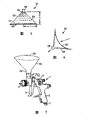
Fig. 1 is the view of a prior art paint sprayer 1 of the gravity transmission type that disclosed in disclosed our patent application to be examined of patent No. WO 98/32539, and the disclosure of this patent is incorporated herein by reference.
Spray gun 1 comprises a body 2, the one handle 3 that extends from the rear end of body downwards and at a nozzle 4 of the front end of body.This spray gun 1 is by a trigger 5 manual operationss, and this trigger is pivotably mounted on the both sides of spray gun.
A canister 6 that includes the paint (or similar material) that will penetrate by spray gun be positioned at body the top and with extend through the inner passage (can't see) that spray gun arrives nozzle 4 and be communicated with.
In use, spray gun 1 is connected in the compressed air source (not shown) by a connection piece 7 in the lower end of handle 3, thereby when the user spurred on trigger 5, compressed air was sent to nozzle 4 by spray gun.Thereby the paint that is sent to nozzle 4 from jar 6 under the gravity effect is atomized and forms a compressed-air actuated injection that has from nozzle 4 when leaving nozzle 4.
Consult Fig. 2 to 4 of accompanying drawing now, canister 6 comprises an outer container 8, disposable liner 9, disposable lid 10 and a lasso 11.The shape of liner 9 has a narrow edge 12 corresponding to the medial surface (and closely cooperating therein) of container 8 with at open end, and this edge is seated on the top margin of container 8.
By annular collar 11 lid 10 is firmly held in the appropriate location of container 8, this annular collar is tightened on the container 8, be on the top of lid 10 with screw thread.In confined state, dress will be sent to the paint of nozzle 4 or a storage liquid container of other liquid by tube connector 15 in liner 9 and lid 10 formed.
By using a fastener 18 that canister 6 is connected in spray gun 1, this fastener at one end 19 inside is formed with another part that the bayonet socket of the tube connector 15 that is used to be connected to lid 10 connects.At the other end 20, the shape of fastener 18 is consistent with the standard connection (being generally screw thread) of gun oil paint can.
In order to use canister 6,20 are connected in fastener 18 spray gun and allow it be in the appropriate location in the end.Then, for as the canister taken 6 of Fig. 2, liner 9 is pushed the inside of container 8 as showing.Then paint is poured in the liner 9, if desired, mixed with other colouring agent, thickening agent and diluent (solvent).Then lid 10 is pushed the appropriate location and tighten lasso 11 downwards, so that lid 10 is remained on the appropriate location.
Then with routine operation out of position come of spray gun 1 from shown in Figure 1 it, so that canister 6 can overflow to prevent paint with a vertical position towards spray gun 1.End with tube connector 15 is connected in fastener 18 then, removably canister 6 is fixed in spray gun 1.Then spray gun 1 is turned back to its normal operation position, so that use in due form.
In use, along with paint is extracted out from this storage liquid container, liner 9 is 10 axially cave in from cardinal extremity 9A along lid.Passage 8A permission air when liner 9 caves in the cardinal extremity of container 8 enters container 8.The sidewall 9B of liner 9 inwardly unfolds with at random not controlled way along with liner 9 caves in.This can be formed in the little bag shape of holding back in the liner 9 and keeping painting and has stoped whole paint to be sent to spray gun 1.
After using, when wanting cleaning spray gun 1, the operating position of spray gun 1 from shown in Figure 1 it can be reversed again, remove air hose and drive trigger 5 tout court, flow back in the liner of leading in the jar 69 to allow the paint in spray gun 1.Then by removing tube connector 15 and pull down jars 6 from spray gun 1 from remaining on fastener 18 on the spray gun 1.
Pull down lasso 11 from container 8, pull out lid 10 then, take the liner that caves in it away, keep container 8 and lasso 11 to re-use with a new liner 9 and a lid 10 with preparing for clean conditions.Only spray gun 1 self needs to clean, and its result has reduced the quantity of employed solvent significantly.
By sealed joint pipe 15, for example use a removable cap (not shown), can preserve any paint of staying in the liner 9 in a short-term.Lid/liner assembly and container 8 and lasso 11 can be refilled then and be equipped with and be connected in again spray gun 1, to use remaining paint.
When container 8 is pulled down, lid/liner assembly is more fragile, and if maloperation be easy to separately liner 9 and lid 10.Therefore, common practice is only to preserve untapped paint several hours, if store and must pour any untapped paint into another container gently the period of rectificating.If when using whole paint or no longer need any remaining paint, the liner 9 that can abandon lid 10 (comprising filtration members 17) and cave in.
The structure that disposable liner 9 and independent, disposable lid 10 form a storage liquid container that includes the paint of wanting injected or other liquid has reduced desired cleaning amount when injected liquid is wanted in transposing or when working day, spray gun was deposited in end significantly.This is must provide many benefits with a significant improvement of the configuration aspects of storage liquid container with to the user by cleaning spray gun therein.
But, be apparent that in order correctly to assemble many members so that normally play a role and reduce the danger of leakage, with this storage liquid container with its annex is installed to spray gun and they may be time-consuming from the spray gun dismounting.
Consult Fig. 5 to 7 of accompanying drawing now, wherein show first embodiment, can should store liquid container with a plain mode and be assembled to spray gun according to disposable, the storage liquid container filled with in advance of the present invention.This storage liquid container is particularly suitable for not requiring the manufacturing and the supply of the liquid that mixes colours exactly, for example priming paint, varnish, solvent.
As shown in the figure, storage liquid container 51 has a rigid body 52 of taper, and this body is sealed by extendible, a flexible diaphragm 53 at the cardinal extremity of broad, and this diaphragm and body 52 have formed a chamber 54.Body 52 is provided with a hole 55 on the top with respect to diaphragm 53, this hole is led to and body 52 integrally formed gateways 56.
If liquid 57 is photosensitive, storage liquid container 51 can be opaque.Perhaps, stable if liquid 57 is light, body 52 can be transparent or translucent, to allow the liquid 57 in the eye test storage liquid container 51.Body 52 can also be provided with scale mark, with the volume of the liquid 57 of indication in storage liquid container 51.
The storage liquid container is used the liquid of introducing by gateway 56 to fill with in advance and is adhered to a rupturable film, foil lid (not shown) sealing gateway 56 for example by the outer end of crossing the gateway, with sealed liquid storing container 51.Perhaps, can seal this gateway by any other suitable mode, for example threaded cap, stopper or draw ring.After filling with storage liquid container 51, a filtration members (not shown) can be placed in the gateway 56, so that using storage liquid container 51, removing any solia particle when sending liquid 57.
Utilize formula
Wherein r is that the radius and the h of the cardinal extremity of body 52 are height of body 52, is determined the volume of storage liquid container by the size of body 52.For example, the height of 5 centimetres radius and 2.5 centimetres produces the volume of 65cc (cubic centimetre).As you will understand, can be configured to provide any required volume with storage liquid container 51 by the size that changes body 52.
Thereby, body 52 can be configured to provide a storage liquid container of the enough liquid 57 that can be kept for once using or repeatedly use.Storage liquid container 51 can be filled with substantially fully or not fill with slightly, store liquid container 51 and fully mixed liquid 57 before using by maybe shaking by the machine that stir inside with hand with permission with liquid 57.This had stored the occasion in some period at storage liquid container 51 before using may be useful and/or desirable.
When with liquid 57 perfusion storage liquid containers 51, diaphragm 53 forms a flat substantially substrate.In this mode, storage liquid container 51 be freely stand and can vertically stand in the substrate of supporting by the broad cardinal extremity of rigid body 52.This provides to be used to supply and to store and has filled with storage liquid container 51 in advance and reduce diaphragm 53 by unexpectedly or a special stable structure of the risk that is punctured of improper heart.
Before connecting storage liquid container 51, puncture or remove the rupturable film of sealing gateway 56.Perhaps, in the time will storing liquid container 51 and be connected in spray gun 1, can automatically pierce through this film.
The size and dimension of rigid body 52 is determined to be in the cardinal extremity with storage liquid container 51 is connected in spray gun 1 or the user can grip when it is dismantled.In this mode, the liquid 51 when connection/dismounting storage liquid container 51 in the storage liquid container 51 is pressurized not, thereby reduces the risk of leaking/overflowing.
In use spray gun 1, along with liquid 57 is extracted out from storage liquid container 51 by gateway 56, to cross and on diaphragm 53, produce a pressure differential, this causes that diaphragm extends internally and bending towards outlet, as shown in Figure 6.This allows by preventing that formation vacuum, liquid 57 can not have the outflow of interrupting stably from storage liquid container 51 in storage liquid container 51.In addition, diaphragm 53 has sufficient elasticity, so that along with liquid 57 is drawn out of, diaphragm 53 extends and the inner surface that little by little contacts rigid body 52 with a controlled way.
Under the state that caves in fully shown in dotted lines in Figure 6, diaphragm 53 is basic consistent with the interior shape of rigid body 52.This helps to prevent that formation can be held back any little bag shape of liquid 57 in storage liquid container 51, thereby if guarantees that requirement can discharge all liquid 57 substantially fully.Afterwards, diaphragm 53 can turn back to its original form when stopping to spray.
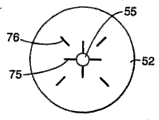
Improve in the pattern one, body 52 can be suitable for preventing diaphragm closed orifices 55 at liquid when the storage liquid container is extracted out, so that can discharge last liquid.For example, as shown in Figure 22 and 23, body 52 can be provided with around the rib 76 of the rib 75 of aperture 55 radially-arranged a plurality of projections and additional a plurality of projections of being provided with between a plurality of ribs 75 or in a plurality of rib 75 radial outward.Rib 75,76 provides any liquid flow path that flows to aperture 55 from storage liquid container 51.In this mode, rib 75,76 allows last liquid inwardly to be released and to prevent along with diaphragm 53 that towards the aperture 55 apertures 55 when caving in are closed.Can change quantity, shape and the position of rib 75,76 from the state shown in the figure, to be provided for any required flow channel that liquid flows to aperture 55.
Perhaps, as shown in figure 24, body 52 can be provided with cardinal extremity from broad to the aperture a spiral flow channel 77 of 55.In this mode, passage 77 provides about a path of wanting d/d final liquid and inwardly prevents along with diaphragm that towards the aperture 55 apertures 55 when caving in are closed.Can change the shape and the position of passage 77 and more than one passage 77 can be provided, arrive aperture 55 from any part of storage liquid container 51 to allow liquid.
Will appreciate that any other suitable structure can be set, to guarantee keeping unimpeded about a path of the final liquid that will discharge.
One dismountable closure cap (not shown) can be set, be used for fixing to the gateway 56, if before preventing before using storage liquid container 51, unexpectedly or by accident piercing through rupturable film and/or discharging whole liquid 57, sealed again to allow storage liquid container 51 from spray gun 1 dismounting.In this mode, can with any untapped fluid storage in storage liquid container 51 with will store liquid container 51 afterwards and be connected in spray gun 1 again, be used for further use.The overall structure that has the storage liquid container of the diaphragm 53 that is adhered to body 52 is strong and the long term storage that allows the untapped paint in storage liquid container 51, and the risk of not overflowing and leaking.
The multiple variation pattern of above-mentioned storage liquid container 51 has been shown in Fig. 8 to 10, has wherein used identical label to represent identical part.
In Fig. 8, show another shape of storage liquid container 51, wherein rigid body 52 has a conical upper 52a and a cylindrical lower part 52b, and has the diaphragm 53 of the cardinal extremity that is fixed in bottom 52b.This shape of body 52 also can freely stand, and the volume of storage liquid container 51 is increased and do not increase the radius of conical portion 52a, still allow simultaneously diaphragm 53 along with liquid from 51 extractions of storage liquid container and deflection enters body 52.This can be desirable there being a tapering part of long radius can make the unstable and occasion that is difficult to use of spray gun 1 very much.Can adopt that to have other shape of storage liquid container of freely standing body 52 and diaphragm 53 be clearly for those skilled in the art.
In Fig. 9, show storage liquid container 51 and have a stopple 60 in the wall of rigid body 52, self-packing elastomeric material.Stopple 60 allows with a syringe one liquid to be added in the liquid of storing in the liquid container 57.This may desiredly have the occasion that two liquid must mix before using, and for example a thickening agent or activator is added into a basic liquid.Perhaps, can use the liquid that added to improve the characteristic of the basic liquid in the storage liquid container, for example add colouring agent with the color (tone) that changes a priming coat or diluent (solvent) with change one final bright multiple layer for example varnish viscosity, be used for " fading out " or " colour mixture ".
In Figure 10, show the storage liquid container 51 have cardinal extremity pass to an annular lip 71 one in shoulder 70.Diaphragm 53 is fixed in shoulder 70 and flange 71 provides about storing the support substrate of liquid container 51.Flange 71 can be continuous or center on a series of discontinuous projectioies of separating of cardinal extremity.In this mode, storage liquid container 51 can stand on the surface vertically, and diaphragm 53 separates with this surface, with stability and the further risk that punctures film 53 by accident or unexpectedly that reduces of improving storage liquid container 51.
(not shown) in another version, we can provide the Ji Gai on the cardinal extremity that is assemblied in storage liquid container 51, with protection diaphragm 53 when not using storage liquid container 51.When storage liquid container 1 was connected in spray gun 1, basic lid can be dismountable, diaphragm 53 is exposed to storage liquid container 51 atmosphere outside pressure.Perhaps, basic lid can be provided with at least one hole, so that diaphragm 53 is exposed to atmospheric pressure.In about a variation pattern (not shown) again that uses the storage liquid container with a pressure conveying type spray gun, this hole can allow to connect the air that flows out from the pressure air supply line that arrives spray gun, diaphragm is exposed to a normal pressure that is higher than atmospheric pressure.
Consult Figure 11 and 12 of accompanying drawing now, wherein show according to disposable one second embodiment that fills with the storage liquid container in advance of the present invention, it can be assembled to spray gun with a plain mode.Be similar to the foregoing description, this storage liquid container is particularly suitable for not requiring the manufacturing and the supply of a liquid that tower exactly mixes colours, for example priming paint, varnish, solvent.For convenience, the label in the use series 100 is represented the part corresponding to second embodiment of first embodiment.
Figure 11 illustrates the extension that is in it or that fill with state and figure 12 illustrates be in it cave in or with the storage liquid container 151 of dummy status.Storage liquid container 151 have taper a rigid body 151 and one inextensible, flexible, also be the diaphragm 153 of taper, and form a chamber 154.
The taper cardinal principle of diaphragm 153 is corresponding to the interior tapered of body 152.As shown in the figure, the top of body 152 is for connecting the truncate end of gateway 156.Diaphragm 153 has similar truncate top, and this top forms a basic plane surface 158, and storage liquid container 151 can rely on this plane vertically to stand when injecting with liquid 157 if desired.
At extended position shown in Figure 11, roughly around a centre line C L symmetry, the cardinal extremity of body 152 is connected in the cardinal extremity of diaphragm 153 to the inner surface of chamber 154 in this centerline.In this mode, for certain height and radius of body 152, the volume of chamber 154 is the twice of first embodiment shown in Fig. 5 to 7 basically.
In the use of spray gun 1, along with liquid 157 is extracted out from storage liquid container 151 by gateway 156, on diaphragm 153, produce a pressure reduction, this pressure reduction causes its inwardly 156 distortion towards the gateway, shown in the outline line among Figure 12.This allow by prevent from storage liquid container 151, to form vacuum, from storing liquid container 151 trickle 157 without interruption evenly.In addition, along with liquid 157 is emitted, diaphragm 153 is flexible fully, little by little to contact the inner surface of rigid body 152.In the state that caves in fully shown in Figure 12, diaphragm 153 is reverse and basic consistent with the interior shape of rigid body 152 from its original state.This helps to prevent that formation can be held back any little bag shape of liquid 157 in storage liquid container 151, thereby can discharge all liq 157 substantially fully if desired.Body 152 can be suitable for providing and prevents that aperture 155 is by a path of complete closed with allow to discharge last liquid along with diaphragm 153 caves in as previously discussed.
One dismountable closure cap (not shown) can be set, for fixing to gateway 156, to prevent before using storage liquid container 151, piercing through rupturable film by accident or unexpectedly.Perhaps or additionally, if pulled down from spray gun 1 before discharging whole liquid 157, it is sealed again that this closure cap can allow to store liquid container 151.In this mode, any untapped liquid can leave in the storage liquid container 151 and store liquid container 151 later on and be connected in spray gun again, is provided with the back and uses.Equally, the overall structure of storage liquid container 151 is convenient to any untapped paint of a secured fashion long term storage.
Figure 13 to 15 shows a plurality of modified version of above-mentioned storage liquid container 151 shapes, and wherein identical label is represented corresponding part.
In Figure 13, the inner surface of rigid body 152 and diaphragm 153 that can be reverse is tetrahedron shapes of butt.Also can use other butt shape, for example pyramid that have many planar side.
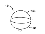
In Figure 14, the inner surface of rigid body 152 and diaphragm 153 that can be reverse is a hemispherical.With the taper ratio of Figure 11, can use hemispherical to increase volume significantly usually for the storage liquid container 151 of a certain radius.Diaphragm 153 can be provided with a flat primary surface, and storage liquid container 151 if desired is used for standing vertically.
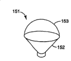
In Figure 15, the inner surface of rigid body 152 is frustoconical and diaphragm 153 that can be reverse is hemisphericals.The hemispherical of diaphragm 153 has increased the volume of storage liquid container 151 and has been similar to the inner surface of rigid body 152 fully, and is consistent with the inner surface of rigid body 152 with permission diaphragm 153 in the state of caving in.
Can use that diaphragm 153 basic other shapes consistent with the inner surface of rigid body 152 will be clearly for those skilled in the art in the state of caving in.
Referring now to Figure 16 to 19 of accompanying drawing,, show one the 3rd embodiment according to the of the present invention one storage liquid container of filling with in advance that can cave in, a valve gear wherein is set, be used to control paint flowing from the storage liquid container.The structure of this storage liquid container and class of operation are similar to second embodiment, and will be understood that this structure and operation from the narration of second embodiment.For convenience, the like numerals will in the use series 200 is represented the part corresponding to the 3rd embodiment of second embodiment.
In this embodiment, gateway 256 is provided with a valve gear 280, is used to control paint flowing from storage liquid container 251.Valve gear shown in Figure 16 200 is used for sealing storage liquid container 251 for closed condition, and be open mode in Figure 17, paint to allow to extract out from storage liquid container 251.
Be engaged on by the relative axially extended rib 286 of two diameters on the outer surface of gateway 256 in the two groove (not shown) of axially aligning of the complementation in the inner surface of sleeve 283, on gateway 256, rotate to prevent sleeve 283.
The rib 286 that extends from the base portion of gateway 256 has just extended on half height, and gateway 256 is provided with an outer annular protrusion 287 near upper ends.This two groove from the base portion of sleeve 283 extend on half height just and terminate in the hole portion 289 that passes to magnifying diameter one in shoulder 288.
Each arm 290 is provided with that separate and end at a upright maintenance hook 292 of a bump 293 at upper end with sleeve 283, and this bump has an inclined surface 294 relative with sleeve 283, and this inclined surface guides to the recessed lock rib in a bottom 295.
As Figure 21 clearly shown in, flange 300 has two cylindrical main grooves 301 along the couple positioned opposite of its periphery, passes through with the bump that allows maintenance hook 292 when sleeve 283 is pushed in the end of fastener 296 293.Can rotate storage liquid container 251 with respect to fastener 296 then, cause to keep hook 292 engagement with cams shape juts 302, this part makes hook 292 to extrinsic deflection.Jut 302 guides to cylindrical little groove 303 and hook 292 is received within the groove 303, lock rib 295 is positioned on the surface 304 of flange 300, axially remains on the fastener 296 will store liquid container 251.
By manual clamping finger-like retained part 291 with towards body 252 pulling arms 290, can discharge maintenance hook 292, pull down from fastener 296 will store liquid container 251.This causes and keeps hook 292 towards extrinsic deflection, so that lock rib 295 is disengaged the surface 304 of part 296, and allows sleeve 283 to be drawn out fastener 296, thereby pulls down storage liquid container 251.
In use, fastener 296 be fixed in spray gun 1 and by in the end that sleeve 283 is pushed fastener 296 and rotate storage liquid container 251, with engagement lock rib 295 these fasteners be fixed to be connected with the valve 280 of closing fill with storage liquid container 251 in advance.Can put upside down the storage liquid container 251 that has the valve 280 of closing, so that be connected in spray gun 1, spray gun is in the upright use location of its routine simultaneously, and does not paint any risk of overflowing from the storage liquid container.
In this mode, will store when liquid appearance 251 is connected in spray gun 1 does not need to put upside down spray gun 1, thereby is convenient to storage liquid container 251 is connected in spray gun 1.Wherein must put upside down spray gun 1 and be connected the storage liquid container from the below when especially, will appreciate that in case paint requires less hand skill from the arrangement that the storage liquid container overflows from spray gun 1 top assembling storage liquid container 251.
As you will understand, the action maintaining valve device 280 that storage liquid container 251 is locked in the promotion of fastener 296 and rotation is in the closed position, as shown in figure 16.When needs began to spray, by with the direction pulling body 252 that leaves spray gun 1, valve gear 280 is moved to open position as shown in figure 17, gateway 256 moved axially with respect to sleeve 283.Can be sent to spray gun 1 with paint by the hole 285 in the end wall 284 of aperture in the gateway 256 and sleeve 283 by foregoing spray gun 1 then.
Finish in case spray, can put upside down spray gun 1, oppositely flow into storage liquid container 251 to allow paint.Then by promote body 252 towards spray gun 1, piston part 282 relocated hole 285 in and to seal aperture in the end of gateway 256, valve gear 280 can be turned back to closed position as shown in figure 16.By towards body 252 pulling finger-like retained parts 291, to discharge lock rib 295 as previously mentioned, can store liquid container 251 then from spray gun 1 dismounting.Continue pulling finger-like retained part 251 then, so that sleeve 283 is disengaged part 296 and can dismantles the storage liquid container.
If can understand like that, the action of pulling finger-like retained part 291 at first from fastener 296 discharge lock rib 295 and then from fastener 296 pulling off sleeves 283, to keep valve gear 280 in the closed position.
When from spray gun 1 dismounting storage liquid container 251, it can be put if desired on one side, to store any untapped paint, use after being provided with or abandon it.When in storage liquid container 251, storing unspent paint so that re-using, can wipe clear piston part 282 in case any paint drying and prevent from when needs re-use stored paint, to provide pollution sources.This prevents when storage liquid container 251 is connected in spray gun 1 again that also any paint is dry and prevent that valve gear 280 is opened.Valve gear 280 also prevents the intrusion of any external contamination thing to paint in the time of in paint is stored in storage liquid container 251.
Will appreciate that valve gear 280 can be with using according to of the present invention, foregoing any other storage liquid container 51,151.Also will appreciate that according to any feature of a plurality of embodiment of storage liquid container 51,151,251 of the present invention and can use individually or in combination with any other embodiment.
For example, can use about storing maintenance hook 296 replacement bayonet arrangement and fastener 18 fixing any other storage liquid containers 51,151 that liquid container 251 is fixed in the spray gun 1 that has fastener 296.Salable plug 60 in the body 52 of the storage liquid container 51 shown in Fig. 9 can be arranged in the body 152,252 of other storage liquid container 151,251.Flange 71 as shown in figure 10 or the ledge that dangles can be arranged on the body 152,252 of any other liquid storage container 151,251, be provided for a upright state stand the storage liquid container 151,251 a non-yielding prop.
In the above-described embodiments, storage liquid container 51,151,251 contains a single liquid, and has the selectivity of a salable plug of a single admission in the wall that is provided at rigid body, that be used to introduce another composition.But, will appreciate that the storage liquid container can have a plurality of internal chamber of being separated by a rupturable film, thereby can store a plurality of reaction compositions individually and just before using, mix them.
As will appreciate that now, the invention provides the storage liquid container of simple structure, it with one reliably, controlled way can cave in, to guarantee to be released in the basic whole liquid in this storage liquid container.And the structure of the flexible membrane that enters a rigid body of can caving in can be filled with at the storage liquid container, part is filled with and keep the stability of this storage liquid container on spray gun when empty.Therefore, the storage liquid container can be connected in spray gun, partly is used, and dismounting, storage are provided with the back use and abandon when using up or no longer need.
The present invention also provides and has been particularly suitable for being supplied to the storage liquid container end user, that usefulness wants d/d liquid to fill with in advance.In this mode, the end user only need select and be connected this suitable storage liquid container, and this storage liquid container can be disassembled and storage is used after being provided with or abandoned after using.Therefore, avoided and the harm of handling that this liquid is associated, and after using, only required cleaning spray gun user's health.
But, will appreciate that the present invention is not limited to about being supplied to end user's the storage liquid container of filling with in advance.Thereby, the benefit of above-described, as to guarantee to discharge substantially fully liquid storage liquid container and advantage can be applied to the end user is supplied empty so that perfusion and is connected in the storage liquid container of spray gun.
Will appreciate that above-described exemplary embodiment is to be used to illustrate multiple scope of the present invention and application, and the feature of the foregoing description can be used individually or be used in combination with any further feature of identical or different embodiment.
Will appreciate that the present invention is not limited to these exemplary embodiments, and can make many variations and modification in described generally the principle and scope of the present invention as this paper.
Claims (18)
1. storage liquid container (51 that uses with a liquid injection device, 151,251), this stores liquid container (51,151,251) has the first (52 of a substantially rigid that is connected in described liquid injection device releasedly, 152,252), wherein said first (52,152,252) inner surface extends between the following cardinal extremity wideer than top on this of top on one and one and has the aperture (55 that can extract the liquid that is used to be supplied to this equipment by it, 155,255), described aperture top end on described is used for storage liquid container (51,151,251) be connected in described equipment, described storage liquid container also has the second portion (53 of a flexibility that has an inner surface, 153,253), this inner surface and first (52,152,252) a inner surface forms a chamber (54 that is installed in this liquid together, 154,254), it is characterized in that: the second portion (53 of described flexibility, 153,253) with described aperture (55,155,255) relative following cardinal extremity place, and be configured in use along with from chamber (54,154,254) extract liquid out and dwindle chamber (54,154,254) volume, and at storage liquid container (51,151,251) an inner surface unanimity of caving in basic and first (52,152,252) in the state, wherein the aperture (55,155,255) be configured to: in use substantially can be storage liquid container (51,151,251) whole liquid contained in are released into liquid injection device, and by making flexible second portion (53,153,253) and first (52,152,252) inner surface is consistent and reduce form the little bag shape of holding back liquid in storage liquid container (51,151,251).
2. according to the described storage liquid container of claim 1, it is characterized in that: first (52,152,252) and second portion (53,153,253) are individually formed and combination for good and all, to form storage liquid container (51,151,251).
3. according to the described storage liquid container of claim 1, it is characterized in that: first (52,152,252) and second portion (53,153,253) integral body form as one.
4. according to the described storage liquid container of claim 1, it is characterized in that: the inner surface of first (52,152,252) is a straight line in axial cutaway view.
5. according to the described storage liquid container of claim 1, it is characterized in that: the inner surface of first (152) is chosen from comprise taper, tetrahedroid, pyramid or other polygonal graphical set.
6. according to the described storage liquid container of claim 1, it is characterized in that: the inner surface of first (152) is curve in axial section.
7. according to claim 1 or the described storage liquid container of claim 6, it is characterized in that: the inner surface of first (152) is the part sphere.
8. according to the described storage liquid container of claim 1, it is characterized in that: second portion (53) comprises the flexible sheet (53) that extensible material is made.
9. according to the described storage liquid container of claim 8, it is characterized in that: diaphragm (53) is provided in liquid and fills with the storage liquid container when (51), and the following cardinal extremity that crosses first (52) extends into a flat substantially state.
10. according to the described storage liquid container of claim 9, it is characterized in that: storage liquid container (51) can stand into the upright state by the cardinal extremity supporting of first (52).
11., it is characterized in that according to the described storage liquid container of claim 9: in use, when liquid from storage liquid container (51) when being drawn out of, diaphragm (53) towards the aperture (55) inwardly stretch and be out of shape, to dwindle the volume of chamber (54).
12., it is characterized in that according to the described storage liquid container of claim 1: second portion (153,253) comprises that inextensible substantially material makes can be reverse diaphragm (153,253).
13., it is characterized in that: when filling with storage liquid container (151,251) with liquid according to the described storage liquid container of claim 12, diaphragm (153,253) cardinal extremity that leaves first (152,252) extend and with the inner surface minute surface symmetry of first (152,252).
14. according to the described storage liquid container of claim 13, it is characterized in that: the top of diaphragm (153,253) is flat, so that a substrate surface to be provided, consequently storage liquid container (151,251) can stand into a upright state when filling with liquid.
15. each described storage liquid container according to claim 12 to 14, it is characterized in that: in use, the storage liquid container (151 that diaphragm (153,253) is being filled with liquid, one of the storage liquid container (151,251) of an extension state 251) and sky caves in can be reverse between the state.
16. each described storage liquid container according to claim 12 to 14, it is characterized in that: with passing through gateway (56,156,256) liquid of Yin Ruing is filled with storage liquid container (51,151,251), and sealing gateway (56,156,256) is with sealed liquid storing container (51,151,251) be assembled to spray gun (1) until storing liquid container.
17. according to the described storage liquid container of claim 16, it is characterized in that: gateway (256) are provided with a manual exercisable valve (280), are used to open and close gateway (256).
18. according to the described storage liquid container of claim 17, it is characterized in that: when storage liquid container (251) was fixed in spray gun (1), valve (280) was operated.
Applications Claiming Priority (2)
| Application Number | Priority Date | Filing Date | Title |
|---|---|---|---|
| GBGB0210446.1A GB0210446D0 (en) | 2002-05-08 | 2002-05-08 | Conformable pouch reservoir for spray gun |
| GB0210446.1 | 2002-05-08 |
Publications (2)
| Publication Number | Publication Date |
|---|---|
| CN1658976A CN1658976A (en) | 2005-08-24 |
| CN100421811C true CN100421811C (en) | 2008-10-01 |
Family
ID=9936217
Family Applications (1)
| Application Number | Title | Priority Date | Filing Date |
|---|---|---|---|
| CNB038136740A Expired - Fee Related CN100421811C (en) | 2002-05-08 | 2003-05-01 | Conformable pouch reservoir for spray gun |
Country Status (13)
| Country | Link |
|---|---|
| US (3) | US6942126B2 (en) |
| EP (1) | EP1507596B1 (en) |
| JP (1) | JP4477488B2 (en) |
| CN (1) | CN100421811C (en) |
| AT (1) | ATE448027T1 (en) |
| AU (1) | AU2003232033A1 (en) |
| CA (1) | CA2484785A1 (en) |
| DE (1) | DE60330000D1 (en) |
| ES (1) | ES2335400T3 (en) |
| GB (1) | GB0210446D0 (en) |
| RU (1) | RU2362630C2 (en) |
| TW (1) | TWI280157B (en) |
| WO (1) | WO2003095100A1 (en) |
Families Citing this family (54)
| Publication number | Priority date | Publication date | Assignee | Title |
|---|---|---|---|---|
| US7665672B2 (en) * | 2004-01-16 | 2010-02-23 | Illinois Tool Works Inc. | Antistatic paint cup |
| US7165732B2 (en) | 2004-01-16 | 2007-01-23 | Illinois Tool Works Inc. | Adapter assembly for a fluid supply assembly |
| US7086549B2 (en) * | 2004-01-16 | 2006-08-08 | Illinois Tool Works Inc. | Fluid supply assembly |
| DE102004007733B4 (en) * | 2004-02-16 | 2014-02-13 | Sata Gmbh & Co. Kg | Gravity cup for a paint spray gun |
| US7766250B2 (en) | 2004-06-01 | 2010-08-03 | Illinois Tool Works Inc. | Antistatic paint cup |
| US7757972B2 (en) | 2004-06-03 | 2010-07-20 | Illinois Tool Works Inc. | Conversion adapter for a fluid supply assembly |
| US7353964B2 (en) | 2004-06-10 | 2008-04-08 | Illinois Tool Works Inc. | Fluid supply assembly |
| ES2273198T3 (en) * | 2004-07-02 | 2007-05-01 | Flexi-Cup | FLEXIBLE CONTAINER SUITABLE FOR PAINTING. |
| CA2595507C (en) | 2004-12-16 | 2014-08-12 | Louis M. Gerson Co., Inc. | Liquid supply cup and liner assembly for spray guns |
| US20110258825A1 (en) * | 2005-02-24 | 2011-10-27 | Johnston Matthew L | Spray gun modifications for polymeric coating applicators |
| NL1028575C2 (en) * | 2005-03-18 | 2006-09-20 | Emm Productions B V | Disposable cup for a paint sprayer and paint sprayer fitted with it. |
| US20070095943A1 (en) | 2005-10-28 | 2007-05-03 | Turnbull William N | Liquid reservoir, and kit, spray assembly and method using same |
| US20110089261A1 (en) * | 2006-02-11 | 2011-04-21 | Goehring Alfred | Spray gun assembly |
| US20070241138A1 (en) * | 2006-04-13 | 2007-10-18 | Knott Joe H | Grout applicator |
| US11040360B2 (en) | 2006-06-20 | 2021-06-22 | Saint-Gobain Abrasives, Inc. | Liquid supply assembly |
| ES2400161T3 (en) | 2006-06-20 | 2013-04-08 | Saint-Gobain Abrasives, Inc. | Liquid supply set |
| DE502007000825D1 (en) | 2006-12-05 | 2009-07-16 | Sata Gmbh & Co Kg | Ventilation for the gravity cup of a paint spray gun |
| DE102008000394A1 (en) * | 2008-02-25 | 2009-08-27 | Robert Bosch Gmbh | A spray gun system |
| JP2011519307A (en) | 2008-03-12 | 2011-07-07 | ジェフリー ディー フォックス | Disposable spray gun cartridge |
| US20090272819A1 (en) * | 2008-04-30 | 2009-11-05 | Illinois Tool Works Inc. | Disposable liquid paint reservoir with internal support member for use with paint spray guns |
| DE202008014389U1 (en) | 2008-10-29 | 2010-04-08 | Sata Gmbh & Co. Kg | Gravity cup for a paint spray gun |
| WO2010084140A1 (en) | 2009-01-23 | 2010-07-29 | Akzo Nobel Coatings International B.V. | Packaging for two or more fluids |
| DE102009032399A1 (en) | 2009-07-08 | 2011-01-13 | Sata Gmbh & Co. Kg | Spray Gun |
| DE202010007355U1 (en) | 2010-05-28 | 2011-10-20 | Sata Gmbh & Co. Kg | Nozzle head for a spraying device |
| US10286414B2 (en) * | 2010-07-12 | 2019-05-14 | Carlisle Fluid Technologies, Inc. | Liquid supply container for a spray coating device |
| US8962093B2 (en) | 2010-11-01 | 2015-02-24 | Milspray Llc | Spray paint application system and method of using same |
| US9333519B2 (en) | 2010-12-02 | 2016-05-10 | Sata Gmbh & Co. Kg | Spray gun and accessories |
| WO2012154624A2 (en) | 2011-05-06 | 2012-11-15 | Saint-Gobain Abrasives, Inc. | Paint cup assembly with a collapsible liner |
| MX371278B (en) | 2011-06-30 | 2020-01-24 | Saint Gobain Abrasifs Sa | Paint cup assembly. |
| RU2601337C2 (en) | 2011-06-30 | 2016-11-10 | САТА ГмбХ унд Ко. КГ | Paint spray gun with possibility of easy cleaning, accessory for paint spray gun and method of their assembly and disassembly |
| EP2771127B1 (en) | 2011-10-27 | 2017-07-12 | Graco Minnesota Inc. | Sprayer fluid supply with collapsible liner |
| EP2797697B1 (en) | 2011-12-30 | 2020-11-04 | Saint-Gobain Abrasives, Inc. | Convertible paint cup assembly with air inlet valve |
| US20140050513A1 (en) * | 2012-08-19 | 2014-02-20 | Steven Wilcox | Mortar Application Device |
| US9205442B2 (en) | 2012-10-09 | 2015-12-08 | Milspray Llc | Spray paint applicator |
| US9352343B2 (en) | 2013-01-22 | 2016-05-31 | Carlisle Fluid Technologies, Inc. | Liquid supply system for a gravity feed spray device |
| US9038674B2 (en) * | 2013-06-14 | 2015-05-26 | Sps Lid Technology Ii, Llc | Paint can cover assembly with paint return port |
| CA155474S (en) | 2013-09-27 | 2015-08-27 | Sata Gmbh & Co Kg | Spray gun |
| DE202013105779U1 (en) | 2013-12-18 | 2015-03-19 | Sata Gmbh & Co. Kg | Air nozzle termination for a paint spray gun |
| CN105289870B (en) | 2014-07-31 | 2019-09-24 | 萨塔有限两合公司 | Manufacturing method, spray gun, gun body and the lid of spray gun |
| USD758537S1 (en) | 2014-07-31 | 2016-06-07 | Sata Gmbh & Co. Kg | Paint spray gun rear portion |
| CA159961S (en) | 2014-07-31 | 2015-07-17 | Sata Gmbh & Co Kg | Spray gun |
| USD768820S1 (en) | 2014-09-03 | 2016-10-11 | Sata Gmbh & Co. Kg | Paint spray gun with pattern |
| US9796492B2 (en) | 2015-03-12 | 2017-10-24 | Graco Minnesota Inc. | Manual check valve for priming a collapsible fluid liner for a sprayer |
| DE102015006484A1 (en) | 2015-05-22 | 2016-11-24 | Sata Gmbh & Co. Kg | Nozzle arrangement for a spray gun, in particular paint spray gun and spray gun, in particular paint spray gun |
| USD810260S1 (en) * | 2015-12-16 | 2018-02-13 | Earl Vaughn Sevy | Circular, cylindrical, drop-in, modular diffuser |
| DE102015016474A1 (en) | 2015-12-21 | 2017-06-22 | Sata Gmbh & Co. Kg | Air cap and nozzle assembly for a spray gun and spray gun |
| CN106667596A (en) * | 2016-07-29 | 2017-05-17 | 山东大学 | Disposable multifunctional bone meal conveyer and working method thereof |
| CN205966208U (en) | 2016-08-19 | 2017-02-22 | 萨塔有限两合公司 | Hood subassembly and spray gun |
| CN205995666U (en) | 2016-08-19 | 2017-03-08 | 萨塔有限两合公司 | Spray gun and its trigger |
| DE102018118738A1 (en) | 2018-08-01 | 2020-02-06 | Sata Gmbh & Co. Kg | Base body for a spray gun, spray guns, spray gun set, method for producing a base body for a spray gun and method for converting a spray gun |
| US11826771B2 (en) | 2018-08-01 | 2023-11-28 | Sata Gmbh & Co. Kg | Set of nozzles for a spray gun, spray gun system, method for embodying a nozzle module, method for selecting a nozzle module from a set of nozzles for a paint job, selection system and computer program product |
| DE102018118737A1 (en) | 2018-08-01 | 2020-02-06 | Sata Gmbh & Co. Kg | Nozzle for a spray gun, nozzle set for a spray gun, spray guns and method for producing a nozzle for a spray gun |
| CN115739435A (en) | 2019-05-31 | 2023-03-07 | 固瑞克明尼苏达有限公司 | Hand-held fluid sprayer |
| CN117122854B (en) * | 2023-10-20 | 2024-01-02 | 常州蓝翼飞机装备制造有限公司 | Automatic triggering type fire extinguisher |
Citations (1)
| Publication number | Priority date | Publication date | Assignee | Title |
|---|---|---|---|---|
| EP0030076A1 (en) * | 1979-10-29 | 1981-06-10 | Pfizer Inc. | Purification of L-aspartyl-L-phenylalanine alkyl esters |
Family Cites Families (119)
| Publication number | Priority date | Publication date | Assignee | Title |
|---|---|---|---|---|
| DE588631C (en) * | 1933-11-21 | Emil Beck | Paint sprayer | |
| US1703384A (en) * | 1924-10-18 | 1929-02-26 | Matthews W N Corp | Paint gun |
| US2152862A (en) * | 1936-09-30 | 1939-04-04 | Bergerloux Rene | Container for dispensing materials |
| US2208744A (en) * | 1936-09-30 | 1940-07-23 | Georges Bardin | Container provided with a flexible diaphragm for dispensing materials |
| US2264564A (en) * | 1937-10-28 | 1941-12-02 | Connor Arthur Albert | Air brush for artists' use |
| US2177032A (en) * | 1938-06-14 | 1939-10-24 | Baumgardner Henry Charles | Spraying device |
| US3134494A (en) * | 1962-08-20 | 1964-05-26 | Paul N Quinn | Infant feeding device |
| US3227305A (en) * | 1963-08-09 | 1966-01-04 | Binks Mfg Co | Disposable liner |
| US3211324A (en) * | 1963-10-10 | 1965-10-12 | Raymond C Henery | Liner for paint receptacle of paint spray gun |
| US3236459A (en) * | 1963-12-16 | 1966-02-22 | Thomas P Mcritchie | Apparatus for spraying materials |
| US3198538A (en) * | 1964-01-20 | 1965-08-03 | Charles P Nowell | Dolly |
| US3198438A (en) | 1964-03-12 | 1965-08-03 | Hultgren | Sprayer construction |
| US3255972A (en) * | 1964-03-12 | 1966-06-14 | Hultgren | Disposable container |
| US3401842A (en) * | 1966-11-28 | 1968-09-17 | Betty L Morrison | Combination paint cup and filler for spray guns |
| US3757718A (en) * | 1966-12-13 | 1973-09-11 | Shell Oil Co | Method for forming hollow articles of work-stengthenable plastic materials |
| US3432104A (en) * | 1967-03-23 | 1969-03-11 | Theodore L Kaltenbach | Seal spray gun siphon cup |
| US3507309A (en) * | 1967-07-07 | 1970-04-21 | Harold D Johnson | Sprayer for hydrocarbon-containing liquids |
| US3773211A (en) * | 1970-08-13 | 1973-11-20 | H Bridgman | Uterine aspiration collection bag |
| US3784039A (en) | 1972-01-10 | 1974-01-08 | Illinois Tool Works | Nursing bottle construction and assembly |
| US3780950A (en) * | 1972-02-07 | 1973-12-25 | W Brennan | Paint accomodating modules adapted for use with spray guns |
| CH540159A (en) | 1972-02-11 | 1973-08-15 | Baillod Frederic | Plastics bowl - with removable liners |
| US3790021A (en) * | 1972-06-30 | 1974-02-05 | I Bailey | Plastic container with disposable inner container |
| US3790017A (en) * | 1972-08-08 | 1974-02-05 | Int Playtex Corp | Nursing unit |
| US3862708A (en) * | 1973-10-11 | 1975-01-28 | Horix Mfg Co | Container filling device with flow control |
| US3934746A (en) * | 1973-11-08 | 1976-01-27 | Lilja Duane F | Fluid product reservoir |
| CA1006450A (en) | 1974-05-14 | 1977-03-08 | Arthur C. Barr | Nursing unit with improved plastic liner |
| US4043510A (en) * | 1975-11-21 | 1977-08-23 | Morris William E | Non-aerosol type dispenser |
| US4151929A (en) * | 1976-07-09 | 1979-05-01 | Sapien Sisto V | Plastic liner with collar for a paint receptacle |
| HU171979B (en) * | 1976-07-19 | 1978-04-28 | Vilmos Weiperth | Spraying pistol |
| SE402753B (en) * | 1977-03-21 | 1978-07-17 | Jonsereds Fabrikers Ab | ARRANGEMENT OF HOSE LINING AND HYDROUL COUPLING FOR HYDRAULICLY MANUFACTURED CRANE |
| US4122973A (en) * | 1977-10-14 | 1978-10-31 | Ahern Paul B | Lined containers for paint and the like |
| US4193506A (en) * | 1978-05-15 | 1980-03-18 | Procter & Gamble Company | Disposable infant nurser |
| GB2041873B (en) * | 1978-08-31 | 1983-06-15 | Nippon Paint Co Ltd | Container for filling liquid |
| DE2900998C3 (en) | 1979-01-12 | 1982-01-21 | Josef Nittel KG, 6096 Raunheim | Lay-out and orientation cover for flexible container linings |
| JPS594922Y2 (en) * | 1979-02-15 | 1984-02-14 | 実 世取山 | Disposable inner container for paint mixing |
| DE2944653A1 (en) | 1979-11-06 | 1981-05-21 | Erich 7990 Friedrichshafen Roser | Thin-walled vessel tap connector device - has pin on mating piece opening spring-loaded valve when connected |
| US4379455A (en) * | 1980-01-21 | 1983-04-12 | Deaton David W | Medical receptacle with disposable liner assembly |
| US4321922A (en) * | 1980-01-21 | 1982-03-30 | Deaton David W | Medical receptacle with disposable liner assembly |
| IT1138756B (en) * | 1980-04-29 | 1986-09-17 | Ihmels Manfred | PRESSURE-OPERATED SPRAY GUN |
| US4339046A (en) * | 1981-01-26 | 1982-07-13 | Robert Coen | Nursing bottle |
| US4406406A (en) * | 1981-03-13 | 1983-09-27 | Knapp Philip B | Liquid metering and dispensing apparatus |
| DE3118207A1 (en) * | 1981-05-08 | 1982-11-25 | Lang Apparatebau GmbH, 8227 Siegsdorf | "SPRAYER" |
| FR2510069A1 (en) * | 1981-07-21 | 1983-01-28 | Blanie Paul | Liquid or paste distribution vessel - has valves integral with reservoir containing inlet and discharge passages |
| CH653574A5 (en) | 1983-01-11 | 1986-01-15 | Ehrensperger C Ag | Device for spraying flowable and liquid materials |
| JPS59153874U (en) * | 1983-03-30 | 1984-10-16 | 株式会社吉野工業所 | Creamy storage container |
| US4586628A (en) * | 1983-11-02 | 1986-05-06 | Josef Nittel Gmbh & Co Kg | Resilient inner liner for lining of transport or storage containers |
| DE3346165A1 (en) * | 1983-12-21 | 1985-07-11 | Heinrich Ihmels + Sohn, 2905 Edewecht | SPRAYER INSERT FOR SPRAY GUNS |
| DE3409961A1 (en) | 1984-03-17 | 1985-09-19 | Basf Farben + Fasern Ag, 2000 Hamburg | Apparatus for applying fluid samples, such as paints, pigments or the like |
| US4657151A (en) * | 1984-04-12 | 1987-04-14 | Baxter Travenol Laboratories, Inc. | Container such as a nursing container, with flexible liner |
| US4558792A (en) * | 1984-04-12 | 1985-12-17 | Baxter Travenol Laboratories, Inc. | Container such as a nursing container, with flexible liner and access site and method of making said access site |
| CA1192852A (en) | 1984-09-21 | 1985-09-03 | Lawrence W. Vallier | Disposable film plastic paint tray liners |
| DE3439442A1 (en) | 1984-10-27 | 1986-04-30 | Helga-Margot 7156 Wüstenrot Herrmann | Packaging container |
| DE3517122C1 (en) | 1985-05-11 | 1986-05-28 | Daimler-Benz Ag, 7000 Stuttgart | Basket-shaped or beaker-shaped receiving apparatus for paint containers on paint spray guns |
| EP0201683A1 (en) * | 1985-05-13 | 1986-11-20 | Jean Egli | A variable colorant blender |
| US4813556A (en) * | 1986-07-11 | 1989-03-21 | Globestar Incorporated | Collapsible baby bottle with integral gripping elements and liner |
| JPH0649447Y2 (en) * | 1987-03-30 | 1994-12-14 | トヨタ自動車株式会社 | Circuit for vehicle air suspension |
| CA1280109C (en) * | 1987-07-08 | 1991-02-12 | Laszlo Murzsa | Paint mixing container |
| IL87108A0 (en) * | 1987-07-20 | 1988-12-30 | Nomix Mfg Co Ltd | Equipment for delivering fluids |
| US4836764A (en) * | 1987-10-13 | 1989-06-06 | Questech Ventures Inc. | Melt-phase thermal pressure apparatus for forming of plastic blanks into retortable containers |
| US4760962A (en) * | 1987-10-30 | 1988-08-02 | The Devilbiss Company | Spray gun paint cup and lid assembly |
| US4813566A (en) * | 1987-12-28 | 1989-03-21 | Hewitt Frederick A | Mortuary record container and method of assembly |
| US5424086A (en) * | 1988-03-02 | 1995-06-13 | Walker; Rohan C. W. | Method of manufacturing disposable inserts for nursing bottles |
| DE68905881T2 (en) * | 1988-07-25 | 1993-08-19 | Cebal | METHOD FOR PRODUCING BAG DISPENSERS, CORRESPONDING PARTS AND DISPENSERS. |
| US4951875A (en) * | 1988-09-19 | 1990-08-28 | Devey Daniel A | Diposable liner system for spray guns |
| US5097540A (en) * | 1988-09-26 | 1992-03-24 | Lovitt Harold B | Self-contained hand-held bidet |
| US5069389A (en) * | 1988-10-31 | 1991-12-03 | Constantine Bitsakos | Adapter for an air spray paint gun |
| US4971251A (en) * | 1988-11-28 | 1990-11-20 | Minnesota Mining And Manufacturing Company | Spray gun with disposable liquid handling portion |
| US4936511A (en) * | 1988-11-28 | 1990-06-26 | Minnesota Mining And Manufacturing Company | Spray gun with disposable liquid handling portion |
| US4930644A (en) * | 1988-12-22 | 1990-06-05 | Robbins Edward S Iii | Thin film container with removable lid and related process |
| US5089389A (en) * | 1989-08-25 | 1992-02-18 | Eastman Kodak Company | Buffered composition, coated article test device and a method for their use |
| CA2099763C (en) | 1989-11-15 | 2001-07-24 | Jeff Martin | Fluid mixing accessory |
| DE69031630D1 (en) | 1990-01-26 | 1997-11-27 | Alberto Signorini | DISPOSABLE BOTTLE |
| GB2240610B (en) * | 1990-02-05 | 1993-12-08 | Devilbiss Co | Needle packing assembly |
| US5052623A (en) * | 1990-09-10 | 1991-10-01 | Nordeen Melvin A | Compartmentalized paint cup with selector valve for spray guns |
| FR2669306A1 (en) * | 1990-11-16 | 1992-05-22 | Kerplas Snc | Deformable pouch for bottle with filling and drawing off-pump |
| DE4102326A1 (en) | 1991-01-26 | 1992-07-30 | Gefinex Gmbh | Multi-purpose container, esp. plastics bucket - has removable, stick-on inner and/or lining |
| GB9101812D0 (en) | 1991-01-28 | 1991-03-13 | Morgan Crucible Co | Dispensing of fluids |
| US5143294A (en) * | 1991-04-08 | 1992-09-01 | Lintvedt Arnold M | Pliant container for storage of a liquid and liquid application therefrom |
| US5143242A (en) * | 1991-04-25 | 1992-09-01 | Millasich David S | Paint bucket with disposable liner |
| US5186828A (en) * | 1992-02-14 | 1993-02-16 | Mankin Gary L | Paint strainer kit |
| DE4209258A1 (en) | 1992-03-21 | 1993-09-23 | David Klaus Rosskamp | Paint waste and cleaning material collector - fits on spray gun nozzle opening and has stop valve and movable flap for cleaning material |
| DE4222836C2 (en) * | 1992-07-11 | 1997-07-10 | Karsten Gall | Containers for liquids or masses similar to liquids |
| US5454488A (en) * | 1992-11-24 | 1995-10-03 | Coster Technologie Speciali Spa Stabilimento Di Calceranica | Apparatus for dispensing a semifluid medium from a container |
| US5338921A (en) * | 1993-02-16 | 1994-08-16 | Universal Packaging Corporation | Method of distributing heat in food containers adapted for microwave cooking and novel container structure |
| US5328095A (en) * | 1993-04-08 | 1994-07-12 | Grumman Aerospace Corporation | Self-contained spray gun apparatus with spherical paint cup |
| WO1994026231A1 (en) * | 1993-05-11 | 1994-11-24 | Munchkin Bottling, Inc. | Disposable bottle bags for use with infant nursing systems |
| US5337921A (en) | 1993-05-17 | 1994-08-16 | Dowbrands Inc. | Detachable receptacle and fitted pouches for refillable sprayer devices |
| US5386251A (en) * | 1993-06-03 | 1995-01-31 | Zilog, Inc. | Television receiver with learning remote control system capable of being controlled by a remote control device manufactured by different companies |
| DE4325512A1 (en) | 1993-07-29 | 1995-02-02 | Nittel Gmbh & Co Kg | Container lining |
| US5460289A (en) * | 1993-10-14 | 1995-10-24 | Gemmell; Wayne R. | Paint tray assembly with disposable multi-layered liner |
| US5405030A (en) * | 1994-02-23 | 1995-04-11 | Frazier; Sara J. | Dual-compartment drinking cup |
| US5617972A (en) * | 1994-03-25 | 1997-04-08 | Playtex Products Inc. | Nurser liner |
| US5829588A (en) * | 1994-03-25 | 1998-11-03 | Bloomfield; Lawrence Michael | Sharps container |
| CA2143277C (en) | 1994-04-19 | 2000-05-16 | Michael J. Kosmyna | Hand held paint spray gun with top mounted paint cup |
| GB2290718B (en) | 1994-06-30 | 1998-07-01 | Cannon Rubber Ltd | Disposable baby bottle |
| USD366654S (en) * | 1994-07-26 | 1996-01-30 | Westinghouse Electric Corporation | Mousepad |
| US5655714A (en) * | 1994-12-08 | 1997-08-12 | Wagner Spray Tech Corporation | Pivotable syphon tube |
| FR2734247B1 (en) * | 1995-05-17 | 1997-06-27 | Oreal | DEVICE FOR PACKAGING AND DISPENSING A LIQUID OR PASTY PRODUCT |
| US5607082A (en) * | 1995-06-01 | 1997-03-04 | H. D. Hudson Manufacturing Company | Reusable compression sprayer utilizing a disposable collapsible bag |
| USD386654S (en) * | 1995-12-06 | 1997-11-25 | Ransburg Corporation | Zipper bag sealing tool |
| US5818501A (en) * | 1995-12-28 | 1998-10-06 | Eastman Kodak Company | Apparatus and method for grey level printing with improved correction of exposure parameters |
| US5789684A (en) * | 1996-01-16 | 1998-08-04 | Isco, Inc. | Liquid sample storage device |
| CH688082A5 (en) | 1996-03-15 | 1997-05-15 | Ugo Gervasi | Multicolour paint flow cup |
| DE19618514A1 (en) | 1996-05-08 | 1997-11-13 | Schreinerei U Moebelhandel Geo | Measurement beaker |
| US5797520A (en) * | 1996-09-24 | 1998-08-25 | Northrop Grumman Corporation | Metering system and method for use with fluids having a high solid content |
| US5816501A (en) * | 1996-12-16 | 1998-10-06 | Ransburg Corporation | Disposable paint container liner and method |
| US6820824B1 (en) * | 1998-01-14 | 2004-11-23 | 3M Innovative Properties Company | Apparatus for spraying liquids, disposable containers and liners suitable for use therewith |
| US5853102A (en) * | 1997-01-27 | 1998-12-29 | Jarrett; Guy R. | Insert for spray gun paint cups |
| US6019294A (en) * | 1997-05-23 | 2000-02-01 | Graco Inc | Interchangeable feed airspray/HVLP spray gun |
| US5808711A (en) * | 1997-08-22 | 1998-09-15 | Motorola, Inc. | Transparent or reflective liquid crystal display assembly with electrochromic and cholesteric layer |
| US6257429B1 (en) * | 1998-03-09 | 2001-07-10 | Carl Cheung Tung Kong | Drink dispenser for collapsible liquid containers |
| US6196410B1 (en) * | 1999-03-16 | 2001-03-06 | Contract Commercial Products | Paint tray liner with cover |
| DE29905100U1 (en) | 1999-03-20 | 1999-06-10 | Ruda Martin | Mixing cup system |
| DE29909950U1 (en) * | 1999-06-08 | 1999-09-23 | Chang Jen Chih | Spray gun container |
| AU3583899A (en) | 1999-06-24 | 2001-01-04 | Brian Eccles | Disposable paint tray liner |
| US6536687B1 (en) * | 1999-08-16 | 2003-03-25 | 3M Innovative Properties Company | Mixing cup adapting assembly |
| US6092740A (en) * | 1999-08-20 | 2000-07-25 | Liu; Horng-Hsiang | Structure of a paint container for spray gun |
| DE10126338A1 (en) * | 2001-05-30 | 2002-12-12 | Siemens Ag | High frequency coil arrangement for an NMR imaging device in which both surface and circumferential coils receive the same polarization component |
| DE20117496U1 (en) | 2001-10-25 | 2002-01-03 | Venjakob Maschinenb Gmbh & Co | Small quantity paint supply for a paint spraying system |
-
2002
- 2002-05-08 GB GBGB0210446.1A patent/GB0210446D0/en not_active Ceased
-
2003
- 2003-05-01 RU RU2004130872/12A patent/RU2362630C2/en not_active IP Right Cessation
- 2003-05-01 EP EP03750050A patent/EP1507596B1/en not_active Expired - Lifetime
- 2003-05-01 CN CNB038136740A patent/CN100421811C/en not_active Expired - Fee Related
- 2003-05-01 ES ES03750050T patent/ES2335400T3/en not_active Expired - Lifetime
- 2003-05-01 DE DE60330000T patent/DE60330000D1/en not_active Expired - Lifetime
- 2003-05-01 CA CA002484785A patent/CA2484785A1/en not_active Abandoned
- 2003-05-01 AT AT03750050T patent/ATE448027T1/en not_active IP Right Cessation
- 2003-05-01 WO PCT/US2003/013655 patent/WO2003095100A1/en active Application Filing
- 2003-05-01 JP JP2004503173A patent/JP4477488B2/en not_active Expired - Fee Related
- 2003-05-01 AU AU2003232033A patent/AU2003232033A1/en not_active Abandoned
- 2003-05-07 TW TW092112454A patent/TWI280157B/en not_active IP Right Cessation
- 2003-05-07 US US10/430,952 patent/US6942126B2/en not_active Expired - Lifetime
-
2005
- 2005-07-11 US US11/178,779 patent/US20050247804A1/en not_active Abandoned
-
2009
- 2009-05-11 US US12/463,669 patent/US20090218417A1/en not_active Abandoned
Patent Citations (1)
| Publication number | Priority date | Publication date | Assignee | Title |
|---|---|---|---|---|
| EP0030076A1 (en) * | 1979-10-29 | 1981-06-10 | Pfizer Inc. | Purification of L-aspartyl-L-phenylalanine alkyl esters |
Also Published As
| Publication number | Publication date |
|---|---|
| WO2003095100A1 (en) | 2003-11-20 |
| US20090218417A1 (en) | 2009-09-03 |
| JP4477488B2 (en) | 2010-06-09 |
| CN1658976A (en) | 2005-08-24 |
| ES2335400T3 (en) | 2010-03-26 |
| TW200406261A (en) | 2004-05-01 |
| RU2004130872A (en) | 2006-01-20 |
| US20050247804A1 (en) | 2005-11-10 |
| GB0210446D0 (en) | 2002-06-12 |
| CA2484785A1 (en) | 2003-11-20 |
| TWI280157B (en) | 2007-05-01 |
| EP1507596B1 (en) | 2009-11-11 |
| RU2362630C2 (en) | 2009-07-27 |
| AU2003232033A1 (en) | 2003-11-11 |
| US6942126B2 (en) | 2005-09-13 |
| US20030209568A1 (en) | 2003-11-13 |
| JP2005524528A (en) | 2005-08-18 |
| EP1507596A1 (en) | 2005-02-23 |
| DE60330000D1 (en) | 2009-12-24 |
| ATE448027T1 (en) | 2009-11-15 |
Similar Documents
| Publication | Publication Date | Title |
|---|---|---|
| CN100421811C (en) | Conformable pouch reservoir for spray gun | |
| EP1503863B1 (en) | Valve closure for spray gun reservoir | |
| US7380680B2 (en) | Fluid supply assembly | |
| US7344040B2 (en) | Fluid supply assembly | |
| CA2627548C (en) | Liquid reservoir, spray assembly, and method of using same | |
| CN1327971C (en) | Small liquid supply assembly | |
| US6022134A (en) | Mixing and dispensing container | |
| CN100398212C (en) | Solvent identification bottle with adjustable dispensing feature | |
| CN204396227U (en) | Spray gun, tank and air delivery section | |
| CA2445183A1 (en) | Reservoir with refill inlet for hand-held spray guns | |
| CA2109539A1 (en) | Dispenser for flowable materials | |
| JP4520308B2 (en) | Drop-in filter for spray gun reservoir | |
| MX2014000905A (en) | Portable refillable cream dispenser. | |
| RU2383395C2 (en) | Sprayer gun pot with increased diametre orifice for dast filling | |
| CN202529356U (en) | Two-cavity mixing vacuum bottle | |
| US20190314834A1 (en) | Cup liner and a fitting for a spray gun |
Legal Events
| Date | Code | Title | Description |
|---|---|---|---|
| C06 | Publication | ||
| PB01 | Publication | ||
| C10 | Entry into substantive examination | ||
| SE01 | Entry into force of request for substantive examination | ||
| C14 | Grant of patent or utility model | ||
| GR01 | Patent grant | ||
| CF01 | Termination of patent right due to non-payment of annual fee |
Granted publication date: 20081001 Termination date: 20170501 |
|
| CF01 | Termination of patent right due to non-payment of annual fee |