BRPI0818475B1 - MOTORCYCLE - Google Patents
MOTORCYCLE Download PDFInfo
- Publication number
- BRPI0818475B1 BRPI0818475B1 BRPI0818475-5A BRPI0818475A BRPI0818475B1 BR PI0818475 B1 BRPI0818475 B1 BR PI0818475B1 BR PI0818475 A BRPI0818475 A BR PI0818475A BR PI0818475 B1 BRPI0818475 B1 BR PI0818475B1
- Authority
- BR
- Brazil
- Prior art keywords
- nameplate
- motorcycle
- lens
- shape
- main lens
- Prior art date
Links
- 230000005855 radiation Effects 0.000 abstract 1
- 238000007493 shaping process Methods 0.000 description 2
- 229920003002 synthetic resin Polymers 0.000 description 2
- 239000000057 synthetic resin Substances 0.000 description 2
- 239000006096 absorbing agent Substances 0.000 description 1
- 239000004020 conductor Substances 0.000 description 1
- 239000002828 fuel tank Substances 0.000 description 1
- 238000005286 illumination Methods 0.000 description 1
- 230000001678 irradiating effect Effects 0.000 description 1
- 238000012986 modification Methods 0.000 description 1
- 230000004048 modification Effects 0.000 description 1
- 230000035939 shock Effects 0.000 description 1
Images


Classifications
-
- B—PERFORMING OPERATIONS; TRANSPORTING
- B60—VEHICLES IN GENERAL
- B60Q—ARRANGEMENT OF SIGNALLING OR LIGHTING DEVICES, THE MOUNTING OR SUPPORTING THEREOF OR CIRCUITS THEREFOR, FOR VEHICLES IN GENERAL
- B60Q1/00—Arrangement of optical signalling or lighting devices, the mounting or supporting thereof or circuits therefor
- B60Q1/26—Arrangement of optical signalling or lighting devices, the mounting or supporting thereof or circuits therefor the devices being primarily intended to indicate the vehicle, or parts thereof, or to give signals, to other traffic
- B60Q1/56—Arrangement of optical signalling or lighting devices, the mounting or supporting thereof or circuits therefor the devices being primarily intended to indicate the vehicle, or parts thereof, or to give signals, to other traffic for illuminating registrations or the like, e.g. for licence plates
-
- B—PERFORMING OPERATIONS; TRANSPORTING
- B62—LAND VEHICLES FOR TRAVELLING OTHERWISE THAN ON RAILS
- B62J—CYCLE SADDLES OR SEATS; AUXILIARY DEVICES OR ACCESSORIES SPECIALLY ADAPTED TO CYCLES AND NOT OTHERWISE PROVIDED FOR, e.g. ARTICLE CARRIERS OR CYCLE PROTECTORS
- B62J6/00—Arrangement of optical signalling or lighting devices on cycles; Mounting or supporting thereof; Circuits therefor
- B62J6/04—Rear lights
- B62J6/045—Rear lights indicating braking
Landscapes
- Engineering & Computer Science (AREA)
- Mechanical Engineering (AREA)
- Lighting Device Outwards From Vehicle And Optical Signal (AREA)
- Non-Portable Lighting Devices Or Systems Thereof (AREA)
Abstract
motocicleta. a presente invenção refere-se a uma motocicleta (10) capaz de evitar, sem o fornecimento de uma cobertura do corpo do veículo sobre uma parte inferior de um dispositivo de luz traseira (50), que a luz que passa através de uma lente de irradiação da placa de licença (56) seja vista a partir da traseira do veículo e de aumentar o grau de flexibilidade no projeto do dispositivo de luz traseira (50). uma motocicleta (10) é fornecida com um dispositivo de luz traseira (50) disposto em uma parte de extremidade traseira de uma carenagem traseira (21), para que tenha uma lente principal (52) na traseira do mesmo, um para-lama traseiro (22) configurado para cobrir uma parte superior de uma roda traseira (wr), e uma placa de licença (23) fornecida sobre o para-lama traseiro (22). o dispositivo de luz traseira (50) é fornecido a uma lente principal (52) com uma placa de irradiação da placa de licença (55) configurada para conduzir a luz a partir de uma fonte de luz (53) para a placa de licença (23), e uma lente de irradiação da placa de licença (56) disposta na porta de irradiação de placa de licença (55). uma parte côncova (54) é formada sobre a superfície de fundo da lente principal (52) para que seja retrocedida para cima na mesma e para que tenha uma parede dianteira (54a) inclinada em direção à traseira e para cima.motorcycle. The present invention relates to a motorcycle (10) capable of preventing, without providing a vehicle body cover over a lower part of a rear light device (50), light passing through a rear light lens. radiation from the license plate (56) is seen from the rear of the vehicle and increases the degree of flexibility in the design of the rear light device (50). a motorcycle (10) is provided with a rear light device (50) arranged in a rear end part of a rear fairing (21), so that it has a main lens (52) at the rear thereof, a rear fender (22) configured to cover an upper part of a rear wheel (wr), and a license plate (23) provided over the rear fender (22). The rear light device (50) is provided with a main lens (52) with a license plate radiating plate (55) configured to conduct light from a light source (53) to the license plate ( 23), and a license plate irradiation lens (56) disposed in the license plate irradiation port (55). a concave part (54) is formed on the bottom surface of the main lens (52) so that it is recessed upwardly therein and so that it has a front wall (54a) inclined towards the rear and upwards.
Description
[0001] A presente invenção refere-se a uma motocicleta e, maisparticularmente, aos adjacentes a um dispositivo de luz traseira de uma motocicleta.[0001] The present invention relates to a motorcycle and, more particularly, to those adjacent to a rear light device of a motorcycle.
[0002] Como uma motocicleta convencional, tem sido descrita umaestrutura que é dotada de uma lente de irradiação da placa de identificação formada, por exemplo, de uma lente de resina sintética sob uma lente principal de um dispositivo de luz traseira para iluminar uma placa de identificação disposta sobre uma parte de extremidade traseira do veículo com a luz passando através da lente de irradiação da placa de identificação a partir de uma fonte de luz (vide, por exemplo, o documento de patente 1).[0002] As a conventional motorcycle, a structure has been described which is provided with a nameplate radiating lens formed, for example, of a synthetic resin lens under a main lens of a taillight device to illuminate a license plate. identification disposed on a rear end part of the vehicle with light passing through the identification plate irradiating lens from a light source (see, for example, patent document 1).
[0003] Documento de patente 1: JP-A-10-166937.[0003] Patent Document 1: JP-A-10-166937.
[0004] Entretanto, a motocicleta descrita no documento de patente1 acima é dotada da lente de irradiação da placa de identificação formada por uma placa transparente, a qual é disposta de maneira contínua a partir da superfície de fundo da lente da luz traseira do dispositivo de luz traseira que se estende de maneira oblíqua em direção à traseira e para cima. Deste modo, a luz que passa através da lente de irradiação da placa de identificação é vista a partir da traseira do veículo. Consequentemente, há necessidade em fornecer uma cobertura de corpo do veículo sobre uma parte inferior do dispositivo de luz traseira para proteger esta luz. Adicionalmente, devido ao fato de que a lente de irradiação da placa de identificação é construída por uma placa plana, o grau de flexibilidade no projeto do dispositivo é limitado. Sumário da Invenção[0004] However, the motorcycle described in the patent document1 above is provided with the identification plate irradiation lens formed by a transparent plate, which is arranged continuously from the back surface of the rear light lens of the safety device. tail light that extends obliquely towards the rear and upwards. In this way, light passing through the nameplate's radiating lens is viewed from the rear of the vehicle. Accordingly, there is a need to provide a vehicle body cover over a lower part of the tail light device to protect this light. Additionally, due to the fact that the nameplate's radiating lens is constructed from a flat plate, the degree of flexibility in device design is limited. Summary of the Invention
[0005] Uma ou mais modalidades da invenção referem-se a uma motocicleta capaz de, sem o fornecimento de uma cobertura de corpo de veículo sobre uma parte inferior de um dispositivo de luz traseira, evitar que a luz que passa através de uma lente de irradiação da placa de identificação seja vista a partir da traseira do veículo e de aumentar o grau de flexibilidade no projeto do dispositivo de luz traseira.[0005] One or more embodiments of the invention relate to a motorcycle capable of, without providing a vehicle body cover over an underside of a taillight device, preventing light passing through a lens of number plate irradiation is seen from the rear of the vehicle and to increase the degree of flexibility in the design of the tail light device.
[0006] De acordo com um primeiro aspecto da invenção, em umamotocicleta que inclui uma carenagem traseira configurada para cobrir uma parte traseira de um corpo do veículo, um dispositivo de luz traseira disposto em uma parte de extremidade traseira da carenagem traseira para que tenha uma lente principal na traseira do mesmo, um para-lama traseiro configurado para cobrir uma roda traseira, e uma placa de identificação fornecida sobre o para-lama traseiro, o dispositivo de luz traseira inclui uma porta de irradiação de placa de identificação fornecida na lente principal, a qual é configurada para conduzir a luz a partir de uma fonte de luz para a placa de identificação, e uma lente de irradiação da placa de identificação disposta na porta de irradiação de placa de identificação. Uma parte côncava é formada sobre a superfície de fundo da lente principal para que seja retrocedida para cima na mesma e para que tenha uma parede dianteira inclinada em direção à traseira e para cima.[0006] According to a first aspect of the invention, in a motorcycle that includes a rear fairing configured to cover a rear part of a vehicle body, a tail light device disposed at a rear end portion of the rear fairing so that it has a main lens on the rear of it, a rear fender configured to cover a rear wheel, and a nameplate provided over the rear fender, the taillight device includes a nameplate radiating port provided on the main lens , which is configured to conduct light from a light source to the nameplate, and a nameplate irradiation lens disposed in the nameplate irradiation port. A concave portion is formed on the bottom surface of the main lens so that it is recessed upwards therein and so that it has a front wall sloping towards the rear and upwards.
[0007] De acordo com um segundo aspecto da invenção, na motocicleta de acordo com o primeiro aspecto da invenção, a lente de irradiação da placa de identificação é formada em um formato, em vista traseira da mesma, que coincide substancialmente com um formato de arco circular da borda de fundo de uma superfície traseira da lente principal e é disposta para ser acomodada em uma região conformada em arco circular.[0007] According to a second aspect of the invention, on the motorcycle according to the first aspect of the invention, the radiating lens of the nameplate is formed into a shape, in rear view thereof, which substantially coincides with a shape of circular arc of the bottom edge of a rear surface of the main lens and is arranged to be accommodated in a circular arc shaped region.
[0008] De acordo com um terceiro aspecto da invenção, na motocicleta de acordo com o primeiro ou segundo aspecto da invenção, uma borda de extremidade dianteira da parte côncava é disposta nas proximidades de uma borda de abertura da carenagem traseira.[0008] According to a third aspect of the invention, in the motorcycle according to the first or second aspect of the invention, a leading edge edge of the concave part is arranged in the vicinity of an opening edge of the rear fairing.
[0009] De acordo com um quarto aspecto da invenção, na motocicleta de acordo com um dentre o primeiro ao terceiro aspecto da invenção, uma parte dobrada para trás de um refletor do dispositivo de luz traseira é disposta a fim de que seja sobreposta sobre as proximidades de uma parte de extremidade dianteira da porta de irradiação de placa de identificação.[0009] According to a fourth aspect of the invention, on the motorcycle according to one of the first to the third aspects of the invention, a folded back part of a reflector of the tail light device is arranged so that it is superimposed over the close to a front end portion of the nameplate radiating port.
[00010] De acordo com um quinto aspecto da invenção, na motocicleta de acordo com um dentre o primeiro ao quarto aspecto da invenção, a lente de irradiação da placa de identificação é formada em um formato multifacetado ou um formato de superfície curvada.[00010] According to a fifth aspect of the invention, in the motorcycle according to one of the first to the fourth aspects of the invention, the radiating lens of the nameplate is formed into a multifaceted shape or a curved surface shape.
[00011] De acordo com um sexto aspecto da invenção, na motocicleta de acordo com um dentre o primeiro ao quinto aspecto da invenção, a lente principal tem um formato formado para se assemelhar ao formato de um silencioso e é formada substancialmente semelhante a um cilindro, de modo que a superfície de fundo da lente principal se destaca para fora em direção à traseira além da carenagem traseira.[00011] According to a sixth aspect of the invention, in the motorcycle according to one of the first to the fifth aspects of the invention, the main lens has a shape formed to resemble the shape of a muffler and is formed substantially similar to a cylinder , so the bottom surface of the main lens sticks out towards the rear beyond the rear fairing.
[00012] De acordo com a motocicleta, de acordo com o primeiro aspecto da invenção, o dispositivo de luz traseira inclui uma porta de irradiação de placa de identificação fornecida na lente principal, a qual é configurada para conduzir a luz a partir de uma fonte de luz para a placa de identificação, e uma lente de irradiação da placa de identificação disposta na porta de irradiação de placa de identificação. Uma parte côncava é formada sobre a superfície de fundo da lente principal a fim de que seja retrocedida para cima na mesma e para que tenha uma parede dianteira inclinada em direção à traseira e para cima. Consequentemente, a lente de irradiação da placa de identificação é disposta no lado interno da parte côncava. Deste modo, nenhuma cobertura de corpo do veículo é fornecida sobre uma parte inferior do dispositivo de luz traseira. Além disso, pode-se evitar que a luz que passa através de uma lente de irradiação da placa de identificação seja vista a partir da traseira do veículo. Adicionalmente, a parede dianteira da parte côncava é inclinada para cima. Deste modo, uma extensão, na qual a luz é irradiada a partir da lente de irradiação da placa de identificação, pode ser expandida para frente. Consequentemente, a placa de identificação pode ser disposta em uma posição dianteira. Deste modo, uma parte de extremidade traseira do para-lama traseiro pode ser disposta em um local dianteiro.[00012] In accordance with the motorcycle, in accordance with the first aspect of the invention, the tail light device includes a nameplate radiating port provided on the main lens, which is configured to conduct light from a source light to the nameplate, and a nameplate irradiation lens disposed in the nameplate irradiation port. A concave portion is formed on the bottom surface of the main lens so that it is recessed upwards therein and so that it has a front wall sloping towards the rear and upwards. Consequently, the radiating lens of the nameplate is arranged on the inner side of the concave part. In this way, no vehicle body covering is provided over a lower part of the tail light device. In addition, light passing through a nameplate radiating lens can be prevented from being seen from the rear of the vehicle. Additionally, the front wall of the concave part is angled upwards. In this way, an extent, in which light is radiated from the nameplate's radiating lens, can be expanded forward. Consequently, the nameplate can be arranged in a forward position. In this way, a rear end part of the rear fender can be arranged in a forward location.
[00013] De acordo com a motocicleta, de acordo com o segundo aspecto da invenção, a lente de irradiação da placa de identificação é formada em um formato, em vista traseira da mesma, o qual coincide substancialmente com um formato de arco circular da borda de fundo de uma superfície traseira da lente principal e é disposta para ser acomodada em uma região em formato de arco circular. Deste modo, pode-se evitar que a lente de irradiação da placa de identificação seja vista através da superfície traseira da lente principal. Além disso, a luz irradiada pode ser iluminada com um projetor na direção lateral do veículo ao longo da direção do arco circular. Consequentemente, a faixa de irradiação de luz pode ser expandida em uma direção da largura. Consequentemente, a placa de identificação pode ser irradiada de maneira eficaz.[00013] According to the motorcycle, according to the second aspect of the invention, the radiating lens of the nameplate is formed into a shape, in rear view thereof, which substantially coincides with a circular arc shape of the edge background of a rear surface of the main lens and is arranged to be accommodated in a circular arc-shaped region. In this way, the radiating lens of the nameplate can be prevented from being seen through the rear surface of the main lens. In addition, the radiated light can be illuminated with a projector towards the side of the vehicle along the direction of the circular arc. Consequently, the light irradiation range can be expanded in a width direction. Consequently, the nameplate can be irradiated effectively.
[00014] De acordo com a motocicleta, de acordo com o terceiro aspecto da invenção, uma borda de extremidade dianteira da parte côncava é disposta nas proximidades de uma borda de abertura da care- nagem traseira. Deste modo, a borda de extremidade dianteira da parte côncava coincide substancialmente com a borda de abertura da care- nagem traseira na vista traseira do veículo. Consequentemente, a borda de extremidade dianteira da parte côncava pode ficar obscura. Consequentemente, a aparência da motocicleta pode ser aperfeiçoada.[00014] According to the motorcycle, according to the third aspect of the invention, a leading edge of the concave part is arranged in the vicinity of an opening edge of the rear fairing. In this way, the leading edge edge of the concave portion substantially coincides with the opening edge of the rear fairing in the rear view of the vehicle. Consequently, the leading end edge of the concave portion may be obscured. Consequently, the motorcycle's appearance can be improved.
[00015] De acordo com a motocicleta, de acordo com o quarto as- pecto da invenção, uma parte dobrada para trás de um refletor do dispositivo de luz traseira é disposta a fim de que seja sobreposta nas proximidades de uma parte de extremidade dianteira da porta de irradiação de placa de identificação. Deste modo, nenhuma luz é transmitida para frente a partir da parte de extremidade dianteira da porta de irradiação de placa de identificação. Consequentemente, a luz transmitida não é refratada na borda de extremidade dianteira da parte côncava. Consequentemente, a borda de extremidade dianteira da parte côncava pode ficar obscura.[00015] According to the motorcycle, according to the fourth aspect of the invention, a backwardly bent part of a reflector of the rear light device is arranged so that it is superimposed in the vicinity of a front end part of the rear light device. nameplate irradiation port. In this way, no light is transmitted forward from the front end portion of the nameplate radiating port. Consequently, transmitted light is not refracted at the leading end edge of the concave portion. Consequently, the leading end edge of the concave portion may be obscured.
[00016] De acordo com a motocicleta, de acordo com o quinto aspecto da invenção, a lente de irradiação da placa de identificação é formada em um formato multifacetado ou um formato de superfície curvada. Deste modo, a lente de irradiação da placa de identificação pode ser formada mediante a conformação de acordo com o formato do dispositivo de luz traseira. Consequentemente, o grau de flexibilidade no projeto do dispositivo de luz traseira pode ser otimizado.[00016] According to the motorcycle, according to the fifth aspect of the invention, the radiating lens of the nameplate is formed into a multifaceted shape or a curved surface shape. In this way, the radiating lens of the nameplate can be formed by conforming to the shape of the backlight device. Consequently, the degree of flexibility in the design of the backlight device can be optimized.
[00017] De acordo com a motocicleta, de acordo com o sexto aspecto da invenção, a lente principal tem um formato formado para se assemelhar ao formato de um silencioso e formada substancialmente semelhante a um cilindro de modo que a superfície de fundo da lente principal se destaca para fora em direção à traseira além da carena- gem traseira. Deste modo, a aparência esportiva do dispositivo de luz traseira pode ser obtida por meio da formação da lente principal para que tenha um formato que se assemelhe ao formato de um silencioso. Além disso, a parte côncava pode ser facilmente formada na lente principal.[00017] According to the motorcycle, according to the sixth aspect of the invention, the main lens has a shape formed to resemble the shape of a muffler and formed substantially similar to a cylinder so that the back surface of the main lens sticks out towards the rear beyond the rear fairing. In this way, the sporty look of the backlight device can be achieved by shaping the main lens to have a shape that resembles the shape of a muffler. Also, the concave part can be easily formed into the main lens.
[00018] Outros aspectos e vantagens da invenção serão evidentes a partir da seguinte descrição, dos desenhos e das reivindicações.[00018] Other aspects and advantages of the invention will be apparent from the following description, drawings and claims.
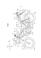
[00019] A Figura 1 é uma vista lateral esquerda que ilustra uma modalidade de uma motocicleta de acordo com a invenção.[00019] Figure 1 is a left side view illustrating an embodiment of a motorcycle according to the invention.
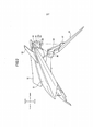
[00020] A Figura 2 é uma vista ampliada que ilustra uma carena- gem traseira, um para-lama traseiro e adjacentes de um dispositivo de luz traseira ilustrado na Figura 1.[00020] Figure 2 is an enlarged view illustrating a rear fairing, a rear fender and adjacent rear light fixture illustrated in Figure 1.
[00021] A Figura 3 é uma vista tomada a partir da traseira do dispositivo de luz traseira, que ilustra a carenagem traseira, o para-lama traseiro e os adjacentes de um dispositivo de luz traseira ilustrado na Figura 1.[00021] Figure 3 is a view taken from the rear of the tail light device, illustrating the rear fairing, rear fender and adjacent ones of a tail light device illustrated in Figure 1.
[00022] A Figura 4 é uma vista lateral ampliada que ilustra o adjacente ao dispositivo de luz traseira ilustrado na Figura 2.[00022] Figure 4 is an enlarged side view illustrating the adjacent to the taillight device illustrated in Figure 2.
[00023] A Figura 5 é uma vista em seção transversal tomada na direção das setas A-A ilustradas na Figura 3.[00023] Figure 5 is a cross-sectional view taken in the direction of arrows A-A illustrated in Figure 3.
[00024] A Figura 6 é uma vista que ilustra o dispositivo de luz traseira, a qual é tomada a partir da traseira.[00024] Figure 6 is a view illustrating the rear light device, which is taken from the rear.
[00025] A Figura 7 é uma vista que ilustra o dispositivo de luz traseira, a qual é tomada a partir da traseira e de baixo.[00025] Figure 7 is a view illustrating the rear light device, which is taken from the rear and below.
[00026] Daqui por diante, é descrita em detalhes uma modalidade da motocicleta, de acordo com a invenção, com referência aos desenhos em anexo. Incidentalmente, presume-se que os desenhos sejam referidos mediante o emprego das direções em vista, conforme designado pelos caracteres de referência, isto é, por meio da colocação das direções em vista para baixo, para cima, direita, esquerda, traseira e dianteira, conforme designado pelos seguintes caracteres de referência Fr, Rr, L, R, U e D, respectivamente, de acordo com as direções vistas por um condutor, na seguinte descrição.[00026] Hereinafter, an embodiment of the motorcycle according to the invention is described in detail with reference to the attached drawings. Incidentally, the drawings are assumed to be referred to by employing the directions in view, as designated by the reference characters, that is, by placing the directions in view down, up, right, left, rear, and front, as designated by the following reference characters Fr, Rr, L, R, U and D, respectively, according to the directions seen by a conductor, in the following description.
[00027] Conforme ilustrado na Figura 1, uma motocicleta 10, de acordo com a presente modalidade, inclui um par de armações principais direita e esquerda 12 que se estendem para trás e para baixo a partir de um tubo frontal 11, um garfo dianteiro 13 suportado de manei- ra rotatória pelo tubo frontal 11, uma roda dianteira WF suportada de maneira giratória na parte de extremidade de fundo do garfo dianteiro 13, um guidão 14 fixado à parte de extremidade de topo do garfo dianteiro 13, um motor 15 montado abaixo da armação principal 12, uma placa de articulação 16 conectada a uma parte de extremidade traseira do armação principal 12, um braço oscilante 17 suportado de maneira oscilante sobre uma placa de articulação 16, uma roda traseira WR suportada de maneira giratória em uma parte de extremidade traseira do braço oscilante 17, uma armação de assento 18 conectado a uma parte traseira superior da armação principal 12 para que se estenda para trás e para cima, uma armação auxiliar traseira 19 conectada à placa de articulação 16 para que se estenda para trás e para cima, cuja parte de extremidade traseira é unida ao armação do assento 18, e uma unidade amortecedora 20 configurada para conectar de maneira balanceada a armação auxiliar traseira 19 e o braço oscilante 17 um ao outro.[00027] As illustrated in Figure 1, a
[00028] Conforme ilustrado nas Figuras 2 e 3, a motocicleta 10 inclui uma carenagem traseira 21 configurada para cobrir uma parte traseira de um corpo do veículo, um dispositivo de luz traseira 50 fornecido em uma parte de extremidade traseira da carenagem traseira 21, um para-lama traseiro 22 configurado para cobrir a roda traseira WR, e uma placa de identificação 23 fornecida sobre o para-lama traseiro 22.[00028] As illustrated in Figures 2 and 3, the
[00029] Incidentalmente, na Figura 1, o numeral de referência 24 indica um para-brisa, o numeral de referência 25 denota um farol dianteiro, o numeral de referência 26 representa uma carenagem dianteira, o numeral de referência 27 indica uma carenagem lateral dianteira, o numeral de referência 28 denota uma carenagem lateral, o numeral de referência 29 representa um tanque de combustível, o numeral de referência 30 indica um assento do condutor, o numeral de referência 31 denota um assento do passageiro, o numeral de referência 32 repre- senta uma barra de apoio, o numeral de referência 33 indica um paralama dianteiro, o numeral de referência 34 denota um cano de descarga, o numeral de referência 35 representa um silencioso, o numeral de referência 36 indica um pisca-pisca traseiro, o numeral de referência 37 representa um refletor, o numeral de referência 38 indica um estribo principal e o numeral de referência 39 denota um estribo de passageiro.[00029] Incidentally, in Figure 1,
[00030] Conforme ilustrado nas Figuras 4 a 7, o dispositivo de luz traseira 50 inclui principalmente um invólucro 51 fixo a um lado do veículo, uma lente principal 52 cuja abertura dianteira é obstruída pelo invólucro 51, um dispositivo de iluminação (fonte de luz) 53 fixado ao invólucro 51, uma parte côncava 54 formada sobre a superfície de fundo da lente principal 52 a fim de que seja regredida para cima na mesma, uma porta de irradiação de placa de identificação 55 formada na superfície de topo da parte côncava 54 para que conduza a luz a partir do dispositivo de iluminação 53 para a placa de identificação 23, e a lente de irradiação da placa de identificação 56 montada na porta de irradiação de placa de identificação 55.[00030] As illustrated in Figures 4 to 7, the
[00031] Conforme ilustrado na Figura 5, o dispositivo de iluminação 53 inclui um soquete 53a encaixado no invólucro 51, um conector 53b configurado para se estender para frente a partir do soquete 53a e para que seja conectado eletricamente a uma unidade de controle de dispositivo de iluminação (não mostrada) montada no veículo, e uma lâmpada elétrica de parada 53c fixada ao soquete 53a. Incidentemente, as linhas tracejadas curtas e longas alternadas ilustradas nas Figuras 2 e 3 representam os raios de luz de iluminação da lâmpada elétrica de parada 53c.[00031] As illustrated in Figure 5, the
[00032] De acordo com a presente modalidade, conforme ilustrado nas Figuras 4 e 6, a lente de irradiação da placa de identificação 56 é formada em um formato, em vista traseira da mesma, a qual coincide substancialmente com o formato de uma superfície de arco circular 57 da parte de borda de fundo da superfície traseira da lente principal 52 e é disposta a fim de que seja acomodada em uma região X da superfície de arco circular 57.[00032] In accordance with the present embodiment, as illustrated in Figures 4 and 6, the radiating lens of the
[00033] De acordo com a presente modalidade, uma parede dianteira 54a da parte côncava 54 é formada para que seja inclinada para trás e para cima, conforme ilustrado na Figura 4. A parte côncava 54 é formada de modo que uma parte dianteira da mesma seja mais retrocedida para cima do que uma parte traseira da mesma, conforme visto na Figura 4. Incidentalmente, uma parte hachurada por linhas tracejadas curtas e longas alternadas, ilustradas na Figura 4 e Figura 5, representa a extensão da parte côncava 54.[00033] In accordance with the present embodiment, a
[00034] De acordo com a presente modalidade, conforme ilustrado nas Figuras 4 e 5, uma borda de extremidade dianteira 54b da parte côncava 54 é disposta nas proximidades de uma borda de abertura 21a da carenagem traseira 21.[00034] According to the present embodiment, as illustrated in Figures 4 and 5, a
[00035] De acordo com a presente modalidade, conforme ilustrado na Figura 5, um refletor 58 é formado sobre a superfície interna do invólucro 51 do dispositivo de luz traseira 50. Uma parte dobrada para trás 58a em uma parte inferior do refletor 58 é disposta para que seja sobreposta nas proximidades da parte de extremidade dianteira da porta de irradiação de placa de identificação 55 em uma direção de cima para baixo.[00035] In accordance with the present embodiment, as illustrated in Figure 5, a
[00036] De acordo com a presente modalidade, conforme ilustrado nas Figuras 5 a 7, a lente de irradiação da placa de identificação 56 é formada por uma placa transparente de resina sintética para ter um formato uniformemente curvilíneo em seção transversal por meio da formação de uma pluralidade de superfícies curvadas a fim de que sejam contínuas umas às outras. Incidentalmente, a lente de irradiação da placa de identificação 56 pode ser formada em um formato multifa- cetado por meio da formação de uma pluralidade de superfície planas, das quais cada uma forma uma pluralidade de ângulos com algumas adjacentes da pluralidades de superfícies planas, respectivamente.[00036] In accordance with the present embodiment, as illustrated in Figures 5 to 7, the
[00037] De acordo com a presente modalidade, conforme ilustrado nas Figuras 3 e 6, a lente principal 52 tem um formato formado para se assemelhar ao formato de um silencioso e é formada em um formato cilindrico de modo que a superfície de fundo da lente principal 52 se destaca para fora em direção à traseira, conforme comparado à care- nagem traseira 21. Incidentalmente, o formato formado para se assemelhar ao formato do silencioso é de tal modo que o formato da circunferência externa da lente principal 52 se assemelha ao formato externo do silencioso, e o formato de um objeto circular 52a fornecido sobre o centro de uma superfície traseira da lente principal 52 se assemelha ao formato de uma porta de saída do silencioso.[00037] In accordance with the present embodiment, as illustrated in Figures 3 and 6, the
[00038] Conforme descrito acima, de acordo com a motocicleta 10 da presente modalidade, o dispositivo de luz traseira 50 é configurado de modo que a lente principal 52 seja fornecida com a porta de irradiação de placa de identificação 55 configurada para conduzir a luz a partir do dispositivo de iluminação 53 para a placa de identificação 23 e com a lente de irradiação da placa de identificação 56 disposta na porta de irradiação da placa de identificação 55, e que a parte côncava 54 que constitui a porta de irradiação de placa de identificação 55 seja formada na superfície de fundo da lente principal 52, a fim de que seja retrocedida na mesma para cima e de modo que a parede dianteira 54a seja inclinada em direção à traseira e para cima. Deste modo, a lente de irradiação da placa de identificação 56 é disposta no lado interno da parte côncava 54. Consequentemente, pode-se evitar que a luz que passa através da lente de irradiação da placa de identificação 56 seja vista a partir da traseira do veículo, sem o fornecimento da cobertura do corpo do veículo sobre uma parte inferior do dispositivo de luz traseira 50. Além disso, devido ao fato de que a parede dianteira 54a da parte côncava 54 é inclinada em direção à traseira e para cima, a faixa de irradiação de luz a partir da lente de irradiação da placa de identificação 56 pode ser expandida para frente. Consequentemente, a placa de identificação 23 pode ser disposta em uma posição dianteira. Deste modo, a parte de extremidade traseira do para-lama traseiro 22 pode ser disposta em um local dianteiro.[00038] As described above, according to the
[00039] De acordo com a motocicleta 10 da presente modalidade, a lente de irradiação da placa de identificação 56 é formada em um formato, em vista traseira da mesma, a qual coincide substancialmente com o formato de uma superfície de arco circular 57 da parte de borda de fundo da superfície traseira da lente principal 52 e é disposta a fim de que seja acomodada em uma região X da superfície de arco circular 57. Deste modo, pode-se evitar que a lente de irradiação da placa de identificação 56 seja vista através da superfície traseira da lente principal 52. Além disso, a luz irradiada pode ser iluminada com um projetor na direção lateral do veículo, ao longo da direção do arco circular. Consequentemente, a faixa de irradiação de luz pode ser expandida em uma direção da largura. Consequentemente, a placa de identificação 23 pode ser irradiada de maneira eficaz.[00039] According to the
[00040] De acordo com a motocicleta 10 da presente modalidade, a borda de extremidade dianteira 54b da parte côncava 54 é disposta nas proximidades da borda de abertura 21a da carenagem traseira 21. Deste modo, a borda de extremidade dianteira 54a da parte côncava 54 coincide substancialmente com a borda de abertura 21a da carena- gem traseira 21, em vista traseira do veículo. Consequentemente, a borda de extremidade dianteira 54b da parte côncava 54 pode ficar obscura. Consequentemente, a aparência da motocicleta 10 pode ser aperfeiçoada.[00040] According to the
[00041] De acordo com a motocicleta 10 da presente modalidade, a parte dobrada para trás 58a do refletor 58 do dispositivo de luz traseira 50 é disposta a fim de que seja sobreposta nas proximidades da parte de extremidade dianteira da porta de irradiação de placa de identificação 55. Deste modo, nenhuma luz é transmitida para frente a partir da parte de extremidade dianteira da porta de irradiação de placa de identificação 55. Consequentemente, pode-se evitar que a borda de extremidade dianteira 54b da parte côncava 54 seja claramente vista devido à refração da luz transmitida na borda de extremidade dianteira 54b da parte côncava 54. Consequentemente, a aparência da motocicleta 10 pode ser aperfeiçoada.[00041] According to the
[00042] De acordo com a motocicleta 10 da presente modalidade, a lente de irradiação da placa de identificação 56 é formada em um formato multifacetado ou um formato de superfície curvada. Deste modo, a lente de irradiação da placa de identificação 56 pode ser formada por meio da conformação de acordo com o formato do dispositivo de luz traseira 50. Consequentemente, o grau de flexibilidade no projeto do dispositivo de luz traseira 50 pode ser otimizado.[00042] According to the
[00043] De acordo com a motocicleta 10 da presente modalidade, a lente principal 52 tem um formato formado para se assemelhar ao formato de um silencioso e é formada substancialmente semelhante ao cilindro de modo que a superfície de fundo da lente principal 52 se destaca para fora em direção à traseira além da carenagem traseira 21. Deste modo, a aparência esportiva do dispositivo de luz traseira pode ser obtida mediante a formação da lente principal 52 para que tenha um formato formado para se assemelhar ao formato de um silencioso. Além disso, a parte côncava 54 pode ser facilmente formada na lente principal 52.[00043] According to the
[00044] Embora a invenção tenha sido descrita em detalhes com referência às modalidades específicas da mesma, é evidente para os versados na técnica que diversas mudanças e modificações podem ser feitas sem que se desvie do espírito e escopo das reivindicações.[00044] While the invention has been described in detail with reference to specific embodiments thereof, it is apparent to those skilled in the art that various changes and modifications may be made without departing from the spirit and scope of the claims.
[00045] Este pedido é baseado no pedido de patente japonesa (pedi- do de patente no 2007-340097) depositado em 28 de dezembro de 2007, cujo conteúdo integral está aqui incorporado a título de referência. Aplicabilidade Industrial[00045] This application is based on the Japanese patent application (Patent Application No. 2007-340097) filed December 28, 2007, the entire contents of which are incorporated herein by reference. Industrial Applicability
[00046] A invenção pode ser aplicada a uma motocicleta que tem um dispositivo de luz traseira e uma placa de identificação. Listagem de Referência 10 motocicletaWF roda dianteiraWR roda traseira21 carenagem traseira21a borda de abertura22 para-lama traseiro23 placa de identificação50 dispositivo de luz traseira51 invólucro52 lente principal53 dispositivo de iluminação (fonte de luz)53a soquete53b conector53c lâmpada elétrica de parada 54 parte côncava54a parede dianteira54b borda de extremidade dianteira 55 porta de irradiação de placa de identificação56 lente de irradiação da placa de identificação57 superfície de arco circular (formato de arco circular) 58 refletor58a parte dobrada para trásX uma região da superfície de arco circular[00046] The invention can be applied to a motorcycle that has a taillight device and a nameplate.
Claims (5)
Applications Claiming Priority (3)
| Application Number | Priority Date | Filing Date | Title |
|---|---|---|---|
| JP2007340097A JP5163869B2 (en) | 2007-12-28 | 2007-12-28 | Motorcycle |
| JP2007-340097 | 2007-12-28 | ||
| PCT/JP2008/067042 WO2009084289A1 (en) | 2007-12-28 | 2008-09-19 | Two-wheeled motor vehicle |
Publications (2)
| Publication Number | Publication Date |
|---|---|
| BRPI0818475A2 BRPI0818475A2 (en) | 2021-06-01 |
| BRPI0818475B1 true BRPI0818475B1 (en) | 2021-11-30 |
Family
ID=40824017
Family Applications (1)
| Application Number | Title | Priority Date | Filing Date |
|---|---|---|---|
| BRPI0818475-5A BRPI0818475B1 (en) | 2007-12-28 | 2008-09-19 | MOTORCYCLE |
Country Status (6)
| Country | Link |
|---|---|
| EP (1) | EP2192031B1 (en) |
| JP (1) | JP5163869B2 (en) |
| CN (1) | CN101687526B (en) |
| BR (1) | BRPI0818475B1 (en) |
| ES (1) | ES2492473T3 (en) |
| WO (1) | WO2009084289A1 (en) |
Families Citing this family (9)
| Publication number | Priority date | Publication date | Assignee | Title |
|---|---|---|---|---|
| TWI441747B (en) * | 2010-06-17 | 2014-06-21 | Kwang Yang Motor Co | Locomotive rear light construction |
| JP5460511B2 (en) * | 2010-07-23 | 2014-04-02 | 本田技研工業株式会社 | Rear fender for vehicles |
| CN101885355A (en) * | 2010-08-05 | 2010-11-17 | 力帆实业(集团)股份有限公司 | Irradiation equipment of rear license plate of motorcycle |
| JP5840846B2 (en) * | 2011-02-25 | 2016-01-06 | 本田技研工業株式会社 | Storage structure for power connection for saddle riding type vehicles |
| CN103029775B (en) * | 2011-09-28 | 2016-08-03 | 光阳工业股份有限公司 | The Rear splash guard component of motorcycle |
| JP2013136307A (en) | 2011-12-28 | 2013-07-11 | Yamaha Motor Co Ltd | Saddle-ride type vehicle |
| JP6532674B2 (en) * | 2014-12-26 | 2019-06-19 | 川崎重工業株式会社 | Straddle type vehicle |
| JP7377142B2 (en) | 2020-03-17 | 2023-11-09 | 本田技研工業株式会社 | saddle type vehicle |
| JP7061638B2 (en) * | 2020-03-27 | 2022-04-28 | 本田技研工業株式会社 | Saddle-type vehicle |
Family Cites Families (8)
| Publication number | Priority date | Publication date | Assignee | Title |
|---|---|---|---|---|
| JPS5790504U (en) * | 1980-11-26 | 1982-06-03 | ||
| JPS63159390U (en) * | 1987-04-07 | 1988-10-19 | ||
| JP3165039B2 (en) * | 1996-07-26 | 2001-05-14 | 株式会社小糸製作所 | Lighting for motorcycles |
| JPH10166937A (en) | 1996-12-09 | 1998-06-23 | Yamaha Motor Co Ltd | Tail lamp structure for motorcycle |
| JP2002087350A (en) * | 2000-07-14 | 2002-03-27 | Yamaha Motor Co Ltd | Cover structure in periphery of tail lamp for motorcycle, and tail lamp for motorcycle |
| KR100539600B1 (en) * | 2001-10-24 | 2005-12-28 | 혼다 기켄 고교 가부시키가이샤 | Rear combination lamp of motorcycle |
| JP2007030526A (en) * | 2003-07-04 | 2007-02-08 | Yamaha Motor Co Ltd | Motorcycle |
| JP4535331B2 (en) * | 2005-11-10 | 2010-09-01 | 本田技研工業株式会社 | Tail lamp structure |
-
2007
- 2007-12-28 JP JP2007340097A patent/JP5163869B2/en not_active Expired - Fee Related
-
2008
- 2008-09-19 ES ES08866512.0T patent/ES2492473T3/en active Active
- 2008-09-19 WO PCT/JP2008/067042 patent/WO2009084289A1/en active Application Filing
- 2008-09-19 CN CN200880023921.2A patent/CN101687526B/en active Active
- 2008-09-19 BR BRPI0818475-5A patent/BRPI0818475B1/en active IP Right Grant
- 2008-09-19 EP EP08866512.0A patent/EP2192031B1/en not_active Not-in-force
Also Published As
| Publication number | Publication date |
|---|---|
| JP2009160973A (en) | 2009-07-23 |
| EP2192031A4 (en) | 2012-09-26 |
| CN101687526A (en) | 2010-03-31 |
| BRPI0818475A2 (en) | 2021-06-01 |
| EP2192031A1 (en) | 2010-06-02 |
| EP2192031B1 (en) | 2014-08-06 |
| WO2009084289A1 (en) | 2009-07-09 |
| CN101687526B (en) | 2014-05-07 |
| ES2492473T3 (en) | 2014-09-09 |
| JP5163869B2 (en) | 2013-03-13 |
Similar Documents
| Publication | Publication Date | Title |
|---|---|---|
| BRPI0818475B1 (en) | MOTORCYCLE | |
| ES2313568T3 (en) | TAIL LAMP STRUCTURE. | |
| US7559679B2 (en) | Vehicle light apparatus and motorcycle having the light apparatus | |
| TWI389811B (en) | Locomotive position lights and lighting fixtures | |
| ES2351672T3 (en) | FLASHING AND VEHICLE OF THE TYPE TO BE ASSEMBLED TO HORCAJADAS. | |
| TW470714B (en) | Headlight of motorcycle | |
| ES2564967T3 (en) | Straddle Type Vehicle | |
| JP5719884B2 (en) | Vehicle lamp | |
| CN104019417B (en) | Two-wheeled front lamp device | |
| BRPI0704660B1 (en) | MOUNTED TRAVEL VEHICLE | |
| JP5301295B2 (en) | Vehicle taillight device | |
| CN102287735B (en) | Fixture and automotive tumbrel | |
| CN103448844A (en) | Saddle riding type vehicle | |
| JP2011111029A (en) | Front part lamp structure of saddle riding type vehicle | |
| BRPI0805677B1 (en) | vehicular lighting device structure | |
| EP2151351A1 (en) | Lamp device-integrated rearview mirror | |
| BRPI0803846B1 (en) | "RIDING TYPE VEHICLES" | |
| JP3996001B2 (en) | Vehicle signal lights | |
| ES2359153T3 (en) | STEERING INTERMITTENT ASSEMBLY STRUCTURE. | |
| JP5504016B2 (en) | Headlight device | |
| TWI652194B (en) | Straddle type vehicle | |
| BR112021011233A2 (en) | Mounting Vehicle Lighting Device | |
| CN109305263B (en) | Saddle-ride type vehicle | |
| JP7090220B2 (en) | Bicycle headlights | |
| BR102021021192A2 (en) | LIGHTING DEVICE STRUCTURE |
Legal Events
| Date | Code | Title | Description |
|---|---|---|---|
| B06F | Objections, documents and/or translations needed after an examination request according [chapter 6.6 patent gazette] | ||
| B06U | Preliminary requirement: requests with searches performed by other patent offices: procedure suspended [chapter 6.21 patent gazette] | ||
| B09A | Decision: intention to grant [chapter 9.1 patent gazette] | ||
| B16A | Patent or certificate of addition of invention granted [chapter 16.1 patent gazette] |
Free format text: PRAZO DE VALIDADE: 20 (VINTE) ANOS CONTADOS A PARTIR DE 19/09/2008, OBSERVADAS AS CONDICOES LEGAIS. PATENTE CONCEDIDA CONFORME ADI 5.529/DF, QUE DETERMINA A ALTERACAO DO PRAZO DE CONCESSAO. |