BR112018008552B1 - CONTINUOUS CASTING APPARATUS AND CONTINUOUS MULTILAYER PLATE CASTING METHOD - Google Patents
CONTINUOUS CASTING APPARATUS AND CONTINUOUS MULTILAYER PLATE CASTING METHOD Download PDFInfo
- Publication number
- BR112018008552B1 BR112018008552B1 BR112018008552-9A BR112018008552A BR112018008552B1 BR 112018008552 B1 BR112018008552 B1 BR 112018008552B1 BR 112018008552 A BR112018008552 A BR 112018008552A BR 112018008552 B1 BR112018008552 B1 BR 112018008552B1
- Authority
- BR
- Brazil
- Prior art keywords
- molten steel
- distributor
- nozzle
- holding portion
- casting mold
- Prior art date
Links
- 238000005266 casting Methods 0.000 title claims abstract description 103
- 238000009749 continuous casting Methods 0.000 title claims abstract description 52
- 238000000034 method Methods 0.000 title claims abstract description 39
- 229910000831 Steel Inorganic materials 0.000 claims abstract description 279
- 239000010959 steel Substances 0.000 claims abstract description 279
- 238000007654 immersion Methods 0.000 claims abstract description 82
- 230000007246 mechanism Effects 0.000 claims abstract description 5
- 238000004891 communication Methods 0.000 claims description 32
- 230000014509 gene expression Effects 0.000 claims description 26
- 238000003756 stirring Methods 0.000 claims description 19
- 229910001208 Crucible steel Inorganic materials 0.000 abstract description 61
- 238000004519 manufacturing process Methods 0.000 abstract description 17
- 239000002344 surface layer Substances 0.000 description 55
- 238000000926 separation method Methods 0.000 description 34
- 239000010410 layer Substances 0.000 description 25
- 230000014759 maintenance of location Effects 0.000 description 20
- 230000004907 flux Effects 0.000 description 18
- 241000277275 Oncorhynchus mykiss Species 0.000 description 16
- 238000002156 mixing Methods 0.000 description 13
- 239000000203 mixture Substances 0.000 description 11
- 101150006573 PAN1 gene Proteins 0.000 description 10
- XEEYBQQBJWHFJM-UHFFFAOYSA-N Iron Chemical compound [Fe] XEEYBQQBJWHFJM-UHFFFAOYSA-N 0.000 description 8
- 239000011324 bead Substances 0.000 description 7
- 238000009826 distribution Methods 0.000 description 7
- 239000000843 powder Substances 0.000 description 7
- 230000015556 catabolic process Effects 0.000 description 6
- 238000006731 degradation reaction Methods 0.000 description 6
- 230000005499 meniscus Effects 0.000 description 6
- 238000007711 solidification Methods 0.000 description 6
- 230000008023 solidification Effects 0.000 description 6
- 238000010586 diagram Methods 0.000 description 5
- 229910052751 metal Inorganic materials 0.000 description 5
- 239000002184 metal Substances 0.000 description 5
- 230000004048 modification Effects 0.000 description 5
- 238000012986 modification Methods 0.000 description 5
- 238000005275 alloying Methods 0.000 description 4
- 230000003247 decreasing effect Effects 0.000 description 4
- 230000002349 favourable effect Effects 0.000 description 4
- 229910052742 iron Inorganic materials 0.000 description 4
- 238000002407 reforming Methods 0.000 description 4
- 230000000717 retained effect Effects 0.000 description 4
- 238000013019 agitation Methods 0.000 description 3
- 229910045601 alloy Inorganic materials 0.000 description 3
- 239000000956 alloy Substances 0.000 description 3
- 238000004458 analytical method Methods 0.000 description 3
- 229910052799 carbon Inorganic materials 0.000 description 3
- 230000001276 controlling effect Effects 0.000 description 3
- 230000000694 effects Effects 0.000 description 3
- 238000010438 heat treatment Methods 0.000 description 3
- 238000002844 melting Methods 0.000 description 3
- 230000008018 melting Effects 0.000 description 3
- 230000001105 regulatory effect Effects 0.000 description 3
- 230000015572 biosynthetic process Effects 0.000 description 2
- 150000002739 metals Chemical class 0.000 description 2
- 229910052759 nickel Inorganic materials 0.000 description 2
- 238000012360 testing method Methods 0.000 description 2
- OKTJSMMVPCPJKN-UHFFFAOYSA-N Carbon Chemical compound [C] OKTJSMMVPCPJKN-UHFFFAOYSA-N 0.000 description 1
- 229910001209 Low-carbon steel Inorganic materials 0.000 description 1
- 230000009471 action Effects 0.000 description 1
- 239000000654 additive Substances 0.000 description 1
- 230000000996 additive effect Effects 0.000 description 1
- 229910052782 aluminium Inorganic materials 0.000 description 1
- 229910052796 boron Inorganic materials 0.000 description 1
- 230000005587 bubbling Effects 0.000 description 1
- 239000000470 constituent Substances 0.000 description 1
- 238000001816 cooling Methods 0.000 description 1
- 229910052802 copper Inorganic materials 0.000 description 1
- 238000006477 desulfuration reaction Methods 0.000 description 1
- 230000023556 desulfurization Effects 0.000 description 1
- 238000004453 electron probe microanalysis Methods 0.000 description 1
- 238000002474 experimental method Methods 0.000 description 1
- 230000006698 induction Effects 0.000 description 1
- 230000003993 interaction Effects 0.000 description 1
- 229910052748 manganese Inorganic materials 0.000 description 1
- 229910052750 molybdenum Inorganic materials 0.000 description 1
- 229910052758 niobium Inorganic materials 0.000 description 1
- 229910052698 phosphorus Inorganic materials 0.000 description 1
- 230000008569 process Effects 0.000 description 1
- 229910052761 rare earth metal Inorganic materials 0.000 description 1
- 238000007670 refining Methods 0.000 description 1
- 229910052710 silicon Inorganic materials 0.000 description 1
- 238000006467 substitution reaction Methods 0.000 description 1
- 229910052717 sulfur Inorganic materials 0.000 description 1
- 230000001629 suppression Effects 0.000 description 1
- 229910052719 titanium Inorganic materials 0.000 description 1
- 238000005303 weighing Methods 0.000 description 1
- 238000004804 winding Methods 0.000 description 1
Images


Classifications
-
- B—PERFORMING OPERATIONS; TRANSPORTING
- B22—CASTING; POWDER METALLURGY
- B22D—CASTING OF METALS; CASTING OF OTHER SUBSTANCES BY THE SAME PROCESSES OR DEVICES
- B22D11/00—Continuous casting of metals, i.e. casting in indefinite lengths
- B22D11/10—Supplying or treating molten metal
- B22D11/108—Feeding additives, powders, or the like
-
- B—PERFORMING OPERATIONS; TRANSPORTING
- B22—CASTING; POWDER METALLURGY
- B22D—CASTING OF METALS; CASTING OF OTHER SUBSTANCES BY THE SAME PROCESSES OR DEVICES
- B22D11/00—Continuous casting of metals, i.e. casting in indefinite lengths
- B22D11/007—Continuous casting of metals, i.e. casting in indefinite lengths of composite ingots, i.e. two or more molten metals of different compositions being used to integrally cast the ingots
-
- B—PERFORMING OPERATIONS; TRANSPORTING
- B22—CASTING; POWDER METALLURGY
- B22D—CASTING OF METALS; CASTING OF OTHER SUBSTANCES BY THE SAME PROCESSES OR DEVICES
- B22D11/00—Continuous casting of metals, i.e. casting in indefinite lengths
- B22D11/04—Continuous casting of metals, i.e. casting in indefinite lengths into open-ended moulds
-
- B—PERFORMING OPERATIONS; TRANSPORTING
- B22—CASTING; POWDER METALLURGY
- B22D—CASTING OF METALS; CASTING OF OTHER SUBSTANCES BY THE SAME PROCESSES OR DEVICES
- B22D11/00—Continuous casting of metals, i.e. casting in indefinite lengths
- B22D11/10—Supplying or treating molten metal
- B22D11/103—Distributing the molten metal, e.g. using runners, floats, distributors
-
- B—PERFORMING OPERATIONS; TRANSPORTING
- B22—CASTING; POWDER METALLURGY
- B22D—CASTING OF METALS; CASTING OF OTHER SUBSTANCES BY THE SAME PROCESSES OR DEVICES
- B22D11/00—Continuous casting of metals, i.e. casting in indefinite lengths
- B22D11/10—Supplying or treating molten metal
- B22D11/11—Treating the molten metal
- B22D11/114—Treating the molten metal by using agitating or vibrating means
- B22D11/115—Treating the molten metal by using agitating or vibrating means by using magnetic fields
-
- B—PERFORMING OPERATIONS; TRANSPORTING
- B22—CASTING; POWDER METALLURGY
- B22D—CASTING OF METALS; CASTING OF OTHER SUBSTANCES BY THE SAME PROCESSES OR DEVICES
- B22D11/00—Continuous casting of metals, i.e. casting in indefinite lengths
- B22D11/16—Controlling or regulating processes or operations
Landscapes
- Engineering & Computer Science (AREA)
- Mechanical Engineering (AREA)
- Continuous Casting (AREA)
Abstract
aparelho de fundição contínua e método de fundição contínua de placa multicamada. a presente invenção refere-se a um dispositivo de fabricação contínua de uma placa multicamada, sendo que o dito dispositivo é equipado com: uma panela que tem um bocal de fornecimento de aço fundido; um distribuidor que tem uma primeira unidade de retenção que recebe um fornecimento de aço fundido a partir da panela, e que tem um primeiro bocal de imersão e uma segunda unidade de retenção que está em posição adjacente à primeira unidade de retenção, com uma trajetória de fluxo interposta entre as mesmas, e que tem um segundo bocal de imersão; um mecanismo de adição que adiciona um elemento prescrito ao aço fundido na segunda unidade de retenção; e um molde de fundição que recebe o fornecimento do aço fundido a partir do distribuidor.continuous casting apparatus and multilayer plate continuous casting method. the present invention relates to a device for the continuous manufacture of a multilayer plate, said device being equipped with: a pan having a molten steel supply nozzle; a dispenser having a first holding unit which receives a supply of molten steel from the ladle, and having a first immersion nozzle and a second holding unit which is adjacent to the first holding unit, with a path of flow interposed therebetween, and which has a second immersion nozzle; an addition mechanism that adds a prescribed element to the cast steel in the second holding unit; and a casting mold that receives the supply of molten steel from the distributor.
Description
[001] A presente invenção refere-se a um aparelho de lingotamento contínuo e um método de lingotamento contínuo de uma placa multicamada.[001] The present invention relates to a continuous casting apparatus and a method of continuous casting of a multilayer slab.
[002] A prioridade é reivindicada com base no Pedido de Patente Japonês n° 2015-213678 depositado no Japão em 30 de outubro de 2015, cujo conteúdo está incorporado a título de referência no presente documento.[002] Priority is claimed based on Japanese Patent Application No. 2015-213678 filed in Japan on October 30, 2015, the contents of which are incorporated by reference herein.
[003] Até agora, foram feitas tentativas para fabricar placas em formato de múltiplas camadas tendo composições mutuamente diferentes na camada superficial e na camada interna. Por exemplo, o Documento de Patente 1 revela um método em que dois bocais de imersão que têm comprimentos diferentes são inseridos em um reservatório de metal fundido em um molde de fundição de modo que os locais de profundidade de furos de descarga dos bocais de imersão se difiram um do outro, um campo magnético de corrente contínua é aplicado entre diferentes tipos de metais fundidos para impedir a mistura dos metais fundidos, e uma placa multicamada é fabricada.[003] So far, attempts have been made to manufacture boards in a multi-layer format having mutually different compositions in the surface layer and the inner layer. For example,
[004] No entanto, no método revelado pelo Documento de Patente 1, dois tipos de aços fundidos que têm composições diferentes são usados e, dessa forma, é necessário produzir separadamente esses dois tipos de aços fundidos ao mesmo tempo fundindo e transportar os aços fundidos para um processo de fundição contínua. Além disso, como recipientes de retenção intermediários para os respectivos aços fundidos, é necessário preparar funis (ou seja, dois funis se tornam necessários para reter separadamente dois tipos de aços fundidos). Além disso, as taxas de fluxo de despejamento se diferem significativamente entre o aço fundido para uma camada superficial e o aço fundido para uma camada interna e, dessa forma, as quantidades de aços fundidos necessários para cada aquecimento se diferem significativamente. Por esses motivos, tem sido difícil realizar o método revelado pelo Documento de Patente 1 em siderúrgicas convencionais.[004] However, in the method revealed by
[005] Portanto, como métodos de fundição de placas de forma mais conveniente que têm composições mutuamente diferentes na camada superficial e na camada interna, principalmente, dois métodos estão sendo estudados. Como o primeiro método, estudos estão em andamento em relação a um método de reforma de uma camada superficial de placa fornecendo continuamente um fio ou pó para lingotamento contínuo à qual um elemento predeterminado é adicionado ao lado superior de uma banda de campo magnético de corrente contínua usando frenagem eletromagnética que pode ser obtida pela aplicação de um campo magnético de corrente contínua que tem uma distribuição de densidade de fluxo magnético uniforme ao longo da direção da espessura de um molde de fundição na direção da espessura do molde de fundição.[005] Therefore, as methods of casting slabs more conveniently that have mutually different compositions in the surface layer and the inner layer, mainly, two methods are being studied. As the first method, studies are underway regarding a method of reforming a surface layer of slab by continuously supplying a wire or powder for continuous casting to which a predetermined element is added to the upper side of a band of direct current magnetic field. using electromagnetic braking which can be achieved by applying a direct current magnetic field that has a uniform magnetic flux density distribution along the direction of the thickness of a casting mold in the direction of the thickness of the casting mold.
[006] Exemplos de documentos que revelam um método para adicionar um elemento ao aço fundido em um molde de fundição usando um fio ou similares incluem o Documento de Patente 2. No método revelado pelo Documento de Patente 2, um campo magnético de corrente contínua que bloqueia o aço fundido em um molde de fundição é formado em um local pelo menos 200 mm abaixo do menisco do aço fundido formado no molde de fundição, um elemento predeterminado é adicionado ao aço fundido na porção superior ou o aço fundido na porção inferior, e o aço fundido no molde de fundição é agitado.[006] Examples of documents that disclose a method for adding an element to molten steel in a casting mold using wire or the like include
[007] Exemplos de um método de fornecimento contínuo de pó para lingotamento contínuo ao qual um elemento predeterminado é adicionado ou um método de adicionar um elemento ao aço fundido fornecendo continuamente pó de metal ou grãos de metal que não reagem facilmente com o pó do lado superior de uma camada de pó incluem o método revelado pelo Documento de Patente 3. No método revelado pelo Documento de Patente 3, o pó para lingotamento contínuo ao qual elementos de liga são adicionados é continuamente fornecido, e um fluxo de agitação que dissolve e mistura os elementos de liga em um corte transversal horizontal de aço fundido de porção superior em um molde de lingotamento contínuo é formado usando um dispositivo de agitação eletromagnética instalado na porção superior do molde de fundição. Além disso, no método descrito acima, uma banda de campo magnético de corrente contínua é formada no lado inferior do dispositivo de agitação eletromagnético pela aplicação de um campo magnético de corrente contínua na direção da espessura de uma placa, e o aço fundido é fornecido a partir de um bocal de imersão a um local abaixo da faixa do campo magnético de corrente contínua e fundido. No Documento de Patente 3, uma placa em formato de múltiplas camadas, em que a concentração dos elementos de liga na área da camada superficial de placa é maior do que na camada interna, é fabricada usando um método como descrito acima.[007] Examples of a method of continuously supplying powder to continuous casting to which a predetermined element is added or a method of adding an element to molten steel by continuously supplying metal powder or metal grains that do not react easily with the powder on the side top of a layer of powder include the method disclosed by
[008] Entretanto, no molde de fundição, uma camada de pó está presente na porção superior, e o molde de fundição tem um corte transversal retangular e é resfriado a partir da periferia. Portanto, não é possível agitar suficientemente o aço fundido no molde de fundição, e é difícil tornar a concentração uniforme. Além disso, as quantidades de aço fundido fornecido à porção superior e à porção inferior de um cordão não são controladas independentemente e, dessa forma, houve um problema em que a mistura de aços fundidos entre os reservatórios superior e inferior não pode ser evitada, e é difícil fabricar placas com um alto grau de separação.[008] However, in the casting mold, a layer of powder is present in the upper portion, and the casting mold has a rectangular cross-section and is cooled from the periphery. Therefore, it is not possible to sufficiently agitate the molten steel in the casting mold, and it is difficult to make the concentration uniform. In addition, the amounts of molten steel supplied to the upper and lower portions of a bead are not independently controlled and thus there has been a problem where mixing of molten steels between the upper and lower reservoirs cannot be avoided, and it is difficult to manufacture boards with a high degree of separation.
[009] Como um método para reformar uma superfície de placa após a fundição, por exemplo, o Documento de Patente 4 revela um método de reforma de camada superficial de uma placa em que a camada superficial de uma placa é fundida por pelo menos um dentre aquecimento por indução ou aquecimento de plasma e um elemento aditivo ou uma liga do mesmo é adicionado à área de camada superficial da placa derretida. Entretanto, neste método, a adição do elemento de liga é possível, porém o volume de um reservatório de fusão é pequeno e, dessa forma, é difícil tornar a concentração uniforme. Além disso, neste método, houve um problema pelo fato de que é difícil derreter a placa inteira de uma vez, e é necessário realizar a fusão e reforma várias vezes para reformar toda a circunferência da camada superficial de placa.[009] As a method for reforming a surface of a plate after casting, for example,
[0010] Documento de Patente 1: Pedido de Patente Não- examinado Japonês, Primeira Publicação n° S63-108947[0010] Patent Document 1: Japanese Unexamined Patent Application, First Publication No. S63-108947
[0011] Documento de Patente 2: Pedido de Patente Não- examinado Japonês, Primeira Publicação n° H3-243245[0011] Patent Document 2: Japanese Unexamined Patent Application, First Publication No. H3-243245
[0012] Documento de Patente 3: Pedido de Patente Não- examinado Japonês, Primeira Publicação n° H8-290236[0012] Patent Document 3: Japanese Unexamined Patent Application, First Publication No. H8-290236
[0013] Documento de Patente 4: Pedido de Patente Não- examinado Japonês, Primeira Publicação n° 2004-195512[0013] Patent Document 4: Japanese Unexamined Patent Application, First Publication No. 2004-195512
[0014] A presente invenção foi realizada em consideração das circunstâncias descritas acima, e um objetivo da presente invenção é proporcionar um aparelho de lingotamento contínuo e um método de lingotamento contínuo para uma placa multicamada com capacidade de suprimir a degradação da qualidade de uma placa multicamada durante a fabricação da placa multicamada usando uma panela e um distribuidor.[0014] The present invention has been carried out in consideration of the circumstances described above, and an object of the present invention is to provide a continuous casting apparatus and a continuous casting method for a multilayer slab capable of suppressing the quality degradation of a multilayer slab. during the fabrication of the multilayer board using a pan and a dispenser.
[0015] Para atingir o objetivo descrito acima, a presente invenção emprega os seguintes.[0015] To achieve the objective described above, the present invention employs the following.
[0016] (1) Um aparelho de lingotamento contínuo para uma placa multicamada de acordo com um aspecto da presente invenção inclui uma panela que tem um bocal de fornecimento de aço fundido; um distribuidor que tem uma primeira porção de retenção que recebe o fornecimento de aço fundido da panela através do bocal de fornecimento de aço fundido e tem um primeiro bocal de imersão e uma segunda porção de retenção que está em posição adjacente à primeira porção de retenção com uma trajetória de fluxo interposta entre as mesmas e tem um segundo bocal de imersão; um mecanismo de adição que adiciona um elemento predeterminado ao aço fundido na segunda porção de retenção; e um molde de fundição que recebe o fornecimento do aço fundido a partir de dentro da primeira porção de retenção através do primeiro bocal de imersão e recebe o fornecimento do aço fundido a partir de dentro da segunda porção de retenção através do segundo bocal de imersão e, no caso de ser visto em uma vista plana, em uma trajetória a partir o bocal de fornecimento de aço fundido ao segundo bocal de imersão, o bocal de fornecimento de aço fundido, o primeiro bocal de imersão, a trajetória de fluxo e o segundo bocal de imersão são dispostos nesta ordem.[0016] (1) A continuous casting apparatus for a multilayer slab in accordance with an aspect of the present invention includes a ladle having a molten steel supply nozzle; a dispenser having a first holding portion which receives the supply of molten steel from the ladle through the molten steel supply nozzle and has a first immersion nozzle and a second holding portion which is adjacent the first holding portion with a flow path interposed therebetween and having a second dip nozzle; an addition mechanism that adds a predetermined element to the molten steel in the second retaining portion; and a casting mold which receives the supply of molten steel from within the first holding portion through the first immersion nozzle and receives the supply of molten steel from within the second holding portion through the second immersion nozzle and , in case it is seen in a plan view, in a trajectory from the molten steel supply nozzle to the second immersion nozzle, the molten steel supply nozzle, the first immersion nozzle, the flow path and the second immersion nozzle are arranged in this order.
[0017] (2) No aspecto de acordo com (1), no caso de ser observado em um corte transversal perpendicular a uma direção de comunicação da trajetória de fluxo, uma área da corte transversal da trajetória de fluxo pode ser 10% ou mais e 70% ou menos de uma área de corte transversal do aço fundido presente na primeira porção de retenção.[0017] (2) In the aspect according to (1), in case it is observed in a cross section perpendicular to a flow path communication direction, an area of the flow path cross section can be 10% or more and 70% or less of a cross-sectional area of the molten steel present in the first retaining portion.
[0018] (3) No aspecto de acordo com (1) ou (2), a trajetória de fluxo pode ser formada de um tubo de comunicação que se comunica com as primeira e segunda porções de retenção, e um par de bobinas solenoides que se faceiam pode estar disposto para circundar o tubo de comunicação.[0018] (3) In the aspect according to (1) or (2), the flow path may be formed of a communication tube which communicates with the first and second holding portions, and a pair of solenoid coils which facing each other may be arranged to encircle the communication tube.
[0019] (4) No aspecto de acordo com qualquer um dentre (1) a (3), um gerador de campo magnético de corrente contínua que gera um campo magnético de corrente contínua no molde de fundição ao longo de uma direção da espessura do molde de fundição pode ser adicionalmente fornecido.[0019] (4) In the aspect according to any one of (1) to (3), a direct current magnetic field generator which generates a direct current magnetic field in the casting mold along a direction of the thickness of the Casting mold can be additionally provided.
[0020] (5) No aspecto de acordo com qualquer um dentre (1) a (4), um dispositivo de agitação eletromagnético que agita uma porção superior do aço fundido presente no molde de fundição pode ser adicionalmente fornecido.[0020] (5) In the aspect according to any one of (1) to (4), an electromagnetic stirring device which stirs an upper portion of the molten steel present in the casting mold can be additionally provided.
[0021] (6) Um método de lingotamento contínuo para uma placa multicamada de acordo com outro aspecto da presente invenção é um método de fabricação de uma placa multicamada usando o aparelho de lingotamento contínuo para uma placa multicamada de acordo com qualquer um dentre (1) a (5) e o método tem uma primeira etapa de fornecer o aço fundido presente na panela ao distribuidor; uma segunda etapa de adicionar um elemento predeterminado ao aço fundido presente na segunda porção de retenção do distribuidor; e uma terceira etapa de fornecer o aço fundido presente na primeira porção de retenção do distribuidor e o aço fundido presente na segunda porção de retenção do distribuidor para dentro do molde de fundição.[0021] (6) A method of continuous casting for a multilayer slab according to another aspect of the present invention is a method of manufacturing a multilayer slab using the continuous casting apparatus for a multilayer slab in accordance with any one of (1) ) to (5) and the method has a first step of supplying the molten steel present in the ladle to the distributor; a second step of adding a predetermined element to the molten steel present in the second holding portion of the dispenser; and a third step of supplying the molten steel present in the first holding portion of the dispenser and the molten steel present in the second holding portion of the dispenser into the casting mold.
[0022] (7) No aspecto de acordo com (6), na terceira etapa, no caso em que o distribuidor é observado em uma vista plana, quando uma área do aço fundido presente na primeira porção de retenção for representada por ST1 (m2), uma área do aço fundido presente na segunda porção de retenção for representada por ST2 (m2), uma quantidade de aço fundido fornecido a partir da primeira porção de retenção ao molde de fundição for representada por Q1 (kg/s), e uma quantidade de aço fundido fornecida a partir da segunda porção de retenção ao molde de fundição for representada por Q2 (kg/s), o aço fundido pode ser fornecido ao molde de fundição para satisfazer a Expressão (a) abaixo,(QI/STI)<(Q2/ST2) ••• Expressão (a).[0022] (7) In the aspect according to (6), in the third step, in the case where the distributor is observed in a plan view, when an area of the molten steel present in the first retention portion is represented by ST1 (m2 ), an area of molten steel present in the second holding portion is represented by ST2 (m2), an amount of molten steel supplied from the first holding portion to the casting mold is represented by Q1 (kg/s), and a amount of molten steel supplied from the second retaining portion to the casting mold is represented by Q2 (kg/sec), the molten steel may be supplied to the casting mold to satisfy Expression (a) below,(QI/STI) <(Q2/ST2) ••• Expression (a).
[0023] De acordo com os respectivos aspectos da presente invenção descrita acima, é possível fornecer um aparelho de lingotamento contínuo e um método de lingotamento contínuo para uma placa multicamada com capacidade de suprimir a degradação da qualidade de uma placa multicamada durante a fabricação da placa multicamada usando uma panela e um distribuidor.[0023] In accordance with the respective aspects of the present invention described above, it is possible to provide a continuous casting apparatus and a continuous casting method for a multilayer slab capable of suppressing the quality degradation of a multilayer slab during slab fabrication. multilayer using a pan and dispenser.
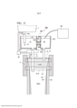
[0024] A Figura 1 é uma vista em corte transversal vertical que ilustra um aparelho de lingotamento contínuo para uma placa multicamada de acordo com uma primeira modalidade da presente invenção.[0024] Figure 1 is a vertical cross-sectional view illustrating a continuous casting apparatus for a multilayer slab in accordance with a first embodiment of the present invention.
[0025] A Figura 2 é uma vista em corte transversal em uma direção de A-A na Figura 1.[0025] Figure 2 is a cross-sectional view in an A-A direction in Figure 1.
[0026] A Figura 3 é uma vista esquemática em corte transversal para descrever um fluxo de aço fundido em um distribuidor e uma vista que ilustra um aparelho de lingotamento contínuo para uma placa multicamada da técnica relacionada.[0026] Figure 3 is a schematic cross-sectional view to depict a flow of molten steel in a distributor and a view illustrating a continuous casting apparatus for a multilayer plate of the related art.
[0027] A Figura 4 é uma vista esquemática em corte transversal para descrever o fluxo de aço fundido no distribuidor e uma vista que ilustra um aparelho de lingotamento contínuo para uma placa multicamada de acordo com a primeira modalidade da presente invenção.[0027] Figure 4 is a schematic cross-sectional view depicting the flow of molten steel in the distributor and a view illustrating a continuous casting apparatus for a multi-layer slab in accordance with the first embodiment of the present invention.
[0028] A Figura 5A é uma vista em corte transversal ampliada parcial do aparelho de lingotamento contínuo de uma placa multicamada de acordo com a primeira modalidade da presente invenção e uma vista que ilustra uma parte do distribuidor.[0028] Figure 5A is a partial enlarged cross-sectional view of the continuous casting apparatus of a multi-layer slab according to the first embodiment of the present invention and a view illustrating a part of the dispenser.
[0029] A Figura 5B é uma vista em corte transversal em uma direção de B-B na Figura 5A.[0029] Figure 5B is a cross-sectional view in a direction from B-B in Figure 5A.
[0030] A Figura 6 é uma vista em corte transversal na direção de BB na Figura 5A e uma vista que ilustra um primeiro exemplo de modificação do aparelho de fundição contínua.[0030] Figure 6 is a cross-sectional view in the direction of BB in Figure 5A and a view illustrating a first example of modification of the continuous casting apparatus.
[0031] A Figura 7 é uma vista em corte transversal na direção de B B na Figura 5A e uma vista que ilustra um segundo exemplo de modificação do aparelho de fundição contínua.[0031] Figure 7 is a cross-sectional view in the direction of B B in Figure 5A and a view illustrating a second example of modification of the continuous casting apparatus.
[0032] A Figura 8A é uma vista em corte transversal parcial ampliada que ilustra um terceiro exemplo de modificação do aparelho de fundição contínua.[0032] Figure 8A is an enlarged partial cross-sectional view illustrating a third example of modification of the continuous casting apparatus.
[0033] A Figura 8B é uma vista em corte transversal em uma direção de C-C na Figura 8A.[0033] Figure 8B is a cross-sectional view in a C-C direction in Figure 8A.
[0034] A Figura 9 é um diagrama padrão que ilustra a formação de um invólucro solidificado quando um cordão for dividido em dois segmentos por uma banda de campo magnético de corrente contínua e uma interface entre uma camada superficial e uma camada interna.[0034] Figure 9 is a standard diagram illustrating the formation of a solidified shell when a bead is divided into two segments by a band of direct current magnetic field and an interface between a surface layer and an inner layer.
[0035] A Figura 10 é um diagrama padrão para descrever um princípio de frenagem eletromagnética pelo campo magnético de corrente contínua, a Figura 10(a) é uma vista que ilustra um estado em que o campo magnético de corrente contínua é aplicado em um molde de fundição, e a Figura 10(b) é uma vista que ilustra um fluxo de uma corrente elétrica induzida gerada pelo campo magnético de corrente contínua.[0035] Figure 10 is a standard diagram to describe a principle of electromagnetic braking by the direct current magnetic field, Figure 10(a) is a view illustrating a state in which the direct current magnetic field is applied to a mold of casting, and Figure 10(b) is a view illustrating a flow of an induced electric current generated by the direct current magnetic field.
[0036] A Figura 11 é uma vista em corte transversal vertical que ilustra um aparelho de lingotamento contínuo para uma placa multicamada de acordo com uma segunda modalidade da presente invenção.[0036] Figure 11 is a vertical cross-sectional view illustrating a continuous casting apparatus for a multilayer slab in accordance with a second embodiment of the present invention.
[0037] A Figura 12A é uma vista esquemática em perspectiva que ilustra um estado em que duas bobinas solenoides são instaladas em uma periferia de um tubo de comunicação de um distribuidor no aparelho de fundição contínua.[0037] Figure 12A is a schematic perspective view illustrating a state in which two solenoid coils are installed on a periphery of a communication tube of a distributor in the continuous casting apparatus.
[0038] A Figura 12B é uma vista em corte transversal no caso de ser observada em um corte transversal perpendicular a uma linha de eixo geométrico central do tubo de comunicação no distribuidor e uma vista para descrever um princípio de frenagem eletromagnética pelas duas bobinas solenoides.[0038] Figure 12B is a cross-sectional view in the case of being observed in a cross-section perpendicular to a central geometric axis line of the communication tube in the distributor and a view to describe an electromagnetic braking principle by the two solenoid coils.
[0039] A Figura 13 é um diagrama padrão para descrever um princípio de frenagem eletromagnética pelo campo magnético de corrente contínua, a Figura 13(a) é uma vista que ilustra um estado em que um campo magnético de corrente contínua é aplicado ao aço fundido em um distribuidor constituído de um refratário, e a Figura 13(b) é uma vista que ilustra um fluxo de uma corrente elétrica induzida gerada pelo campo magnético de corrente contínua.[0039] Figure 13 is a standard diagram to describe a principle of electromagnetic braking by direct current magnetic field, Figure 13(a) is a view illustrating a state where a direct current magnetic field is applied to molten steel in a distributor consisting of a refractory, and Figure 13(b) is a view illustrating a flow of an induced electric current generated by the direct current magnetic field.
[0040] A Figura 14 é uma vista em corte transversal vertical que ilustra um aparelho de lingotamento contínuo para uma placa multicamada de acordo com uma terceira modalidade da presente invenção.[0040] Figure 14 is a vertical cross-sectional view illustrating a continuous casting apparatus for a multilayer slab in accordance with a third embodiment of the present invention.
[0041] A Figura 15A é um gráfico que ilustra uma relação entre uma razão de área de abertura e um grau de separação na camada superficial.[0041] Figure 15A is a graph illustrating a relationship between an opening area ratio and a degree of separation in the surface layer.
[0042] A Figura 15B é um gráfico que ilustra uma relação entre a razão de área de abertura e um grau de uniformidade de concentração.[0042] Figure 15B is a graph illustrating a relationship between the aperture area ratio and a degree of concentration uniformity.
[0043] A Figura 16A é um gráfico que ilustra uma relação entre um local de interface e o grau de separação na camada superficial.[0043] Figure 16A is a graph illustrating a relationship between an interface location and the degree of separation in the surface layer.
[0044] A Figura 16B é um gráfico que ilustra uma relação entre o local de interface e o grau de uniformidade de concentração.[0044] Figure 16B is a graph illustrating a relationship between the interface location and the degree of concentration uniformity.
[0045] A Figura 17 é um gráfico que ilustra uma distribuição de direção da largura de placa de uma espessura da camada superficial no caso em que um fluxo de redemoinho é alterado usando um dispositivo de agitação eletromagnética.[0045] Figure 17 is a graph illustrating a plate width direction distribution of a surface layer thickness in the case where a swirl flow is changed using an electromagnetic stirring device.
[0046] A Figura 18A é um gráfico que ilustra uma relação entre uma densidade de fluxo magnético que é aplicada no tubo de comunicação no distribuidor e o grau de separação na camada superficial.[0046] Figure 18A is a graph illustrating a relationship between a magnetic flux density that is applied to the communication tube in the distributor and the degree of separation in the surface layer.
[0047] A Figura 18B é um gráfico que ilustra uma relação entre a densidade de fluxo magnético que é aplicada no tubo de comunicação no distribuidor e o grau de uniformidade de concentração.[0047] Figure 18B is a graph illustrating a relationship between the magnetic flux density that is applied to the communication tube at the distributor and the degree of concentration uniformity.
[0048] A Figura 19A é um gráfico que ilustra uma relação entre uma razão de uma taxa de fluxo de aço fundido para uma área de um nível de superfície de aço fundido no distribuidor e o grau de separação e o grau de uniformidade de concentração no caso em que uma cabeça de aço fundido no distribuidor é constante.[0048] Figure 19A is a graph illustrating a relationship between a ratio of a flow rate of molten steel to an area of a surface level of molten steel in the distributor and the degree of separation and degree of concentration uniformity in the distributor. in which case a cast steel head in the distributor is constant.
[0049] A Figura 19B é um gráfico que ilustra uma relação entre uma razão de uma taxa de fluxo de aço fundido para uma área de um nível de superfície de aço fundido no distribuidor e o grau de separação e o grau de uniformidade de concentração no caso em que a cabeça de aço fundido no distribuidor muda à medida que o tempo passa.[0049] Figure 19B is a graph illustrating a relationship between a ratio of a flow rate of molten steel to an area of a surface level of molten steel in the distributor and the degree of separation and degree of concentration uniformity in the distributor. in which case the cast steel head on the distributor changes as time passes.
[0050] A Figura 20 é um gráfico que ilustra uma relação entre uma densidade de fluxo magnético que é aplicada à parte interna de um tubo de comunicação do distribuidor e o grau de separação na camada superficial e o grau de uniformidade de concentração no caso em que a cabeça de aço fundido no distribuidor muda à medida que o tempo passa.[0050] Figure 20 is a graph illustrating a relationship between a magnetic flux density that is applied to the inside of a distributor communication tube and the degree of separation in the surface layer and the degree of concentration uniformity in the case where that the cast steel head on the distributor changes as time passes.
[0051] Mais adiante neste documento, modalidades individuais da presente invenção serão descritas em detalhes com referência aos desenhos. Entretanto, no presente relatório descritivo e nos desenhos, aos elementos constituintes que têm substancialmente a mesma constituição funcional serão atribuídos o mesmo símbolo de referência e não serão descritos em duplicata.[0051] Later in this document, individual embodiments of the present invention will be described in detail with reference to the drawings. However, in the present specification and drawings, constituent elements that have substantially the same functional constitution will be assigned the same reference symbol and will not be described in duplicate.
[0052] A Figura 1 é uma vista em corte transversal vertical que ilustra um aparelho de lingotamento contínuo100 de uma placa multicamada de acordo com uma primeira modalidade da presente invenção (mais adiante neste documento, também simplesmente chamado de aparelho de lingotamento contínuo100). Além disso, a Figura 2 é uma vista em corte transversal em uma direção de A-A na Figura 1.[0052] Figure 1 is a vertical cross-sectional view illustrating a multi-layer plate
[0053] Conforme ilustrado na Figura 1 e na Figura 2, o aparelho de lingotamento contínuo100 inclui um molde de fundição 7 que tem um formato substancialmente retangular em uma vista plana que é constituído de um par de paredes de lado curto 7a e um par de paredes de lado longo (não ilustradas), um distribuidor 2 que fornece aço fundido à parte interna do molde de fundição 7, uma panela 1 que fornece aço fundido ao distribuidor 2, um dispositivo de adição 50 que adiciona um elemento predeterminado à parte interna do distribuidor 2 (mecanismo de adição), um dispositivo de controle 32, um dispositivo de agitação eletromagnética 9 disposto ao longo da direção de largura do molde de fundição 7, e um gerador de campo magnético de corrente contínua 8. Além disso, o aparelho de lingotamento contínuo100 é usado para fabricar placas multicamada que têm uma camada superficial e uma camada interna que tem composições multicamada diferentes.[0053] As illustrated in Figure 1 and Figure 2, the
[0054] A panela 1 tem um bocal longo 1a (bocal de fornecimento de aço fundido) fornecido sobre a superfície de fundo da mesma, retém aço fundido que é ajustado ao componente em uma etapa de refino secundária, e fornece o aço fundido ao distribuidor 2. Especificamente, o bocal longo 1a da panela 1 é inserido no distribuidor 2, e o aço fundido na panela 1 é fornecido ao distribuidor 2 através do bocal longo 1a. Entretanto, na Figura 1, um símbolo de referência 13 indica o fluxo do aço fundido ejetado da panela 1 até a parte interna do distribuidor 2.[0054]
[0055] O distribuidor 2 no aparelho de fundição continua 100 tem um formato substancialmente retangular em uma vista plana e tem uma porção de fundo 2a, um par de porções de parede de lado curto 2b e um par de porções de parede de lado longo 2c fornecidas na circunferência externa da porção de fundo 2a, e uma comporta em formato de placa 4 fornecida entre as superfícies internas do par de porções de parede de lado longo 2c. Além disso, no distribuidor 2, o aço fundido fornecido a partir da panela 1 é retido em um espaço formado pela porção de fundo 2a, o par de porções de parede de lado curto 2b, e o par de of porções de parede de lado longo 2c. Entretanto, o distribuidor 2 é constituído, por exemplo, de um refratário ou similares. Além disso, na porção de fundo 2a do distribuidor 2, um primeiro bocal de imersão 5 (primeiro bocal de imersão) e um segundo bocal de imersão 6 (segundo de imersão) que ejetam o aço fundido retido dentro do distribuidor 2 na parte interna do molde de fundição 7 são fornecidos.[0055] The
[0056] A comporta 4 no distribuidor 2 tem uma altura que é menor que aquela da porção de parede de lado curto 2b e a porção de parede de lado longo 2c e é fornecida na porção superior do par de porções de parede de lado longo 2c de modo que um vão seja formado entre a porção de fundo 2a e a comporta. Ou seja, o distribuidor 2 é dividido em duas seções pela comporta 4, e uma primeira câmara de retenção 11 (primeira porção de retenção) e uma segunda câmara de retenção 12 (segunda porção de retenção) são formadas. Além disso, uma porção de abertura 10 (trajetória de fluxo) que se comunica com a primeira câmara de retenção 11 e a segunda câmara de retenção 12 é formada entre ambas as câmaras de retenção.[0056] The
[0057] O primeiro bocal de imersão 5 é fornecido em uma porção que forma a primeira câmara de retenção 11 na porção de fundo 2a do distribuidor 2. Além disso, o primeiro bocal de imersão 5 ejeta aço fundido 21 na parte interna da primeira câmara de retenção 11 na parte interna do molde de fundição 7. Por outro lado, o segundo bocal de imersão 6 é fornecido em uma porção que forma a segunda câmara de retenção 12 na porção de fundo 2a do distribuidor 2. Além disso, o segundo bocal de imersão 6 ejeta aço fundido 22 na parte interna da segunda câmara de retenção 12 na parte interna do molde de fundição 7.[0057] The
[0058] O primeiro bocal de imersão 5 e o segundo bocal de imersão 6 têm comprimentos mutuamente diferentes e são inseridos na parte interna do molde de fundição 7. Especificamente, o primeiro bocal de imersão 5 é mais longo que o segundo bocal de imersão 6, e um furo de ejeção do primeiro bocal de imersão 5 está situado abaixo de um furo de ejeção do segundo bocal de imersão 6 na direção vertical.[0058] The
[0059] Além disso, o bocal longo 1a da panela 1 é inserido na parte interna da primeira câmara de retenção 11 do distribuidor 2. Além disso, no caso em que o distribuidor 2 é observado em uma vista plana conforme ilustrado na Figura 2, o bocal longo 1a da panela 1, o primeiro bocal de imersão 5 do distribuidor 2, e o segundo bocal de imersão 6 do distribuidor 2 são dispostos em série. Ou seja, o primeiro bocal de imersão 5 do distribuidor 2 está disposto em um local entre o bocal longo 1a da panela 1 e o segundo bocal de imersão 6 do distribuidor 2.[0059] Furthermore, the
[0060] O dispositivo de adição 50 injeta continuamente um fio ou similares no aço fundido 22 na parte interna da segunda câmara de retenção 12 do distribuidor 2. Portanto, o aço fundido 22 na parte interna da segunda câmara de retenção 12 do distribuidor 2 se torna o aço fundido 21 na primeira câmara de retenção 11 à qual um elemento predeterminado é adicionado e se torna o aço fundido que tem componentes diferentes do aço fundido 21 na parte interna da primeira câmara de retenção 11. Entretanto, o dispositivo de adição 50 é, por exemplo, um alimentador de fio ou similares.[0060] The
[0061] O elemento que é adicionado ao aço fundido não é particularmente limitado, e exemplos do mesmo incluem Ni, C, Si, Mn, P, S, B, Nb, Ti, Al, Cu, Mo e similares. Além disso, também é possível adicionar um elemento que está contido no aço como Ca, Mg ou REM que é um elemento de forte desoxidação e forte dessulfurização.[0061] The element that is added to molten steel is not particularly limited, and examples thereof include Ni, C, Si, Mn, P, S, B, Nb, Ti, Al, Cu, Mo and the like. In addition, it is also possible to add an element that is contained in steel such as Ca, Mg or REM which is an element of strong deoxidation and strong desulfurization.
[0062] O dispositivo de agitação eletromagnética 9 tem uma bobina eletromagnética e está disposto ao longo das superfícies externas de um par de paredes de lado longo do molde de fundição 7. Além disso, o dispositivo de agitação eletromagnética 9 tem uma função de agitar o aço fundido na porção superior na parte interna do molde de fundição 7. Além disso, o gerador de campo magnético de corrente contínua 8 está disposto abaixo do dispositivo de agitação eletromagnética 9, e o gerador de campo magnético de corrente contínua 8 aplica um campo magnético de corrente contínua na direção da espessura do molde de fundição 7.[0062] The
[0063] O dispositivo de controle 32 é conectado a um bocal deslizante 33b fornecido no primeiro bocal de imersão 5, um bocal deslizante 33c fornecido no segundo bocal de imersão 6, um bocal deslizante 33a fornecido no bocal longo 1a da panela 1, um medidor de nível superficial de aço fundido 31 e um dispositivo de pesagem 35 fornecido na panela 1. Um método de controle que usa esse dispositivo de controle 32 será descrito abaixo.[0063] The
[0064] A seguir, um método de fabricação de uma placa multicamada que usa o aparelho de lingotamento contínuo100 será descrito com o uso da Figura 1 e na Figura 9.[0064] Next, a method of manufacturing a multilayer board using the continuous casting apparatus100 will be described using Figure 1 and Figure 9.
[0065] Na fabricação de uma placa multicamada, o aço fundido é fornecido à parte interna do molde de fundição 7 a partir do primeiro bocal de imersão 5 e do segundo bocal de imersão 6 do distribuidor 2. Nesse momento, conforme descrito acima, o furo de ejeção do segundo bocal de imersão 6 está disposto acima do gerador de campo magnético de corrente contínua 8, e, por outro lado, o furo de ejeção do primeiro bocal de imersão 5 está disposto abaixo do gerador de campo magnético de corrente contínua 8. Portanto, o aço fundido 22 na parte interna da segunda câmara de retenção 12 do distribuidor 2 é ejetado de um local mais alto do que o aço fundido 21 na parte interna da primeira câmara de retenção 11 do distribuidor 2.[0065] In the manufacture of a multilayer plate, the cast steel is supplied to the inside of the casting
[0066] O molde de fundição 7 é resfriado com o uso de um dispositivo de resfriamento (não ilustrado) e, dessa forma, o aço fundido 22 fornecido à parte interna do molde de fundição 7 a partir do segundo bocal de imersão 6 é solidificado no molde de fundição 7, e um invólucro solidificado é formado. Além disso, o invólucro solidificado formado é puxado para baixo a uma velocidade de fundição predeterminada. O invólucro solidificado formado pela solidificação do aço fundido 22 se torna uma camada superficial 24 da placa multicamada que tem uma espessura D. Entretanto, o primeiro bocal de imersão 5 fornece o aço fundido 21 a partir de baixo do aço fundido 22 que é fornecido a partir do segundo bocal de imersão 6 e do gerador de campo magnético de corrente contínua 8 e, dessa forma, o aço fundido 21 é fornecido à parte interna de um espaço circundado pela camada superficial 24. Como resultado, o aço fundido 21 é fornecido para ser enterrado no espaço circundado pela camada superficial 24, e uma camada interna 25 da placa multicamada é fornecida. Portanto, uma placa multicamada que tem composições mutuamente diferentes na camada superficial e na camada interna pode ser fabricada.[0066] The casting
[0067] No método de fabricação descrito acima, a taxa de fluxo (a quantidade de aço fundido fornecido por unidade de tempo) do aço fundido 21 que é fornecido à parte interna do molde de fundição 7 a partir do primeiro bocal de imersão 5 e a taxa de fluxo do aço fundido 22 que é fornecido à parte interna do molde de fundição 7 do segundo bocal de imersão 6 são ajustadas de modo que um menisco 17 (superfície de aço fundido) na parte interna do molde de fundição 7 se torne constante. Especificamente, as taxas de fluxo dos aços fundidos 21 e 22 são respectivamente ajustadas de modo que a taxa de fluxo por unidade de tempo do aço fundido que é solidificado como a camada superficial 24 e consumido por ser puxado para baixo e a taxa de fluxo do aço fundido 22 que é fornecido à parte interna do molde de fundição 7 do segundo bocal de imersão 6 se tornam idênticas uma à outra e a taxa de fluxo por unidade de tempo do aço fundido que é solidificado como a camada interna 25 e consumido por ser puxado para baixo e a taxa de fluxo do aço fundido 21 que é fornecido à parte interna do molde de fundição 7 a partir do primeiro bocal de imersão 5 se tornem idênticas um à outra. Ou seja, o aço fundido 21 e o aço fundido 22 são fornecidos a partir do primeiro bocal de imersão 5 e do segundo bocal de imersão 6 respectivamente tanto quanto uma quantidade que é consumida como o invólucro solidificado. Portanto, no molde de fundição 7, uma interface 27 é formada entre o aço fundido 21 e o aço fundido 22, e um cordão é dividido em um reservatório de aço fundido de lado superior 15 e um reservatório de aço fundido de lado inferior 16.[0067] In the manufacturing method described above, the flow rate (the amount of molten steel supplied per unit of time) of the
[0068] Aqui, a razão entre a taxa de fluxo do aço fundido 21 e a taxa de fluxo do aço fundido 22 muda dependendo da espessura da camada superficial e da largura de fundição; no entanto, sob as condições de fundição de placas, a taxa de fluxo na camada interna (isto é, a taxa de fluxo do aço fundido 21) é quatro a dez vezes a taxa de fluxo na camada externa (ou seja, a taxa de fluxo do aço fundido 22), e a taxa de fluxo na camada interna se torna extremamente grande. Portanto, um fenômeno de fluxo de aço fundido é causado na parte interna do molde de fundição 7 devido ao fluxo do aço fundido que flui para fora do furo de ejeção do primeiro bocal de imersão 5 que fornece o aço fundido 21 ao reservatório de aço fundido de lado inferior 16. Especificamente, o fluxo de ejeção do aço fundido 21 colide com um invólucro solidificado 24 que forma a camada superficial e forma um fluxo reverso de lado inferior e um fluxo reverso de lado superior. Entre esses fluxos reversos, quando o fluxo reverso de lado superior for formado, o aço fundido 21 no reservatório de aço fundido de lado inferior 16 se move para o reservatório de aço fundido de lado superior 15 e, dessa forma, os aços fundidos no reservatório de aço fundido de lado inferior 16 e o reservatório de aço fundido de lado superior 15 são trocados entre si. Quando ocorre a troca descrita acima do aço fundido, o aço fundido 21 e o aço fundido 22 são misturados um ao outro e, dessa forma, as qualidades de uma placa multicamada se degradam.[0068] Here, the ratio between the flow rate of the
[0069] Para evitar a degradação de qualidade descrita acima, um campo magnético de corrente contínua que tem uma densidade de fluxo magnético uniforme é aplicado com o uso do gerador de campo magnético de corrente contínua 8 na direção da espessura do molde de fundição 7 para passar através da interface 27 ao longo do molde de fundição 7 na direção de largura (uma direção ortogonal à parede de lado curto 7a do molde de fundição 7), formando assim uma banda de campo magnético de corrente contínua 14. Aqui, a banda de campo magnético de corrente contínua 14 é formada na mesma faixa que a altura de núcleo do gerador de campo magnético de corrente contínua 8. Isso se deve ao fato de que, quando a banda de campo magnético de corrente contínua for formada na faixa descrita acima, um campo magnético de corrente contínua que tem uma densidade de fluxo magnético uniforme é aplicado.[0069] To avoid the quality degradation described above, a direct current magnetic field that has a uniform magnetic flux density is applied using the direct current
[0070] Um princípio de que a mistura do reservatório de aço fundido de lado superior 15 e do reservatório de aço fundido de lado inferior 16 pode ser evitada pela formação da banda de campo magnético de corrente contínua 14 usando o gerador de campo magnético de corrente contínua 8 será descrito.[0070] A principle that mixing of the upper side
[0071] A Figura 10 é um diagrama padrão para descrever um princípio de frenagem eletromagnética pelo campo magnético de corrente contínua, a Figura 10(a) é uma vista que ilustra um estado em que o campo magnético de corrente contínua é aplicado no molde de fundição, e a Figura 10(b) é uma vista que ilustra um fluxo de uma corrente elétrica induzida gerada pelo campo magnético de corrente contínua. Quando o aço fundido 41 atravessa um campo magnético de corrente contínua 40 gerado no molde de fundição como ilustrado na Figura 10(a), uma corrente elétrica induzida 42 flui de acordo com a regra da mão direita de Fleming. Nesse momento, o invólucro solidificado 23 está presente no molde de fundição 7 como ilustrado na Figura 10(b) e, dessa forma, um circuito elétrico da corrente elétrica induzida 42 é formado através do invólucro solidificado 23. Portanto, no aço fundido 41, devido à interação (regra da mão direita de Fleming) entre a corrente elétrica induzida 42 que flui em uma direção e o campo magnético de corrente contínua aplicado 40, uma força de frenagem 43 é exercida sobre o aço fundido em uma direção oposta ao fluxo do aço fundido 41. Portanto, devido à força de frenagem 43 que é exercida sobre o aço fundido 41, é possível suprimir o fluxo reverso de lado superior descrito acima e impedir a mistura entre o aço fundido 21 e o aço fundido 22 no molde de fundição.[0071] Figure 10 is a standard diagram to describe a principle of electromagnetic braking by the direct current magnetic field, Figure 10(a) is a view illustrating a state where the direct current magnetic field is applied to the mold of foundry, and Figure 10(b) is a view illustrating a flow of an induced electric current generated by the direct current magnetic field. When molten
[0072] No entanto, a densidade de fluxo magnético necessária para suprimir a mistura pode ser regulada usando o seguinte número de Stewart St que é expresso como a Expressão (1) abaixo e refere-se à razão entre a força de inércia e a força de frenagem.St=(aB2L)/(pVc) ••• Expressão (1)[0072] However, the magnetic flux density required to suppress mixing can be regulated using the following Stewart St number which is expressed as Expression (1) below and refers to the ratio of inertia force to force of braking.St=(aB2L)/(pVc) ••• Expression (1)
[0073] Aqui, quando St for 100 ou mais, é possível suprimir a mistura dos aços fundidos, e, quando calculado com uma condutividade elétrica de aço fundido (a) de 650.000 (S/m), uma densidade de aço fundido (p) de 7.200 (kg/m3), uma velocidade de fundição (Vc) de 0,0167 (m/s), um comprimento representativo (L) de (2WxT)/(W+T), uma largura de bloco fundido (W) de 0,8 (m), e uma espessura de bloco fundido (T) de 0,17 (m), uma densidade de fluxo magnético B para suprimir a mistura atinge aproximadamente 0,3 (T). Entretanto, o limite superior da densidade de fluxo magnético não é particularmente limitado, porém, é, de preferência grande; entretanto, em um caso em que o campo magnético de corrente contínua é formado sem o uso de um ímã supercondutor, o limite superior atinge aproximadamente 1,0 (T).[0073] Here, when St is 100 or more, it is possible to suppress mixing of the molten steels, and, when calculated with an electrical conductivity of molten steel (a) of 650,000 (S/m), a density of molten steel (p ) of 7,200 (kg/m3), a casting speed (Vc) of 0.0167 (m/s), a representative length (L) of (2WxT)/(W+T), a cast block width (W ) of 0.8 (m), and a molten block thickness (T) of 0.17 (m), a magnetic flux density B to suppress mixing reaches approximately 0.3 (T). However, the upper limit of the magnetic flux density is not particularly limited, but is preferably large; however, in a case where the direct current magnetic field is formed without the use of a superconducting magnet, the upper limit reaches approximately 1.0 (T).
[0074] Como descrito acima, quando as quantidades dos aços fundidos fornecidos à parte interna do molde de fundição 7 forem controladas e a frenagem eletromagnética for realizada com o uso do gerador de campo magnético de corrente contínua 8, é possível suprimir a mistura do aço fundido 21 e do aço fundido 22 na parte interna do molde de fundição 7.[0074] As described above, when the quantities of molten steels supplied to the inside of the casting
[0075] No entanto, para suprimir a degradação da qualidade de uma placa multicamada na fabricação da placa multicamada fornecendo o aço fundido 21 e o aço fundido 22 que têm composições diferentes à parte interna do molde de fundição 7 usando um distribuidor, é necessário suprimir a mistura do aço fundido 21 e do aço fundido 22 na parte interna do distribuidor 2.[0075] However, to suppress the quality degradation of a multilayer plate in the manufacture of the multilayer plate by supplying the
[0076] Em um distribuidor 80 da técnica relacionada (ou seja, um distribuidor não fornecido com a comporta 4) como ilustrado na Figura 3, o aço fundido derramado no distribuidor 80 através do bocal longo 1a a partir da panela 1 flui horizontalmente no distribuidor 80 e flui para fora e para baixo através de um bocal de imersão 81 fornecido na porção de fundo do distribuidor. Neste momento, em uma região 85 mais distante do bocal longo 1a da panela 1 do que do bocal de imersão 81, o fluxo do aço fundido não é gerado, e o aço fundido permanece estagnado.[0076] In a
[0077] Portanto, no aparelho de lingotamento contínuo100 de acordo com a primeira modalidade da presente invenção, os bocais de imersão são dispostos de modo que o primeiro bocal de imersão 5 do distribuidor 2 fique situado entre o bocal longo 1a da panela 1 e o segundo bocal de imersão 6 do distribuidor 2, como ilustrado na Figura 4. Além disso, no distribuidor 2, a comporta 4 é fornecida em um local entre o primeiro bocal de imersão 5 e o segundo bocal de imersão 6. Nesse caso, é possível fazer com que o aço fundido derramado a partir do bocal longo 1a da panela 1 flua em uma direção na parte interna do distribuidor 2 em direção ao primeiro bocal de imersão 5 e ao segundo bocal de imersão 6. Além disso, a comporta 4 permite a supressão do fluxo de aço fundido do segundo bocal de imersão 6 em direção ao primeiro bocal de imersão 5. Como resultado, é possível suprimir o movimento do aço fundido 22 na parte interna da segunda câmara de retenção 12 na parte interna da primeira câmara de retenção 11.[0077] Therefore, in the
[0078] Além disso, para impedir que o aço fundido 22 na segunda câmara de retenção 12 flua de volta para a primeira câmara de retenção 11, quando a área de um nível de superfície de aço fundido 18 na primeira câmara de retenção 11 for representada por ST1 (m2) (a área do aço fundido 21 na primeira câmara de retenção11 em um caso em que o distribuidor 2 é visto em uma vista plana), a área do nível de superfície de aço fundido 18 na segunda câmara de retenção 12 for representada por ST2 (m2) (a área do aço fundido 22 na segunda câmara de retenção 12 em um caso em que o distribuidor 2 é visto em uma vista plana), a quantidade de aço fundido fornecida à parte interna do molde de fundição 7 da primeira câmara de retenção 11 for representada por Q1 (kg/s), e a quantidade de aço fundido fornecida à parte interna do molde de fundição 7 da segunda câmara de retenção 12 for representada por Q2 (kg/s), as quantidades Q1 e Q2 de aço fundido fornecido são controladas para satisfazer Expressão (2) abaixo. (QI/STI)<(Q2/ST2) ••• Expressão (2).[0078] Further, to prevent
[0079] Em um caso em que as quantidades Q1 e Q2 de aço fundido fornecido satisfazem a Expressão (2), o nível de superfície de aço fundido 18 na parte interna da segunda câmara de retenção 12 descende mais rápido do que o nível de superfície de aço fundido 18 na parte interna da primeira câmara de retenção 11 e, dessa forma, o aço fundido é fornecido a partir da primeira câmara de retenção 11 até a segunda câmara de retenção 12 para remover a diferença principal. Portanto, é possível suprimir adicionalmente o movimento do aço fundido 22 na segunda câmara de retenção 12 até a primeira câmara de retenção 11.[0079] In a case where the quantities Q1 and Q2 of molten steel supplied satisfy Expression (2), the surface level of
[0080] Além disso, no aparelho de lingotamento contínuo 100, o dispositivo de adição 50 injeta um fio ou similares na segunda câmara de retenção 12 do distribuidor 2 como descrito acima, adicionando assim um elemento predeterminado ou liga ao aço fundido 22 na parte interna da segunda câmara de retenção 12 (referir-se à Figura 1). Portanto, é possível fabricar o aço fundido 22 que tem uma composição diferente do aço fundido 21 na primeira câmara de retenção 11 na segunda câmara de retenção 12. Entretanto, a quantidade do fio ou similares que é injetada na segunda câmara de retenção 12 pode ser adequadamente ajustada dependendo da quantidade do aço fundido que é fornecido à parte interna da segunda câmara de retenção 12 a partir da primeira câmara de retenção 11.[0080] Furthermore, in the
[0081] Portanto, no distribuidor 2, é possível suprimir o fluxo do aço fundido a partir do segundo bocal de imersão 6 em direção ao primeiro bocal de imersão 5 e, dessa forma, o movimento do aço fundido 21 até a primeira câmara de retenção 11 pode ser suprimido. Ou seja, a mistura entre o aço fundido 21 e o aço fundido 22 é suprimida e, é possível reter de maneira estável o aço fundido 21 e o aço fundido 22 na parte interna de um distribuidor.[0081] Therefore, in the
[0082] Entretanto, para a segunda câmara de retenção 12, o elemento predeterminado ou liga é adicionado com o uso do fio ou similares, e assim é preferível conferir uma força de agitação, por exemplo, a partir da porção de fundo 2a do distribuidor 2 por borbulhamento de Ar ou similares e tornar a concentração de aço fundido 22 na parte interna da segunda câmara de retenção 12, uniforme.[0082] However, for the
[0083] Aqui, conforme ilustrado na Figura 5A e na Figura 5B, a porção de abertura 10 do distribuidor 2 permite a comunicação do aço fundido 21 na primeira câmara de retenção 11 e do aço fundido 22 na segunda câmara de retenção 12 através da porção de abertura 10. Entretanto, na Figura 5B (uma vista em corte transversal em uma direção de B-B na Figura 5A), um símbolo de referência 26 (porção pontilhada) representa uma porção da comporta 4 que é imersa no aço fundido, e um símbolo de referência 18 representa o menisco (superfície de aço fundido) do aço fundido na parte interna do distribuidor 2. Ou seja, o símbolo de referência 26 representa uma porção da comporta 4 em que o aço fundido 21 e o aço fundido 22 se sobrepõem no caso de serem observados em uma direção perpendicular à superfície da comporta 4.[0083] Here, as illustrated in Figure 5A and Figure 5B, the opening
[0084] Além disso, a razão de área de abertura da comporta 4 é, de preferência, 10% ou mais e 70% ou menos. Entretanto, a "razão de área de abertura" da comporta 4 se refere a um valor (%) obtido dividindo-se a área da porção de abertura 10 (a área de uma região circundada por uma superfície de fundo 4a da comporta 4, as superfícies internas do par de porções de parede de lado longo 2c, e uma superfície interna da porção de fundo 2a) pela área do aço fundido 21 na parte interna da primeira câmara de retenção 11 do distribuidor 2 (ou seja, a área de uma região circundada pelo nível de superfície de aço fundido 18, as superfícies internas do par de porções de parede de lado longo 2c, e a superfície interna da porção de fundo 2a) no caso de serem observadas em uma direção perpendicular à superfície da comporta 4 (no caso de serem observadas em uma direção em que a porção de abertura 10 se comunica com a primeira câmara de retenção 11 e a segunda câmara de retenção 12). Em outras palavras, a "razão de área de abertura" da comporta 4 refere-se à proporção (%) da área de corte transversal da porção de abertura 10 na área de corte transversal do aço fundido 21 na parte interna da primeira câmara de retenção 11 no caso de ser observada em um corte transversal perpendicular à direção de comunicação da porção de abertura 10 (uma direção perpendicular à superfície da comporta 4).[0084] Furthermore, the opening area ratio of the
[0085] Quando a razão de área de abertura da comporta 4 for ajustada para 70% ou menos, é possível suprimir ainda mais a mistura dos aços fundidos na primeira câmara de retenção 11 e na segunda câmara de retenção 12. Portanto, a razão de área de abertura da comporta 4 é, de preferência, 70% ou menos. Por outro lado, em um caso em que a razão de área de abertura da comporta 4 é menor que 10%, a perda de pressão se torna grande quando o aço fundido fluir a partir da primeira câmara de retenção 11 para a segunda câmara de retenção 12, e há uma preocupação de que uma irregularidade de componentes possa ser causada. Portanto, a razão de área de abertura da comporta 4 é, de preferência, 10% ou mais.[0085] When the opening area ratio of
[0086] Além disso, com referência ao formato da comporta 4, um furo atravessante redondo é fornecido na comporta 4 conforme ilustrado na Figura 6, esse furo atravessante pode ser usado como a porção de abertura 10. Além disso, um entalhe é fornecido na comporta 4 como ilustrado na Figura 7, e esse entalhe pode ser usado como a porção de abertura 10. Além disso, outra comporta 4’ pode ser fornecida imediatamente abaixo da comporta 4 com um vão predeterminado entre as mesmas conforme ilustrado na Figura 8A e na Figura 8B. Nesse caso, um vão entre a comporta 4 e a comporta 4’ se torna a porção de abertura 10.[0086] Also, with reference to the shape of the
[0087] Conforme descrito anteriormente, na fabricação de uma placa multicamada, o cordão é dividido em dois segmentos pela banda de campo magnético de corrente contínua 14 formada no molde de fundição 7, e os aços fundidos são respectivamente fornecidos a partir da primeira câmara de retenção 11 e da segunda câmara de retenção 12 do distribuidor 2 tanto quanto as quantidades Q1 e Q2 de aços fundidos que são consumidos por solidificação nas respectivas regiões (com referência à Figura 1 e na Figura 9). Quando a quantidade de aço fundido que é consumida por solidificação no molde de fundição 7 for representada por Q (kg/s), a velocidade de fundição é representada por Vc (kg/s), a área da porção de camada interna da placa é representada por S1 (m2), a área da camada superficial da placa é representada por S2 (m2), a densidade do aço fundido 21 é representada por pi (kg/m3), e a densidade do aço fundido 22 é representada por p 2 (kg/m3), as quantidades descritas anteriormente Q, Q1 e Q2 de aço fundido são representadas pelas Expressões (3) a (5). Q= Q1+Q2 Expressão (3) Q1=p1S1Vc Expressão (4) Q2=p2S2Vc Expressão (5)[0087] As previously described, in the manufacture of a multilayer plate, the bead is divided into two segments by the direct current
[0088] Além disso, em um método de lingotamento contínuo para uma placa multicamada de acordo com a presente invenção, as quantidades Q, Q1 e Q2 de aço fundido são controladas de modo que a interface 27 entre o aço fundido 21 e o aço fundido 22 no molde de fundição 7 fique situada na banda de campo magnético de corrente contínua 14. Descreve-se um método de controle específico usando a Figura 1.[0088] Furthermore, in a continuous casting method for a multilayer slab in accordance with the present invention, the quantities Q, Q1 and Q2 of molten steel are controlled so that the
[0089] Primeiramente, a razão de área de abertura do bocal deslizante 33a proporcionado no bocal longo 1a da panela 1 é controlada de modo que a quantidade Q de aço fundido que é fornecida para dentro do distribuidor 2 a partir da panela 1 se torne constante. Nesse momento, é possível medir o peso da panela 1 usando o dispositivo de ponderação 35a e computar a quantidade Q de aço fundido com base na quantidade do peso alterado por unidade de tempo. Entretanto, a quantidade Q de aço fundido pode ser computada dispondo-se o dispositivo de ponderação 35a imediatamente abaixo do distribuidor 2 e medindo-se a quantidade do peso do distribuidor 2 alterado.[0089] First, the opening area ratio of the sliding
[0090] Quando a quantidade Q de aço fundido for ajustada como sendo constante, a cabeça de aço fundido (o nível de superfície de aço fundido 18 do aço fundido na parte interna do distribuidor 2) dentro do distribuidor 2 é retida em um local de altura constante. Nesse estado, a taxa de fluxo Q1 do aço fundido 21 que é consumido na porção inferior do cordão (o reservatório de aço fundido de lado inferior 16) é controlada para que seja constante. De modo específico, a cabeça de aço fundido na parte interna do distribuidor 2 é retida em um local de altura constante, e a razão de área de abertura do bocal deslizante 33b é retida em um nível constante usando uma tabela pré-especificada da razão de área de abertura do bocal deslizante 33b e a taxa de fluxo, controlando, assim, a quantidade Q1 de aço fundido a ser constante. No entanto, o controle da quantidade Q1 de aço fundido por si só como sendo constante não é suficiente para a quantidade Q de aço fundido que é fornecida para dentro do molde de fundição 7, e, logo, a quantidade Q2 de aço fundido do aço fundido ajustado por componente 22 é controlada controlando-se a razão de área de abertura do bocal deslizante 33c de modo que o nível de superfície de aço fundido (o local do menisco 17 do aço fundido na parte interna do molde de fundição 7) dentro do molde de fundição 7 se torne constante. Como resultado, a quantidade Q de aço fundido e as quantidades Q1 e Q2 de aços fundidos que são consumidas nas porções superiores e inferiores do cordão podem ser controladas, e é possível manter estavelmente a interface 27 entre o aço fundido 21 e o aço fundido 22 ilustrados na Figura 1. Ou seja, é possível controlar o local da interface 27 que é especificada pelo equilíbrio entre a quantidade Q1 de aço fundido e a quantidade Q2 de aço fundido como estando em uma faixa da banda de campo magnético de corrente contínua 14.[0090] When the quantity Q of molten steel is set constant, the molten steel head (the molten
[0091] Entretanto, no controle descrito anteriormente, pode-se considerar um problema da relação entre a razão de área de abertura do bocal deslizante 33b e a taxa de fluxo não sendo sempre constante do controle. Portanto, é necessário compreender a relação entre a razão de área de abertura do bocal deslizante 33b e a característica de taxa de fluxo usando o tempo de início de fundição e corrigir a característica. No tempo de início de fundição, os componentes do aço fundido 22 na parte interna da segunda câmara de retenção 12 não são ajustados, e, logo, somente o aço fundido 21 ejetado a partir do primeiro bocal de imersão 5 é fundido. Nesse momento, a cabeça de aço fundido na parte interna do distribuidor 2 é ajustada como sendo constante, o nível de superfície de aço fundido na parte interna do molde de fundição 7 é controlado como sendo constante, e a relação entre a razão de área de abertura do bocal deslizante 33b e a taxa de fluxo é ajustada, desse modo, torna-se possível ajustar a taxa de fluxo.[0091] However, in the control described above, it can be considered a problem of the relationship between the ratio of the opening area of the sliding
[0092] Até o momento, descreveu-se um caso no qual o aço fundido é continuamente fornecido ao distribuidor 2 a partir da panela 1; no entanto, o aço fundido não é fornecido a partir da panela até o distribuidor, por exemplo, no momento de trocar panelas ou na fase final de fundição, e, logo, não é possível controlar a cabeça de aço fundido na parte interna do distribuidor 2 como sendo constante (a cabeça de aço fundido na parte interna do distribuidor 2 desce à medida que o aço fundido é fornecido para dentro do molde de fundição 7 a partir do distribuidor 2). No entanto, mesmo sob condições onde a cabeça de aço fundido na parte interna do distribuidor 2 se altera, é possível lidar com o caso descrito anteriormente obtendo-se previamente a relação entre a razão de área de abertura do bocal deslizante e da taxa de fluxo. Ou seja, a taxa de fluxo de aço fundido fornecida ao molde de fundição é regulada com base no tamanho da placa e na velocidade de fundição, e, logo, mesmo quando a cabeça na parte interna do distribuidor 2 for alterada, é necessário controlar a taxa de fluxo do aço fundido 21 para que seja mantida constante e, adicionalmente, controlar a taxa de fluxo do aço fundido 22 de modo que o nível de superfície de aço fundido na parte interna do molde de fundição 7 se torne constante.[0092] So far, a case has been described in which molten steel is continuously supplied to
[0093] Mesmo sob condições onde a cabeça de aço fundido na parte interna do distribuidor 2 não é mantida constante conforme descrito anteriormente (por exemplo, condições onde o suprimento do aço fundido a partir da panela termina), quando a área do nível de superfície de aço fundido 18 na primeira câmara de retenção 11 for representada por ST1 (m2), a área do nível de superfície de aço fundido 18 na segunda câmara de retenção 12 é representada por ST2 (m2), a quantidade de aço fundido fornecida para dentro do molde de fundição 7 a partir da primeira câmara de retenção 11 é representada por Q1 (kg/s), e a quantidade de aço fundido fornecida para dentro do molde de fundição 7 a partir da segunda câmara de retenção 12 é representada por Q2 (kg/s) conforme descrito anteriormente, a área ST1 do nível de superfície de aço fundido 18 na primeira câmara de retenção 11 e a área ST2 do nível de superfície de aço fundido 18 na segunda câmara de retenção 12 são ajustadas dependendo das quantidades Q1 e Q2 de aço fundido fornecidas a fim de satisfazer a Expressão (2).[0093] Even under conditions where the molten steel head on the inside of
[0094] Em um caso onde as quantidades Q1 e Q2 de aço fundido fornecidas satisfazem a Expressão (2), o nível de superfície de aço fundido 18 na parte interna da segunda câmara de retenção 12 desce mais rápido que o nível de superfície de aço fundido 18 na parte interna da primeira câmara de retenção 11, e, logo, o aço fundido é fornecido a partir da primeira câmara de retenção 11 à segunda câmara de retenção 12 a fim de remover a diferença de cabeça. Portanto, é possível suprimir o aço fundido 22 na segunda câmara de retenção 12 movendo-se à primeira câmara de retenção 11, e, consequentemente, mesmo em um estado onde o aço fundido não é fornecido a partir da panela, é possível suprimir a mistura do aço fundido 21 na parte interna da primeira câmara de retenção 11 e do aço fundido 22 na parte interna da segunda câmara de retenção 12.[0094] In a case where the quantities Q1 and Q2 of molten steel supplied satisfy Expression (2), the surface level of
[0095] Entretanto, o cordão é dividido em porções superiores e inferiores usando o campo magnético de corrente contínua conforme descrito anteriormente, mas a quantidade de aço fundido que é fornecida ao reservatório de porção superior acima da banda de campo magnético de corrente contínua se torna menor que a quantidade de aço fundido que é fornecida ao reservatório de porção inferior. Portanto, como um meio para tornar a solidificação do aço fundido uniforme na parte interna do molde de fundição 7, é preferível dispor o dispositivo de agitação eletromagnética 9, próximo à superfície de aço fundido na parte interna do molde de fundição 7. Nesse caso, é possível conferir um fluxo de redemoinho na parte interna de um corte transversal horizontal e tornar o fluxo de aço fundido e a solidificação uniformes na direção circunferencial.[0095] However, the bead is divided into upper and lower portions using the dc magnetic field as described above, but the amount of molten steel that is supplied to the upper portion reservoir above the dc magnetic field band becomes less than the amount of molten steel that is supplied to the lower portion sump. Therefore, as a means to make the solidification of the molten steel uniform inside the casting
[0096] Conforme descrito anteriormente, de acordo com o aparelho de lingotamento contínuo100 de acordo com a presente modalidade, os bocais de imersão são dispostos em uma ordem do bocal longo 1a da panela 1, o primeiro bocal de imersão 5 do distribuidor 2, e o segundo bocal de imersão 6 do distribuidor 2 (ou seja, o bocal longo 1a da panela 1 não é disposto entre o primeiro bocal de imersão 5 e o segundo bocal de imersão 6), e, logo, é possível gerar um fluxo de aço fundido em uma direção a partir do bocal longo 1a da panela 1 em direção ao primeiro bocal de imersão 5 e ao segundo bocal de imersão 6 do distribuidor 2 na parte interna do distribuidor 2. Além disso, o distribuidor 2 é particionado na primeira câmara de retenção 11 e na segunda câmara de retenção 12 proporcionando-se a comporta 4, e, logo, é possível evitar que o aço fundido na parte interna da segunda câmara de retenção 12 se mova para dentro da primeira câmara de retenção 11. Adicionalmente, o elemento predeterminado é adicionado ao aço fundido na parte interna da segunda câmara de retenção 12, e, logo, é possível fabricar aço fundido tendo uma composição diferente do aço fundido na parte interna da primeira câmara de retenção 11 na segunda câmara de retenção 12. Portanto, é possível reter aços fundidos tendo diferentes composições em um distribuidor enquanto suprime a mistura das mesmas. Como resultado, é possível suprimir a degradação de qualidade durante a fabricação de uma placa multicamada usando uma panela e um distribuidor.[0096] As previously described, according to the
[0097] A seguir, descreve-se um aparelho de lingotamento contínuo 200 de acordo com uma segunda modalidade da presente invenção.[0097] The following describes a
[0098] A Figura 11 é uma vista em corte transversal vertical que ilustra o aparelho de lingotamento contínuo 200 de acordo com a presente modalidade. Na primeira modalidade descrita anteriormente, descreveu-se um caso onde o distribuidor 2 é particionado na primeira câmara de retenção 11 e na segunda câmara de retenção 12 pela comporta 4. Em contrapartida, em um distribuidor 202 do aparelho de lingotamento contínuo 200 de acordo com a presente modalidade, conforme ilustrado na Figura 11, uma primeira câmara de retenção 211 e uma segunda câmara de retenção 212 são comunicadas entre si através de um tubo de comunicação 210, e um gerador de campo magnético de corrente contínua 240 é disposto na periferia do tubo de comunicação 210.[0098] Figure 11 is a vertical cross-sectional view illustrating the
[0099] O gerador de campo magnético de corrente contínua 240 tem um par de bobinas solenoides 241 e 242 conforme ilustrado na Figura 11 e na Figura 12A. Além disso, essas bobinas solenoides 241 e 242 ficam uma voltada para outra e são dispostas fora do tubo de comunicação 210 a fim de circundar o tubo de comunicação 210.[0099] The DC
[00100] No distribuidor 202 do aparelho de lingotamento contínuo 200, a primeira câmara de retenção 211 e a segunda câmara de retenção 212 comunicam-se entre si através do tubo de comunicação 210 conforme descrito anteriormente, e, logo, similar ao caso da primeira modalidade, é possível suprimir a mistura do aço fundido 21 na parte interna da primeira câmara de retenção 211 e do aço fundido 22 na parte interna da segunda câmara de retenção 212. Entretanto, similar ao caso da primeira modalidade, a razão de área de abertura do tubo de comunicação 210 é, de preferência, 10% ou maior e 70% ou menor.[00100] In the
[00101] Além disso, no aparelho de lingotamento contínuo 200, as bobinas solenoides 241 e 242 que geram campos magnéticos na parte interna do tubo de comunicação 210 são dispostas na periferia do tubo de comunicação 210 conforme descrito anteriormente. Nesse momento, nas bobinas solenoides 241 e 242, conforme ilustrado na Figura 12A, a direção de aplicação de uma corrente elétrica ou a direção do bobinamento é ajustada de modo que os campos magnéticos que são gerados pelas respectivas bobinas solenoides fiquem uns voltados para os outros. Quando campos magnéticos tendo orientações mutuamente opostas forem formados conforme descrito anteriormente, linhas de campo magnético radiais externas (ou internas) 245 são formadas entre as bobinas solenoides 241 e 242 conforme ilustrado na Figura 12A e na Figura 12B. Quando o aço fundido atravessar as linhas de campo magnético descritas anteriormente 245, no caso de ser observado em um corte transversal perpendicular à linha de eixo geométrico central do tubo de comunicação 210, forma-se um circuito elétrico ao longo da direção circunferencial. Além disso, a formação desse circuito elétrico induz uma corrente elétrica induzida 246 a fluir ao longo da direção circunferencial no aço fundido na parte interna do tubo de comunicação 210. Como resultado, é possível quebrar confiavelmente o aço fundido que flui na parte interna do tubo de comunicação de refratário 210 e, ainda, suprimir a mistura do aço fundido 21 na parte interna da primeira câmara de retenção 211 e do aço fundido 22 na parte interna da segunda câmara de retenção 212. Entretanto, na Figura 12B, uma referência numérica 250 indica a direção de aço fundido que flui na parte interna do tubo de comunicação 210.[00101] Furthermore, in the
[00102] No presente documento, descreve-se a razão para dispor as duas bobinas solenoides 241 e 242 no tubo de comunicação 210. A Figura 13 é uma vista correspondente à Figura 10 e um diagrama de padrão que descreve um estado onde um campo magnético de corrente contínua é aplicado ao aço fundido 41 circundado pelo refratário 44. Conforme descrito anteriormente, na Figura 10, o aço fundido 41 é circundado pelo invólucro solidificado 23, e, logo, quando um campo magnético de corrente contínua for aplicado, é possível formar um circuito elétrico de uma corrente elétrica induzida através do invólucro solidificado 23 e formar a corrente elétrica induzida 42 que flui em uma direção no aço fundido 41. Por outro lado, em um caso onde o aço fundido 41 é circundado pelo refratário 44 conforme ilustrado na Figura 13, nenhuma corrente elétrica flui no refratário 44, e, logo, é necessário formar um circuito elétrico no aço fundido 41. Nesse caso, no aço fundido 41, próximo à superfície interna do refratário 44, uma corrente elétrica tendo uma orientação oposta a uma corrente elétrica que flui na porção central do aço fundido 41, ou seja, uma força que acelera o fluxo atua, e, consequentemente, uma força de frenagem não atua. Portanto, somente quando uma bobina solenoide for disposta no tubo de comunicação de refratário 210, não é possível induzir uma força de frenagem a agir sobre o aço fundido na parte interna do tubo de comunicação 210. Portanto, no aparelho de lingotamento contínuo 200, as duas bobinas solenoides 241 e 242 são dispostas.[00102] In the present document, the reason for arranging the two
[00103] Entretanto, um método para fabricar uma placa multicamada usando o aparelho de lingotamento contínuo 200 é igual ao caso na primeira modalidade e, logo, não será descrito.[00103] However, a method for fabricating a multilayer slab using the
[00104] A seguir, descreve-se um aparelho de lingotamento contínuo300 de acordo com uma terceira modalidade da presente invenção.[00104] The following describes a
[00105] A Figura 14 é uma vista em corte transversal vertical que ilustra o aparelho de lingotamento contínuo 300 de acordo com a presente modalidade. Na primeira modalidade, descreveu-se um caso onde o primeiro bocal de imersão 5 é proporcionado na primeira câmara de retenção 11 do distribuidor 2 e o segundo bocal de imersão 6 é proporcionado na segunda câmara de retenção 12 do distribuidor 2. Em contrapartida, o aparelho de lingotamento contínuo 300 de acordo com a presente modalidade é diferente do aparelho de lingotamento contínuo 100 de acordo com a primeira modalidade pelo fato de que o segundo bocal de imersão 6 é proporcionado na primeira câmara de retenção 11 do distribuidor 2 e o primeiro bocal de imersão 5 é proporcionado na segunda câmara de retenção 12 do distribuidor 2 conforme ilustrado na Figura 14.[00105] Figure 14 is a vertical cross-sectional view illustrating the
[00106] Ou seja, no aparelho de lingotamento contínuo 300 de acordo com a presente modalidade, o aço fundido 21 na parte interna da primeira câmara de retenção 11 é ejetado para dentro do molde de fundição 7 através do segundo bocal de imersão 6 da primeira câmara de retenção 11 do distribuidor 2, e o aço fundido 22 na parte interna da segunda câmara de retenção 12 é ejetado para dentro do molde de fundição 7 através do primeiro bocal de imersão 5 da segunda câmara de retenção 12 do distribuidor 2. Como resultado, em um caso onde uma placa multicamada é fabricada usando o aparelho de lingotamento contínuo 300 de acordo com a presente modalidade, a área da camada superficial da placa é formada usando o aço fundido 21 na parte interna da primeira câmara de retenção 11, e a porção de camada interna da placa é formada usando o aço fundido 22 na parte interna da segunda câmara de retenção 12. Entretanto, um método para fabricar uma placa multicamada usando o aparelho de lingotamento contínuo 300 é igual ao caso da primeira modalidade e, logo, não será descrito.[00106] That is, in the
[00107] A seguir, descrevem-se exemplos realizados para confirmar os efeitos de ação da presente invenção.[00107] Next, examples performed to confirm the effects of action of the present invention are described.
[00108] Uma placa multicamada tendo uma largura de 800 (mm) e uma espessura de 170 (mm) foi fabricada usando o aparelho de lingotamento contínuo 100 de acordo com a primeira modalidade. Nesse momento, o dispositivo de agitação eletromagnética 9 foi disposto de modo que o centro de núcleo do dispositivo de agitação eletromagnética 9 ficasse localizado 75 (mm) abaixo do nível de superfície de aço fundido (o local do menisco 17) na parte interna do molde de fundição 7, e um fluxo de redemoinho tendo uma velocidade máxima de 0,6 (m/s) foi conferido em um corte transversal horizontal próximo à superfície de aço fundido (o menisco 17) na parte interna do molde de fundição 7. Adicionalmente, o gerador de campo magnético de corrente contínua 8 foi disposto de modo que o centro de núcleo do gerador de campo magnético de corrente contínua 8 fosse localizado 400 (mm) abaixo do nível de superfície de aço fundido. Entretanto, a espessura de núcleo do gerador de campo magnético de corrente contínua 8, era de 200 (mm), e um máximo de 0,5 (T) de um campo magnético de corrente contínua tendo uma densidade de fluxo magnético quase uniforme foi aplicado em uma faixa de 300 a 500 (mm) a partir do nível de superfície de aço fundido.[00108] A multilayer slab having a width of 800 (mm) and a thickness of 170 (mm) was fabricated using the
[00109] A especificação do distribuidor 2 foi ajustada conforme descrito abaixo. A capacidade do distribuidor 2, era de 20 (t) e o intervalo entre o primeiro bocal de imersão 5 e o segundo bocal de imersão 6 do distribuidor 2 foi ajustada para 400 (mm). A comporta 4 foi instalada no local intermediário entre os bocais, e a profundidade da comporta 4 foi alterada dependendo das condições. Adicionalmente, a área ST1 do nível de superfície de aço fundido na primeira câmara de retenção 11 e a área ST2 do nível de superfície de aço fundido na segunda câmara de retenção 12 foram ajustadas dependendo das quantidades Q1 e Q2 de aço fundido fornecidas a fim de satisfazer a Expressão (2).[00109]
[00110] Os locais dos orifícios de ejeção do primeiro bocal de imersão 5 e do segundo bocal de imersão 6 na direção de largura do molde de fundição 7 foram ajustados para 1/4 locais de largura respectivamente com o centro de largura interposto entre os mesmos. Além disso, os locais dos orifícios de ejeção do primeiro bocal de imersão 5 e do segundo bocal de imersão 6 na direção de profundidade do molde de fundição 7 foram ajustados para que ficassem abaixo e acima da banda de campo magnético de corrente contínua 14 que foi formada usando o gerador de campo magnético de corrente contínua 8 respectivamente. De modo específico, o local de altura do orifício de ejeção do segundo bocal de imersão 6 que forneceu o aço fundido 22 que serviu para formar uma camada superficial foi ajustado para 150 (mm) a partir do nível de superfície de aço fundido, e o local de altura do orifício de ejeção do primeiro bocal de imersão 5 que forneceu o aço fundido 21 que serviu para formar uma camada interna foi ajustado para 550 (mm) a partir do nível de superfície de aço fundido.[00110] The locations of the ejection holes of the
[00111] O coeficiente de solidificação K (mm/min0,5) na parte interna do molde de fundição 7, era de aproximadamente 25 e a velocidade de fundição Vc (m/min) foi ajustada para 1. A espessura da camada superficial D (mm) (com referência à Figura 9) da placa no local do centro de núcleo do gerador de campo magnético de corrente contínua 8 foi computada a partir do coeficiente de solidificação K, a velocidade de fundição Vc, e a altura H (=400 (mm): com referência à Figura 9) a partir do nível de superfície de aço fundido até o centro de núcleo do gerador de campo magnético de corrente contínua 8 usando a Expressão (6) abaixo e constatou-se ser aproximadamente 16 (mm). As taxas de fluxo do aço fundido 21 e do aço fundido 22 foram reguladas a partir da espessura da camada superficial D.D=K^(H/Vc) ... Expressão (6)[00111] The solidification coefficient K (mm/min0.5) inside the casting
[00112] Independentemente do controle das taxas de fluxo do aço fundido 21 e do aço fundido 22, no momento de iniciar a fundição, somente o aço fundido 21 foi usado na fundição, e a razão de área de abertura do bocal deslizante para fornecer uma taxa de fluxo de aço fundido necessária foi confirmada. Após isso, a quantidade de despejamento a partir da panela 1 foi controlada para que fosse constante de modo que a cabeça de aço fundido na parte interna do distribuidor 2 se tornasse constante, e, então, a razão de área de abertura do bocal deslizante foi controlada para que fosse constante. Adicionalmente, para o aço fundido 22, a quantidade de despejamento foi controlada de modo que o nível de superfície de aço fundido se tornasse constante.[00112] Regardless of the flow rate control of
[00113] Assim como o aço fundido que foi fornecido a partir da panela 1 ao distribuidor 2, utilizou-se aço acalmado ao Al com baixo teor de carbono. Ou seja, o aço fundido 21 era aço acalmado ao Al com baixo teor de carbono. Entretanto, à segunda câmara de retenção 12 do distribuidor 2, um fio de ferro (contendo grãos de Ni na parte interna: (420 g/m)) rebitado com uma placa de aço macio com 0,3 mm de espessura foi adicionado usando um alimentador de fio em uma velocidade de adição de 3 (m/min). Ou seja, o aço fundido 22 era o aço fundido 21 ao qual o fio de ferro descrito anteriormente foi adicionado. Entretanto, a adição descrita anteriormente do fio de ferro (a adição do fio de ferro descrito anteriormente em uma velocidade de adição de 3 (m/min)) corresponde à adição de 0,5% de Ni ao aço fundido 21.[00113] As well as the cast steel that was supplied from
[00114] Com o intuito de inspecionar a distribuição de concentração de Ni na placa multicamada, independentemente da distribuição de concentração na camada superficial, espécimes de análise foram amostrados em locais centrais de ambos os lados curtos (dois locais), locais com 1/4 da largura (quatro locais), e locais com 1/2 da largura (dois locais) em um local 8 mm afastado da superfície (o centro da espessura de camada superficial), e as concentrações foram inspecionadas. Além disso, independentemente da distribuição de concentração na camada interna, espécimes de análise foram amostrados em locais centrais de ambos os lados curtos (dois locais), locais com 1/4 da largura (quatro locais), e locais com 1/2 da largura (dois locais) em um local 40 mm afastado da superfície (placa com 1/4 da espessura), e as concentrações foram inspecionadas. Entretanto, independentemente da espessura da camada superficial, nas porções a partir das quais os espécimes de análise foram amostrados, as amostras foram cortadas em quase todos os locais conforme aquelas a partir das quais os espécimes de análise foram amostrados a partir de uma região variando a partir da superfície até uma profundidade de 40 mm como um indivíduo, a distribuição de concentração na direção de espessura foi inspecionada por meio de EPMA, e uma espessura na qual a concentração do elemento adicionado aumentou foi obtida.[00114] In order to inspect the Ni concentration distribution in the multilayer plate, regardless of the concentration distribution in the surface layer, analysis specimens were sampled at central sites on both short sides (two sites), sites with 1/4 width (four sites), and 1/2 width sites (two sites) at a
[00115] Referindo-se aos resultados de análise obtidos, os graus de separação na camada superficial e da camada interna e a uniformidade da concentração de camada superficial foram avaliados com base nos índices a seguir. A concentração de camada superficial de placa CO (%), a concentração de superfície interna de placa CI (%), a concentração em panela CL (%), o grau de separação na camada superficial XO (%) que foi obtido a partir da concentração CT (%) adicionado na parte interna do distribuidor, o valor médio na direção circunferencial na espessura de camada superficial de placa CM (%), e o grau de uniformidade de concentração Y que foi obtido a partir do desvio padrão α (%) foram obtidos usando as Expressões (7) e (8) abaixo. XO=(CO-CI)/(CT-CL) ... Expressão (7) Y=α/CM Expressão (8)[00115] Referring to the analysis results obtained, the degrees of separation in the surface layer and the inner layer and the uniformity of surface layer concentration were evaluated based on the following indices. The CO plate surface layer concentration (%), the CI plate inner surface concentration (%), the CL pan concentration (%), the degree of separation in the surface layer XO (%) that was obtained from the CT concentration (%) added inside the distributor, the average value in the circumferential direction in the surface layer thickness of CM plate (%), and the degree of uniformity of concentration Y that was obtained from the standard deviation α (%) were obtained using Expressions (7) and (8) below. XO=(CO-CI)/(CT-CL) ... Expression (7) Y=α/CM Expression (8)
[00116] No Exemplo 1, um experimento de mudar a área de abertura (a razão de área de abertura da comporta 4) no distribuidor 2 alterando- se a profundidade da comporta 4 no distribuidor 2 foi realizado, e o grau de separação na camada superficial XO e o grau de uniformidade de concentração Y foram inspecionados. Entretanto, a densidade de fluxo magnético que foi aplicada na parte interna do molde de fundição 7 foi mantida em 0,4 (T), o local da interface 27 foi ajustado para 450 (mm) na região de frenagem, e a velocidade de fluxo de agitação pelo dispositivo de agitação eletromagnética 9 na parte interna do molde de fundição 7 foi ajustada para 0,4 (m/s). Esses resultados são mostrados na Figura 15A e na Figura 15B. Entretanto, a Figura 15A é um gráfico que ilustra a relação entre a razão de área de abertura e o grau de separação na camada superficial, e a Figura 15B é um gráfico que ilustra a relação entre a razão de área de abertura e o grau de uniformidade de concentração Y.[00116] In Example 1, an experiment of changing the opening area (the ratio of opening area of gate 4) in
[00117] Confirmou-se que, conforme ilustrado na Figura 15A e na Figura 15B, em um caso onde a razão de área de abertura era menor que 10%, o grau de uniformidade de concentração Y diminuiu, e, logo, a uniformidade de concentração diminuiu. Por outro lado, em um caso onde a razão de área de abertura excedeu 70%, o aço fundido 21 e o aço fundido 22 foram misturados no distribuidor 2, e, logo, confirmou-se que o grau de separação na camada superficial XO diminuiu, e o grau de uniformidade de concentração Y também diminuiu. Em contrapartida, em um caso onde a razão de área de abertura era 10% ou maior e 70% ou menor, o grau de separação na camada superficial XO alcançou 0,9 ou maior e 1,0 ou menor, o grau de uniformidade de concentração Y alcançou 0,1 ou menor, e a placa tendo um grau de separação favorável e um grau de uniformidade favorável poderia ser obtida.[00117] It was confirmed that, as illustrated in Figure 15A and Figure 15B, in a case where the aperture area ratio was less than 10%, the degree of uniformity of concentration Y decreased, and therefore the uniformity of concentration decreased. On the other hand, in a case where the aperture area ratio exceeded 70%, cast
[00118] A seguir, como Exemplo 2, o local da interface 27 em relação à banda de campo magnético de corrente contínua 14 foi alterado alterando-se o equilíbrio de taxa de fluxo entre o aço fundido 21 e o aço fundido 22, e a influência do local da interface 27 em relação à banda de campo magnético de corrente contínua 14 no grau de separação na camada superficial XO e o grau de uniformidade de concentração Y foi inspecionado. Entretanto, a razão de área de abertura da comporta 4 no distribuidor 2 foi ajustada para 40(%), e as outras condições foram ajustadas da mesma maneira conforme o caso do Exemplo 1. Os resultados são mostrados na Figura 16A e na Figura 16B.[00118] Next, as Example 2, the location of the
[00119] Na Figura 16A e na Figura 16B, em um caso onde o local de interface era 300 a 500 (mm), a interface 27 estava localizada na parte interna da banda de campo magnético de corrente contínua 14. Em um caso onde o local da interface 27 foi controlado para que estivesse na banda de campo magnético de corrente contínua 14 conforme ilustrado na Figura 16A e na Figura 16B, o grau de separação na camada superficial XO alcança 0,9 ou maior e 1,0 ou menor, o grau de uniformidade de concentração Y alcançou 0,1 ou menor, e a placa tendo um grau de separação favorável e um grau de uniformidade favorável poderia ser obtida.[00119] In Figure 16A and Figure 16B, in a case where the interface location was 300 to 500 (mm),
[00120] A seguir, como Exemplo 3, as espessuras das duas porções laterais curtas da camada superficial e a espessura da porção central de largura da camada superficial foram inspecionadas alterando-se a velocidade de fluxo de agitação pelo dispositivo de agitação eletromagnética 9 na parte interna do molde de fundição 7, e a relação com as condições de agitação foi inspecionada. A razão de área de abertura no distribuidor 2 foi ajustada, similar ao Exemplo 2, para 40(%). As outras condições eram as mesmas do Exemplo 1. Os resultados são mostrados na Figura 17.[00120] Next, as Example 3, the thicknesses of the two short side portions of the surface layer and the thickness of the wide central portion of the surface layer were inspected by changing the agitation flow rate by the
[00121] Conforme ilustrado na Figura 17, sob condições onde agitação eletromagnética não foi aplicada, o aço fundido provavelmente permaneceu estagnado, e uma desigualdade da espessura da camada superficial aumentou, mas constatou-se que a distribuição de direção circunferencial da espessura da camada superficial pode se tornar mais uniforme conferindo-se um fluxo de redemoinho de 0,3 (m/s) ou maior próximo à superfície de aço fundido.[00121] As illustrated in Figure 17, under conditions where electromagnetic agitation was not applied, the molten steel probably remained stagnant, and an uneven surface layer thickness increased, but it was found that the circumferential direction distribution of surface layer thickness can be made more uniform by giving a swirl flow of 0.3 (m/s) or greater near the surface of molten steel.
[00122] A seguir, como Exemplo 4, uma placa multicamada tendo uma largura de 800 (mm) e uma espessura de 170 (mm) foi fabricada usando o aparelho de lingotamento contínuo 200 de acordo com a segunda modalidade. Nesse momento, o diâmetro interno Φ do tubo de comunicação 210 constituído pelo refratário foi ajustado para 100 (mm). A influência de alterações na densidade de fluxo magnético no grau de separação na camada superficial XO e no grau de uniformidade de concentração Y foi inspecionada alterando-se a densidade de fluxo magnético de um campo magnético que foi gerado pelas duas bobinas solenoides 241 e 242 dispostas na circunferência do tubo de comunicação 210. As outras condições eram iguais àquelas do Exemplo 1. Os resultados são mostrados na Figura 18A e na Figura 18B.[00122] Next, as Example 4, a multilayer slab having a width of 800 (mm) and a thickness of 170 (mm) was fabricated using the
[00123] Conforme ilustrado na Figura 18A e na Figura 18B, sob condições onde nenhum campo magnético foi aplicado, o grau de separação na camada superficial XO alcança 0,9 ou maior, o grau de uniformidade de concentração Y alcançou 0,1 ou menor, mas confirmou-se que o grau de separação e a uniformidade foram adicionalmente aperfeiçoados à medida que a densidade de fluxo magnético aumentou.[00123] As illustrated in Figure 18A and Figure 18B, under conditions where no magnetic field was applied, the degree of separation in the surface layer XO reaches 0.9 or greater, the degree of uniformity of concentration Y reached 0.1 or less , but it was confirmed that the degree of separation and uniformity were further improved as the magnetic flux density increased.
[00124] A seguir, como Exemplo 5, o grau de separação na camada superficial XO e o grau de uniformidade de concentração Y em um caso onde a cabeça de aço fundido na parte interna do distribuidor 202 desceu à medida que o tempo decorreu foram inspecionados usando o aparelho de lingotamento contínuo 200 de acordo com a segunda modalidade. Ou seja, nos Exemplos 1 a 4, descreveram-se casos onde placas multicamadas foram fabricadas enquanto o aço fundido foi continuamente fornecido ao distribuidor a partir da panela; no entanto, no Exemplo 5, a fim de verificar o efeito de um caso onde a Expressão (2) é satisfeita, o grau de separação na camada superficial XO e o grau de uniformidade de concentração Y foram inspecionados sob condições onde uma placa multicamada foi fabricada enquanto fornece continuamente o aço fundido ao distribuidor a partir da panela (ou seja, condições onde a cabeça de aço fundido no distribuidor permaneceu constante) e condições onde o suprimento de aço fundido a partir da panela foi interrompido e uma placa multicamada foi fabricada (ou seja, condições onde a cabeça de aço fundido no distribuidor desceu à medida que o tempo decorreu).[00124] Next, as Example 5, the degree of separation in the surface layer XO and the degree of uniformity of concentration Y in a case where the cast steel head inside the
[00125] De modo específico, preparou-se o distribuidor 202 onde as capacidades diferiram na primeira câmara de retenção 211 e na segunda câmara de retenção 212, e a área ST1 do nível de superfície de aço fundido na primeira câmara de retenção 211 e a área ST2 do nível de superfície de aço fundido na segunda câmara de retenção 212 foram feitas para diferirem. Além disso, o grau de separação e a uniformidade foram inspecionadas alterando-se a relação entre um valor (Q1/ST1) obtido dividindo-se a quantidade Q1 (kg/s) de aço fundido fornecida a partir da primeira câmara de retenção 211 pela área ST1 (m2) do nível de superfície de aço fundido na primeira câmara de retenção 211 e um valor (Q2/ST2) obtido dividindo-se a quantidade Q2 (kg/s) de aço fundido fornecida a partir da primeira câmara de retenção 211 pela área ST2 (m2) do nível de superfície de aço fundido na segunda câmara de retenção 212. Entretanto, a densidade de fluxo magnético que foi aplicada ao tubo de comunicação 210 no distribuidor 202 foi ajustada para que fosse constante em 0,1 (T), e as outras condições foram ajustadas da mesma maneira que no caso do Exemplo 4. Os resultados são mostrados na Figura 19A e na Figura 19B. Entretanto, a Figura 19A ilustra resultados de um caso onde a placa multicamada foi fabricada enquanto fornece continuamente o aço fundido ao distribuidor 202 a partir da panela 1 de modo que a cabeça de aço fundido no distribuidor 202 se tornasse constante, e a Figura 19B ilustra resultados de um caso onde o suprimento de aço fundido a partir da panela 1 foi interrompido e uma placa multicamada foi fabricada.[00125] Specifically, the
[00126] Conforme ilustrado na Figura 19A, sob as condições onde a cabeça no distribuidor permaneceu constante, independentemente das capacidades da primeira câmara de retenção 211 e da segunda câmara de retenção 212, o grau de separação na camada superficial XO alcança 0,9 ou maior, e o grau de uniformidade de concentração Y alcançou 0,1 ou menor. Além disso, confirmou-se que, à medida que Q2/ST2 se tornou maior que Q1/ST1, a propriedade de separação e a uniformidade foram adicionalmente aperfeiçoadas.[00126] As illustrated in Figure 19A, under conditions where the head in the dispenser remained constant, regardless of the capacities of the
[00127] Conforme ilustrado na Figura 19B, confirmou-se que, mesmo sob condições onde a cabeça de aço fundido no distribuidor desceu à medida que o tempo decorreu, à medida que Q2/ST2 se tornou maior que Q1/ST1, a propriedade de separação e a uniformidade foram adicionalmente aperfeiçoadas. Além disso, conforme fica claro a partir da Figura 19B, confirmou-se que, em um caso onde Q2/ST2 era maior que Q1/ST1 (ou seja, um caso onde a Expressão (2) foi satisfeita), o grau de separação na camada superficial XO alcança 0,9 ou maior, o grau de uniformidade Y alcançou 0,1 ou menor, e a propriedade de separação e a uniformidade foram aperfeiçoadas.[00127] As illustrated in Figure 19B, it was confirmed that even under conditions where the molten steel head in the distributor descended as time elapsed, as Q2/ST2 became larger than Q1/ST1, the property of separation and uniformity have been further improved. Furthermore, as is clear from Figure 19B, it was confirmed that in a case where Q2/ST2 was greater than Q1/ST1 (that is, a case where Expression (2) was satisfied), the degree of separation in the surface layer XO reaches 0.9 or greater, the degree of uniformity Y has reached 0.1 or less, and the separation property and uniformity have been improved.
[00128] A seguir, como Exemplo 6, o grau de separação na camada superficial XO e o grau de uniformidade de concentração Y em um caso onde a densidade de fluxo magnético do campo magnético pelas bobinas solenoides 241 e 242 foi alterado, e a cabeça de aço fundido no distribuidor 202 desceu à medida que o tempo decorreu foram inspecionados usando o aparelho de lingotamento contínuo 200 de acordo com a segunda modalidade. De modo específico, o despejamento a partir da panela 1 foi interrompido, e o grau de separação na camada superficial XO e o grau de uniformidade de concentração Y foram inspecionados alterando-se a densidade de fluxo magnético que foi aplicada ao tubo de comunicação 210 sob condições onde a Expressão (2) não foi satisfeita (condições onde Q2/ST2- Q1/ST1=-1,2). Entretanto, as outras condições foram iguais ao Exemplo 5. Os resultados são mostrados na Figura 20.[00128] Next, as Example 6, the degree of separation in the surface layer XO and the degree of uniformity of concentration Y in a case where the magnetic flux density of the magnetic field through
[00129] Conforme ilustrado na Figura 20, em um caso onde nenhum campo magnético foi aplicado ao tubo de comunicação 210, e a Expressão (2) não foi satisfeita, o grau de separação na camada superficial XO foi menor que 0,9, o grau de uniformidade alcançou mais de 0,1, e a propriedade de separação e a uniformidade se degradaram mais que em um caso onde um campo magnético foi aplicado. Por outro lado, em um caso onde um campo magnético foi aplicado, o grau de separação na camada superficial XO alcança 0,9 ou maior, e o grau de uniformidade alcançou 0,1 ou menor mesmo em um caso onde a Expressão (2) não foi satisfeita.[00129] As illustrated in Figure 20, in a case where no magnetic field was applied to the
[00130] Até o momento, descreveram-se as modalidades da presente invenção, mas as modalidades descritas anteriormente foram propostas como exemplos, e o escopo da presente invenção não se limita apenas às modalidades descritas anteriormente. As modalidades descritas anteriormente podem ser realizadas em uma variedade de formas, e uma variedade de omissões, substituições, e modificações são permitidas dentro do escopo do âmbito da invenção. As modalidades descritas anteriormente ou modificações das mesmas também são incluídas no escopo da invenção descrita nas reivindicações e equivalências da mesma na mesma maneira sendo incluídas no escopo ou âmbito da invenção.[00130] So far, the embodiments of the present invention have been described, but the previously described embodiments have been proposed as examples, and the scope of the present invention is not limited only to the previously described embodiments. The modalities described above may be carried out in a variety of ways, and a variety of omissions, substitutions, and modifications are permitted within the scope of the scope of the invention. The above-described embodiments or modifications thereof are also included within the scope of the invention described in the claims and equivalences thereof in the same manner being included within the scope or scope of the invention.
[00131] De acordo com a presente invenção, é possível proporcionar um aparelho de lingotamento contínuo e um método de lingotamento contínuo para uma placa multicamada capazes de suprimir a degradação de qualidade de um tarugo multicamada durante a fabricação da placa multicamada usando uma panela e um distribuidor. BREVE DESCRIÇÃO DOS SÍMBOLOS DE REFERÊNCIA 1 PANELA 1a BOCAL LONGO DA PANELA (BOCAL DE SUPRIMENTO DE AÇO FUNDIDO) 2 DISTRIBUIDOR 4 COMPORTA 5 PRIMEIRO BOCAL DE IMERSÃO 6 SEGUNDO BOCAL DE IMERSÃO 7 MOLDE DE FUNDIÇÃO 8 GERADOR DE CAMPO MAGNÉTICO DE CORRENTE CONTÍNUA 9 DISPOSITIVO DE AGITAÇÃO ELETROMAGNÉTICA 10 PORÇÃO DE ABERTURA (TRAJETÓRIA DE FLUXO) 11 PRIMEIRA CÂMARA DE RETENÇÃO (PRIMEIRA PORÇÃO DE RETENÇÃO) 12 SEGUNDA CÂMARA DE RETENÇÃO (SEGUNDA PORÇÃO DE RETENÇÃO) 14 BANDA DE CAMPO MAGNÉTICO DE CORRENTE CONTÍNUA 21 AÇO FUNDIDO 22 AÇO FUNDIDO 50 DISPOSITIVO DE ADIÇÃO (MECANISMO DE ADIÇÃO)[00131] In accordance with the present invention, it is possible to provide a continuous casting apparatus and a continuous casting method for a multilayer slab capable of suppressing the quality degradation of a multilayer billet during the fabrication of the multilayer slab using a ladle and a distributor. BRIEF DESCRIPTION OF THE
Claims (7)
Applications Claiming Priority (3)
| Application Number | Priority Date | Filing Date | Title |
|---|---|---|---|
| JP2015213678A JP6631162B2 (en) | 2015-10-30 | 2015-10-30 | Continuous casting method and continuous casting apparatus for multilayer slab |
| JP2015-213678 | 2015-10-30 | ||
| PCT/JP2016/082286 WO2017073784A1 (en) | 2015-10-30 | 2016-10-31 | Continuous manufacturing device and continuous manufacturing method for multilayer slab |
Publications (2)
| Publication Number | Publication Date |
|---|---|
| BR112018008552A2 BR112018008552A2 (en) | 2018-10-23 |
| BR112018008552B1 true BR112018008552B1 (en) | 2022-02-08 |
Family
ID=58630379
Family Applications (1)
| Application Number | Title | Priority Date | Filing Date |
|---|---|---|---|
| BR112018008552-9A BR112018008552B1 (en) | 2015-10-30 | 2016-10-31 | CONTINUOUS CASTING APPARATUS AND CONTINUOUS MULTILAYER PLATE CASTING METHOD |
Country Status (9)
| Country | Link |
|---|---|
| US (1) | US10987730B2 (en) |
| EP (1) | EP3369495A4 (en) |
| JP (1) | JP6631162B2 (en) |
| KR (1) | KR102138156B1 (en) |
| CN (1) | CN108348989B (en) |
| BR (1) | BR112018008552B1 (en) |
| CA (1) | CA3003574C (en) |
| TW (1) | TWI633954B (en) |
| WO (1) | WO2017073784A1 (en) |
Families Citing this family (5)
| Publication number | Priority date | Publication date | Assignee | Title |
|---|---|---|---|---|
| JP7047647B2 (en) * | 2018-07-23 | 2022-04-05 | 日本製鉄株式会社 | Continuous casting method for thin slabs |
| KR102171086B1 (en) * | 2018-09-28 | 2020-10-28 | 주식회사 포스코 | Casting simulator and for simulation method for casting |
| KR102227826B1 (en) * | 2018-10-26 | 2021-03-15 | 주식회사 포스코 | Casting equipment and casting method |
| CN109604550B (en) * | 2018-12-27 | 2020-02-21 | 河南理工大学 | A magnesium alloy vertical semi-continuous casting device |
| CN110548843A (en) * | 2019-09-20 | 2019-12-10 | 江苏科技大学 | An electromagnetic stirring device for continuous casting machine |
Family Cites Families (35)
| Publication number | Priority date | Publication date | Assignee | Title |
|---|---|---|---|---|
| CH450640A (en) | 1966-09-23 | 1968-01-31 | Concast Ag | Process for the production of strands from steel in the continuous casting process |
| JPS50145384A (en) | 1974-05-15 | 1975-11-21 | ||
| JPS5171224A (en) * | 1974-12-18 | 1976-06-19 | Nippon Steel Corp | BISAICHUZOSOSHIKIOJUSURUKINZOKUNO RENZOKUCHUZOHOHO |
| JPS60145384A (en) * | 1984-01-09 | 1985-07-31 | Nippon Steel Corp | Clad steel plate having high fatigue limit ratio and good formability |
| JPS60152684A (en) * | 1984-01-19 | 1985-08-10 | Nippon Steel Corp | Clad steel plate having high fatigue limit ratio and good formability |
| JPS6216854A (en) | 1985-07-15 | 1987-01-26 | Kawasaki Steel Corp | Method and apparatus for continuous production of clad material |
| US4828015A (en) * | 1986-10-24 | 1989-05-09 | Nippon Steel Corporation | Continuous casting process for composite metal material |
| JPS63108947A (en) | 1986-10-24 | 1988-05-13 | Nippon Steel Corp | Continuous casting method for complex steel |
| JPH01271031A (en) | 1988-04-22 | 1989-10-30 | Nippon Steel Corp | Method for continuously casting double-layer cast slab |
| JPH01271042A (en) | 1988-04-22 | 1989-10-30 | Nippon Steel Corp | Method for continuously casting double-layer cast slab |
| JPH02138046U (en) * | 1989-04-19 | 1990-11-19 | ||
| JPH03243245A (en) | 1990-02-20 | 1991-10-30 | Nippon Steel Corp | Production of combined steel plate with continuous casting |
| JPH03281043A (en) * | 1990-03-27 | 1991-12-11 | Nkk Corp | Continuous casting method |
| JPH07115125B2 (en) | 1991-02-25 | 1995-12-13 | 新日本製鐵株式会社 | Continuous casting method for multi-layer slab |
| JPH04309436A (en) * | 1991-04-09 | 1992-11-02 | Nippon Steel Corp | Continuous casting method for double layer cast billet |
| DE69226587T2 (en) * | 1991-04-12 | 1999-01-28 | Nippon Steel Corp., Tokio/Tokyo | METHOD FOR CONTINUOUSLY CASTING A MULTI-LAYER STRAND |
| JPH05185185A (en) | 1992-01-13 | 1993-07-27 | Nippon Steel Corp | Composite steel slab made from scrap |
| JP2661797B2 (en) | 1992-04-24 | 1997-10-08 | 新日本製鐵株式会社 | Multi-layer slab casting method |
| CA2112585A1 (en) * | 1992-04-24 | 1993-11-11 | Eiichi Takeuchi | Process for casting double-layered slab |
| JPH06262304A (en) | 1993-03-09 | 1994-09-20 | Nippon Steel Corp | Method for continuously casting complex layer metallic material |
| JPH06320232A (en) * | 1993-05-12 | 1994-11-22 | Nippon Steel Corp | Method for continuously casting complex metal material |
| JPH0780600A (en) * | 1993-09-09 | 1995-03-28 | Sumitomo Metal Ind Ltd | Continuous production method of composite slab |
| JP2771946B2 (en) * | 1994-03-22 | 1998-07-02 | 新日本製鐵株式会社 | Metal surface level control method in continuous casting of multi-layer steel sheet |
| JPH08290236A (en) | 1995-04-18 | 1996-11-05 | Nippon Steel Corp | Continuous cast slab manufacturing method |
| CN1060695C (en) * | 1997-04-15 | 2001-01-17 | 华南理工大学 | Continuous and semicontinuous method preparing gradient material |
| JP2001232450A (en) | 2000-02-22 | 2001-08-28 | Kawasaki Steel Corp | Manufacturing method of continuous cast slab |
| CN1196548C (en) | 2000-03-09 | 2005-04-13 | 杰富意钢铁株式会社 | Manufacturing method of continuous casting slab |
| JP2002053932A (en) * | 2000-08-03 | 2002-02-19 | Nippon Steel Corp | High-strength multi-layer steel sheet with good plating wettability and press workability and method for producing the same |
| JP2002346709A (en) | 2001-05-28 | 2002-12-04 | Sumitomo Metal Ind Ltd | Tundish for continuous casting and continuous casting method using the same |
| JP3902544B2 (en) | 2002-12-18 | 2007-04-11 | 新日本製鐵株式会社 | Steel slab surface modification method, modified slab and processed product |
| JP4653625B2 (en) | 2005-10-14 | 2011-03-16 | 新日本製鐵株式会社 | Mold for continuous casting of molten metal |
| RU2419508C2 (en) * | 2006-04-25 | 2011-05-27 | ЭйБиБи ЭйБи | Mixer |
| CN101745627A (en) * | 2008-12-18 | 2010-06-23 | 苏州有色金属研究院有限公司 | Multilayer heterogeneity aluminum alloy synchronous compound casting device |
| KR101149183B1 (en) | 2009-05-26 | 2012-05-25 | 현대제철 주식회사 | Device for preventing impurities from intruding into submerged nozzle |
| JP5769993B2 (en) * | 2011-03-23 | 2015-08-26 | ジヤトコ株式会社 | Casting apparatus, casting method, and manufacturing method of magnesium alloy billet |
-
2015
- 2015-10-30 JP JP2015213678A patent/JP6631162B2/en active Active
-
2016
- 2016-10-31 CN CN201680063320.9A patent/CN108348989B/en active Active
- 2016-10-31 KR KR1020187013029A patent/KR102138156B1/en active Active
- 2016-10-31 TW TW105135276A patent/TWI633954B/en not_active IP Right Cessation
- 2016-10-31 WO PCT/JP2016/082286 patent/WO2017073784A1/en not_active Ceased
- 2016-10-31 CA CA3003574A patent/CA3003574C/en active Active
- 2016-10-31 US US15/771,834 patent/US10987730B2/en active Active
- 2016-10-31 EP EP16860012.0A patent/EP3369495A4/en not_active Withdrawn
- 2016-10-31 BR BR112018008552-9A patent/BR112018008552B1/en active IP Right Grant
Also Published As
| Publication number | Publication date |
|---|---|
| EP3369495A4 (en) | 2019-08-07 |
| US10987730B2 (en) | 2021-04-27 |
| CN108348989A (en) | 2018-07-31 |
| CN108348989B (en) | 2021-01-12 |
| WO2017073784A1 (en) | 2017-05-04 |
| CA3003574A1 (en) | 2017-05-04 |
| TW201720548A (en) | 2017-06-16 |
| KR20180066175A (en) | 2018-06-18 |
| JP2017080788A (en) | 2017-05-18 |
| BR112018008552A2 (en) | 2018-10-23 |
| EP3369495A1 (en) | 2018-09-05 |
| US20180304349A1 (en) | 2018-10-25 |
| CA3003574C (en) | 2021-06-15 |
| KR102138156B1 (en) | 2020-07-27 |
| JP6631162B2 (en) | 2020-01-15 |
| TWI633954B (en) | 2018-09-01 |
Similar Documents
| Publication | Publication Date | Title |
|---|---|---|
| BR112018008552B1 (en) | CONTINUOUS CASTING APPARATUS AND CONTINUOUS MULTILAYER PLATE CASTING METHOD | |
| BR112012011137B1 (en) | CONTINUOUS STEEL LANGUAGE METHOD | |
| JP6855806B2 (en) | Continuous casting method and continuous casting equipment for multi-layer slabs | |
| JP6515286B2 (en) | Method and apparatus for continuous casting of multi-layer cast slab | |
| JP6123549B2 (en) | Manufacturing method of continuous cast slab | |
| RU2357833C2 (en) | Method of electro-magnetic mixing for continuous casting of metallic items of elongated section | |
| EP0596134A1 (en) | Method of obtaining double-layered cast piece | |
| JP6500682B2 (en) | Method and apparatus for continuous casting of multi-layer cast slab | |
| JP3988538B2 (en) | Manufacturing method of continuous cast slab | |
| JP2020171960A (en) | Continuous casting method and continuous casting equipment for molten metal | |
| JP7148724B2 (en) | Casting equipment and casting method | |
| JP4553639B2 (en) | Continuous casting method | |
| JP2661797B2 (en) | Multi-layer slab casting method | |
| JP3573096B2 (en) | Manufacturing method of continuous cast slab | |
| JP2001321907A (en) | Manufacturing method of continuous cast slab and continuous cast slab | |
| JP2018069324A (en) | Mold apparatus for continuous casting of steel and method for producing surface layer-modified slab using the same | |
| JP5004626B2 (en) | Appearance of solidified shell thickness in S-print | |
| JP4508209B2 (en) | Continuous casting method of multi-layer slab and slab | |
| JPH09271910A (en) | Continuous casting method for different steel types and immersion nozzle for continuous casting | |
| JP2002205152A (en) | Method for producing continuously cast product | |
| JP2024020140A (en) | Continuous steel casting method and cooling water supply equipment | |
| JP4765774B2 (en) | Continuous casting method for multi-layer slabs | |
| JP2001105108A (en) | Manufacturing method of continuous cast slab | |
| JP2003326344A (en) | Continuous casting method of bloom slab | |
| JP2003080352A (en) | Manufacturing method of continuous cast slab |
Legal Events
| Date | Code | Title | Description |
|---|---|---|---|
| B25D | Requested change of name of applicant approved |
Owner name: NIPPON STEEL CORPORATION (JP) |
|
| B06U | Preliminary requirement: requests with searches performed by other patent offices: procedure suspended [chapter 6.21 patent gazette] | ||
| B06A | Patent application procedure suspended [chapter 6.1 patent gazette] | ||
| B09A | Decision: intention to grant [chapter 9.1 patent gazette] | ||
| B16A | Patent or certificate of addition of invention granted [chapter 16.1 patent gazette] |
Free format text: PRAZO DE VALIDADE: 20 (VINTE) ANOS CONTADOS A PARTIR DE 31/10/2016, OBSERVADAS AS CONDICOES LEGAIS. |