BR112016013700B1 - SET AND METHOD TO STOP THE FALL OF AN OBJECT - Google Patents
SET AND METHOD TO STOP THE FALL OF AN OBJECT Download PDFInfo
- Publication number
- BR112016013700B1 BR112016013700B1 BR112016013700-0A BR112016013700A BR112016013700B1 BR 112016013700 B1 BR112016013700 B1 BR 112016013700B1 BR 112016013700 A BR112016013700 A BR 112016013700A BR 112016013700 B1 BR112016013700 B1 BR 112016013700B1
- Authority
- BR
- Brazil
- Prior art keywords
- cylinder
- tube
- assembly
- force
- rotation
- Prior art date
Links
Images


Classifications
-
- H—ELECTRICITY
- H02—GENERATION; CONVERSION OR DISTRIBUTION OF ELECTRIC POWER
- H02K—DYNAMO-ELECTRIC MACHINES
- H02K49/00—Dynamo-electric clutches; Dynamo-electric brakes
- H02K49/02—Dynamo-electric clutches; Dynamo-electric brakes of the asynchronous induction type
- H02K49/04—Dynamo-electric clutches; Dynamo-electric brakes of the asynchronous induction type of the eddy-current hysteresis type
- H02K49/043—Dynamo-electric clutches; Dynamo-electric brakes of the asynchronous induction type of the eddy-current hysteresis type with a radial airgap
-
- A—HUMAN NECESSITIES
- A62—LIFE-SAVING; FIRE-FIGHTING
- A62B—DEVICES, APPARATUS OR METHODS FOR LIFE-SAVING
- A62B1/00—Devices for lowering persons from buildings or the like
- A62B1/06—Devices for lowering persons from buildings or the like by making use of rope-lowering devices
-
- A—HUMAN NECESSITIES
- A62—LIFE-SAVING; FIRE-FIGHTING
- A62B—DEVICES, APPARATUS OR METHODS FOR LIFE-SAVING
- A62B35/00—Safety belts or body harnesses; Similar equipment for limiting displacement of the human body, especially in case of sudden changes of motion
- A62B35/0093—Fall arrest reel devices
-
- A—HUMAN NECESSITIES
- A63—SPORTS; GAMES; AMUSEMENTS
- A63G—MERRY-GO-ROUNDS; SWINGS; ROCKING-HORSES; CHUTES; SWITCHBACKS; SIMILAR DEVICES FOR PUBLIC AMUSEMENT
- A63G21/00—Chutes; Helter-skelters
- A63G21/20—Slideways with movably suspended cars, or with cars moving on ropes, or the like
-
- H—ELECTRICITY
- H02—GENERATION; CONVERSION OR DISTRIBUTION OF ELECTRIC POWER
- H02K—DYNAMO-ELECTRIC MACHINES
- H02K2213/00—Specific aspects, not otherwise provided for and not covered by codes H02K2201/00 - H02K2211/00
- H02K2213/03—Machines characterised by numerical values, ranges, mathematical expressions or similar information
Landscapes
- Engineering & Computer Science (AREA)
- Power Engineering (AREA)
- Health & Medical Sciences (AREA)
- General Health & Medical Sciences (AREA)
- Business, Economics & Management (AREA)
- Emergency Management (AREA)
- Dynamo-Electric Clutches, Dynamo-Electric Brakes (AREA)
- Physics & Mathematics (AREA)
- Chemical & Material Sciences (AREA)
- Combustion & Propulsion (AREA)
- Electromagnetism (AREA)
- Transmission Devices (AREA)
- Manipulator (AREA)
- Mechanical Operated Clutches (AREA)
- Valve Device For Special Equipments (AREA)
Abstract
conjunto e método de frear a queda de um objeto, e dispositivo de segurança para proteção de queda. são descritos aqui um conjunto (1) e métodos de seu uso para controlar ou governar a velocidade relativa de movimento entre as peças montadas, por meio de formação de corrente parasita. o conjunto (1) e métodos também podem minimizar o número de peças requerido e podem minimizar o número de peças móveis, com isto aumentando a durabilidade mecânica do conjunto comparada a projetos técnicos que podem ter mais peças móveis e maior complexidade de peças.assembly and method of arresting the fall of an object, and fall protection safety device. described herein are a set (1) and methods of their use to control or govern the relative speed of movement between assembled parts by means of eddy current formation. assembly (1) and methods can also minimize the number of parts required and can minimize the number of moving parts, thereby increasing the mechanical durability of the assembly compared to technical designs that may have more moving parts and greater part complexity.
Description
[001] É descrito aqui um conjunto para controlar ou governar velocidade relativa de movimento entre peças. Mais especificamente, é descrito aqui um conjunto que usa formação de corrente de Foucault para controlar ou governar a velocidade relativa de movimento entre duas peças.[001] Described here is a set to control or govern relative speed of movement between pieces. More specifically, an assembly is described here that uses eddy current formation to control or govern the relative speed of movement between two parts.
[002] Formação de corrente de Foucault pode ser usada em diversas maneiras para ajustar a velocidade de rotação de um membro. Diversos aparelhos existem, por exemplo, em rapel, para controlar a descida de um alpinista ou, por exemplo, em cenários de equipamento de proteção pessoal para impedir uma queda que provoque ferimento. Outras aplicações que usam geração de corrente de Foucault estão no controle de fornecimento de linha em trens, teleféricos, dispositivos para tirolesa e montanhas russas.[002] Eddy current formation can be used in several ways to adjust the rotation speed of a member. Various devices exist, for example in abseiling, to control the descent of a climber or, for example, in personal protective equipment scenarios to prevent a fall that causes injury. Other applications that use eddy current generation are in line supply control in trains, cable cars, zip lines and roller coasters.
[003] Um dispositivo técnico está publicado como US2012/0055740. Este dispositivo utiliza um conjunto de rotor. Os próprios motores podem ser condutores ou magnéticos ou podem ter membros condutores ou magnéticos ligados a eles. Quando uma força de rotação é aplicada, os rotores movem para fora de um eixo geométrico central por meio de força centrífuga e para o interior de um campo magnético (ou condutor). Quando os rotores movem através do campo, correntes parasitas são geradas, cuja resistência é proporcional à velocidade de rotação. Quando a velocidade de rotação reduz, os rotores são trazidos de volta no sentido do eixo geométrico de rotação por meio de molas. Este dispositivo é amplamente usado, contudo requer uma quantidade de peças móveis. Outra desvantagem é que, quando os rotores movem para fora e o campo é gerado, o campo magnético não é contínuo ao redor da circunferência do eixo geométrico de giro, e daí não proporciona um trajeto contínuo de geração de corrente de Foucault.[003] A technical device is published as US2012/0055740. This device uses a rotor assembly. The motors themselves may be conductive or magnetic or may have conductive or magnetic members attached to them. When a rotational force is applied, the rotors move away from a central axis by centrifugal force and into a magnetic field (or conductor). When the rotors move through the field, eddy currents are generated, the resistance of which is proportional to the speed of rotation. When the rotation speed reduces, the rotors are brought back in the direction of the geometric axis of rotation by means of springs. This device is widely used, however it requires a number of moving parts. Another disadvantage is that when the rotors move outward and the field is generated, the magnetic field is not continuous around the circumference of the axis of rotation, and hence does not provide a continuous path of eddy current generation.
[004] Como pode ser apreciado, reduzir o número de peças em conjuntos mecânicos pode ser uma vantagem de modo a reduzir o custo do conjunto. Em adição, partes móveis em conjuntos mecânicos geralmente requerem mais manutenção e daí custam mais. Minimizar o número de peças móveis pode ser vantajoso. Maximizar geração de força por corrente de Foucault pode também ser uma vantagem, ou pelo menos pode ser útil para dotar o público com uma escolha.[004] As can be appreciated, reducing the number of parts in mechanical assemblies can be an advantage in order to reduce the cost of the assembly. In addition, moving parts in mechanical assemblies generally require more maintenance and hence cost more. Minimizing the number of moving parts can be advantageous. Maximizing eddy current power generation can also be an advantage, or at least can be useful in providing the public with a choice.
[005] Outros aspectos e vantagens do conjunto e métodos de uso dele se tornarão evidentes a partir da descrição a seguir, que é fornecida apenas à guisa de exemplo.[005] Other aspects and advantages of the set and methods of using it will become evident from the following description, which is provided by way of example only.
[006] É descrito aqui um conjunto e métodos de seu uso para controlar ou governar a velocidade relativa de movimento entre as peças do conjunto por meio de formação de corrente de Foucault. O conjunto e métodos podem também minimizar o número de peças requerido e pode minimizar o número de peças móveis, com isto aumentando a durabilidade mecânica do conjunto comparada a projetos técnicos que podem ter mais peças móveis e maior complexidade.[006] Described here is an assembly and methods of its use to control or govern the relative speed of movement between the parts of the assembly by means of eddy current formation. The assembly and methods can also minimize the number of parts required and can minimize the number of moving parts, thereby increasing the mechanical durability of the assembly compared to technical designs that may have more moving parts and greater complexity.
[007] Em um primeiro aspecto é fornecido um conjunto que compreende: um tubo que inclui uma parede e vazio definido nele; e um cilindro que se ajusta no vazio do tubo; no qual, em uso, o cilindro e tubo têm diferentes velocidades de rotação um em relação ao outro, e no qual o tubo e cilindro ou uma parte dele interagem para alterar uma força de frenagem induzida por corrente de Foucault contra diferentes velocidades relativas de movimento com modulação da força de frenagem que surge devido a um equilíbrio das forças sobre o tubo e cilindro.[007] In a first aspect, a set is provided that comprises: a tube that includes a wall and a void defined therein; and a cylinder that fits into the void of the tube; in which, in use, the cylinder and tube have different rotational speeds relative to each other, and in which the tube and cylinder or a part thereof interact to alter an eddy current-induced braking force against different relative speeds of motion with modulation of the braking force that arises due to a balance of forces on the tube and cylinder.
[008] Em um segundo aspecto é fornecido um conjunto substancialmente como descrito acima, no qual o eixo geométrico e a rotação do tubo e/ou cilindro são articulados a um eixo que pode, por sua vez, ser articulado a um carretel de linha, e no qual o conjunto de controle de velocidade regula a velocidade de liberação de linha a partir do carretel.[008] In a second aspect, an assembly is provided substantially as described above, in which the geometric axis and the rotation of the tube and/or cylinder are articulated to an axis that can, in turn, be articulated to a spool of line, and in which the speed control assembly regulates the speed of releasing line from the spool.
[009] Em um terceiro aspecto é fornecido um método de frear a queda de um objeto por meio da etapa de articular o objeto ou objetos a um carretel de linha que, por sua vez, é articulado ao conjunto substancialmente como descrito acima, e que permite ao objeto ou objetos caírem por meio da gravidade, com isto criando uma força de torque sobre o eixo que, por sua vez, faz com que o conjunto de controle de velocidade crie uma força de frenagem na liberação da linha a partir do carretel.[009] In a third aspect, a method of arresting the fall of an object is provided by means of the step of articulating the object or objects to a spool of thread which, in turn, is articulated to the assembly substantially as described above, and which allows the object or objects to fall through gravity, thereby creating a torque force on the shaft which, in turn, causes the speed control assembly to create a braking force upon releasing the line from the spool.
[0010] Em um quarto aspecto é fornecido um dispositivo de segurança para proteção de queda, que inclui um conjunto substancialmente como descrito acima.[0010] In a fourth aspect a fall protection safety device is provided, which includes an assembly substantially as described above.
[0011] Em um quinto aspecto é fornecido um conjunto substancialmente como descrito acima, no qual o conjunto é incorporado em um percurso de divertimento em tirolesa para controlar a aceleração e desaceleração de uma cadeira suspensa de passageiro de tirolesa conectada a um cabo articulado com o sistema de controle de velocidade.[0011] In a fifth aspect an assembly is provided substantially as described above, in which the assembly is incorporated into a zip-line amusement ride to control the acceleration and deceleration of a suspended zip-line passenger chair connected to a cable articulated with the speed control system.
[0012] Os inventores previram um aparelho onde os diversos componentes interagem para alterar uma força de frenagem induzida por corrente de Foucault, com modulação de força de frenagem que surge devido a um equilíbrio das forças sobre o tubo e cilindro, determinando a extensão de força aplicada.[0012] The inventors envisioned an apparatus where the various components interact to alter an eddy current-induced braking force, with braking force modulation that arises due to a balance of forces on the tube and cylinder, determining the extent of force. applied.
[0013] Vantagens do acima incluem o fornecimento de um conjunto e método com poucas peças móveis, que ainda proporciona um uso eficiente e transferência de forças de corrente de Foucault para controlar ou governar a velocidade relativa de movimento de peças no conjunto. BREVE DESCRIÇÃO DOS DESENHOS[0013] Advantages of the above include providing an assembly and method with few moving parts, which still provides efficient use and transfer of eddy current forces to control or govern the relative speed of movement of parts in the assembly. BRIEF DESCRIPTION OF THE DRAWINGS
[0014] Outros aspectos do conjunto e métodos de seu uso se tornarão evidentes a partir da descrição que segue, que é fornecida apenas à guisa de exemplo e com referência aos desenhos que acompanham, nos quais:[0014] Other aspects of the assembly and methods of its use will become evident from the description that follows, which is provided by way of example only and with reference to the accompanying drawings, in which:
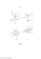
[0015] A figura 1 ilustra uma vista em perspectiva [A], uma vista lateral [B], uma vista frontal [C] e uma vista em seção lateral [D] ao longo da linha de corte AA de uma modalidade do conjunto, usando um eixo parafuso condutor com as peças em um alinhamento sem frenagem;[0015] Figure 1 illustrates a perspective view [A], a side view [B], a front view [C] and a side section view [D] along the cut line AA of an embodiment of the set, using a lead screw shaft with parts in a non-braking alignment;
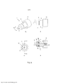
[0016] A figura 2 ilustra uma vista em perspectiva [A], uma vista lateral [B], uma vista frontal [C] e uma vista em seção lateral [D] ao longo da linha de corte AA de uma modalidade alternativa do conjunto durante uma rampa de acionamento sobre o eixo com as peças em um alinhamento de frenagem parcial;[0016] Figure 2 illustrates a perspective view [A], a side view [B], a front view [C] and a side section view [D] along the cut line AA of an alternative embodiment of the assembly during a drive ramp on the shaft with the parts in a partial braking alignment;
[0017] A figura 3 ilustra uma vista em perspectiva [A], uma vista lateral [B], uma vista frontal [C] e uma vista em seção lateral [D] ao longo da linha de corte AA de uma modalidade alternativa do conjunto usando um mecanismo de desvio;[0017] Figure 3 illustrates a perspective view [A], a side view [B], a front view [C] and a side section view [D] along the cut line AA of an alternative embodiment of the assembly using a bypass mechanism;
[0018] A figura 4 ilustra uma vista em perspectiva [A], uma vista lateral [B], uma vista frontal [C] e uma vista em seção lateral [D] ao longo da linha de corte AA de uma modalidade alternativa do conjunto usando um mecanismo de desvio alternativo;[0018] Figure 4 illustrates a perspective view [A], a side view [B], a front view [C] and a side section view [D] along the cut line AA of an alternative embodiment of the assembly using an alternative bypass mechanism;
[0019] A figura 5 ilustra uma vista em perspectiva [A], uma vista lateral [B], uma vista frontal [C] e uma vista em seção lateral [D] ao longo da linha de corte AA de uma modalidade alternativa do conjunto usando uma rampa de acionamento sobre o eixo e mecanismo de desvio com as peças em um alinhamento de frenagem parcial;[0019] Figure 5 illustrates a perspective view [A], a side view [B], a front view [C] and a side section view [D] along the cut line AA of an alternative embodiment of the set using an over-axis drive ramp and deflection mechanism with parts in a partial braking alignment;
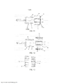
[0020] A figura 6 ilustra uma vista em perspectiva [A], uma vista lateral [B], uma vista frontal [C] e uma vista em seção lateral [D] ao longo da linha de corte AA de uma modalidade do conjunto usando um eixo de parafuso condutor e um peso com as peças em um alinhamento de frenagem parcial;[0020] Figure 6 illustrates a perspective view [A], a side view [B], a front view [C] and a side section view [D] along the AA section line of an assembly embodiment using a lead screw shaft and weight with parts in a partial braking alignment;
[0021] A figura 7 ilustra uma vista em perspectiva [A], uma vista lateral [B], uma vista frontal [C] e uma vista em seção lateral [D] ao longo da linha de corte AA de uma modalidade do conjunto usando um eixo parafuso condutor, peso e mecanismo de desvio com as peças em um alinhamento de frenagem parcial.;[0021] Figure 7 illustrates a perspective view [A], a side view [B], a front view [C] and a side section view [D] along the AA section line of an assembly embodiment using a driving screw shaft, weight and deflection mechanism with parts in a partial braking alignment.;
[0022] A figura 8 ilustra uma vista em perspectiva [A], uma vista lateral [B], uma vista frontal [C] e uma vista em seção lateral [D] ao longo da linha de corte AA de uma modalidade do conjunto usando uma rampa e arranjo de peso com as peças em um alinhamento de frenagem parcial;[0022] Figure 8 illustrates a perspective view [A], a side view [B], a front view [C] and a side section view [D] along the cut line AA of an embodiment of the assembly using a ramp and weight arrangement with parts in a partial braking alignment;
[0023] A figura 9 ilustra uma vista em perspectiva [A], uma vista lateral [B], uma vista frontal [C] e uma vista em seção lateral [D] ao longo da linha de corte AA de uma modalidade do conjunto usando uma rampa, arranjo de peso e mecanismo de desvio com as peças em um alinhamento de frenagem parcial;[0023] Figure 9 illustrates a perspective view [A], a side view [B], a front view [C] and a side section view [D] along the cut line AA of an embodiment of the assembly using a ramp, weight arrangement and deflection mechanism with parts in a partial braking alignment;
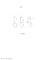
[0024] A figura 10 ilustra formas alternativas de cilindro e tubo que podem ser usadas;[0024] Figure 10 illustrates alternative cylinder and tube shapes that can be used;
[0025] A figura 11 ilustra uma vista lateral em seção transversal de um projeto de tubo e cilindro usando paredes concêntricas de diversas camadas;[0025] Figure 11 illustrates a cross-sectional side view of a tube and cylinder design using concentric multi-layer walls;
[0026] A figura 12 ilustra uma modalidade em vista lateral em seção transversal alternativa de um projeto de tubo e cilindro usando paredes concêntricas de diversas camadas com posições de magneto variáveis para aquela mostrada na figura 11; e[0026] Figure 12 illustrates an alternative cross-sectional side view embodiment of a tube and cylinder design using multi-layer concentric walls with variable magnet positions to that shown in Figure 11; and
[0027] A figura 13 ilustra outra vista lateral em seção transversal de modalidade de parede concêntrica de diversas camadas.[0027] Figure 13 illustrates another cross-sectional side view of multi-layer concentric wall modality.
[0028] Como observado acima, é descrito aqui um conjunto e métodos de uso dele para controlar ou governar a velocidade relativa de movimento entre o conjunto de peças por meio de formação de corrente de Foucault. O conjunto e métodos também podem minimizar o número de peças requerido, o que pode minimizar o número de peças móveis, aumentando com isto a durabilidade mecânica do conjunto comparada a projetos técnicos que podem ter mais peças móveis e maior complexidade de peças.[0028] As noted above, a set and methods of using it to control or govern the relative speed of movement between the set of parts by means of eddy current formation are described here. The assembly and methods can also minimize the number of parts required, which can minimize the number of moving parts, thereby increasing the mechanical durability of the assembly compared to technical designs that may have more moving parts and greater part complexity.
[0029] Para as finalidades desta especificação, o termo "cerca de" ou "aproximadamente" e variações gramaticais dele significam uma quantidade, nível, grau, valor, número, frequência, porcentagem, dimensão, tamanho, quantidade, peso, ou comprimento que varia por tanto quanto 30, 25, 20, 15, 10, 9, 8, 7, 6, 5, 4, 3, 2, ou 1% para uma quantidade de referência, nível, grau, valor, número, frequência, porcentagem, dimensão, tamanho, quantidade, peso, ou comprimento.[0029] For the purposes of this specification, the term "about" or "approximately" and grammatical variations thereof mean an amount, level, degree, value, number, frequency, percentage, dimension, size, quantity, weight, or length that varies by as much as 30, 25, 20, 15, 10, 9, 8, 7, 6, 5, 4, 3, 2, or 1% for a reference amount, level, grade, value, number, frequency, percentage , dimension, size, quantity, weight, or length.
[0030] O termo "substancialmente", ou variações gramaticais dele, se refere a no mínimo cerca de 50%, por exemplo 75%, 85%, 95%, ou 98%.[0030] The term "substantially", or grammatical variations thereof, refers to at least about 50%, for example 75%, 85%, 95%, or 98%.
[0031] O termo "compreende" e variações gramaticais dele devem ter um significado inclusivo, isto é, que ele será assumido para significar uma inclusão não somente dos componentes listados que ele referencia diretamente, mas também outros componentes ou elementos não especificados.[0031] The term "comprises" and grammatical variations thereof shall have an inclusive meaning, that is, that it will be assumed to mean an inclusion not only of the listed components that it directly references, but also other unspecified components or elements.
[0032] O termo "tubo" e variações gramaticais dele pode, em uma modalidade, se referir, a um elemento cilíndrico que tem um furo circular ou um vazio ao qual um cilindro circular corresponde, mas também poderia ser uma parede exterior quadrada de tubo e vazio circular, ou uma parede poligonal de tubo (interior e exterior) ou uma parede de tubo tronco-cônica.[0032] The term "tube" and grammatical variations thereof may, in one embodiment, refer to a cylindrical element that has a circular hole or a void to which a circular cylinder corresponds, but could also be a square outer wall of tube and circular void, or a polygonal tube wall (inside and outside) or a frusto-conical tube wall.
[0033] O termo "cilindro" e variações gramaticais dele pode se referir a diversas formas, um critério chave sendo a capacidade do cilindro mover axialmente e/ou em rotação em relação ao espaço vazio de tubo ou vice-versa, isto é, o tubo pode também mover axialmente e/ou em rotação em relação ao cilindro. Observar que o cilindro não precisa ser sólido e pode ter nele um espaço ou espaços vazios.[0033] The term "cylinder" and grammatical variations thereof can refer to various forms, a key criterion being the cylinder's ability to move axially and/or in rotation relative to the tube void space or vice versa, i.e. the tube can also move axially and/or rotationally with respect to the cylinder. Note that the cylinder does not have to be solid and can have a space or voids in it.
[0034] Em um primeiro aspecto é fornecido um conjunto que compreende: um tubo que inclui uma parede e vazio definido nele; e um cilindro que se ajusta no vazio do tubo; no qual, em uso, o cilindro e tubo têm diferentes velocidades de rotação um em relação ao outro, e no qual o tubo e cilindro, ou uma parte dele, interagem para alterar uma força de frenagem induzida por corrente de Foucault contra velocidade de movimento relativo diferente com modulação de força de frenagem surgindo devido a um equilíbrio das forças sobre o tubo e cilindro.[0034] In a first aspect, an assembly is provided that comprises: a tube that includes a wall and a void defined therein; and a cylinder that fits into the void of the tube; in which, in use, the cylinder and tube have different rotational speeds relative to each other, and in which the tube and cylinder, or a part thereof, interact to alter an eddy current-induced braking force against the speed of motion different relative with braking force modulation arising due to a balance of forces on the tube and cylinder.
[0035] Os inventores previram uma parede onde os diversos componentes interagem para alterar uma força de frenagem induzida por corrente de Foucault com modulação de força de frenagem surgindo devido a um equilíbrio das forças sobre o tubo e cilindro determinando a extensão de força aplicada.[0035] The inventors envisioned a wall where the various components interact to alter an eddy current induced braking force with braking force modulation arising due to a balance of forces on the tube and cylinder determining the extent of force applied.
[0036] O cilindro pode mover em relação ao tubo por meio de dois graus de movimento separados, que são: (a) translação axial do cilindro em relação ao tubo, de modo que o cilindro pode passar pelo menos parcialmente para dentro ou para fora do vazio do tubo; e (b) rotação do cilindro em relação ao tubo ao redor de um eixo geométrico longitudinal, o eixo geométrico passando através do vazio do tubo.[0036] The cylinder can move relative to the tube by means of two separate degrees of movement, which are: (a) axial translation of the cylinder relative to the tube, so that the cylinder can pass at least partially in or out the emptiness of the tube; and (b) rotating the cylinder relative to the tube about a longitudinal axis, the axis passing through the void of the tube.
[0037] Alternativamente, o tubo pode mover em relação ao cilindro por meio de dois graus de movimento separados, que são: (a) translação axial do tubo em relação ao cilindro, de modo que o cilindro pode passar pelo menos parcialmente para dentro ou para fora do vazio do tubo; e (b) rotação do tubo em relação ao cilindro ao redor de um eixo geométrico longitudinal, o eixo geométrico passando através do vazio do tubo.[0037] Alternatively, the tube may move relative to the cylinder by means of two separate degrees of motion, which are: (a) axial translation of the tube relative to the cylinder, so that the cylinder can pass at least partially into or out of the tube void; and (b) rotating the tube relative to the cylinder about a longitudinal axis, the axis passing through the void of the tube.
[0038] Acoplado ao tubo e cilindro pode haver um ou mais membros condutores e um ou mais membros magnéticos, o tubo e cilindro tendo, cada um, ou membros magnéticos ou membros condutores, e os membros condutores e membros magnéticos orientados para interagir uns com os outros.[0038] Coupled to the tube and cylinder may be one or more conducting members and one or more magnetic members, the tube and cylinder each having either magnetic members or conducting members, and the conducting members and magnetic members oriented to interact with each other. the others.
[0039] O tubo e cilindro podem ter um eixo geométrico comum de rotação. Como observado acima, o tubo e cilindro podem ter formas variáveis de seção transversal que não precisam ser circulares. É, contudo, antecipado que um vazio circular no tubo e seção transversal de cilindro circular correspondente deveriam fornecer o grau de eficiência máximo e daí, isto poder ser vantajoso para a maior parte de aplicações. Com duas seções transversais circulares se aninhando, um eixo geométrico comum de rotação pode ser um aspecto útil.[0039] The tube and cylinder may have a common axis of rotation. As noted above, the tube and cylinder can have variable cross-sectional shapes that need not be circular. It is, however, anticipated that a circular void in the tube and corresponding circular cylinder cross-section should provide the maximum degree of efficiency and hence, this may be advantageous for most applications. With two circular cross-sections nesting together, a common geometric axis of rotation can be a useful aspect.
[0040] O cilindro pode girar ao redor de um membro rotativo que passa através do eixo geométrico de rotação do cilindro e tubo. Um membro rotativo pode ser um eixo, embora outras configurações possam ser possíveis. Outros aspectos podem ser incluídos entre o eixo e cilindro tal como mancais. Em uma modalidade alternativa, o tubo pode girar ao redor de um membro rotativo, tal como um eixo.[0040] The cylinder can rotate around a rotating member that passes through the axis of rotation of the cylinder and tube. A rotating member can be an axis, although other configurations may be possible. Other aspects can be included between the shaft and cylinder such as bearings. In an alternative embodiment, the tube may rotate about a rotating member, such as an axle.
[0041] O membro rotativo pode incluir uma ranhura helicoidal para traduzir o movimento de rotação do membro para movimento linear do cilindro. O passo da ranhura helicoidal e/ou condutor pode ser variado para variar a resposta de freio. O membro rotativo pode ser um parafuso condutor. Uma ranhura helicoidal pode ser usada para controlar e/ou acionar movimento axial do cilindro. Isto não é essencial uma vez que outros métodos podem ser usados para controlar e acionar movimento axial, tal como diferentes arranjos de desvio, ou diferentes arranjos de face de mancal, e uma ranhura helicoidal não deveria ser vista como limitante.[0041] The rotating member may include a helical groove to translate rotational movement of the member into linear movement of the cylinder. The pitch of the helical groove and/or conductor can be varied to vary the brake response. The rotating member may be a lead screw. A helical groove can be used to control and/or drive axial movement of the cylinder. This is not essential as other methods can be used to control and drive axial movement, such as different runout arrangements, or different bearing face arrangements, and a helical groove should not be seen as limiting.
[0042] O membro ou membros condutores podem ser mais largos do que o membro ou membros magnéticos. Embora não essencial, a geração máxima de corrente de Foucault pode ocorrer quando os membros condutores são mais largos do que os membros magnéticos, de modo que um campo magnético totalmente induzido é gerado. Regiões de membro condutor menor podem ainda ser usadas, porém, um campo magnético menor pode ser gerado nestas circunstâncias, conduzindo a uma formação de arraste de corrente de Foucault reduzida.[0042] The conducting member or members may be wider than the magnetic member or members. Although not essential, maximum eddy current generation can occur when the conducting members are wider than the magnetic members, so that a fully induced magnetic field is generated. Smaller conducting member regions can still be used, however, a smaller magnetic field can be generated under these circumstances, leading to reduced eddy current drag formation.
[0043] O espaço entre os membros magnético e condutor pode ser minimizado para maximizar a força de frenagem de corrente de Foucault. Como pode ser apreciado, um espaço grande conduz a um campo magnético menor e menos geração de força de arraste de corrente de Foucault. Isto pode ser vantajoso em algumas circunstâncias, contudo, para gerar a força máxima para o esforço mínimo, um espaço substancialmente pequeno (menor do que aproximadamente 5 mm, ou 4 mm, ou 3 mm, ou 2 mm, ou menor do que 1 mm) pode ser útil.[0043] The space between the magnetic and conductor members can be minimized to maximize the eddy current braking force. As can be appreciated, a large space leads to a smaller magnetic field and less generation of eddy current drag force. This can be advantageous in some circumstances, however, to generate maximum force for minimum effort, a substantially small space (less than approximately 5 mm, or 4 mm, or 3 mm, or 2 mm, or less than 1 mm ) it might be useful.
[0044] O tubo pode ser fixado no lugar e o cilindro pode mover axialmente e em rotação em relação ao tubo. Movimento oposto pode ser útil, por exemplo, tendo o tubo movendo por meio de um motor no sentido para longe do cilindro, porém uma intenção do conjunto descrito aqui é minimizar o número global de peças requeridas e também o número de peças móveis.[0044] The tube can be fixed in place and the cylinder can move axially and in rotation with respect to the tube. Opposite movement can be useful, for example having the tube move by a motor away from the cylinder, but an intent of the assembly described here is to minimize the overall number of parts required as well as the number of moving parts.
[0045] O cilindro pode girar em uma velocidade relativa diferente ao tubo em uma direção concorrente ou em contracorrente. Como pode ser apreciado, de importância chave para gerar correntes parasitas é uma velocidade relativa de rotação diferente entre o membro condutor e o membro magnético. Um meio de conseguir isto é ter o membro condutor sendo o tubo e o membro magnético sendo o cilindro, e tendo cada membro girando em uma velocidade relativa diferente. Como observado acima, o tubo pode ser fixado no lugar e não girar de todo. O tubo pode também girar ou na mesma direção (porém em uma velocidade diferente do cilindro) ou pode girar na direção oposta ao cilindro (caso em que uma força de corrente de Foucault mais forte poderia resultar devido a uma diferença de velocidade relativa maior).[0045] The cylinder can rotate at a different relative speed to the tube in a concurrent or countercurrent direction. As can be appreciated, of key importance for generating eddy currents is a different relative speed of rotation between the conducting member and the magnetic member. One means of achieving this is to have the conducting member being the tube and the magnetic member being the cylinder, and having each member rotating at a different relative speed. As noted above, the tube can be fixed in place and not rotate at all. The tube may also rotate either in the same direction (but at a different speed than the cylinder) or it may rotate in the opposite direction to the cylinder (in which case a stronger eddy current force could result due to a greater relative speed difference).
[0046] O cilindro pode estar pelo menos parcialmente fora do tubo quando o cilindro e o tubo não estão girando. O cilindro pode estar pelo menos parcialmente dentro do tubo quando o cilindro e/ou o tubo não estão girando. Variar a posição do cilindro parcialmente quando o conjunto está em repouso pode alterar as características no início de rotação. Por exemplo, se o cilindro já está no tubo, geração imediata de força de arraste por corrente de Foucault irá ocorrer quando o cilindro ou tubo gira. Se o cilindro está fora do tubo quando começa a rotação irá ocorrer força de corrente de Foucault imediata mínima - este efeito retardado poderia ser útil quando uma pequena quantidade de rotação é desejada, tal como quando um fornecimento lento de linha é necessário em uma aplicação de subida. Quando uma queda ocorre, o fornecimento de linha se torna muito mais rápido e esta velocidade de rotação mais rápida pode então provocar engatamento do cilindro e tubo por meio de translação axial para gerar uma força de arraste e efeito de freio.[0046] The cylinder can be at least partially out of the tube when the cylinder and tube are not rotating. The cylinder may be at least partially inside the tube when the cylinder and/or tube is not rotating. Varying the cylinder position partially when the assembly is at rest can change the characteristics at the beginning of rotation. For example, if the cylinder is already in the tube, immediate generation of eddy current drag force will occur when the cylinder or tube rotates. If the cylinder is out of the tube when rotation begins, minimal immediate eddy current force will occur - this delayed effect could be useful when a small amount of rotation is desired, such as when a slow supply of line is required in an climb. When a drop occurs, the line supply becomes much faster and this faster rotation speed can then cause the cylinder and tube to engage through axial translation to generate a drag force and braking effect.
[0047] Variar a resistência do pelo menos um membro magneto e/ou posição no cilindro ou tubo, pode variar a resposta de freio. Variar a composição química do pelo menos um membro condutor e/ou posição sobre o cilindro ou tubo, pode variar a resposta de freio. Para ilustrar ainda mais este aspecto, alguns dispositivos técnicos de corrente de Foucault usam membros condutores ou magnéticos espaçados separados. O resultado disto pode ser um nível mais baixo de geração de corrente de Foucault do que um campo contínuo. Por exemplo, os membros condutores podem estar movendo em rotação para dentro e fora de um campo magnético, e daí eles podem apenas estar criando uma força de arraste de corrente de Foucault menor ou menos eficiente do que se o campo fosse contínuo. Em contraste, o arranjo descrito de um tubo e cilindro significa que pode ser possível gerar um campo contínuo entre os membros condutor e magnético devido à natureza contínua da superfície do vazio do tubo e superfície do cilindro. Um exemplo de uma relação de geração de corrente de Foucault completamente contínua pode ser ter o cilindro feito inteiramente de um membro condutor, ou pelo menos a superfície exterior do cilindro ser feita de, ou conter um membro eletricamente condutor e o próprio tubo ou superfície exterior do vazio do tubo ser feita de, ou conter um membro magnético. Uma interface contínua é então criada entre as duas peças para geração de corrente de Foucault. Variações disto podem também ser tomadas, onde uma interface menos que contínua é desejada contudo, a capacidade para criar uma superfície contínua pode ser exclusiva e uma vantagem deste projeto específico.[0047] Varying the resistance of the at least one magnet member and/or position in the cylinder or tube can vary the brake response. Varying the chemical composition of the at least one conducting member and/or position on the cylinder or tube can vary the brake response. To further illustrate this point, some technical eddy current devices use separately spaced conductive or magnetic members. The result of this can be a lower level of eddy current generation than a continuous field. For example, the conducting members may be rotating in and out of a magnetic field, and hence they may just be creating a lower or less efficient eddy current drag force than if the field were continuous. In contrast, the described arrangement of a tube and cylinder means that it may be possible to generate a continuous field between the conducting and magnetic members due to the continuous nature of the tube void surface and cylinder surface. An example of a fully continuous eddy current generating relationship might be to have the cylinder made entirely of a conductive member, or at least the outer surface of the cylinder to be made of, or contain an electrically conductive member and the tube or outer surface itself. of the void of the tube be made of, or contain a magnetic member. A continuous interface is then created between the two parts for eddy current generation. Variations of this can also be taken where a less than continuous interface is desired however the ability to create a continuous surface may be unique and an advantage of this specific design.
[0048] Variar a velocidade de rotação relativa do tubo e cilindro pode variar a resposta de freio. Como observado acima, velocidade relativa é chave na geração de correntes parasitas. Admitindo que a posição axial do cilindro e tubo não muda e o posicionamento dos membros condutor e magnético não muda, uma próxima maneira de alterar as características de corrente de Foucault pode ser mudar a velocidade relativa de rotação.[0048] Varying the relative rotational speed of the tube and cylinder can vary the brake response. As noted above, relative speed is key in generating eddy currents. Assuming that the axial position of the cylinder and tube does not change and the positioning of the conducting and magnetic members does not change, a next way to change the eddy current characteristics might be to change the relative speed of rotation.
[0049] Pelo menos parte do cilindro pode conter ou pode ser formado de material eletricamente condutor, e pode com isto formar um membro condutor. Pelo menos parte do tubo pode conter ou pode ser formada de material eletricamente condutor e pode com isto formar um membro condutor. Membros condutores podem ser colocados sobre a superfície do cilindro ou tubo e, de maneira similar, membros magnéticos podem ser colocados sobre a superfície do cilindro ou tubo. A parede do vazio do tubo ou do tubo pode, ela mesma, ser um material condutor ou magnético, como pode o próprio cilindro ou exterior do cilindro.[0049] At least part of the cylinder may contain or may be formed of electrically conductive material, and may thereby form a conductive member. At least part of the tube may contain or may be formed of electrically conductive material and may thereby form a conductive member. Conductive members may be placed on the surface of the cylinder or tube and similarly magnetic members may be placed on the surface of the cylinder or tube. The void wall of the tube or tube can itself be a conductive or magnetic material, as can the cylinder itself or the exterior of the cylinder.
[0050] Movimento axial do tubo e/ou cilindro pode ser atuado por meio de pelo menos um motor. Um motor pode ser evitado para minimizar peças e minimizar partes móveis no conjunto global embora pudesse ser incorporado, se desejado.[0050] Axial movement of the tube and/or cylinder can be actuated by at least one motor. A motor could be avoided to minimize parts and minimize moving parts in the overall assembly although it could be incorporated if desired.
[0051] O conjunto pode incluir um membro de desvio que cria uma força axial direta ou indireta sobre o tubo e/ou cilindro, deslocando o tubo e/ou cilindro juntos ou separados em rotação do tubo e/ou cilindro. O membro de desvio pode ser uma mola ou molas.[0051] The assembly may include a deflection member that creates a direct or indirect axial force on the tube and/or cylinder, displacing the tube and/or cylinder together or apart in rotation of the tube and/or cylinder. The deflection member may be a spring or springs.
[0052] Movimento axial do tubo e/ou cilindro pode ser gerado quando o tubo e/ou cilindro gira, o movimento axial provocado por uma tradução de energia centrífuga para translação axial. O tubo e/ou cilindro pode incluir no mínimo um peso deslocado do eixo geométrico de rotação que, em rotação do tubo e/ou cilindro pode estar submetido a uma força centrífuga e por meio de uma relação cinemática traduzir a força centrífuga para uma força axial sobre o tubo e/ou cilindro, com isto provocando movimento axial relativo do tubo e/ou cilindro. Uma alavanca que converte o movimento de rotação do peso para movimento axial do cilindro ou tubo, pode atuar para formar a relação cinemática. O peso ou pesos podem mover, pelo menos parcialmente, radialmente na aplicação de uma força centrífuga. Em uma modalidade alternativa, movimento centrífugo para fora do peso ou pesos pode provocar um movimento axial do cilindro, atuando sobre um arranjo de rampa.[0052] Axial movement of the tube and/or cylinder can be generated when the tube and/or cylinder rotates, the axial movement caused by a translation of centrifugal energy to axial translation. The tube and/or cylinder may include at least one weight displaced from the geometric axis of rotation which, in rotation of the tube and/or cylinder, may be subjected to a centrifugal force and, by means of a kinematic relationship, translate the centrifugal force into an axial force. on the tube and/or cylinder, thereby causing relative axial movement of the tube and/or cylinder. A lever that converts the rotational movement of the weight to axial movement of the cylinder or tube can act to form the kinematic relationship. The weight or weights can move, at least partially, radially on application of centrifugal force. In an alternative embodiment, outward centrifugal movement of the weight or weights can cause axial movement of the cylinder, acting on a ramp arrangement.
[0053] O tubo e/ou cilindro podem também ser formados como diversas camadas, o cilindro, por exemplo, tendo um interior oco e que corresponde com um tubo que tem paredes exteriores pelo menos parcialmente se estendendo sobre o exterior do cilindro, e paredes internas se estendendo para o interior do interior oco do cilindro, seja antes, durante ou depois de movimento relativo do tubo e cilindro. O tubo e cilindro podem ter diversas paredes concêntricas que se aninham. Magnetos e/ou membros condutores podem ser localizados sobre as paredes do cilindro e/ou uma ou mais das paredes exterior e/ou interior do tubo. Em outra modalidade o cilindro pode ter diversas camadas de parede concêntricas correspondendo com diversas camadas de parede concêntricas sobre o tubo, e magnetos e/ou membros condutores colocados sobre algumas ou todas as camadas de parede.[0053] The tube and/or cylinder may also be formed as several layers, the cylinder, for example, having a hollow interior and corresponding with a tube having exterior walls at least partially extending over the exterior of the cylinder, and walls internals extending into the hollow interior of the cylinder, either before, during or after relative motion of the tube and cylinder. The tube and cylinder may have several concentric walls that nest together. Magnets and/or conducting members may be located on the walls of the cylinder and/or one or more of the outer and/or inner walls of the tube. In another embodiment the cylinder may have several concentric wall layers corresponding to several concentric wall layers on the tube, and magnets and/or conductive members placed over some or all of the wall layers.
[0054] Em um segundo aspecto é fornecido um conjunto substancialmente como descrito acima, no qual o eixo geométrico e rotação do tubo e/ou cilindro são articulados a um eixo que pode, por sua vez, ser articulado a um carretel de linha e no qual o conjunto de controle de velocidade regula velocidade de fornecimento da linha a partir do carretel.[0054] In a second aspect, an assembly is provided substantially as described above, in which the geometric axis and rotation of the tube and/or cylinder are articulated to an axis that can, in turn, be articulated to a spool of line and in the which the speed control assembly regulates the speed of supplying the line from the spool.
[0055] O conjunto acima pode incluir um mecanismo de retração que retrai de volta linha fornecida sobre o carretel e uma força de fornecimento é removida.[0055] The above assembly may include a retraction mechanism that retracts the supplied line back onto the spool and a supply force is removed.
[0056] A força de frenagem aplicada para fornecimento do carretel de linha pode estar em uma velocidade substancialmente constante para extensão sobre uma faixa de torque aplicado.[0056] The braking force applied to supply the spool of thread can be at a substantially constant speed to extend over a range of applied torque.
[0057] O conjunto como descrito acima pode incluir uma carcaça, a carcaça encerrando pelo menos uma porção do conjunto. Uma carcaça pode ser útil para colocar o conjunto à prova de tempo e também para melhorar a estética do conjunto. Uma carcaça pode também ser importante para segurança, para evitar ferimento ou acidental.[0057] The assembly as described above may include a housing, the housing enclosing at least a portion of the assembly. A housing can be useful to weather-proof the assembly and also to improve the aesthetics of the assembly. A carcass can also be important for safety, to prevent injury or accidental injury.
[0058] Em um terceiro aspecto é fornecido um método de frear a queda de um objeto por meio da etapa de articular o objeto ou objetos a um carretel de linha, substancialmente como descrito acima e permitir ao objeto ou objetos caírem por meio da gravidade, criando com isto uma força de torque sobre o eixo que, por sua vez faz, com que o conjunto de controle de velocidade crie uma força de frenagem no fornecimento da linha a partir do carretel.[0058] In a third aspect there is provided a method of arresting the fall of an object by means of the step of articulating the object or objects to a spool of thread, substantially as described above and allowing the object or objects to fall by means of gravity, thereby creating a torque force on the shaft which in turn causes the speed control assembly to create a braking force on the line supply from the spool.
[0059] A força de frenagem pode também reduzir velocidade de retração da linha, suficiente para permitir que uma linha completamente estendida com nada ligado à linha, retraia de forma limpa.[0059] Braking force can also reduce line retraction speed enough to allow a fully extended line with nothing attached to the line to retract cleanly.
[0060] A faixa de torque aplicado pode cobrir objetos ligados à linha pesando cerca de 9, ou 10, ou 11, ou 12, ou 13, ou 14, ou 15, ou 20, ou 25, ou 30, ou 35, ou 40, ou 45, ou 50, ou 55, ou 60, ou 65, ou 70, ou 75, ou 80, ou 85, ou 90, ou 95, ou 100, ou 105, ou 110, ou 115, ou 120, ou 125, ou 130, ou 135, ou 140, ou 145, ou 150 kg. A faixa pode ser desde cerca de 9 kg até cerca de 150 kg.[0060] The range of applied torque may cover objects attached to the line weighing about 9, or 10, or 11, or 12, or 13, or 14, or 15, or 20, or 25, or 30, or 35, or 40, or 45, or 50, or 55, or 60, or 65, or 70, or 75, or 80, or 85, or 90, or 95, or 100, or 105, or 110, or 115, or 120, or 125, or 130, or 135, or 140, or 145, or 150 kg. The range can be from about 9 kg to about 150 kg.
[0061] Em um quarto aspecto é fornecido um dispositivo de segurança para proteção de queda, incluindo um conjunto substancialmente como descrito acima.[0061] In a fourth aspect a fall protection safety device is provided, including an assembly substantially as described above.
[0062] Em um quinto aspecto é fornecido um conjunto substancialmente como descrito acima, no qual o conjunto é incorporado em um percurso de divertimento em tirolesa para controlar a aceleração e desaceleração de uma cadeira de passageiro de tirolesa suspensa a um cabo articulado com o sistema de controle de velocidade.[0062] In a fifth aspect, an assembly is provided substantially as described above, in which the assembly is incorporated into a zipline amusement ride to control the acceleration and deceleration of a zipline passenger chair suspended from a cable articulated with the system of speed control.
[0063] Para resumir, controle ou governança da velocidade relativa dos membros que usam o dispositivo descrito pode ocorrer como para os dois exemplos A e B abaixo.[0063] To summarize, control or governance of the relative speed of members using the described device can take place as for the two examples A and B below.
[0064] A. Na modalidade de um cilindro que interage com um eixo e tubo onde: - Os dois são conectados em uma maneira na qual uma relação cinemática existe, onde rotação relativa dos dois ao longo de seu eixo geométrico é ligada a um movimento de translação relativo correspondente; - Aplicação de um torque sobre o eixo provoca a rotação do eixo, e com isto rotação do cilindro; - Rotação do cilindro resulta em formação de um torque de arraste de corrente de Foucault sobre o cilindro; e/ou - Um torque de inércia é gerado pelo cilindro devido a uma aceleração de rotação do eixo aplicada; - A relação cinemática fornece uma força axial correspondente sobre o cilindro; - Um dispositivo de desvio pode ser conectado entre o eixo e cilindro, pelo que, o desvio está em relação com a rotação relativa do eixo e cilindro, e a rotação relativa do cilindro e eixo alcança um equilíbrio onde o torque de arraste parasita e o torque de inércia são equilibrados pelo torque de reação do dispositivo de desvio; ou - Um dispositivo de desvio é conectado entre o cilindro e um corpo terra, possivelmente o tubo ou estrutura suporte, pelo que, o desvio está em relação com a translação relativa do eixo e cilindro, e a translação relativa do cilindro e eixo alcança um equilíbrio onde a força axial induzida, induzida pela conexão cinemática do torque de arraste parasita e o torque de inércia, são equilibradas pela força de reação axial do dispositivo de desvio; e - A posição de equilíbrio resultante do eixo, cilindro, e tubo fornece um torque de frenagem induzido por corrente de Foucault controlado com base na velocidade de rotação e aceleração do eixo; e - O torque induzido equilibra um torque aplicado.[0064] A. In the embodiment of a cylinder that interacts with an axis and tube where: - The two are connected in a way in which a kinematic relationship exists, where relative rotation of the two along their geometric axis is linked to a movement corresponding relative translation; - Applying a torque on the shaft causes the shaft to rotate, and thus the cylinder rotation; - Rotation of the cylinder results in the formation of an eddy current drag torque on the cylinder; and/or - An inertia torque is generated by the cylinder due to an applied shaft rotation acceleration; - The kinematic relationship provides a corresponding axial force on the cylinder; - A deflection device can be connected between the shaft and cylinder, whereby the deflection is in relation to the relative rotation of the shaft and cylinder, and the relative rotation of the cylinder and shaft reaches an equilibrium where the parasitic drag torque and the inertia torques are balanced by the reaction torque of the bypass device; or - A deflection device is connected between the cylinder and a ground body, possibly the pipe or supporting structure, whereby the deflection is in relation to the relative translation of the axis and cylinder, and the relative translation of the cylinder and axis reaches a equilibrium where the induced axial force, induced by the kinematic connection of the parasitic drag torque and the inertia torque, are balanced by the axial reaction force of the deflection device; and - The resulting balanced position of the shaft, cylinder, and tube provides a controlled eddy current-induced braking torque based on the rotational speed and acceleration of the shaft; e - The induced torque balances an applied torque.
[0065] B. Um cilindro interagindo com um eixo, onde: - Os dois são conectados em uma maneira na qual existe uma relação cinemática onde o movimento de translação relativo é permitido e um sistema centrífugo é disposto para aplicar força axial sobre o cilindro quando da rotação do eixo; e - Um dispositivo de desvio é conectado entre o cilindro e um corpo "terra" (possivelmente o tubo ou estrutura suporte), pelo que o desvio está em relação com a translação relativa do eixo e cilindro e a transação relativa do cilindro e eixo alcança um equilíbrio onde a força axial induzida de maneira centrífuga é equilibrada pela força de reação axial do dispositivo de desvio; e - A posição de equilíbrio resultante do eixo, cilindro e tubo fornece um torque de frenagem induzido por corrente de Foucault controlado com base na velocidade de rotação e a aceleração do eixo; e - O torque induzido equilibra um torque aplicado.[0065] B. A cylinder interacting with an axis, where: - The two are connected in a manner in which there is a kinematic relationship where relative translational motion is allowed and a centrifugal system is arranged to apply axial force on the cylinder when shaft rotation; and - A deflection device is connected between the cylinder and a "ground" body (possibly the pipe or supporting structure), whereby the deflection is in relation to the relative translation of the axis and cylinder and the relative transaction of cylinder and axis achieves an equilibrium where the centrifugally induced axial force is balanced by the axial reaction force of the diverter device; and - The resulting balanced position of the shaft, cylinder and tube provides controlled eddy current-induced braking torque based on rotational speed and shaft acceleration; e - The induced torque balances an applied torque.
[0066] Vantagens do conjunto acima incluem a capacidade para controlar ou governar a velocidade relativa de movimento entre as peças em uma maneira eficiente que pode também minimizar o número de peças requerido ou pode minimizar o número de peças móveis. Reduzir o número de peças móveis pode aumentar a durabilidade mecânica do conjunto, uma vez que, tipicamente, em dispositivos mecânicos, peças móveis são onde os objetos mecânicos falham ou requerem manutenção, e daí, custam mais.[0066] Advantages of the above set include the ability to control or govern the relative speed of movement between parts in an efficient manner that can either minimize the number of parts required or can minimize the number of moving parts. Reducing the number of moving parts can increase the mechanical durability of the assembly, since typically, in mechanical devices, moving parts are where mechanical objects fail or require maintenance, and hence cost more.
[0067] O conjunto e métodos de uso acima descritos são agora descritos por meio de referência a exemplos específicos.[0067] The set and methods of use described above are now described by way of reference to specific examples.
[0068] Fazendo referência às figuras 1A-1D, uma modalidade do conjunto está mostrada. O conjunto 1 como ilustrado inclui um tubo 2 com uma parede interior 3A e uma parede exterior 3B e um vazio nele. O conjunto 1 também inclui um cilindro 5. O cilindro 5 move em relação ao tubo 2 através de dois graus de movimento, sendo uma translação axial ao longo da seta A para dentro e para fora do vazio do tubo 2, e um movimento de rotação B em relação ao tubo 2. O movimento axial A pode ser completamente ou parcialmente para dentro ou para fora do vazio 4. Na modalidade ilustrada o tubo 2 e cilindro 5 compartilham um eixo geométrico de rotação central comum. O cilindro 5 pode girar na direção B ao redor de um eixo 7. O eixo 7 pode ter uma ranhura helicoidal sobre ele que quando o eixo 7 gira na direção B aciona movimento axial A do cilindro 5 em relação ao tubo 2. O tubo 2 e o cilindro 5 podem incluir um ou mais membros condutores e membros magnéticos (não mostrado). Em uma modalidade os membros condutores podem estar sobre o tubo 2 ou o próprio tubo 2 pode ser um membro condutor e os membros magnéticos podem estar sobre o cilindro 5 ou o próprio cilindro 5 pode ser um membro magnético. O cenário oposto pode também ser o caso com os membros condutores sobre o cilindro 5 ou o próprio cilindro 5 pode ser um membro condutor e os membros magnéticos podem estar sobre o tubo 2 ou o próprio tubo 2 pode ser um membro magnético. Em uso, quando o tubo 2 e cilindro 5 têm diferentes velocidades relativas de rotação, forças de arraste de correntes parasitas são produzidas entre os membros 2 e 5 resistindo à rotação quando colocados juntos em proximidade. Em uma modalidade o tubo 2 pode ser fixado em posição e o cilindro 5 gira. Quando o cilindro 5 penetra no tubo 2 forças de corrente de Foucault (não mostrado) criam uma força de arraste na rotação B do cilindro 5 e a velocidade de rotação B se reduz. Como pode ser apreciado, uma força de corrente de Foucault não necessariamente interrompe toda a rotação B, porém prende a velocidade de rotação ao nível relacionado ao campo magnético relativo produzido pelo movimento do cilindro 5 no vazio 4 do tubo 2. Movimento de rotação relativo B rápido pode resultar em uma força de frenagem forte, por exemplo. Em outras modalidades o tubo 2 pode também girar na mesma direção que o cilindro 5 (porém em uma velocidade relativa diferente) ou em uma direção de rotação contrária ao cilindro 5.[0068] Referring to Figures 1A-1D, one embodiment of the assembly is shown. Assembly 1 as illustrated includes a
[0069] Como observado acima, o eixo 7 pode ter uma ranhura helicoidal que aciona movimento axial do cilindro 5. A ranhura helicoidal pode ser uma rosca ou pode ser um parafuso condutor. O passo da ranhura helicoidal e/ou condutora pode ser variado para variar a resposta de freio. À guisa de exemplo, o passo e/ou condução pode ser tal que uma pequena rotação do eixo 7 provoca uma grande translação axial A do cilindro 5 conduzindo a uma força de frenagem rápida ser aplicada quando o cilindro 5 move rapidamente para o interior do tubo 2 e uma força de corrente de Foucault é gerada. O oposto pode também ser o caso onde passo e/ou condução é variado para somente permitir uma progressão axial A lenta resultando, portanto, em uma resposta de frenagem lenta.[0069] As noted above,
[0070] As figuras 2A até 2D ilustram uma modalidade alternativa onde movimento axial do cilindro 5 pode ser acionado por uma superfície em rampa 16 ao redor de uma interface 13 no cilindro 5. Quando o cilindro 5 gira o cilindro 5 é forçado para o vazio 4 do tubo 2. Neste exemplo nenhuma rosca helicoidal é requerida sobre o eixo 7 para acionar movimento.[0070] Figures 2A through 2D illustrate an alternative embodiment where axial movement of
[0071] As figuras 3A até 3D ilustram uma modalidade alternativa onde movimento axial do cilindro 5 pode ser influenciado também por um mecanismo de desvio tal como uma mola 8. A mola 8 pode ser usada para mudar as características da ação de frenagem. Por exemplo, a mola 8 pode ser desviada para trazer o cilindro 5 para fora do tubo 2. Quando rotação do cilindro 5 reduz de maneira suficiente, a mola 8 nesta modalidade pode atuar para trazer o cilindro 5 do tubo 2 e assim liberar a força de frenagem. Em uma modalidade alternativa a mola 8 pode ser usada ao invés disto para forçar o cilindro 5 para o interior do tubo 2 para manter uma força de frenagem por um período de tempo mais longo, ou para acelerar o ritmo no qual uma força de frenagem pode ser aplicada.[0071] Figures 3A through 3D illustrate an alternative embodiment where axial movement of
[0072] As figuras 4A até 4C ilustram outro arranjo de desvio alternativo. O cilindro 5 no conjunto 1 mostrado pode ser ligado a uma barra ou seção de cilindro fixo 18 com cada extremidade distal da seção 18 conectada a dois lados do cilindro 5 através de dois membros de desvio 23, 24. Os pontos de conexão dos membros molas sobre o cilindro 5 são desviados em relação aos pontos de conexão sobre a barra 18. Quando o cilindro 5 gira o desvio reduz ou desaparece inteiramente de maneira efetiva alongando a distância entre a barra 18 e o cilindro 5, e forçando o cilindro 5 para o interior do vazio 4. Quando a rotação B reduz ou para, os membros de desvio 23, 24 trazem o cilindro 5 de volta no sentido da barra 18 e para o desvio na posição de repouso.[0072] Figures 4A through 4C illustrate another alternative bypass arrangement. The
[0073] As figuras 5A até 5D mostram como a modalidade mostrada nas figuras 2A até 2D podem ser combinadas com um desvio tal como uma mola 8 para combinar os efeitos de ambos, um deslocamento A axial em rampa 13 e um deslocamento A axial em desvio.[0073] Figures 5A through 5D show how the embodiment shown in Figures 2A through 2D can be combined with a deflection such as a
[0074] As figuras 6A até 6D ilustram como um componente de força centrífuga pode também ser usado para mudar as características do conjunto 1. No exemplo mostrado, um peso 11 pode ser conectado ao cilindro 5. Quando o cilindro 5 gira, o peso 11 também gira, e uma força centrífuga atua sobre o peso na direção F. Por meio de uma relação cinemática a força centrífuga F sobre o peso 11 pode ser traduzida para uma força axial A sobre o cilindro 5 para empurrar ou puxar o cilindro 5 para dentro ou para fora do tubo 2. A relação cinemática pode ser por meio de um arranjo de alavanca 12. Este meio de ajustar as características pode ser útil em certas modalidades.[0074] Figures 6A through 6D illustrate how a centrifugal force component can also be used to change the characteristics of assembly 1. In the example shown, a weight 11 can be connected to
[0075] Também como mostrado nas figuras 6A até 6D, um eixo 7 pode ser ligado a um carretel de linha 9 ao qual um objeto (não mostrado) tal como uma pessoa pode ser ligado. Quando uma força é aplicada sobre a linha e carretel 9 na direção X tal como o objeto caindo devido à gravidade, a linha é fornecida a partir do carretel 9 provocando a rotação do carretel 9 e eixo 7 na direção B conduzindo o cilindro 5 a mover para ou para longe do vazio 4 do tubo 2. À guisa de exemplo, uma pessoa pode ser o objeto que cai de uma altura. Por meio da gravidade o carretel 9 gira quando linha é fornecida a partir do carretel 9. Rotação do carretel 9 provoca a rotação do eixo 7 que, por sua vez, faz com que o cilindro 5 penetre no vazio 4 do tubo 2 que pode ser fixado em posição. As diferentes velocidades de rotação do tubo 2 e cilindro 5 fazem com que ocorra uma força de arraste de corrente de Foucault (não mostrado) que com isto reduz a queda da pessoa na linha.[0075] Also as shown in figures 6A through 6D, a
[0076] As figuras 7A até 7D ilustram o mesmo arranjo centrífugo como nas figuras 6A até 6D, contudo, com a inclusão de um desvio 8 para auxiliar em trazer para dentro ou forçar para fora o cilindro 5 a partir do vazio 4 do tubo 2.[0076] Figures 7A through 7D illustrate the same centrifugal arrangement as in Figures 6A through 6D, however, with the inclusion of a
[0077] As figuras 8A até 8D ilustram um método alternativo de forçar translação axial A para o cilindro 5 utilizando ambos, força centrífuga e um método em rampa. Quando o eixo 7 gira, os pesos 15 são forçados a mover para fora na direção F, com isto atuando sobre a superfície rampa 15 do cilindro 5, provocando uma translação axial A do cilindro 5. Quando a velocidade de rotação B diminui, a força centrífuga F que atua sobre os pesos 15 diminui e o cilindro 5 retorna para uma posição não retraída.[0077] Figures 8A through 8D illustrate an alternative method of forcing axial translation A for
[0078] As figuras 9A até 9D ilustram a mesma modalidade como nas figuras 8A até 8D, onde uma mola de desvio 8 é também usada para mudar as características do movimento axial A do cilindro 5 para dentro ou para fora do vazio 4 do tubo 2.[0078] Figures 9A to 9D illustrate the same embodiment as in Figures 8A to 8D, where a
[0079] A figura 10 ilustra alguns outros arranjos alternativos do tubo 2 e cilindro 5. As modalidades descritas acima utilizam um tubo circular 2 com um vazio circular, porém o tubo 2 pode ter qualquer forma exterior poligonal tal como uma forma quadrada. A forma do vazio interior do tubo 2 pode ser circular como mostrado em figuras anteriores, poderia também ser elíptica, quadrada, hexagonal, e assim por diante. De maneira similar, figuras anteriores mostram um cilindro de seção transversal circular 5, porém o cilindro 5 pode assumir diversas formas e pode também ser oco.[0079] Figure 10 illustrates some other alternative arrangements of
[0080] Uma abordagem de parede de diversas camadas também pode ser usada.[0080] A multi-layer wall approach can also be used.
[0081] Como mostrado nas figuras 11 até 13, o cilindro 50 é oco 51, e corresponde com um tubo 60 que tem um oco complementar 61. As paredes superpostas 52, 62 do cilindro e tubo podem conter magnetos e/ou membros condutores que permitem que ocorra variação em sintonização de corrente de Foucault. As figuras 11 e 12 ilustram um tubo de diversas camadas se aninhando com um cilindro oco 50 e duas configurações de magnetos alternados 63 sobre as paredes de tubo 62. A figura 13 ilustra uma abordagem de diversas paredes 52, 62 onde ambos, tubo 60 e cilindro 50 têm paredes concêntricas múltiplas 52, 62 que correspondem juntas.[0081] As shown in figures 11 through 13,
[0082] Aspectos do conjunto e métodos de uso foram descritos à guisa de exemplo apenas, e deveria ser apreciado que modificações e adições podem ser feitas a eles sem se afastarem do escopo das reivindicações aqui.[0082] Aspects of the kit and methods of use have been described by way of example only, and it should be appreciated that modifications and additions may be made to them without departing from the scope of the claims herein.
Claims (19)
Applications Claiming Priority (3)
| Application Number | Priority Date | Filing Date | Title |
|---|---|---|---|
| NZ619034 | 2013-12-16 | ||
| NZ61903413A NZ619034A (en) | 2013-12-16 | 2013-12-16 | An assembly to control relative speed of movement between parts |
| PCT/NZ2014/000245 WO2015093983A1 (en) | 2013-12-16 | 2014-12-16 | An assembly to control or govern relative speed of movement between parts |
Publications (2)
| Publication Number | Publication Date |
|---|---|
| BR112016013700A2 BR112016013700A2 (en) | 2017-08-08 |
| BR112016013700B1 true BR112016013700B1 (en) | 2022-03-03 |
Family
ID=52706699
Family Applications (1)
| Application Number | Title | Priority Date | Filing Date |
|---|---|---|---|
| BR112016013700-0A BR112016013700B1 (en) | 2013-12-16 | 2014-12-16 | SET AND METHOD TO STOP THE FALL OF AN OBJECT |
Country Status (12)
| Country | Link |
|---|---|
| US (4) | US10300397B2 (en) |
| EP (1) | EP3084941B1 (en) |
| JP (4) | JP6581089B2 (en) |
| KR (4) | KR102547218B1 (en) |
| CN (2) | CN105993120A (en) |
| AU (4) | AU2014367356A1 (en) |
| BR (1) | BR112016013700B1 (en) |
| CA (1) | CA2933045C (en) |
| MX (2) | MX2016007849A (en) |
| NZ (1) | NZ619034A (en) |
| SG (2) | SG11201604807TA (en) |
| WO (1) | WO2015093983A1 (en) |
Families Citing this family (18)
| Publication number | Priority date | Publication date | Assignee | Title |
|---|---|---|---|---|
| NZ575464A (en) | 2009-03-10 | 2010-07-30 | Holmes Solutions Ltd | Improvements in and relating to braking mechanisms |
| NZ619034A (en) * | 2013-12-16 | 2015-03-27 | Eddy Current Ltd Partnership | An assembly to control relative speed of movement between parts |
| JP6615870B2 (en) | 2014-08-18 | 2019-12-04 | エディ・カーレント・リミテッド・パートナーシップ | Equipment, rope feeding device, passenger seat restraint device, transmission drive device, linear guide lifeline |
| SG10202004030QA (en) | 2014-08-18 | 2020-05-28 | Eddy Current Lp | Tuning of a kinematic relationship between members |
| JP6721250B2 (en) | 2014-08-18 | 2020-07-08 | エディ・カーレント・リミテッド・パートナーシップ | Latch device, rope feeding device, passenger seat restraint device, vehicle and zip line |
| CN107206977B (en) | 2014-08-20 | 2020-06-02 | 特鲁布鲁有限公司 | Eddy current braking device for linear systems |
| CN106999737B (en) | 2014-12-04 | 2021-02-26 | 涡流有限合伙公司 | Latch activation between elements |
| AU2015355674A1 (en) | 2014-12-04 | 2017-06-08 | Eddy Current Limited Partnership | Eddy current brake configurations |
| AU2015355673B2 (en) | 2014-12-04 | 2020-04-30 | Eddy Current Limited Partnership | Transmissions incorporating eddy current braking |
| CN113595358B (en) | 2014-12-04 | 2024-03-22 | 涡流有限合伙公司 | Method for modifying vortex interactions |
| SG11201704356SA (en) | 2014-12-04 | 2017-06-29 | Eddy Current Ltd Partnership | Energy absorbing apparatus |
| JP7044444B2 (en) | 2015-12-18 | 2022-03-30 | エディ・カーレント・リミテッド・パートナーシップ | Variable behavior control mechanism for power systems |
| CN106422094A (en) * | 2016-11-02 | 2017-02-22 | 上海凯悦安全消防器材有限公司 | Damping slow descent device |
| JP7022613B2 (en) * | 2018-02-14 | 2022-02-18 | 株式会社Lixil | Braking device |
| JP6996398B2 (en) * | 2018-04-06 | 2022-01-17 | 株式会社デンソー | Deburring device |
| JP6893955B2 (en) * | 2019-07-01 | 2021-06-23 | シナノケンシ株式会社 | Motor with brake |
| USD980897S1 (en) | 2021-07-30 | 2023-03-14 | Microsoft Corporation | Camera |
| USD989150S1 (en) | 2021-07-30 | 2023-06-13 | Microsoft Corporation | Camera |
Family Cites Families (193)
| Publication number | Priority date | Publication date | Assignee | Title |
|---|---|---|---|---|
| US2058024A (en) * | 1934-12-11 | 1936-10-20 | Westinghouse Air Brake Co | Eddy current brake |
| US2122315A (en) | 1936-06-11 | 1938-06-28 | Fosty Leopold | Fire escape |
| US2122312A (en) | 1937-05-25 | 1938-06-28 | Cassion John | Door attachment |
| US2437871A (en) * | 1943-02-09 | 1948-03-16 | Alfred R Wood | Magnetic coupling |
| FR925341A (en) * | 1944-06-14 | 1947-09-16 | ||
| US2409009A (en) | 1945-07-24 | 1946-10-08 | Gen Electric | One-way drive with magnetic lock |
| US2492776A (en) * | 1948-08-11 | 1949-12-27 | Martin P Winther | Dynamoelectric machine |
| GB721748A (en) | 1950-06-22 | 1955-01-12 | Baermann Max | Improvements in or relating to permanent magnet brakes or clutches |
| US2807734A (en) * | 1954-11-22 | 1957-09-24 | Control Instr Company | Torque transmitting device |
| US2771171A (en) | 1955-07-06 | 1956-11-20 | Lab Equipment Corp | Magnetically activated torque coupling |
| GB908128A (en) | 1958-06-10 | 1962-10-17 | Andre Duban | Improvements in or relating to ratchet-and-pawl devices |
| FR1418814A (en) | 1964-03-27 | 1965-11-26 | Renault | Improvements to eddy current devices for automatic control of gear changes on vehicles |
| US3447006A (en) | 1967-09-28 | 1969-05-27 | Bliss Co | Electrodynamic brake of magnetic fluid type |
| DE2032935A1 (en) | 1970-07-03 | 1972-01-13 | Kabel Metallwerke Ghh | Device for keeping the speed and tensile force of a wire running off a spool constant |
| US3868005A (en) * | 1973-03-14 | 1975-02-25 | Gen Electric | Friction clutch with centrifugal and magnetic speed control |
| DE2402748C2 (en) | 1974-01-21 | 1986-07-03 | Artur 7060 Schorndorf Föhl | Device for initiating the reel shaft blocking of an automatic seat belt retractor |
| US3962595A (en) | 1974-12-20 | 1976-06-08 | W. J. Industries, Incorporated | Magnetic particle brake |
| JPS5252800A (en) * | 1975-10-24 | 1977-04-27 | Nishi Seisakusho:Kk | Lock |
| US4036428A (en) | 1976-04-29 | 1977-07-19 | Beckman Instruments, Inc. | Fluid pressure operated eddy current brake for air driven centrifuge |
| US4093186A (en) | 1976-11-22 | 1978-06-06 | Golden Steven T | Line brake device useful for fire escape |
| GB1599300A (en) | 1977-08-27 | 1981-09-30 | Ferranti Ltd | Speed control |
| JPS585495Y2 (en) * | 1977-11-10 | 1983-01-29 | ダイワ精工株式会社 | Brake device for fishing reel |
| US4271944A (en) | 1979-02-12 | 1981-06-09 | Hanson Douglas R | Single revolution torque limiting clutch |
| US4306688A (en) | 1979-02-22 | 1981-12-22 | Injecto Mold, Inc. | Hose reel assembly |
| US4434971A (en) | 1981-02-11 | 1984-03-06 | Armco Inc. | Drilling rig drawworks hook load overspeed preventing system |
| US4561605A (en) * | 1981-12-25 | 1985-12-31 | Shimano Industrial Company Limited | Brake for a fishing reel |
| US4416430A (en) | 1982-02-01 | 1983-11-22 | Draft Systems, Inc. | Load lowering device |
| US4544111A (en) | 1982-03-09 | 1985-10-01 | Shimano Industrial Company Limited | Brake for a fishing reel |
| JPS59217589A (en) | 1983-05-26 | 1984-12-07 | 株式会社宮野鉄工所 | Slow elevator |
| US4612469A (en) | 1983-11-10 | 1986-09-16 | Kabushiki Kaisha Sankyo Seiki Seisakusho | Speed governor |
| JPS60143512A (en) | 1983-12-29 | 1985-07-29 | 株式会社日立製作所 | Method of producing superconductive member |
| JPS60259278A (en) * | 1984-06-04 | 1985-12-21 | 神鋼電機株式会社 | Falling apparatus using eddy current type brake |
| JPS6115557A (en) | 1984-06-30 | 1986-01-23 | Toshiba Corp | Levitating type conveying apparatus |
| US4957644A (en) | 1986-05-13 | 1990-09-18 | Price John T | Magnetically controllable couplings containing ferrofluids |
| JPH0356684Y2 (en) * | 1986-12-15 | 1991-12-20 | ||
| EP0312601B1 (en) | 1987-04-30 | 1991-09-18 | Tokyo-Buhin Kogyo Co., Ltd. | Eddy current brake |
| CA1315328C (en) | 1988-10-31 | 1993-03-30 | Kenji Araki | Eddy current retarder |
| US4938435A (en) | 1988-12-30 | 1990-07-03 | Frost Engineering Development Corporation | Personnel lowering device |
| KR910021550A (en) | 1990-02-02 | 1991-12-20 | 발터 쾰러 | Wire brake |
| DE4018214A1 (en) | 1990-06-07 | 1991-12-12 | Harting Elektronik Gmbh | DEVICE FOR ELECTROMAGNETICALLY OPERATING A LOCKING MECHANISM OF A BELT REEL |
| JP2523883Y2 (en) * | 1992-02-24 | 1997-01-29 | 株式会社三協精機製作所 | Governor with pulley |
| JPH05252800A (en) * | 1992-02-28 | 1993-09-28 | Fuji Oozx Kk | Control method and equipment for power transmission equipment using eddy current joint |
| US5205386A (en) | 1992-03-05 | 1993-04-27 | United Technologies Corporation | Pawl and ratchet clutch with pawl holdback |
| JP3584473B2 (en) * | 1992-04-22 | 2004-11-04 | Fdk株式会社 | Magnetic damper device |
| DE9300966U1 (en) | 1993-01-25 | 1993-03-11 | Chen, Jeff, Shyong City, Tw | |
| US5712520A (en) | 1993-05-21 | 1998-01-27 | Magna Force, Inc. | Permanent magnet braking system |
| US5477093A (en) * | 1993-05-21 | 1995-12-19 | Magna Force, Inc. | Permanent magnet coupling and transmission |
| US5396140A (en) * | 1993-05-28 | 1995-03-07 | Satcon Technology, Corp. | Parallel air gap serial flux A.C. electrical machine |
| US5636804A (en) | 1993-10-05 | 1997-06-10 | Bando Leports, Ltd. | Double-bearing fishing reel |
| WO1995016496A1 (en) | 1993-12-14 | 1995-06-22 | Strickler James H | Sport climbing safety device |
| EP0662569A1 (en) | 1994-01-10 | 1995-07-12 | Iwao Ikegami | Brake apparatus |
| CA2178838C (en) | 1994-01-13 | 2003-08-12 | Leonard John Feathers | Speed responsive coupling device especially for fall arrest apparatus |
| WO1995019204A1 (en) | 1994-01-18 | 1995-07-20 | Barrow Hepburn Sala Limited | Clutch mechanism for use in safety apparatus |
| JP2929517B2 (en) | 1994-04-01 | 1999-08-03 | ダイワ精工株式会社 | Backlash prevention device for fishing reels |
| US5441137A (en) | 1994-05-04 | 1995-08-15 | Eaton Corporation | Clutch with a centrifugally applied ball ramp actuator |
| US5862891A (en) | 1994-10-28 | 1999-01-26 | Knorr-Bremse Systeme Fur Scheinenfahrzeuge Gmbh | Electromagnetic or permanent-magnetic rail brake |
| US5862903A (en) | 1994-12-02 | 1999-01-26 | Itt Automotive Electrical Systems, Inc. | Centrifugal clutch for power door locks |
| JP3360281B2 (en) | 1995-03-15 | 2002-12-24 | 株式会社アテックス | Bale diameter variable type roll baler |
| DE29506374U1 (en) | 1995-04-13 | 1996-10-02 | Funex Ag | Amusement device |
| US5791584A (en) | 1996-01-25 | 1998-08-11 | Kuroiwa; Sachimasa | Tension control unit for filamentous material |
| JPH09275672A (en) * | 1996-04-01 | 1997-10-21 | Akebono Brake Ind Co Ltd | Eddy current type retarder |
| US5822874A (en) | 1996-04-29 | 1998-10-20 | Nemes; Anne | Automatically retracting chalk line marking tool |
| DE19618903C2 (en) | 1996-05-10 | 1998-03-19 | Knorr Bremse Systeme | Magnetic brake, especially linear eddy current brake |
| JPH1098868A (en) | 1996-09-24 | 1998-04-14 | Aichi Steel Works Ltd | Pole layout system for electromagnetic brake |
| US5779178A (en) | 1996-11-07 | 1998-07-14 | Rostra Precision Controls, Inc. | Seat belt retractor assembly having magnetically actuated locking mechanism |
| JPH10140536A (en) | 1996-11-12 | 1998-05-26 | Taisei Corp | Frame for laying underwater mat and laying method of underwater mat |
| US5711404A (en) | 1997-02-05 | 1998-01-27 | Lee; Ying-Che | Magnetic adjustable loading device with eddy current |
| US5742986A (en) | 1997-02-13 | 1998-04-28 | Trw Inc. | Seat belt buckle with hall effect locking indicator and method of use |
| US6086005A (en) | 1997-03-11 | 2000-07-11 | Daiwa Seiko, Inc. | Fishing reel with magnetic force spool rotational-speed control during spool free rotational state |
| JPH10252025A (en) | 1997-03-12 | 1998-09-22 | N D K:Kk | Self-luminescent type road rivet |
| EP0976191A1 (en) | 1997-04-14 | 2000-02-02 | David A. Zornes | Magnet coupler having enhanced electromagnetic torque |
| JPH11119680A (en) | 1997-10-20 | 1999-04-30 | Ricoh Co Ltd | Liquid crystal display device |
| JP3835014B2 (en) | 1997-10-20 | 2006-10-18 | 東亞合成株式会社 | Curable composition |
| US5928300A (en) | 1997-10-30 | 1999-07-27 | Simula Inc. | Three-axis aircraft crash sensing system |
| JP3961668B2 (en) | 1998-05-06 | 2007-08-22 | 美和ロック株式会社 | Sliding door closer |
| US6042517A (en) | 1998-09-10 | 2000-03-28 | Bell Sports, Inc. | Bicycle trainer magnetic resistance device |
| DE19859445C2 (en) | 1998-12-22 | 2001-01-11 | Asm Automation Sensorik Messte | Measuring cable displacement sensor with a longitudinal drive for the cable drum |
| DE19951221A1 (en) | 1999-04-01 | 2000-10-05 | Mannesmann Ag | Winding mechanism with housing incorporates electric motor, gear and traction roller fitted on gear output shaft, motor shaft being connected to gear input shaft |
| JP2000316272A (en) | 1999-04-27 | 2000-11-14 | Topre Corp | Maximum speed limiting device of bicycle |
| US6051897A (en) | 1999-05-05 | 2000-04-18 | Synchro-Start Products, Inc. | Solenoid actuator with positional feedback |
| JP2001017041A (en) | 1999-07-02 | 2001-01-23 | Akebono Brake Ind Co Ltd | Braking mechanism for reel supported with bearings at both ends |
| GB2352645B (en) | 1999-07-21 | 2004-01-14 | Yu-Peng Chen | Magnetic damping device for an exercising device |
| DE29912725U1 (en) | 1999-07-21 | 1999-10-07 | Chen Yu Peng | Magnetic damping device for a training device |
| GB2352784A (en) | 1999-08-04 | 2001-02-07 | Moog Inc | Energy-absorbing brake |
| GB2354645A (en) | 1999-09-27 | 2001-03-28 | Cooper Technologies Co | Low profile fuse |
| US6293376B1 (en) | 1999-11-22 | 2001-09-25 | Magnetar Technologies Ltd | Apparatus including eddy current braking system |
| US20040055836A1 (en) | 1999-11-22 | 2004-03-25 | Pribonic Edward M. | Eddy current braking apparatus with adjustable braking force |
| US20060278478A1 (en) | 1999-11-22 | 2006-12-14 | Pribonic Edward M | Eddy current braking apparatus with adjustable braking force |
| GB2357563B (en) | 1999-12-21 | 2002-04-03 | Latchways Plc | Energy absorber |
| US6533083B1 (en) | 2000-02-15 | 2003-03-18 | Magnetar Technologies, Inc | Eddy current braking apparatus |
| CA2400030A1 (en) | 2000-02-15 | 2001-08-23 | Edward M. Pribonic | Eddy current braking apparatus |
| DE20003513U1 (en) | 2000-02-28 | 2001-07-26 | Wirth Co Kg Masch Bohr | Elevator |
| AU2001273177A1 (en) | 2000-07-06 | 2002-01-21 | Rose Manufacturing Company | Controlled descent device |
| US6412611B1 (en) | 2000-07-17 | 2002-07-02 | Magnetar Technologies, Ltd | Eddy current brake system with dual use conductor fin |
| DE60141315D1 (en) | 2000-09-18 | 2010-04-01 | Isuzu Motors Ltd | Eddy current brake with a magnet consisting of an electromagnet and a permanent magnet |
| DE10196701T1 (en) | 2000-09-29 | 2003-09-04 | Jin Feng | Overrunning clutch |
| US20020162477A1 (en) | 2001-03-02 | 2002-11-07 | Emiliano Palumbo | Dual cable zipline having mechanical ascension and braking systems |
| US6764505B1 (en) | 2001-04-12 | 2004-07-20 | Advanced Cardiovascular Systems, Inc. | Variable surface area stent |
| US7014026B2 (en) | 2001-06-07 | 2006-03-21 | Drussel Wilfley Design, L.L.C. | Manual/automatic pressure control mechanism for centrifugal clutch |
| DE10149112B4 (en) | 2001-10-05 | 2004-11-25 | Robert Bosch Gmbh | Method for determining a triggering decision for restraint devices in a vehicle |
| US6698554B2 (en) * | 2001-12-21 | 2004-03-02 | Visteon Global Technologies, Inc. | Eddy current brake system |
| US6557673B1 (en) | 2001-12-21 | 2003-05-06 | Visteon Global Technologies, Inc. | Integral park brake/eddy current brake assembly |
| AU2002347122A1 (en) * | 2001-12-28 | 2003-07-15 | Suter Racing International Ag | Abseiling device used as rescue equipment in disaster situations, particularly fires in buildings or tall buildings |
| US7011607B2 (en) | 2002-01-23 | 2006-03-14 | Saris Cycling Group, Inc. | Variable magnetic resistance unit for an exercise device |
| US20050146213A1 (en) | 2002-02-28 | 2005-07-07 | Kenji Imanishi | Eddy current speed reducer |
| US6723017B2 (en) | 2002-05-09 | 2004-04-20 | Visteon Global Technologies, Inc. | Differential assembly |
| EP1401087A1 (en) * | 2002-09-20 | 2004-03-24 | Tai-Her Yang | Axially movable rotor |
| EP3358723A1 (en) | 2002-12-20 | 2018-08-08 | Tai-Her Yang | Electrical machine with structure for axially moving the rotor using centrifugal force |
| TWI298621B (en) | 2003-01-06 | 2008-07-11 | Shimano Kk | Braking device for a dual bearing reel |
| TW572477U (en) * | 2003-01-08 | 2004-01-11 | Huang-Dung Jang | Magnetic force sensing coupler |
| GB2398054B (en) | 2003-01-24 | 2005-08-03 | Ropepower Ltd | Powered rope climbing apparatus |
| WO2004073928A2 (en) | 2003-02-19 | 2004-09-02 | Archer Daniels Midland Company | Methods and composition for dust and erosion control |
| WO2004075991A2 (en) | 2003-02-21 | 2004-09-10 | Life Pack Technologies, Inc. | Apparatus for exterior evacuation from buildings |
| JP4067995B2 (en) | 2003-03-28 | 2008-03-26 | ヒタチグローバルストレージテクノロジーズネザーランドビーブイ | Rotating disk storage device and method for releasing actuator suspension assembly |
| TWM251925U (en) | 2003-08-21 | 2004-12-01 | Jung-Rung Shie | Brake structure for rolling door |
| DE102004007434A1 (en) | 2004-02-16 | 2005-09-22 | Minebea Co., Ltd. | Electric machine |
| US7294947B2 (en) * | 2004-03-01 | 2007-11-13 | Flux Drive, Inc. | Apparatus for transferring torque magnetically |
| WO2005090037A1 (en) | 2004-03-12 | 2005-09-29 | Intellipack | Hand held dispenser |
| DE102004013836A1 (en) | 2004-03-16 | 2005-10-06 | Bielomatik Leuze Gmbh + Co.Kg | Method for rotary friction welding of plastic parts and apparatus for carrying out the method |
| CN100494040C (en) | 2004-04-29 | 2009-06-03 | 特雷克斯-德马格合资有限公司 | A rope winding system for winding and unwinding steel ropes of cranes |
| US8727078B2 (en) | 2004-05-28 | 2014-05-20 | Velocity Magnetics, Inc. | Selectively incrementally actuated linear eddy current braking system |
| GB2415818B (en) | 2004-06-30 | 2008-12-31 | Autoliv Dev | Arrangement for triggering a vehicle safety device |
| JP4620404B2 (en) | 2004-08-02 | 2011-01-26 | アサヒビール株式会社 | Yeast mutant, method for producing yeast having high glutathione content, culture thereof, fraction thereof, yeast extract, and food and drink containing glutathione |
| US20100211239A1 (en) | 2004-08-06 | 2010-08-19 | Christensen Ladd E | Towrope Winch Dead Start |
| CN1783674A (en) * | 2004-11-24 | 2006-06-07 | 乐金电子(天津)电器有限公司 | Cylindrical eddy current shaft connector |
| US7018324B1 (en) | 2004-11-30 | 2006-03-28 | Lily Lin | Magnetic controlled loading device in combination of a power generating set and an adjusting drive mechanism |
| DE102005036570A1 (en) | 2004-12-16 | 2006-07-06 | Steinert Elektromagnetbau Gmbh | Method for decelerating a running metal strip and system for carrying out the method |
| GB0507806D0 (en) | 2005-04-19 | 2005-05-25 | Bm Engineering Uk Ltd | Belay device |
| US8079569B2 (en) | 2005-04-29 | 2011-12-20 | Gerald Lesko | Cable drawworks for a drilling rig |
| US20070001048A1 (en) | 2005-05-18 | 2007-01-04 | Wooster Peter C | Descent device |
| EP1915273A2 (en) | 2005-06-30 | 2008-04-30 | Magnetar Technologies Corporation | Axial rotary eddy current brake with adjustable braking force |
| DE102005032694A1 (en) | 2005-07-13 | 2007-01-18 | Forhouse Corp., Shenkang | Magnetic brake controller e.g. for exercising equipment, fastened on flywheel of unit, and has base, rotation device, which rotates on base and which has several connecting sections provided |
| GB2432140A (en) | 2005-11-15 | 2007-05-16 | Latchways Plc | Fall arrest safety device |
| US20070135561A1 (en) | 2005-12-08 | 2007-06-14 | Christian Rath | Method of dust abatement |
| JP2007276540A (en) | 2006-04-03 | 2007-10-25 | Honda Motor Co Ltd | Occupant restraint system for vehicle |
| US7367869B2 (en) | 2006-05-02 | 2008-05-06 | U.S. Technology Corporation | Method of masking and a hot melt adhesive for use therewith |
| US7528514B2 (en) | 2006-06-22 | 2009-05-05 | International Business Machines Corporation | Centrifugal magnetic clutch |
| WO2008008225A2 (en) | 2006-07-10 | 2008-01-17 | Sigma Industries, Llc | Retractable lifeline safety device |
| US20080074223A1 (en) | 2006-09-22 | 2008-03-27 | Pribonic Edward M | Reinforcing of permanent magnet arrays |
| US7984796B2 (en) | 2006-10-13 | 2011-07-26 | Magnetar Technologies Corp. | Motion retarding system and method |
| US7843349B2 (en) | 2006-11-03 | 2010-11-30 | D B Industries, Inc. | Retrofittable radio frequency identification connector |
| US20080105503A1 (en) | 2006-11-08 | 2008-05-08 | Pribonic Edward M | Axial rotary eddy current brake with self-adjustable braking force |
| GB2451799B (en) | 2007-05-16 | 2011-12-14 | Latchways Plc | Safety device |
| PL2175851T3 (en) | 2007-07-12 | 2013-11-29 | Oral Health Australia Pty Ltd | Biofilm treatment |
| TW200920438A (en) | 2007-07-18 | 2009-05-16 | Stone S Throw Llc | Personal escape device and methods for using same |
| US8893854B2 (en) | 2007-09-28 | 2014-11-25 | D B Industries, Llc | Retractable lifeline assembly |
| WO2009047469A1 (en) | 2007-10-12 | 2009-04-16 | Latchways Plc | Rotational energy absorber and fall arrest system |
| CA2646073C (en) | 2007-12-10 | 2011-02-01 | Rapid Egress Descent Systems Ltd. | Descent control device |
| US9016432B2 (en) | 2007-12-10 | 2015-04-28 | Rapid Egress Descent Systems Ltd. | Descent control device |
| JP5122273B2 (en) | 2007-12-28 | 2013-01-16 | 株式会社シマノ | Spool braking device for double-bearing reel |
| EP2249927B1 (en) | 2008-02-27 | 2011-12-28 | Rapid Vertical Egress System Holding B.v. | Rescue arrangement |
| CN101559267A (en) | 2008-04-18 | 2009-10-21 | 陈锦鹏 | Device and system for preventing falling |
| US8847464B2 (en) * | 2008-06-12 | 2014-09-30 | General Electric Company | Electrical machine with improved stator flux pattern across a rotor that permits higher torque density |
| US10001804B2 (en) | 2008-08-11 | 2018-06-19 | Force Dimension S.A.R.L. | Force-feedback device and method |
| US20100112224A1 (en) | 2008-10-30 | 2010-05-06 | James A Lott | Methods and formulations for protection ans dust control involving bulk material |
| US20100116922A1 (en) | 2008-11-13 | 2010-05-13 | Reliance Industries, Llc | Cable reel lock for fall arrestor |
| NZ575464A (en) | 2009-03-10 | 2010-07-30 | Holmes Solutions Ltd | Improvements in and relating to braking mechanisms |
| RU106462U1 (en) * | 2009-09-15 | 2011-07-10 | Государственное образовательное учреждение высшего профессионального образования "Уфимский государственный авиационный технический университет" | SLOW INDUCTION BRAKE |
| CN102099988B (en) | 2009-10-09 | 2013-04-10 | 丰田自动车株式会社 | Dynamo-electric machine |
| US8226024B2 (en) | 2009-10-14 | 2012-07-24 | D B Industries, Inc. | Self-retracting lifeline with reserve lifeline portion |
| US8556234B2 (en) | 2009-11-13 | 2013-10-15 | Ride Inc. | Single cable descent control device |
| CN104667444B (en) | 2009-12-23 | 2021-04-27 | D B工业股份有限公司 | Fall protection safety device with brake mechanism |
| US20110174914A1 (en) | 2010-01-20 | 2011-07-21 | Gimmal Co., Ltd. | Connector device to prevent person from falling |
| GB201002854D0 (en) * | 2010-02-19 | 2010-04-07 | Wavefront Reservoir Technologies Ltd | Magnet - operated pulsing tool |
| US20110240403A1 (en) | 2010-03-31 | 2011-10-06 | D B Industries, Inc. | Lifeline Connector for Use with Self-Retracting Lifeline with Disconnectable Lifeline |
| EP2377783A1 (en) | 2010-04-14 | 2011-10-19 | Interroll Holding AG | Transport roller with centrifugally actuated magnetic brake |
| US9199103B2 (en) | 2010-05-12 | 2015-12-01 | Msa Technology, Llc | Fall protection arrangement |
| CN102893505B (en) * | 2010-05-17 | 2015-05-20 | 日立金属株式会社 | Coupling device |
| US8469149B2 (en) | 2010-06-07 | 2013-06-25 | D B Industries, Llc | Self-retracting lifeline with disconnectable lifeline |
| US8800715B2 (en) * | 2010-11-17 | 2014-08-12 | Reliance Industries, Llc | Retractable fall arrest with component assembly and cantilevered main shaft |
| US8424460B2 (en) | 2010-12-28 | 2013-04-23 | Shawn Geoffrey LERNER | Trolley for downhill zip line thrill ride |
| WO2013003402A2 (en) | 2011-06-29 | 2013-01-03 | Key Safety Systems, Inc. | Fall arrester |
| CN202203305U (en) | 2011-08-01 | 2012-04-25 | 台州市黄岩华阳机电科技有限公司 | Centrifugal clutch and electric car gear-shifting drive hub with the same |
| CN103814232B (en) | 2011-09-27 | 2016-12-21 | 纳博特斯克有限公司 | The speed restraining device of vehicle and the vehicle with speed restraining device |
| US9033115B2 (en) * | 2011-11-11 | 2015-05-19 | Shawn Lerner | Zip line braking |
| US8601951B2 (en) | 2011-11-11 | 2013-12-10 | Shawn Lerner | Self-cooling trolley |
| CN102497085A (en) | 2011-12-23 | 2012-06-13 | 浙江大学 | Permanent-magnet eddy current retarder based on Halbach array |
| US8857578B2 (en) | 2012-01-19 | 2014-10-14 | Technical Film Systems, Inc. | Magnetic brake |
| DE102012202553A1 (en) | 2012-02-20 | 2013-08-22 | Carl Zeiss Smt Gmbh | LITHOGRAPHY DEVICE WITH DAMPING DEVICE |
| CN102627063B (en) | 2012-03-05 | 2014-05-28 | 江苏大学 | Real-time control device and real-time control method for motion direction of electromagnetic energy-regeneration semi-active suspension |
| US20140110947A1 (en) | 2012-10-24 | 2014-04-24 | Vestas Wind Systems A/S | Wind turbine generator having an eddy current brake, wind turbine having such a generator, and associated methods |
| CN103127627B (en) | 2013-01-30 | 2015-07-08 | 黄柏源 | Double-brake round-trip-controllable descent control device |
| CN103244577A (en) | 2013-04-27 | 2013-08-14 | 上海法诺格绿色能源系统有限公司 | Overrunning clutch |
| CN103326538B (en) * | 2013-06-25 | 2016-01-20 | 常州市博能节能科技有限公司 | Permanent magnet intelligent speed-regulating energy-saving device |
| NZ619034A (en) * | 2013-12-16 | 2015-03-27 | Eddy Current Ltd Partnership | An assembly to control relative speed of movement between parts |
| US10046745B2 (en) | 2014-03-20 | 2018-08-14 | TruBlue LLC | Cable-traversing trolley adapted for use with impact braking |
| JP6721250B2 (en) | 2014-08-18 | 2020-07-08 | エディ・カーレント・リミテッド・パートナーシップ | Latch device, rope feeding device, passenger seat restraint device, vehicle and zip line |
| SG10202004030QA (en) | 2014-08-18 | 2020-05-28 | Eddy Current Lp | Tuning of a kinematic relationship between members |
| JP6615870B2 (en) | 2014-08-18 | 2019-12-04 | エディ・カーレント・リミテッド・パートナーシップ | Equipment, rope feeding device, passenger seat restraint device, transmission drive device, linear guide lifeline |
| CN106999737B (en) | 2014-12-04 | 2021-02-26 | 涡流有限合伙公司 | Latch activation between elements |
| CN106887940A (en) | 2016-06-13 | 2017-06-23 | 裴承华 | A kind of self-cooled permanent-magnet eddy current Flexible Transmission speed regulator |
| US9723823B2 (en) | 2016-08-29 | 2017-08-08 | Terry Richardson | Fishing line dispenser |
| WO2019161256A2 (en) * | 2018-02-15 | 2019-08-22 | The Charles Stark Draper Laboratory, Inc. | Electrostatic motor |
-
2013
- 2013-12-16 NZ NZ61903413A patent/NZ619034A/en unknown
-
2014
- 2014-12-16 KR KR1020227019061A patent/KR102547218B1/en active IP Right Grant
- 2014-12-16 JP JP2016538788A patent/JP6581089B2/en active Active
- 2014-12-16 KR KR1020217033498A patent/KR102409249B1/en active IP Right Grant
- 2014-12-16 CN CN201480075517.5A patent/CN105993120A/en active Pending
- 2014-12-16 AU AU2014367356A patent/AU2014367356A1/en not_active Abandoned
- 2014-12-16 EP EP14872681.3A patent/EP3084941B1/en active Active
- 2014-12-16 SG SG11201604807TA patent/SG11201604807TA/en unknown
- 2014-12-16 KR KR1020167017695A patent/KR102316382B1/en active IP Right Grant
- 2014-12-16 WO PCT/NZ2014/000245 patent/WO2015093983A1/en active Application Filing
- 2014-12-16 BR BR112016013700-0A patent/BR112016013700B1/en active IP Right Grant
- 2014-12-16 KR KR1020237020782A patent/KR20230093549A/en not_active Application Discontinuation
- 2014-12-16 SG SG10201805077SA patent/SG10201805077SA/en unknown
- 2014-12-16 CA CA2933045A patent/CA2933045C/en active Active
- 2014-12-16 MX MX2016007849A patent/MX2016007849A/en active IP Right Grant
- 2014-12-16 CN CN202111254914.7A patent/CN114301259A/en active Pending
- 2014-12-16 US US15/104,949 patent/US10300397B2/en active Active
-
2016
- 2016-06-15 MX MX2020011623A patent/MX2020011623A/en unknown
-
2019
- 2019-02-26 AU AU2019201311A patent/AU2019201311B2/en active Active
- 2019-04-08 US US16/378,463 patent/US10603596B2/en active Active
- 2019-08-29 JP JP2019156868A patent/JP6962977B2/en active Active
-
2020
- 2020-02-24 US US16/799,339 patent/US11266917B2/en active Active
-
2021
- 2021-06-23 AU AU2021204270A patent/AU2021204270B2/en active Active
- 2021-10-14 JP JP2021168761A patent/JP7184993B2/en active Active
-
2022
- 2022-02-17 US US17/651,521 patent/US11628373B2/en active Active
- 2022-08-15 AU AU2022218456A patent/AU2022218456A1/en active Pending
- 2022-11-24 JP JP2022187386A patent/JP7381166B2/en active Active
Also Published As
Similar Documents
| Publication | Publication Date | Title |
|---|---|---|
| BR112016013700B1 (en) | SET AND METHOD TO STOP THE FALL OF AN OBJECT | |
| US20210367498A1 (en) | Eddy current brake configurations | |
| BR112017003208B1 (en) | DEVICE, LINE DISPENSING DEVICE, PASSENGER SEAT CONTAINMENT, TRANSMISSION DRIVE AND LINEAR GUIDED LIFELINE | |
| BR112017003080B1 (en) | LOCKING DEVICES | |
| JP2017505094A5 (en) | ||
| JP2023164785A (en) | Zip line trolley or carriage including transmission mechanism incorporating eddy current braking | |
| BR112017010692B1 (en) | Activation coupling between elements |
Legal Events
| Date | Code | Title | Description |
|---|---|---|---|
| B06U | Preliminary requirement: requests with searches performed by other patent offices: procedure suspended [chapter 6.21 patent gazette] | ||
| B09A | Decision: intention to grant [chapter 9.1 patent gazette] | ||
| B16A | Patent or certificate of addition of invention granted [chapter 16.1 patent gazette] |
Free format text: PRAZO DE VALIDADE: 20 (VINTE) ANOS CONTADOS A PARTIR DE 16/12/2014, OBSERVADAS AS CONDICOES LEGAIS. |