EP0662569A1 - Brake apparatus - Google Patents
Brake apparatus Download PDFInfo
- Publication number
- EP0662569A1 EP0662569A1 EP94300151A EP94300151A EP0662569A1 EP 0662569 A1 EP0662569 A1 EP 0662569A1 EP 94300151 A EP94300151 A EP 94300151A EP 94300151 A EP94300151 A EP 94300151A EP 0662569 A1 EP0662569 A1 EP 0662569A1
- Authority
- EP
- European Patent Office
- Prior art keywords
- magnet row
- moving
- row
- magnet
- stationary
- Prior art date
- Legal status (The legal status is an assumption and is not a legal conclusion. Google has not performed a legal analysis and makes no representation as to the accuracy of the status listed.)
- Withdrawn
Links
Images


Classifications
-
- H—ELECTRICITY
- H02—GENERATION; CONVERSION OR DISTRIBUTION OF ELECTRIC POWER
- H02K—DYNAMO-ELECTRIC MACHINES
- H02K49/00—Dynamo-electric clutches; Dynamo-electric brakes
- H02K49/10—Dynamo-electric clutches; Dynamo-electric brakes of the permanent-magnet type
-
- F—MECHANICAL ENGINEERING; LIGHTING; HEATING; WEAPONS; BLASTING
- F16—ENGINEERING ELEMENTS AND UNITS; GENERAL MEASURES FOR PRODUCING AND MAINTAINING EFFECTIVE FUNCTIONING OF MACHINES OR INSTALLATIONS; THERMAL INSULATION IN GENERAL
- F16D—COUPLINGS FOR TRANSMITTING ROTATION; CLUTCHES; BRAKES
- F16D63/00—Brakes not otherwise provided for; Brakes combining more than one of the types of groups F16D49/00 - F16D61/00
-
- F—MECHANICAL ENGINEERING; LIGHTING; HEATING; WEAPONS; BLASTING
- F16—ENGINEERING ELEMENTS AND UNITS; GENERAL MEASURES FOR PRODUCING AND MAINTAINING EFFECTIVE FUNCTIONING OF MACHINES OR INSTALLATIONS; THERMAL INSULATION IN GENERAL
- F16D—COUPLINGS FOR TRANSMITTING ROTATION; CLUTCHES; BRAKES
- F16D2129/00—Type of operation source for auxiliary mechanisms
- F16D2129/06—Electric or magnetic
- F16D2129/065—Permanent magnets
Definitions
- This invention relates to a brake apparatus used in various vehicles, cargo machines such as cranes, and various other machinery instruments for decelerating or stopping a moving member or suppressing excessive acceleration thereof.
- Current commonly used brake apparatus include a moving member, a stationary member, and a hydraulic or electromagnetic means for pressing a brake member (e.g., brake pad) from the stationary member to a part (e.g., brake shoe) of the moving member whereby mechanical friction or sliding resistance exerts a braking force to the moving member.
- Brake apparatus utilizing the viscosity resistance of fluid are also used in some applications.
- brake apparatus of the power generator type using electromagnets are also used in some applications.
- brake apparatus of the power generator type using electromagnets are also used in some applications.
- brake apparatus of the power generator type using electromagnets are also used in some applications.
- brake apparatus of the power generator type using electromagnets are also used in some applications.
- brake apparatus of the power generator type using electromagnets are also used in some applications.
- brake apparatus using permanent magnets instead of electromagnets are known as retarders which are used as subordinate brake apparatus in large size automobiles such as buses and trailers.
- a permanent magnet generates a
- the above-mentioned brake apparatus relying on mechanical friction have the problem that the frictional members and the surrounding components must be heat resistant because upon braking, the kinetic energy the moving member possesses is converted into heat energy locally at frictional areas to invite a local temperature rise. Wear of the frictional members due to friction is also a problem. Thermal influence is sometimes exerted to the surrounding equipment.
- the brake apparatus utilizing the viscosity resistance of fluid the kinetic energy the moving member possesses is converted into heat energy which appears as a temperature rise of the fluid. At the elevated temperature, the fluid lowers its viscosity resistance to reduce the braking force. To avoid this inconvenience, an extra device for circulating or cooling the fluid is necessary.
- the brake apparatus of the power generator type using electromagnetic force and the brake apparatus using permanent magnets as retarders allow for generation of induction current which is converted into heat energy through Joule effect to invite a local temperature rise at the rotor or the like. Then a cooling device or heat dissipating fins must be added.
- an object of the present invention is to provide a novel and improved brake apparatus which avoids local temperature rise, allows for use of less heat resistant parts, and eliminates a need for cooling.
- the present invention relates to a brake apparatus including a stationary member and a moving member adapted to move along a predetermined motion orbit relative to the stationary member.
- the brake apparatus applies a braking force from the stationary member to the moving member.
- the stationary member carries thereon a row of at least one magnet, which may be either a permanent magnet or an electromagnet, such that a plurality of magnetic poles are arranged along the orbit of the moving member.
- the moving member carries thereon a row of at least one permanent magnet such that a plurality of magnetic poles are arranged along the orbit of the moving member and such that the plurality of magnetic poles are opposed to the magnetic poles of the magnet row on the stationary member when the moving member moves.
- At least one magnet row of the magnet row on the stationary member and the magnet row on the moving member, on its side facing the other magnet row, has magnetic poles of opposite sign alternately arranged in the direction of the orbit.
- Either one magnet row of the magnet row on the stationary member and the magnet row on the moving member is fixedly secured to the member carrying it.
- the other magnet row or each magnet therein is coupled to the member carrying it through an intermediate holding means or selective interlocking means.
- the other magnet row or each magnet When a magnetic attractive force and/or a magnetic repulsive force between the magnetic poles of the other magnet row and the magnetic poles of the one magnet row acts in a direction to accelerate motion of the moving member, the other magnet row or each magnet is allowed for movement relative to the member carrying it in a direction including the direction of the magnetic attractive force and/or magnetic repulsive force acting.
- a magnetic attractive force and/or a magnetic repulsive force between the magnetic poles of the other magnet row and the magnetic poles of the one magnet row acts in a direction to decelerate motion of the moving member, the other magnet row or each magnet is restrained from movement relative to the member carrying it in a direction including the direction of the magnetic attractive force and/or magnetic repulsive force acting.
- the selective interlocking means includes a unidirectional motion transmitting mechanism interposed between the other magnet row and the member carrying it.
- the selective interlocking means has each magnet of the other magnet row held such that each magnet is individually movable and includes a restraint edge for restraining movement of each magnet such that each magnet cannot move beyond a predetermined position.
- the magnet row on the moving member side (often referred to as a moving side magnet row) is fixedly secured to the moving member and the magnet row on the stationary member side (often referred to as a stationary side magnet row) is fixedly secured to the stationary member.
- At least one row of the moving side magnet row and the stationary side magnet row is such that magnetic poles of opposite sign in one magnet row are alternately arranged on the side facing the other magnet row and in the direction of the motion orbit.
- the respective magnetic poles in the moving side magnet row come in facing relationship or alignment with the respective magnetic poles in the stationary side magnet row sequentially one by one.
- a state of magnetic poles of same sign facing each other and a state of magnetic poles of opposite sign facing each other occur alternately.
- magnetic attractive/repulsive forces act in a direction to decelerate the moving member while the moving member moves from the state that the moving and stationary side magnets face each other between magnetic poles of opposite sign to the state that the moving and stationary side magnets face each other between magnetic poles of identical sign.
- magnetic attractive/repulsive forces act in a direction to accelerate the moving member while the moving member moves from the state that the moving and stationary side magnets face each other between magnetic poles of identical sign to the state that the moving and stationary side magnets face each other between magnetic poles of opposite sign.
- the moving member moves forward, the state that magnetic attractive/repulsive forces between the magnetic poles on the moving member side and the magnetic poles on the stationary member side act in a direction to accelerate the moving member and the state that magnetic attractive/repulsive forces act in a direction to decelerate the moving member occur alternately.
- the moving member is once decelerated and immediately thereafter accelerated.
- the overall process results in no braking force acting on the moving member in total.
- the brake apparatus of the present invention is constructed such that among the moving side magnet row and the stationary side magnet row, either one magnet row is fixedly secured to the member carrying it (the moving or stationary member), and the other magnet row is held to the member carrying it (the stationary or moving member) via a selective interlocking means which selectively allows or restrains movement of the same member.
- the selective interlocking means does not allow magnetic attractive/repulsive forces to act in a direction to accelerate the moving member, but allows magnetic attractive/repulsive forces to act only in a direction to decelerate the moving member, thereby applying braking force to the moving member.
- the selective interlocking or intermediate holding means holds the other magnet row or magnets therein such that when magnetic attractive/repulsive forces between the magnetic poles of the other magnet row and the magnetic poles of the one magnet row acts in a direction to accelerate motion of the moving member, the other magnet row or magnets therein is allowed for movement relative to the member carrying it in a direction including the direction of the magnetic attractive/repulsive forces acting. Then in this state, the other magnet row or magnets therein makes relative movement due to the magnetic attractive/repulsive forces to thereby absorb the forces. As a result, it is avoided that the moving member is accelerated by the magnetic attractive/repulsive forces.
- the selective interlocking means holds the other magnet row or magnets therein such that when magnetic attractive/repulsive forces between the magnetic poles of the other magnet row and the magnetic poles of the one magnet row acts in a direction to decelerate motion of the moving member, the other magnet row or magnets therein is restrained from movement relative to the member carrying it in a direction including the direction of the magnetic attractive/repulsive forces acting. Then in this state, the magnetic attractive/repulsive forces are transmitted to the moving member as a decelerating force through the other magnet row or magnets therein, thereby applying brake to the moving member.
- braking force is applied to the moving member by the magnetic attractive/repulsive forces between magnets.
- the braking force is analyzed from the standpoint of energy.
- magnets on the moving member side make non-elastic collision against magnets on the stationary member side.
- the kinetic energy of the moving member is converted into potential energy whereby the moving member is braked while the thus accumulated potential energy is dissipated as molecular energy through internal deformation on the stationary member side caused by the non-elastic collision.
- at least a portion of the molecular energy is dissipated as heat energy.
- the molecular energy is created as internal energy in the interior of the stationary side magnets, stationary member holding the magnets, and members supporting the stationary member, this heat energy on release is spread over a very wide area or many components. Then the quantity of heat energy generated per unit area is small enough to minimize the risk of local temperature rise. As opposed to conventional brakes of the friction type wherein heat is locally generated at frictional portions which become hot, the present invention eliminates the risk of heating the components hot by local temperature rise.
- FIG. 1 is a partially cut-away front elevation of a brake according to one embodiment of the invention.
- FIG. 2 is a side view of a magnet row on the moving member side and a magnet row on the stationary member side in the brake of FIG. 1.
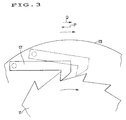
- FIG. 3 is an enlarged view looking in the direction of an arrow III in FIG. 1 of a ratchet and a pawl in the brake of FIG. 1.
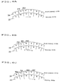
- FIG. 4 schematically illustrates the relationship between the moving and stationary side magnet rows at sequential stages for describing the operation of the brake of FIG. 1.
- FIG. 5 is a view corresponding to FIG. 4A and illustrating a modification of the embodiment of FIG. 1.
- FIG. 6 is a partially cut-away front elevation of a modified brake embodiment similar to FIG. 1, with the unidirectional motion transmitting mechanism attached to the stationary side.
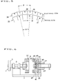
- FIG. 7 is a front elevation of a brake according to another embodiment of the invention.
- FIG. 8 is a plan view of the brake of FIG. 7.
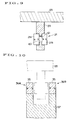
- FIG. 9 is an enlarged cross section taken along lines IX-IX in FIG. 7.
- FIG. 10 is an enlarged cross section taken along lines X-X in FIG. 7.
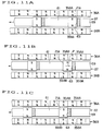
- FIG. 11 schematically illustrates the relationship between the moving and stationary side magnet rows at sequential stages for describing the braking operation of the brake of FIG. 7.
- FIG. 12 schematically illustrates the relationship between the moving and stationary side magnet rows at sequential stages for describing the non-braking operation of the brake of FIG. 7.
- FIG. 13 illustrates a modification of the embodiment of FIG. 7 by showing the relationship between the moving and stationary side magnet rows.
- FIG. 14 illustrates another modification of the embodiment of FIG. 7 by showing the relationship between the moving and stationary side magnet rows.
- FIG. 15 illustrates a further modification of the embodiment of FIG. 7 by showing the relationship between the moving and stationary side magnet rows.
- FIG. 16 illustrates a still further modification of the embodiment of FIG. 7 by showing the relationship between the moving and stationary side magnet rows.
- FIG. 17 illustrates a still further modification of the embodiment of FIG. 7 by showing the relationship between the moving and stationary side magnet rows.
- FIG. 18 illustrates a still further modification of the embodiment of FIG. 7 wherein the stationary side magnets are slidable by showing the relationship between the moving and stationary side magnet rows.
- FIG. 19 illustrates a still further modification of the embodiment of FIG. 7 wherein the stationary side magnets are rotatable, showing the relationship between the moving and stationary side magnet rows at sequential stages for describing the operation of the brake.
- FIG. 20 is a partially cut-away front elevation of a brake according to a further embodiment of the invention.
- FIG. 21 is a perspective view of a moving side magnet row used in the brake of FIG. 20.
- FIG. 22 is a perspective view of a stationary side magnet row used in the brake of FIG. 20.
- FIGS. 1 to 4 there is schematically illustrated one embodiment of the brake apparatus according to the present invention wherein the motion of the moving member is rotation and the selective interlocking means includes a unidirectional motion transmitting mechanism.
- the brake apparatus shown in FIGS. 1 to 4 includes a moving member or rotor 1 and a stationary member 23.
- the rotor 1 includes a rotating member 3 mounted on a rotating shaft 5 which is supported for rotation by a frame 7 via bearings 9.
- the rotating member 3 is a subject to be braked, for example, a wheel or axle of various vehicles or a roller of various apparatus and installations (e.g., a roller for feeding wire, rod or sheet material).
- a ratchet 11 Secured to the rotating shaft 5 is a ratchet 11.
- an interlocking rotary wheel 13 is mounted via a bearing 15 for rotation relative to the rotating shaft 5.
- the interlocking wheel 13 has a ratchet pawl 17 protruding from one side thereof and adapted to engage with the ratchet 11.
- a row 22 of permanent magnets 21 is carried on the other side of the interlocking wheel 13 through a yoke 19 of a magnetic material. As shown in FIG.
- this permanent magnet row 22 (to be referred to as a moving side permanent magnet row, hereinafter) includes a plurality of permanent magnets 21 which are disposed at an equal angle circumferentially about the rotational center axis O of the rotating shaft 5 (or the interlocking wheel 13) in an annular array such that N and S poles are alternately arranged.
- a translatable disk or carriage 25 Opposed to the moving side permanent magnet row 22 on the interlocking wheel 13 is a translatable disk or carriage 25 forming a part of the stationary member 23.
- the disk 25 has a diameter approximately equal to that of the interlocking wheel 13.
- the translatable disk 25 has a plurality of slide shafts 27 extending outward (rightward in FIG. 1) and parallel to the rotational axis O of the rotating shaft 5.
- the slide shafts 27 are extended through support rings 29 in the frame 7 for sliding motion.
- a drive mechanism 31 in the form of a hydraulic cylinder, for example, is attached to the frame 7 and coupled to the central slide shaft 27.
- the disk 25 is translated toward and away from the interlocking wheel 13 by means of the drive mechanism 31.
- a row 36 of permanent magnets 35 is carried on the translatable disk 25 through a yoke 33 of a magnetic material so that the row 36 faces the moving side permanent magnet row 22.
- this permanent magnet row 36 (to be referred to as a stationary side permanent magnet row, hereinafter) includes a plurality of permanent magnets 35 which are disposed at an equal angle circumferentially about the rotational axis O of the rotating shaft 5 in an annular array such that N and S poles are alternately arranged as shown in FIG. 2.
- the angle between the adjacent magnetic poles in the moving side permanent magnet row 22 with respect to the rotational axis O is equal to the angle between the adjacent magnetic poles in the stationary side permanent magnet row 36.
- FIGS. 1 and 2 The operation of the embodiment shown in FIGS. 1 and 2 is described with reference to FIGS. 3 and 4. It is assumed that the rotating element 3 rotates in a direction shown by solid arrows in FIGS. 3 and 4.
- the drive mechanism 31 is actuated to move the translatable disk 25 forward to place the stationary side permanent magnet row 36 in the vicinity of the moving side permanent magnet row 22 to provide magnetic interaction therebetween as shown in phantom lines in FIG. 1.
- the rotating member 3 or moving side permanent magnet row 22 rotates, there alternately occur an attractive state that the respective magnetic poles of one sign in the moving side permanent magnet row 22 are aligned with the magnetic poles of reverse sign in the stationary side permanent magnet row 36 and a repulsive state that the respective magnetic poles of one sign in the moving side permanent magnet row 22 are aligned with the magnetic poles of the same sign in the stationary side permanent magnet row 36.
- the moving side permanent magnet row 22 rotates in the solid line arrow direction from the state of FIG. 4A that magnetic poles of opposite sign are in alignment to the state of FIG. 4C that magnetic poles of the same sign are in alignment through the state of FIG. 4B.
- the N pole of the moving side permanent magnet 21A receives a force opposite to the rotational direction, that is, a decelerating force as shown by broken line arrow P in FIG. 3 and FIG. 4B as a result of a magnetic attractive force from S pole of the stationary side permanent magnet 35A aligned therewith and a magnetic repulsive force to N pole of the adjacent stationary side permanent magnet 35B.
- the interlocking wheel 13 is thus decelerated against rotation.
- the pawl 17 comes in engagement with the ratchet 11 as shown by solid lines in FIG. 3, the ratchet 11 and the rotating member 3 coupled thereto through the rotating shaft 5 are also decelerated. That is, a braking force is applied to the rotating member 3.
- the moving side permanent magnet row 22 rotates in the solid line arrow direction from the state of FIG. 4C that magnetic poles of the same sign are in alignment to the state of FIG. 4E that magnetic poles of opposite sign are in alignment through the state of FIG. 4D.
- the N pole of the moving side permanent magnet 21A receives a magnetic repulsive force from the N pole of the stationary side permanent magnet 35B and a magnetic attractive force from the S pole of the adjacent stationary side permanent magnet 35C. That is, the N pole of the moving side permanent magnet 21A receives a force in the rotational direction, that is, an accelerating force as shown by a broken line arrow Q in FIG. 3 and FIG. 4D.
- the magnetic poles of the moving side permanent magnet raw 22 receive the resultant of magnetic attractive/repulsive forces in a decelerating direction so that rotation of the interlocking wheel 13 is decelerated and the ratchet pawl 17 engages with the ratchet 11, applying a braking force to the rotating member 3.
- the unidirectional motion transmitting function of the ratchet 11 and pawl 17 ensures that the resultant of magnetic attractive/repulsive forces between the magnetic poles of the moving and stationary sides is not transmitted to the rotating member when it acts in an accelerating direction, and the resultant is transmitted to the rotating member when it acts in a decelerating direction, applying a braking force to the rotating member 3. Therefore, in this embodiment, the ratchet 11, pawl 17 and interlocking wheel 13 form the selective interlocking means 41 whereas the ratchet 11 and pawl 17 form the unidirectional motion transmitting mechanism 43.
- each of the moving side permanent magnet row 22 on the interlocking wheel 13 and the stationary side permanent magnet row 36 on the translatable disk 25 includes magnetic poles of opposite sign alternately arranged in a rotational direction although it is possible that only one permanent magnet row includes alternately arranged magnetic poles of opposite sign and the other permanent magnet row includes an arrangement of magnetic poles of the same sign.
- FIG. 5 One example of this latter embodiment is shown in FIG. 5 in which the stationary side permanent magnet row 36 includes an alternate arrangement of magnetic poles of opposite sign N and S and the moving side permanent magnet row 22 includes an arrangement of magnetic poles of the same sign N.
- the angle between the centers of two adjacent magnetic poles associated with the permanent magnet row consisting of an arrangement of same magnetic poles is equal to the angle between the centers of every second magnetic poles associated with the permanent magnet row consisting of an arrangement of opposite magnetic poles. More specifically in the embodiment of FIG. 5, the angle ⁇ between the centers of two adjacent magnetic poles N associated with the moving side permanent magnet row 22 is equal to the angle ⁇ between the centers of two adjacent S poles (or two adjacent N poles) associated with the stationary side permanent magnet row 36.
- a ratchet mechanism is used as the unidirectional motion transmitting mechanism in the embodiment of FIGS. 1 to 4, a unidirectional clutch such as a unidirectional roller clutch may also be used.
- the unidirectional motion transmitting mechanism is provided on the moving side although it may be provided on the stationary side.
- This embodiment is shown in FIG. 6 wherein the translatable disk 25 on the stationary side is provided with a ratchet 45.
- An interlocking rotary disk 47 similar to the interlocking rotary wheel is mounted for rotation to the translatable disk 25.
- the interlocking disk 47 is provided with a ratchet pawl 49 adapted to engage with the ratchet 45.
- the stationary side permanent magnet row 36 is fixedly secured to the interlocking disk 47.
- the moving side permanent magnet row 22 is fixedly secured to a wheel which is fixedly secured to the rotating shaft 5 so that the permanent magnet row 22 always rotates with the rotating member 3.
- the ratchet 45 and pawl 49 are combined for selective engagement to provide a directional function as described below.
- the resultant of magnetic attractive/repulsive forces between the magnetic poles of the stationary side permanent magnet row 36 and the magnetic poles of the moving side permanent magnet row 22 acts in a direction to accelerate the moving side
- the ratchet 45 and pawl 49 function to allow the stationary side interlocking disk 47 to rotate in the direction of the magnetic attractive/repulsive forces acting, that is, in a direction to absorb the accelerating force to the moving side.
- FIGS. 7 to 10 illustrate another embodiment of the braking apparatus according to the present invention wherein the moving member 1 makes linear motion and the selective interlocking means 41 has each magnet of the moving side magnet row held such that each magnet is individually movable and includes a restraint edge for restraining movement of each magnet such that each magnet cannot move beyond a predetermined position.
- the moving member 1 in this embodiment is a vehicle truck 55 having wheels 53 which travels along a pair of linear rails 51.
- a stationary member 23 is a longitudinally extending stationary base 57 fixedly disposed at a predetermined position between the pair of rails 51.
- Two parallel spaced apart rows of permanent magnets 36A and 36B are fixedly secured to the stationary base 57 along the travel direction of the vehicle truck 55.
- a plurality of permanent magnets 35 are arranged such that N and S poles in each row are alternately arranged at the inside surface in the longitudinal direction (which is the travel direction of the vehicle truck 55), and the poles of one sign on one side are aligned with the poles of opposite sign on the other side, that is, N and S poles in row 36A are aligned with and opposed to S and N poles in row 36B, respectively.
- a frame 59 which can pass between the two stationary side permanent magnet rows 36A and 36B.
- each moving side permanent magnet 21 includes a pair of permanent magnet segments 21a and 21b connected by a yoke 62 of magnetic material such that magnetic poles of opposite sign N and S are positioned at opposed outer sides.
- the spacing between the slots 61 is determined such that the distance L1 between the rearward edges 63 of the two adjacent slots which are rearward in the travel direction of the vehicle truck 55 (to be referred to as restraint edges, hereinafter) is four times the distance L2 between the centers of the magnetic poles of two adjacent permanent magnets 35 in the stationary side permanent magnet rows 36A and 36B.
- the magnetic pole orientation N-S is identical for all the moving side permanent magnets 21.
- FIGS. 7 to 10 The operation of the embodiment of FIGS. 7 to 10 is described with reference to FIGS. 11 and 12.
- the truck 55 moves forward and the moving side permanent magnet row 22 reaches the position between the permanent magnet rows 36A and 36B of the stationary base 57.
- a braking force is applied to the truck 55 as follows. First, the situation changes from the state that S and N poles of a permanent magnet 21A of the moving side permanent magnet row 22 on opposite sides face the N pole of a permanent magnet 35AA of the stationary side permanent magnet row 36A and the S pole of a permanent magnet 35BA of the stationary side permanent magnet row 36B, respectively, as shown in FIG.
- FIG. 11A that is, the moving side permanent magnet 21A faces the stationary side permanent magnets 35AA and 35BA each between their magnetic poles of opposite sign
- FIG. 11C that is, the moving side permanent magnet 21A faces the stationary side permanent magnets 35AB and 35BB each between their magnetic poles of same sign
- magnetic attractive forces act between the magnetic poles of the moving side permanent magnet 21A and the stationary side permanent magnets 35AA and 35BA, and magnetic repulsive forces act between the magnetic poles of the moving side permanent magnet 21A and the stationary side permanent magnets 35AB and 35BB.
- These magnetic attractive/repulsive forces cooperatively act in a direction against the forward movement of the truck 55 as shown by a broken line arrow P in FIG. 11B, that is, in a direction to decelerate motion of the truck 55.
- the restraint edge 63 of the slot 61 in the frame 59 causes the moving side permanent magnet 21A to move forward together with the frame 59 against the magnetic attractive/repulsive forces while the magnetic attractive/repulsive forces act on the frame 59 and hence, the truck 55 as a braking force.
- transition state shown in FIGS. 11A to 11C and the transition state shown in FIGS. 12A to 12C are alternately repeated while a braking force is applied to the truck 55 only during the transition state shown in FIGS. 11A to 11C.
- the distance L1 between the restraint edges 63 of a pair of adjoining slots 61 is four times the center-to-center distance L2 between two adjoining magnetic poles in the stationary side permanent magnet rows 36A and 36B, that is, the stationary side includes four magnets 35 per one permanent magnet 21 on the moving side.
- the present invention is not limited to this embodiment.
- the distance L1 between the restraint edges 63 of a pair of adjoining slots 61 may be at least two times the center-to-center distance L2 between two adjoining magnetic poles in the stationary side permanent magnet rows 36A and 36B.
- FIGS. 13 and 15 show the restraint edge distance L1 greater than the magnetic pole center distance L2 on the stationary side permanent magnet rows 36A and 36B by a factor of 3.
- FIGS. 14 and 16 show the restraint edge distance L1 greater than the magnetic pole center distance L2 on the stationary side permanent magnet rows 36A and 36B by a factor of 2.
- the slot 61 must have a length (L5 in FIG. 14, for example) enough to allow the moving side permanent magnet 21 to slide from a position aligned with a pair of permanent magnets in the stationary side permanent magnet rows 36A and 36B to a next position aligned with an adjacent pair of permanent magnets.
- the distance L1 between the restraint edges 63 of a pair of adjoining slots 61 is an odd multiple of the center-to-center distance L2 between two adjoining magnetic poles in the stationary side permanent magnet rows 36A and 36B
- the situation is reversed from the foregoing embodiment using an even multiple.
- the restraint edge distance L1 is a three multiple of the magnetic pole center distance L2 in the stationary side permanent magnet rows 36A and 36B
- the magnetic poles of the moving side permanent magnets 21 are alternately oriented in the moving direction as in the embodiment of FIG. 13, states wherein all the moving side permanent magnets 21 apply braking forces and states wherein all the moving side permanent magnets 21 apply no braking forces occur alternately.
- the above-mentioned relationship can be further extended.
- the distance L1 between the restraint edges 63 of a pair of adjoining slots 61 is more than two times and a non-integral multiple of the center-to-center distance L2 between two adjoining magnetic poles in the stationary side permanent magnet rows 36A and 36B, for example, greater by a non-integral multiple of 2.1 or 2.3, the moving side permanent magnets 21 are aligned with the magnetic poles in the stationary side permanent magnet rows 36A and 36B at different points of time, and as a result, the moving side permanent magnets 21 apply braking forces at different points of time. That is, the timing of applying braking force is shifted among the magnets.
- FIG. 17 One exemplary arrangement of permanent magnets is illustrated in FIG. 17.
- substantially equal results are obtained whether the orientation of magnetic poles of the moving side permanent magnets 21 is identical or alternately reversed in a moving direction.
- FIGS. 7 to 17 the moving and stationary sides are in an interchangeable relationship. It is then possible that permanent magnets are held for sliding motion on the stationary side and permanent magnets are fixedly held on the moving side.
- FIG. 18 One exemplary arrangement is illustrated in FIG. 18 which otherwise corresponds to the embodiment of FIG. 17.
- slots 61 are formed in a stationary base 57 (see FIG. 7) and have opposed edges. One of the edges which is located forward in the moving direction of the truck 55 forms a restraint edge 63.
- a stationary side permanent magnet 35 is fitted in each of the slots 61 for sliding motion.
- Two stationary side rows 36A and 36B include such arrangements of permanent magnets 35. The manner of mounting the stationary side permanent magnets 35 may be the same as that of the moving side permanent magnets shown in FIG. 9.
- a moving side row 22 includes a plurality of permanent magnets 21 which are fixedly secured to the frame 59 of the vehicle truck 55 (see FIG. 7).
- braking forces are applied when the stationary side permanent magnets 35 are restrained from further movement by the forward restraint edges 63 of the slots 61. No accelerating forces are applied since the stationary side permanent magnets 35 escape by sliding along the slots 61 aft in the moving direction.
- FIGS. 13 to 16 can be modified such that the stationary side permanent magnets 35 are slidable as in FIG. 18.
- the clearance means for allowing the moving or stationary side permanent magnets to escape when magnetic attractive/repulsive forces act between the magnetic poles of the stationary and moving sides in an accelerating direction, such that the magnetic attractive/repulsive forces do not act on the vehicle truck 55 is not limited to the embodiments of FIGS. 7 to 17 wherein the permanent magnets are linearly slid in a direction along the moving direction of the truck 55. It suffices that the direction along which the moving or stationary side permanent magnets escape includes a component parallel to the moving direction of the truck 55.
- One alternative is a means for providing escape for the moving or stationary side permanent magnets by rotating or turning them.
- a moving side row 22 includes alternately arranged permanent magnets 21 which are fixedly secured to a frame 59 of a vehicle truck 55 (see FIG. 7).
- Two stationary side rows 36A and 36B include permanent magnets 35 which are mounted on vertical pivots 71 anchored to a stationary base 57 (see FIG. 7) such that the magnets 35 may rotate about the pivots 71 in a horizontal plane.
- Stops 73 and 75 are disposed on opposite sides of each stationary side permanent magnet 35 and symmetrically with respect to the pivot 71 and have restraint edges 63 for restraining one of the magnetic poles of the permanent magnet from rotating forward in the moving direction of the row 22 from the position directly facing the magnetic pole of a moving side permanent magnet 21.
- each stationary side permanent magnet 35 is axially aligned with a moving side permanent magnet 21 in the row 22 in a transverse direction with their magnetic poles of opposite sign faced each other.
- First magnetic attractive forces act between stationary side permanent magnets 35AA and 35BA and a moving side permanent magnet 21A, for example, and then magnetic repulsive forces act between the stationary side permanent magnets 35AA and 35BA and the following moving side permanent magnet 21B.
- the moving side permanent magnet row 22 moves further forward from this situation to a situation as shown in FIG. 19C wherein magnetic repulsive forces act between the stationary side permanent magnets 35AA and 35BA and the moving side permanent magnet 21B to rotate the stationary side permanent magnets 35AA and 35BA aft in the moving direction (counter-clockwise and clockwise, respectively).
- the magnetic poles or tips of the stationary side permanent magnets 35AA and 35BA are moved apart from the moving side permanent magnet 21B. This avoids the same magnetic repulsive forces from acting as an accelerating force on the moving side permanent magnet row 22.
- the stationary side permanent magnets 35 are rotatable in the embodiment of FIG. 19, it is possible that the stationary side permanent magnets 35 are fixed and the moving side permanent magnets 21 are rotatable because of the simple interchangeable relationship between the stationary and moving sides as previously mentioned.
- the arrangement of FIG. 19A is modified such that the permanent magnets designated at 21 are stationary side ones and the permanent magnets designated at 35 are moving side ones.
- the positional relationship or correspondence between the stationary and moving side permanent magnets may also be modified as previously mentioned for the embodiments of FIGS. 7 to 18. For example, smoother braking force can be obtained by modifying the arrangement of FIG.
- FIGS. 7 to 19 have referred to a vehicle truck as a typical example of the linearly moving member to be braked although the present invention is applicable to any other form of the linearly moving member.
- FIGS. 7 to 19 are also applicable when the moving member is a rotational motion member.
- a rotational motion member is provided with a plurality of slots extending circumferentially about the center of rotation of the member, and a moving side permanent magnet is held in each slot for sliding motion.
- a plurality of permanent magnets are held on a rotational motion member such that the permanent magnets may independently rotate about axes parallel to the center of rotation of the member, and a permanent magnet row on the stationary member includes permanent magnets fixedly arranged circumferentially about the center of rotation of the rotational motion member.
- a stationary member is provided with a plurality of slots extending circumferentially about the center of rotation of a rotational member, and a permanent magnet is held in each slot for sliding motion.
- a plurality of permanent magnets are held on a stationary member such that the permanent magnets may independently rotate about axes parallel to the center of rotation of a rotational member, and a permanent magnet row on the rotational member includes permanent magnets fixedly arranged circumferentially about the center of rotation of the rotational member.
- FIGS. 20 to 22 A still further embodiment of the present invention is illustrated in FIGS. 20 to 22. Like the embodiment of FIGS. 1 to 4, this embodiment includes a moving member which makes rotational motion and a unidirectional motion transmitting mechanism. This embodiment is different from that of FIGS. 1 to 4 in that it exerts a variable braking force.
- FIGS. 20 to 22 on a rotating shaft 5 coupled to a rotating member (not shown) as a moving member, a plurality of axially arranged support disks 83 are mounted through unidirectional roller clutches 81.
- a moving side permanent magnet row 22 in the form of a magnet ring is fitted around each support disk 83 at its outer perimeter.
- the moving side permanent magnet row 22 in the form of an alternately magnetized magnet ring is shown in FIG. 21 as a ring made of ferrite magnet or the like which is magnetized at intervals so as to have magnetic poles of opposite sign (N and S) alternately arranged circumferentially on the outer perimeter.
- the moving side includes five rows of magnets in the illustrated embodiment.
- a linear guide in the form of a straight rail 87 rests on a stationary platform 85.
- a cup-shaped carriage 89 is mounted on the linear guide 87 such that the carriage 89 may slide in a longitudinal direction of the guide.
- a screw shaft 91 is mounted in a frame to extend in alignment with the rotating shaft 5 and at an aft end coupled to a rotational drive 93 such as a servo motor via a gear train 95.
- the screw shaft 91 is extended through the side wall of the carriage 89. Since the screw shaft 91 and the carriage 89 are in thread engagement, the carriage 89 can be moved back and forth in a direction parallel to the center axis of the rotating shaft 5 by actuating the drive 95 to rotate the screw shaft 91 via the gears 95.
- the carriage 89 is configured as a closed end hollow cylinder having a center axis aligned with the rotating shaft 5.
- a stationary side permanent magnet row 36 in the form of a magnet ring is fitted in the inner surface of the cylinder 89.
- the stationary side permanent magnet row 36 in the form of an alternately magnetized magnet ring is shown in FIG. 22 as a ring made of ferrite magnet or the like which is magnetized at intervals so as to have magnetic poles of opposite sign (N and S) alternately arranged circumferentially on the inner surface.
- the magnet ring or stationary side permanent magnet row 36 has an inner diameter which is slightly larger than the outer diameter of the magnet ring or moving side permanent magnet row 22.
- the rotational drive 93 is actuated to rotate the screw shaft 91 to move forward the carriage 89 until the annular stationary side permanent magnet row 36 at the inner surface surrounds the annular moving side permanent magnet rows 22 at the outer surface.
- the number of moving side permanent magnet rows 22 that are surrounded by the annular stationary side permanent magnet row 36 can be varied.
- magnetic attractive and repulsive forces are sequentially exerted with rotation of the moving side permanent magnet rows 22 in the same manner as described for the embodiment of FIGS. 1 to 4.
- the braking force has been described as varying in terms of the number of moving side permanent magnet rows 22 that are surrounded by the annular stationary side permanent magnet row 36, the braking force can also be finely adjusted in terms of the overlapping surface area between the moving side permanent magnet rows 22 and the stationary side permanent magnet row 36 which also changes with the extent of projection of the carriage 89.
- FIGS. 20 to 22 wherein a plurality of annular moving side permanent magnet rows 22 are independently mounted on the rotating shaft 5 through unidirectional roller clutches 81, if magnetic poles are phase shifted among the respective moving side permanent magnet rows 22, that is, if magnetic pole centers are offset among the respective rows 22, braking forces are applied to the respective moving side permanent magnet rows 22 at different points of time. As a result, smooth braking forces are applied in total.
- braking force can be adjusted by controlling the projection of the carriage 89 to alter the overlapping area between the stationary and moving side permanent magnets.
- the moving side permanent magnet rows 22 on their outer periphery are enclosed by the stationary side permanent magnet row 36 in the embodiment of FIG. 20, it is possible that the stationary side permanent magnet row on their outer periphery are enclosed by the moving side permanent magnet row by using the alternately magnetized annular permanent magnet shown in FIG. 21 as a stationary side permanent magnet row and the alternately magnetized annular permanent magnet shown in FIG. 22 as a moving side permanent magnet row.
- the unidirectional roller clutch 81 forms a unidirectional motion transmitting mechanism in the embodiment of FIGS. 20 to 22
- a ratchet-pawl combination as shown in the embodiment of FIGS. 1 to 4 may be used instead of the clutch.
- a further modification of the embodiment of FIGS. 20 to 22 is possible.
- the moving side permanent magnet row is fixedly secured to the moving member and the stationary side permanent magnet row is held for unidirectional rotation to the stationary member through a unidirectional clutch or ratchet-pawl engagement.
- all the stationary and moving side magnet rows consist of permanent magnets. It will be understood that the stationary side magnet row may consist of electromagnets if desired.
- the brake apparatus of the invention applies a braking force to a moving member by utilizing magnetic attractive/repulsive forces between moving and stationary side magnets.
- the kinetic energy of the moving member is dissipated as molecular energy by internal deformation of the stationary side magnets, stationary member, and members supporting them, and at least a portion of this molecular energy is dissipated as heat energy. Since this heat energy on release is dispersed over a very wide area or many components, the quantity of heat energy dissipated per unit area is small enough to minimize the risk of local temperature rise. There is little likelihood of heating the components hot. Therefore the components can be made of low cost, less heat resistant materials and remain durable. There is no need for an extra cooling device or heat sink or heat radiating fins. Thermal influence to the ambient atmosphere is minimal.
Abstract
A brake apparatus applies a braking force from a stationary member (23) to a moving member (1) adapted to move relative to the stationary member (23). Magnets (35) are arranged on the stationary member (23) along the linear motion or rotational direction of the moving member (1) and magnets (21) are arranged on the moving member (1) so that the stationary side magnets (35) face the moving side magnets (21). When magnetic attractive/repulsive forces between the magnets (21,35) on the moving and stationary members act in a direction to accelerate the moving member (1), the magnets (21,35) on either one side are allowed to escape in the same direction. When magnetic attractive/repulsive forces act in a direction to decelerate the moving member (1), the magnets (21,35) are restrained from the movement in the same direction. This brake avoids any temperature rise due to local heat generation during braking.
Description
- This invention relates to a brake apparatus used in various vehicles, cargo machines such as cranes, and various other machinery instruments for decelerating or stopping a moving member or suppressing excessive acceleration thereof.
- Current commonly used brake apparatus include a moving member, a stationary member, and a hydraulic or electromagnetic means for pressing a brake member (e.g., brake pad) from the stationary member to a part (e.g., brake shoe) of the moving member whereby mechanical friction or sliding resistance exerts a braking force to the moving member. Brake apparatus utilizing the viscosity resistance of fluid are also used in some applications. Also known are brake apparatus of the power generator type using electromagnets. In addition, brake apparatus using permanent magnets instead of electromagnets are known as retarders which are used as subordinate brake apparatus in large size automobiles such as buses and trailers. In the last mentioned apparatus, a permanent magnet generates a magnetic flux across which a rotor made of conductor extends whereby eddy current is generated, thereby applying to the rotor an electromagnetic resistance force against its rotational direction.
- The above-mentioned brake apparatus relying on mechanical friction have the problem that the frictional members and the surrounding components must be heat resistant because upon braking, the kinetic energy the moving member possesses is converted into heat energy locally at frictional areas to invite a local temperature rise. Wear of the frictional members due to friction is also a problem. Thermal influence is sometimes exerted to the surrounding equipment. In the brake apparatus utilizing the viscosity resistance of fluid, the kinetic energy the moving member possesses is converted into heat energy which appears as a temperature rise of the fluid. At the elevated temperature, the fluid lowers its viscosity resistance to reduce the braking force. To avoid this inconvenience, an extra device for circulating or cooling the fluid is necessary. The brake apparatus of the power generator type using electromagnetic force and the brake apparatus using permanent magnets as retarders allow for generation of induction current which is converted into heat energy through Joule effect to invite a local temperature rise at the rotor or the like. Then a cooling device or heat dissipating fins must be added.
- Therefore, an object of the present invention is to provide a novel and improved brake apparatus which avoids local temperature rise, allows for use of less heat resistant parts, and eliminates a need for cooling.
- The present invention relates to a brake apparatus including a stationary member and a moving member adapted to move along a predetermined motion orbit relative to the stationary member. The brake apparatus applies a braking force from the stationary member to the moving member. The stationary member carries thereon a row of at least one magnet, which may be either a permanent magnet or an electromagnet, such that a plurality of magnetic poles are arranged along the orbit of the moving member. The moving member carries thereon a row of at least one permanent magnet such that a plurality of magnetic poles are arranged along the orbit of the moving member and such that the plurality of magnetic poles are opposed to the magnetic poles of the magnet row on the stationary member when the moving member moves. At least one magnet row of the magnet row on the stationary member and the magnet row on the moving member, on its side facing the other magnet row, has magnetic poles of opposite sign alternately arranged in the direction of the orbit. Either one magnet row of the magnet row on the stationary member and the magnet row on the moving member is fixedly secured to the member carrying it. The other magnet row or each magnet therein is coupled to the member carrying it through an intermediate holding means or selective interlocking means. When a magnetic attractive force and/or a magnetic repulsive force between the magnetic poles of the other magnet row and the magnetic poles of the one magnet row acts in a direction to accelerate motion of the moving member, the other magnet row or each magnet is allowed for movement relative to the member carrying it in a direction including the direction of the magnetic attractive force and/or magnetic repulsive force acting. When a magnetic attractive force and/or a magnetic repulsive force between the magnetic poles of the other magnet row and the magnetic poles of the one magnet row acts in a direction to decelerate motion of the moving member, the other magnet row or each magnet is restrained from movement relative to the member carrying it in a direction including the direction of the magnetic attractive force and/or magnetic repulsive force acting.
- Preferably, the selective interlocking means includes a unidirectional motion transmitting mechanism interposed between the other magnet row and the member carrying it.
- Preferably, the selective interlocking means has each magnet of the other magnet row held such that each magnet is individually movable and includes a restraint edge for restraining movement of each magnet such that each magnet cannot move beyond a predetermined position.
- For ease of understanding, it is assumed, apart from the present invention, that the magnet row on the moving member side (often referred to as a moving side magnet row) is fixedly secured to the moving member and the magnet row on the stationary member side (often referred to as a stationary side magnet row) is fixedly secured to the stationary member.
- At least one row of the moving side magnet row and the stationary side magnet row is such that magnetic poles of opposite sign in one magnet row are alternately arranged on the side facing the other magnet row and in the direction of the motion orbit. When the moving member moves along the orbit, the respective magnetic poles in the moving side magnet row come in facing relationship or alignment with the respective magnetic poles in the stationary side magnet row sequentially one by one. During this process, between the respective magnetic poles in the moving side magnet row and the respective magnetic poles in the stationary side magnet row, a state of magnetic poles of same sign facing each other and a state of magnetic poles of opposite sign facing each other occur alternately.
- When the moving member moves forward in the moving direction from the state that the moving and stationary side magnets face each other between magnetic poles of opposite sign, the magnetic poles of one sign on the moving member side are moved apart from the magnetic poles of other sign on the stationary member side. At this point, magnetic attractive forces between these magnetic poles of opposite sign act in a direction to prevent movement of the moving member, that is, in a direction to decelerate the moving member. Next comes a state that the moving and stationary side magnets face each other between magnetic poles of identical sign. Immediately before this state, the magnetic poles on the moving member side approach the magnetic poles of the same sign on the stationary member side and magnetic repulsive forces therebetween act in a direction to prevent movement of the moving member, that is, in a direction to decelerate the moving member. After the moving and stationary side magnets have faced each other between magnetic poles of identical sign, another situation follows. As the moving member moves further forward in the moving direction, the magnetic poles of identical sign are moved apart, and magnetic repulsive forces therebetween act in a direction to accelerate movement of the moving member. Next comes a state that the moving and stationary side magnets face each other between magnetic poles of opposite sign. Immediately before this state, the magnetic poles of one sign on the moving member side approach the magnetic poles of other sign on the stationary member side and magnetic attractive forces therebetween act in a direction to accelerate the moving member.
- Ultimately, magnetic attractive/repulsive forces act in a direction to decelerate the moving member while the moving member moves from the state that the moving and stationary side magnets face each other between magnetic poles of opposite sign to the state that the moving and stationary side magnets face each other between magnetic poles of identical sign. And magnetic attractive/repulsive forces act in a direction to accelerate the moving member while the moving member moves from the state that the moving and stationary side magnets face each other between magnetic poles of identical sign to the state that the moving and stationary side magnets face each other between magnetic poles of opposite sign. Therefore, as the moving member moves forward, the state that magnetic attractive/repulsive forces between the magnetic poles on the moving member side and the magnetic poles on the stationary member side act in a direction to accelerate the moving member and the state that magnetic attractive/repulsive forces act in a direction to decelerate the moving member occur alternately. In this case, the moving member is once decelerated and immediately thereafter accelerated. The overall process results in no braking force acting on the moving member in total.
- In contrast, the brake apparatus of the present invention is constructed such that among the moving side magnet row and the stationary side magnet row, either one magnet row is fixedly secured to the member carrying it (the moving or stationary member), and the other magnet row is held to the member carrying it (the stationary or moving member) via a selective interlocking means which selectively allows or restrains movement of the same member. The selective interlocking means does not allow magnetic attractive/repulsive forces to act in a direction to accelerate the moving member, but allows magnetic attractive/repulsive forces to act only in a direction to decelerate the moving member, thereby applying braking force to the moving member.
- Namely, the selective interlocking or intermediate holding means holds the other magnet row or magnets therein such that when magnetic attractive/repulsive forces between the magnetic poles of the other magnet row and the magnetic poles of the one magnet row acts in a direction to accelerate motion of the moving member, the other magnet row or magnets therein is allowed for movement relative to the member carrying it in a direction including the direction of the magnetic attractive/repulsive forces acting. Then in this state, the other magnet row or magnets therein makes relative movement due to the magnetic attractive/repulsive forces to thereby absorb the forces. As a result, it is avoided that the moving member is accelerated by the magnetic attractive/repulsive forces. Also the selective interlocking means holds the other magnet row or magnets therein such that when magnetic attractive/repulsive forces between the magnetic poles of the other magnet row and the magnetic poles of the one magnet row acts in a direction to decelerate motion of the moving member, the other magnet row or magnets therein is restrained from movement relative to the member carrying it in a direction including the direction of the magnetic attractive/repulsive forces acting. Then in this state, the magnetic attractive/repulsive forces are transmitted to the moving member as a decelerating force through the other magnet row or magnets therein, thereby applying brake to the moving member.
- In this way, braking force is applied to the moving member by the magnetic attractive/repulsive forces between magnets. The braking force is analyzed from the standpoint of energy. When the moving member is braked by the magnetic attractive/repulsive forces, it is considered that magnets on the moving member side make non-elastic collision against magnets on the stationary member side. On braking, the kinetic energy of the moving member is converted into potential energy whereby the moving member is braked while the thus accumulated potential energy is dissipated as molecular energy through internal deformation on the stationary member side caused by the non-elastic collision. At this point, at least a portion of the molecular energy is dissipated as heat energy. Since the molecular energy is created as internal energy in the interior of the stationary side magnets, stationary member holding the magnets, and members supporting the stationary member, this heat energy on release is spread over a very wide area or many components. Then the quantity of heat energy generated per unit area is small enough to minimize the risk of local temperature rise. As opposed to conventional brakes of the friction type wherein heat is locally generated at frictional portions which become hot, the present invention eliminates the risk of heating the components hot by local temperature rise.
- FIG. 1 is a partially cut-away front elevation of a brake according to one embodiment of the invention.
- FIG. 2 is a side view of a magnet row on the moving member side and a magnet row on the stationary member side in the brake of FIG. 1.
- FIG. 3 is an enlarged view looking in the direction of an arrow III in FIG. 1 of a ratchet and a pawl in the brake of FIG. 1.
- FIG. 4 schematically illustrates the relationship between the moving and stationary side magnet rows at sequential stages for describing the operation of the brake of FIG. 1.
- FIG. 5 is a view corresponding to FIG. 4A and illustrating a modification of the embodiment of FIG. 1.
- FIG. 6 is a partially cut-away front elevation of a modified brake embodiment similar to FIG. 1, with the unidirectional motion transmitting mechanism attached to the stationary side.
- FIG. 7 is a front elevation of a brake according to another embodiment of the invention.
- FIG. 8 is a plan view of the brake of FIG. 7.
- FIG. 9 is an enlarged cross section taken along lines IX-IX in FIG. 7.
- FIG. 10 is an enlarged cross section taken along lines X-X in FIG. 7.
- FIG. 11 schematically illustrates the relationship between the moving and stationary side magnet rows at sequential stages for describing the braking operation of the brake of FIG. 7.
- FIG. 12 schematically illustrates the relationship between the moving and stationary side magnet rows at sequential stages for describing the non-braking operation of the brake of FIG. 7.
- FIG. 13 illustrates a modification of the embodiment of FIG. 7 by showing the relationship between the moving and stationary side magnet rows.
- FIG. 14 illustrates another modification of the embodiment of FIG. 7 by showing the relationship between the moving and stationary side magnet rows.
- FIG. 15 illustrates a further modification of the embodiment of FIG. 7 by showing the relationship between the moving and stationary side magnet rows.
- FIG. 16 illustrates a still further modification of the embodiment of FIG. 7 by showing the relationship between the moving and stationary side magnet rows.
- FIG. 17 illustrates a still further modification of the embodiment of FIG. 7 by showing the relationship between the moving and stationary side magnet rows.
- FIG. 18 illustrates a still further modification of the embodiment of FIG. 7 wherein the stationary side magnets are slidable by showing the relationship between the moving and stationary side magnet rows.
- FIG. 19 illustrates a still further modification of the embodiment of FIG. 7 wherein the stationary side magnets are rotatable, showing the relationship between the moving and stationary side magnet rows at sequential stages for describing the operation of the brake.
- FIG. 20 is a partially cut-away front elevation of a brake according to a further embodiment of the invention.
- FIG. 21 is a perspective view of a moving side magnet row used in the brake of FIG. 20.
- FIG. 22 is a perspective view of a stationary side magnet row used in the brake of FIG. 20.
- Referring to FIGS. 1 to 4, there is schematically illustrated one embodiment of the brake apparatus according to the present invention wherein the motion of the moving member is rotation and the selective interlocking means includes a unidirectional motion transmitting mechanism.
- The brake apparatus shown in FIGS. 1 to 4 includes a moving member or rotor 1 and a
stationary member 23. The rotor 1 includes a rotatingmember 3 mounted on arotating shaft 5 which is supported for rotation by aframe 7 viabearings 9. The rotatingmember 3 is a subject to be braked, for example, a wheel or axle of various vehicles or a roller of various apparatus and installations (e.g., a roller for feeding wire, rod or sheet material). - Secured to the
rotating shaft 5 is aratchet 11. On therotating shaft 5 in proximity to theratchet 11, an interlockingrotary wheel 13 is mounted via abearing 15 for rotation relative to therotating shaft 5. The interlockingwheel 13 has aratchet pawl 17 protruding from one side thereof and adapted to engage with theratchet 11. Arow 22 ofpermanent magnets 21 is carried on the other side of the interlockingwheel 13 through ayoke 19 of a magnetic material. As shown in FIG. 2, this permanent magnet row 22 (to be referred to as a moving side permanent magnet row, hereinafter) includes a plurality ofpermanent magnets 21 which are disposed at an equal angle circumferentially about the rotational center axis O of the rotating shaft 5 (or the interlocking wheel 13) in an annular array such that N and S poles are alternately arranged. Opposed to the moving sidepermanent magnet row 22 on the interlockingwheel 13 is a translatable disk orcarriage 25 forming a part of thestationary member 23. Thedisk 25 has a diameter approximately equal to that of the interlockingwheel 13. Thetranslatable disk 25 has a plurality ofslide shafts 27 extending outward (rightward in FIG. 1) and parallel to the rotational axis O of therotating shaft 5. Theslide shafts 27 are extended through support rings 29 in theframe 7 for sliding motion. Adrive mechanism 31 in the form of a hydraulic cylinder, for example, is attached to theframe 7 and coupled to thecentral slide shaft 27. Thedisk 25 is translated toward and away from the interlockingwheel 13 by means of thedrive mechanism 31. Arow 36 ofpermanent magnets 35 is carried on thetranslatable disk 25 through ayoke 33 of a magnetic material so that therow 36 faces the moving sidepermanent magnet row 22. Like the moving sidepermanent magnet row 22, this permanent magnet row 36 (to be referred to as a stationary side permanent magnet row, hereinafter) includes a plurality ofpermanent magnets 35 which are disposed at an equal angle circumferentially about the rotational axis O of therotating shaft 5 in an annular array such that N and S poles are alternately arranged as shown in FIG. 2. Preferably the angle between the adjacent magnetic poles in the moving sidepermanent magnet row 22 with respect to the rotational axis O is equal to the angle between the adjacent magnetic poles in the stationary sidepermanent magnet row 36. - The operation of the embodiment shown in FIGS. 1 and 2 is described with reference to FIGS. 3 and 4. It is assumed that the
rotating element 3 rotates in a direction shown by solid arrows in FIGS. 3 and 4. - First assume the state that the
translatable disk 25 on the stationary side is retracted as shown by solid lines in FIG. 1, that is, the stationary sidepermanent magnet row 36 is spaced apart from the moving sidepermanent magnet row 22. Since no or little magnetic force interacts between these rows, no or little braking force is applied against rotation of the rotatingmember 3, allowing free rotation of the rotatingmember 3. - Next, the
drive mechanism 31 is actuated to move thetranslatable disk 25 forward to place the stationary sidepermanent magnet row 36 in the vicinity of the moving sidepermanent magnet row 22 to provide magnetic interaction therebetween as shown in phantom lines in FIG. 1. As shown in FIGS. 4A to 4E, as the rotatingmember 3 or moving sidepermanent magnet row 22 rotates, there alternately occur an attractive state that the respective magnetic poles of one sign in the moving sidepermanent magnet row 22 are aligned with the magnetic poles of reverse sign in the stationary sidepermanent magnet row 36 and a repulsive state that the respective magnetic poles of one sign in the moving sidepermanent magnet row 22 are aligned with the magnetic poles of the same sign in the stationary sidepermanent magnet row 36. At a certain instant, the moving sidepermanent magnet row 22 rotates in the solid line arrow direction from the state of FIG. 4A that magnetic poles of opposite sign are in alignment to the state of FIG. 4C that magnetic poles of the same sign are in alignment through the state of FIG. 4B. In this process, the N pole of the moving sidepermanent magnet 21A receives a force opposite to the rotational direction, that is, a decelerating force as shown by broken line arrow P in FIG. 3 and FIG. 4B as a result of a magnetic attractive force from S pole of the stationary sidepermanent magnet 35A aligned therewith and a magnetic repulsive force to N pole of the adjacent stationary sidepermanent magnet 35B. The interlockingwheel 13 is thus decelerated against rotation. At this point, thepawl 17 comes in engagement with theratchet 11 as shown by solid lines in FIG. 3, theratchet 11 and the rotatingmember 3 coupled thereto through therotating shaft 5 are also decelerated. That is, a braking force is applied to the rotatingmember 3. - At the next instant, the moving side
permanent magnet row 22 rotates in the solid line arrow direction from the state of FIG. 4C that magnetic poles of the same sign are in alignment to the state of FIG. 4E that magnetic poles of opposite sign are in alignment through the state of FIG. 4D. The N pole of the moving sidepermanent magnet 21A receives a magnetic repulsive force from the N pole of the stationary sidepermanent magnet 35B and a magnetic attractive force from the S pole of the adjacent stationary sidepermanent magnet 35C. That is, the N pole of the moving sidepermanent magnet 21A receives a force in the rotational direction, that is, an accelerating force as shown by a broken line arrow Q in FIG. 3 and FIG. 4D. With this accelerating force, the interlockingwheel 13 is rotated at a higher speed than the rotatingmember 3. At this point, theratchet pawl 17 is free from theratchet 11 as shown by phantom lines in FIG. 3 so that no motion is transmitted and rotation of the rotatingmember 3 is not accelerated. - At the next instant, the magnetic poles of the moving side permanent magnet raw 22 receive the resultant of magnetic attractive/repulsive forces in a decelerating direction so that rotation of the interlocking
wheel 13 is decelerated and theratchet pawl 17 engages with theratchet 11, applying a braking force to the rotatingmember 3. - Thereafter these two states occur alternately. In the embodiment shown in FIGS. 1 to 4, the unidirectional motion transmitting function of the
ratchet 11 andpawl 17 ensures that the resultant of magnetic attractive/repulsive forces between the magnetic poles of the moving and stationary sides is not transmitted to the rotating member when it acts in an accelerating direction, and the resultant is transmitted to the rotating member when it acts in a decelerating direction, applying a braking force to the rotatingmember 3. Therefore, in this embodiment, theratchet 11,pawl 17 and interlockingwheel 13 form the selective interlocking means 41 whereas theratchet 11 andpawl 17 form the unidirectionalmotion transmitting mechanism 43. - It is to be noted that in the embodiment of FIGS. 1 to 4, each of the moving side
permanent magnet row 22 on the interlockingwheel 13 and the stationary sidepermanent magnet row 36 on thetranslatable disk 25 includes magnetic poles of opposite sign alternately arranged in a rotational direction although it is possible that only one permanent magnet row includes alternately arranged magnetic poles of opposite sign and the other permanent magnet row includes an arrangement of magnetic poles of the same sign. One example of this latter embodiment is shown in FIG. 5 in which the stationary sidepermanent magnet row 36 includes an alternate arrangement of magnetic poles of opposite sign N and S and the moving sidepermanent magnet row 22 includes an arrangement of magnetic poles of the same sign N. Typically in this embodiment, the angle between the centers of two adjacent magnetic poles associated with the permanent magnet row consisting of an arrangement of same magnetic poles is equal to the angle between the centers of every second magnetic poles associated with the permanent magnet row consisting of an arrangement of opposite magnetic poles. More specifically in the embodiment of FIG. 5, the angle α between the centers of two adjacent magnetic poles N associated with the moving sidepermanent magnet row 22 is equal to the angle β between the centers of two adjacent S poles (or two adjacent N poles) associated with the stationary sidepermanent magnet row 36. - Although a ratchet mechanism is used as the unidirectional motion transmitting mechanism in the embodiment of FIGS. 1 to 4, a unidirectional clutch such as a unidirectional roller clutch may also be used.
- Also in the illustrated embodiment, the unidirectional motion transmitting mechanism is provided on the moving side although it may be provided on the stationary side. This embodiment is shown in FIG. 6 wherein the
translatable disk 25 on the stationary side is provided with aratchet 45. An interlockingrotary disk 47 similar to the interlocking rotary wheel is mounted for rotation to thetranslatable disk 25. The interlockingdisk 47 is provided with aratchet pawl 49 adapted to engage with theratchet 45. The stationary sidepermanent magnet row 36 is fixedly secured to the interlockingdisk 47. The moving sidepermanent magnet row 22 is fixedly secured to a wheel which is fixedly secured to therotating shaft 5 so that thepermanent magnet row 22 always rotates with the rotatingmember 3. - In this embodiment, the
ratchet 45 andpawl 49 are combined for selective engagement to provide a directional function as described below. When the resultant of magnetic attractive/repulsive forces between the magnetic poles of the stationary sidepermanent magnet row 36 and the magnetic poles of the moving sidepermanent magnet row 22 acts in a direction to accelerate the moving side, theratchet 45 andpawl 49 function to allow the stationaryside interlocking disk 47 to rotate in the direction of the magnetic attractive/repulsive forces acting, that is, in a direction to absorb the accelerating force to the moving side. When the resultant of magnetic attractive/repulsive forces between the magnetic poles of the stationary sidepermanent magnet row 36 and the magnetic poles of the moving sidepermanent magnet row 22 acts in a direction to decelerate the moving side, thepawl 49 engages with theratchet 45 to restrain the interlockingdisk 47 from rotating. - FIGS. 7 to 10 illustrate another embodiment of the braking apparatus according to the present invention wherein the moving member 1 makes linear motion and the selective interlocking means 41 has each magnet of the moving side magnet row held such that each magnet is individually movable and includes a restraint edge for restraining movement of each magnet such that each magnet cannot move beyond a predetermined position.
- The moving member 1 in this embodiment is a
vehicle truck 55 havingwheels 53 which travels along a pair oflinear rails 51. Astationary member 23 is a longitudinally extendingstationary base 57 fixedly disposed at a predetermined position between the pair ofrails 51. Two parallel spaced apart rows ofpermanent magnets stationary base 57 along the travel direction of thevehicle truck 55. In these stationary sidepermanent magnet rows permanent magnets 35 are arranged such that N and S poles in each row are alternately arranged at the inside surface in the longitudinal direction (which is the travel direction of the vehicle truck 55), and the poles of one sign on one side are aligned with the poles of opposite sign on the other side, that is, N and S poles inrow 36A are aligned with and opposed to S and N poles inrow 36B, respectively. To the lower side of the vehicle is fixedly secured aframe 59 which can pass between the two stationary sidepermanent magnet rows frame 59 functions as an intermediate carrier means 41 for carrying the movingside row 22 ofpermanent magnets 21, thepermanent magnets 21 are mounted on theframe 59 for limited sliding motion over only a predetermined distance along the travel direction of thetruck 55. More particularly, theframe 59 is provided with a plurality ofslots 61 along the travel direction of thetruck 55. Apermanent magnet 21 is fitted in eachslot 61 for longitudinal motion. As best shown in FIG. 9, each moving sidepermanent magnet 21 includes a pair ofpermanent magnet segments yoke 62 of magnetic material such that magnetic poles of opposite sign N and S are positioned at opposed outer sides. In this embodiment, the spacing between theslots 61 is determined such that the distance L₁ between therearward edges 63 of the two adjacent slots which are rearward in the travel direction of the vehicle truck 55 (to be referred to as restraint edges, hereinafter) is four times the distance L₂ between the centers of the magnetic poles of two adjacentpermanent magnets 35 in the stationary sidepermanent magnet rows permanent magnets 21. - The operation of the embodiment of FIGS. 7 to 10 is described with reference to FIGS. 11 and 12.
- When the moving side
permanent magnet row 22 carried by theframe 59 of thevehicle truck 55 has not reached the position between thepermanent magnet rows stationary base 57 as shown in solid lines in FIGS. 7 and 8, no braking force is applied to thetruck 55 since no magnetic forces act between the respective magnetic poles of the moving sidepermanent magnet row 22 and the magnetic poles of the stationary sidepermanent magnet rows 36. - Then the
truck 55 moves forward and the moving sidepermanent magnet row 22 reaches the position between thepermanent magnet rows stationary base 57. A braking force is applied to thetruck 55 as follows. First, the situation changes from the state that S and N poles of apermanent magnet 21A of the moving sidepermanent magnet row 22 on opposite sides face the N pole of a permanent magnet 35AA of the stationary sidepermanent magnet row 36A and the S pole of a permanent magnet 35BA of the stationary sidepermanent magnet row 36B, respectively, as shown in FIG. 11A (that is, the moving sidepermanent magnet 21A faces the stationary side permanent magnets 35AA and 35BA each between their magnetic poles of opposite sign) to the state that the S and N poles of thepermanent magnet 21A of the moving sidepermanent magnet row 22 on opposite sides face the S pole of a permanent magnet 35AB of the stationary sidepermanent magnet row 36A and the N pole of a permanent magnet 35BB of the stationary sidepermanent magnet row 36B, respectively, as shown in FIG. 11C (that is, the moving sidepermanent magnet 21A faces the stationary side permanent magnets 35AB and 35BB each between their magnetic poles of same sign) through the state of FIG. 11B. In this situation, magnetic attractive forces act between the magnetic poles of the moving sidepermanent magnet 21A and the stationary side permanent magnets 35AA and 35BA, and magnetic repulsive forces act between the magnetic poles of the moving sidepermanent magnet 21A and the stationary side permanent magnets 35AB and 35BB. These magnetic attractive/repulsive forces cooperatively act in a direction against the forward movement of thetruck 55 as shown by a broken line arrow P in FIG. 11B, that is, in a direction to decelerate motion of thetruck 55. More particularly, with the forward movement of thetruck 55, therestraint edge 63 of theslot 61 in theframe 59 causes the moving sidepermanent magnet 21A to move forward together with theframe 59 against the magnetic attractive/repulsive forces while the magnetic attractive/repulsive forces act on theframe 59 and hence, thetruck 55 as a braking force. - Then the situation changes from the state that the S and N poles of the
permanent magnet 21A of the moving sidepermanent magnet row 22 on opposite sides face the S pole of the permanent magnet 35AB of the stationary sidepermanent magnet row 36A and the N pole of the permanent magnet 35BB of the stationary sidepermanent magnet row 36B, respectively, as shown in FIG. 12A (that is, the moving sidepermanent magnet 21A faces the stationary side permanent magnets 35AA and 35BA each between their magnetic poles of same sign) to the state that the S and N poles of thepermanent magnet 21A of the moving sidepermanent magnet row 22 on opposite sides face the N pole of a permanent magnet 35AC of the stationary sidepermanent magnet row 36A and the S pole of a permanent magnet 35BC of the stationary sidepermanent magnet row 36B, respectively, as shown in FIG. 12C (that is, the moving sidepermanent magnet 21A faces the stationary side permanent magnets 35AB and 35BB each between their magnetic poles of opposite sign) through the state of FIG. 12B. In this situation, magnetic attractive/repulsive forces act on the moving sidepermanent magnet 21A in an accelerating direction as shown by a broken line arrow Q in FIG. 12A. Since thepermanent magnet 21A is held for sliding motion within theslot 61, this accelerating force acts only on thepermanent magnet 21A and is not transmitted to theframe 59 ortruck 55. More particularly, if the moving sidepermanent magnet 21A is slightly pushed by therestraint edge 63 of theslot 61 from the state of FIG. 12A wherein magnetic poles of same sign are aligned, magnetic repulsive forces between the magnetic poles of the moving sidepermanent magnet 21A and the stationary side permanent magnets 35AB and 35BB cause the moving sidepermanent magnet 21A to slide within theslot 61 forward relative to theframe 59 and thereafter, magnetic attractive forces between the magnetic poles of the moving sidepermanent magnet 21A and the stationary side permanent magnets 35AC and 35BC cause the moving sidepermanent magnet 21A to reach a position aligned with the stationary side permanent magnets 35AC and 35BC. This state is shown in FIG. 12B. Since thetruck 55 andframe 59 continues to move forward for this duration, therestraint edge 63 of theslot 61 eventually comes in abutment with the moving sidepermanent magnet 21A as shown in FIG. 12C. In this way, when magnetic attractive/repulsive forces act on the moving sidepermanent magnet 21A in an accelerating direction, the moving sidepermanent magnet 21A is slid within theslot 61 relative to theframe 59 due to the magnetic attractive/repulsive forces so that the magnetic attractive/repulsive forces do not act on theframe 59 andtruck 55 in an accelerating direction. - In this way, the transition state shown in FIGS. 11A to 11C and the transition state shown in FIGS. 12A to 12C are alternately repeated while a braking force is applied to the
truck 55 only during the transition state shown in FIGS. 11A to 11C. - In the embodiment shown in FIGS. 7 to 12, the distance L₁ between the restraint edges 63 of a pair of adjoining
slots 61 is four times the center-to-center distance L₂ between two adjoining magnetic poles in the stationary sidepermanent magnet rows magnets 35 per onepermanent magnet 21 on the moving side. The present invention is not limited to this embodiment. The distance L₁ between the restraint edges 63 of a pair of adjoiningslots 61 may be at least two times the center-to-center distance L₂ between two adjoining magnetic poles in the stationary sidepermanent magnet rows permanent magnet rows permanent magnet rows - It is to be noted that the
slot 61 must have a length (L₅ in FIG. 14, for example) enough to allow the moving sidepermanent magnet 21 to slide from a position aligned with a pair of permanent magnets in the stationary sidepermanent magnet rows spacers 38 are disposed betweenpermanent magnets 35 in the stationary sidepermanent magnet rows permanent magnet rows - Moreover, when the distance L₁ between the restraint edges 63 of a pair of adjoining
slots 61 is an even multiple of the center-to-center distance L₂ between two adjoining magnetic poles in the stationary sidepermanent magnet rows permanent magnets 21 have the same orientation of their magnetic poles as in the embodiment of FIGS. 7 to 12 and the embodiment of FIG. 14, there appears a situation that when a certain moving sidepermanent magnet 21A is aligned with the corresponding permanent magnets in the stationary sidepermanent magnet rows permanent magnets 21A are aligned with the corresponding permanent magnets in the stationary sidepermanent magnet rows permanent magnet 21A is aligned with the corresponding permanent magnets in the stationary sidepermanent magnet rows permanent magnets 21A are aligned with the corresponding permanent magnets in the stationary sidepermanent magnet rows frame 59 via the moving sidepermanent magnets 21 at a certain instant, and no braking forces are applied at a subsequent instant (no accelerating forces are applied as previously described). As a whole, states having braking forces applied and states having no braking forces applied occur alternately. - On the other hand, when the distance L₁ between the restraint edges 63 of a pair of adjoining
slots 61 is an even multiple of the center-to-center distance L₂ between two adjoining magnetic poles in the stationary sidepermanent magnet rows permanent magnets 21 are alternately oriented in the moving direction as in the embodiment of FIG. 16, there appears a situation that when a certain moving sidepermanent magnet 21A is aligned with the corresponding permanent magnets in the stationary sidepermanent magnet rows permanent magnet 21B is aligned with the corresponding permanent magnets in the stationary sidepermanent magnet rows permanent magnet 21A is aligned with the corresponding permanent magnets in the stationary sidepermanent magnet rows permanent magnet 21B is aligned with the corresponding permanent magnets in the stationary sidepermanent magnet rows permanent magnet 21A applies a braking force, the adjacent moving sidepermanent magnet 21B applies no braking force (themagnet 21B slides and applies no accelerating force too). Inversely, while the moving sidepermanent magnet 21B applies a braking force, the adjacent moving sidepermanent magnet 21A applies no braking force. Namely, in this embodiment, states wherein every two moving side permanent magnets (corresponding tomagnet 21A) apply braking forces and states wherein every other two moving side permanent magnets (corresponding tomagnet 21B) apply braking forces occur alternately. Accordingly braking forces are substantially continuously applied to the truck. - When the distance L₁ between the restraint edges 63 of a pair of adjoining
slots 61 is an odd multiple of the center-to-center distance L₂ between two adjoining magnetic poles in the stationary sidepermanent magnet rows permanent magnet rows permanent magnets 21 are alternately oriented in the moving direction as in the embodiment of FIG. 13, states wherein all the moving sidepermanent magnets 21 apply braking forces and states wherein all the moving sidepermanent magnets 21 apply no braking forces occur alternately. If all the moving sidepermanent magnets 21 have the same orientation of their magnetic poles, states wherein every two moving side permanent magnets corresponding tomagnet 21A apply braking forces and states wherein other every two moving side permanent magnets corresponding tomagnet 21B apply braking forces occur alternately. - The above-mentioned relationship can be further extended. The distance L₁ between the restraint edges 63 of a pair of adjoining
slots 61 is more than two times and a non-integral multiple of the center-to-center distance L₂ between two adjoining magnetic poles in the stationary sidepermanent magnet rows permanent magnets 21 are aligned with the magnetic poles in the stationary sidepermanent magnet rows permanent magnets 21 apply braking forces at different points of time. That is, the timing of applying braking force is shifted among the magnets. As a result, the relationship of braking force to time is smoothed and braking forces are applied in a smooth manner. One exemplary arrangement of permanent magnets is illustrated in FIG. 17. In this embodiment, substantially equal results are obtained whether the orientation of magnetic poles of the moving sidepermanent magnets 21 is identical or alternately reversed in a moving direction. - In the embodiments of FIGS. 7 to 17, the moving and stationary sides are in an interchangeable relationship. It is then possible that permanent magnets are held for sliding motion on the stationary side and permanent magnets are fixedly held on the moving side. One exemplary arrangement is illustrated in FIG. 18 which otherwise corresponds to the embodiment of FIG. 17.
- In FIG. 18,
slots 61 are formed in a stationary base 57 (see FIG. 7) and have opposed edges. One of the edges which is located forward in the moving direction of thetruck 55 forms arestraint edge 63. A stationary sidepermanent magnet 35 is fitted in each of theslots 61 for sliding motion. Twostationary side rows permanent magnets 35. The manner of mounting the stationary sidepermanent magnets 35 may be the same as that of the moving side permanent magnets shown in FIG. 9. A movingside row 22 includes a plurality ofpermanent magnets 21 which are fixedly secured to theframe 59 of the vehicle truck 55 (see FIG. 7). - In the embodiment of FIG. 18, braking forces are applied when the stationary side
permanent magnets 35 are restrained from further movement by the forward restraint edges 63 of theslots 61. No accelerating forces are applied since the stationary sidepermanent magnets 35 escape by sliding along theslots 61 aft in the moving direction. - Of course, the embodiments of FIGS. 13 to 16 can be modified such that the stationary side
permanent magnets 35 are slidable as in FIG. 18. - It will be understood that the clearance means for allowing the moving or stationary side permanent magnets to escape when magnetic attractive/repulsive forces act between the magnetic poles of the stationary and moving sides in an accelerating direction, such that the magnetic attractive/repulsive forces do not act on the
vehicle truck 55 is not limited to the embodiments of FIGS. 7 to 17 wherein the permanent magnets are linearly slid in a direction along the moving direction of thetruck 55. It suffices that the direction along which the moving or stationary side permanent magnets escape includes a component parallel to the moving direction of thetruck 55. One alternative is a means for providing escape for the moving or stationary side permanent magnets by rotating or turning them. One exemplary arrangement is illustrated in FIG. 19. - In the arrangement of FIG. 19, a moving
side row 22 includes alternately arrangedpermanent magnets 21 which are fixedly secured to aframe 59 of a vehicle truck 55 (see FIG. 7). Twostationary side rows permanent magnets 35 which are mounted onvertical pivots 71 anchored to a stationary base 57 (see FIG. 7) such that themagnets 35 may rotate about thepivots 71 in a horizontal plane.Stops permanent magnet 35 and symmetrically with respect to thepivot 71 and have restraint edges 63 for restraining one of the magnetic poles of the permanent magnet from rotating forward in the moving direction of therow 22 from the position directly facing the magnetic pole of a moving sidepermanent magnet 21. - The operation of the embodiment of FIG. 19 is described below.
- Assume that as shown in FIG. 19A, the moving side
permanent magnet row 22 moves forward as shown by a solid arrow from the situation wherein each stationary sidepermanent magnet 35 is axially aligned with a moving sidepermanent magnet 21 in therow 22 in a transverse direction with their magnetic poles of opposite sign faced each other. First magnetic attractive forces act between stationary side permanent magnets 35AA and 35BA and a moving sidepermanent magnet 21A, for example, and then magnetic repulsive forces act between the stationary side permanent magnets 35AA and 35BA and the following moving sidepermanent magnet 21B. Although such magnetic attractive/repulsive forces cause the stationary side permanent magnets 35AA and 35BA to rotate clockwise and counter-clockwise in accordance with the moving direction of the moving sidepermanent magnet row 22, respectively, the magnets 35AA and 35BA cannot rotate in this direction because such rotation is restrained by the restraint edges 63 of thestops permanent magnet row 22. Next comes a situation as shown in FIG. 19B wherein each of stationary side permanent magnets 35AA and 35BA is axially aligned with a moving sidepermanent magnet 21B in therow 22 in a transverse direction with their magnetic poles of same sign faced each other. The moving sidepermanent magnet row 22 moves further forward from this situation to a situation as shown in FIG. 19C wherein magnetic repulsive forces act between the stationary side permanent magnets 35AA and 35BA and the moving sidepermanent magnet 21B to rotate the stationary side permanent magnets 35AA and 35BA aft in the moving direction (counter-clockwise and clockwise, respectively). The magnetic poles or tips of the stationary side permanent magnets 35AA and 35BA are moved apart from the moving sidepermanent magnet 21B. This avoids the same magnetic repulsive forces from acting as an accelerating force on the moving sidepermanent magnet row 22. Continuously the moving sidepermanent magnet row 22 moves further forward whereupon the stationary side permanent magnets 35AA and 35BA are rotated reversely in response to the advance of the moving sidepermanent magnet row 22 due to magnetic attractive forces acting between them and the moving sidepermanent magnet 21C, resuming the situation of FIG. 19A. At this point too, magnetic attractive forces act as forces for rotating and returning the stationary side permanent magnets 35AA and 35BA, but not as an accelerating force on the moving sidepermanent magnet row 22 andtruck 55. - Although the stationary side
permanent magnets 35 are rotatable in the embodiment of FIG. 19, it is possible that the stationary sidepermanent magnets 35 are fixed and the moving sidepermanent magnets 21 are rotatable because of the simple interchangeable relationship between the stationary and moving sides as previously mentioned. For example, the arrangement of FIG. 19A is modified such that the permanent magnets designated at 21 are stationary side ones and the permanent magnets designated at 35 are moving side ones. Additionally, the positional relationship or correspondence between the stationary and moving side permanent magnets may also be modified as previously mentioned for the embodiments of FIGS. 7 to 18. For example, smoother braking force can be obtained by modifying the arrangement of FIG. 19A such that the distance L₃ between the pivotal centers of an adjacent pair of stationary side permanent magnets 35 (which is equal to the spacing between the restraint edges 63 on two adjacent stops) is more than two times and a non-integral multiple of the distance L₄ between the magnetic pole centers of two adjacent permanent magnets in the moving sidepermanent magnet row 22. - It will be understood that the embodiments of FIGS. 7 to 19 have referred to a vehicle truck as a typical example of the linearly moving member to be braked although the present invention is applicable to any other form of the linearly moving member.
- The embodiments of FIGS. 7 to 19 are also applicable when the moving member is a rotational motion member. For example, a rotational motion member is provided with a plurality of slots extending circumferentially about the center of rotation of the member, and a moving side permanent magnet is held in each slot for sliding motion. Alternatively, a plurality of permanent magnets are held on a rotational motion member such that the permanent magnets may independently rotate about axes parallel to the center of rotation of the member, and a permanent magnet row on the stationary member includes permanent magnets fixedly arranged circumferentially about the center of rotation of the rotational motion member. Inversely, a stationary member is provided with a plurality of slots extending circumferentially about the center of rotation of a rotational member, and a permanent magnet is held in each slot for sliding motion. Alternatively, a plurality of permanent magnets are held on a stationary member such that the permanent magnets may independently rotate about axes parallel to the center of rotation of a rotational member, and a permanent magnet row on the rotational member includes permanent magnets fixedly arranged circumferentially about the center of rotation of the rotational member.
- A still further embodiment of the present invention is illustrated in FIGS. 20 to 22. Like the embodiment of FIGS. 1 to 4, this embodiment includes a moving member which makes rotational motion and a unidirectional motion transmitting mechanism. This embodiment is different from that of FIGS. 1 to 4 in that it exerts a variable braking force.
- In FIGS. 20 to 22, on a
rotating shaft 5 coupled to a rotating member (not shown) as a moving member, a plurality of axially arrangedsupport disks 83 are mounted throughunidirectional roller clutches 81. A moving sidepermanent magnet row 22 in the form of a magnet ring is fitted around eachsupport disk 83 at its outer perimeter. The moving sidepermanent magnet row 22 in the form of an alternately magnetized magnet ring is shown in FIG. 21 as a ring made of ferrite magnet or the like which is magnetized at intervals so as to have magnetic poles of opposite sign (N and S) alternately arranged circumferentially on the outer perimeter. The moving side includes five rows of magnets in the illustrated embodiment. On the other hand, a linear guide in the form of astraight rail 87 rests on astationary platform 85. A cup-shapedcarriage 89 is mounted on thelinear guide 87 such that thecarriage 89 may slide in a longitudinal direction of the guide. Ascrew shaft 91 is mounted in a frame to extend in alignment with therotating shaft 5 and at an aft end coupled to arotational drive 93 such as a servo motor via agear train 95. Thescrew shaft 91 is extended through the side wall of thecarriage 89. Since thescrew shaft 91 and thecarriage 89 are in thread engagement, thecarriage 89 can be moved back and forth in a direction parallel to the center axis of therotating shaft 5 by actuating thedrive 95 to rotate thescrew shaft 91 via thegears 95. Thecarriage 89 is configured as a closed end hollow cylinder having a center axis aligned with therotating shaft 5. A stationary sidepermanent magnet row 36 in the form of a magnet ring is fitted in the inner surface of thecylinder 89. The stationary sidepermanent magnet row 36 in the form of an alternately magnetized magnet ring is shown in FIG. 22 as a ring made of ferrite magnet or the like which is magnetized at intervals so as to have magnetic poles of opposite sign (N and S) alternately arranged circumferentially on the inner surface. The magnet ring or stationary sidepermanent magnet row 36 has an inner diameter which is slightly larger than the outer diameter of the magnet ring or moving sidepermanent magnet row 22. - In the embodiment of FIGS. 20 to 22, when the
carriage 89 is retracted, that is, when the annular stationary sidepermanent magnet row 36 does not surround the annular moving sidepermanent magnet rows 22, no substantial magnetic interaction occurs between therows row 22 androtating shaft 5. - Now the
rotational drive 93 is actuated to rotate thescrew shaft 91 to move forward thecarriage 89 until the annular stationary sidepermanent magnet row 36 at the inner surface surrounds the annular moving sidepermanent magnet rows 22 at the outer surface. By controlling the protruding distance of thecarriage 89, the number of moving sidepermanent magnet rows 22 that are surrounded by the annular stationary sidepermanent magnet row 36 can be varied. Between the annular stationary sidepermanent magnet row 36 and the moving sidepermanent magnet rows 22 enclosed therein, magnetic attractive and repulsive forces are sequentially exerted with rotation of the moving sidepermanent magnet rows 22 in the same manner as described for the embodiment of FIGS. 1 to 4. States of magnetic attractive/repulsive forces acting to decelerate the moving sidepermanent magnet rows 22 and states of magnetic attractive/repulsive forces acting to accelerate the moving sidepermanent magnet rows 22 occur in an alternate fashion. In the states of magnetic attractive/repulsive forces acting in a decelerating direction, the decelerating forces (that is, braking forces) are transmitted to therotating shaft 5 by the unidirectional motion transmitting function of the unidirectional roller clutch 81, thereby applying a braking force to the rotating member. On the other hand, in the states of magnetic attractive/repulsive forces acting in an accelerating direction, the accelerating forces are not transmitted to therotating shaft 5. As a result, only braking force acts on the rotating member in total. It will be understood that as the number of moving sidepermanent magnet rows 22 that are surrounded by the annular stationary sidepermanent magnet row 36 increases, the magnetic attractive/repulsive forces increase and a greater braking force is applied to the rotating member. Accordingly the braking force can be adjusted by controlling the projection of thecarriage 89. - Although the braking force has been described as varying in terms of the number of moving side
permanent magnet rows 22 that are surrounded by the annular stationary sidepermanent magnet row 36, the braking force can also be finely adjusted in terms of the overlapping surface area between the moving sidepermanent magnet rows 22 and the stationary sidepermanent magnet row 36 which also changes with the extent of projection of thecarriage 89. - In the embodiment of FIGS. 20 to 22 wherein a plurality of annular moving side
permanent magnet rows 22 are independently mounted on therotating shaft 5 throughunidirectional roller clutches 81, if magnetic poles are phase shifted among the respective moving sidepermanent magnet rows 22, that is, if magnetic pole centers are offset among therespective rows 22, braking forces are applied to the respective moving sidepermanent magnet rows 22 at different points of time. As a result, smooth braking forces are applied in total. - It is, of course, possible that a plurality of annular moving side permanent magnet rows be replaced by a single wide annular moving side permanent magnet row. Also in this case, braking force can be adjusted by controlling the projection of the
carriage 89 to alter the overlapping area between the stationary and moving side permanent magnets. - Although the moving side
permanent magnet rows 22 on their outer periphery are enclosed by the stationary sidepermanent magnet row 36 in the embodiment of FIG. 20, it is possible that the stationary side permanent magnet row on their outer periphery are enclosed by the moving side permanent magnet row by using the alternately magnetized annular permanent magnet shown in FIG. 21 as a stationary side permanent magnet row and the alternately magnetized annular permanent magnet shown in FIG. 22 as a moving side permanent magnet row. - Although the unidirectional roller clutch 81 forms a unidirectional motion transmitting mechanism in the embodiment of FIGS. 20 to 22, a ratchet-pawl combination as shown in the embodiment of FIGS. 1 to 4 may be used instead of the clutch. A further modification of the embodiment of FIGS. 20 to 22 is possible. For example, the moving side permanent magnet row is fixedly secured to the moving member and the stationary side permanent magnet row is held for unidirectional rotation to the stationary member through a unidirectional clutch or ratchet-pawl engagement.
- In the foregoing embodiments, all the stationary and moving side magnet rows consist of permanent magnets. It will be understood that the stationary side magnet row may consist of electromagnets if desired.
- The brake apparatus of the invention applies a braking force to a moving member by utilizing magnetic attractive/repulsive forces between moving and stationary side magnets. The kinetic energy of the moving member is dissipated as molecular energy by internal deformation of the stationary side magnets, stationary member, and members supporting them, and at least a portion of this molecular energy is dissipated as heat energy. Since this heat energy on release is dispersed over a very wide area or many components, the quantity of heat energy dissipated per unit area is small enough to minimize the risk of local temperature rise. There is little likelihood of heating the components hot. Therefore the components can be made of low cost, less heat resistant materials and remain durable. There is no need for an extra cooling device or heat sink or heat radiating fins. Thermal influence to the ambient atmosphere is minimal.
- Although some preferred embodiments have been described, many modifications and variations may be made thereto in the light of the above teachings. It is therefore to be understood that within the scope of the appended claims, the invention may be practiced otherwise than as specifically described.
Claims (15)
- A brake apparatus applying a braking force from a stationary member to a moving member adapted to move along a predetermined orbit relative to the stationary member wherein
said stationary member carries thereon a row of at least one magnet such that a plurality of magnetic poles are arranged along the orbit of said moving member,
said moving member carries thereon a row of at least one permanent magnet such that a plurality of magnetic poles are arranged along the orbit of said moving member and such that the plurality of magnetic poles face the magnetic poles of the magnet row on said stationary member when said moving member moves,
at least one magnet row of the magnet row on said stationary member and the magnet row on said moving member, on its side facing the other magnet row, has magnetic poles of opposite sign alternately arranged in the direction of said orbit,
either one magnet row of the magnet row on said stationary member and the magnet row on said moving member is fixedly secured to the member carrying it, and
the other magnet row or each magnet therein is coupled to the member carrying it through a selective interlocking means such that when a magnetic attractive force and/or a magnetic repulsive force between the magnetic poles of the other magnet row and the magnetic poles of the one magnet row acts in a direction to accelerate motion of said moving member, said other magnet row or each magnet is allowed for movement relative to the member carrying it in a direction including the direction of the magnetic attractive force and/or magnetic repulsive force acting, and when a magnetic attractive force and/or a magnetic repulsive force between the magnetic poles of the other magnet row and the magnetic poles of the one magnet row acts in a direction to decelerate motion of said moving member, said other magnet row or each magnet is restrained from movement relative to the member carrying it in a direction including the direction of the magnetic attractive force and/or magnetic repulsive force acting. - A brake apparatus according to claim 1 wherein said selective interlocking means includes a unidirectional motion transmitting mechanism interposed between said other magnet row and the member carrying it.
- A brake apparatus according to claim 1 wherein said selective interlocking means has each magnet of the other magnet row held such that each magnet is individually movable and includes a restraint edge for restraining movement of each magnet such that each magnet cannot move beyond a predetermined position.
- A brake apparatus according to claim 1 wherein the magnet row on said stationary member includes a plurality of permanent magnets.
- A brake apparatus according to claim 1 wherein the magnet row on said stationary member includes a plurality of electromagnets.
- A brake apparatus according to claim 1 wherein said moving member is rotatable about a predetermined axis of rotation.
- A brake apparatus according to claim 6 wherein
said moving member carries thereon a row of magnets arranged circumferentially about the axis of rotation thereof,
said stationary member carries thereon a row of magnets arranged circumferentially about the axis of rotation of said moving member, and
said stationary member is translatable parallel to the axis of rotation of said moving member between an on position where the magnet row on the stationary member and the permanent magnet row on the moving member are close enough to provide magnetic interaction and an off position where the magnet row on the stationary member and the permanent magnet row on the moving member are spaced apart. - A brake apparatus according to claim 6 wherein the magnet row on the stationary member faces the magnet row on the moving member in a plane perpendicular to the axis of rotation of said moving member.
- A brake apparatus according to claim 6 wherein the magnet row on the stationary member faces the magnet row on the moving member in a cylindrical surface about the axis of rotation of said moving member.
- A brake apparatus according to claim 6 wherein each of the magnet row on the stationary member and the magnet row on the moving member includes a plurality of magnets disposed such that magnetic poles of opposite sign are alternately arranged in the rotational direction of said moving member.
- A brake apparatus according to claim 6 wherein either one of the magnet row on the stationary member and the magnet row on the moving member includes a plurality of magnets disposed such that magnetic poles of opposite sign are alternately arranged in the rotational direction of said moving member, and
the other magnet row includes a plurality of magnets disposed such that only magnetic poles of identical sign are arranged on a side facing said one magnet row and at such a spacing that the magnetic poles face every two magnetic poles in said one magnet row. - A brake apparatus according to claim 6 wherein said selective interlocking means includes a unidirectional rotation transmitting mechanism interposed between said other magnet row and the member carrying it.
- A brake apparatus according to claim 1 wherein said moving member is linearly translatable along a predetermined straight line.
- A brake apparatus according to claim 13 wherein
the magnets in said one magnet row are fixedly secured to the member carrying them along said straight line,
the magnets in said other magnet row are mounted to the member carrying them for limited sliding motion over a predetermined distance along said straight line, the slidable mount constituting said selective interlocking means. - A brake apparatus according to claim 13 wherein
the magnets in said one magnet row are fixedly secured to the member carrying them along said straight line,
the magnets in said other magnet row are mounted to the member carrying them for limited angular rotation in a plane containing said straight line, the rotatable mount constituting said selective interlocking means.
Priority Applications (2)
| Application Number | Priority Date | Filing Date | Title |
|---|---|---|---|
| EP94300151A EP0662569A1 (en) | 1994-01-10 | 1994-01-10 | Brake apparatus |
| US08/179,136 US5465815A (en) | 1994-01-10 | 1994-01-10 | Magnetic brake |
Applications Claiming Priority (2)
| Application Number | Priority Date | Filing Date | Title |
|---|---|---|---|
| EP94300151A EP0662569A1 (en) | 1994-01-10 | 1994-01-10 | Brake apparatus |
| US08/179,136 US5465815A (en) | 1994-01-10 | 1994-01-10 | Magnetic brake |
Publications (1)
| Publication Number | Publication Date |
|---|---|
| EP0662569A1 true EP0662569A1 (en) | 1995-07-12 |
Family
ID=26136880
Family Applications (1)
| Application Number | Title | Priority Date | Filing Date |
|---|---|---|---|
| EP94300151A Withdrawn EP0662569A1 (en) | 1994-01-10 | 1994-01-10 | Brake apparatus |
Country Status (2)
| Country | Link |
|---|---|
| US (1) | US5465815A (en) |
| EP (1) | EP0662569A1 (en) |
Cited By (4)
| Publication number | Priority date | Publication date | Assignee | Title |
|---|---|---|---|---|
| WO2004102030A1 (en) * | 2003-05-14 | 2004-11-25 | Torres Alexander Esteban | Magnetic brake for vehicles |
| WO2007134575A1 (en) * | 2006-05-18 | 2007-11-29 | Institut für Automatisierung und Informatik GmbH Zentrum für industrielle Forschung und Entwicklung Wernigerode | Arrangement for generating a non-linear force or torque curve |
| EP3121942A1 (en) * | 2015-07-23 | 2017-01-25 | Bubendorff | Braking and locking means for a synchronous machine rotor |
| CN106999737A (en) * | 2014-12-04 | 2017-08-01 | 涡流有限合伙公司 | Locking activation between element |
Families Citing this family (28)
| Publication number | Priority date | Publication date | Assignee | Title |
|---|---|---|---|---|
| US5751127A (en) * | 1995-07-06 | 1998-05-12 | Grimes Aerospace Company | Magnet brake |
| JPH11289747A (en) * | 1998-04-02 | 1999-10-19 | Isuzu Motors Ltd | Eddy-current flow reduction gear |
| US6148967A (en) * | 1998-07-10 | 2000-11-21 | Alliedsignal Inc. | Non-contacting and torquer brake mechanism |
| US6293376B1 (en) * | 1999-11-22 | 2001-09-25 | Magnetar Technologies Ltd | Apparatus including eddy current braking system |
| DE10058973A1 (en) * | 2000-11-28 | 2002-05-29 | Rolls Royce Deutschland | Permanent magnet machine has magnet sets connected via a temperature sensitive safety device so identical polarity magnets of adjacent sets are arranged opposite each other |
| US20050191788A1 (en) * | 2001-02-15 | 2005-09-01 | Integral Technologies, Inc. | Low cost magnetic brakes and motion control devices manufactured from conductive loaded resin-based materials |
| FR2882543B1 (en) * | 2005-02-28 | 2008-10-10 | Eurocopter France | DEVICE FOR LOCKING A FIXING STRUCTURE OF A BLADE BY MEANS OF A ROTOR OF A GIRAVION |
| KR20060097262A (en) * | 2005-03-04 | 2006-09-14 | 주식회사 대우일렉트로닉스 | Damping device of sr motor |
| US20070000741A1 (en) * | 2005-06-30 | 2007-01-04 | Pribonic Edward M | Axial rotary eddy current brake with adjustable braking force |
| NZ575464A (en) * | 2009-03-10 | 2010-07-30 | Holmes Solutions Ltd | Improvements in and relating to braking mechanisms |
| DE202010001180U1 (en) * | 2010-01-19 | 2010-05-06 | Ringfeder Power Transmission Gmbh | Permanent magnetic coupling |
| US9509204B2 (en) | 2013-12-12 | 2016-11-29 | The Boeing Company | Motion-damping systems between base structure and an attached component and methods including the same |
| US9670981B2 (en) * | 2013-12-12 | 2017-06-06 | The Boeing Company | Motion-damping systems and methods including the same |
| NZ619034A (en) | 2013-12-16 | 2015-03-27 | Eddy Current Ltd Partnership | An assembly to control relative speed of movement between parts |
| FR3022526B1 (en) * | 2014-06-20 | 2016-06-24 | Sagem Defense Securite | ELECTROMECHANICAL ACTUATOR WITH MAGNETIC TORQUE LIMITER |
| KR102533550B1 (en) | 2014-08-18 | 2023-05-16 | 에디 커런트 리미티드 파트너쉽 | Tuning of a kinematic relationship between members |
| KR102449222B1 (en) | 2014-08-18 | 2022-09-28 | 에디 커런트 리미티드 파트너쉽 | Tuning of a kinematic relationship between members |
| EP3183805B1 (en) | 2014-08-18 | 2019-02-06 | Eddy Current Limited Partnership | Latching devices |
| CN107206978B (en) | 2014-08-20 | 2020-06-02 | 特鲁布鲁有限公司 | Eddy current braking device for rotating system |
| AU2015355673B2 (en) | 2014-12-04 | 2020-04-30 | Eddy Current Limited Partnership | Transmissions incorporating eddy current braking |
| EP3912685A1 (en) | 2014-12-04 | 2021-11-24 | Eddy Current Limited Partnership | Methods of altering eddy current interactions |
| AU2015355674A1 (en) | 2014-12-04 | 2017-06-08 | Eddy Current Limited Partnership | Eddy current brake configurations |
| CA2969423C (en) | 2014-12-04 | 2024-01-02 | Eddy Current Limited Partnership | Energy absorbing apparatus |
| TWI607163B (en) * | 2015-12-09 | 2017-12-01 | Singularityltd | Linear shift damper structure for exercise training equipment |
| SG10202005459RA (en) | 2015-12-18 | 2020-07-29 | Eddy Current Lp | A variable behaviour control mechanism for a motive system |
| US10141141B2 (en) | 2016-02-26 | 2018-11-27 | S. J. Electro Systems, Inc. | Magnetically actuated switch |
| US9709111B1 (en) | 2016-05-25 | 2017-07-18 | Warner Electric Technology Llc | Rotational coupling device with non-contact anti-rotation mechanism |
| CN113328604B (en) * | 2021-05-31 | 2022-11-04 | 中国科学院长春光学精密机械与物理研究所 | Rotation stopping mechanism |
Citations (2)
| Publication number | Priority date | Publication date | Assignee | Title |
|---|---|---|---|---|
| GB726410A (en) * | 1952-11-06 | 1955-03-16 | Citroen Sa Andre | An electromagnetically operated brake |
| US3992132A (en) * | 1975-02-04 | 1976-11-16 | Putt J William | Energy conversion system |
Family Cites Families (5)
| Publication number | Priority date | Publication date | Assignee | Title |
|---|---|---|---|---|
| US3488535A (en) * | 1967-09-22 | 1970-01-06 | Max Baermann | Permanent magnet eddy current brake or clutch |
| YU41934B (en) * | 1979-08-03 | 1988-02-29 | Baermann Max | Switehing-in permanent - magnetbrake |
| JPH0683570B2 (en) * | 1990-07-30 | 1994-10-19 | いすゞ自動車株式会社 | Eddy current type speed reducer |
| JPH07113395B2 (en) * | 1991-04-01 | 1995-12-06 | 科学技術庁航空宇宙技術研究所長 | Multi-dimensional damper device |
| DE69203852T2 (en) * | 1991-11-08 | 1995-11-23 | Isuzu Motors Ltd | BRAKE OF THE SWIRL CURRENT DESIGN. |
-
1994
- 1994-01-10 US US08/179,136 patent/US5465815A/en not_active Expired - Fee Related
- 1994-01-10 EP EP94300151A patent/EP0662569A1/en not_active Withdrawn
Patent Citations (2)
| Publication number | Priority date | Publication date | Assignee | Title |
|---|---|---|---|---|
| GB726410A (en) * | 1952-11-06 | 1955-03-16 | Citroen Sa Andre | An electromagnetically operated brake |
| US3992132A (en) * | 1975-02-04 | 1976-11-16 | Putt J William | Energy conversion system |
Cited By (7)
| Publication number | Priority date | Publication date | Assignee | Title |
|---|---|---|---|---|
| WO2004102030A1 (en) * | 2003-05-14 | 2004-11-25 | Torres Alexander Esteban | Magnetic brake for vehicles |
| WO2007134575A1 (en) * | 2006-05-18 | 2007-11-29 | Institut für Automatisierung und Informatik GmbH Zentrum für industrielle Forschung und Entwicklung Wernigerode | Arrangement for generating a non-linear force or torque curve |
| CN101485070B (en) * | 2006-05-18 | 2011-09-07 | 韦尼格霍德工业研究发展中心-自动化及信息研究所有限公司 | Arrangement for generating a non-linear force or torque curve |
| CN106999737A (en) * | 2014-12-04 | 2017-08-01 | 涡流有限合伙公司 | Locking activation between element |
| CN106999737B (en) * | 2014-12-04 | 2021-02-26 | 涡流有限合伙公司 | Latch activation between elements |
| EP3121942A1 (en) * | 2015-07-23 | 2017-01-25 | Bubendorff | Braking and locking means for a synchronous machine rotor |
| FR3039340A1 (en) * | 2015-07-23 | 2017-01-27 | Bubendorff | DEVICE FOR BRAKING AND IMMOBILIZING A ROTOR OF A SYNCHRONOUS ROTATING MACHINE. |
Also Published As
| Publication number | Publication date |
|---|---|
| US5465815A (en) | 1995-11-14 |
Similar Documents
| Publication | Publication Date | Title |
|---|---|---|
| US5465815A (en) | Magnetic brake | |
| US6148967A (en) | Non-contacting and torquer brake mechanism | |
| DE2416238C2 (en) | Clutch motor | |
| EP0456017B1 (en) | Eddy current type retarder | |
| US5712520A (en) | Permanent magnet braking system | |
| JP2001516859A (en) | Electromechanically operable disc brake | |
| US6176355B1 (en) | Eddy current braking system | |
| EP0595428A1 (en) | Material handling car and track assembly | |
| KR920015053A (en) | Electromagnetic clutch assembly | |
| US20170241533A1 (en) | Motor drive unit | |
| US5143183A (en) | Eddy current braking system | |
| EP0045591B1 (en) | Electromagnetic clutch motor | |
| US3734256A (en) | Torque transmitting device | |
| KR101251083B1 (en) | Eddy-current reduction gear | |
| DE2657659A1 (en) | ELECTRIC CLUTCH AND BRAKE MOTOR | |
| JP2004176927A (en) | Electromechanical brake | |
| DE2549545B2 (en) | ELECTROMOTORIC REGULATING AND TIMING DRIVE | |
| JPH082173B2 (en) | Braking device | |
| JPH0614523A (en) | Eddy-current brake | |
| EP0763668A1 (en) | Brake mechanism for a machine tool using a linear motor | |
| KR101134966B1 (en) | Motor with motor brake | |
| CN111712451A (en) | Conveying device and conveying system | |
| JP5786825B2 (en) | Eddy current reducer | |
| KR102552472B1 (en) | Brake assembly and method for controlling the brake assembly | |
| JPH05231299A (en) | Rotating device |
Legal Events
| Date | Code | Title | Description |
|---|---|---|---|
| PUAI | Public reference made under article 153(3) epc to a published international application that has entered the european phase |
Free format text: ORIGINAL CODE: 0009012 |
|
| AK | Designated contracting states |
Kind code of ref document: A1 Designated state(s): DE FR GB |
|
| 17P | Request for examination filed |
Effective date: 19960109 |
|
| 17Q | First examination report despatched |
Effective date: 19980731 |
|
| STAA | Information on the status of an ep patent application or granted ep patent |
Free format text: STATUS: THE APPLICATION IS DEEMED TO BE WITHDRAWN |
|
| 18D | Application deemed to be withdrawn |
Effective date: 19990211 |