BR112016010882B1 - JAW CRUSHER, CRUSHING UNIT AND METHOD FOR CRUSHING MINERAL MATERIAL IN A JAW CRUSHER OR IN A CRUSHING UNIT - Google Patents
JAW CRUSHER, CRUSHING UNIT AND METHOD FOR CRUSHING MINERAL MATERIAL IN A JAW CRUSHER OR IN A CRUSHING UNIT Download PDFInfo
- Publication number
- BR112016010882B1 BR112016010882B1 BR112016010882-5A BR112016010882A BR112016010882B1 BR 112016010882 B1 BR112016010882 B1 BR 112016010882B1 BR 112016010882 A BR112016010882 A BR 112016010882A BR 112016010882 B1 BR112016010882 B1 BR 112016010882B1
- Authority
- BR
- Brazil
- Prior art keywords
- sliding element
- jaw
- jaw crusher
- crushing
- chin
- Prior art date
Links
Images


Classifications
-
- B—PERFORMING OPERATIONS; TRANSPORTING
- B02—CRUSHING, PULVERISING, OR DISINTEGRATING; PREPARATORY TREATMENT OF GRAIN FOR MILLING
- B02C—CRUSHING, PULVERISING, OR DISINTEGRATING IN GENERAL; MILLING GRAIN
- B02C1/00—Crushing or disintegrating by reciprocating members
- B02C1/02—Jaw crushers or pulverisers
- B02C1/04—Jaw crushers or pulverisers with single-acting jaws
-
- B—PERFORMING OPERATIONS; TRANSPORTING
- B02—CRUSHING, PULVERISING, OR DISINTEGRATING; PREPARATORY TREATMENT OF GRAIN FOR MILLING
- B02C—CRUSHING, PULVERISING, OR DISINTEGRATING IN GENERAL; MILLING GRAIN
- B02C1/00—Crushing or disintegrating by reciprocating members
- B02C1/02—Jaw crushers or pulverisers
- B02C1/06—Jaw crushers or pulverisers with double-acting jaws
-
- B—PERFORMING OPERATIONS; TRANSPORTING
- B02—CRUSHING, PULVERISING, OR DISINTEGRATING; PREPARATORY TREATMENT OF GRAIN FOR MILLING
- B02C—CRUSHING, PULVERISING, OR DISINTEGRATING IN GENERAL; MILLING GRAIN
- B02C21/00—Disintegrating plant with or without drying of the material
-
- B—PERFORMING OPERATIONS; TRANSPORTING
- B02—CRUSHING, PULVERISING, OR DISINTEGRATING; PREPARATORY TREATMENT OF GRAIN FOR MILLING
- B02C—CRUSHING, PULVERISING, OR DISINTEGRATING IN GENERAL; MILLING GRAIN
- B02C21/00—Disintegrating plant with or without drying of the material
- B02C21/02—Transportable disintegrating plant
Abstract
britador de mandíbulas, unidade de britagem e método para britar material mineral em um britador de mandíbula s ou em uma unidade de britagem um britador de mandíbulas (100) compreendendo uma mandíbula fixa e uma mandíbula móvel para a formação de uma câmara de britagem (3) entre as mesmas a qual é aberta na porção superior, a mandíbula fixa compreendendo uma primeira peça de desgaste (1) montada na mesma e a mandíbula móvel compreendendo um queixo (4) e uma segunda peça de desgaste (2) montada ao mesmo, sendo que a câmara de britagem compreende uma seção superior (5), uma seção mediana (6), e uma seção inferior (7) tendo alturas (h) iguais, e o queixo sendo montado mancalizado a um eixo excêntrico (8) e em pelo menos um elemento deslizante (9, 9´). pelo menos um elemento deslizante (9, 9') sendo configurado para deslizar em uma direção substancialmente perpendicular à diagonal vertical (10) da câmara de britagem. um método para britar material mineral em um britador de mandíbulas (100) ou em uma unidade de britagem (200).jaw crusher, crushing unit and method for crushing mineral material in a jaw crusher s or in a crushing unit a jaw crusher (100) comprising a fixed jaw and a movable jaw for forming a crushing chamber (3 ) between them which is open in the upper portion, the fixed jaw comprising a first wear part (1) mounted thereto and the movable jaw comprising a chin (4) and a second wear part (2) mounted thereto, wherein the crushing chamber comprises an upper section (5), a middle section (6), and a lower section (7) having equal heights (h), and the chin being mounted bearing to an eccentric shaft (8) and in at least one sliding element (9, 9'). at least one sliding element (9, 9') being configured to slide in a direction substantially perpendicular to the vertical diagonal (10) of the crushing chamber. a method for crushing mineral material in a jaw crusher (100) or crushing unit (200).
Description
[0001] A invenção refere-se a um britador de mandíbulas e uma unidade de processamento e um método de britagem os quais são adequados para a britagem de material mineral.[0001] The invention relates to a jaw crusher and a processing unit and a crushing method which are suitable for crushing mineral material.
[0002] A função de um britador de mandíbulas é baseada em uma força que está comprimindo a rocha. Um eixo excêntrico é anexada a um corpo do britador de mandíbulas, no qual o eixo excêntrico está conectado a uma mandíbula móvel, isto é, um queixo (“pitman”), fazendo um movimento excêntrico em relação a uma mandíbula fixa. Para mover o queixo do britador de mandíbulas dois tipos principais são conhecidos, nos quais, de duas abanadeiras (“toggle plates”), um chamado, abanadeira dupla, ou de uma abanadeira, um chamado abanadeira individual, são utilizados no mecanismo de movimento do queixo.[0002] The function of a jaw crusher is based on a force that is compressing the rock. An eccentric shaft is attached to a jaw crusher body, in which the eccentric shaft is connected to a movable jaw, ie a chin (“pitman”), making an eccentric movement in relation to a fixed jaw. To move the jaw crusher chin two main types are known, in which two toggle plates, a so-called double shaker, or a shaker, a so-called individual shaker, are used in the movement mechanism of the chin.
[0003] No britador de mandíbula do tipo abanadeira dupla, o eixo excêntrico está conectado entre as duas abanadeiras para mover uma extremidade do queixo (por exemplo, uma extremidade inferior de um britador do tipo Blake), e uma segunda extremidade do queixo é articulada ao corpo do britador. Em um britador de abanadeira dupla de um chamado do tipo articulado superiormente, a articulação na extremidade superior do queixo está localizada em um bissetor da câmara de britagem, sendo que um curso (“stroke”) é formado na porção superior da câmara de britagem que é maior do que o curso no britador do tipo Blake convencional, e o curso está em uma direção mais perpendicular em relação à mandíbula fixa. O curso tem uma forma de um grande arco.[0003] In the double shaker type jaw crusher, the eccentric shaft is connected between the two shakers to move one end of the chin (for example, a lower end of a Blake type crusher), and a second end of the chin is articulated to the crusher body. In an upper-hinged type dual shaker crusher, the hinge at the upper end of the chin is located in a bisector of the crushing chamber, with a stroke being formed in the upper portion of the crushing chamber that it is longer than the stroke on a conventional Blake crusher, and the stroke is in a more perpendicular direction to the fixed jaw. The course is shaped like a large arch.
[0004] O britador do tipo abanadeira individual é mais simples do que o britador do tipo de abanadeira dupla. No britador de abanadeira individual uma extremidade do queixo é articulada por meio do eixo excêntrico para o corpo do britador e a segunda extremidade do queixo é articulada ao corpo do britador por meio da abanadeira. Quando a extremidade superior do queixo é articulada pelo eixo excêntrico (um britador do tipo excêntrico superior), uma forma do movimento da mandíbula móvel é quase um círculo na porção superior da câmara de britagem, uma vez que ela está próxima do eixo excêntrico. Em seguida, o curso na porção inferior da câmara de britagem tem uma forma de uma elipse estreita, e a forma do movimento para cima ficando cada vez mais uma forma de um círculo na câmara de britagem.[0004] Single fan type crusher is simpler than double fan type crusher. In the individual shaker crusher one end of the chin is hinged via the eccentric shaft to the crusher body and the second end of the chin is hinged to the crusher body via the shaker. When the upper end of the chin is articulated by the eccentric shaft (an upper eccentric type crusher), one shape of the movable jaw movement is almost a circle in the upper portion of the crushing chamber as it is close to the eccentric shaft. Then, the stroke in the lower portion of the crushing chamber has a shape of a narrow ellipse, and the shape of the upward movement becoming more and more a shape of a circle in the crushing chamber.
[0005] Nos britadores de abanadeira individuais o curso efetivo nas porções de centro e superior da câmara de britagem é problematicamente curto em função da forma do formato do movimento. Uma grande parte do movimento de compressão é direcionada inclinada para cima ou para baixo. A quantidade de cursos de britagem para quebrar uma única pedra é alta em função do curso curto que limita a capacidade e leva a pulverização da superfície do material a ser britado antes da britagem real. O material fino não é economicamente interessante e a geração do material fino causa o consumo desnecessário de energia. A direção do curso não é a mais eficiente na porção inferior da câmara de britagem, mas é direcionada voltada cima, sendo que o material a ser triturado se move verticalmente sobre as superfícies de desgaste. As pedras grandes que requerem uma distância de compressão relativa maior são trituradas na porção superior da câmara de britagem. O comprimento do curso na porção superior do britador conhecido é menor em relação ao tamanho da pedra. Uma vez que o curso é menor na porção superior da câmara de britagem do britador, muitos cursos são necessários antes de grandes pedras serem quebradas. A direção do curso desfavorável desgasta as mandíbulas mais do que um curso que é perpendicular ao bissetor da câmara de britagem.[0005] In individual shaker crushers the effective stroke in the center and upper portions of the crushing chamber is problematically short depending on the shape of the movement shape. A large part of the squeezing movement is directed tilted up or down. The number of crushing strokes to break a single stone is high due to the short stroke which limits the capacity and leads to surface spraying of the material to be crushed before the actual crushing. Thin material is not economically interesting and the generation of thin material causes unnecessary energy consumption. The direction of travel is not the most efficient in the lower portion of the crushing chamber, but is directed facing up, with the material to be crushed moving vertically over the wear surfaces. Large stones that require a greater relative compression distance are crushed in the upper portion of the crushing chamber. The stroke length in the upper portion of the known crusher is smaller in relation to the stone size. Since the stroke is shorter in the upper portion of the crusher's crushing chamber, many strokes are required before large stones are broken. The unfavorable stroke direction wears the jaws more than a stroke that is perpendicular to the crushing chamber bisector.
[0006] Nos britadores de abanadeira duplos a forma e a direção do curso são melhores do que nos britadores de abanadeira individuais. Por outro lado, o curso é muito menor na porção superior do que na porção inferior da câmara de britagem, e assim a porção superior da câmara de britagem facilmente se torna a parte que limita a capacidade.[0006] In double shaker crushers the shape and direction of travel are better than in single shaker crushers. On the other hand, the stroke is much shorter in the upper portion than in the lower portion of the crushing chamber, and thus the upper portion of the crushing chamber easily becomes the capacity limiting part.
[0007] Quando as mandíbulas estão desgastadas, o ângulo entre as mandíbulas fixa e móvel (“nip angle”) na câmara de britagem é aumentado e pode, em algumas aplicações, substancialmente diminuir muito a capacidade do britador.[0007] When the jaws are worn out, the angle between the fixed and movable jaws (“nip angle”) in the crushing chamber is increased and can, in some applications, substantially decrease the capacity of the crusher.
[0008] A GB275100 mostra um britador de pedra com uma mandíbula de britagem fixa e uma mandíbula de britagem móvel acionada por um excêntrico. A mandíbula móvel é travada em eixos horizontalmente deslocáveis em guias.[0008] GB275100 shows a rock crusher with a fixed crushing jaw and a movable crushing jaw driven by a cam. The movable jaw is locked onto horizontally displaceable axes on guides.
[0009] Um objetivo da invenção é criar um britador alternativo no qual os inconvenientes presentes em conexão com os britadores conhecidos possam ser eliminados ou pelo menos reduzidos.[0009] An object of the invention is to create an alternative crusher in which the drawbacks present in connection with known crushers can be eliminated or at least reduced.
[0010] De acordo com um primeiro exemplo do aspecto da invenção, é provido um britador de mandíbulas compreendendo uma mandíbula fixa e uma mandíbula móvel para a formação de uma câmara de britagem entre as mesmas, a qual é aberta na porção superior, a mandíbula fixa compreendendo uma primeira peça de desgaste montada na mesma, e a mandíbula móvel compreendendo um queixo e uma segunda peça de desgaste montado na mesmo, sendo que a câmara de britagem compreende uma seção superior, uma seção mediana, e uma seção inferior tendo alturas iguais, e o queixo estando montado de forma mancalizada em um eixo excêntrico e em pelo menos um elemento deslizante, e pelo menos um elemento deslizante é configurado para deslizar em uma direção substancialmente perpendicular à diagonal vertical da câmara de britagem.[0010] According to a first example of the aspect of the invention, there is provided a jaw crusher comprising a fixed jaw and a movable jaw for forming a crushing chamber therebetween, which is open in the upper portion, the jaw. fixed comprising a first wear piece mounted thereto, and the movable jaw comprising a chin and a second wear piece mounted thereto, the crushing chamber comprising an upper section, a middle section, and a lower section having equal heights. , and the chin being pivotally mounted on an eccentric shaft and on at least one sliding element, and the at least one sliding element is configured to slide in a direction substantially perpendicular to the vertical diagonal of the crushing chamber.
[0011] Preferivelmente, uma linha substancialmente horizontal passando através do centro do eixo excêntrico passa através da seção mediana da câmara de britagem.[0011] Preferably, a substantially horizontal line passing through the center of the eccentric shaft passes through the middle section of the crushing chamber.
[0012] Preferivelmente, a linha substancialmente horizontal passando através do centro do eixo excêntrico passa substancialmente através da linha de centro da câmara de britagem dividindo assim a câmara de britagem em duas partes de altura igual.[0012] Preferably, the substantially horizontal line passing through the center of the eccentric shaft passes substantially through the centerline of the crushing chamber thus dividing the crushing chamber into two parts of equal height.
[0013] Preferivelmente, a linha substancialmente horizontal passando através do centro do eixo excêntrico passa através do local de pelo menos um elemento deslizante.[0013] Preferably, the substantially horizontal line passing through the center of the eccentric axis passes through the location of at least one sliding element.
[0014] Preferivelmente, o elemento deslizante é configurado para receber verticalmente tanto forças de tensão e compressão.[0014] Preferably, the sliding element is configured to vertically receive both tension and compression forces.
[0015] Preferivelmente, pelo menos um elemento deslizante é configurado para deslizar entre uma superfície de deslizamento inferior e uma superfície de deslizamento superior as quais são direcionadas na direção do referido elemento deslizante e configuradas para manter um percurso de movimento linear do queixo na região de fixação do elemento deslizante.[0015] Preferably, at least one sliding element is configured to slide between a lower sliding surface and an upper sliding surface which are directed towards said sliding element and configured to maintain a linear movement path of the chin in the region of fixing the sliding element.
[0016] Preferivelmente, o elemento deslizante é disposto para se mover em relação ao queixo ou em relação às placas laterais do britador de mandíbulas, e um elemento de fixação preso ao referido elemento deslizante está, de forma correspondente, fixado às placas laterais ou ao queixo.[0016] Preferably, the sliding element is arranged to move in relation to the chin or in relation to the side plates of the jaw crusher, and a fastening element attached to said sliding element is correspondingly attached to the side plates or to the chin.
[0017] Preferivelmente, a diagonal vertical da câmara de britagem tem a direção da gravidade.[0017] Preferably, the vertical diagonal of the crushing chamber has the direction of gravity.
[0018] Preferivelmente, um primeiro elemento deslizante está disposto entre a diagonal vertical da câmara de britagem e o eixo excêntrico.[0018] Preferably, a first sliding element is arranged between the vertical diagonal of the crushing chamber and the eccentric axis.
[0019] Preferivelmente, o britador de mandíbulas compreende, adicionalmente, um segundo elemento deslizante o qual está disposto atrás do eixo excêntrico quando visto a partir da direção do primeiro elemento deslizante.[0019] Preferably, the jaw crusher additionally comprises a second sliding element which is arranged behind the eccentric axis when viewed from the direction of the first sliding element.
[0020] Preferivelmente, o britador de mandíbulas compreende um terceiro elemento deslizante o qual está disposto entre o eixo excêntrico e o queixo.[0020] Preferably, the jaw crusher comprises a third sliding element which is arranged between the eccentric shaft and the chin.
[0021] Preferivelmente, o terceiro elemento deslizante é configurado para transferir o movimento excêntrico, do eixo excêntrico, para o movimento horizontal do queixo.[0021] Preferably, the third sliding element is configured to transfer the eccentric movement, from the eccentric axis, to the horizontal movement of the chin.
[0022] Preferivelmente, o britador de mandíbulas compreende uma haste de conexão (“crank”) conectada entre o excêntrico do eixo excêntrico e um elemento de fixação do primeiro ou do segundo elemento deslizante.[0022] Preferably, the jaw crusher comprises a connecting rod ("crank") connected between the eccentric of the eccentric shaft and a fastening element of the first or second sliding element.
[0023] Preferivelmente, um elemento excêntrico rotativo, tal como uma luva excêntrica, está montado de forma mancalizada entre o queixo e o excêntrico do eixo excêntrico, o qual está localizado na extremidade frontal do queixo próximo a câmara de britagem, e a excentricidade e velocidade de rotação do elemento de excêntrico e o eixo excêntrico estão dispostos de modo igual, de forma que é obtido um movimento linear do queixo.[0023] Preferably, a rotating eccentric element, such as an eccentric sleeve, is pivotally mounted between the chin and the eccentric of the eccentric shaft, which is located at the front end of the chin near the crushing chamber, and the eccentricity and rotational speed of the eccentric element and the eccentric shaft are equally arranged, so that a linear movement of the chin is obtained.
[0024] Preferivelmente, o elemento deslizante é disposto atrás do eixo excêntrico quando visto a partir da direção da câmara de britagem.[0024] Preferably, the sliding element is arranged behind the eccentric shaft when viewed from the direction of the crushing chamber.
[0025] Preferivelmente, o britador de mandíbulas compreende um dispositivo de segurança com cilindros hidráulicos superior e inferior, com um limitador de pressão de segurança específico, dispostos para verticalmente suportar pelo menos um elemento deslizante.[0025] Preferably, the jaw crusher comprises a safety device with upper and lower hydraulic cylinders, with a specific safety pressure limiter, arranged to vertically support at least one sliding element.
[0026] Preferivelmente, uma primeira distância entre o eixo excêntrico e o primeiro elemento deslizante está substancialmente disposta mais afastada do que uma segunda distância entre a diagonal da câmara de britagem e o primeiro elemento deslizante.[0026] Preferably, a first distance between the eccentric axis and the first sliding element is substantially farther than a second distance between the diagonal of the crushing chamber and the first sliding element.
[0027] Preferivelmente, o britador de mandíbulas compreende equipamentos de ajuste de fixação e de ângulo de mandíbula os quais estão localizados em uma extremidade superior e uma extremidade inferior da mandíbula fixa.[0027] Preferably, the jaw crusher comprises clamping and jaw angle adjustment equipment which are located at an upper end and a lower end of the fixed jaw.
[0028] De acordo com um segundo exemplo do aspecto da invenção, é provido uma unidade de britagem que compreende um britador de mandíbula de acordo com qualquer concretização da invenção.[0028] According to a second example of the aspect of the invention, there is provided a crushing unit comprising a jaw crusher according to any embodiment of the invention.
[0029] De acordo com um terceiro exemplo do aspecto da invenção, é provido um método para a britagem de material mineral em um britador de mandíbula ou uma unidade de britagem no qual o britador de mandíbulas ou unidade de britagem compreende uma mandíbula fixa e uma mandíbula móvel para a formação de uma câmara de britagem entre as mesmas, a qual é aberta na porção superior, a mandíbula fixa compreendendo uma primeira peça de desgaste montada na mesma e a mandíbula móvel compreendendo um queixo e uma segunda peça de desgaste montada na mesma, sendo que a câmara de britagem compreende uma seção superior, uma seção mediana, e uma seção inferior tendo alturas iguais, e o queixo é montado de forma mancalizada em um eixo excêntrico e em pelo menos um elemento deslizante, sendo que a direção de um curso de britagem substancialmente linear para o material a ser triturado na câmara de britagem pelo deslizamento de pelo menos um elemento deslizante do mecanismo de movimento do britador de mandíbulas em uma direção substancialmente perpendicular à diagonal vertical da câmara de britagem.[0029] According to a third example of the aspect of the invention, there is provided a method for crushing mineral material in a jaw crusher or a crushing unit in which the jaw crusher or crushing unit comprises a fixed jaw and a crushing unit. movable jaw for forming a crushing chamber therebetween which is open at the top, the fixed jaw comprising a first wear piece mounted thereto and the movable jaw comprising a chin and a second wear piece mounted thereto , the crushing chamber comprising an upper section, a middle section, and a lower section having equal heights, and the chin is mounted in a pivotal manner on an eccentric shaft and on at least one sliding element, the direction of a substantially linear crushing stroke for the material to be crushed in the crushing chamber by the sliding of at least one sliding element of the mand crusher movement mechanism. bulges in a direction substantially perpendicular to the vertical diagonal of the crushing chamber.
[0030] Preferivelmente, no mecanismo de movimento do britador de mandíbulas um uma linha substancialmente horizontal passando através do centro do eixo excêntrico passa através da seção mediana da câmara de britagem.[0030] Preferably, in the jaw crusher movement mechanism a substantially horizontal line passing through the center of the eccentric shaft passes through the middle section of the crushing chamber.
[0031] Preferivelmente, o referido elemento deslizante recebendo verticalmente tanto a compressão e tensão em diferentes situações de carga.[0031] Preferably, said sliding element vertically receiving both compression and tension in different load situations.
[0032] Preferivelmente, pelo menos um elemento deslizante deslizar entre uma superfície de deslizamento inferior e uma superfície de deslizamento superior, as quais estão direcionadas voltadas o referido elemento deslizante, e mantendo um percurso de movimento linear do queixo na região de fixação do elemento deslizante.[0032] Preferably, at least one sliding element will slide between a lower sliding surface and an upper sliding surface, which are directed towards said sliding element, and maintaining a linear movement path of the chin in the sliding element attachment region .
[0033] Preferivelmente, mover o elemento deslizante em relação ao queixo ou em relação às placas laterais do britador de mandíbulas.[0033] Preferably, move the sliding element in relation to the chin or in relation to the side plates of the jaw crusher.
[0034] Preferivelmente, acoplar o movimento excêntrico do eixo excêntrico por uma haste de conexão ao elemento deslizante.[0034] Preferably, coupling the eccentric movement of the eccentric shaft by a connecting rod to the sliding element.
[0035] Preferivelmente, a configuração e o ângulo da mandíbula do britador de mandíbulas são ajustados pelos equipamentos de ajuste que estão localizados em uma extremidade superior e uma extremidade inferior da mandíbula fixa. Preferivelmente, os equipamentos de ajuste estão localizados entre o corpo (uma extremidade frontal) do britador de mandíbulas, e peças de desgaste da mandíbula fixa. Preferivelmente, os dispositivos protetores de sobrecarga estão integrados nos equipamentos de ajuste.[0035] Preferably, the configuration and angle of the jaw of the jaw crusher are adjusted by the adjustment equipment that is located at an upper end and a lower end of the fixed jaw. Preferably, the adjustment equipment is located between the body (a front end) of the jaw crusher, and fixed jaw wear parts. Preferably, the overload protective devices are integrated into the adjustment equipment.
[0036] De acordo com o teste inicial a capacidade de produção do britador inventado é claramente maior do que com britadores de abanadeira individuais tradicionais. Estimativas grosseiras foram apresentadas que o desgaste das peças de desgaste é um quarto em comparação ao desgaste tradicional. Um ângulo da mandíbula crítico pode ser maior devido ao ótimo percurso de movimento da mandíbula móvel.[0036] According to the initial test the production capacity of the invented crusher is clearly higher than with traditional individual shaker crushers. Rough estimates have been presented that wear on wear parts is a quarter compared to traditional wear. A critical jaw angle may be greater due to the optimal motion path of the movable jaw.
[0037] A energia utilizada pelo britador de mandíbulas, por quantidade triturada de material mineral, pode ser menor do que em aplicações conhecidas, uma vez que menor energia é utilizada em caso de britagem para mover verticalmente o material a ser britado entre as mandíbulas. Um volume de britagem maior pode ser adquirido pela a mesma energia de britagem uma vez que uma porção maior da energia pode ser dirigida para a britagem de material mineral em vez do material de britagem com o movimento vertical relativo das mandíbulas.[0037] The energy used by the jaw crusher, per crushed amount of mineral material, may be less than in known applications, since less energy is used in case of crushing to vertically move the material to be crushed between the jaws. A larger crushing volume can be acquired for the same crushing energy as a larger portion of the energy can be directed to crushing mineral material instead of crushing material with the relative vertical movement of the jaws.
[0038] O mecanismo de movimento permite um curso mais eficiente em uma direção perpendicular à diagonal da câmara de britagem. Ao mesmo tempo o curso é quase ou inteiramente constante na região de toda a câmara de britagem, e assim, também um curso suficiente é adquirido para as porções superior e de centro da câmara de britagem. Na porção superior da câmara de britagem, o curso é aumentado em comparação com os britadores do tipo abanadeira dupla, e a probabilidade de britagem de grandes blocos é aumentada. Em seguida, ciclos de trabalho menores são necessários e a capacidade da porção superior da câmara de britagem é aumentada. Toda a câmara de britagem pode trabalhar de forma mais uniforme na prática. O desgaste das mandíbulas é menor do que em britadores convencionais, uma vez que o curso é quase perpendicular ao bissetor da câmara de britagem. Através do ajustamento da mandíbula fixa na porção superior e/ou inferior é possível, adicionalmente, o ajustamento da configuração, para alterar, se desejado, também o ângulo de mandíbula sem peças adicionais. Ao mesmo tempo, o ângulo de mandíbula pode ser mantido constante durante a duração total das mandíbulas. O ângulo da mandíbula pode ser ajustado conveniente para cada material de rocha.[0038] The movement mechanism allows a more efficient stroke in a direction perpendicular to the diagonal of the crushing chamber. At the same time the stroke is almost or entirely constant in the region of the entire crushing chamber, and thus also a sufficient stroke is acquired for the upper and center portions of the crushing chamber. In the upper portion of the crushing chamber, the stroke is increased compared to double shaker type crushers, and the probability of crushing large blocks is increased. Then shorter duty cycles are needed and the capacity of the upper portion of the crushing chamber is increased. The entire crushing chamber can work more evenly in practice. Jaw wear is less than in conventional crushers as the stroke is almost perpendicular to the crushing chamber bisector. By adjusting the fixed jaw at the upper and/or lower portion it is possible, additionally, to adjust the configuration, to change, if desired, also the jaw angle without additional parts. At the same time, the jaw angle can be kept constant for the entire duration of the jaws. The jaw angle can be adjusted conveniently for each rock material.
[0039] A localização de volantes, agora substancialmente mais baixos do que na técnica anterior, reduz a altura total do britador e da unidade de britagem. Um britador mais compacto permite também a alimentação a partir da direção da mandíbula móvel “contra a mandíbula fixa”. Esta situação é mais vantajosa do que contra a mandíbula móvel, onde uma grande pedra contra a mandíbula móvel pode causar grandes forças às estruturas do britador.[0039] The location of flywheels, now substantially lower than in the prior art, reduces the overall height of the crusher and crushing unit. A more compact crusher also allows feeding from the moving jaw direction “against the fixed jaw”. This situation is more advantageous than against the movable jaw, where a large rock against the movable jaw can cause great forces to the crusher structures.
[0040] Uma forma de movimento mais eficiente reduz o desgaste do britador e das peças de desgaste, aumentando a capacidade e reduzindo o consumo de energia.[0040] A more efficient way of moving reduces wear on the crusher and wear parts, increasing capacity and reducing energy consumption.
[0041] O tamanho mais compacto do britador permite uma maior flexibilidade do que antes na concepção da unidade de britagem (uma unidade mais compacta).[0041] The more compact size of the crusher allows for greater flexibility than before in the design of the crushing unit (a more compact unit).
[0042] Diferentes concretizações da presente invenção serão ilustradas ou terão sido ilustradas apenas em conexão com alguns aspectos da invenção. Um técnico no assunto reconhece que qualquer concretização de um aspecto da invenção pode ser aplicada ao mesmo aspecto da invenção e a outros aspectos separados ou também em combinação com outras concretizações. Breve descrição dos desenhos[0042] Different embodiments of the present invention will be illustrated or have been illustrated only in connection with some aspects of the invention. One skilled in the art recognizes that any embodiment of an aspect of the invention can be applied to the same aspect of the invention and to other separate aspects or also in combination with other embodiments. Brief description of the drawings
[0043] A invenção será descrita, a título de exemplo, com referência aos desenhos esquemáticos anexos, nos quais:[0043] The invention will be described, by way of example, with reference to the attached schematic drawings, in which:
[0044] A Figura 1 mostra uma vista lateral de uma unidade de britagem a qual é apropriada para a britagem do material mineral;[0044] Figure 1 shows a side view of a crushing unit which is suitable for crushing mineral material;
[0045] A Figura 2 mostra uma vista lateral de um mecanismo de movimento de acordo com uma primeira concretização preferível da invenção;[0045] Figure 2 shows a side view of a movement mechanism according to a first preferred embodiment of the invention;
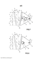
[0046] A Figura 3 mostra uma vista lateral de um mecanismo de movimento de acordo com uma segunda concretização preferível da invenção;[0046] Figure 3 shows a side view of a movement mechanism according to a second preferred embodiment of the invention;
[0047] A Figura 4 mostra uma vista lateral de um mecanismo de movimento de acordo com uma terceira concretização preferível da invenção;[0047] Figure 4 shows a side view of a movement mechanism according to a third preferred embodiment of the invention;
[0048] A Figura 5 mostra uma vista lateral de um mecanismo de movimento de acordo com uma quarta concretização preferível da invenção;[0048] Figure 5 shows a side view of a movement mechanism according to a fourth preferred embodiment of the invention;
[0049] A Figura 6 mostra um britador de mandíbulasalternativo semelhante ao britador de mandíbulas na Figura 3;[0049] Figure 6 shows an alternative jaw crusher similar to the jaw crusher in Figure 3;
[0050] A Figura 7 mostra um britador de mandíbulas alternativo semelhante aos britadores de mandíbulas nas figuras 4 e 5;[0050] Figure 7 shows an alternative jaw crusher similar to the jaw crushers in figures 4 and 5;
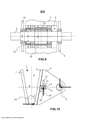
[0051] A Figura 8 mostra uma vista lateral de um mecanismo de movimento de acordo com uma quinta concretização preferível da invenção;[0051] Figure 8 shows a side view of a movement mechanism according to a fifth preferred embodiment of the invention;
[0052] A Figura 9 mostra uma seção transversal de um arranjo de excêntrico preferível do mecanismo de movimento mostrado na Figura 8; e[0052] Figure 9 shows a cross section of a preferable cam arrangement of the movement mechanism shown in Figure 8; and
[0053] A Figura 10 mostra um exemplo de um dispositivo de segurança, de acordo com uma primeira concretização preferível da invenção, apresentado com o mecanismo de movimento da Figura 2.[0053] Figure 10 shows an example of a safety device, according to a first preferred embodiment of the invention, presented with the movement mechanism of Figure 2.
[0054] Na descrição a seguir, números semelhantes indicam elementos similares. Deve ser apreciado que os desenhos ilustrados não estão inteiramente em escala, e que os desenhos servem principalmente o propósito de ilustrar alguns exemplos de concretizações da invenção.[0054] In the following description, similar numbers indicate similar elements. It should be appreciated that the illustrated drawings are not entirely to scale, and that the drawings primarily serve the purpose of illustrating some examples of embodiments of the invention.
[0055] A Figura 1 mostra um equipamento de processamento de material mineral, uma unidade de britagem 200 que compreende um britador de mandíbula 100. A unidade de britagem 200 tem um alimentador 103 para a alimentação do material ao britador de mandíbulas 100, e um transportador de correia 106 para transportar o material triturado mais afastada da unidade de britagem.[0055] Figure 1 shows mineral material processing equipment, a crushing
[0056] A correia transportadora 106, mostrada na Figura 1, compreende uma correia 107 a qual é adaptada para passar em torno de pelo menos um rolo 108. A unidade de britagem 200 compreende também uma fonte de alimentação e uma unidade de controle 105. A fonte de alimentação pode ser, por exemplo, um motor diesel ou um motor elétrico que está fornecendo energia para as unidades de processamento e circuitos hidráulicos.[0056] The
[0057] O alimentador 103, o britador 100, a fonte de alimentação 105 e o transportador 106 estão anexados a um corpo 101 da unidade de britagem, corpo que, nesta concretização, adicionalmente compreende uma base em largarta 102 para mover a unidade de britagem 200. A unidade de britagem pode também ser de forma total ou parcial baseada em rodas, ou móvel sobre as pernas. Alternativamente, pode ser móvel/rebocável, por exemplo, por um caminhão ou outra fonte de alimentação externa. Alternativamente, a unidade de britagem pode ser uma unidade fixa.[0057] The
[0058] O material mineral pode ser, por exemplo, rocha extraída ou pode ser resíduos de asfalto ou de demolição de construção, tais como, concreto ou tijolos, etc.. Adicionalmente, ao acima a unidade de britagem pode também ser uma unidade fixa.[0058] The mineral material can be, for example, extracted rock or it can be asphalt or construction demolition waste, such as concrete or bricks, etc. In addition to the above the crushing unit can also be a fixed unit .
[0059] As concretizações dos mecanismos de movimento de um britador de mandíbula 100 mostrados nas Figuras 2 a 10, podem ser utilizadas, por exemplo, na unidade de britagem 200 da Figura 1.[0059] Embodiments of the movement mechanisms of a
[0060] O britador de mandíbulas 100 mostrado nas Figuras 1 a 10, compreende uma mandíbula fixa e mandíbula móvel para a formação de uma câmara de britagem 3 entre as mesmas, que é aberta na porção superior. Uma primeira peça de desgaste 1 é anexada à mandíbula fixa e uma segunda peça de desgaste 2 é fixada a um queixo 4. Nas Figuras 2 a 10, a mandíbula fixa é representada por a peça de desgaste 1 anexada à mandíbula fixa, e a mandíbula móvel é representada pela peça de desgaste 2 anexada a um queixo 4. A câmara de britagem 3 compreende uma seção superior 5, uma seção mediana 6 e uma seção inferior 7 tendo alturas h iguais. O mecanismo de movimento do britador de mandíbulas é baseado em um anexo do queixo 4, em primeiro lugar a um eixo excêntrico rotativo 8, e em segundo lugar para pelo menos um elemento deslizante 9 configurado para deslizar em uma direção substancialmente perpendicular em relação à diagonal vertical 10 da câmara de britagem 3. Preferivelmente, uma linha substancialmente horizontal 11, passando através do centro do eixo excêntrico 8, passa através da seção mediana 6 da câmara de britagem 3.[0060] The
[0061] Preferivelmente, a linha substancialmente horizontal 11, passando através do centro do eixo excêntrico 8, passa substancialmente através da linha de centro horizontal 3' da câmara de britagem 3, dividindo assim, a câmara de britagem em duas partes de igual altura H.[0061] Preferably, the substantially
[0062] O eixo excêntrico 8 é rotativamente montado mancalizado por um lado em um primeiro ponto de apoio ao queixo 4, e por outro lado a um corpo (não mostrado nas Figuras) do britador de mandíbulas. A excentricidade do eixo excêntrico é utilizada para criar o curso do queixo 4 e, assim, da mandíbula móvel. Preferivelmente, a excentricidade do eixo excêntrico 8 é igual a metade do comprimento do curso da mandíbula móvel.[0062] The
[0063] O queixo 4 é adicionalmente apoiado ao corpo 2 pelo menos em um segundo ponto de apoio por pelo menos um elemento deslizante 9. Preferivelmente, pelo menos um elemento deslizante 9 é configurado para deslizar (em relação ao corpo do britador) entre uma superfície de deslizamento inferior 12 e uma superfície de deslizamento superior 13, que estão direcionadas voltadas o elemento deslizante 9. A superfície de deslizamento superior elimina um movimento direcionado para cima do elemento deslizante 9, e a superfície de deslizamento inferior elimina um movimento direcionado para baixo do elemento deslizante 9 mantendo assim um percurso de movimento linear do queixo na região de fixação do elemento deslizante.[0063] The
[0064] O elemento deslizante 9 é configurado para receber tanto a compressão e a tensão em diferentes situações de carga, em outras palavras, para receber as forças direcionadas tanto para cima e para baixo, dependendo da localização do material triturável em locais superiores ou locais inferiores da câmara de britagem 3 e da força resultante resultando deste ponto (ver também a Figura 10).[0064] The sliding
[0065] O elemento deslizante 9 está, preferivelmente, localizado horizontalmente o mais próximo possível da superfície de desgaste da peça de desgaste 2 do queixo 4, sendo que um movimento vertical muito curto possa ser adquirido para a mandíbula móvel na Figura 2. A diminuição do movimento vertical da superfície de desgaste do queixo em relação à mandíbula fixa reduz a energia necessária do britador quando o material a ser triturado não deve ser verticalmente friccionado entre as mandíbulas.[0065] The sliding
[0066] A proximidade da fixação do elemento deslizante 9 ao queixo 4 traz a superfície de desgaste da segunda peça de desgaste 2 mais, preferencialmente, para a diagonal vertical 10 da câmara de britagem 3, com a proximidade da superfície de desgaste pode também o eixo excêntrico 7 ser trazido e o britador pode ser encurtado. O britador pode ser um britador reduzido, e britador compacto pode ser criado quando o eixo excêntrico e, se necessário, um volante a ele conectado, possa ser trazido menor do que no britador de abanadeira individual.[0066] The proximity of the fastening of the sliding
[0067] Preferivelmente, a diagonal vertical 10 da câmara de britagem 3 tem a direção da gravidade, conforme mostrado nas Figuras 2-8 e 10. Assim, a câmara de britagem 3 pode ser construída de modo que as peças de desgaste 1, 2 da mandíbula fixa e da mandíbula móvel desgastem igualmente, por exemplo, quando as peças de desgaste opostas 1, 2 tem o ângulo de inclinação igual em direções opostas em relação à vertical. Em geral, a diagonal vertical 10 da câmara de britagem 3 tem a direção de uma linha que divide o ângulo entre as mandíbulas fixa e móvel (“nip angle”) na câmara de britagem 3, isto é, a direção de um bissetor da câmara de britagem. As figuras desta descrição são desenhadas na situação preferível quando o bissetor da câmara de britagem tem a direção da gravidade.[0067] Preferably, the vertical diagonal 10 of crushing
[0068] Na britagem do material mineral a abertura da câmara de britagem deve, na prática, ter um certo tamanho, por exemplo, para a alimentação de pedras para a câmara de britagem. Através do ajuste do ângulo da mandíbula da câmara de britagem, a britagem eficiente pode ser afetada de tal modo que o material a ser britado é mantido no lugar e não se move para cima, sobre as superfícies das peças de desgaste, as quais estão fixadas à mandíbula fixa e ao queixo. O queixo 4 pode ser movido, substancialmente, perpendicular em relação à diagonal 10 da câmara de britagem 3 quando é britado com os britadores, de acordo com concretizações preferíveis da invenção, sendo que o ângulo da mandíbula pode, em alguns casos, ser aumentado em comparação com a técnica anterior. Em seguida, o britador pode também ser reduzido se for necessário.[0068] In the crushing of mineral material the opening of the crushing chamber must, in practice, have a certain size, for example, for feeding stones into the crushing chamber. By adjusting the crushing chamber jaw angle, the efficient crushing can be affected in such a way that the material to be crushed is held in place and does not move up over the surfaces of the wear parts, which are clamped. fixed jaw and chin. The
[0069] A configuração e o ângulo da mandíbula do britador de mandíbulas podem ser ajustados, através de equipamentos de ajuste (não mostrados nas Figuras), os quais estão, preferivelmente, localizados em uma extremidade superior e uma extremidade inferior da mandíbula fixa. Preferivelmente, os dispositivos de proteção de sobrecarga estão integrados nestes equipamentos de ajuste.[0069] The configuration and angle of the jaw of the jaw crusher can be adjusted, through adjustment equipment (not shown in the Figures), which are preferably located at an upper end and a lower end of the fixed jaw. Preferably, overload protection devices are integrated in these adjustment equipments.
[0070] O mecanismo de movimento da mandíbula móvel permite um curso mais eficiente em uma direção perpendicular à diagonal 10 da câmara de britagem 3. Nas concretizações mostradas nas Figuras 2 a 8, o curso é quase constante e nas Figuras 3 a 9, adicionalmente linear na região de toda a câmara de britagem.[0070] The moving jaw movement mechanism allows a more efficient stroke in a direction perpendicular to the diagonal 10 of the crushing
[0071] A Figura 2 mostra uma vista lateral de um mecanismo de movimento de acordo com uma primeira concretização preferível. Um eixo 14 ou um elemento de fixação correspondente anexado por um lado ao elemento deslizante 9 está anexado, pelo o outro lado, ao queixo 4 ou as placas laterais do corpo do britador. De modo correspondente, os o elemento deslizante 9 se desloca em relação às placas laterais ou ao queixo. Preferivelmente, o elemento deslizante 9 se desloca em um furo 15 feito nas placas laterais ou no queixo. O furo compreende, preferivelmente, duas superfícies deslizantes opostas 12, 13 adaptadas para estarem em contato direto com o elemento deslizante 9.[0071] Figure 2 shows a side view of a movement mechanism according to a first preferred embodiment. A
[0072] O percurso do movimento 16 da mandíbula móvel 2 na câmara de britagem é elíptico na Figura 2 onde o eixo excêntrico 8 sobe e abaixa a extremidade posterior do queixo onde o eixo excêntrico está localizado. O eixo geométrico longitudinal do percurso do movimento 16 é perpendicular à diagonal 10 da câmara de britagem 3. Quando o elemento deslizante 9 é trazido tão próximo quanto possível da diagonal da câmara de britagem, o percurso de movimento 16 é plano e o movimento vertical indesejado das mandíbulas fixa e móvel uma em relação a outra é minimizado.[0072] The path of
[0073] A localização do eixo excêntrico na linha substancialmente horizontal 11, passando através da seção mediana 6 da câmara de britagem 3, cria percursos de movimento simétricos 16 da mandíbula móvel nas seções superior e inferior 5 e 7 da câmara de britagem 3.[0073] The location of the eccentric shaft on the substantially
[0074] Na Figura 2 o eixo excêntrico 8 está configurado, do modo mais eficiente, para rotacionar no sentido horário, isto é, a porção excêntrica do eixo excêntrico se move para cima ao lado da câmara de britagem 3, mostrado por uma seta abaixo do eixo excêntrico. A referida direção de rotação do eixo excêntrico 8 produz, com o mecanismo de movimento descrito, um sentido anti-horário dos percursos de movimento 16 mostrado pelas setas acima dos percursos de movimento.[0074] In Figure 2 the
[0075] A Figura 3 mostra uma vista lateral de um mecanismo de movimento de acordo com uma segunda concretização preferível. Um percurso de movimento totalmente linear 16 da mandíbula móvel é obtido com (pelo menos) dois elementos deslizantes configurados para deslizar em uma direção substancialmente perpendicular à diagonal vertical 10 da câmara de britagem. O britador de mandíbulas da Figura 3 compreende um elemento deslizante adicional para o primeiro elemento deslizante 9, mostrado na Figura 2, ou seja, um segundo elemento deslizante 9’ na extremidade posterior do queixo 4, semelhante em função ao primeiro elemento deslizante 9, descrito na Figura 2, em contato com as duas superfícies de deslizamento opostas, e um terceiro elemento deslizante adicional 19 o qual está disposto entre o eixo excêntrico 8 e o queixo 4. Preferivelmente, o terceiro elemento deslizante 19 é disposto de modo a deslizar substancialmente na vertical. O segundo elemento deslizante está disposto atrás do eixo excêntrico quando visto a partir da direção do primeiro elemento deslizante. Os primeiro e segundo elementos deslizantes 9, 9'mantêm o percurso de movimento da mandíbula móvel linear, e mantêm a mandíbula móvel na posição correta, preferivelmente, movendo na horizontal. Os primeiro 9 e segundo 9 ' elementos deslizantes são móveis em relação às placas laterais do britador ou em relação ao queixo. Os primeiro e segundo elementos deslizantes são configurados para receberem ambas a compressão e a tensão em diferentes situações de carga, em outras palavras, para receber as forças direcionadas tanto para cima e para baixo, dependendo da localização da resultante da força de britagem.[0075] Figure 3 shows a side view of a movement mechanism according to a second preferable embodiment. A fully
[0076] O terceiro elemento deslizante 19 é configurado para transferir o movimento do excêntrico para o movimento do queixo em uma direção substancialmente perpendicular à diagonal vertical 10 da câmara de britagem. Mais particularmente, o terceiro elemento deslizante 19 é configurado para transferir o movimento excêntrico do eixo excêntrico para o movimento horizontal do queixo 4 e, preferivelmente, para eliminar o componente de movimento vertical do eixo excêntrico 8. O terceiro elemento deslizante 19 desliza na lateral do queixo 4, preferivelmente, em uma abertura 17 no queixo. O queixo 4, preferivelmente, a abertura 17 compreende terceira 18 e quarta 18 ' superfícies deslizantes as quais estão direcionadas ao terceiro elemento deslizante 19 e adaptadas para estarem em contato direto com o terceiro elemento deslizante.[0076] The third sliding
[0077] Uma localização preferível de todos os elementos deslizantes 9, 9', 19 (também do eixo excêntrico 8) é sobre uma linha 11 perpendicular à diagonal 10 da câmara de britagem 3 e verticalmente na altura da linha de centro horizontal 3’ da câmara de britagem. Localizações alternativas dos primeiro e segundo elementos deslizantes são descritos em conexão com as Figuras 6 e 7.[0077] A preferable location of all the sliding
[0078] Quando a linha substancialmente horizontal 11 passa através dos pontos de apoio do queixo 4, preferivelmente, através dos primeiro e segundo elementos deslizantes, e através da seção mediana 6 da câmara de britagem 3, os primeiro e segundo elementos deslizantes recebem forças direcionadas voltadas a seção superior e inferior, e é eliminado qualquer descolamento, dos primeiro e segundo elementos deslizantes, do contato com as superfícies superior e inferior.[0078] When the substantially
[0079] A Figura 4 mostra uma vista lateral de um mecanismo de movimento de acordo com uma terceira concretização preferível da invenção. Um percurso de movimento totalmente linear 16 da mandíbula móvel é obtido com os primeiro e segundo elementos deslizantes 9, 9', como na Figura 3. O movimento de britagem da mandíbula móvel da Figura 4 é produzido pelo eixo excêntrico 8, e um mecanismo de haste de conexão compreendendo uma haste de conexão 20 conectada entre o excêntrico do eixo excêntrico e o elemento de fixação tal como um eixo 21 do segundo elemento deslizante 9'. O mecanismo de haste de conexão é configurado para transferir o movimento excêntrico do eixo excêntrico para o movimento horizontal do queixo 4 e para isolar a componente de movimento vertical do eixo excêntrico 8.[0079] Figure 4 shows a side view of a movement mechanism according to a third preferred embodiment of the invention. A fully
[0080] Os primeiro e segundo elementos deslizantes 9, 9' mantêm o percurso de movimento linear da mandíbula móvel e mantêm a mandíbula móvel na posição correta. Os primeiro 9 e segundo 9' elementos deslizantes são móveis em relação às placas laterais do britador ou em relação ao queixo. Os primeiro e segundo elementos deslizantes são configurados para receber tanto a compressão e a tensão em diferentes situações de carga, em outras palavras, para receber as forças direcionadas tanto para cima e para baixo, dependendo da localização da resultante da força de britagem.[0080] The first and second sliding
[0081] Uma localização preferida dos dois elementos deslizantes 9, 9' e do eixo excêntrico 8 é sobre uma linha 11 perpendicular à diagonal 10 da câmara de britagem 3, e verticalmente na altura da linha de centro horizontal 3’ da câmara de britagem. Localizações alternativas dos primeiro e segundo elementos deslizantes são descritas em conexão com as Figuras 6 e 7.[0081] A preferred location of the two sliding
[0082] O mecanismo de movimento na Figura 5 é basicamente como o mecanismo de movimento na Figura 4, mas a haste de conexão 20 está pivotada ao elemento de fixação 14 do primeiro elemento deslizante 9 ao contrário do elemento de fixação 21 do segundo elemento deslizante 9'. As mesmas vantagens para o movimento são alcançadas como na Figura 4. Naturalmente, a haste de conexão pode estar acoplada em ambos o primeiro e o segundo elementos deslizantes.[0082] The movement mechanism in Figure 5 is basically like the movement mechanism in Figure 4, but the connecting
[0083] As Figuras 6 e 7 mostram britadores de mandíbulas alternativos semelhantes aos britadores de mandíbulas nas figuras 3 a 5, nas quais os britadores de mandíbulas compreendem dois elementos deslizantes configurados para deslizarem em uma direção substancialmente perpendicular em relação à diagonal vertical 10 da câmara de britagem.[0083] Figures 6 and 7 show alternative jaw crushers similar to the jaw crushers in Figures 3 to 5, in which the jaw crushers comprise two sliding elements configured to slide in a substantially perpendicular direction to the vertical diagonal 10 of the chamber of crushing.
[0084] No exemplo da Figura 6, os primeiro e segundo elementos deslizantes 9, 9', da segunda concretização do britador de mandíbulas, estão localizados na mesma altura vertical, mas a um nível de altura vertical diferente do que do eixo excêntrico 8. Na Figura 6 uma alternativa adicional para uma localização de altura diferente de um elemento deslizante é representada com uma linha tracejada e indicada com um número de referência 9”. Os primeiro e segundo elementos deslizantes, podem também estarem localizados em diferentes níveis de verticais, quando eles estão configurados para deslizarem em uma direção substancialmente perpendicular à diagonal vertical da câmara de britagem. Os exemplos descritos do nível de altura de acordo com a Figura 6 podem também serem aplicados com as terceira e quarta concretizações do britador de mandíbulas.[0084] In the example of Figure 6, the first and second sliding
[0085] No exemplo da Figura 7, os primeiro e segundo elementos deslizantes 9, 9'da terceira concretização do britador de mandíbulas estão localizados em diferentes níveis verticais. No exemplo da Figura 7 um dos elementos deslizantes está localizado no mesmo nível de altura como o eixo excêntrico 8. Os exemplos descritos do nível de altura de acordo com a Figura 7 podem também serem aplicados com a segunda concretização do britador de mandíbulas.[0085] In the example of Figure 7, the first and second sliding
[0086] A quinta concretização preferível do mecanismo de movimento mostrado na Figura 8 compreende um elemento excêntrico 22 adicional, tal como, uma luva excêntrica montada em torno do excêntrico do eixo excêntrico 8 que está localizado na extremidade frontal do queixo 4 próximo da câmara de britagem ou da segunda peça de desgaste 2. O segundo elemento excêntrico 22 é configurado para girar (um dispositivo de rotação 23 na Figura 9) em uma direção de rotação oposta do que o eixo excêntrico 8, conforme é indicado com as setas direcionadas opostas na Figura 8. Preferivelmente, a excentricidade e velocidade rotacional de ambos os elementos excêntricos 8 e 22 estão dispostas de forma igual, de modo que um percurso de movimento horizontal e totalmente linear 16 da mandíbula móvel seja obtido.[0086] The fifth preferable embodiment of the movement mechanism shown in Figure 8 comprises an additional
[0087] Os dois excêntricos 8, 22 unidos entre si e o segundo elemento deslizante 9', mantêm o percurso de movimento linear da mandíbula móvel, e mantêm a mandíbula móvel na posição correta. O segundo elemento deslizante 9’ se move em relação às placas laterais do britador ou em relação ao queixo. Os dois excêntricos 8, 22 unidos entre si e o segundo elemento deslizante 9' estão configurados para receberem ambas a compressão e a tensão em diferentes situações de carga, em outras palavras, para receberem as forças direcionadas tanto para cima e para baixo, dependendo da localização da resultante das forças de britagem na câmara de britagem 3.[0087] The two
[0088] A Figura 9 mostra um corte transversal de um exemplo de arranjo excêntrico do mecanismo de movimento mostrado na Figura 8. O eixo excêntrico 8 está montado mancalizado ao corpo, tal como as placas laterais 24 do britador de mandíbulas 100. Primeiro, a luva excêntrica 22 é montada mancalizada a e em torno do excêntrico 8' do eixo excêntrico 8, e segundo no interior de um furo 4’ do queixo 4. O dispositivo de rotação 23 é acoplado com o queixo 4 e a luva excêntrica 22 tendo um exemplo de contrapeso 25.[0088] Figure 9 shows a cross-section of an example of an eccentric arrangement of the movement mechanism shown in Figure 8. The
[0089] A Figura 10 mostra um dispositivo de segurança de sobrecarga 26, 27 com o mecanismo de movimento da Figura 2. O dispositivo de segurança compreende cilindros hidráulicos inferior e superior 26, 27, com um limite da pressão de segurança específico, dispostos para suportar verticalmente o elemento deslizante 9, preferivelmente, através das superfícies deslizantes inferior e superior 12, 13. Tipicamente, uma resultante da força de britagem é causada na porção superior 5 (por exemplo, uma grande pedra) ou na seção inferior 7 (por exemplo, um pedaço de metal ou enchimento de material fino) da câmara de britagem 3, sendo que o elemento deslizante 9 (e/ou o segundo elemento deslizante 9') recebe elevadas forças verticais. No exemplo da Figura 9, o material 28 é comprimido na seção inferior 7 da câmara de britagem, sendo que o cilindro hidráulico inferior 26 suporta o elemento deslizante 9 com uma força vertical 29.[0089] Figure 10 shows an
[0090] Preferivelmente, o arranjo de cilindro hidráulico 26, 27 acima mencionado está configurado para manter as folgas apropriadas entre o elemento deslizante 9 (e/ou o segundo elemento deslizante 9') e as superfícies superior e inferior 12, 13 durante a operação normal.[0090] Preferably, the aforementioned
[0091] De acordo com outro exemplo de um dispositivo de segurança, o eixo de fixação 14, 21 de um primeiro 9 e/ou segundo 9' elemento deslizante é dimensionado para uma força de cisalhamento específica.[0091] According to another example of a safety device, the
[0092] A invenção permite a criação de um percurso de movimento 16 mais eficiente da mandíbula móvel do britador de mandíbulas 100 em termos de eficiência e desgaste das peças de desgaste. Um movimento substancialmente linear pode ser obtido, o qual é perpendicular à diagonal da câmara de britagem e tem tamanho igual em toda a câmara de britagem. Um curso suficiente é obtido na porção superior da câmara de britagem, de modo que também grandes pedras sejam britadas com uma tensão de compressão final necessária de cerca de 0,2%. O grande curso na seção inferior da câmara de britagem aumenta a capacidade do britador 100 e da unidade de britagem 200. O curso linear, que é perpendicular à diagonal da câmara de britagem desgasta minimamente as peças de desgaste.[0092] The invention allows the creation of a more
[0093] Todas as alternativas do mecanismo de movimento acima mencionadas utilizam um ou dois elementos deslizantes tendo a mesma direção de deslizamento. Os elementos deslizantes, preferivelmente, suportam forças bilateralmente. As placas que se deslocam horizontalmente suportam, preferivelmente, forças direcionadas para baixo para cima. Preferivelmente, o elemento deslizante e o eixo excêntrico estão localizados sobre a linha passando através da seção mediana da câmara de britagem.[0093] All of the aforementioned movement mechanism alternatives use one or two sliding elements having the same sliding direction. The sliding elements preferably bear forces bilaterally. The horizontally moving plates preferably withstand forces directed downwards upwards. Preferably, the sliding element and the eccentric shaft are located on the line passing through the mid-section of the crushing chamber.
[0094] A aplicação da Figura 1 é bastante simples e fácil de implementar com um relativamente bom percurso de movimento 16 em toda a região da câmara de britagem 3. Se a câmara de britagem é muito alta o curso na seção mediana 6 da câmara de britagem permanece menor do que o curso nas seções superior e inferior 5, 7. Preferivelmente, uma primeira distância entre o eixo excêntrico 8 e o primeiro elemento deslizante 9 é disposta substancialmente maior do que uma segunda distância entre a diagonal 10 da câmara de britagem e o primeiro elemento deslizante 9. Quanto maior for a referida primeira distância em relação a referida segunda distância, melhor o percurso de movimento.[0094] The application of Figure 1 is quite simple and easy to implement with a relatively
[0095] Nas alternativas das Figuras 3 a 7 o percurso de movimento da mandíbula móvel é bom, mas, por exemplo, mais um eixo 21 é necessário. Preferivelmente, um balanceamento do britador de mandíbulas é facilmente implementado, uma vez que o movimento da mandíbula móvel é linear e não existe qualquer movimento de oscilação do queixo.[0095] In the alternatives of Figures 3 to 7 the movement path of the movable jaw is good, but, for example, one
[0096] A construção de acordo com a Figura 8 é mais eficiente em termos de funcionamento. O movimento é linear, perpendicular à diagonal da câmara de britagem, e o curso é igual em todas as seções da câmara de britagem 3. Adicionalmente, os dois elementos excêntricos concêntricos 8, 22 rotacionando em direções opostas para permitir o balanceamento completo do britador 100. O balanceamento de um britador tendo uma largura de mandíbula de 800 mm e dois volantes pode ser implementado através da montagem de um peso de cerca de 10 kg para cada volante, e um contrabalanço 25 de 75 kg para a luva excêntrica 22. Isto ainda permite fixar rigidamente a mandíbula fixa ao britagem móvel 200, e preferivelmente, utilizar as placas laterais como partes de suporte de carga da unidade de britagem móvel.[0096] The construction according to Figure 8 is more efficient in terms of operation. The movement is linear, perpendicular to the diagonal of the crushing chamber, and the stroke is equal in all sections of the crushing
[0097] Em função do aumento da capacidade o britador com o mecanismo de movimento descrito pode, preferivelmente, ser operado como um segundo britador de estágio. De acordo com um exemplo, a extensão da abertura da câmara de britagem na direção longitudinal da unidade de britagem é de 300 mm e o ajuste é de 40 mm. Com um ângulo de distanciamento de 24° a câmara de britagem 3 tem apenas cerca de 600 mm de altura. Nas montagens móveis isto proporciona vantagens com mandíbulas largas.[0097] Due to the increase in capacity the crusher with the described movement mechanism can preferably be operated as a second stage crusher. According to an example, the extension of the crushing chamber opening in the longitudinal direction of the crushing unit is 300 mm and the setting is 40 mm. With a spacing angle of 24°, the crushing
[0098] A descrição acima proporciona exemplos não limitativos de algumas concretizações da invenção. É claro para um técnico no assunto que a invenção não está restrita aos detalhes apresentados, mas que a invenção pode ser implementada de outros meios equivalentes.[0098] The above description provides non-limiting examples of some embodiments of the invention. It is clear to a person skilled in the art that the invention is not restricted to the details presented, but that the invention can be implemented by other equivalent means.
[0099] Algumas das características das concretizações acima descritas podem ser utilizadas com vantagem sem a utilização de outras características. Tal como, a descrição acima deve ser considerada como meramente ilustrativa dos princípios da invenção, e não limitação da mesma. Assim, o escopo da presente invenção é apenas limitado pelas reivindicações da patente anexas.[0099] Some of the features of the embodiments described above can be used to advantage without the use of other features. As such, the above description is to be considered merely illustrative of the principles of the invention, and not limitation thereof. Thus, the scope of the present invention is only limited by the appended patent claims.
Claims (20)
Applications Claiming Priority (1)
| Application Number | Priority Date | Filing Date | Title |
|---|---|---|---|
| PCT/FI2013/051074 WO2015071525A1 (en) | 2013-11-14 | 2013-11-14 | Jaw crusher, crushing plant and crushing method |
Publications (2)
| Publication Number | Publication Date |
|---|---|
| BR112016010882A2 BR112016010882A2 (en) | 2017-08-08 |
| BR112016010882B1 true BR112016010882B1 (en) | 2021-08-31 |
Family
ID=49726809
Family Applications (1)
| Application Number | Title | Priority Date | Filing Date |
|---|---|---|---|
| BR112016010882-5A BR112016010882B1 (en) | 2013-11-14 | 2013-11-14 | JAW CRUSHER, CRUSHING UNIT AND METHOD FOR CRUSHING MINERAL MATERIAL IN A JAW CRUSHER OR IN A CRUSHING UNIT |
Country Status (8)
| Country | Link |
|---|---|
| US (1) | US10543487B2 (en) |
| EP (1) | EP3068537B1 (en) |
| JP (1) | JP6343668B2 (en) |
| CN (1) | CN105813757B (en) |
| AU (1) | AU2013405447B2 (en) |
| BR (1) | BR112016010882B1 (en) |
| WO (1) | WO2015071525A1 (en) |
| ZA (1) | ZA201603166B (en) |
Families Citing this family (6)
| Publication number | Priority date | Publication date | Assignee | Title |
|---|---|---|---|---|
| FI126205B (en) | 2015-05-13 | 2016-08-15 | Metso Minerals Inc | Jaw crusher, plant for processing mineral materials and process for processing mineral materials |
| USD872141S1 (en) | 2018-08-10 | 2020-01-07 | Superior Industries, Inc. | Jaw crusher forward wall |
| CN110420991B (en) * | 2019-08-14 | 2021-09-03 | 鼎信阳光环境技术有限公司 | Cadmium-polluted soil remediation method |
| CN111215166A (en) * | 2020-01-21 | 2020-06-02 | 山东华锴重工机械有限公司 | Roller jaw crusher |
| CN114247503A (en) * | 2021-12-21 | 2022-03-29 | 无锡市鑫燕粉体机械有限公司 | Circulating high-efficient double-roll crusher |
| CN114618616B (en) * | 2022-03-15 | 2023-04-07 | 上海山裕机械有限公司 | Jaw crusher |
Family Cites Families (13)
| Publication number | Priority date | Publication date | Assignee | Title |
|---|---|---|---|---|
| GB275100A (en) | 1927-02-16 | 1927-08-04 | August Mueller | Improvements in stone crushers |
| US2173862A (en) * | 1938-03-01 | 1939-09-26 | Ernest D Rowe | Jaw crusher mechanism |
| US2257388A (en) * | 1940-08-02 | 1941-09-30 | George E Krider | Triple crushing machine |
| CH217566A (en) * | 1942-03-10 | 1941-10-31 | Robert Aebi & Cie A G | Charcoal Crusher. |
| DE2606858C2 (en) * | 1976-02-20 | 1981-12-10 | Alfred 4200 Oberhausen Schmitz | Jaw crusher and processing plant |
| JPS63141639U (en) * | 1987-03-07 | 1988-09-19 | ||
| JP3359650B2 (en) * | 1991-12-03 | 2002-12-24 | メッツォ・ミネラルズ・ジャパン株式会社 | Mobile crusher |
| JPH07313891A (en) * | 1994-05-23 | 1995-12-05 | Kotobuki Giken Kogyo Kk | Mechanism for adjusting blade plate stroke of jaw crusher |
| CN2224023Y (en) * | 1995-09-19 | 1996-04-10 | 北京矿冶研究总院 | Low-frame fine jaw crusher |
| JP3052632U (en) * | 1998-03-25 | 1998-09-29 | 株式会社山産 | Jaw crusher |
| CN2332475Y (en) * | 1998-08-14 | 1999-08-11 | 北京矿冶研究总院 | Cascade cavity large-crushing-ratio jaw crusher |
| FI109662B (en) * | 2001-08-31 | 2002-09-30 | Metso Minerals Tampere Oy | Transport locking arrangement for vibrating feeder of mobile crushing unit characterized in that downward rotatable sidewall of feeder hopper in its lower position is capable of locking vibrating feeder rigidly to framework of crushing unit |
| WO2012139483A1 (en) * | 2011-04-13 | 2012-10-18 | 义乌黑白矿山机械有限公司 | Jaw crusher with double crank-rocker mechanisms |
-
2013
- 2013-11-14 AU AU2013405447A patent/AU2013405447B2/en active Active
- 2013-11-14 US US15/036,146 patent/US10543487B2/en active Active
- 2013-11-14 BR BR112016010882-5A patent/BR112016010882B1/en active IP Right Grant
- 2013-11-14 JP JP2016530001A patent/JP6343668B2/en active Active
- 2013-11-14 CN CN201380080964.5A patent/CN105813757B/en active Active
- 2013-11-14 EP EP13802417.9A patent/EP3068537B1/en active Active
- 2013-11-14 WO PCT/FI2013/051074 patent/WO2015071525A1/en active Application Filing
-
2016
- 2016-05-11 ZA ZA2016/03166A patent/ZA201603166B/en unknown
Also Published As
| Publication number | Publication date |
|---|---|
| CN105813757B (en) | 2018-10-16 |
| BR112016010882A2 (en) | 2017-08-08 |
| CN105813757A (en) | 2016-07-27 |
| EP3068537B1 (en) | 2018-07-18 |
| EP3068537A1 (en) | 2016-09-21 |
| ZA201603166B (en) | 2018-12-19 |
| AU2013405447B2 (en) | 2018-04-26 |
| AU2013405447A1 (en) | 2016-06-23 |
| JP2016540631A (en) | 2016-12-28 |
| JP6343668B2 (en) | 2018-06-13 |
| US20160288127A1 (en) | 2016-10-06 |
| US10543487B2 (en) | 2020-01-28 |
| WO2015071525A1 (en) | 2015-05-21 |
Similar Documents
| Publication | Publication Date | Title |
|---|---|---|
| BR112016010882B1 (en) | JAW CRUSHER, CRUSHING UNIT AND METHOD FOR CRUSHING MINERAL MATERIAL IN A JAW CRUSHER OR IN A CRUSHING UNIT | |
| BR112015009402B1 (en) | Eccentric Roll Crusher | |
| BR112017023727B1 (en) | HIGH COMPRESSION ROLLER MILL | |
| BR112015009411B1 (en) | ROLL CRUSHER | |
| US9873123B2 (en) | Jaw crusher, a crushing plant, and a method for using a jaw crusher | |
| CN107700925A (en) | A kind of fixed structure of pile and column | |
| CN203794124U (en) | Conveying device | |
| AU2013242180A1 (en) | Jaw crusher | |
| RU179485U1 (en) | TWO-CHAMBER JAW CRUSHER | |
| RU2013118516A (en) | JAW CRUSHERS WITH HIGH CRUSHING GRINDING ACTION | |
| JP2008284519A (en) | Set adjusting device for impact crusher | |
| CN208302907U (en) | A kind of lower counterpunch board assembling structure of composite crusher | |
| BR112017023642B1 (en) | JAW CRUSHER, MINERAL MATERIAL PROCESSING UNIT AND METHOD FOR PROCESSING MINERAL MATERIAL IN A JAW CRUSHER | |
| JP6494735B1 (en) | Crusher equipment | |
| CN209715205U (en) | A kind of gyratory crusher | |
| CN218422965U (en) | Novel jaw crusher with adjustable jaw plates | |
| CN207929380U (en) | A kind of silicon original stone breaker | |
| CN104727682B (en) | A kind of base tunable arrangement of floor spring | |
| CN103706426A (en) | Discharge port adjusting device of jaw crusher | |
| CN204184974U (en) | Five coating device and unreeling structure thereof | |
| ES2796826T3 (en) | Scraping device of a conveyor belt | |
| BR112016020030B1 (en) | JAW CRUSHER, CRUSHING INSTALLATION AND METHOD FOR USING A JAW CRUSHER | |
| CN106743543A (en) | Assembly line material disc wing drop clamping device |
Legal Events
| Date | Code | Title | Description |
|---|---|---|---|
| B08F | Application dismissed because of non-payment of annual fees [chapter 8.6 patent gazette] | ||
| B08G | Application fees: restoration [chapter 8.7 patent gazette] | ||
| B06U | Preliminary requirement: requests with searches performed by other patent offices: procedure suspended [chapter 6.21 patent gazette] | ||
| B09A | Decision: intention to grant [chapter 9.1 patent gazette] | ||
| B25D | Requested change of name of applicant approved |
Owner name: METSO OUTOTEC FINLAND OY (FI) |
|
| B25G | Requested change of headquarter approved |
Owner name: METSO OUTOTEC FINLAND OY (FI) |
|
| B16A | Patent or certificate of addition of invention granted [chapter 16.1 patent gazette] |
Free format text: PRAZO DE VALIDADE: 20 (VINTE) ANOS CONTADOS A PARTIR DE 14/11/2013, OBSERVADAS AS CONDICOES LEGAIS. |
|
| B25K | Entry of change of name and/or headquarter and transfer of application, patent and certificate of addition of invention: republication |
Owner name: METSO OUTOTEC FINLAND OY (FI) Free format text: RETIFICACAO DO DESPACHO (25.7) ? ALTERACAO DE SEDE PUBLICADO NA RPI NO 2640, DE 10/08/2021, QUANTO AO ITEM (71) ? DEPOSITANTE NO PARECER.ONDE SE LE: METSO MINERALS, INC.LEIA-SE: METSO OUTOTEC FINLAND OY |