BR112013028750B1 - BRAKE AND METHOD FOR MAKING A BRAKE - Google Patents
BRAKE AND METHOD FOR MAKING A BRAKE Download PDFInfo
- Publication number
- BR112013028750B1 BR112013028750B1 BR112013028750-0A BR112013028750A BR112013028750B1 BR 112013028750 B1 BR112013028750 B1 BR 112013028750B1 BR 112013028750 A BR112013028750 A BR 112013028750A BR 112013028750 B1 BR112013028750 B1 BR 112013028750B1
- Authority
- BR
- Brazil
- Prior art keywords
- brake
- damper plate
- armature
- armature part
- plate
- Prior art date
Links
- 238000000034 method Methods 0.000 title claims abstract description 5
- 238000013016 damping Methods 0.000 claims abstract description 33
- 238000005452 bending Methods 0.000 claims abstract description 14
- 230000003213 activating effect Effects 0.000 claims abstract 2
- 229910000639 Spring steel Inorganic materials 0.000 claims description 3
- 238000003825 pressing Methods 0.000 description 6
- 239000000463 material Substances 0.000 description 5
- 230000007423 decrease Effects 0.000 description 4
- 239000002184 metal Substances 0.000 description 3
- 229910052751 metal Inorganic materials 0.000 description 3
- XEEYBQQBJWHFJM-UHFFFAOYSA-N Iron Chemical compound [Fe] XEEYBQQBJWHFJM-UHFFFAOYSA-N 0.000 description 2
- 238000013459 approach Methods 0.000 description 2
- 238000004519 manufacturing process Methods 0.000 description 2
- 229920002635 polyurethane Polymers 0.000 description 2
- 239000004814 polyurethane Substances 0.000 description 2
- 230000000284 resting effect Effects 0.000 description 2
- RYGMFSIKBFXOCR-UHFFFAOYSA-N Copper Chemical compound [Cu] RYGMFSIKBFXOCR-UHFFFAOYSA-N 0.000 description 1
- 229910000831 Steel Inorganic materials 0.000 description 1
- 239000006096 absorbing agent Substances 0.000 description 1
- 230000004913 activation Effects 0.000 description 1
- 229910052802 copper Inorganic materials 0.000 description 1
- 239000010949 copper Substances 0.000 description 1
- 230000006866 deterioration Effects 0.000 description 1
- 238000009826 distribution Methods 0.000 description 1
- 239000013013 elastic material Substances 0.000 description 1
- 229920001971 elastomer Polymers 0.000 description 1
- ZZUFCTLCJUWOSV-UHFFFAOYSA-N furosemide Chemical compound C1=C(Cl)C(S(=O)(=O)N)=CC(C(O)=O)=C1NCC1=CC=CO1 ZZUFCTLCJUWOSV-UHFFFAOYSA-N 0.000 description 1
- 229910052742 iron Inorganic materials 0.000 description 1
- 238000000465 moulding Methods 0.000 description 1
- 230000035939 shock Effects 0.000 description 1
- 239000010959 steel Substances 0.000 description 1
Images


Classifications
-
- F—MECHANICAL ENGINEERING; LIGHTING; HEATING; WEAPONS; BLASTING
- F16—ENGINEERING ELEMENTS AND UNITS; GENERAL MEASURES FOR PRODUCING AND MAINTAINING EFFECTIVE FUNCTIONING OF MACHINES OR INSTALLATIONS; THERMAL INSULATION IN GENERAL
- F16D—COUPLINGS FOR TRANSMITTING ROTATION; CLUTCHES; BRAKES
- F16D55/00—Brakes with substantially-radial braking surfaces pressed together in axial direction, e.g. disc brakes
- F16D55/02—Brakes with substantially-radial braking surfaces pressed together in axial direction, e.g. disc brakes with axially-movable discs or pads pressed against axially-located rotating members
- F16D55/04—Brakes with substantially-radial braking surfaces pressed together in axial direction, e.g. disc brakes with axially-movable discs or pads pressed against axially-located rotating members by moving discs or pads away from one another against radial walls of drums or cylinders
- F16D55/06—Brakes with substantially-radial braking surfaces pressed together in axial direction, e.g. disc brakes with axially-movable discs or pads pressed against axially-located rotating members by moving discs or pads away from one another against radial walls of drums or cylinders without self-tightening action
- F16D55/08—Mechanically-actuated brakes
-
- F—MECHANICAL ENGINEERING; LIGHTING; HEATING; WEAPONS; BLASTING
- F16—ENGINEERING ELEMENTS AND UNITS; GENERAL MEASURES FOR PRODUCING AND MAINTAINING EFFECTIVE FUNCTIONING OF MACHINES OR INSTALLATIONS; THERMAL INSULATION IN GENERAL
- F16D—COUPLINGS FOR TRANSMITTING ROTATION; CLUTCHES; BRAKES
- F16D55/00—Brakes with substantially-radial braking surfaces pressed together in axial direction, e.g. disc brakes
- F16D55/02—Brakes with substantially-radial braking surfaces pressed together in axial direction, e.g. disc brakes with axially-movable discs or pads pressed against axially-located rotating members
- F16D55/04—Brakes with substantially-radial braking surfaces pressed together in axial direction, e.g. disc brakes with axially-movable discs or pads pressed against axially-located rotating members by moving discs or pads away from one another against radial walls of drums or cylinders
- F16D55/06—Brakes with substantially-radial braking surfaces pressed together in axial direction, e.g. disc brakes with axially-movable discs or pads pressed against axially-located rotating members by moving discs or pads away from one another against radial walls of drums or cylinders without self-tightening action
-
- B—PERFORMING OPERATIONS; TRANSPORTING
- B66—HOISTING; LIFTING; HAULING
- B66B—ELEVATORS; ESCALATORS OR MOVING WALKWAYS
- B66B1/00—Control systems of elevators in general
- B66B1/24—Control systems with regulation, i.e. with retroactive action, for influencing travelling speed, acceleration, or deceleration
- B66B1/28—Control systems with regulation, i.e. with retroactive action, for influencing travelling speed, acceleration, or deceleration electrical
- B66B1/32—Control systems with regulation, i.e. with retroactive action, for influencing travelling speed, acceleration, or deceleration electrical effective on braking devices, e.g. acting on electrically controlled brakes
-
- B—PERFORMING OPERATIONS; TRANSPORTING
- B66—HOISTING; LIFTING; HAULING
- B66B—ELEVATORS; ESCALATORS OR MOVING WALKWAYS
- B66B5/00—Applications of checking, fault-correcting, or safety devices in elevators
- B66B5/02—Applications of checking, fault-correcting, or safety devices in elevators responsive to abnormal operating conditions
- B66B5/16—Braking or catch devices operating between cars, cages, or skips and fixed guide elements or surfaces in hoistway or well
-
- F—MECHANICAL ENGINEERING; LIGHTING; HEATING; WEAPONS; BLASTING
- F16—ENGINEERING ELEMENTS AND UNITS; GENERAL MEASURES FOR PRODUCING AND MAINTAINING EFFECTIVE FUNCTIONING OF MACHINES OR INSTALLATIONS; THERMAL INSULATION IN GENERAL
- F16D—COUPLINGS FOR TRANSMITTING ROTATION; CLUTCHES; BRAKES
- F16D13/00—Friction clutches
- F16D13/22—Friction clutches with axially-movable clutching members
-
- F—MECHANICAL ENGINEERING; LIGHTING; HEATING; WEAPONS; BLASTING
- F16—ENGINEERING ELEMENTS AND UNITS; GENERAL MEASURES FOR PRODUCING AND MAINTAINING EFFECTIVE FUNCTIONING OF MACHINES OR INSTALLATIONS; THERMAL INSULATION IN GENERAL
- F16D—COUPLINGS FOR TRANSMITTING ROTATION; CLUTCHES; BRAKES
- F16D13/00—Friction clutches
- F16D13/76—Friction clutches specially adapted to incorporate with other transmission parts, i.e. at least one of the clutch parts also having another function, e.g. being the disc of a pulley
-
- F—MECHANICAL ENGINEERING; LIGHTING; HEATING; WEAPONS; BLASTING
- F16—ENGINEERING ELEMENTS AND UNITS; GENERAL MEASURES FOR PRODUCING AND MAINTAINING EFFECTIVE FUNCTIONING OF MACHINES OR INSTALLATIONS; THERMAL INSULATION IN GENERAL
- F16D—COUPLINGS FOR TRANSMITTING ROTATION; CLUTCHES; BRAKES
- F16D59/00—Self-acting brakes, e.g. coming into operation at a predetermined speed
- F16D59/02—Self-acting brakes, e.g. coming into operation at a predetermined speed spring-loaded and adapted to be released by mechanical, fluid, or electromagnetic means
-
- F—MECHANICAL ENGINEERING; LIGHTING; HEATING; WEAPONS; BLASTING
- F16—ENGINEERING ELEMENTS AND UNITS; GENERAL MEASURES FOR PRODUCING AND MAINTAINING EFFECTIVE FUNCTIONING OF MACHINES OR INSTALLATIONS; THERMAL INSULATION IN GENERAL
- F16D—COUPLINGS FOR TRANSMITTING ROTATION; CLUTCHES; BRAKES
- F16D65/00—Parts or details
- F16D65/0006—Noise or vibration control
-
- H—ELECTRICITY
- H02—GENERATION; CONVERSION OR DISTRIBUTION OF ELECTRIC POWER
- H02K—DYNAMO-ELECTRIC MACHINES
- H02K7/00—Arrangements for handling mechanical energy structurally associated with dynamo-electric machines, e.g. structural association with mechanical driving motors or auxiliary dynamo-electric machines
- H02K7/10—Structural association with clutches, brakes, gears, pulleys or mechanical starters
- H02K7/102—Structural association with clutches, brakes, gears, pulleys or mechanical starters with friction brakes
-
- F—MECHANICAL ENGINEERING; LIGHTING; HEATING; WEAPONS; BLASTING
- F16—ENGINEERING ELEMENTS AND UNITS; GENERAL MEASURES FOR PRODUCING AND MAINTAINING EFFECTIVE FUNCTIONING OF MACHINES OR INSTALLATIONS; THERMAL INSULATION IN GENERAL
- F16D—COUPLINGS FOR TRANSMITTING ROTATION; CLUTCHES; BRAKES
- F16D2121/00—Type of actuator operation force
- F16D2121/18—Electric or magnetic
- F16D2121/20—Electric or magnetic using electromagnets
- F16D2121/22—Electric or magnetic using electromagnets for releasing a normally applied brake
-
- F—MECHANICAL ENGINEERING; LIGHTING; HEATING; WEAPONS; BLASTING
- F16—ENGINEERING ELEMENTS AND UNITS; GENERAL MEASURES FOR PRODUCING AND MAINTAINING EFFECTIVE FUNCTIONING OF MACHINES OR INSTALLATIONS; THERMAL INSULATION IN GENERAL
- F16D—COUPLINGS FOR TRANSMITTING ROTATION; CLUTCHES; BRAKES
- F16D55/00—Brakes with substantially-radial braking surfaces pressed together in axial direction, e.g. disc brakes
- F16D55/24—Brakes with substantially-radial braking surfaces pressed together in axial direction, e.g. disc brakes with a plurality of axially-movable discs, lamellae, or pads, pressed from one side towards an axially-located member
- F16D55/26—Brakes with substantially-radial braking surfaces pressed together in axial direction, e.g. disc brakes with a plurality of axially-movable discs, lamellae, or pads, pressed from one side towards an axially-located member without self-tightening action
- F16D55/28—Brakes with only one rotating disc
-
- F—MECHANICAL ENGINEERING; LIGHTING; HEATING; WEAPONS; BLASTING
- F16—ENGINEERING ELEMENTS AND UNITS; GENERAL MEASURES FOR PRODUCING AND MAINTAINING EFFECTIVE FUNCTIONING OF MACHINES OR INSTALLATIONS; THERMAL INSULATION IN GENERAL
- F16D—COUPLINGS FOR TRANSMITTING ROTATION; CLUTCHES; BRAKES
- F16D65/00—Parts or details
- F16D65/02—Braking members; Mounting thereof
- F16D65/04—Bands, shoes or pads; Pivots or supporting members therefor
- F16D65/092—Bands, shoes or pads; Pivots or supporting members therefor for axially-engaging brakes, e.g. disc brakes
- F16D65/095—Pivots or supporting members therefor
- F16D65/097—Resilient means interposed between pads and supporting members or other brake parts
- F16D65/0971—Resilient means interposed between pads and supporting members or other brake parts transmitting brake actuation force, e.g. elements interposed between brake piston and pad
-
- F—MECHANICAL ENGINEERING; LIGHTING; HEATING; WEAPONS; BLASTING
- F16—ENGINEERING ELEMENTS AND UNITS; GENERAL MEASURES FOR PRODUCING AND MAINTAINING EFFECTIVE FUNCTIONING OF MACHINES OR INSTALLATIONS; THERMAL INSULATION IN GENERAL
- F16D—COUPLINGS FOR TRANSMITTING ROTATION; CLUTCHES; BRAKES
- F16D65/00—Parts or details
- F16D65/02—Braking members; Mounting thereof
- F16D65/04—Bands, shoes or pads; Pivots or supporting members therefor
- F16D65/092—Bands, shoes or pads; Pivots or supporting members therefor for axially-engaging brakes, e.g. disc brakes
- F16D65/095—Pivots or supporting members therefor
- F16D65/097—Resilient means interposed between pads and supporting members or other brake parts
- F16D65/0973—Resilient means interposed between pads and supporting members or other brake parts not subjected to brake forces
- F16D65/0974—Resilient means interposed between pads and supporting members or other brake parts not subjected to brake forces acting on or in the vicinity of the pad rim in a direction substantially transverse to the brake disc axis
- F16D65/0977—Springs made from sheet metal
-
- F—MECHANICAL ENGINEERING; LIGHTING; HEATING; WEAPONS; BLASTING
- F16—ENGINEERING ELEMENTS AND UNITS; GENERAL MEASURES FOR PRODUCING AND MAINTAINING EFFECTIVE FUNCTIONING OF MACHINES OR INSTALLATIONS; THERMAL INSULATION IN GENERAL
- F16D—COUPLINGS FOR TRANSMITTING ROTATION; CLUTCHES; BRAKES
- F16D65/00—Parts or details
- F16D65/14—Actuating mechanisms for brakes; Means for initiating operation at a predetermined position
- F16D65/28—Actuating mechanisms for brakes; Means for initiating operation at a predetermined position arranged apart from the brake
-
- Y—GENERAL TAGGING OF NEW TECHNOLOGICAL DEVELOPMENTS; GENERAL TAGGING OF CROSS-SECTIONAL TECHNOLOGIES SPANNING OVER SEVERAL SECTIONS OF THE IPC; TECHNICAL SUBJECTS COVERED BY FORMER USPC CROSS-REFERENCE ART COLLECTIONS [XRACs] AND DIGESTS
- Y10—TECHNICAL SUBJECTS COVERED BY FORMER USPC
- Y10T—TECHNICAL SUBJECTS COVERED BY FORMER US CLASSIFICATION
- Y10T29/00—Metal working
- Y10T29/49—Method of mechanical manufacture
- Y10T29/49826—Assembling or joining
Landscapes
- Engineering & Computer Science (AREA)
- General Engineering & Computer Science (AREA)
- Mechanical Engineering (AREA)
- Automation & Control Theory (AREA)
- Physics & Mathematics (AREA)
- Electromagnetism (AREA)
- Power Engineering (AREA)
- Braking Arrangements (AREA)
- Cage And Drive Apparatuses For Elevators (AREA)
Abstract
freio e método para fazer um freio. a invenção refere-se a um freio eletromagnético e um método para fazer um freio eletromagnético. o freio eletromagnético compreende uma parte da armação (1), uma parte de armadura (2) montada de maneira móvel na parte da armação e tendo um núcleo magnético (3), um ou mais elementos de mola (4) para ativar o freio a mover a dita parte de armadura (2) para frente, um eletroímã (5) encaixado na parte da armação (1) e disposto para liberar o freio ao puxar a dita parte de armadura (2) para trás pela resistência dos ditos um ou mais elementos de mola (4), e uma placa amortecedora elasticamente curvável plana (7) encaixada para ser curvada quando a parte de armadura (2) está se movendo e, enquanto é curvada, para produzir uma força de amortecimento (fd) que resiste ao curvamento para amortecer o ruído do freio.brake and method for making a brake. the invention relates to an electromagnetic brake and a method for making an electromagnetic brake. the electromagnetic brake comprises a frame part (1), an armature part (2) movably mounted on the frame part and having a magnetic core (3), one or more spring elements (4) for activating the brake to moving said armature part (2) forward, an electromagnet (5) fitted to the frame part (1) and arranged to release the brake by pulling said armature part (2) backwards by the resistance of said one or more spring elements (4), and a flat elastically bendable damping plate (7) fitted to be bent when the armature part (2) is moving and, while being bent, to produce a damping force (fd) that resists the bending to dampen brake noise.
Description
[001] A presente invenção refere-se às soluções para amortecer o ruído do freio.[001] The present invention relates to solutions to dampen brake noise.
[002] Por exemplo, em máquinas de içamento de elevador, o dispositivo de frenagem geralmente usado é um freio de máquina que engata mecanicamente a parte giratória da máquina de içamento. O freio de máquina pode ser construído, por exemplo, como um freio a tambor ou um freio a disco. O freio de máquina é ativado ao interromper o fornecimento de corrente elétrica para o eletroímã do freio. O freio de máquina usualmente tem molas que, quando o freio é ativado, força uma parte de armadura fornecida com uma pastilha de freio contra a superfície de frenagem da parte giratória para frear o movimento da parte giratória da máquina de içamento.[002] For example, in elevator lifting machines, the commonly used braking device is a machine brake that mechanically engages the rotating part of the lifting machine. The machine brake can be constructed, for example, as a drum brake or a disc brake. The machine brake is activated by interrupting the supply of electrical current to the brake electromagnet. The machine brake usually has springs which, when the brake is activated, forces an armature part provided with a brake pad against the braking surface of the rotating part to brake the movement of the rotating part of the lifting machine.
[003] O freio é liberado ao fornecer corrente para o eletroímã do freio. A liberação do freio é executada à medida que o eletroímã empurra a pastilha de freio para fora da superfície de frenagem da parte giratória da máquina de içamento ao resistir à força de pressionar produzida pelas molas. Durante a operação do elevador, o eletroímã permanece conectado ao suprimento de energia, então o freio está no estado liberado e o carro do elevador pode se mover para cima e para baixo no poço do elevador. O freio de elevador pode ser, por exemplo, implementado para que a mesma máquina de içamento compreenda dois ou mais freios de máquina.[003] The brake is released by supplying current to the brake electromagnet. Brake release is performed as the electromagnet pushes the brake pad off the braking surface of the rotating part of the lifting machine by resisting the pressing force produced by the springs. During elevator operation, the electromagnet remains connected to the power supply, so the brake is in the released state and the elevator car can move up and down in the elevator shaft. The elevator brake can, for example, be implemented so that the same lifting machine comprises two or more machine brakes.
[004] Quando a corrente através do eletroímã está caindo, a força aplicada pela mola finalmente excede a força de atração do eletroímã, e o freio é ativado. Como resultado do desequilíbrio entre as forças, a pastilha de freio atinge a superfície de frenagem da parte giratória da máquina. Quando o freio é liberado, o eletroímã aplica, novamente, uma força na parte de armadura que se opõe àforça da mola. Quando a força aplicada pelo eletroímã naparte de armadura alcança um nível que excede a força da mola, a folga entre a parte da armação e a parte dearmadura se fecha e a parte de armadura atinge a parte daarmação.[004] When the current through the electromagnet is falling, the force applied by the spring finally exceeds the attraction force of the electromagnet, and the brake is activated. As a result of the imbalance between the forces, the brake pad hits the braking surface of the rotating part of the machine. When the brake is released, the electromagnet again applies a force on the armature part that opposes the force of the spring. When the force applied by the electromagnet on the armature part reaches a level that exceeds the spring force, the clearance between the armature part and the armature part closes and the armature part hits the armature part.
[005] O impacto que ocorre entre as partes metálicas do freio na ativação ou na liberação do freio pode produzir um ruído perturbante. Houve tentativas de eliminar o problema do ruído ao, por exemplo, adicionar na folga entre a parte da armação e a parte de armadura um amortecedor separado que, no estado liberado do freio impede o contato direto entre as superfícies metálicas da parte da armação e da parte de armadura. O amortecedor pode ser feito de material elástico, como borracha ou poliuretano; o amortecedor também pode ser implementado como uma mola projetada para este fim, como uma mola helicoidal ou mola tipo diafragma.[005] The impact that occurs between the metal parts of the brake on activation or release of the brake can produce a disturbing noise. Attempts have been made to eliminate the noise problem by, for example, adding in the clearance between the frame part and the armature part a separate damper which, in the released state of the brake, prevents direct contact between the metal surfaces of the frame part and the armor part. The shock absorber can be made of an elastic material such as rubber or polyurethane; the damper can also be implemented as a spring designed for this purpose, such as a coil spring or diaphragm spring.
[006] A folga entre a parte da armação e a parte de armadura pode variar devido, por exemplo, às tolerâncias de fabricação do amortecedor. A força de atração do eletroímã é reduzida à medida que a folga é aumentada, o que significa que liberando o freio / mantendo o freio no estado liberado exige uma quantidade aumentada de corrente elétrica. Falando de modo geral, as perdas de energia na bobina do eletroímã são aumentadas com o aumento da folga, e à medida que as perdas de energia são aumentadas, a temperatura de operação do freio também aumenta.[006] The clearance between the frame part and the armature part may vary due, for example, to manufacturing tolerances of the damper. The attraction force of the electromagnet is reduced as the clearance is increased, which means that releasing the brake / keeping the brake in the released state requires an increased amount of electrical current. Generally speaking, energy losses in the electromagnet coil are increased with increasing clearance, and as energy losses are increased, the operating temperature of the brake also increases.
[007] A força de amortecimento produzida pelo amortecedor também pode diminuir no curso da vida útil do freio; por exemplo, a força de amortecimento de um amortecedor feito de poliuretano pode cair gradualmente devido a uma alta temperatura. Novamente, a força de amortecimento de uma mola pode diminuir devido à fadiga, dentre outras coisas. O declínio da força de amortecimento envolve uma deterioração da capacidade funcional do amortecedor, isto é, sua habilidade de amortecer o ruído do freio.[007] The damping force produced by the damper may also decrease in the course of the brake's service life; for example, the damping force of a damper made from polyurethane may gradually drop due to high temperature. Again, the damping force of a spring can decrease due to fatigue, among other things. The decline in damping force involves a deterioration in the functional capacity of the damper, that is, its ability to dampen brake noise.
[008] O objeto da invenção é fornecer soluções para as desvantagens referidas acima e apresentadas abaixo na descrição da invenção. Para alcançar este objeto, a invenção revela um freio eletromagnético de acordo com a reivindicação 1, um freio de acordo com a reivindicação 3 e um de acordo com a reivindicação 13 para fazer um freio. As modalidades preferidas da invenção são descritas nas sub-reivindicações. As modalidades inventivas e as combinações inventivas de diferentes modalidades também são apresentadas na parte da descrição do pedido e nos desenhos.[008] The object of the invention is to provide solutions to the above mentioned disadvantages and presented below in the description of the invention. To achieve this object, the invention discloses an electromagnetic brake according to claim 1, a brake according to
[009] O freio eletromagnético da invenção compreende: uma parte da armação, uma parte de armadura encaixada de maneira móvel na parte da armação e tendo um núcleo magnético, um ou mais elementos de mola para ativar o freio ao mover a dita parte de armadura para frente, um eletroímã encaixado na parte da armação e disposto para liberar o freio ao puxar o dito núcleo magnético e com ele a parte de armadura para trás ao resistir o dito um ou mais elementos de mola, e adicionalmente uma placa amortecedora elasticamente flexível que tem um formato plana quando em sua posição de repouso, sendo que a dita placa amortecedora é encaixada para ser curvada pela ação da força que move a parte de armadura. A placa amortecedora é ainda montada para resistir ao curvamento com uma força de amortecimento que amortece o ruído do freio quando a força que move a parte de armadura está curvando a placa amortecedora.[009] The electromagnetic brake of the invention comprises: a frame part, an armature part movably fitted to the frame part and having a magnetic core, one or more spring elements to activate the brake when moving said armature part forward, an electromagnet fitted to the frame part and arranged to release the brake by pulling said magnetic core and with it the armature part back by resisting said one or more spring elements, and additionally an elastically flexible damper plate which it has a flat shape when in its at-rest position, and said damping plate is fitted to be curved by the action of the force that moves the armature part. The damper plate is further mounted to resist bending with a damping force that dampens brake noise when the force moving the armature portion is bending the damper plate.
[0010] A invenção também se refere a um freio, compreendendo uma parte da armação, uma parte de armadura encaixada de maneira móvel na parte da armação, uma folga entre as contrafaces da parte da armação e da parte de armadura dispostas voltadas umas para as outras, e adicionalmente, uma placa amortecedora elasticamente flexível encaixada na folga e tendo um formato plana quando em sua posição de repouso, sendo que a dita placa amortecedora é montada para resistir ao curvamento com uma força de amortecimento que amortece o ruído do freio. Pelo menos uma das contrafaces mencionadas anteriormente tem um formato não plano projetado para flexionar a placa amortecedora.[0010] The invention also relates to a brake, comprising a frame part, an armature part movably fitted to the frame part, a clearance between the counterfaces of the frame part and the armature part arranged facing each other. others, and additionally, an elastically flexible damping plate fitted into the clearance and having a flat shape when in its rest position, said damping plate being mounted to resist bending with a damping force that dampens brake noise. At least one of the aforementioned counterfaces has a non-planar shape designed to flex the damper plate.
[0011] A placa amortecedora da invenção é montada para ser flexionada preferivelmente de modo que a parte da borda da placa amortecedora seja curvada com relação à parte intermediária da placa amortecedora. A placa amortecedora da invenção que tem um formato plano quando em sua posição de repouso tornando possível aplicar a força de amortecimento uniformemente sobre a área do freio, para que o movimento da parte de armadura possa ser controlado mais precisamente e dentro de tolerâncias menores do que nas soluções da técnica anterior. A distribuição uniforme da força de amortecimento também significa que as forças de amortecimento pontuais são reduzidas, a grandeza da força de amortecimento aumenta e o freio pode ser então projetado para que o movimento da parte de armadura seja curtíssimo. O movimento curto da parte de armadura torna possível que a energia cinética ligada no movimento da parte de armadura seja reduzida; à medida que a energia cinética é reduzida, o ruído do freio também é amortecido. Além do mais, a placa amortecedora da invenção pode ser projetada para que a força de amortecimento cresça rapidamente quando a placa amortecedora for flexionada, mesmo se a flexão total da placa amortecedora for pequena. Em virtude da pequena flexão total, a fadiga imposta em uma placa amortecedora feita de, por exemplo, mola de aço, é baixa apesar da repetida flexão, o que significa que o tempo de operação da placa amortecedora e consequentemente a vida útil do freio serão muito longos.[0011] The damper plate of the invention is mounted to be flexed preferably so that the edge part of the damper plate is curved with respect to the intermediate part of the damper plate. The damping plate of the invention which has a flat shape when in its rest position making it possible to apply the damping force evenly over the brake area, so that the movement of the armature part can be controlled more precisely and within tolerances smaller than in prior art solutions. The even distribution of the damping force also means that the point damping forces are reduced, the magnitude of the damping force increases and the brake can then be designed so that the movement of the armature part is very short. The short movement of the armature part makes it possible for the kinetic energy bound in the movement of the armature part to be reduced; as kinetic energy is reduced, brake noise is also dampened. Furthermore, the damper plate of the invention can be designed so that the damping force grows rapidly when the damper plate is flexed, even if the total flexion of the damper plate is small. Due to the small total bending, the fatigue imposed on a damper plate made of, for example, a steel spring, is low despite repeated bending, which means that the operating time of the damper plate and consequently the service life of the brake will be very long.
[0012] Em uma modalidade preferida da invenção, a força de amortecimento é proporcional ao grau de flexão da placa amortecedora. Em uma modalidade preferida da invenção, quando o freio está sendo liberado, a força de amortecimento aumenta fortemente à medida que a parte de armadura se aproxima da parte da armação do freio, desse modo, dissipando efetivamente a energia cinética da parte de armadura e produzindo uma resistência contra o contato entre a parte da armação e a parte de armadura.[0012] In a preferred embodiment of the invention, the damping force is proportional to the degree of bending of the damper plate. In a preferred embodiment of the invention, when the brake is being released, the damping force increases strongly as the armature part approaches the frame part of the brake, thereby effectively dissipating the kinetic energy of the armature part and producing a resistance against contact between the frame part and the armature part.
[0013] Em uma modalidade preferida da invenção, a placa amortecedora é montada em uma folga entre as contrafaces da parte da armação e da parte de armadura dispostas voltadas umas para as outras. Em uma modalidade preferida da invenção, a placa amortecedora é feita de material magnetizável, preferivelmente mola de aço. Tal placa amortecedora reduz a folga eficaz do círculo magnético do freio, permitindo, então, que a força exigida de atração entre o eletroímã e o núcleo magnético seja produzida por uma corrente magnetizante reduzida do eletroímã. Ao mesmo tempo, as perdas de energia no eletroímã também são reduzidas; por outro lado, isso torna possível reduzir o tamanho da bobina magnetizante, por exemplo, a quantidade de fios de cobre na bobina magnetizante.[0013] In a preferred embodiment of the invention, the damper plate is mounted in a gap between the counterfaces of the frame part and the armature part arranged facing each other. In a preferred embodiment of the invention, the damper plate is made of magnetizable material, preferably spring steel. Such a damping plate reduces the effective clearance of the brake magnetic circle, thus allowing the required force of attraction between the electromagnet and the magnetic core to be produced by a reduced magnetizing current from the electromagnet. At the same time, energy losses in the electromagnet are also reduced; on the other hand, this makes it possible to reduce the size of the magnetizing coil, for example the amount of copper wires in the magnetizing coil.
[0014] Em uma modalidade preferida da invenção, uma das contrafaces mencionadas anteriormente tem um formato côncavo para flexionar a placa amortecedora. Para fornecer uma contraface côncava, é possível usinar na contraface, por exemplo, um recorte, cuja profundidade determina a grandeza da flexão da placa amortecedora. Em uma modalidade preferida da invenção, uma das contrafaces mencionadas anteriormente tem um formato convexo para flexionar a placa amortecedora. Para fornecer uma contraface convexa, é possível usinar na contraface, por exemplo, uma saliência ou chanfradura, cuja altura/inclinação determina a grandeza da flexão da placa amortecedora. A área de ação da força de amortecimento assim como sua grandeza com relação ao percurso do movimento da parte de armadura pode ser precisamente definida a partir da geometria da contraface / das contrafaces, para que a solução de amortecimento alcançada seja muito precisa com relação tanto à tolerância de fabricação quanto à tolerância de ajuste, assim, permitindo um curto movimento da parte de armadura e, ao mesmo tempo, uma pequena folga entre as contrafaces a serem alcançadas.[0014] In a preferred embodiment of the invention, one of the aforementioned counterfaces has a concave shape to flex the damper plate. To provide a concave counterface, it is possible to machine, for example, a cutout in the counterface, whose depth determines the magnitude of the deflection of the damper plate. In a preferred embodiment of the invention, one of the aforementioned counterfaces has a convex shape to flex the damper plate. To provide a convex counterface, it is possible to machine on the counterface, for example, a boss or chamfer, whose height/slope determines the magnitude of the deflection of the damper plate. The area of action of the damping force as well as its magnitude in relation to the movement path of the armature part can be precisely defined from the counterface / counterface geometry, so that the damping solution achieved is very precise with respect to both the fabrication tolerance as to the fit tolerance, thus allowing a short movement of the armature part and, at the same time, a small clearance between the counterfaces to be achieved.
[0015] O freio da invenção é preferivelmente um freio de máquina para um elevador, escada rolante ou esteira rolante.[0015] The brake of the invention is preferably a machine brake for an elevator, escalator or moving walk.
[0016] O método da invenção para fazer um freio compreende formar para frear uma parte da armação e uma parte de armadura suportadas de maneira móvel na parte da armação, formar contrafaces dispostas de maneira oposta entre si na parte da armação e na parte de armadura, formar uma placa amortecedora elasticamente flexível que tem um formato plano quando em sua posição de repouso e que, quando é flexionada, produz uma força que resiste a flexão para amortecer o ruído do freio, e encaixar a placa amortecedora na folga entre as contrafaces no freio.[0016] The method of the invention for making a brake comprises forming to brake a part of the frame and a part of armature movably supported in the part of the frame, forming counterfaces arranged oppositely from each other in the part of the frame and in the part of armature , form an elastically flexible damper plate that has a flat shape when in its resting position and which, when flexed, produces a force that resists bending to dampen brake noise, and fit the damper plate in the clearance between the counterfaces in the brake.
[0017] Em uma modalidade preferida da invenção, uma das contrafaces mencionadas anteriormente é formada em um formato côncavo para flexionar a placa amortecedora.[0017] In a preferred embodiment of the invention, one of the aforementioned counterfaces is formed in a concave shape to flex the damper plate.
[0018] Em uma modalidade preferida da invenção, uma das contrafaces mencionadas anteriormente é formada em um formato convexo para flexionar a placa amortecedora.[0018] In a preferred embodiment of the invention, one of the aforementioned counterfaces is formed in a convex shape to flex the damper plate.
[0019] Em uma modalidade preferida da invenção, a placa amortecedora é montada para ser engatada entre a parte de armadura e a parte da armação para flexionar a placa amortecedora. A placa amortecedora pode estar em contato tanto com a parte de armadura quanto com a parte da armação através de todo o comprimento do movimento da parte de armadura ou, por outro lado, a placa amortecedora pode ser desengatada da parte de armadura e/ou da parte da armação em uma parte da faixa de movimento da parte de armadura.[0019] In a preferred embodiment of the invention, the damper plate is mounted to be engaged between the armature part and the frame part to flex the damper plate. The damper plate may be in contact with both the armature part and the armature part through the entire length of movement of the armature part or, conversely, the damper plate may be disengaged from the armature part and/or the part of the armature in a part of the range of movement of the armature part.
[0020] A placa amortecedora pode ser implementada de muitas formas diferentes; a placa amortecedora pode ser, por exemplo, de um formato redondo (discoide) ou quadrado. A rigidez da placa amortecedora e, portanto, a força que resiste à flexão da placa amortecedora pode ser ajustada, além de por meio da escolha do material, também, por exemplo, ao variar a espessura da placa amortecedora. A flexão da placa amortecedora pode ser implementada para que a parte da borda da placa amortecedora seja curvada pela mesma quantidade em todo ponto com relação à parte intermediária, por outro lado, a flexão pode ser também implementada para que apenas duas bordas opostas da placa sejam curvadas com relação à parte intermediária da placa. A placa amortecedora é preferivelmente feita de material não compressível, como metal.[0020] The buffer plate can be implemented in many different ways; the buffer plate can be, for example, of a round (discoid) or square shape. The stiffness of the damper plate and therefore the force that resists the bending of the damper plate can be adjusted, in addition to the choice of material, also, for example, by varying the thickness of the damper plate. Bending of the damper plate can be implemented so that the edge part of the damper plate is curved by the same amount at every point with respect to the intermediate part, on the other hand, the bending can also be implemented so that only two opposite edges of the plate are curved with respect to the middle part of the plate. The buffer plate is preferably made of non-compressible material such as metal.
[0021] O sumário acima, assim como as características e vantagens adicionais da invenção a serem descritas no presente, será melhor compreendido a partir da descrição seguinte das modalidades diferentes da invenção, que não deve ser interpretado como uma restrição do campo de aplicação da invenção.[0021] The above summary, as well as the additional features and advantages of the invention to be described herein, will be better understood from the following description of the different embodiments of the invention, which should not be interpreted as a restriction on the field of application of the invention .
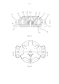
[0022] A Figura 1 representa um freio de máquina de acordo com a invenção para uma máquina de içamento de elevador[0022] Figure 1 represents a machine brake according to the invention for an elevator lifting machine
[0023] A Figura 2 representa o freio de máquina da Figura 1 na vista de topo.[0023] Figure 2 represents the machine brake of Figure 1 in top view.
[0024] A Figura 3 representa uma placa amortecedora do freio usada no freio de máquina das Figuras 1 e 2.[0024] Figure 3 represents a brake damping plate used in the machine brake of Figures 1 and 2.
[0025] As Figuras 4a, 4b, 4c apresentam ilustrações mais detalhadas de alguns projetos geométricos possíveis das contrafaces no freio eletromagnético da invenção.[0025] Figures 4a, 4b, 4c present more detailed illustrations of some possible geometric designs of the counterfaces in the electromagnetic brake of the invention.
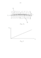
[0026] A Figura 5 visualiza um gráfico da força de amortecimento Fd como uma função de flexão x da placa amortecedora.Descrição Detalhada das Modalidades Preferidas da Invenção[0026] Figure 5 displays a graph of the damping force Fd as a function of bending x of the damper plate. Detailed Description of Preferred Embodiments of the Invention
[0027] Na Figura 1, o freio de máquina para uma máquina de içamento de elevador apresentada na Figura 2 é ilustrado na vista em seção transversal ao longo da linha A - A. A parte da armação 1 do freio de máquina é presa por alhetas de encaixe 14 à armação da máquina estacionária da máquina de içamento. A parte da armação 1 é fornecida com um eletroímã, compreendendo uma bobina magnetizante 5 e um núcleo da bobina 6 feito de ferro. A parte de armadura 2 do freio de máquina é presa de maneira móvel à parte da armação 1 com uma cavilha 15 e uma luva 12 ao redor da cavilha 15, para que a parte de armadura 2 possa se mover ao longo de um percurso determinado com relação à parte da armação 1. Ao mover a luva 12 ao longo da cavilha 15, também é possível ajustar a distância do movimento da parte de armadura 2, desse modo, ajustando a folga 10 entre a parte de armadura 2 e a parte da armação 1. As molas 4 aplicam uma força de pressionar entre a parte da armação 1 e a parte de armadura 2, para que o freio seja ativado para frear a ação da parte giratória da máquina de içamento quando as molas 4 pressionam a parte de armadura 2 contra o tambor do freio 13 da parte giratória da máquina de içamento. A faixa de ação das molas 4 é então projetada tal que a força de pressionar gerada pelas molas 4 é constante com relação ao percurso da parte de armadura 2 ou que apenas uma pequena alteração na força de pressionar ocorre quando a posição da parte de armadura 2 muda. O freio é liberado ao fornecer corrente para a bobina magnetizante 5 do eletroímã; a corrente que flui na bobina 5 produz uma força de atração entre o núcleo da bobina 6 e o núcleo magnético 3 da parte de armadura feito de material magnetizável, assim, puxando a parte de armadura 2 para fora do contato com o tambor do freio 13 ao se opor à força de pressionar das molas 4.[0027] In Figure 1, the machine brake for an elevator lifting machine shown in Figure 2 is illustrated in cross-sectional view along line A - A. The frame part 1 of the machine brake is secured by fins fitting 14 to the frame of the stationary machine of the lifting machine. The frame part 1 is provided with an electromagnet, comprising a magnetizing coil 5 and a
[0028] Quando o freio é liberado e a parte de armadura 2 começa a se mover em direção à parte da armação 1, a força de atração aplicada na parte de armadura 2 pelo eletroímã começa a crescer, porque a folga 10 entre o núcleo da bobina 6 e o núcleo magnético 3 no circuito magnético do freio começa a diminuir ao mesmo tempo. O problema é que, devido à crescente força de atração, a energia cinética da parte de armadura 2 tende a crescer muito, o que resultaria em um impacto barulhento da parte de armadura 2 contra a parte da armação 1 do freio.[0028] When the brake is released and the armature part 2 starts to move towards the armature part 1, the attraction force applied to the armature part 2 by the electromagnet starts to grow, because the
[0029] Para solucionar este problema, uma placa amortecedora 7 feita de aço para mola foi montada na folga 10 entre o núcleo da bobina 6 e o núcleo magnético 3, vide Figura 1. A contraface 8 do núcleo da bobina 6 adjacente à folga 10 foi feita um tanto côncava, e, de maneira correspondente, a contraface 9 do núcleo magnético 3 da parte de armadura adjacente à folga foi feita um tanto convexa. Consequentemente, à medida que a parte de armadura 2 se move em direção à parte da armação 1 quando o freio está sendo liberado, a placa amortecedora 7 tende a se curvar de tal maneira que a parte da borda 16 da placa amortecedora é curvada com relação à parte intermediária 17. A placa amortecedora resiste ao curvamento com a força Fd, que é proporcional à grandeza da flexão x, vide Figura 5. A força Fd cresce rapidamente à medida que flexão avança e a parte de armadura 2 se aproxima da parte da armação. A força também age na direção oposta com relação ao movimento da parte de armadura 2, então, a força Fd tende a resistir ao contato entre as contrafaces 8, 9 da parte da armação 1 e da parte de armadura 2, desse modo, amortecendo, efetivamente, o ruído perturbador produzido pelo impacto entre a parte de armadura 2 e a parte da armação 1.[0029] To solve this problem, a damper plate 7 made of spring steel was mounted in the
[0030] A Figura 3 representa a placa amortecedora circular 7 usada nos freios de máquina das Figuras 1 e 2, retratados na vista de topo. O diâmetro da placa amortecedora 7 é substancialmente igual ao diâmetro D das contrafaces 8, 9 da parte da armação 1 e da parte de armadura 2 adjacentes à folga 10, vide Figura 1. A flexão da placa amortecedora 7 ocorre de tal modo que a parte da beirada 16 da placa amortecedora é curvada com relação à parte intermediária 17. Assim, a força Fd aplicada pela placa amortecedora 7 é distribuída de maneira uniforme por todo o comprimento da parte da beirada 16 e, por outro lado, na parte intermediária 17 da placa amortecedora a força é distribuída de maneira uniforme em uma área máxima; consequentemente, a pressão aplicada nas superfícies pressionadas umas contra as outras quando a placa amortecedora 7 é curvada permanece baixa. Além do mais, a placa amortecedora 7 enche, amplamente, a folga 10 entre a parte da armação 1 e a parte de armadura 2. Conforme a placa amortecedora 7 é feita de material magnetizável, a folga efetiva do círculo magnético do freio é reduzida, a relutância do círculo magnético é reduzida e a exigência da corrente da bobina magnetizante 5 é reduzida também. A placa amortecedora 7 é fornecida com um orifício 11 em que a cavilha 15 e a luva 12 são colocadas, para que, juntas com as molas 4 que pressionam contra a placa amortecedora 7, elas centralizem a placa amortecedora 7 na posição da folga 10.[0030] Figure 3 represents the circular cushion plate 7 used in the machine brakes of Figures 1 and 2, pictured in the top view. The diameter of the damper plate 7 is substantially equal to the diameter D of the
[0031] As Figuras 4a, 4b e 4c visualizam alguns projetos geométricos que podem ser usados na moldagem das contrafaces 8, 9 do núcleo da bobina 6 e do núcleo magnético 3 do freio, adjacente à folga. Nas figuras, determinadas características, como convexidade/concavidade da contraface, são exageradas para visualizar o princípio de funcionamento.[0031] Figures 4a, 4b and 4c show some geometric designs that can be used in molding the
[0032] Na solução da Figura 4a, a contraface 8 do núcleo da bobina 6 adjacente à folga 10 foi chanfrada para um formato côncavo e a contraface 9 do núcleo magnético 3 adjacente à folga 10 foi chanfrada para um formato convexo, de tal maneira que os ângulos da chanfradura α são iguais em ambas as contrafaces. Na solução da Figura 4b, a contraface 8 do núcleo da bobina 6 adjacente à folga 10 foi chanfrada para um formato côncavo enquanto a contraface 9 do núcleo magnético 3 adjacente à folga 10 é plana; no entanto, neste caso, o diâmetro D' da contraface 9 do núcleo magnético 3 é substancialmente menor do que o diâmetro D da contraface 8 do núcleo da bobina 6 e aquele da placa amortecedora 7. Na solução da Figura 4c, a placa amortecedora 7 foi pré-tensionada a partir de sua posição de repouso para que a placa amortecedora 7 esteja em uma posição ligeiramente curvada mesmo quando o freio estiver no estado ativado. A "posição de repouso" da placa amortecedora 7 refere-se, então, a uma posição na qual a placa amortecedora 7 está em um estado não flexionado (Figuras 4a, 4b).[0032] In the solution of Figure 4a, the
[0033] As soluções das Figuras 4a a 4c também poderiam ser implementadas de outro modo, ao empregar uma disposição em que a contraface 9 do núcleo magnético 3 adjacente à folga 10 é côncava e a contraface 8 do núcleo da bobina 6 adjacente à folga 10 nas modalidades das Figuras 4a e 4c é convexa, e em que a contraface 8 do núcleo da bobina 6 adjacente à folga 10 na modalidade da Figura 4b é plana e tem um diâmetro menor do que o diâmetro D da contraface 9 do núcleo magnético 3 adjacente à folga 10 e aquele da placa amortecedora 7.[0033] The solutions of Figures 4a to 4c could also be implemented in another way, by employing an arrangement in which the
[0034] É obvio para uma pessoa versada na técnica que diferentes modalidades da invenção não são limitadas aos exemplos descritos acima, mas que elas podem ser variadas dentro do escopo das reivindicações apresentadas abaixo.[0034] It is obvious to a person skilled in the art that different embodiments of the invention are not limited to the examples described above, but that they may be varied within the scope of the claims presented below.
[0035] É adicionalmente óbvio para a pessoa versada que a solução de amortecimento da invenção é aplicável para o uso tanto nos freios a tambor quanto nos freios a disco.[0035] It is additionally obvious to the skilled person that the damping solution of the invention is applicable for use in both drum and disc brakes.
Claims (11)
Applications Claiming Priority (3)
| Application Number | Priority Date | Filing Date | Title |
|---|---|---|---|
| FI20115463 | 2011-05-12 | ||
| FI20115463A FI125108B (en) | 2011-05-12 | 2011-05-12 | Brake and method of making the brake |
| PCT/FI2012/050436 WO2012152998A2 (en) | 2011-05-12 | 2012-05-04 | A brake and a method for making a brake |
Publications (2)
| Publication Number | Publication Date |
|---|---|
| BR112013028750A2 BR112013028750A2 (en) | 2017-01-31 |
| BR112013028750B1 true BR112013028750B1 (en) | 2021-06-15 |
Family
ID=44071590
Family Applications (1)
| Application Number | Title | Priority Date | Filing Date |
|---|---|---|---|
| BR112013028750-0A BR112013028750B1 (en) | 2011-05-12 | 2012-05-04 | BRAKE AND METHOD FOR MAKING A BRAKE |
Country Status (14)
| Country | Link |
|---|---|
| US (1) | US9638272B2 (en) |
| EP (1) | EP2707618B1 (en) |
| JP (1) | JP6016894B2 (en) |
| CN (1) | CN103518073B (en) |
| AU (1) | AU2012252276B2 (en) |
| BR (1) | BR112013028750B1 (en) |
| CA (1) | CA2832676C (en) |
| ES (1) | ES2702234T3 (en) |
| FI (1) | FI125108B (en) |
| HK (1) | HK1192301A1 (en) |
| MX (1) | MX348832B (en) |
| PL (1) | PL2707618T3 (en) |
| RU (1) | RU2601488C2 (en) |
| WO (1) | WO2012152998A2 (en) |
Families Citing this family (15)
| Publication number | Priority date | Publication date | Assignee | Title |
|---|---|---|---|---|
| FI20115145L (en) * | 2011-02-15 | 2012-08-16 | Kone Corp | Attachment contact surface for a machine brake and machine brake |
| US10179094B2 (en) | 2012-09-27 | 2019-01-15 | Bayer Healthcare Llc | Foaming skincare formulations |
| US20160207693A1 (en) | 2013-07-31 | 2016-07-21 | Bayer Consumer Care Ag | Actuator assembly for a pressurized plastic vessel |
| FI124983B (en) | 2013-10-29 | 2015-04-15 | Kone Corp | Damping Arrangement to Mute the Opening Sound of the Lift of the Lifting Machine, the Lifting Machine and the Elevator |
| DE102014103837B4 (en) * | 2014-03-20 | 2015-12-17 | Kendrion (Villingen) Gmbh | Electromagnetic brake or clutch device with damping means for improved noise reduction |
| FI126171B (en) | 2014-06-19 | 2016-07-29 | Kone Corp | System, machine brake and procedure for controlling a machine brake |
| CN107098286B (en) | 2016-02-22 | 2021-05-11 | 奥的斯电梯公司 | Elevator brake and method for replacing shock pad of elevator brake |
| CN206429585U (en) * | 2016-12-13 | 2017-08-22 | 深圳市威捷机电股份公司 | Brake component in electro-magnetic braking device |
| US10214382B2 (en) | 2017-01-11 | 2019-02-26 | Otis Elevator Company | Disk damping device |
| DE102017000846B4 (en) * | 2017-01-31 | 2022-06-02 | Sew-Eurodrive Gmbh & Co Kg | Electromagnetically actuable brake arrangement for braking a rotatably mounted shaft |
| US10288133B1 (en) * | 2017-12-06 | 2019-05-14 | Warner Electric Technology Llc | Rotational coupling device having means for sealing the interface between the armature and the electromagnet |
| WO2019219243A1 (en) * | 2018-05-14 | 2019-11-21 | Sew-Eurodrive Gmbh & Co. Kg | Brake assembly for an electric motor |
| DE102018008899A1 (en) * | 2018-11-13 | 2020-05-14 | Chr. Mayr Gmbh + Co. Kg | Brake with an integral damper structure |
| EP3677539B1 (en) | 2019-01-07 | 2021-08-04 | KONE Corporation | An elevator machinery brake |
| CN114526296B (en) * | 2022-03-11 | 2023-03-24 | 哈尔滨工业大学 | Electromagnetic type does not have return clearance and loses electric brake |
Family Cites Families (27)
| Publication number | Priority date | Publication date | Assignee | Title |
|---|---|---|---|---|
| DE2840565A1 (en) | 1978-09-18 | 1980-03-20 | Siemens Ag | ELECTROMAGNETICALLY ACTUATED BRAKE |
| JPS55100425A (en) * | 1979-01-25 | 1980-07-31 | Dana Corp | Joint device |
| DE3231279A1 (en) * | 1982-08-23 | 1984-02-23 | Knorr-Bremse GmbH, 8000 München | BRAKE PAD CARRIER FOR PARTIAL DISC BRAKES, ESPECIALLY OF RAIL VEHICLES |
| DE3317913A1 (en) * | 1983-05-17 | 1984-11-22 | Knorr-Bremse GmbH, 8000 München | BRAKE PAD CARRIER FOR PARTIAL PAD DISC BRAKES |
| JPH0735829B2 (en) * | 1989-08-18 | 1995-04-19 | 株式会社日立製作所 | elevator |
| ATE116413T1 (en) * | 1990-07-12 | 1995-01-15 | Inventio Ag | SAFETY DISC BRAKE FOR ELEVATORS. |
| DE4126672C2 (en) * | 1991-08-13 | 1997-10-23 | Sew Eurodrive Gmbh & Co | Electromagnetically operated brake |
| JPH08284979A (en) * | 1995-04-11 | 1996-11-01 | Kofu Meidensha:Kk | Electromagnetic brake |
| DE19622983C1 (en) | 1996-06-08 | 1997-11-20 | Sew Eurodrive Gmbh & Co | Electromagnetically operated brake |
| DE29706124U1 (en) * | 1996-06-29 | 1997-06-12 | Brinkmann Kg H | Spring pressure brake |
| DE19838658C1 (en) * | 1998-05-14 | 2000-03-02 | Sew Eurodrive Gmbh & Co | Electromagnetically actuated brake, in particular for an electric motor |
| EP0957281A3 (en) * | 1998-05-14 | 2001-06-27 | SEW-EURODRIVE GMBH & CO. | Electromagnetically actuated brake especially for an electric motor |
| FI106255B (en) * | 1998-12-23 | 2000-12-29 | Kone Corp | Holding brake for drive disc lift |
| DE19925173C2 (en) * | 1999-06-01 | 2002-05-08 | Kendrion Binder Magnete Gmbh | Pole friction brake or pole friction clutch |
| DE19935521C2 (en) * | 1999-07-28 | 2001-07-19 | Kone Corp | Method for controlling the brake (s) of an escalator or moving walk |
| EP1232082B1 (en) | 1999-11-16 | 2004-02-18 | Continental Teves AG & Co. oHG | Electromagnet valve |
| FI117700B (en) * | 2000-05-11 | 2007-01-31 | Kone Corp | Lift holding brake and operating the brake release device |
| DE10258505A1 (en) * | 2002-12-14 | 2004-07-01 | Zf Friedrichshafen Ag | Electromagnetically actuated gear brake |
| US7063190B1 (en) | 2003-09-09 | 2006-06-20 | Mpc Products Corporation | Braking system |
| FI115719B (en) * | 2003-11-24 | 2005-06-30 | Kone Corp | Brake and procedure for setting the brake |
| CN101052584B (en) * | 2004-11-01 | 2011-06-08 | 奥蒂斯电梯公司 | Disk brake of elevator having damping |
| WO2007029310A1 (en) * | 2005-09-06 | 2007-03-15 | Mitsubishi Denki Kabushiki Kaisha | Brake device for elevator |
| KR101573552B1 (en) * | 2007-11-14 | 2015-12-11 | 인벤티오 아게 | Lift drive and method for driving and detaining a lift car, a corresponding method and a braking device, and method for decelerating and detaining a lift car, and an associated method |
| FI121994B (en) * | 2009-09-25 | 2011-07-15 | Kone Corp | Machinery brake |
| US20120000742A1 (en) * | 2010-07-02 | 2012-01-05 | Sepac, Inc. | Laminated armature for torque modulation of spring-engaged brake or clutch |
| FI20115547A0 (en) * | 2011-06-07 | 2011-06-07 | Kone Corp | Method and arrangement for adjusting the brake |
| KR101408092B1 (en) * | 2013-02-19 | 2014-06-19 | 주식회사 고영테크놀러지 | Magnetic brake |
-
2011
- 2011-05-12 FI FI20115463A patent/FI125108B/en active IP Right Grant
-
2012
- 2012-05-04 CA CA2832676A patent/CA2832676C/en active Active
- 2012-05-04 CN CN201280022770.5A patent/CN103518073B/en active Active
- 2012-05-04 PL PL12782268T patent/PL2707618T3/en unknown
- 2012-05-04 BR BR112013028750-0A patent/BR112013028750B1/en active IP Right Grant
- 2012-05-04 EP EP12782268.2A patent/EP2707618B1/en active Active
- 2012-05-04 WO PCT/FI2012/050436 patent/WO2012152998A2/en active Application Filing
- 2012-05-04 ES ES12782268T patent/ES2702234T3/en active Active
- 2012-05-04 MX MX2013013118A patent/MX348832B/en active IP Right Grant
- 2012-05-04 RU RU2013147737/11A patent/RU2601488C2/en active
- 2012-05-04 AU AU2012252276A patent/AU2012252276B2/en active Active
- 2012-05-04 JP JP2014509777A patent/JP6016894B2/en active Active
-
2013
- 2013-10-25 US US14/063,133 patent/US9638272B2/en active Active
-
2014
- 2014-06-11 HK HK14105519.5A patent/HK1192301A1/en unknown
Also Published As
| Publication number | Publication date |
|---|---|
| WO2012152998A2 (en) | 2012-11-15 |
| US20140048359A1 (en) | 2014-02-20 |
| CA2832676C (en) | 2018-01-16 |
| JP6016894B2 (en) | 2016-10-26 |
| MX348832B (en) | 2017-06-30 |
| WO2012152998A3 (en) | 2013-01-03 |
| FI125108B (en) | 2015-06-15 |
| CA2832676A1 (en) | 2012-11-15 |
| HK1192301A1 (en) | 2014-08-15 |
| PL2707618T3 (en) | 2019-04-30 |
| ES2702234T3 (en) | 2019-02-28 |
| AU2012252276A1 (en) | 2013-10-24 |
| EP2707618A2 (en) | 2014-03-19 |
| EP2707618B1 (en) | 2018-12-05 |
| FI20115463A (en) | 2012-11-13 |
| US9638272B2 (en) | 2017-05-02 |
| CN103518073B (en) | 2016-08-17 |
| BR112013028750A2 (en) | 2017-01-31 |
| CN103518073A (en) | 2014-01-15 |
| EP2707618A4 (en) | 2015-12-16 |
| JP2014513781A (en) | 2014-06-05 |
| FI20115463L (en) | 2012-11-13 |
| MX2013013118A (en) | 2014-02-20 |
| AU2012252276B2 (en) | 2017-02-16 |
| RU2013147737A (en) | 2015-06-20 |
| RU2601488C2 (en) | 2016-11-10 |
| FI20115463A0 (en) | 2011-05-12 |
Similar Documents
| Publication | Publication Date | Title |
|---|---|---|
| BR112013028750B1 (en) | BRAKE AND METHOD FOR MAKING A BRAKE | |
| JP4418231B2 (en) | Compression spring type electromagnetic brake device having a buffer member of variable spring constant | |
| KR20150118973A (en) | Floating type brake pad for train | |
| US7699145B2 (en) | Elevator disk brake with damping | |
| ES2668894T3 (en) | Friction lining support plate | |
| DK164424B (en) | NOISE ELECTROMAGNET | |
| JP5495811B2 (en) | Elevator hoist brake | |
| JP2015155348A (en) | Elevator and hoisting machine of the same | |
| KR101217096B1 (en) | Brake apparatus for adjustable brake pad gap | |
| JP2008120524A (en) | Electromagnetic brake device of hoisting machine for elevator | |
| CN110835065B (en) | Elevator braking device and elevator system | |
| JP2015089840A (en) | Electromagnetic brake device, hoist and elevator device | |
| KR20170030813A (en) | Disc brake | |
| CN204852087U (en) | Brake | |
| CN102401047A (en) | Elastic support sheet | |
| KR200460062Y1 (en) | apparatus for functioning a lever of disk brake system | |
| KR100502515B1 (en) | Disc brake and Pad shim | |
| JPH0461214B2 (en) | ||
| JP2006112506A (en) | Disc brake | |
| ES2472342B1 (en) | Electromagnetic brake device, electric drive unit comprising said device, lifting apparatus comprising said unit and method for reducing noise in said device. | |
| KR20170019657A (en) | Disc brake | |
| JP2007016832A (en) | Brake for electric motor braking | |
| KR20130143635A (en) | Anti-shock braking system |
Legal Events
| Date | Code | Title | Description |
|---|---|---|---|
| B06F | Objections, documents and/or translations needed after an examination request according [chapter 6.6 patent gazette] | ||
| B06U | Preliminary requirement: requests with searches performed by other patent offices: procedure suspended [chapter 6.21 patent gazette] | ||
| B09A | Decision: intention to grant [chapter 9.1 patent gazette] | ||
| B16A | Patent or certificate of addition of invention granted [chapter 16.1 patent gazette] |
Free format text: PRAZO DE VALIDADE: 20 (VINTE) ANOS CONTADOS A PARTIR DE 04/05/2012, OBSERVADAS AS CONDICOES LEGAIS. |