RU2601488C2 - Electromagnetic brake, brake and method for making brake - Google Patents
Electromagnetic brake, brake and method for making brake Download PDFInfo
- Publication number
- RU2601488C2 RU2601488C2 RU2013147737/11A RU2013147737A RU2601488C2 RU 2601488 C2 RU2601488 C2 RU 2601488C2 RU 2013147737/11 A RU2013147737/11 A RU 2013147737/11A RU 2013147737 A RU2013147737 A RU 2013147737A RU 2601488 C2 RU2601488 C2 RU 2601488C2
- Authority
- RU
- Russia
- Prior art keywords
- brake
- damping plate
- bending
- mating surfaces
- damping
- Prior art date
Links
- 238000000034 method Methods 0.000 title claims abstract description 5
- 238000013016 damping Methods 0.000 claims abstract description 84
- 238000005452 bending Methods 0.000 claims abstract description 40
- 230000013011 mating Effects 0.000 claims abstract description 32
- 238000004519 manufacturing process Methods 0.000 claims abstract description 6
- 230000003014 reinforcing effect Effects 0.000 claims description 62
- 230000009471 action Effects 0.000 claims description 4
- 229910000639 Spring steel Inorganic materials 0.000 claims description 3
- 230000000694 effects Effects 0.000 abstract 1
- 239000000126 substance Substances 0.000 abstract 1
- 230000007423 decrease Effects 0.000 description 9
- 239000000463 material Substances 0.000 description 5
- 230000003993 interaction Effects 0.000 description 3
- 239000002184 metal Substances 0.000 description 3
- 229910052751 metal Inorganic materials 0.000 description 3
- XEEYBQQBJWHFJM-UHFFFAOYSA-N Iron Chemical compound [Fe] XEEYBQQBJWHFJM-UHFFFAOYSA-N 0.000 description 2
- 238000013459 approach Methods 0.000 description 2
- 229920002635 polyurethane Polymers 0.000 description 2
- 239000004814 polyurethane Substances 0.000 description 2
- RYGMFSIKBFXOCR-UHFFFAOYSA-N Copper Chemical compound [Cu] RYGMFSIKBFXOCR-UHFFFAOYSA-N 0.000 description 1
- 229910000831 Steel Inorganic materials 0.000 description 1
- 230000002238 attenuated effect Effects 0.000 description 1
- 230000008859 change Effects 0.000 description 1
- 229910052802 copper Inorganic materials 0.000 description 1
- 239000010949 copper Substances 0.000 description 1
- 230000001419 dependent effect Effects 0.000 description 1
- 230000006866 deterioration Effects 0.000 description 1
- 210000005069 ears Anatomy 0.000 description 1
- 239000013013 elastic material Substances 0.000 description 1
- 229920001971 elastomer Polymers 0.000 description 1
- 238000005516 engineering process Methods 0.000 description 1
- 229910052742 iron Inorganic materials 0.000 description 1
- 238000003825 pressing Methods 0.000 description 1
- 230000009467 reduction Effects 0.000 description 1
- 230000002787 reinforcement Effects 0.000 description 1
- 239000010959 steel Substances 0.000 description 1
- 230000001629 suppression Effects 0.000 description 1
- 238000009827 uniform distribution Methods 0.000 description 1
Images
Classifications
-
- F—MECHANICAL ENGINEERING; LIGHTING; HEATING; WEAPONS; BLASTING
- F16—ENGINEERING ELEMENTS AND UNITS; GENERAL MEASURES FOR PRODUCING AND MAINTAINING EFFECTIVE FUNCTIONING OF MACHINES OR INSTALLATIONS; THERMAL INSULATION IN GENERAL
- F16D—COUPLINGS FOR TRANSMITTING ROTATION; CLUTCHES; BRAKES
- F16D55/00—Brakes with substantially-radial braking surfaces pressed together in axial direction, e.g. disc brakes
- F16D55/02—Brakes with substantially-radial braking surfaces pressed together in axial direction, e.g. disc brakes with axially-movable discs or pads pressed against axially-located rotating members
- F16D55/04—Brakes with substantially-radial braking surfaces pressed together in axial direction, e.g. disc brakes with axially-movable discs or pads pressed against axially-located rotating members by moving discs or pads away from one another against radial walls of drums or cylinders
- F16D55/06—Brakes with substantially-radial braking surfaces pressed together in axial direction, e.g. disc brakes with axially-movable discs or pads pressed against axially-located rotating members by moving discs or pads away from one another against radial walls of drums or cylinders without self-tightening action
-
- F—MECHANICAL ENGINEERING; LIGHTING; HEATING; WEAPONS; BLASTING
- F16—ENGINEERING ELEMENTS AND UNITS; GENERAL MEASURES FOR PRODUCING AND MAINTAINING EFFECTIVE FUNCTIONING OF MACHINES OR INSTALLATIONS; THERMAL INSULATION IN GENERAL
- F16D—COUPLINGS FOR TRANSMITTING ROTATION; CLUTCHES; BRAKES
- F16D65/00—Parts or details
- F16D65/0006—Noise or vibration control
-
- F—MECHANICAL ENGINEERING; LIGHTING; HEATING; WEAPONS; BLASTING
- F16—ENGINEERING ELEMENTS AND UNITS; GENERAL MEASURES FOR PRODUCING AND MAINTAINING EFFECTIVE FUNCTIONING OF MACHINES OR INSTALLATIONS; THERMAL INSULATION IN GENERAL
- F16D—COUPLINGS FOR TRANSMITTING ROTATION; CLUTCHES; BRAKES
- F16D55/00—Brakes with substantially-radial braking surfaces pressed together in axial direction, e.g. disc brakes
- F16D55/02—Brakes with substantially-radial braking surfaces pressed together in axial direction, e.g. disc brakes with axially-movable discs or pads pressed against axially-located rotating members
- F16D55/04—Brakes with substantially-radial braking surfaces pressed together in axial direction, e.g. disc brakes with axially-movable discs or pads pressed against axially-located rotating members by moving discs or pads away from one another against radial walls of drums or cylinders
- F16D55/06—Brakes with substantially-radial braking surfaces pressed together in axial direction, e.g. disc brakes with axially-movable discs or pads pressed against axially-located rotating members by moving discs or pads away from one another against radial walls of drums or cylinders without self-tightening action
- F16D55/08—Mechanically-actuated brakes
-
- B—PERFORMING OPERATIONS; TRANSPORTING
- B66—HOISTING; LIFTING; HAULING
- B66B—ELEVATORS; ESCALATORS OR MOVING WALKWAYS
- B66B1/00—Control systems of elevators in general
- B66B1/24—Control systems with regulation, i.e. with retroactive action, for influencing travelling speed, acceleration, or deceleration
- B66B1/28—Control systems with regulation, i.e. with retroactive action, for influencing travelling speed, acceleration, or deceleration electrical
- B66B1/32—Control systems with regulation, i.e. with retroactive action, for influencing travelling speed, acceleration, or deceleration electrical effective on braking devices, e.g. acting on electrically controlled brakes
-
- B—PERFORMING OPERATIONS; TRANSPORTING
- B66—HOISTING; LIFTING; HAULING
- B66B—ELEVATORS; ESCALATORS OR MOVING WALKWAYS
- B66B5/00—Applications of checking, fault-correcting, or safety devices in elevators
- B66B5/02—Applications of checking, fault-correcting, or safety devices in elevators responsive to abnormal operating conditions
- B66B5/16—Braking or catch devices operating between cars, cages, or skips and fixed guide elements or surfaces in hoistway or well
-
- F—MECHANICAL ENGINEERING; LIGHTING; HEATING; WEAPONS; BLASTING
- F16—ENGINEERING ELEMENTS AND UNITS; GENERAL MEASURES FOR PRODUCING AND MAINTAINING EFFECTIVE FUNCTIONING OF MACHINES OR INSTALLATIONS; THERMAL INSULATION IN GENERAL
- F16D—COUPLINGS FOR TRANSMITTING ROTATION; CLUTCHES; BRAKES
- F16D13/00—Friction clutches
- F16D13/22—Friction clutches with axially-movable clutching members
-
- F—MECHANICAL ENGINEERING; LIGHTING; HEATING; WEAPONS; BLASTING
- F16—ENGINEERING ELEMENTS AND UNITS; GENERAL MEASURES FOR PRODUCING AND MAINTAINING EFFECTIVE FUNCTIONING OF MACHINES OR INSTALLATIONS; THERMAL INSULATION IN GENERAL
- F16D—COUPLINGS FOR TRANSMITTING ROTATION; CLUTCHES; BRAKES
- F16D13/00—Friction clutches
- F16D13/76—Friction clutches specially adapted to incorporate with other transmission parts, i.e. at least one of the clutch parts also having another function, e.g. being the disc of a pulley
-
- F—MECHANICAL ENGINEERING; LIGHTING; HEATING; WEAPONS; BLASTING
- F16—ENGINEERING ELEMENTS AND UNITS; GENERAL MEASURES FOR PRODUCING AND MAINTAINING EFFECTIVE FUNCTIONING OF MACHINES OR INSTALLATIONS; THERMAL INSULATION IN GENERAL
- F16D—COUPLINGS FOR TRANSMITTING ROTATION; CLUTCHES; BRAKES
- F16D59/00—Self-acting brakes, e.g. coming into operation at a predetermined speed
- F16D59/02—Self-acting brakes, e.g. coming into operation at a predetermined speed spring-loaded and adapted to be released by mechanical, fluid, or electromagnetic means
-
- F—MECHANICAL ENGINEERING; LIGHTING; HEATING; WEAPONS; BLASTING
- F16—ENGINEERING ELEMENTS AND UNITS; GENERAL MEASURES FOR PRODUCING AND MAINTAINING EFFECTIVE FUNCTIONING OF MACHINES OR INSTALLATIONS; THERMAL INSULATION IN GENERAL
- F16D—COUPLINGS FOR TRANSMITTING ROTATION; CLUTCHES; BRAKES
- F16D65/00—Parts or details
- F16D65/14—Actuating mechanisms for brakes; Means for initiating operation at a predetermined position
- F16D65/28—Actuating mechanisms for brakes; Means for initiating operation at a predetermined position arranged apart from the brake
-
- H—ELECTRICITY
- H02—GENERATION; CONVERSION OR DISTRIBUTION OF ELECTRIC POWER
- H02K—DYNAMO-ELECTRIC MACHINES
- H02K7/00—Arrangements for handling mechanical energy structurally associated with dynamo-electric machines, e.g. structural association with mechanical driving motors or auxiliary dynamo-electric machines
- H02K7/10—Structural association with clutches, brakes, gears, pulleys or mechanical starters
- H02K7/102—Structural association with clutches, brakes, gears, pulleys or mechanical starters with friction brakes
-
- F—MECHANICAL ENGINEERING; LIGHTING; HEATING; WEAPONS; BLASTING
- F16—ENGINEERING ELEMENTS AND UNITS; GENERAL MEASURES FOR PRODUCING AND MAINTAINING EFFECTIVE FUNCTIONING OF MACHINES OR INSTALLATIONS; THERMAL INSULATION IN GENERAL
- F16D—COUPLINGS FOR TRANSMITTING ROTATION; CLUTCHES; BRAKES
- F16D2121/00—Type of actuator operation force
- F16D2121/18—Electric or magnetic
- F16D2121/20—Electric or magnetic using electromagnets
- F16D2121/22—Electric or magnetic using electromagnets for releasing a normally applied brake
-
- F—MECHANICAL ENGINEERING; LIGHTING; HEATING; WEAPONS; BLASTING
- F16—ENGINEERING ELEMENTS AND UNITS; GENERAL MEASURES FOR PRODUCING AND MAINTAINING EFFECTIVE FUNCTIONING OF MACHINES OR INSTALLATIONS; THERMAL INSULATION IN GENERAL
- F16D—COUPLINGS FOR TRANSMITTING ROTATION; CLUTCHES; BRAKES
- F16D55/00—Brakes with substantially-radial braking surfaces pressed together in axial direction, e.g. disc brakes
- F16D55/24—Brakes with substantially-radial braking surfaces pressed together in axial direction, e.g. disc brakes with a plurality of axially-movable discs, lamellae, or pads, pressed from one side towards an axially-located member
- F16D55/26—Brakes with substantially-radial braking surfaces pressed together in axial direction, e.g. disc brakes with a plurality of axially-movable discs, lamellae, or pads, pressed from one side towards an axially-located member without self-tightening action
- F16D55/28—Brakes with only one rotating disc
-
- F—MECHANICAL ENGINEERING; LIGHTING; HEATING; WEAPONS; BLASTING
- F16—ENGINEERING ELEMENTS AND UNITS; GENERAL MEASURES FOR PRODUCING AND MAINTAINING EFFECTIVE FUNCTIONING OF MACHINES OR INSTALLATIONS; THERMAL INSULATION IN GENERAL
- F16D—COUPLINGS FOR TRANSMITTING ROTATION; CLUTCHES; BRAKES
- F16D65/00—Parts or details
- F16D65/02—Braking members; Mounting thereof
- F16D65/04—Bands, shoes or pads; Pivots or supporting members therefor
- F16D65/092—Bands, shoes or pads; Pivots or supporting members therefor for axially-engaging brakes, e.g. disc brakes
- F16D65/095—Pivots or supporting members therefor
- F16D65/097—Resilient means interposed between pads and supporting members or other brake parts
- F16D65/0971—Resilient means interposed between pads and supporting members or other brake parts transmitting brake actuation force, e.g. elements interposed between brake piston and pad
-
- F—MECHANICAL ENGINEERING; LIGHTING; HEATING; WEAPONS; BLASTING
- F16—ENGINEERING ELEMENTS AND UNITS; GENERAL MEASURES FOR PRODUCING AND MAINTAINING EFFECTIVE FUNCTIONING OF MACHINES OR INSTALLATIONS; THERMAL INSULATION IN GENERAL
- F16D—COUPLINGS FOR TRANSMITTING ROTATION; CLUTCHES; BRAKES
- F16D65/00—Parts or details
- F16D65/02—Braking members; Mounting thereof
- F16D65/04—Bands, shoes or pads; Pivots or supporting members therefor
- F16D65/092—Bands, shoes or pads; Pivots or supporting members therefor for axially-engaging brakes, e.g. disc brakes
- F16D65/095—Pivots or supporting members therefor
- F16D65/097—Resilient means interposed between pads and supporting members or other brake parts
- F16D65/0973—Resilient means interposed between pads and supporting members or other brake parts not subjected to brake forces
- F16D65/0974—Resilient means interposed between pads and supporting members or other brake parts not subjected to brake forces acting on or in the vicinity of the pad rim in a direction substantially transverse to the brake disc axis
- F16D65/0977—Springs made from sheet metal
-
- Y—GENERAL TAGGING OF NEW TECHNOLOGICAL DEVELOPMENTS; GENERAL TAGGING OF CROSS-SECTIONAL TECHNOLOGIES SPANNING OVER SEVERAL SECTIONS OF THE IPC; TECHNICAL SUBJECTS COVERED BY FORMER USPC CROSS-REFERENCE ART COLLECTIONS [XRACs] AND DIGESTS
- Y10—TECHNICAL SUBJECTS COVERED BY FORMER USPC
- Y10T—TECHNICAL SUBJECTS COVERED BY FORMER US CLASSIFICATION
- Y10T29/00—Metal working
- Y10T29/49—Method of mechanical manufacture
- Y10T29/49826—Assembling or joining
Landscapes
- Engineering & Computer Science (AREA)
- General Engineering & Computer Science (AREA)
- Mechanical Engineering (AREA)
- Automation & Control Theory (AREA)
- Physics & Mathematics (AREA)
- Electromagnetism (AREA)
- Power Engineering (AREA)
- Braking Arrangements (AREA)
- Cage And Drive Apparatuses For Elevators (AREA)
Abstract
Description
ОБЛАСТЬ ТЕХНИКИFIELD OF TECHNOLOGY
Данное изобретение относится к решениям, предназначенным для глушения создаваемого тормозом шума.This invention relates to solutions for damping brake noise.
ПРЕДПОСЫЛКИ ИЗОБРЕТЕНИЯBACKGROUND OF THE INVENTION
Тормозное устройство, обычно применяемое, например, в лебедках лифтов, представляет собой тормоз, который входит в механическое взаимодействие с вращающейся частью лебедки. Тормоз лебедки может быть изготовлен, например, в виде барабанного или дискового тормоза и приводится в действие путем прерывания подачи электрического тока к электромагниту тормоза. Как правило, тормоз лебедки содержит пружины, которые при срабатывании тормоза поджимают арматурную часть, выполненную с тормозной накладкой, к тормозящей поверхности вращающейся части с обеспечением затормаживания вращающейся части лебедки.The brake device, usually used, for example, in elevator winches, is a brake that enters into mechanical interaction with the rotating part of the winch. The winch brake can be made, for example, in the form of a drum or disk brake and is activated by interrupting the supply of electric current to the brake electromagnet. As a rule, the winch brake contains springs, which, when the brake is applied, press the reinforcing part, made with the brake lining, to the braking surface of the rotating part to ensure that the rotating part of the winch is braked.
Тормоз расцепляется путем подачи тока к электромагниту тормоза. Расцепление тормоза выполняется, когда электромагнит отодвигает тормозную накладку от тормозящей поверхности вращающейся части лебедки с противодействием толкающему усилию, создаваемому пружинами. Во время работы лифта электромагнит остается в состоянии соединения с источником питания, так что тормоз находится в расцепленном состоянии, и кабина лифта может перемещаться вверх или вниз в шахте лифта. Тормозное устройство лифта может быть выполнено, например, таким образом, что одна лебедка содержит два или более тормозов.The brake disengages by applying current to the brake solenoid. The brake is released when the electromagnet moves the brake lining away from the braking surface of the rotating part of the winch, counteracting the pushing force generated by the springs. During the operation of the elevator, the electromagnet remains in a state of connection with the power source, so that the brake is disengaged, and the elevator car can move up or down in the elevator shaft. The brake device of the elevator can be performed, for example, in such a way that one winch contains two or more brakes.
При уменьшении тока, проходящего через электромагнит, усилие, прикладываемое пружиной, в конце концов превышает силу притяжения электромагнита, и тормоз приводится в действие. В результате нарушения равновесия сил тормозная накладка ударяет по тормозящей поверхности вращающейся части лебедки. При расцеплении тормоза электромагнит снова прикладывает к арматурной части усилие, противодействующее усилию пружины. Когда усилие, прикладываемое электромагнитом к арматурной части, достигает величины, превышающей усилие пружины, воздушный зазор между рамной частью и арматурной частью смыкается, и арматурная часть соударяется с рамной частью.With a decrease in the current passing through the electromagnet, the force exerted by the spring ultimately exceeds the attractive force of the electromagnet, and the brake is applied. As a result of the imbalance of forces, the brake lining strikes the braking surface of the rotating part of the winch. When the brake is released, the electromagnet again applies a force to the reinforcing part, which counteracts the spring force. When the force applied by the electromagnet to the reinforcing part reaches a value exceeding the spring force, the air gap between the frame part and the reinforcing part closes, and the reinforcing part collides with the frame part.
Соударение, возникающее между металлическими частями тормоза после срабатывания или расцепления тормоза, может создавать неприятный шум. Были предприняты попытки решить проблему возникновения шума путем установки (например, в воздушном зазоре между рамной и арматурной частями) отдельного демпфирующего устройства, которое при нахождении тормоза в расцепленном состоянии препятствует непосредственному контакту между металлическими поверхностями рамной и арматурной частей. Демпфирующее устройство может быть изготовлено из эластичного материала, например резины или полиуретана, и может быть выполнено в виде пружины, предназначенной для выполнения данной задачи, например цилиндрической пружины или диафрагменной пружины.A collision that occurs between the metal parts of the brake after the brake is released or disengaged can create an unpleasant noise. Attempts have been made to solve the problem of noise by installing (for example, in the air gap between the frame and reinforcing parts) a separate damping device, which, when the brake is in the disengaged state, prevents direct contact between the metal surfaces of the frame and reinforcing parts. The damping device can be made of an elastic material, such as rubber or polyurethane, and can be made in the form of a spring designed to perform this task, for example a coil spring or a diaphragm spring.
Воздушный зазор между рамной частью и арматурной частью может варьироваться вследствие, например, допусков на изготовление демпфирующего устройства. Сила притяжения электромагнита уменьшается при увеличении воздушного зазора, а это значит, что для расцепления тормоза/удерживания тормоза в расцепленном состоянии необходимо повышенное значение электрического тока. В целом, потери мощности в катушке электромагнита увеличиваются с увеличением воздушного зазора, а при увеличении потерь мощности также повышается рабочая температура тормоза.The air gap between the frame part and the reinforcing part may vary due to, for example, tolerances for the manufacture of a damping device. The force of attraction of the electromagnet decreases with increasing air gap, which means that to release the brake / hold the brake in the disengaged state, an increased value of the electric current is necessary. In general, power losses in an electromagnet coil increase with increasing air gap, and with increasing power losses, the operating temperature of the brake also increases.
Кроме того, демпфирующая мощность, обеспечиваемая демпфирующим устройством, может уменьшаться с течением срока службы тормоза, например, демпфирующая мощность устройства, изготовленного из полиуретана, может постепенно снижаться вследствие воздействия высокой температуры. К тому же, помимо прочего, демпфирующая мощность пружины может уменьшаться вследствие усталостных нагрузок. Уменьшение демпфирующей мощности предполагает ухудшение функциональной способности демпфера, то есть его способности к гашению шума, создаваемого тормозом.In addition, the damping power provided by the damping device may decrease over the life of the brake, for example, the damping power of a device made of polyurethane may gradually decrease due to exposure to high temperature. In addition, among other things, the damping power of the spring may decrease due to fatigue loads. A decrease in damping power implies a deterioration in the functional ability of the damper, that is, its ability to dampen the noise generated by the brake.
ЦЕЛЬ ИЗОБРЕТЕНИЯOBJECT OF THE INVENTION
Цель изобретения заключается в создании решений, устраняющих недостатки, изложенные выше и рассмотренные в нижеприведенном описании изобретения. Согласно изобретению для достижения данной цели предложен электромагнитный тормоз по п.1, тормоз по п.3 и способ по п.13 для изготовления тормоза. Предпочтительные варианты выполнения описаны в зависимых пунктах формулы изобретения. Кроме того, в описательной части заявки и на чертежах представлены варианты выполнения и комбинации различных вариантов выполнения изобретенияThe purpose of the invention is to create solutions that eliminate the disadvantages set forth above and discussed in the description of the invention below. According to the invention, in order to achieve this goal, the electromagnetic brake according to
СУЩНОСТЬ ИЗОБРЕТЕНИЯSUMMARY OF THE INVENTION
Электромагнитный тормоз согласно изобретению содержит рамную часть, арматурную часть, установленную с возможностью перемещения на рамной части и содержащую магнитный сердечник, один или более пружинных элементов, предназначенных для приведения тормоза в действие путем перемещения арматурной части вперед, электромагнит, присоединенный к рамной части и предназначенный для расцепления тормоза путем втягивания назад магнитного сердечника и вместе с ним арматурной части с противодействием указанным одному или более пружинным элементам, и упругогибкую демпфирующую пластину, которая имеет плоскую форму в исходном положении и выполнена с возможностью изгибания под действием усилия, перемещающего арматурную часть. Более того, при изгибании демпфирующей пластины под действием усилия, перемещающего арматурную часть, указанная пластина противодействует изгибанию с созданием демпфирующего усилия, которое гасит шум, создаваемый тормозом.The electromagnetic brake according to the invention comprises a frame part, a reinforcing part mounted to be movable on the frame part and comprising a magnetic core, one or more spring elements for actuating the brake by moving the reinforcing part forward, an electromagnet connected to the frame part and intended for uncoupling the brake by pulling back the magnetic core and with it the reinforcing part to counteract the specified one or more spring elements and an elastic-flexible damping plate, which has a flat shape in the initial position and is made with the possibility of bending under the action of the force moving the reinforcing part. Moreover, when bending the damping plate under the action of the force moving the reinforcing part, this plate counteracts bending with the creation of a damping force that dampens the noise created by the brake.
Изобретение также относится к тормозу, который содержит рамную часть, арматурную часть, установленную с возможностью перемещения на рамной части, воздушный зазор между обращенными друг к другу сопряженными поверхностями рамной и арматурной частей, и упругогибкую демпфирующую пластину, установленную в указанном воздушном зазоре, имеющую плоскую форму в исходном положении и противодействующую изгибанию с созданием демпирующего усилия, которое гасит шум, создаваемый тормозом. По меньшей мере одна из указанных сопряженных поверхностей имеет неплоскую форму для обеспечения изгибания демпфирующей пластины.The invention also relates to a brake that comprises a frame part, a reinforcing part mounted to be movable on the frame part, an air gap between the mating surfaces of the frame and reinforcing parts facing each other, and an elastic-flexible damping plate mounted in the indicated air gap having a flat shape in the initial position and counteracting bending with the creation of a damping force that dampens the noise created by the brake. At least one of these mating surfaces has a non-planar shape to allow bending of the damping plate.
Предложенная демпфирующая пластина установлена с возможностью изгибания предпочтительно таким образом, что ее краевая часть изгибается относительно ее средней части. Предложенная демпфирующая пластина, имеющая плоскую форму в исходном положении, обеспечивает возможность равномерного приложения демпфирующей силы по площади тормоза, так что управление перемещением арматурной части может выполняться более точно и в пределах меньших допусков по сравнению с известным уровнем техники. Равномерное распределение демпфирующей силы также означает уменьшение точечных демпфирующих усилий, возрастание величины демпфирующего усилия и возможность выполнения тормоза с обеспечением очень короткого перемещения арматурной части. Короткое перемещение арматурной части обеспечивает возможность уменьшения кинетической энергии, соответствующей этому перемещению. При уменьшении кинетической энергии шум, создаваемый тормозом, также ослабляется. Кроме того, предложенная демпфирующая пластина может быть выполнена таким образом, что демпфирующее усилие быстро возрастает при изгибании демпфирующей пластины, даже если общий изгиб пластины невелик. Вследствие небольшого общего изгиба усталостная нагрузка, оказываемая на демпфирующую пластину, изготовленную, например, из пружинной стали, невысока, несмотря на многократное изгибание, а это означает, что срок эксплуатации демпфирующей пластины и, следовательно, срок службы тормоза будет очень большим.The proposed damping plate is mounted with the possibility of bending, preferably in such a way that its edge part is bent relative to its middle part. The proposed damping plate, having a flat shape in the initial position, provides the possibility of uniform application of damping force over the brake area, so that the movement of the reinforcing part can be controlled more accurately and within lower tolerances compared with the prior art. A uniform distribution of damping force also means a reduction in point damping forces, an increase in the value of the damping force and the possibility of performing the brake with a very short movement of the reinforcing part. A short movement of the reinforcing part makes it possible to reduce the kinetic energy corresponding to this movement. With a decrease in kinetic energy, the noise generated by the brake is also attenuated. In addition, the proposed damping plate can be designed so that the damping force increases rapidly when the damping plate is bent, even if the total bending of the plate is small. Due to the slight general bending, the fatigue load exerted on the damping plate made, for example, of spring steel, is low, despite repeated bending, which means that the life of the damping plate and, therefore, the service life of the brake will be very long.
В предпочтительном варианте выполнения изобретения демпфирующее усилие пропорционально степени изгибания демпфирующей пластины. В предпочтительном варианте выполнения изобретения при расцеплении тормоза демпфирующее усилие резко увеличивается по мере приближения арматурной части к рамной части тормоза, в результате чего обеспечивается эффективное рассеивание кинетической энергии арматурной части и противодействие контакту между рамной и арматурной частями.In a preferred embodiment, the damping force is proportional to the degree of bending of the damping plate. In a preferred embodiment of the invention, when the brake is released, the damping force increases sharply as the reinforcing part approaches the frame part of the brake, as a result of which the kinetic energy of the reinforcing part is effectively dissipated and the contact between the frame and reinforcing parts is resisted.
В предпочтительном варианте выполнения изобретения демпфирующая пластина установлена в воздушном зазоре между обращенными друг к другу сопряженными поверхностями рамной и арматурной частей. В предпочтительном варианте выполнения изобретения демпфирующая пластина изготовлена из намагничиваемого материала, предпочтительно пружиной стали. Такая демпфирующая пластина обеспечивает уменьшение эффективного воздушного зазора в магнитной цепи тормоза с созданием тем самым заданной силы притяжения между электромагнитом и магнитным сердечником при уменьшенном намагничивающем токе электромагнита. В то же время уменьшаются также потери мощности в электромагните. С другой стороны, это также позволяет уменьшить размер намагничивающей катушки, например, сократить количество медных проводов в катушке.In a preferred embodiment of the invention, a damping plate is installed in the air gap between the mating surfaces of the frame and reinforcing parts facing each other. In a preferred embodiment, the damping plate is made of a magnetizable material, preferably a steel spring. Such a damping plate provides a decrease in the effective air gap in the magnetic circuit of the brake, thereby creating a predetermined attractive force between the electromagnet and the magnetic core with a reduced magnetizing current of the electromagnet. At the same time, power losses in the electromagnet are also reduced. On the other hand, it also allows to reduce the size of the magnetizing coil, for example, to reduce the number of copper wires in the coil.
В предпочтительном варианте выполнения изобретения одна из указанных сопряженных поверхностей имеет вогнутую форму для обеспечения изгибания демпфирующей пластины. Для получения вогнутой сопряженной поверхности в ней может быть выполнен машинной обработкой, например, вырез, глубина которого определяет величину изгиба демпфирующей пластины. В предпочтительном варианте выполнения изобретения одна из указанных сопряженных поверхностей имеет выпуклую форму для обеспечения изгибания демпфирующей пластины. Для получения выпуклой сопряженной поверхности на ней может быть выполнен машинной обработкой, например, выступ или скос, высота/наклон которого определяет величину изгиба демпфирующей пластины. Область действия демпфирующего усилия и его величина в зависимости от траектории перемещения арматурной части могут быть четко определены на основании геометрии сопряженной поверхности/сопряженных поверхностей, благодаря чему полученное решение, обеспечивающее демпфирование, является очень точным в отношении как производственных, так и регулировочных допусков, что дает возможность получения короткого перемещения арматурной части и в то же время - небольшого воздушного зазора между сопряженными поверхностями.In a preferred embodiment of the invention, one of said mating surfaces is concave in order to allow the damping plate to bend. To obtain a concave mating surface, it may be machined, for example, a cutout, the depth of which determines the amount of bending of the damping plate. In a preferred embodiment of the invention, one of said mating surfaces is convex in shape to allow bending of the damping plate. To obtain a convex mating surface, it can be machined, for example, a protrusion or bevel, the height / inclination of which determines the amount of bending of the damping plate. The scope of the damping force and its value depending on the trajectory of movement of the reinforcing part can be clearly determined on the basis of the geometry of the mating surface / mating surfaces, so the resulting damping solution is very accurate with respect to both production and adjusting tolerances, which gives the possibility of obtaining a short movement of the reinforcing part and at the same time a small air gap between the mating surfaces.
Предложенный тормоз предпочтительно представляет собой тормоз лебедки для лифта, эскалатора или траволатора.The proposed brake is preferably a winch brake for an elevator, escalator or travelator.
Согласно изобретению, способ изготовления тормоза включает выполнение рамной части тормоза и арматурной части тормоза, опирающейся с возможностью перемещения на рамную часть, выполнение сопряженных поверхностей, расположенных напротив друг друга на рамной и арматурной частях, выполнение упругогибкой демпфирующей пластины, которая в исходном положении имеет плоскую форму, а при изгибании создает усилие, противодействующее изгибанию с обеспечением гашения шума, создаваемого тормозом, и установку демпфирующей пластины в воздушном зазоре между сопряженными поверхностями, расположенными в тормозе.According to the invention, the method of manufacturing the brake includes performing the brake part of the brake and the reinforcing part of the brake, which can be reliably supported on the frame part, making mating surfaces opposite each other on the frame and reinforcing parts, performing an elasticly flexible damping plate, which in the initial position has a flat shape and during bending it creates a force that counteracts bending while suppressing the noise generated by the brake and installing a damping plate in the air gap D between the mating surfaces in the brake.
В предпочтительном варианте выполнения изобретения одну из указанных сопряженных поверхностей выполняют с вогнутой формой для обеспечения изгибания демпфирующей пластины.In a preferred embodiment of the invention, one of said mating surfaces is concave in shape to allow the damping plate to bend.
В предпочтительном варианте выполнения изобретения одну из указанных сопряженных поверхностей выполняют с выпуклой формой для обеспечения изгибания демпфирующей пластины.In a preferred embodiment, one of said mating surfaces is convex in shape to allow the damping plate to bend.
В предпочтительном варианте выполнения изобретения демпфирующую пластину устанавливают в состоянии взаимодействия между арматурной и рамной частями с обеспечением изгибания демпфирующей пластины. Демпфирующая пластина может находиться в контакте как с арматурной частью, так и с рамной частью по всей длине перемещения арматурной части, или же демпфирующая пластина может быть отсоединена от арматурной части и/или рамной части на отрезке диапазона перемещения арматурной части.In a preferred embodiment of the invention, the damping plate is installed in a state of interaction between the reinforcing and the frame parts to ensure bending of the damping plate. The damping plate may be in contact with both the reinforcing part and the frame part along the entire length of the movement of the reinforcing part, or the damping plate may be disconnected from the reinforcing part and / or the frame part on a segment of the range of movement of the reinforcing part.
Демпфирующая пластина может быть выполнена в различных видах, например, она может иметь круглую (дисковидную) или квадратную форму. Жесткость демпфирующей пластины и, следовательно, усилие, противодействующее ее изгибанию, может регулироваться не только путем выбора материала, но и, например, путем изменения толщины пластины. Изгибание демпфирующей пластины может быть выполнено таким образом, что краевая часть пластины изгибается в каждой точке в равной степени относительно средней части, или же изгибание может быть выполнено с обеспечением изгибания только двух противоположных краев пластины относительно ее средней части. Демпфирующую пластину предпочтительно изготавливают из несжимаемого материала, например металла.The damping plate can be made in various forms, for example, it can have a round (disk-shaped) or square shape. The stiffness of the damping plate and, therefore, the force that counteracts its bending, can be adjusted not only by selecting the material, but, for example, by changing the thickness of the plate. The bending of the damping plate can be performed in such a way that the edge part of the plate bends at each point equally with respect to the middle part, or bending can be performed so that only two opposite edges of the plate bend with respect to its middle part. The damping plate is preferably made of an incompressible material, for example metal.
Приведенное выше краткое описание, а также дополнительные особенности и преимущества изобретения, описанные ниже, станут более понятны из нижеприведенного описания различных вариантов выполнения изобретения, которые не должны считаться ограничивающими область применения изобретения.The above brief description, as well as additional features and advantages of the invention described below, will become more apparent from the following description of various embodiments of the invention, which should not be construed as limiting the scope of the invention.
КРАТКОЕ ОПИСАНИЕ ЧЕРТЕЖЕЙBRIEF DESCRIPTION OF THE DRAWINGS
Фиг.1 изображает тормоз лебедки, выполненный согласно изобретению и предназначенный для лебедки лифта.Figure 1 depicts a winch brake, made according to the invention and intended for the elevator winch.
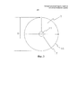
Фиг.2 изображает вид сверху тормоза, показанного на фиг.1.Figure 2 depicts a top view of the brake shown in figure 1.
Фиг.3 изображает демпфирующую пластину тормоза, применяемую в тормозе лебедки, показанном на фиг.1 и 2.Figure 3 depicts the brake damping plate used in the winch brake shown in figures 1 and 2.
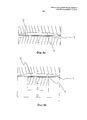
Фиг.4а, 4b, 4с изображают более подробные виды некоторых возможных геометрических конфигураций сопряженных поверхностей электромагнитного тормоза согласно изобретению.4a, 4b, 4c depict more detailed views of some possible geometric configurations of the mating surfaces of the electromagnetic brake according to the invention.
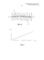
Фиг.5 изображает график зависимости демпфирующего усилия Fd в виде функции изгиба x демпфирующей пластины.5 is a graph of the damping force F d as a function of bending x of the damping plate.
ПОДРОБНОЕ ОПИСАНИЕ ПРЕДПОЧТИТЕЛЬНЫХ ВАРИАНТОВ ВЫПОЛНЕНИЯ ИЗОБРЕТЕНИЯDETAILED DESCRIPTION OF THE PREFERRED EMBODIMENTS
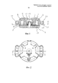
На фиг.1 изображен разрез тормоза лебедки лифта, показанного на фиг.2, по линии А-А. Рамная часть 1 тормоза прикреплена с помощью монтажных ушек 14 к неподвижной раме лебедки. Рамная часть 1 выполнена с электромагнитом, который содержит намагничивающую катушку 5 и сердечник 6 катушки, изготовленный из железа. Арматурная часть 2 тормоза с возможностью перемещения прикреплена к рамной части 1 при помощи болта 15 и расположенной вокруг него муфты 12, так что арматурная часть 2 может перемещаться вдоль заданной траектории относительно рамной части 1. Кроме того, путем перемещения муфты 12 вдоль болта 15 можно обеспечить регулирование расстояния, на которое перемещается арматурная часть 2, и, следовательно, регулирование воздушного зазора 10 между арматурной частью 2 и рамной частью 1. Пружины 4 создают толкающее усилие между рамной частью 1 и арматурной частью 2, так что когда пружины 4 поджимают арматурную часть 2 к тормозному барабану 13 вращающейся части лебедки, тормоз приводится в действие с обеспечением торможения перемещения вращающейся части лебедки. Диапазон действия пружин 4 задан таким образом, что создаваемое ими толкающее усилие является неизменным относительно траектории перемещения арматурной части 2, либо имеет место лишь незначительное изменение толкающего усилия при изменении положения арматурной части 2. Расцепление тормоза происходит вследствие приложения электрического тока к намагничивающей катушке 5 электромагнита. Ток, протекающий в катушке 5, создает силу притяжения между сердечником 6 катушки и магнитным сердечником 3 арматурной части, изготовленным из намагничиваемого материала, в результате чего происходит вытягивание арматурной части 2 из положения контакта с тормозным барабаном 13 с противодействием толкающему усилию пружин 4.Figure 1 shows a section of the brake of the elevator winch shown in figure 2, along the line aa. The
Когда тормоз расцеплен и арматурная часть 2 начинает перемещение по направлению к рамной части 1, сила притяжения, оказываемая на арматурную часть 2 со стороны электромагнита, начинает возрастать, поскольку в то же время воздушный зазор 10 между сердечником 6 катушки и магнитным сердечником 3 в магнитной цепи тормоза начинает уменьшаться. Проблема заключается в том, что вследствие увеличения силы притяжения кинетическая энергия арматурной части 2 имеет тенденцию к сильному росту, что приводит к шумному соударению арматурной части 2 с рамной частью 1 тормоза.When the brake is disengaged and the reinforcing part 2 begins to move towards the
Для решения этой проблемы в воздушный зазор 10 между сердечником 6 катушки и магнитным сердечником 3 устанавливают демпфирующую пластину 7, изготовленную из пружинной стали (см. фиг.1). Сопряженная поверхность 8 сердечника 6 катушки, смежная с воздушным зазором 10, выполнена слегка вогнутой, и, соответственно, сопряженная поверхность 9 магнитного сердечника 3 арматурной части, смежная с воздушным зазором, выполнена слегка выпуклой. Следовательно, при перемещении арматурной части 2 по направлению к рамной части 1, когда тормоз находится в расцепленном состоянии, пластина 7 стремится изогнуться таким образом, что ее краевая часть 16 изгибается относительно средней части 17. Демпфирующая пластина противодействует изгибанию с усилием Fd, которое пропорционально величине изгиба x (см. фиг.5). Усилие Fd быстро возрастает по мере увеличения изгиба, и арматурная часть 2 приближается к рамной части. Кроме того, указанное усилие действует в направлении, противоположном направлению перемещения арматурной части 2, так что усилие Fd стремится противодействовать контакту между сопряженными поверхностями 8, 9 рамной части 1 и арматурной части 2 с обеспечением эффективного гашения неприятного шума, создаваемого взаимодействием между арматурной частью 2 и рамной частью 1.To solve this problem, a damping
На фиг.3 изображен вид сверху круглой демпфирующей пластины 7, применяемой в тормозах лебедки, показанных на фиг.1 и 2. Диаметр пластины 7 по существу равен диаметру D сопряженных поверхностей 8, 9 рамной части 1 и арматурной части 2, смежных с воздушным зазором 10 (см. фиг.1). Изгибание пластины 7 происходит таким образом, что ее краевая часть 16 изгибается относительно средней части 17. Таким образом, усилие Fd, прикладываемое пластиной 7, равномерно распределено по всей длине краевой части 16, и, с другой стороны, в средней части 17 пластины усилие распределено равномерно по максимальной площади, следовательно, давление, оказываемое при изгибании пластины 7 на прижимаемые друг к другу поверхности, остается небольшим. Кроме того, пластина 7 заполняет основную часть зазора 10 между рамной частью 1 и арматурной частью 2. Поскольку пластина 7 изготовлена из намагничиваемого материала, эффективный воздушный зазор магнитной цепи тормоза уменьшен, магнитное сопротивление магнитной цепи уменьшено и требования по уровню тока намагничивающей катушки 5 также снижены. Демпфирующая пластина 7 имеет отверстие 11, в которое вставлены болт 15 и муфта 12 так, что совместно с пружинами 4, давящими на пластину 7, они обеспечивают центрирование пластины 7 на месте в зазоре 10.Figure 3 shows a top view of a circular damping
На фиг.4а, 4b и 4с показаны геометрические конфигурации, которые могут использоваться при выборе формы сопряженных поверхностей 8, 9 сердечника 6 катушки и магнитного сердечника 3 тормоза, смежных с воздушным зазором. На чертежах некоторые особенности, например выпуклость/вогнутость сопряженных поверхностей, показаны в преувеличенной степени для наглядного представления принципа работы.On figa, 4b and 4C shows the geometric configurations that can be used when choosing the shape of the mating surfaces 8, 9 of the core 6 of the coil and the magnetic core 3 of the brake adjacent to the air gap. In the drawings, some features, for example, the convexity / concavity of the mating surfaces, are shown to an exaggerated degree to illustrate the principle of operation.
В решении, показанном на фиг.4а, поверхность 8 сердечника 6, смежная с зазором 10, скошена с получением вогнутой формы, а поверхность 9 магнитного сердечника 3, смежная с зазором 10, скошена с получением выпуклой формы таким образом, что углы α скоса равны для обеих поверхностей. В решении, показанном на фиг.4b, поверхность 8 сердечника 6, смежная с зазором 10, скошена с получением вогнутой формы, тогда как поверхность 9 магнитного сердечника 3, смежная с зазором 10, выполнена плоской, однако в данном случае диаметр D′ поверхности 9 магнитного сердечника 3 существенно меньше диаметра D поверхности 8 сердечника 6 катушки и диаметра пластины 7. В решении, показанном на фиг.4c, пластина 7 подвергнута предварительному растяжению из ее исходного положения, так что она находится в слегка изогнутом положении, даже когда тормоз находится в активированном состоянии. Таким образом, для пластины 7 выражение «исходное положение» относится к положению, в котором она находится в неизогнутом состоянии (фиг.4а, 4b).In the solution shown in FIG. 4a, the
Решения, показанные на фиг.4а-4с, также могут быть выполнены с использованием обратной конфигурации, при которой в вариантах выполнения, изображенных на фиг.4а и 4с, поверхность 9 магнитного сердечника 3, смежная с зазором 10, выполнена вогнутой, а поверхность 8 сердечника 6, смежная с зазором 10, выполнена выпуклой, а в варианте выполнения, изображенном на фиг.4b, поверхность 8 сердечника 6, смежная с зазором 10, выполнена плоской и имеет меньший диаметр по сравнению с диаметром D поверхности 9 магнитного сердечника 3, смежной с зазором 10, и с диаметром пластины 7.The solutions shown in FIGS. 4a-4c can also be implemented using the reverse configuration, in which, in the embodiments shown in FIGS. 4a and 4c, the
Специалистам должно быть очевидно, что различные варианты выполнения изобретения не ограничены вышеописанными примерами, а могут быть изменены без отклонения от объема нижеприведенной формулы изобретения.It will be apparent to those skilled in the art that various embodiments of the invention are not limited to the examples described above, but can be changed without departing from the scope of the claims below.
Более того, специалистам должно быть очевидно, что решение проблемы демпфирования согласно изобретению применимо как для барабанных, так и для дисковых тормозов.Moreover, it should be apparent to those skilled in the art that the solution to the damping problem of the invention is applicable to both drum and disc brakes.
Claims (15)
рамную часть (1),
арматурную часть (2), установленную на рамной части с возможностью перемещения и содержащую магнитный сердечник (3),
один или более пружинных элементов (4), предназначенных для приведения тормоза в действие путем перемещения арматурной части (2) вперед,
электромагнит (5), присоединенный к рамной части (1) и предназначенный для расцепления тормоза путем втягивания арматурной части (2) назад с противодействием указанным одному или более пружинным элементам (4),
отличающийся тем, что он дополнительно содержит плоскую, упруго изгибаемую демпфирующую пластину (7), которая имеет плоскую форму в исходном положении, установленную с противодействием изгибанию с созданием демпфирующего усилия (Fd), которое гасит шум, создаваемый тормозом, при изгибании демпфирующей пластины (7) под действием усилия, перемещающего арматурную часть (2).1. An electromagnetic brake comprising:
frame part (1),
the reinforcing part (2) mounted on the frame part with the possibility of movement and containing a magnetic core (3),
one or more spring elements (4) designed to actuate the brake by moving the reinforcing part (2) forward,
an electromagnet (5) attached to the frame part (1) and designed to disengage the brake by pulling the reinforcing part (2) back with counteraction to the specified one or more spring elements (4),
characterized in that it further comprises a flat, elastically bent damping plate (7), which has a flat shape in the initial position, set to counteract bending with the creation of a damping force (F d ), which dampens the noise generated by the brake when bending the damping plate ( 7) under the action of the force moving the reinforcing part (2).
рамную часть (1),
арматурную часть (2), установленную на рамной части с возможностью перемещения,
воздушный зазор (10) между обращенными друг к другу сопряженными поверхностями (8, 9) рамной части (1) и арматурной части (2),
отличающийся тем, что он содержит плоскую, упруго изгибаемую демпфирующую пластину (7), установленную в указанном воздушном зазоре (10) и выполненную с возможностью противодействия изгибанию с созданием демпфирующего усилия (Fd), которое гасит шум, создаваемый тормозом,
при этом по меньшей мере одна из указанных сопряженных поверхностей (8, 9) имеет неплоскую форму, обеспечивающую изгибание демпфирующей пластины (7).3. A brake comprising:
frame part (1),
reinforcing part (2) mounted on the frame part with the possibility of movement,
air gap (10) between the mating surfaces (8, 9) of the frame part (1) and the reinforcing part (2) facing each other,
characterized in that it contains a flat, elastically bent damping plate (7) installed in the specified air gap (10) and configured to resist bending with the creation of a damping force (F d ) that dampens the noise generated by the brake,
however, at least one of these mating surfaces (8, 9) has a non-planar shape, providing bending of the damping plate (7).
выполняют рамную часть (1) тормоза и арматурную часть (2) тормоза, с возможностью перемещения опирающуюся на рамную часть,
на рамной части (1) и арматурной части (2) выполняют сопряженные поверхности (8, 9), расположенные напротив друг друга,
отличающийся тем, что
выполняют плоскую, упруго изгибаемую демпфирующую пластину (7), которая имеет плоскую форму в исходном положении и которая при изгибании создает демпфирующее усилие (Fd), противодействующее изгибанию с обеспечением гашения шума, создаваемого тормозом, причем демпфирующую пластину (7) устанавливают в воздушном зазоре (10) между указанными сопряженными поверхностями (8, 9), расположенными в тормозе.13. A method of manufacturing a brake, in which:
perform the frame part (1) of the brake and the reinforcing part (2) of the brake, with the possibility of movement based on the frame part,
on the frame part (1) and the reinforcing part (2), mating surfaces (8, 9) are located opposite each other,
characterized in that
perform a flat, elastically bent damping plate (7), which has a flat shape in the initial position and which, when bent, creates a damping force (F d ) that counteracts bending to suppress the noise generated by the brake, and the damping plate (7) is installed in the air gap (10) between the indicated mating surfaces (8, 9) located in the brake.
Applications Claiming Priority (3)
| Application Number | Priority Date | Filing Date | Title |
|---|---|---|---|
| FI20115463 | 2011-05-12 | ||
| FI20115463A FI125108B (en) | 2011-05-12 | 2011-05-12 | Brake and method of making the brake |
| PCT/FI2012/050436 WO2012152998A2 (en) | 2011-05-12 | 2012-05-04 | A brake and a method for making a brake |
Publications (2)
| Publication Number | Publication Date |
|---|---|
| RU2013147737A RU2013147737A (en) | 2015-06-20 |
| RU2601488C2 true RU2601488C2 (en) | 2016-11-10 |
Family
ID=44071590
Family Applications (1)
| Application Number | Title | Priority Date | Filing Date |
|---|---|---|---|
| RU2013147737/11A RU2601488C2 (en) | 2011-05-12 | 2012-05-04 | Electromagnetic brake, brake and method for making brake |
Country Status (14)
| Country | Link |
|---|---|
| US (1) | US9638272B2 (en) |
| EP (1) | EP2707618B1 (en) |
| JP (1) | JP6016894B2 (en) |
| CN (1) | CN103518073B (en) |
| AU (1) | AU2012252276B2 (en) |
| BR (1) | BR112013028750B1 (en) |
| CA (1) | CA2832676C (en) |
| ES (1) | ES2702234T3 (en) |
| FI (1) | FI125108B (en) |
| HK (1) | HK1192301A1 (en) |
| MX (1) | MX348832B (en) |
| PL (1) | PL2707618T3 (en) |
| RU (1) | RU2601488C2 (en) |
| WO (1) | WO2012152998A2 (en) |
Families Citing this family (15)
| Publication number | Priority date | Publication date | Assignee | Title |
|---|---|---|---|---|
| FI20115145L (en) * | 2011-02-15 | 2012-08-16 | Kone Corp | Attachment contact surface for a machine brake and machine brake |
| US10179094B2 (en) | 2012-09-27 | 2019-01-15 | Bayer Healthcare Llc | Foaming skincare formulations |
| US20160207693A1 (en) | 2013-07-31 | 2016-07-21 | Bayer Consumer Care Ag | Actuator assembly for a pressurized plastic vessel |
| FI124983B (en) | 2013-10-29 | 2015-04-15 | Kone Corp | Damping Arrangement to Mute the Opening Sound of the Lift of the Lifting Machine, the Lifting Machine and the Elevator |
| DE102014103837B4 (en) * | 2014-03-20 | 2015-12-17 | Kendrion (Villingen) Gmbh | Electromagnetic brake or clutch device with damping means for improved noise reduction |
| FI126171B (en) | 2014-06-19 | 2016-07-29 | Kone Corp | System, machine brake and procedure for controlling a machine brake |
| CN107098286B (en) | 2016-02-22 | 2021-05-11 | 奥的斯电梯公司 | Elevator brake and method for replacing shock pad of elevator brake |
| CN206429585U (en) * | 2016-12-13 | 2017-08-22 | 深圳市威捷机电股份公司 | Brake component in electro-magnetic braking device |
| US10214382B2 (en) | 2017-01-11 | 2019-02-26 | Otis Elevator Company | Disk damping device |
| DE102017000846B4 (en) * | 2017-01-31 | 2022-06-02 | Sew-Eurodrive Gmbh & Co Kg | Electromagnetically actuable brake arrangement for braking a rotatably mounted shaft |
| US10288133B1 (en) * | 2017-12-06 | 2019-05-14 | Warner Electric Technology Llc | Rotational coupling device having means for sealing the interface between the armature and the electromagnet |
| WO2019219243A1 (en) * | 2018-05-14 | 2019-11-21 | Sew-Eurodrive Gmbh & Co. Kg | Brake assembly for an electric motor |
| DE102018008899A1 (en) * | 2018-11-13 | 2020-05-14 | Chr. Mayr Gmbh + Co. Kg | Brake with an integral damper structure |
| EP3677539B1 (en) | 2019-01-07 | 2021-08-04 | KONE Corporation | An elevator machinery brake |
| CN114526296B (en) * | 2022-03-11 | 2023-03-24 | 哈尔滨工业大学 | Electromagnetic type does not have return clearance and loses electric brake |
Citations (4)
| Publication number | Priority date | Publication date | Assignee | Title |
|---|---|---|---|---|
| DE29706124U1 (en) * | 1996-06-29 | 1997-06-12 | Brinkmann Kg H | Spring pressure brake |
| DE19925173A1 (en) * | 1999-06-01 | 2000-12-21 | Kendrion Binder Magnete Gmbh | Pole friction brake or coupling e.g. in office machinery, has armature frictional coating, and third frictional coating on housing with spring loading so that it protrudes above second frictional surface by defined amount |
| RU2253605C2 (en) * | 1999-07-28 | 2005-06-10 | Коне Корпорейшн | Method to control brake(s) of escalator or moving sidewalk |
| EP1923345A1 (en) * | 2005-09-06 | 2008-05-21 | Mitsubishi Denki Kabushiki Kaisha | Brake device for elevator |
Family Cites Families (23)
| Publication number | Priority date | Publication date | Assignee | Title |
|---|---|---|---|---|
| DE2840565A1 (en) | 1978-09-18 | 1980-03-20 | Siemens Ag | ELECTROMAGNETICALLY ACTUATED BRAKE |
| JPS55100425A (en) * | 1979-01-25 | 1980-07-31 | Dana Corp | Joint device |
| DE3231279A1 (en) * | 1982-08-23 | 1984-02-23 | Knorr-Bremse GmbH, 8000 München | BRAKE PAD CARRIER FOR PARTIAL DISC BRAKES, ESPECIALLY OF RAIL VEHICLES |
| DE3317913A1 (en) * | 1983-05-17 | 1984-11-22 | Knorr-Bremse GmbH, 8000 München | BRAKE PAD CARRIER FOR PARTIAL PAD DISC BRAKES |
| JPH0735829B2 (en) * | 1989-08-18 | 1995-04-19 | 株式会社日立製作所 | elevator |
| ATE116413T1 (en) * | 1990-07-12 | 1995-01-15 | Inventio Ag | SAFETY DISC BRAKE FOR ELEVATORS. |
| DE4126672C2 (en) * | 1991-08-13 | 1997-10-23 | Sew Eurodrive Gmbh & Co | Electromagnetically operated brake |
| JPH08284979A (en) * | 1995-04-11 | 1996-11-01 | Kofu Meidensha:Kk | Electromagnetic brake |
| DE19622983C1 (en) | 1996-06-08 | 1997-11-20 | Sew Eurodrive Gmbh & Co | Electromagnetically operated brake |
| DE19838658C1 (en) * | 1998-05-14 | 2000-03-02 | Sew Eurodrive Gmbh & Co | Electromagnetically actuated brake, in particular for an electric motor |
| EP0957281A3 (en) * | 1998-05-14 | 2001-06-27 | SEW-EURODRIVE GMBH & CO. | Electromagnetically actuated brake especially for an electric motor |
| FI106255B (en) * | 1998-12-23 | 2000-12-29 | Kone Corp | Holding brake for drive disc lift |
| EP1232082B1 (en) | 1999-11-16 | 2004-02-18 | Continental Teves AG & Co. oHG | Electromagnet valve |
| FI117700B (en) * | 2000-05-11 | 2007-01-31 | Kone Corp | Lift holding brake and operating the brake release device |
| DE10258505A1 (en) * | 2002-12-14 | 2004-07-01 | Zf Friedrichshafen Ag | Electromagnetically actuated gear brake |
| US7063190B1 (en) | 2003-09-09 | 2006-06-20 | Mpc Products Corporation | Braking system |
| FI115719B (en) * | 2003-11-24 | 2005-06-30 | Kone Corp | Brake and procedure for setting the brake |
| CN101052584B (en) * | 2004-11-01 | 2011-06-08 | 奥蒂斯电梯公司 | Disk brake of elevator having damping |
| KR101573552B1 (en) * | 2007-11-14 | 2015-12-11 | 인벤티오 아게 | Lift drive and method for driving and detaining a lift car, a corresponding method and a braking device, and method for decelerating and detaining a lift car, and an associated method |
| FI121994B (en) * | 2009-09-25 | 2011-07-15 | Kone Corp | Machinery brake |
| US20120000742A1 (en) * | 2010-07-02 | 2012-01-05 | Sepac, Inc. | Laminated armature for torque modulation of spring-engaged brake or clutch |
| FI20115547A0 (en) * | 2011-06-07 | 2011-06-07 | Kone Corp | Method and arrangement for adjusting the brake |
| KR101408092B1 (en) * | 2013-02-19 | 2014-06-19 | 주식회사 고영테크놀러지 | Magnetic brake |
-
2011
- 2011-05-12 FI FI20115463A patent/FI125108B/en active IP Right Grant
-
2012
- 2012-05-04 CA CA2832676A patent/CA2832676C/en active Active
- 2012-05-04 CN CN201280022770.5A patent/CN103518073B/en active Active
- 2012-05-04 PL PL12782268T patent/PL2707618T3/en unknown
- 2012-05-04 BR BR112013028750-0A patent/BR112013028750B1/en active IP Right Grant
- 2012-05-04 EP EP12782268.2A patent/EP2707618B1/en active Active
- 2012-05-04 WO PCT/FI2012/050436 patent/WO2012152998A2/en active Application Filing
- 2012-05-04 ES ES12782268T patent/ES2702234T3/en active Active
- 2012-05-04 MX MX2013013118A patent/MX348832B/en active IP Right Grant
- 2012-05-04 RU RU2013147737/11A patent/RU2601488C2/en active
- 2012-05-04 AU AU2012252276A patent/AU2012252276B2/en active Active
- 2012-05-04 JP JP2014509777A patent/JP6016894B2/en active Active
-
2013
- 2013-10-25 US US14/063,133 patent/US9638272B2/en active Active
-
2014
- 2014-06-11 HK HK14105519.5A patent/HK1192301A1/en unknown
Patent Citations (4)
| Publication number | Priority date | Publication date | Assignee | Title |
|---|---|---|---|---|
| DE29706124U1 (en) * | 1996-06-29 | 1997-06-12 | Brinkmann Kg H | Spring pressure brake |
| DE19925173A1 (en) * | 1999-06-01 | 2000-12-21 | Kendrion Binder Magnete Gmbh | Pole friction brake or coupling e.g. in office machinery, has armature frictional coating, and third frictional coating on housing with spring loading so that it protrudes above second frictional surface by defined amount |
| RU2253605C2 (en) * | 1999-07-28 | 2005-06-10 | Коне Корпорейшн | Method to control brake(s) of escalator or moving sidewalk |
| EP1923345A1 (en) * | 2005-09-06 | 2008-05-21 | Mitsubishi Denki Kabushiki Kaisha | Brake device for elevator |
Also Published As
| Publication number | Publication date |
|---|---|
| WO2012152998A2 (en) | 2012-11-15 |
| US20140048359A1 (en) | 2014-02-20 |
| CA2832676C (en) | 2018-01-16 |
| JP6016894B2 (en) | 2016-10-26 |
| BR112013028750B1 (en) | 2021-06-15 |
| MX348832B (en) | 2017-06-30 |
| WO2012152998A3 (en) | 2013-01-03 |
| FI125108B (en) | 2015-06-15 |
| CA2832676A1 (en) | 2012-11-15 |
| HK1192301A1 (en) | 2014-08-15 |
| PL2707618T3 (en) | 2019-04-30 |
| ES2702234T3 (en) | 2019-02-28 |
| AU2012252276A1 (en) | 2013-10-24 |
| EP2707618A2 (en) | 2014-03-19 |
| EP2707618B1 (en) | 2018-12-05 |
| FI20115463A (en) | 2012-11-13 |
| US9638272B2 (en) | 2017-05-02 |
| CN103518073B (en) | 2016-08-17 |
| BR112013028750A2 (en) | 2017-01-31 |
| CN103518073A (en) | 2014-01-15 |
| EP2707618A4 (en) | 2015-12-16 |
| JP2014513781A (en) | 2014-06-05 |
| FI20115463L (en) | 2012-11-13 |
| MX2013013118A (en) | 2014-02-20 |
| AU2012252276B2 (en) | 2017-02-16 |
| RU2013147737A (en) | 2015-06-20 |
| FI20115463A0 (en) | 2011-05-12 |
Similar Documents
| Publication | Publication Date | Title |
|---|---|---|
| RU2601488C2 (en) | Electromagnetic brake, brake and method for making brake | |
| JP5070280B2 (en) | Permanent magnet type elevator disc brake | |
| US7699145B2 (en) | Elevator disk brake with damping | |
| US6802402B2 (en) | Braking device that can be released electromagnetically | |
| JP2017520731A (en) | Brake member drive mechanism | |
| JP3213497U (en) | Disc brake | |
| CN113165627B (en) | Electromagnetic switchable brake with integral damping structure | |
| CN206361052U (en) | A kind of electromagnetic brake and motor | |
| JP6568641B2 (en) | Normally closed solenoid valve | |
| JP2008120524A (en) | Electromagnetic brake device of hoisting machine for elevator | |
| JP2009144777A (en) | Brake device | |
| JP2013018646A (en) | Braking device for elevator hoisting machine | |
| EP2607291B1 (en) | Electromagnetic actuator, brake arrangement comprising the electromagnetic actuator, and a method for reducing the energy consumption of the electromagnetic actuator | |
| KR20070093527A (en) | Brake system for judder prevention | |
| EP1522757A1 (en) | Electromagnetic brake | |
| JP5465112B2 (en) | Elevator brake equipment | |
| KR100902986B1 (en) | Elevator disk brake with damping | |
| FI124894B (en) | Machine brake, machinery for operation of a transport device and lift system | |
| JP2010071415A5 (en) | ||
| JP2012017779A (en) | Electromagnetic disc brake |