BE1016832A3 - PROCESS FOR PRODUCING A USAGEABLE DIE FOR FORMING AN ALVEOLED STRUCTURE - Google Patents
PROCESS FOR PRODUCING A USAGEABLE DIE FOR FORMING AN ALVEOLED STRUCTURE Download PDFInfo
- Publication number
- BE1016832A3 BE1016832A3 BE2005/0123A BE200500123A BE1016832A3 BE 1016832 A3 BE1016832 A3 BE 1016832A3 BE 2005/0123 A BE2005/0123 A BE 2005/0123A BE 200500123 A BE200500123 A BE 200500123A BE 1016832 A3 BE1016832 A3 BE 1016832A3
- Authority
- BE
- Belgium
- Prior art keywords
- die
- orifices
- base material
- dielectric fluid
- honeycomb structure
- Prior art date
Links
Classifications
-
- B—PERFORMING OPERATIONS; TRANSPORTING
- B23—MACHINE TOOLS; METAL-WORKING NOT OTHERWISE PROVIDED FOR
- B23H—WORKING OF METAL BY THE ACTION OF A HIGH CONCENTRATION OF ELECTRIC CURRENT ON A WORKPIECE USING AN ELECTRODE WHICH TAKES THE PLACE OF A TOOL; SUCH WORKING COMBINED WITH OTHER FORMS OF WORKING OF METAL
- B23H9/00—Machining specially adapted for treating particular metal objects or for obtaining special effects or results on metal objects
-
- B—PERFORMING OPERATIONS; TRANSPORTING
- B29—WORKING OF PLASTICS; WORKING OF SUBSTANCES IN A PLASTIC STATE IN GENERAL
- B29C—SHAPING OR JOINING OF PLASTICS; SHAPING OF MATERIAL IN A PLASTIC STATE, NOT OTHERWISE PROVIDED FOR; AFTER-TREATMENT OF THE SHAPED PRODUCTS, e.g. REPAIRING
- B29C48/00—Extrusion moulding, i.e. expressing the moulding material through a die or nozzle which imparts the desired form; Apparatus therefor
- B29C48/03—Extrusion moulding, i.e. expressing the moulding material through a die or nozzle which imparts the desired form; Apparatus therefor characterised by the shape of the extruded material at extrusion
- B29C48/09—Articles with cross-sections having partially or fully enclosed cavities, e.g. pipes or channels
- B29C48/11—Articles with cross-sections having partially or fully enclosed cavities, e.g. pipes or channels comprising two or more partially or fully enclosed cavities, e.g. honeycomb-shaped
-
- B—PERFORMING OPERATIONS; TRANSPORTING
- B23—MACHINE TOOLS; METAL-WORKING NOT OTHERWISE PROVIDED FOR
- B23H—WORKING OF METAL BY THE ACTION OF A HIGH CONCENTRATION OF ELECTRIC CURRENT ON A WORKPIECE USING AN ELECTRODE WHICH TAKES THE PLACE OF A TOOL; SUCH WORKING COMBINED WITH OTHER FORMS OF WORKING OF METAL
- B23H2200/00—Specific machining processes or workpieces
- B23H2200/30—Specific machining processes or workpieces for making honeycomb structures
-
- B—PERFORMING OPERATIONS; TRANSPORTING
- B28—WORKING CEMENT, CLAY, OR STONE
- B28B—SHAPING CLAY OR OTHER CERAMIC COMPOSITIONS; SHAPING SLAG; SHAPING MIXTURES CONTAINING CEMENTITIOUS MATERIAL, e.g. PLASTER
- B28B3/00—Producing shaped articles from the material by using presses; Presses specially adapted therefor
- B28B3/20—Producing shaped articles from the material by using presses; Presses specially adapted therefor wherein the material is extruded
- B28B3/26—Extrusion dies
-
- B—PERFORMING OPERATIONS; TRANSPORTING
- B29—WORKING OF PLASTICS; WORKING OF SUBSTANCES IN A PLASTIC STATE IN GENERAL
- B29L—INDEXING SCHEME ASSOCIATED WITH SUBCLASS B29C, RELATING TO PARTICULAR ARTICLES
- B29L2031/00—Other particular articles
- B29L2031/60—Multitubular or multicompartmented articles, e.g. honeycomb
-
- Y—GENERAL TAGGING OF NEW TECHNOLOGICAL DEVELOPMENTS; GENERAL TAGGING OF CROSS-SECTIONAL TECHNOLOGIES SPANNING OVER SEVERAL SECTIONS OF THE IPC; TECHNICAL SUBJECTS COVERED BY FORMER USPC CROSS-REFERENCE ART COLLECTIONS [XRACs] AND DIGESTS
- Y10—TECHNICAL SUBJECTS COVERED BY FORMER USPC
- Y10T—TECHNICAL SUBJECTS COVERED BY FORMER US CLASSIFICATION
- Y10T29/00—Metal working
- Y10T29/49—Method of mechanical manufacture
- Y10T29/49345—Catalytic device making
Abstract
procédé de production d'une filière pour former une structure alvéolée dotée de fentes possédant une forme alvéolée hexagonale 5 sur l'une des surfaces 7 d'une matière de base en forme de plaque pour la filière 2 et des orifices postérieurs 4 communiquant chacun avec les fentes respectives 5 sur l'autre surface 8, qui comprend les étapes de formation d'orifices 3 pour le fluide diélectrique possédant chacun un diamètre d'ouverture inférieur à la largueur de la fente 5 jusqu'à une profondeur prédéterminée sur l'une des surfaces 7 de celle-ci et des orifices 4 communiquant avec les orifices 3 sur la surface d'appui 8; puis, le passage d'un fluide diélectrique 10 pour l'électroérosion filaire de la surface 8 vers la surface 7 par l'intermédiaire des orifices 3 et 4 jusqu'à ce que l'usinage arrive dans une position communiquant avec chaque orifice 4; de cette manière, les fentes 5 sont formées sur la surface 7 de la manière de base 2.process for producing a die to form a honeycomb structure with slots having a hexagonal honeycomb shape 5 on one of the surfaces 7 of a plate-shaped base material for the die 2 and rear holes 4 each communicating with the respective slots 5 on the other surface 8, which comprises the steps of forming orifices 3 for the dielectric fluid each having an opening diameter less than the width of the slot 5 up to a predetermined depth on one surfaces 7 thereof and orifices 4 communicating with the orifices 3 on the bearing surface 8; then, the passage of a dielectric fluid 10 for wire EDM from the surface 8 to the surface 7 via the orifices 3 and 4 until the machining arrives in a position communicating with each orifice 4; in this way, the slots 5 are formed on the surface 7 in the basic manner 2.
Description
DESCRIPTIONDESCRIPTION
PROCEDE DE PRODUCTION D'UNE FILIÈRE UTILISABLE POUR LA FORMATION D'UNE STRUCTURE ALVEOLEEPROCESS FOR PRODUCING A CABLE USED FOR FORMING AN ALVEOLED STRUCTURE
Domaine de l'invention et état de la techniqueField of the invention and state of the art
La présente invention concerne un procédé de production d'une filière utilisable pour la formation d'une structure alvéolée. Plus particulièrement, la présente invention concerne un procédé de production d'une filière utilisable pour la formation d'une structure alvéolée qui peut produire une filière utilisable pour former facilement et avec une grande précision une structure alvéolée possédant des cellules alvéolées hexagonales.The present invention relates to a method of producing a die usable for the formation of a honeycomb structure. More particularly, the present invention relates to a method of producing a die usable for forming a honeycomb structure which can produce a die usable to easily and accurately form a honeycomb structure having hexagonal honeycomb cells.
Pour la production d'une structure alvéolée à base de céramique, un procédé qui comprend l'extrusion d'argile par une filière pour la formation d'une structure alvéolée, laquelle filière possède, dans une matière de base pour filière, des orifices postérieurs pour l'introduction d'argile et des fentes (par exemple, fentes en forme de lattis) communiquant avec les orifices postérieurs, pour l'extrusion d'argile est largement répandu. Dans cette filière, des orifices postérieurs pour l'introduction d'argile sont prévus en général sur une des surfaces (côté d'introduction de l'argile) de la matière de base pour la filière de manière à présenter une grande surface d'ouverture et, de l'autre côté (opposé) (côté de sortie du produit extradé) de la matière de base pour la filière, des fentes pour l'extrusion d'argile sont prévues, par exemple en forme de lattis de manière à avoir une petite largeur correspondant à l'épaisseur de chaque cloison de séparation d'une structure alvéolée à produire en utilisant la filière. Les orifices postérieurs sont généralement prévus de manière à correspondre aux intersections des fentes pour l'extrusion d’argile possédant, par exemple, une forme de lattis et communiquer avec les fentes à l'intérieur de la matière de base pour la filière. Par conséquent, l'argile fabriquée, par exemple, à partir d'une matière première céramique et introduite à partir des orifices postérieurs se déplace des orifices d'introduction de l'argile d'un diamètre intérieur relativement grand vers les fentes pour l'extrusion d'argile, de petite largeur, et une matière formée d'une structure alvéolée est extradée à partir des fentes pour l'extrusion d'argile.For the production of a honeycomb-based ceramic structure, a process which comprises extruding clay by a die for forming a honeycomb structure, which die has, in a die base material, posterior orifices for the introduction of clay and slits (eg, lattice-like slits) communicating with the posterior orifices, for clay extrusion is widespread. In this die, posterior orifices for the introduction of clay are generally provided on one of the surfaces (introduction side of the clay) of the base material for the die so as to have a large opening surface. and, on the other (opposite) side (exit side of the extruded product) of the base material for the die, slits for the extrusion of clay are provided, for example in the form of lattice so as to have a small width corresponding to the thickness of each partition wall of a honeycomb structure to be produced using the die. The posterior orifices are generally provided to correspond to the intersections of the slits for clay extrusion having, for example, a lattice form and communicate with the slits within the base material for the die. Therefore, the clay made, for example, from a ceramic raw material and introduced from the rear orifices, moves from the clay introduction ports of relatively large inside diameter to the slots for the clay extrusion, of small width, and a material formed of a honeycomb structure is extruded from the slots for clay extrusion.
Pour la production d'une telle filière utilisable pour la formation d'une structure alvéolée en forme d'alvéole, on a par exemple publié un procédé qui comprend la formation de fentes présentant une forme d'alvéoles hexagonales par électroérosion filaire (EDM) (document JP-A-2002-273626).For the production of such a die that can be used for the formation of a cell-shaped honeycomb structure, a method has for example been published which comprises the formation of hexagonal cell slots by wire electroerosion (EDM) ( JP-A-2002-273626).
Dans le procédé publié dans le document JP-A-2002-273626, les orifices d'alimentation (orifices postérieurs) sont formés du côté de formation des orifices d'un matériau de base pour la filière; ensuite, du côté opposé (côté de formation de la fente) de la matière de base pour la filière, sont formés plusieurs orifices préliminaires de telle sorte que les orifices d'alimentation et les orifices préliminaires communiquent l'un avec l'autre; une électrode pour l'électroérosion filaire est prévue de manière à faire face au côté de formation des fentes de la matière de base pour la filière; un fluide diélectrique est amené du côté de formation des fentes et est transmis, par aspiration, vers le côté de formation des orifices par l'intermédiaire des orifices préliminaires; dans cet état, l'électroérosion filaire est avancée tandis que l'électrode de décharge est déplacée vers l'avant; ensuite, l'usinage est interrompu et l'électrode de décharge est déplacée vers l'arrière pour exposer les fentes qui se trouvent au milieu de la formation; le fluide diélectrique est injecté du côté de formation des orifices vers le côté de formation des fentes (à ce moment, le flux du fluide diélectrique est inversé); l'électroérosion filaire et l'injection du fluide diélectrique en flux inversé sont répétés en alternance; ainsi, des fentes sont formées.In the method disclosed in JP-A-2002-273626, the feed orifices (posterior orifices) are formed on the forming side of the orifices of a base material for the die; then, on the opposite side (slot-forming side) of the base material for the die, are formed a plurality of preliminary orifices so that the feed orifices and the preliminary orifices communicate with each other; an electrode for wire EDM is provided to face the slot formation side of the base material for the die; a dielectric fluid is fed to the slit formation side and is sucked to the orifice forming side through the preliminary orifices; in this state, wire EDM is advanced while the discharge electrode is moved forward; then the machining is interrupted and the discharge electrode is moved back to expose the slots in the middle of the formation; the dielectric fluid is injected from the forming side of the orifices to the slot-forming side (at this point, the dielectric fluid flow is reversed); wire EDM and reverse flow dielectric fluid injection are repeated alternately; thus, slots are formed.
Exposé de l'inventionPresentation of the invention
Dans le procédé, décrit précédemment, de production d'une filière utilisable pour la formation d'une structure alvéolée, l'électrode d'usinage d'une décharge électrique (ci-après, cette électrode peut être exprimée comme une électrode de décharge) est cependant déplacée vers l'avant pour effectuer une électroérosion fïlaire tandis que le fluide diélectrique est transmis, sous aspiration, du côté de formation des fentes de la matière de base pour la filière au côté de formation des orifices par l'intermédiaire des orifices préliminaires; par conséquent, la boue générée par l'électroérosion fïlaire est véhiculée par le fluide diélectrique et franchit l'intervalle entre l'extrémité antérieure de l'électrode de décharge et la matière de base pour la filière (l'électroérosion fïlaire se produit en substance dans l'intervalle). Par conséquent, il existe un problème en ce que la décharge par l'électrode devient instable, provoquant un usinage inférieur. Il subsiste un autre problème par le fait qu'en dépit d'une tentative de flux inversé du fluide diélectrique, il est impossible d'éliminer la boue qui est générée en permanence pendant l'électroérosion fïlaire. En particulier, dans la production d'une filière utilisable pour la formation d'une structure alvéolée possédant des cellules alvéolées hexagonales, la forme de la fente est compliquée par rapport, par exemple, à une fente tétragonale; par conséquent, les problèmes précités sont frappants.In the process described above, for producing a die that can be used for forming a honeycomb structure, the electrode for machining an electric discharge (hereinafter, this electrode can be expressed as a discharge electrode) is, however, moved forward to effect a wire EDM while the dielectric fluid is transmitted, under suction, to the formation side of the slits from the base material for the die to the forming side of the orifices through the preliminary orifices. ; therefore, the sludge generated by wire EDM is carried by the dielectric fluid and passes the gap between the anterior end of the discharge electrode and the base material for the die (wire EDM occurs in substance). in the meantime). Therefore, there is a problem that the discharge by the electrode becomes unstable, causing lower machining. Another problem is that, despite an attempted reverse flow of the dielectric fluid, it is impossible to eliminate the sludge that is generated continuously during the spark erosion. In particular, in the production of a usable die for the formation of a honeycomb structure having hexagonal honeycomb cells, the shape of the slot is complicated compared, for example, with a tetragonal slot; therefore, the aforementioned problems are striking.
La présente invention a pour objet de résoudre les problèmes précités et fournit un procédé de production d'une filière utilisable pour la formation d'une structure alvéolée qui peut donner une décharge électrique stable par une électrode, assurer une électroérosion fïlaire normale et, par conséquent, peut produire facilement et avec une grande précision une filière utilisable pour la formation d'une structure alvéolée possédant des cellules alvéolées hexagonales.The present invention aims to solve the aforementioned problems and provides a method for producing a die usable for the formation of a honeycomb structure which can give a stable electrical discharge by an electrode, ensure normal electro-erosion and, therefore, , can easily and with great precision produce a usable die for forming a honeycomb structure having hexagonal honeycomb cells.
La présente invention fournit un procédé de production d'une filière utilisable pour la formation d'une structure alvéolée, décrite ci-dessous.The present invention provides a method of producing a useful die for forming a honeycomb structure, described below.
[1] Un procédé de production d'une filière utilisable pour la formation d'une structure alvéolée qui comprend la formation, sur une des surfaces d'une matière de base en forme de plaque pour une filière, de fentes possédant une forme alvéolée hexagonale à utiliser pour l'extrusion d'une structure alvéolée possédant des alvéoles hexagonales et, sur la surface d'appui de la matière de base pour la filière, d'orifices postérieurs communiquant chacun avec l'une des fentes, dans lequel procédé : des orifices pour le fluide diélectrique possédant chacun un diamètre d'ouverture inférieur à la largeur de ladite fente sont formés jusqu'à une profondeur prédéterminée sur une desdites surfaces de la matière de base pour la filière dans des positions correspondant à au moins un des six sommets de chaque hexagone constituant la forme alvéolée hexagonale de ladite structure alvéolée à extrader; et lesdits orifices postérieurs communiquant chacun avec lesdits orifices pour le fluide diélectrique sont formés à ladite autre extrémité de la matière de base pour la filière et une électrode de décharge pour l'électroérosion filaire est prévue dans une position séparée par une distance prédéterminée de ladite des surfaces de la matière de base pour la filière dans laquelle les orifices postérieurs et les orifices pour le fluide diélectrique ont été formés de manière à couvrir au moins une partie des ouvertures des orifices pour le fluide diélectrique; pendant qu'un fluide diélectrique pour l'électroérosion filaire circule de ladite autre surface de la matière de base pour la filière vers ladite des surfaces de la matière de base pour la filière par l'intermédiaire des orifices postérieurs et des orifices pour le fluide diélectrique, l'électroérosion filaire est réalisée sur l'une des surfaces de la matière de base pour la filière jusqu'à ce que l'usinage se déroule dans une position communiquant avec chaque orifice postérieur; de ce fait, lesdites fentes possédant une forme alvéolée hexagonale sont formées sur l'une desdites surfaces de la matière de base pour la filière.[1] A method of producing a die for use in forming a honeycomb structure which comprises forming, on one of the surfaces of a plate-like base material for a die, slits having a hexagonal dimple shape to be used for extrusion of a honeycomb structure having hexagonal cells and, on the support surface of the base material for the die, posterior orifices each communicating with one of the slots, in which process: orifices for the dielectric fluid each having an opening diameter smaller than the width of said slot are formed to a predetermined depth on one of said base material surfaces for the die in positions corresponding to at least one of the six vertices each hexagon constituting the hexagonal honeycomb form of said honeycomb structure to be extruded; and said posterior orifices each communicating with said dielectric fluid ports are formed at said other end of the die base material and a discharge electrode for the wire EDM is provided in a position separated by a predetermined distance from said one surfaces of the base material for the die in which the rear orifices and the orifices for the dielectric fluid have been formed to cover at least a portion of the apertures of the orifices for the dielectric fluid; while a dielectric fluid for wire EDM flows from said other surface of the die base material to said die base material surfaces through the rear orifices and orifices for the dielectric fluid , the wire EDM is performed on one of the surfaces of the base material for the die until the machining takes place in a position communicating with each posterior orifice; therefore, said slots having a hexagonal shaped shape are formed on one of said surfaces of the base material for the die.
1 [2] Un procédé de production d'une filière utilisable pour la formation d'une structure alvéolée selon [1], dans lequel les orifices pour le fluide diélectrique sont formés dans des positions correspondant à un sommet sur deux des six sommets de chaque hexagone composant la forme alvéolée hexagonale.1 [2] A method of producing a die usable for forming a honeycomb structure according to [1], wherein the orifices for the dielectric fluid are formed in positions corresponding to one vertex on two of the six vertices of each hexagon composing the hexagonal shaped form.
[3] Un procédé de production d'une filière utilisable pour la formation d'une structure alvéolée selon [1] ou [2], dans lequel l'électrode de décharge a une forme de plaque correspondant à un côté de chaque hexagone constituant la forme alvéolée hexagonale.[3] A method of producing a die usable for forming a honeycomb structure according to [1] or [2], wherein the discharge electrode has a plate shape corresponding to one side of each hexagon constituting the Hexagonal hollow form.
[4] Un procédé de production d'une filière utilisable pour la formation d'une structure alvéolée selon l'un des points [1] à [3], dans lequel le fluide diélectrique est amené vers ladite autre surface de la matière de base pour la filière à une pression de 0,005 à 0,10 Mpa et circule par les orifices postérieurs et les orifices pour le fluide diélectrique.[4] A method of producing a die usable for forming a honeycomb structure according to one of points [1] to [3], wherein the dielectric fluid is fed to said other surface of the base material for the die at a pressure of 0.005 to 0.10 MPa and flows through the posterior orifices and orifices for the dielectric fluid.
[5] Un procédé de production d'une filière utilisable pour la formation d'une structure alvéolée selon l'un des points [1] à [4], dans lequel l'hexagone constituant la forme alvéolée hexagonale de chaque fente est un hexagone régulier.[5] A method of producing a die usable for forming a honeycomb structure according to one of [1] to [4], wherein the hexagon constituting the hexagonal honeycomb form of each slot is a hexagon regular.
Selon le présent procédé de production d'une filière utilisable pour la formation d'une structure alvéolée, un fluide diélectrique pour l'électroérosion filaire est autorisé à s'écouler de l'autre surface (face postérieure) d'une matière de base pour la filière vers l'une des surfaces de la matière de base pour la filière par le biais d'orifices postérieurs et d'orifices pour le fluide diélectrique; de ce fait, une décharge stable par électrode est rendue possible et un usinage normal à décharge électrique est réalisé. Par conséquent, une filière utilisable pour la formation d'une structure alvéolée possédant des cellules alvéolées hexagonales peut être produite facilement et avec un degré de précision élevé.According to the present method of producing a die usable for forming a honeycomb structure, a dielectric fluid for wire EDM is allowed to flow from the other surface (back side) of a base material for the die to one of the base material surfaces for the die through rear orifices and orifices for the dielectric fluid; as a result, a stable electrode discharge is made possible and normal electric discharge machining is performed. Therefore, a die usable for forming a honeycomb structure having hexagonal honeycomb cells can be produced easily and with a high degree of accuracy.
Brève description de la techniqueBrief description of the technique
La Fig. 1 est une vue en perspective illustrant schématiquement une structure alvéolée formée (extradée) en utilisant une filière utilisable pour la formation d'une structure alvéolée, laquelle filière a été produite selon un mode d'exécution du présent procédé de production d'une filière utilisable pour la formation d'une structure alvéolée.Fig. 1 is a perspective view schematically illustrating a honeycomb structure formed (extruded) using a die usable for the formation of a honeycomb structure, which die was produced according to an embodiment of the present method of producing a usable die for the formation of a honeycomb structure.
La Fig. 2 est une vue partielle en perspective représentant schématiquement une filière utilisable pour la formation d'une structure alvéolée qui a été produite selon un mode d'exécution du présent procédé de production d'une filière utilisable pour la formation d'une structure alvéolée.Fig. 2 is a partial perspective view schematically showing a usable die for the formation of a honeycomb structure which has been produced according to an embodiment of the present method of producing a die usable for the formation of a honeycomb structure.
La Fig. 3(a) est une vue en perspective représentant schématiquement une étape de formation d'orifices pour un fluide diélectrique dans le présent procédé de production d'une filière utilisable pour la formation d'une structure alvéolée. La Fig. 3 (b) est une vue en plan représentant schématiquement la surface d'une matière de base pour la filière utilisée dans l'étape de la Fig. 3(a).Fig. 3 (a) is a perspective view schematically showing an orifice forming step for a dielectric fluid in the present method of producing a die usable for forming a honeycomb structure. Fig. 3 (b) is a plan view showing schematically the surface of a base material for the die used in the step of FIG. 3 (a).
La Fig. 4(a) est une vue en perspective représentant schématiquement une étape de formation d'orifices postérieurs dans le présent procédé de production d'une filière utilisable pour la formation d'une structure alvéolée. La Fig. 4(b) est une vue en plan représentant schématiquement la surface d'une matière de base pour la filière utilisée dans l'étape de la Fig. 4(a).Fig. 4 (a) is a perspective view schematically showing a posterior orifices forming step in the present method of producing a die usable for forming a honeycomb structure. Fig. 4 (b) is a plan view showing schematically the surface of a base material for the die used in the step of FIG. 4 (a).
La Fig. 5(a) est une vue en perspective représentant schématiquement une étape de formation de fentes dans le présent procédé de production d'une filière utilisable pour la formation d'une structure alvéolée. La Fig. 5(b) est une vue en plan représentant schématiquement la surface d'une matière de base pour la filière utilisée dans l'étape de la Fig. 5(a). La Fig. 5(c) est une vue en coupe d'une matière de base pour la filière utilisée dans l'étape de la Fig. 5(a).Fig. 5 (a) is a perspective view schematically showing a slit forming step in the present method of producing a die usable for forming a honeycomb structure. Fig. 5 (b) is a plan view showing schematically the surface of a base material for the die used in the step of FIG. 5 (a). Fig. 5 (c) is a sectional view of a base material for the die used in the step of FIG. 5 (a).
La Fig. 6 est une vue en perspective représentant schématiquement une électrode de décharge utilisée dans le présent procédé de production d'une filière utilisable pour la formation d'une structure alvéolée.Fig. 6 is a perspective view schematically showing a discharge electrode used in the present method of producing a die usable for forming a honeycomb structure.
La Fig. 7 est un graphique représentant la relation entre la largeur de la fente et la position de la fente dans une filière, des filières de formation d'une structure alvéolée produite dans les exemples.Fig. 7 is a graph showing the relationship between slit width and slot position in a die, forming dies of a honeycomb structure produced in the examples.
Mode préféré d'exécution de l'inventionPreferred embodiment of the invention
Une description détaillée du mode d'exécution du procédé de la présente invention pour la production d'une filière utilisable pour la formation d'une structure alvéolée est présentée ci-dessous. Cependant, la présente invention n'est en aucune manière limitée à celui-ci et divers changements, modifications et perfectionnements peuvent être apportés en fonction des connaissances de l’homme de métier sans toutefois s'écarter de la portée de la présente invention.A detailed description of the method of carrying out the process of the present invention for the production of a die for use in forming a honeycomb structure is presented below. However, the present invention is in no way limited thereto and various changes, modifications and improvements may be made based on the knowledge of those skilled in the art without departing from the scope of the present invention.
Le procédé du présent mode de production d'une filière utilisable pour la formation d'une structure alvéolée est un procédé de production d'une filière qui est utilisée pour former, par extrusion, une structure alvéolée 20 telle que celle illustrée dans la Fig. 1, possédant des passages hexagonaux 22 entourés par des cloisons de séparation 21. Comme l'illustre la Fig. 2, la filière 1 produite par le présent procédé et utilisable pour la formation d'une structure alvéolée a des fentes possédant une forme alvéolée hexagonale 5 sur une des surfaces 7 d'une matière de base pour la filière 2 et, sur l'autre surface 8 de la matière de base pour la filière 2, des orifices postérieurs 4 communiquant avec les fentes 5.The method of the present method of producing a die for use in forming a honeycomb structure is a method of producing a die which is used to extrude a honeycomb structure such as that illustrated in FIG. 1, having hexagonal passages 22 surrounded by partition walls 21. As illustrated in FIG. 2, the die 1 produced by the present method and usable for the formation of a honeycomb structure has slots having a hexagonal honeycomb shape 5 on one of the surfaces 7 of a base material for the die 2 and on the other surface 8 of the base material for the die 2, posterior orifices 4 communicating with the slots 5.
Dans le procédé de production de la filière utilisable pour la formation d'une structure alvéolée selon le présent mode d'exécution, on a formé, sur une des surfaces 7 d'une matière de base en forme de plaque pour la filière 2, des fentes possédant une forme alvéolée hexagonale 5 pour l'extrusion d'une structure alvéolée possédant des cellules alvéolées hexagonales 20 (voir Fig. 1) et, sur l'autre surface 8 de la matière de base pour la filière 2, des orifices postérieurs 4 communiquant avec les fentes 5. Comme illustré dans les Fig. 3(a) et 3(b), les orifices 3 pour le fluide diélectrique, dotés chacun d'un diamètre d'ouverture inférieur à la largeur de chaque fente 5 (voir Fig. 2) sont formés à une profondeur prédéterminée d'une des surfaces 7 d’une matière de base pour la filière 2 dans des positions correspondant à au moins un sommet des six sommets de chaque hexagone composant la forme alvéolée hexagonale d'une structure alvéolée 20 (voir Fig. 1) à extrader et, comme illustré dans les Fig. 4(a) et 4(b), les orifices vers l'arrière 4 communiquant avec les orifices 3 pour le fluide diélectrique sont formés sur l'autre surface 8 de la matière de base pour la filière 2; comme illustré dans les Fig. 5(a) et 5(b), une électrode 9 pour une électroérosion filaire est prévue dans une position séparée d'une distance prédéterminée d'une des surfaces 7 de la matière de base pour la filière 2 dans laquelle les orifices postérieurs 4 et les orifices 3 pour le fluide diélectrique ont été formés de manière à couvrir au moins une partie de l'ouverture de chaque orifice 3 pour le fluide diélectrique; pendant qu'un fluide diélectrique 10 pour une électroérosion filaire est autorisé à circuler de l'autre surface 8 de la matière de base pour la filière 2 vers l’une des surfaces 7 de la matière de base pour la filière 2 par les orifices postérieurs 3 et les orifices 3 pour le fluide diélectrique; l'électroérosion filaire est réalisée sur l'une des surfaces 7 de la matière de base pour la filière 2 vers les positions communiquant avec les orifices postérieurs 4; de cette manière, les fentes possédant une forme alvéolée hexagonale b sont formées sur l'une des surfaces 7 de la matière de base pour la filière 2. A titre accessoire, les Fig. 3(a), Fig. 4(a) et Fig. 5(a) sont chacune une vue en perspective représentant schématiquement une étape du procédé de production d'une filière utile pour la formation d'une structure alvéolée selon la présente invention et les Fig. 3(b), Fig. 4(b) et Fig. 5(b) sont chacune une vue en plan représentant schématiquement la surface d'une matière de base pour la filière dans l'étape de la Fig. 3(a), de la Fig. 4(a) et de la Fig. 5(a). La Fig. 5(c) est une vue en coupe d'une matière de base pour la filière dans l'étape de la Fig. 5(a). Les Fig. 3(a) et Fig. 4(a) illustrent un boîtier dans lequel les orifices 3 pour le fluide diélectrique sont d'abord formés sur l'ime des surfaces 7 d'une matière de base pour la filière 2 et des orifices postérieurs 4 sont d'abord formés sur l'autre surface 8 de la matière de base pour la filière 2; cependant, dans le procédé de production de la filière utilisable pour la formation d’une structure alvéolée selon le présent mode, il est possible de former d'abord les orifices postérieurs 4 et d'ensuite former les orifices pour le fluide diélectrique.In the production method of the die that can be used for the formation of a honeycomb structure according to the present embodiment, on one of the surfaces 7 of a plate-shaped base material for the die 2, slots having a hexagonal honeycomb shape for extrusion of a honeycomb structure having hexagonal honeycomb cells 20 (see Fig. 1) and, on the other surface 8 of the die base material 2, posterior orifices 4 communicating with the slots 5. As shown in Figs. 3 (a) and 3 (b), the openings 3 for the dielectric fluid, each having an opening diameter smaller than the width of each slot 5 (see Fig. 2) are formed to a predetermined depth of one surfaces 7 of a base material for the die 2 in positions corresponding to at least one vertex of the six vertices of each hexagon constituting the hexagonal honeycomb form of a honeycomb structure 20 (see Fig. 1) to be extruded and, as illustrated in Figs. 4 (a) and 4 (b), the rearward ports 4 communicating with the openings 3 for the dielectric fluid are formed on the other surface 8 of the base material for the die 2; as shown in Figs. 5 (a) and 5 (b), an electrode 9 for wire EDM is provided in a position separated by a predetermined distance from one of the surfaces 7 of the base material for the die 2 in which the posterior orifices 4 and the orifices 3 for the dielectric fluid have been formed so as to cover at least a portion of the opening of each orifice 3 for the dielectric fluid; while a dielectric fluid 10 for a wire EDM is allowed to flow from the other surface 8 of the base material for the die 2 to one of the surfaces 7 of the base material for the die 2 through the posterior orifices 3 and the orifices 3 for the dielectric fluid; the wire EDM is performed on one of the surfaces 7 of the base material for the die 2 to the positions communicating with the rear orifices 4; in this way, the slots having a hexagonal blistered shape b are formed on one of the surfaces 7 of the base material for the die 2. By way of example, FIGS. 3 (a), FIG. 4 (a) and FIG. 5 (a) are each a perspective view schematically showing a step of the method of producing a die useful for forming a honeycomb structure according to the present invention and FIGS. 3 (b), FIG. 4 (b) and FIG. 5 (b) are each a plan view schematically showing the surface of a base material for the die in the step of FIG. 3 (a) of FIG. 4 (a) and FIG. 5 (a). Fig. 5 (c) is a sectional view of a base material for the die in the step of FIG. 5 (a). Figs. 3 (a) and FIG. 4 (a) illustrate a housing in which the openings 3 for the dielectric fluid are first formed on one of the surfaces 7 of a base material for the die 2 and rear orifices 4 are first formed on the another surface 8 of the base material for the die 2; however, in the method of producing the die usable for the formation of a honeycomb structure according to the present embodiment, it is possible to first form the posterior orifices 4 and then form the orifices for the dielectric fluid.
Dans la production classique d'une filière pour la formation d'une structure alvéolée possédant des alvéoles hexagonales 20 telles que celles illustrées dans la Fig. 1, une électroérosion filaire pour la formation des fentes 5 a été réalisée en aspirant un fluide diélectrique 10 pour une électroérosion filaire à partir de l'autre surface 8 d'une matière de base pour la filière 2. Dans ce cas, la boue 11 générée par l'électroérosion filaire est véhiculée par le fluide diélectrique 10 et passe par un intervalle entre l'extrémité antérieure d'une électrode à décharge 9 et la matière de base pour la filière 2 (dans l'intervalle, il se produit une électroérosion filaire); par conséquent, la décharge par l'électrode 9 est devenue instable et un usinage inférieur a été sollicité. En particulier dans les orifices pour le fluide diélectrique possédant un diamètre d'ouverture inférieur à la largeur de chaque fente, la boue 11 a eu tendance à se concentrer, ce qui a provoqué une décharge contre la boue 11 et a gêné une décharge normale. En revanche, dans le procédé de production d'une filière utilisable pour la formation d'une structure alvéolée selon le présent mode, une électroérosion filaire est effectuée tandis qu'un fluide diélectrique 10 est autorisé à circuler de l'autre surface 8 d’une matière de base pour la filière 2 vers l'une des surfaces 7 de la matière de base pour la filière 2 par le biais des orifices postérieurs 4 et des orifices 3 pour le fluide diélectrique, comme l'illustrent les Fig. 5(a) à 5(c); par conséquent, la boue 11 générée pendant l'électroérosion filaire peut être déchargée vers l'une des surfaces 7 de la matière de base pour la filière 2, une décharge stable par l'électrode 9 est autorisée à se produire et une électroérosion fïlaire normale est réalisée et une filière 1 utilisable pour former une structure alvéolée possédant des cellules alvéolées hexagonales 20, comme l'illustre la Fig. 1, peut être produite facilement et avec une grande précision.In conventional production of a die for forming a honeycomb structure having hexagonal cells such as those illustrated in FIG. 1, wire electroerosion for the formation of the slots 5 was performed by drawing a dielectric fluid 10 for wire electroerosion from the other surface 8 of a base material for the die 2. In this case, the sludge 11 generated by the wire EDM is conveyed by the dielectric fluid 10 and passes through a gap between the front end of a discharge electrode 9 and the base material for the die 2 (in the meantime, EDM occurs wired); consequently, the discharge by the electrode 9 became unstable and a lower machining was requested. Particularly in the openings for the dielectric fluid having an opening diameter smaller than the width of each slot, the sludge 11 tended to concentrate, which caused a discharge against the sludge 11 and hindered a normal discharge. On the other hand, in the process for producing a die that can be used for forming a honeycomb structure according to the present embodiment, a wire electroerosion is performed while a dielectric fluid 10 is allowed to flow from the other surface 8 of a base material for the die 2 to one of the surfaces 7 of the base material for the die 2 through the posterior orifices 4 and the orifices 3 for the dielectric fluid, as illustrated in FIGS. 5 (a) to 5 (c); therefore, the mud 11 generated during wire EDM can be discharged to one of the surfaces 7 of the base material for the die 2, a stable discharge by the electrode 9 is allowed to occur and a normal wire spark erosion. is performed and a die 1 usable to form a honeycomb structure having hexagonal cells 20, as illustrated in FIG. 1, can be produced easily and with great precision.
Ensuite, le procédé de production de la filière utilisable pour la formation d'une structure alvéolée selon le présent mode est expliqué spécifiquement pour les étapes individuelles. Comme l'illustrent les Fig. 3(a) et 3(b), il existe de premiers orifices 3 formés pour le fluide diélectrique possédant chacun un diamètre d'ouverture inférieur à la largeur de chaque fente 5 (voir Fig. 2) à former ultérieurement dans une matière de base pour la filière 2, sur une des surfaces 7 de la matière de base pour la filière 2 et à une profondeur prédéterminée, dans les positions correspondant à au moins un sommet des six sommets de l'hexagone 6 constituant la forme alvéolée hexagonale d'une structure alvéolée 20 (voir Fig. 1) à extrader.Next, the method of producing the usable die for forming a honeycomb structure according to the present mode is explained specifically for the individual steps. As illustrated in Figs. 3 (a) and 3 (b), there are first openings 3 formed for the dielectric fluid each having an opening diameter smaller than the width of each slot 5 (see Fig. 2) to be subsequently formed in a base material for the die 2, on one of the surfaces 7 of the base material for the die 2 and at a predetermined depth, in the positions corresponding to at least one vertex of the six vertices of the hexagon 6 constituting the hexagonal honeycomb form of a cellular structure 20 (see Fig. 1) to be extruded.
En ce qui concerne la méthode de formation des orifices pour le fluide diélectrique, il n'existe aucune limitation particulière. Toutefois, dans le procédé de production d'une filière utilisable pour la formation d'une structure alvéolée selon le mode présélectionné, les orifices 3 peuvent être formés en utilisant, par exemple, un faisceau laser ou par forage.With regard to the method of forming the orifices for the dielectric fluid, there is no particular limitation. However, in the method of producing a die usable for forming a honeycomb structure in the preselected mode, the orifices 3 may be formed using, for example, a laser beam or by drilling.
Les orifices 3 pour le fluide diélectrique sont formés dans des positions correspondant à au moins un sommet des six sommets de chaque hexagone composant la forme alvéolée hexagonale d'une structure alvéolée 20 (voir Fig. 1) à extrader. Comme le montrent les Fig. 3(a) et 3(b), dans le mode actuel, les orifices 3 sont formés de préférence dans des positions correspondant à un sommet sur deux (trois sommets) des six sommets de l'hexagone 6 composant la forme alvéolée hexagonale. Accessoirement, la ligne en pointillé représentant chaque hexagone 6 constituant la forme alvéolée hexagonale dans les Fig. 3(a) et 3(b) montre une image d'une structure alvéolée 20 (voir Fig. 1) à extrader et n'est pas formée dans la matière de base pour la filière 2 effectivement utilisée dans l’étape de la Fig. 3.The orifices 3 for the dielectric fluid are formed in positions corresponding to at least one vertex of the six vertices of each hexagon constituting the hexagonal honeycomb form of a honeycomb structure 20 (see Fig. 1) to be extruded. As shown in Figs. 3 (a) and 3 (b), in the present mode, the orifices 3 are preferably formed in positions corresponding to one vertex on two (three vertices) of the six vertices of the hexagon 6 constituting the hexagonal alveolate form. Incidentally, the dotted line representing each hexagon 6 constituting the hexagonal honeycomb form in FIGS. 3 (a) and 3 (b) show an image of a honeycomb structure 20 (see Fig. 1) to be extruded and not formed in the base material for the die 2 actually used in the step of FIG. . 3.
En ce qui concerne la profondeur des orifices 3 pour le fluide diélectrique, formés dans la matière de base pour la filière 2, il n'existe pas de limitation particulière. Cependant, dans la filière 1 de la Fig. 2 utilisable pour la formation d'une structure alvéolée, produite selon le présent mode d'exécution, les orifices 3 sont formés dans une profondeur préférée de 90 à 150% par rapport à la profondeur des fentes 5 (voir Fig. 2) formées dans la matière de base pour la filière 2 de manière à garantir une communication fiable avec les orifices postérieurs 4.With regard to the depth of the orifices 3 for the dielectric fluid, formed in the base material for the die 2, there is no particular limitation. However, in the die 1 of FIG. 2 for forming a honeycomb structure, produced according to the present embodiment, the orifices 3 are formed in a preferred depth of 90 to 150% with respect to the depth of the slots 5 (see Fig. 2) formed in the basic material for the die 2 so as to guarantee reliable communication with the posterior orifices 4.
Le diamètre d'ouverture de chaque orifice 3 pour le fluide diélectrique est inférieur à la largeur de chaque fente 5 (voir Fig. 2) comme l'illustre la Fig. 3(a). Plus précisément, le diamètre d'ouverture de l'orifice 3 pour le fluide diélectrique est de préférence de 30 à 60% de la largeur de la fente 5 (voir Fig. 2). Si le diamètre d'ouverture de l'orifice 3 pour le fluide diélectrique est inférieur à 30% de la largeur de la fente 5 (voir Fig. 2), le diamètre d'ouverture de l'orifice 3 pour le fluide diélectrique est trop petit et on peut craindre que le volume du flux d'un fluide diélectrique 10 [voir Fig. 5(a)] soit insuffisant. Entre-temps, si le diamètre d'ouverture de l'orifice 3 pour le fluide diélectrique est supérieur à 60% de la largeur de la fente (5) [voir Fig. 2)], l'orifice 3 pour le fluide diélectrique risque de s'écarter de la position dans laquelle la fente 5 (voir Fig. 2) doit être formée, bien que cela dépende aussi des précisions d'usinage de la fente 5 (voir Fig. 2) et de l'orifice 3 pour le fluide diélectrique. Il n'existe pas de limitation particulière en ce qui concerne le diamètre d'ouverture de l'orifice 3 pour le fluide diélectrique; toutefois, si la largeur de la fente formée 5 (voir Fig. 2) ou de la filière 1 (voir Fig. 2) pour la formation d'une structure alvéolée est par exemple de 0,20 mm, le diamètre d'ouverture de l'orifice 2 pour le fluide diélectrique est de préférence de 0,06 à 0,12 mm.The opening diameter of each orifice 3 for the dielectric fluid is less than the width of each slot 5 (see Fig. 2) as shown in Fig. 3 (a). More specifically, the opening diameter of the orifice 3 for the dielectric fluid is preferably 30 to 60% of the width of the slot 5 (see Fig. 2). If the opening diameter of the orifice 3 for the dielectric fluid is less than 30% of the width of the slot 5 (see Fig. 2), the opening diameter of the orifice 3 for the dielectric fluid is too much small and it is feared that the volume of the flow of a dielectric fluid 10 [see FIG. 5 (a)] is insufficient. In the meantime, if the opening diameter of the orifice 3 for the dielectric fluid is greater than 60% of the width of the slot (5) [see FIG. 2)], the orifice 3 for the dielectric fluid may deviate from the position in which the slot 5 (see Fig. 2) is to be formed, although this also depends on the machining accuracies of the slot 5 ( see Fig. 2) and port 3 for the dielectric fluid. There is no particular limitation with respect to the opening diameter of the orifice 3 for the dielectric fluid; however, if the width of the formed slot 5 (see Fig. 2) or the die 1 (see Fig. 2) for the formation of a honeycomb structure is, for example, 0.20 mm, the opening diameter of the orifice 2 for the dielectric fluid is preferably 0.06 to 0.12 mm.
En ce qui concerne la matière de base pour la filière 2 utilisée dans le procédé du présent mode de production de la filière utilisable pour la formation d'une structure alvéolée, on peut adéquatement utiliser une matière de base pour la filière qui a été utilisée dans le production d'une filière classique pour la formation d'une structure alvéolée. Comme exemple préféré de celle-ci, on peut mentionner une plaque métallique en forme de plaque possédant une des surfaces 7 et l'autre surface 8 et présentant une épaisseur telle que les fentes possédant une forme alvéolée hexagonale 5 puissent être formées sur une des surfaces 7 et, sur l'autre surface 8, des orifices postérieurs 8 communiquant avec les fentes 5 puissent être formés. Comme matière de départ pour la matière de base pour la filière 2, on utilise en général de l'acier inoxydable ou de l'acier pour filière.With regard to the base material for the die 2 used in the process of the present method of producing the die usable for the formation of a honeycomb structure, it is possible to use a base material for the die which has been used in the production of a conventional die for the formation of a honeycomb structure. As a preferred example thereof, there may be mentioned a plate-shaped metal plate having one of the surfaces 7 and the other surface 8 and having a thickness such that the slots having a hexagonal shaped shape can be formed on one of the surfaces. 7 and on the other surface 8, posterior orifices 8 communicating with the slots 5 can be formed. Starting material for the base material for die 2 is generally stainless steel or die steel.
Ensuite, comme l'illustrent les Fig. 4(a) et 4(b), des orifices postérieurs 4 communiquant avec les orifices 3 pour le fluide diélectrique sont formés sur l'autre surface 8 de la matière de base pour la filière 2. En ce qui concerne le procédé de formation des orifices postérieurs 8, il n'existe pas de limitation particulière non plus. Cependant, on utilise de préférence des procédés classiques tels que l'usinage électrolytique (STEM), l'électroérosion fïlaire (EDM) et l'usinage mécanique (p. ex., forage). Comme signalé précédemment, l'étape de la formation d'orifices postérieurs 4 peut être réalisée avant la formation des orifices 3 pour le fluide diélectrique.Then, as shown in Figs. 4 (a) and 4 (b), posterior orifices 4 communicating with the orifices 3 for the dielectric fluid are formed on the other surface 8 of the base material for the die 2. With regard to the method of forming the posterior orifices 8, there is no particular limitation either. However, conventional methods such as electrolytic machining (STEM), wire EDM (EDM) and mechanical machining (eg, drilling) are preferably used. As previously indicated, the step of forming posterior orifices 4 can be performed before the formation of orifices 3 for the dielectric fluid.
' Dans le procédé du présent mode de production d'une filière utilisable pour la formation d'une structure alvéolée, il n'existe pas de limitation particulière en ce qui concerne le diamètre d'ouverture de chaque orifice postérieur 4 formé dans la matière de base pour la filière 2. Cependant, le diamètre d'ouverture est de préférence de 0,50 à 2,00 mm. En permettant à l'orifice postérieur 4 d'avoir un tel diamètre d'ouverture, la filière produite peut alimenter, par le biais de chaque orifice postérieur 4, une charge suffisante pour la formation d'une structure alvéolée.In the method of the present method of producing a die usable for the formation of a honeycomb structure, there is no particular limitation with regard to the opening diameter of each posterior orifice 4 formed in the material of the invention. base for the die 2. However, the opening diameter is preferably from 0.50 to 2.00 mm. By allowing the posterior orifice 4 to have such an opening diameter, the die produced can supply, through each posterior orifice 4, a load sufficient for the formation of a cellular structure.
Ensuite, comme le montrent les Fig. 5(a) et 5(b), une électrode de décharge 9 est prévue dans une position séparée d'une distance préalablement déterminée d'une des surfaces 7 de la matière de base pour la filière 2 dans laquelle les orifices I postérieurs 3 et les orifices 2 pour le fluide diélectrique ont été formés de manière à couvrir au moins une partie des ouvertures des orifices 3 pour le fluide diélectrique; tandis qu'un fluide diélectrique 10 pour l'électroérosion fïlaire est autorisé à circuler de l'autre surface 8 de la matière de base pour la filière 2 vers l'une des surfaces 7 de la matière de base pour la filière 2 par l'intermédiaire des orifices postérieurs 4 et des orifices 3 pour le fluide diélectrique, une électroérosion fïlaire est effectuée d'une des surfaces 7 de la matière de base pour la filière 2 jusqu'à une profondeur à laquelle l'extrémité antérieure de l'électrode de décharge 9 communique avec les orifices postérieurs 4; ce faisant, des fentes possédant une forme alvéolée hexagonale 5 sont formées sur l'une des surfaces 7 de la matière de base pour la filière 2. Il n'existe pas de limitation particulière en ce qui concerne l'hexagone constituant la forme alvéolée hexagonale des fentes 5 mais l'hexagone est de préférence un hexagone régulier.Then, as shown in Figs. 5 (a) and 5 (b), a discharge electrode 9 is provided in a position separated by a predetermined distance from one of the surfaces 7 of the base material for the die 2 in which the rear I-holes 3 and the orifices 2 for the dielectric fluid have been formed to cover at least a portion of the openings of the orifices 3 for the dielectric fluid; while a dielectric fluid 10 for the wire EDM is allowed to flow from the other surface 8 of the base material for the die 2 to one of the surfaces 7 of the base material for the die 2 by the intermediate of the posterior orifices 4 and orifices 3 for the dielectric fluid, a wire EDM is carried out from one of the surfaces 7 of the base material for the die 2 to a depth at which the front end of the electrode of discharge 9 communicates with the posterior orifices 4; in doing so, slots having a hexagonal shaped honeycomb shape 5 are formed on one of the surfaces 7 of the base material for the die 2. There is no particular limitation with respect to hexagon constituting the hexagonal honeycomb form slots 5 but the hexagon is preferably a regular hexagon.
Dans l'électroérosion fïlaire effectuée pour la formation des fentes 5, il est prévu une électrode, au-dessus d'une des surfaces 7 de la matière de base pour la filière 2 et une électrode de décharge 9 comme autre électrode dans une position séparée de la matière de base pour la filière 2 d'une distance prédéterminée; l'une des surfaces 7 de la matière de base pour la filière 2 est soumise à une électroérosion fïlaire par l'électrode de décharge 9 et convertie en une forme alvéolée hexagonale. Il n'existe pas de limitation particulière en ce qui concerne l'électrode de décharge 9; toutefois, on peut par exemple utiliser de manière appropriée une électrode de décharge 9, telle que celle illustrée dans la Fig. 6, composée de plusieurs électrodes en plaque 9a correspondant chacune à un côté de chaque hexagone 6 composant une forme alvéolée hexagonale ([voir Fig. 5(b)]. Lorsqu'une telle électrode 9 est utilisée, des orifices pour le fluide diélectrique sont formés dans des positions correspondant à un sommet sur deux (trois sommets) des six sommets de chaque hexagone 6 composant une forme alvéolée hexagonale, comme illustré dans les Fig. 5(a) et 5(b); d'abord, un côté de chaque hexagone 6 composant une forme alvéolée hexagonale est formé par une électroérosion fïlaire en utilisant l'électrode de décharge 9 composée de plusieurs électrodes de décharge en plaque 9a; ensuite, l'électrode de décharge 9 est tournée de 60° par rapport à la matière de base pour la filière 2 et l'autre côté de l'hexagone 6 est formé par électroérosion filaire. Cette opération est répétée jusqu'à ce que les six côtés de chaque hexagone 6 soient formés, des fentes 5 étant formées à cette occasion. Comme procédé spécifique, on peut adéquatement utiliser un procédé de production d'une filière alvéolée révélé dans le document JP-B-1992-74131. Lorsque, comme décrit précédemment, des orifices 3 pour le fluide diélectrique sont formés dans des positions correspondant à un sommet sur deux (trois sommets) des six sommets de l'hexagone 6, l'électrode de décharge formée 9 composée de plusieurs électrodes de décharge en plaque 9a peut être prévue de manière à couvrir au moins une partie des ouverture des orifices 3 pour le fluide diélectrique, dans chaque cas de formation d'un côté de l'hexagone 6 par électroérosion filaire en utilisant l'électrode 9, le fluide diélectrique peut être autorisé à s'écouler efficacement vers l'une des surfaces 7 de la matière de base pour la filière 2. Comme électrode de décharge, on peut utiliser une électrode de décharge possédant une forme de plaque correspondant à la forme des fentes à former. Lorsqu'une telle électrode de décharge pour préparer une filière utilisable pour former une structure alvéolée possédant des alvéoles hexagonales (non représentées) est utilisée, l'électrode est disposée au-dessus d'une des surfaces de la matière de base pour la filière dans une position espacée de celle-ci d’une distance prédéterminée de telle sorte qu'une partie de chaque extrémité frontale de l'électrode se trouve à chaque ouverture des orifices pour le fluide diélectrique; l'électrode de décharge est autorisée à approcher progressivement et l'électroérosion filaire est avancée à partir d'une des surfaces de la matière de base pour la filière; de ce fait, des fentes possédant une forme alvéolée hexagonale sont formées.In the spark erosion performed for the formation of the slots 5, there is provided an electrode, above one of the surfaces 7 of the base material for the die 2 and a discharge electrode 9 as another electrode in a separate position the base material for the die 2 by a predetermined distance; one of the surfaces 7 of the base material for the die 2 is subjected to molten electroerosion by the discharge electrode 9 and converted into a hexagonal honeycomb form. There is no particular limitation with regard to the discharge electrode 9; however, for example, a discharge electrode 9, such as that illustrated in FIG. 6, composed of a plurality of plate electrodes 9a each corresponding to one side of each hexagon 6 forming a hexagonal dimple shape ([see Fig. 5 (b)]. When such an electrode 9 is used, ports for the dielectric fluid are formed in positions corresponding to one vertex on two (three vertices) of the six vertices of each hexagon 6 constituting a hexagonal dimple shape, as illustrated in Figures 5 (a) and 5 (b); each hexagon 6 constituting a hexagonal dimple shape is formed by wire electroerosion using the discharge electrode 9 composed of a plurality of plate discharge electrodes 9a, and then the discharge electrode 9 is rotated 60 ° with respect to the material for the die 2 and the other side of the hex 6 is formed by wire EDM This is repeated until the six sides of each hex 6 are formed, slots 5 being As a specific process, a method of producing a blister die as disclosed in JP-B-1992-74131 can be conveniently used. When, as previously described, orifices 3 for the dielectric fluid are formed in positions corresponding to one vertex on two (three vertices) of the six vertices of the hexagon 6, the discharge electrode formed 9 composed of several discharge electrodes in plate 9a may be provided so as to cover at least a portion of the openings of the orifices 3 for the dielectric fluid, in each case of formation of one side of the hexagon 6 by wire electroerosion using the electrode 9, the fluid The dielectric may be allowed to flow efficiently to one of the surfaces 7 of the base material for the die 2. As a discharge electrode, a discharge electrode having a plate shape corresponding to the shape of the slits may be used. form. When such a discharge electrode for preparing a die usable for forming a honeycomb structure having hexagonal cells (not shown) is used, the electrode is disposed above one of the base material surfaces for the die. a position spaced therefrom by a predetermined distance such that a portion of each end of the electrode is at each opening of the orifices for the dielectric fluid; the discharge electrode is allowed to approach progressively and the wire EDM is advanced from one of the surfaces of the base material for the die; as a result, slots having a hexagonal honeycomb shape are formed.
I En ce qui concerne le fluide diélectrique 10 utilisé dans le procédé du présent mode des Fig. 5(a) à 5(c) pour la production d'une filière utilisable pour la formation d'une structure alvéolée, on peut adéquatement utiliser un fluide diélectrique utilisé traditionnellement dans l'électroérosion filaire.With regard to the dielectric fluid used in the process of the present embodiment of Figs. 5 (a) to 5 (c) for the production of a useful die for forming a honeycomb structure, a dielectric fluid conventionally used in wire EDM can be suitably used.
Si le fluide diélectrique 10 pour l'électroérosion filaire est autorisé à circuler de l'autre surface R de la matière de base pour la filière 2 par les orifices postérieurs 4 et les orifices 3 pour le fluide diélectrique, le fluide diélectrique 10 est de préférence injecté de l'autre surface 8 de la matière de base pour la filière 2 en utilisant une pompe ou autre pour permettre à la solution 10 de circuler vers l'une des surfaces 7 de la matière de base pour la filière 2. Il n'existe pas de limitation particulière en ce • qui concerne la pression à laquelle le fluide diélectrique 10 est injecté; cependant, il est préférable d'injecter le fluide diélectrique 10 à une pression capable d'emporter par la force la boue 11 générée par l'électroérosion filaire vers l'une des surfaces 7 de la matière de base pour la filière 2, comme 0,005 à 0,10 Mpa par exemple. Accessoirement, la gamme préférée de pression à laquelle le fluide diélectrique 10 est injecté varie en fonction de la largeur des nervures de l'électrode de décharge 9 utilisée (la largeur souhaitée des fentes à former) et la pression à laquelle le fluide diélectrique 10 est injecté peut être augmentée à mesure que la largeur des nervures de l'électrode de décharge 9 augmente. Par exemple, si la largeur de la nervure de l’électrode de décharge 0 utilisée (la largeur souhaitée des fentes à former) est I d'environ 0,08 à 0,13 mm, il est préféré que le fluide diélectrique 10 soit injecté à 0,005 à 0,050 Mpa.If the dielectric fluid 10 for wire EDM is allowed to flow from the other surface R of the base material to the die 2 through the rear orifices 4 and the orifices 3 for the dielectric fluid, the dielectric fluid 10 is preferably injected from the other surface 8 of the base material for the die 2 using a pump or the like to allow the solution 10 to flow to one of the surfaces 7 of the base material for the die 2. There is no particular limitation with respect to the pressure at which the dielectric fluid is injected; however, it is preferable to inject the dielectric fluid 10 at a pressure capable of forcing the mud 11 generated by the wire EDM to one of the surfaces 7 of the base material for the die 2, such as 0.005 at 0.10 Mpa for example. Incidentally, the preferred range of pressure at which the dielectric fluid 10 is injected varies depending on the width of the ribs of the discharge electrode 9 used (the desired width of the slots to be formed) and the pressure at which the dielectric fluid 10 is injected can be increased as the width of the ribs of the discharge electrode 9 increases. For example, if the width of the rib of the discharge electrode 0 used (the desired width of the slots to be formed) is about 0.08 to 0.13 mm, it is preferred that the dielectric fluid be injected at 0.005 to 0.050 MPa.
Dès lors, une décharge stable par l'électrode 9 est possible et une électroérosion filaire normale peut être réalisée, une filière utilisable pour la formation de la structure alvéolée et dotée d'alvéoles hexagonales pouvant être produite facilement et avec une grande précision.Therefore, a stable discharge by the electrode 9 is possible and a normal wire electroerosion can be achieved, a die usable for the formation of the honeycomb structure and with hexagonal cells can be produced easily and with great precision.
La présente invention est décrite plus spécifiquement ci-dessous à l'aide d'exemples. Cependant, la présente invention n'est nullement limitée aux exemples suivants.The present invention is described more specifically below by way of examples. However, the present invention is not limited to the following examples.
(Exemple 1)(Example 1)
Environ 10.000 orifices pour fluide diélectrique, chacun possédant un diamètre d'ouverture de 80 pm, ont été formés jusqu'à une profondeur de 1,6 mm, sur l'une des surfaces d'une matière de base en forme de plaque pour une filière de 180 mm x 180 mm x 20 mm (épaisseur), composée d'acier inoxydable, dans des positions correspondant à un sommet sur deux (trois sommets) des six sommets de chaque hexagone composant la forme alvéolée hexagonale d'une structure alvéolée à extruder. Ensuite, sur l'autre surface de la matière de base pour la filière dans laquelle les orifices pour le fluide diélectrique ont été formés, des orifices postérieurs possédant chacun un diamètre d'ouverture de 0,70 mm ont été formés de telle sorte qu'ils communiquent avec les orifices pour le fluide diélectrique. Ensuite, une électrode de décharge a été prévue dans une position espacée d'une des surfaces de la matière de base pour la filière d'une distance prédéterminée de manière à couvrir au moins une partie des ouvertures des orifices pour le fluide diélectrique; alors qu'un fluide diélectrique pour l'électroérosion filaire a été autorisé à circuler de l'autre surface de la matière de base pour la filière vers l'une des surfaces de la matière de base de la filière par l'intermédiaire des orifices postérieurs et des orifices pour le fluide diélectrique, l'électroérosion filaire a été réalisée à partir d'une des surfaces de la matière de base pour filière jusqu'à ce que l'usinage ait atteint les orifices postérieurs, pour former des fentes possédant une forme alvéolée hexagonale sur l'une des surfaces de la matière de base pour la filière; de ce fait, une filière utilisable pour la formation d'une structure alvéolée a été formée. Dans le présent exemple, l'électroérosion filaire a été réalisée en utilisant une machine électrique à étincelles NC. Le fluide diélectrique utilisé était un fluide diélectrique ordinaire pour l'électroérosion filaire et la solution a été autorisée à circuler vers l'une des surfaces de la matière de base pour la filière à une pression de 0,01 Mpa en utilisant une pompe. Accessoirement, dans le présent exemple, la production d’une filière utilisable pour la formation d'une structure alvéolée a été réalisée deux fois selon la procédure précitée.About 10,000 dielectric fluid ports, each having an opening diameter of 80 μm, were formed to a depth of 1.6 mm on one of the surfaces of a plate-like base material for a die of 180 mm x 180 mm x 20 mm (thickness), made of stainless steel, in positions corresponding to a vertex on two (three vertices) of the six vertices of each hexagon constituting the hexagonal alveolate form of a honeycomb structure to extruded. Then, on the other surface of the base material for the die in which the holes for the dielectric fluid were formed, posterior orifices each having an aperture diameter of 0.70 mm were formed such that they communicate with the orifices for the dielectric fluid. Next, a discharge electrode has been provided in a position spaced from one of the base material surfaces for the die a predetermined distance so as to cover at least a portion of the openings of the orifices for the dielectric fluid; while a dielectric fluid for wire EDM has been allowed to flow from the other surface of the die base material to one of the die base material surfaces through the posterior orifices and ports for the dielectric fluid, the wire EDM was made from one of the surfaces of the die base material until the machining reached the posterior orifices to form slots having a shape hexagonal honeycomb on one of the surfaces of the base material for the die; therefore, a die usable for the formation of a honeycomb structure has been formed. In the present example, wire EDM has been achieved using an electric spark machine NC. The dielectric fluid used was an ordinary dielectric fluid for wireline EDM and the solution was allowed to flow to one of the base material surfaces for the die at a pressure of 0.01 MPa using a pump. Incidentally, in the present example, the production of a die usable for the formation of a honeycomb structure was performed twice according to the aforementioned procedure.
(Exemple comparatif 1)(Comparative Example 1)
Une filière utilisable pour la formation d'une structure alvéolée a été produite de la même manière que dans l'exemple 1 sauf que l'électroérosion filaire a été réalisée alors que le fluide diélectrique pour l'électroérosion filaire était autorisé à circuler, par aspiration, à partir d'une des surfaces de la matière de base pour la filière vers l'autre surface de la matière de base pour le filière par les orifices pour le fluide diélectrique et les orifices postérieurs. Accessoirement, dans l'exemple comparatif 1, la production d'une filière utilisable pour la formation d'une structure alvéolée a été réalisée deux fois selon la procédure précitée.A die usable for the formation of a honeycomb structure was produced in the same manner as in Example 1 except that the wire EDM was performed while the dielectric fluid for wire EDM was allowed to flow, by suction from one of the base material surfaces for the die to the other surface of the base material for the die through the orifices for the dielectric fluid and the posterior orifices. Incidentally, in Comparative Example 1, the production of a die usable for the formation of a honeycomb structure was performed twice according to the aforementioned procedure.
(Exemple comparatif 2)(Comparative Example 2)
Les orifices postérieurs ont été formés vers l'autre surface d'une matière de base pour la filière et aucun orifice pour fluide diélectrique n'a été formé sur l'une des surfaces de la matière de base pour la filière. Sur l'une des surfaces de la matière de base pour la filière dans laquelle les orifices postérieurs avaient été formés, une électroérosion filaire a été réalisée directement pour former des fentes afin de former une filière utilisable pour la formation d'une structure alvéolée. La taille et la forme de la filière pour la formation d'une structure alvéolée, produite dans l'exemple comparatif 2, étaient les mêmes que celles de la filière pour la formation d'une structure alvéolée produite dans l'exemple 1. Accessoirement, dans l'exemple comparatif 2, la production d'une filière utilisable pour la formation d'une structure alvéolée a été réalisée deux fois selon la procédure précitée.The posterior ports were formed to the other surface of a die base material and no dielectric fluid ports were formed on one of the die base material surfaces. On one of the surfaces of the base material for the die in which the posterior orifices had been formed, wire electroerosion was performed directly to form slots to form a die usable for the formation of a honeycomb structure. The size and shape of the die for the formation of a honeycomb structure, produced in Comparative Example 2, were the same as those of the die for the formation of a honeycomb structure produced in Example 1. Incidentally, in Comparative Example 2, the production of a useful die for the formation of a honeycomb structure was performed twice according to the aforementioned procedure.
Chacune des deux filières pour la formation d'une structure alvéolée, produite dans l'exemple 1, l'exemple comparatif 1 et l'exemple comparatif 2 a été examinée en ce qui concerne la largeur de la fente et la position des fentes dans la filière pour la formation d'une structure alvéolée, en utilisant un microscope. Les résultats des mesures en ce qui concerne les largeurs des fentes respectives sont illustrés dans le tableau 1 et le tableau 2 en mm. La Fig. 7 est un graphique illustrant une relation entre la largeur des fentes de la filière pour la formation d'une structure alvéolée et la position des fentes dans la filière utilisable pour la formation d'une structure alvéolée. Dans la Fig. 7, l'ordonnée indique la largeur (mm) des fentes dans la filière pour la formation d'une structure alvéolée et l'abscisse indique la position des fentes dans la filière pour la formation d'une structure alvéolée.Each of the two dies for the formation of a honeycomb structure, produced in Example 1, Comparative Example 1 and Comparative Example 2 was examined with respect to slit width and slot position in the die for the formation of a honeycomb structure, using a microscope. The measurement results with respect to the widths of the respective slots are shown in Table 1 and Table 2 in mm. Fig. 7 is a graph illustrating a relationship between the width of the slots of the die for the formation of a honeycomb structure and the position of the slots in the die usable for the formation of a honeycomb structure. In FIG. 7, the ordinate indicates the width (mm) of the slots in the die for the formation of a honeycomb structure and the abscissa indicates the position of the slots in the die for the formation of a honeycomb structure.

- a suivre -- to be continued -
Tableau 1 (suite)Table 1 (continued)

Tableau 2Table 2
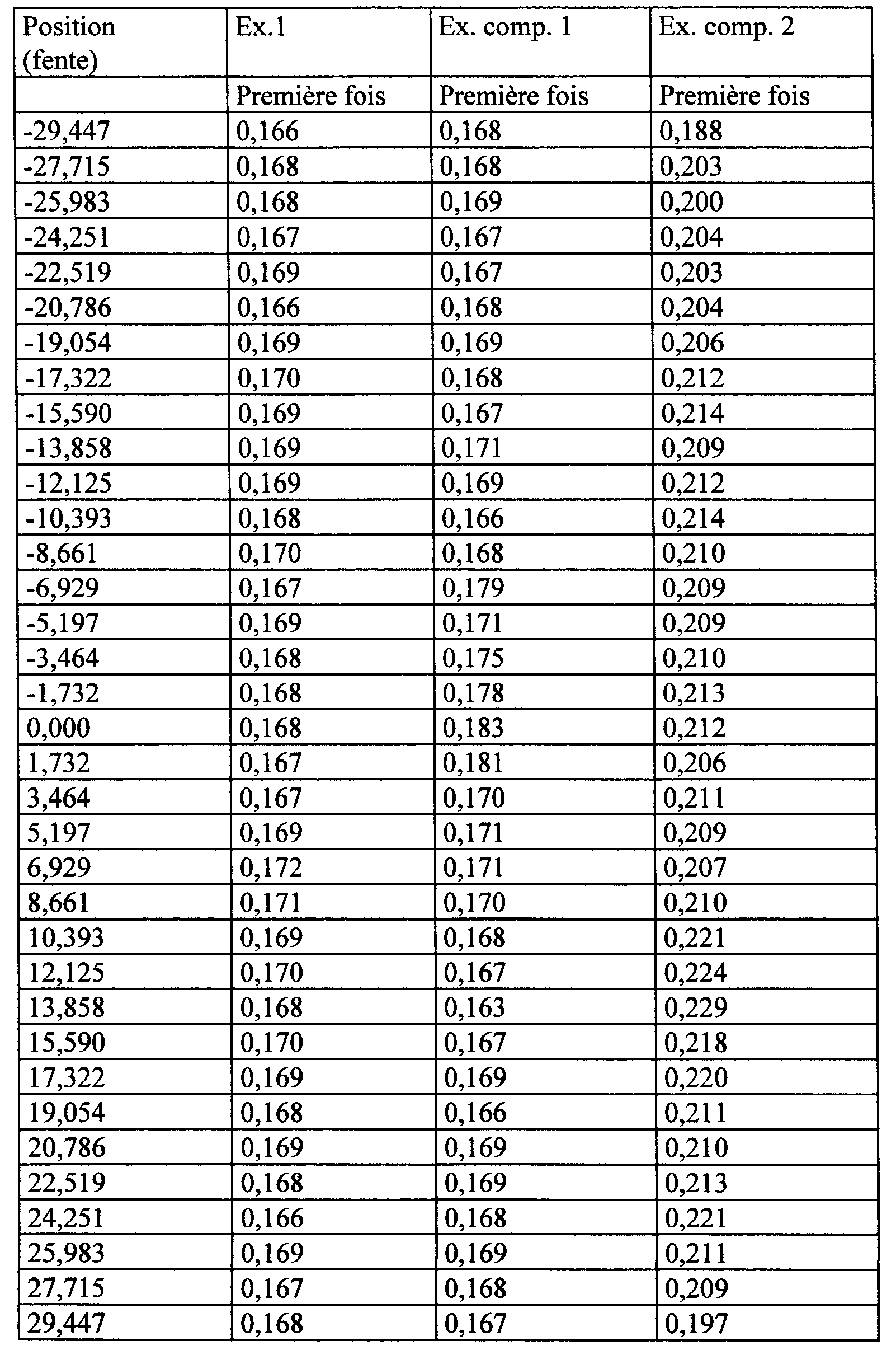
Comme l'illustrent le tableau 1, le tableau 2 et la Fig. 7, la filière utilisable pour la formation d'une structure alvéolée, produite dans l'exemple 1 présentait une petite largeur de fente, une fluctuation minime de la largeur et une précision d'usinage supérieure. La filière utilisable pour la formation d'une structure alvéolée produite dans l'exemple comparatif 1 a montré des fluctuations de largeur de la fente. La filière utilisable pour la formation d'une structure alvéolée, produite dans l'exemple comparatif 2, présentait une grande largeur de fente et d'importantes fluctuations de largeur.As shown in Table 1, Table 2 and FIG. 7, the die usable for the formation of a honeycomb structure, produced in Example 1 had a small slot width, a small fluctuation of the width and a higher machining accuracy. The die usable for forming a honeycomb structure produced in Comparative Example 1 showed slit width fluctuations. The useable die for forming a honeycomb structure, produced in Comparative Example 2, had a large slot width and large width fluctuations.
Applicabilité industrielleIndustrial applicability
Le présent procédé de production d'une filière utilisable pour la formation d'une structure alvéolée peut produire facilement et avec une grande précision une filière utilisable pour la formation d'une structure alvéolée présentant des alvéoles hexagonales.The present method of producing a die usable for the formation of a honeycomb structure can easily and very accurately produce a die usable for the formation of a honeycomb structure having hexagonal cells.
Claims (5)
Applications Claiming Priority (2)
| Application Number | Priority Date | Filing Date | Title |
|---|---|---|---|
| JP2004065517 | 2004-03-09 | ||
| JP2004065517A JP2005254345A (en) | 2004-03-09 | 2004-03-09 | Manufacturing method of mouthpiece for forming honeycomb structure |
Publications (1)
| Publication Number | Publication Date |
|---|---|
| BE1016832A3 true BE1016832A3 (en) | 2007-08-07 |
Family
ID=34918250
Family Applications (1)
| Application Number | Title | Priority Date | Filing Date |
|---|---|---|---|
| BE2005/0123A BE1016832A3 (en) | 2004-03-09 | 2005-03-08 | PROCESS FOR PRODUCING A USAGEABLE DIE FOR FORMING AN ALVEOLED STRUCTURE |
Country Status (3)
| Country | Link |
|---|---|
| US (1) | US7335848B2 (en) |
| JP (1) | JP2005254345A (en) |
| BE (1) | BE1016832A3 (en) |
Families Citing this family (13)
| Publication number | Priority date | Publication date | Assignee | Title |
|---|---|---|---|---|
| US7695128B2 (en) * | 2006-06-02 | 2010-04-13 | Eastman Kodak Company | Producing an ink jet image having high density and gray scale |
| JP2010522642A (en) | 2006-12-22 | 2010-07-08 | コーニング インコーポレイテッド | Step-down plunge electric discharge machining |
| JP5263655B2 (en) * | 2008-03-28 | 2013-08-14 | 日立金属株式会社 | Processing device and processing method for mold for forming ceramic honeycomb structure |
| US20110053757A1 (en) * | 2009-08-28 | 2011-03-03 | Stephen John Caffery | Methods for Making Aluminum Titanate Bodies and Minimizing Shrinkage Variability Thereof |
| US8263895B2 (en) * | 2009-08-28 | 2012-09-11 | Corning Incorporated | Electro-discharge electrode and method of use |
| JP5140106B2 (en) | 2010-03-23 | 2013-02-06 | 日本碍子株式会社 | Method for manufacturing die for forming honeycomb structure |
| JP5097234B2 (en) * | 2010-03-23 | 2012-12-12 | 日本碍子株式会社 | Method for manufacturing die for forming honeycomb structure |
| JP2012125882A (en) | 2010-12-15 | 2012-07-05 | Ngk Insulators Ltd | Electrode for mouthpiece for forming honeycomb structure |
| JP2012125883A (en) | 2010-12-15 | 2012-07-05 | Ngk Insulators Ltd | Manufacturing method of electrode for honeycomb structure forming die |
| JP5369085B2 (en) | 2010-12-15 | 2013-12-18 | 日本碍子株式会社 | Method for producing electrode for honeycomb structure forming die |
| US8611088B2 (en) * | 2011-11-16 | 2013-12-17 | Cooper Technologies Company | Mechanical heat pump for an electrical housing |
| JP5937762B2 (en) * | 2014-03-28 | 2016-06-22 | 日本碍子株式会社 | Electrode machining electrode and method for manufacturing honeycomb structure forming die |
| CN107206518B (en) | 2014-11-26 | 2019-05-14 | 康宁股份有限公司 | For manufacturing the device and method of extrusion die |
Citations (3)
| Publication number | Priority date | Publication date | Assignee | Title |
|---|---|---|---|---|
| JPS6328520A (en) * | 1986-07-16 | 1988-02-06 | Ngk Insulators Ltd | Manufacture of electric discharge machining electrode for forming honeycomb die |
| EP0759347A1 (en) * | 1995-08-21 | 1997-02-26 | Ngk Insulators, Ltd. | Method of manufacturing extrusion die for extruding honeycomb structural body |
| JP2002273626A (en) * | 2001-03-19 | 2002-09-25 | Denso Corp | Manufacturing method of die for forming honeycomb structure |
Family Cites Families (12)
| Publication number | Priority date | Publication date | Assignee | Title |
|---|---|---|---|---|
| US3699303A (en) * | 1970-10-15 | 1972-10-17 | Cincinnati Milacron Inc | Edm process a method and apparatus for controlling the flow rate of dielectric as a function of gap impedance |
| US4902216A (en) * | 1987-09-08 | 1990-02-20 | Corning Incorporated | Extrusion die for protrusion and/or high cell density ceramic honeycomb structures |
| JPH0230425A (en) * | 1988-07-20 | 1990-01-31 | Mitsubishi Electric Corp | Electric discharge machining device |
| JP3388650B2 (en) * | 1995-01-10 | 2003-03-24 | 株式会社神戸製鋼所 | EDM method |
| US6290837B1 (en) * | 1997-06-09 | 2001-09-18 | Denso Corporation | Method for machining slots in molding die |
| JP2000000723A (en) * | 1998-04-15 | 2000-01-07 | Denso Corp | Electric discharge machining method and electric discharge machining device |
| JP3402206B2 (en) | 1998-07-14 | 2003-05-06 | 株式会社デンソー | Method for manufacturing mold for forming honeycomb structure |
| US6448530B1 (en) | 1998-05-11 | 2002-09-10 | Denso Corporation | Metal mold for molding a honeycomb structure and method of producing the same |
| JP3478730B2 (en) | 1998-07-16 | 2003-12-15 | 日本碍子株式会社 | Wire electric discharge machine, wire electric discharge method, and extrusion mold |
| JP2001225312A (en) * | 1999-12-10 | 2001-08-21 | Ngk Insulators Ltd | Method for manufacturing mouth piece |
| JP4332289B2 (en) * | 2000-08-28 | 2009-09-16 | 株式会社放電精密加工研究所 | Method for manufacturing hexagonal cell honeycomb extrusion mold |
| JP3820894B2 (en) | 2001-02-13 | 2006-09-13 | 株式会社デンソー | Manufacturing method of mold for forming honeycomb structure |
-
2004
- 2004-03-09 JP JP2004065517A patent/JP2005254345A/en active Pending
-
2005
- 2005-03-07 US US11/072,960 patent/US7335848B2/en not_active Expired - Fee Related
- 2005-03-08 BE BE2005/0123A patent/BE1016832A3/en not_active IP Right Cessation
Patent Citations (3)
| Publication number | Priority date | Publication date | Assignee | Title |
|---|---|---|---|---|
| JPS6328520A (en) * | 1986-07-16 | 1988-02-06 | Ngk Insulators Ltd | Manufacture of electric discharge machining electrode for forming honeycomb die |
| EP0759347A1 (en) * | 1995-08-21 | 1997-02-26 | Ngk Insulators, Ltd. | Method of manufacturing extrusion die for extruding honeycomb structural body |
| JP2002273626A (en) * | 2001-03-19 | 2002-09-25 | Denso Corp | Manufacturing method of die for forming honeycomb structure |
Also Published As
| Publication number | Publication date |
|---|---|
| US20050198822A1 (en) | 2005-09-15 |
| US7335848B2 (en) | 2008-02-26 |
| JP2005254345A (en) | 2005-09-22 |
Similar Documents
| Publication | Publication Date | Title |
|---|---|---|
| BE1016832A3 (en) | PROCESS FOR PRODUCING A USAGEABLE DIE FOR FORMING AN ALVEOLED STRUCTURE | |
| BE1017633A5 (en) | PROCESS FOR PRODUCING A HONEYCOMB STRUCTURE FORMING DIE AND DIE THUS OBTAINED | |
| BE1005015A3 (en) | Method and apparatus for forming an article having multiple densities and / or cells geometries. | |
| BE1014387A3 (en) | Metal mold for casting structure honeycomb and manufacturing method thereof. | |
| FR2467067A1 (en) | DEVICE FOR MANUFACTURING ALVEOLAR STRUCTURE BY EXTRUSION OF A CERAMIC MATERIAL, AND METHOD OF OBTAINING SAID DEVICE | |
| FR2548090A1 (en) | PROCESS FOR COLD EXTRUSION FORMATION OF A CUPPER OF SPARK PLUG | |
| JP2010234515A (en) | Method for manufacturing metal cap for molding honeycomb structure | |
| US8914966B2 (en) | Die for molding honeycomb structure, and its production method | |
| BE1009797A5 (en) | Extrusion device body in its structure of bees and method for producing a body structure honeycomb using the device extrusion. | |
| WO2023105137A2 (en) | Tool-electrode capable of producing sealing slots in a cmc material by means of edm | |
| EP4034372A1 (en) | Additive manufacturing method | |
| JP2002273626A (en) | Manufacturing method of die for forming honeycomb structure | |
| FR3050391A1 (en) | ADDITIVE MANUFACTURING METHOD AND PIECE OBTAINED BY SUCH A METHOD | |
| FR2572665A1 (en) | Electrode tool for cutting by electroerosion, method of cutting by electroerosion by means of the said electrode tool and parts cut in accordance with the said method | |
| FR2692185A1 (en) | Process for manufacturing a metal part by oxycutting, oxycutting device and metal part obtained. | |
| FR2616695A1 (en) | METHOD FOR MANUFACTURING A CUTTING TOOL BY ELECTRO-EROSION, ELECTRODE AND CORRESPONDING TOOL | |
| EP4031311A1 (en) | Method for separating a part blank from a support by fluid expansion in the additively manufactured support | |
| FR3102706A1 (en) | Separation of a blank part manufactured by additive manufacturing from a base by an ejector | |
| JP2009012286A (en) | Method of manufacturing mold having groove part, and method of manufacturing mold having molding groove part for molding honeycomb structure | |
| JPH1177189A (en) | Manufacture of die | |
| EP3342304A1 (en) | Method for manufacturing a bracelet strand | |
| JPH0375323B2 (en) | ||
| Masaki et al. | Repetitive pattern transfer process of micro EDM | |
| FR2494155A1 (en) | ELECTRO-EROSION MACHINING ELECTRODE AND METHOD FOR CARRYING OUT THE SAME | |
| FR2582981A1 (en) | Dies for manufacturing extruded parts including a plurality of channels and processes for manufacturing these dies |
Legal Events
| Date | Code | Title | Description |
|---|---|---|---|
| RE | Patent lapsed |
Effective date: 20120331 |