RU2630119C2 - Method and device for heating press moulds, in particular, for pressure moulding - Google Patents
Method and device for heating press moulds, in particular, for pressure moulding Download PDFInfo
- Publication number
- RU2630119C2 RU2630119C2 RU2015101238A RU2015101238A RU2630119C2 RU 2630119 C2 RU2630119 C2 RU 2630119C2 RU 2015101238 A RU2015101238 A RU 2015101238A RU 2015101238 A RU2015101238 A RU 2015101238A RU 2630119 C2 RU2630119 C2 RU 2630119C2
- Authority
- RU
- Russia
- Prior art keywords
- core
- mold
- molding surface
- heating
- molding
- Prior art date
Links
Images
Classifications
-
- B—PERFORMING OPERATIONS; TRANSPORTING
- B29—WORKING OF PLASTICS; WORKING OF SUBSTANCES IN A PLASTIC STATE IN GENERAL
- B29C—SHAPING OR JOINING OF PLASTICS; SHAPING OF MATERIAL IN A PLASTIC STATE, NOT OTHERWISE PROVIDED FOR; AFTER-TREATMENT OF THE SHAPED PRODUCTS, e.g. REPAIRING
- B29C33/00—Moulds or cores; Details thereof or accessories therefor
- B29C33/02—Moulds or cores; Details thereof or accessories therefor with incorporated heating or cooling means
- B29C33/08—Moulds or cores; Details thereof or accessories therefor with incorporated heating or cooling means for dielectric heating
-
- B—PERFORMING OPERATIONS; TRANSPORTING
- B29—WORKING OF PLASTICS; WORKING OF SUBSTANCES IN A PLASTIC STATE IN GENERAL
- B29C—SHAPING OR JOINING OF PLASTICS; SHAPING OF MATERIAL IN A PLASTIC STATE, NOT OTHERWISE PROVIDED FOR; AFTER-TREATMENT OF THE SHAPED PRODUCTS, e.g. REPAIRING
- B29C45/00—Injection moulding, i.e. forcing the required volume of moulding material through a nozzle into a closed mould; Apparatus therefor
- B29C45/17—Component parts, details or accessories; Auxiliary operations
- B29C45/72—Heating or cooling
- B29C45/73—Heating or cooling of the mould
-
- B—PERFORMING OPERATIONS; TRANSPORTING
- B22—CASTING; POWDER METALLURGY
- B22D—CASTING OF METALS; CASTING OF OTHER SUBSTANCES BY THE SAME PROCESSES OR DEVICES
- B22D17/00—Pressure die casting or injection die casting, i.e. casting in which the metal is forced into a mould under high pressure
- B22D17/20—Accessories: Details
- B22D17/22—Dies; Die plates; Die supports; Cooling equipment for dies; Accessories for loosening and ejecting castings from dies
- B22D17/2218—Cooling or heating equipment for dies
-
- B—PERFORMING OPERATIONS; TRANSPORTING
- B29—WORKING OF PLASTICS; WORKING OF SUBSTANCES IN A PLASTIC STATE IN GENERAL
- B29C—SHAPING OR JOINING OF PLASTICS; SHAPING OF MATERIAL IN A PLASTIC STATE, NOT OTHERWISE PROVIDED FOR; AFTER-TREATMENT OF THE SHAPED PRODUCTS, e.g. REPAIRING
- B29C33/00—Moulds or cores; Details thereof or accessories therefor
- B29C33/02—Moulds or cores; Details thereof or accessories therefor with incorporated heating or cooling means
- B29C33/06—Moulds or cores; Details thereof or accessories therefor with incorporated heating or cooling means using radiation, e.g. electro-magnetic waves, induction heating
-
- B—PERFORMING OPERATIONS; TRANSPORTING
- B29—WORKING OF PLASTICS; WORKING OF SUBSTANCES IN A PLASTIC STATE IN GENERAL
- B29C—SHAPING OR JOINING OF PLASTICS; SHAPING OF MATERIAL IN A PLASTIC STATE, NOT OTHERWISE PROVIDED FOR; AFTER-TREATMENT OF THE SHAPED PRODUCTS, e.g. REPAIRING
- B29C35/00—Heating, cooling or curing, e.g. crosslinking or vulcanising; Apparatus therefor
- B29C35/02—Heating or curing, e.g. crosslinking or vulcanizing during moulding, e.g. in a mould
- B29C35/08—Heating or curing, e.g. crosslinking or vulcanizing during moulding, e.g. in a mould by wave energy or particle radiation
- B29C35/0805—Heating or curing, e.g. crosslinking or vulcanizing during moulding, e.g. in a mould by wave energy or particle radiation using electromagnetic radiation
-
- B—PERFORMING OPERATIONS; TRANSPORTING
- B29—WORKING OF PLASTICS; WORKING OF SUBSTANCES IN A PLASTIC STATE IN GENERAL
- B29C—SHAPING OR JOINING OF PLASTICS; SHAPING OF MATERIAL IN A PLASTIC STATE, NOT OTHERWISE PROVIDED FOR; AFTER-TREATMENT OF THE SHAPED PRODUCTS, e.g. REPAIRING
- B29C45/00—Injection moulding, i.e. forcing the required volume of moulding material through a nozzle into a closed mould; Apparatus therefor
- B29C45/17—Component parts, details or accessories; Auxiliary operations
- B29C45/26—Moulds
- B29C45/263—Moulds with mould wall parts provided with fine grooves or impressions, e.g. for record discs
- B29C45/2642—Heating or cooling means therefor
-
- B—PERFORMING OPERATIONS; TRANSPORTING
- B29—WORKING OF PLASTICS; WORKING OF SUBSTANCES IN A PLASTIC STATE IN GENERAL
- B29C—SHAPING OR JOINING OF PLASTICS; SHAPING OF MATERIAL IN A PLASTIC STATE, NOT OTHERWISE PROVIDED FOR; AFTER-TREATMENT OF THE SHAPED PRODUCTS, e.g. REPAIRING
- B29C45/00—Injection moulding, i.e. forcing the required volume of moulding material through a nozzle into a closed mould; Apparatus therefor
- B29C45/17—Component parts, details or accessories; Auxiliary operations
- B29C45/72—Heating or cooling
- B29C45/73—Heating or cooling of the mould
- B29C45/7331—Heat transfer elements, e.g. heat pipes
-
- B—PERFORMING OPERATIONS; TRANSPORTING
- B29—WORKING OF PLASTICS; WORKING OF SUBSTANCES IN A PLASTIC STATE IN GENERAL
- B29C—SHAPING OR JOINING OF PLASTICS; SHAPING OF MATERIAL IN A PLASTIC STATE, NOT OTHERWISE PROVIDED FOR; AFTER-TREATMENT OF THE SHAPED PRODUCTS, e.g. REPAIRING
- B29C35/00—Heating, cooling or curing, e.g. crosslinking or vulcanising; Apparatus therefor
- B29C35/02—Heating or curing, e.g. crosslinking or vulcanizing during moulding, e.g. in a mould
- B29C35/08—Heating or curing, e.g. crosslinking or vulcanizing during moulding, e.g. in a mould by wave energy or particle radiation
- B29C35/0805—Heating or curing, e.g. crosslinking or vulcanizing during moulding, e.g. in a mould by wave energy or particle radiation using electromagnetic radiation
- B29C2035/0811—Heating or curing, e.g. crosslinking or vulcanizing during moulding, e.g. in a mould by wave energy or particle radiation using electromagnetic radiation using induction
-
- B—PERFORMING OPERATIONS; TRANSPORTING
- B29—WORKING OF PLASTICS; WORKING OF SUBSTANCES IN A PLASTIC STATE IN GENERAL
- B29C—SHAPING OR JOINING OF PLASTICS; SHAPING OF MATERIAL IN A PLASTIC STATE, NOT OTHERWISE PROVIDED FOR; AFTER-TREATMENT OF THE SHAPED PRODUCTS, e.g. REPAIRING
- B29C45/00—Injection moulding, i.e. forcing the required volume of moulding material through a nozzle into a closed mould; Apparatus therefor
- B29C45/14—Injection moulding, i.e. forcing the required volume of moulding material through a nozzle into a closed mould; Apparatus therefor incorporating preformed parts or layers, e.g. injection moulding around inserts or for coating articles
- B29C2045/1486—Details, accessories and auxiliary operations
- B29C2045/14868—Pretreatment of the insert, e.g. etching, cleaning
- B29C2045/14877—Pretreatment of the insert, e.g. etching, cleaning preheating or precooling the insert for non-deforming purposes
-
- B—PERFORMING OPERATIONS; TRANSPORTING
- B29—WORKING OF PLASTICS; WORKING OF SUBSTANCES IN A PLASTIC STATE IN GENERAL
- B29C—SHAPING OR JOINING OF PLASTICS; SHAPING OF MATERIAL IN A PLASTIC STATE, NOT OTHERWISE PROVIDED FOR; AFTER-TREATMENT OF THE SHAPED PRODUCTS, e.g. REPAIRING
- B29C45/00—Injection moulding, i.e. forcing the required volume of moulding material through a nozzle into a closed mould; Apparatus therefor
- B29C45/17—Component parts, details or accessories; Auxiliary operations
- B29C45/72—Heating or cooling
- B29C45/73—Heating or cooling of the mould
- B29C2045/735—Heating or cooling of the mould heating a mould part and cooling another mould part during moulding
-
- B—PERFORMING OPERATIONS; TRANSPORTING
- B29—WORKING OF PLASTICS; WORKING OF SUBSTANCES IN A PLASTIC STATE IN GENERAL
- B29C—SHAPING OR JOINING OF PLASTICS; SHAPING OF MATERIAL IN A PLASTIC STATE, NOT OTHERWISE PROVIDED FOR; AFTER-TREATMENT OF THE SHAPED PRODUCTS, e.g. REPAIRING
- B29C2791/00—Shaping characteristics in general
- B29C2791/004—Shaping under special conditions
- B29C2791/005—Using a particular environment, e.g. sterile fluids other than air
-
- B—PERFORMING OPERATIONS; TRANSPORTING
- B29—WORKING OF PLASTICS; WORKING OF SUBSTANCES IN A PLASTIC STATE IN GENERAL
- B29C—SHAPING OR JOINING OF PLASTICS; SHAPING OF MATERIAL IN A PLASTIC STATE, NOT OTHERWISE PROVIDED FOR; AFTER-TREATMENT OF THE SHAPED PRODUCTS, e.g. REPAIRING
- B29C45/00—Injection moulding, i.e. forcing the required volume of moulding material through a nozzle into a closed mould; Apparatus therefor
- B29C45/17—Component parts, details or accessories; Auxiliary operations
- B29C45/40—Removing or ejecting moulded articles
- B29C45/42—Removing or ejecting moulded articles using means movable from outside the mould between mould parts, e.g. robots
Landscapes
- Mechanical Engineering (AREA)
- Engineering & Computer Science (AREA)
- Health & Medical Sciences (AREA)
- Manufacturing & Machinery (AREA)
- Physics & Mathematics (AREA)
- Toxicology (AREA)
- Thermal Sciences (AREA)
- Electromagnetism (AREA)
- Oral & Maxillofacial Surgery (AREA)
- Moulds For Moulding Plastics Or The Like (AREA)
- Injection Moulding Of Plastics Or The Like (AREA)
- General Induction Heating (AREA)
- Molds, Cores, And Manufacturing Methods Thereof (AREA)
Abstract
Description
Изобретение относится к способу и к устройству для подогрева пресс-формы. В частности, но не исключительно, изобретение находит свое применение для подогрева пресс-формы, используемой в процессе литья под давлением пластического материала или металла в жидком или пастообразном состоянии и, в частности, для литья под давлением материала, содержащего усиления, например, в виде коротких волокон.The invention relates to a method and a device for heating a mold. In particular, but not exclusively, the invention finds its application for heating a mold used in the injection molding process of a plastic material or metal in a liquid or pasty state and, in particular, for injection molding of a material containing reinforcements, for example, in the form short fibers.
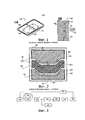
На фиг. 1А, относящейся к известному техническому решению, схематично показана тонкая деталь 100, изготавливаемая серийно посредством литья под давлением. Например, эта деталь является крышкой электронного прибора. Если она имеет большие размеры, например, если речь идет о крышке телевизора с большим экраном, указанную деталь выполняют из полимера, усиленного наполнителем в виде волокон или шариков. Как правило, такая деталь 100 содержит сторону 110, называемую внешней, являющуюся гладкой или имеющую отделочную текстуру, при этом указанная сторона остается видимой после соединения указанной детали с прибором. Согласно частному варианту выполнения, эта сторона содержит декоративный рисунок, получаемый во время литья под давлением пластического материала в пресс-форме после наложения декоративной пленки на внутреннюю сторону указанной пресс-формы. Деталь 100 содержит также сторону 120, называемую технической, которая содержит многочисленные рельефные элементы, такие как ребра 121, гнезда 122 под винты, пазы 123 и т.д. Показанную на фиг. 1В деталь 100 выполняют посредством горячего литья под давлением пластического материала, содержащего усиливающий наполнитель, в закрытой полости 122 пресс-формы 150. Эта пресс-форма содержит неподвижную часть 151 и подвижную часть 152. Нагнетаемый материал поступает в полость 153 через канал 161, выполненный в неподвижной части и соединенный с устройством нагнетания 160, например, шнеком. Для заполнения всей полости 153 и обеспечения однородного внешнего вида, в частности, внешней стороны детали, пресс-форму 150 необходимо перед нагнетанием подогреть, чтобы получить однородную температуру поверхности полости, входящей в контакт с нагнетаемым полимером. В случае процесса серийного производства желательно максимально сокращать время подогрева и охлаждения пресс-формы. Согласно известному решению, формовочные поверхности пресс-формы, в частности, формовочную поверхность, находящуюся на неподвижной части указанной пресс-формы, нагревают, например, при помощи устройств нагрева, расположенных в пазах или отверстиях под указанными формовочными поверхностями. Эти элементы являются сложными в изготовлении на пресс-формах большого размера и являются причиной механического ослабления формовочных поверхностей. Поскольку нагрев происходит за счет теплопроводности внутри самих частей пресс-формы, то нагревается большой объем материала, что приводит к чрезмерному расходу энергии и затрудняет достижение высокой скорости нагрева.In FIG. 1A, related to a known technical solution, a
Для повышения скорости нагрева, согласно известному решению, поверхности пресс-формы с двух сторон от полости можно нагревать путем индукционного нагрева.To increase the heating rate, according to a known solution, the surface of the mold on both sides of the cavity can be heated by induction heating.
Такой способ подогрева, представленный на фиг. 2, описан в документе WO 2010046582. Согласно этому известному способу, обе части 151, 152 пресс-формы выполнены из электропроводящего и ферромагнитного материала, например, из стали, содержащей в основном ферритную фазу. Предпочтительно каждую из этих двух частей вставляют в каркас 251, 252, выполненный из немагнитного проводящего материала, такого как медь Cu, за исключением так называемых формовочных поверхностей 261, 262, ограничивающих полость пресс-формы. Индукционный контур 210, состоящий из одного или нескольких витков, охватывает обе части 151, 152 пресс-формы. Между двумя частями 151, 152 пресс-формы располагают промежуточную деталь 270, называемую сердечником, выполненную из электропроводящего материала. Этот сердечник электрически изолирован от обеих частей 151, 152 пресс-формы. Расположенный таким образом, сердечник 270 содержит поверхности 271, 272, отделенные небольшим расстоянием от формовочных поверхностей 261, 262 двух частей пресс-формы, ограничивая таким образом вместе с указанными формовочными поверхностями два изолирующих зазора e1, е2. Когда через индукционный контур пропускают переменный ток высокой частоты, на находящихся друг против друга сторонах 261, 271, 262, 272 сердечника и формовочных поверхностей по обе стороны от этих зазоров циркулируют наведенные токи, способствуя быстрому нагреву ферромагнитных формовочных поверхностей 261, 262. Повышенная магнитная проницаемость ферромагнитной стали способствует тому, что наведенные токи проходят только по поверхности на незначительной глубине от указанных формовочных поверхностей. Таким образом, этот способ подогрева позволяет быстро нагревать формовочные поверхности за счет индукции, концентрируя нагрев на этих поверхностях, когда между ними вставлен сердечник 270, при этом пресс-форма открыта. Для осуществления литья под давлением сердечник извлекают, пресс-форму 150 закрывают путем сближения двух частей 151, 152, после чего в формовочную полость чрез один или несколько каналов (не показаны) нагнетают материал в жидком или пастообразном состоянии. Температуру подогрева контролируют путем регулирования электрической мощности, подаваемой в индукционный контур, и времени нагрева. Эту температуру выбирают достаточной, что обеспечивать легкое перетекание нагнетаемого материала по всей полости, после чего тепло указанного материала удаляется через массу пресс-формы, которая предпочтительно содержит контур охлаждения, например, посредством циркуляции текучей среды в охлаждающих каналах 281, 282, выполненных в каждой из частей пресс-формы и проходящих через них в непосредственной близости от формовочных поверхностей. Таким образом, возможность нагревать только формовочные поверхности на небольшой глубине дает выигрыш в производительности как при нагреве, так и при охлаждении.Such a heating method as shown in FIG. 2, is described in document WO 2010046582. According to this known method, both
Этот известный способ является эффективным для подогрева формовочной поверхности внешней стороны детали, но он не подходит для подогрева формовочной поверхности технической стороны. Действительно, многочисленные рельефные элементы и технические приспособления, которые содержит эта сторона, такие как выдвижные блоки или кулисы, не позволяют легко получать постоянный зазор между сердечником и соответствующей формовочной поверхностью, к тому же эти неровности формы нарушают циркуляцию наведенных токов, приводя к локальным перегревам и даже к явлениям электрической дуги.This known method is effective for heating the molding surface of the outer side of the part, but it is not suitable for heating the molding surface of the technical side. Indeed, the numerous relief elements and technical devices that this side contains, such as sliding blocks or wings, do not make it easy to obtain a constant gap between the core and the corresponding molding surface, moreover, these irregularities disrupt the circulation of induced currents, leading to local overheating and even to the phenomena of an electric arc.
В документе АТ 504784 описаны способ и устройство подогрева пресс-формы, адаптированное для процесса литья под давлением пластического материала, содержащее устройство подогрева тепловым излучением одной из формовочных поверхностей этой пресс-формы. Для достижения быстрого подогрева указанной формовочной поверхности эта формовочная поверхность представляет собой сторону тонкой детали, отстоящей от корпуса пресс-форм, когда указанная пресс-форма находится в открытом положении. Таким образом, уменьшается объем материала, нагреваемый излучением. Однако этот вариант осуществления является сложным и не подходит для формовочной поверхности, соответствующей технической стороне детали.The document AT 504784 describes a method and device for heating a mold adapted for the injection molding process of a plastic material, comprising a device for heating by thermal radiation of one of the molding surfaces of this mold. In order to achieve rapid heating of said molding surface, this molding surface is the side of a thin part spaced apart from the mold body when said mold is in the open position. Thus, the volume of material heated by radiation is reduced. However, this embodiment is complex and not suitable for the molding surface corresponding to the technical side of the part.
В документе DE 102008060496 описаны способ и устройство подогрева, при которых часть пресс-формы, содержащую формовочную поверхность, перемещают наружу указанной пресс-формы для подогрева.DE 102008060496 describes a heating method and device in which a part of a mold containing a molding surface is moved outside of said heating mold.
Задача изобретения состоит в устранении вышеуказанных недостатков, присущих известным техническим решениям.The objective of the invention is to eliminate the above disadvantages inherent in known technical solutions.
Поставленная задача решена в способе подогрева первой формовочной поверхности пресс-формы, при этом пресс-форма имеет открытое положение и закрытое положение и ограничивает в этом закрытом положении закрытую полость между первой подогреваемой формовочной поверхностью и второй формовочной поверхностью, при этом указанный способ содержит следующие этапы, на которых:The problem is solved in the method of heating the first molding surface of the mold, the mold has an open position and a closed position and limits the closed cavity in this closed position between the first heated molding surface and the second molding surface, wherein the method comprises the following steps, where:
a. деталь, называемую сердечником, нагревают за счет индукции снаружи пресс-формы, устанавливая указанную деталь внутри витка, через который пропускают переменный ток;a. the part, called the core, is heated by induction outside the mold, installing the specified part inside the coil through which alternating current is passed;
b. указанный сердечник устанавливают между формовочными поверхностями указанной пресс-формы в открытом положении;b. the specified core is installed between the molding surfaces of the specified mold in the open position;
c. осуществляют подогрев первой формовочной поверхности за счет теплопередачи между указанным сердечником и указанной формовочной поверхностью;c. carry out the heating of the first molding surface due to heat transfer between the specified core and the specified molding surface;
d. извлекают сердечник и закрывают пресс-форму.d. remove the core and close the mold.
Таким образом, заявленный способ позволяет нагревать сердечник снаружи пресс-формы и концентрировать нагрев на формовочной поверхности, избегая трудностей, связанных с формой указанной формовочной поверхности, которая, согласно этому способу, нагревается за счет теплопередачи. Поскольку индукционный нагрев сердечника отделен от формовочной зоны, указанная формовочная зона оказывается менее загроможденной, и ее легче вводить в литейный пресс по сравнению с известными техническими решениями.Thus, the claimed method allows you to heat the core outside the mold and concentrate the heat on the molding surface, avoiding the difficulties associated with the shape of the specified molding surface, which, according to this method, is heated by heat transfer. Since the induction heating of the core is separated from the molding zone, this molding zone is less cluttered, and it is easier to introduce into the foundry press in comparison with the known technical solutions.
Изобретение можно выполнять в соответствии с описанными ниже вариантами осуществления, которые следует рассматривать индивидуально или в любой технически допустимой комбинации.The invention can be carried out in accordance with the following embodiments, which should be considered individually or in any technically feasible combination.
Согласно частному варианту осуществления, этап с) осуществляют при помощи теплопередачи, в основном происходящей за счет теплопроводности. Этот вариант осуществления обеспечивает быструю теплопередачу и нагрев сердечника при меньшей температуре, но требует контакта между формовочной поверхностью и сердечником.According to a particular embodiment, step c) is carried out using heat transfer, mainly due to heat conduction. This embodiment provides fast heat transfer and heating of the core at a lower temperature, but requires contact between the molding surface and the core.
Согласно другому варианту осуществления, этап а) включает в себя нагрев сердечника до температуры, составляющей от 700°С до 1200°С, и этап с) осуществляют при помощи теплопередачи в основном за счет излучения. Этот вариант осуществления больше адаптирован для нагрева сложной формовочной поверхности, содержащей многочисленные рельефные элементы. Применение индукционного нагрева сердечника снаружи пресс-формы позволяет нагревать его до высокой температуры для обеспечения быстрого и бесконтактного подогрева формовочной поверхности.According to another embodiment, step a) includes heating the core to a temperature of 700 ° C to 1200 ° C, and step c) is carried out using heat transfer mainly due to radiation. This embodiment is more adapted to heat a complex molding surface containing numerous embossed elements. The use of induction heating of the core outside the mold allows it to be heated to a high temperature to ensure quick and non-contact heating of the molding surface.
Предпочтительно этап а) осуществляют в атмосфере инертного газа. Таким образом, поверхности сердечника оказываются защищенными от окисления при высокой температуре во время фазы нагрева, что повышает срок службы этого сердечника.Preferably, step a) is carried out in an inert gas atmosphere. Thus, the core surfaces are protected from oxidation at high temperature during the heating phase, which increases the life of this core.
Предпочтительно этап а) осуществляют, помещая сердечник между двумя электропроводящими тепловыми экранами, электрически изолированными друг от друга и от сердечника, при этом весь комплекс располагают внутри витка. Таким образом, сердечник нагревается быстрее, и пресс-форма и окружающие ее технические элементы защищены от теплового излучения сердечника, нагреваемого до высокой температуры во время фазы нагрева этого сердечника.Preferably, step a) is carried out by placing a core between two electrically conductive heat shields that are electrically isolated from each other and from the core, with the entire complex located inside the coil. Thus, the core heats up faster, and the mold and the surrounding technical elements are protected from the thermal radiation of the core being heated to high temperature during the heating phase of this core.
Предпочтительно пресс-форма содержит канал для циркуляции текучей среды-теплоносителя, проходящий под первой формовочной поверхностью, и, согласно этому варианту осуществления, заявленный способ перед этапом с) содержит этап, на котором:Preferably, the mold comprises a channel for the circulation of the heat-transfer fluid passing under the first molding surface, and according to this embodiment, the inventive method before step c) comprises a step in which:
e. указанный канал продувают для удаления из него любой текучей среды.e. the specified channel is purged to remove any fluid from it.
Таким образом, продутый охлаждающий канал выполняет роль теплоизоляционного барьера между формовочной поверхностью и остальной частью пресс-формы.Thus, the blown cooling channel acts as a heat-insulating barrier between the molding surface and the rest of the mold.
Предпочтительно вторую формовочную поверхность тоже нагревают за счет теплопередачи во время этапа с). Таким образом, подогрев обеих формовочных поверхностей способствует однородному потоку разливаемого материала между формовочными поверхностями и позволяет избегать остаточных напряжений в детали, изготавливаемой при помощи заявленного способа.Preferably, the second molding surface is also heated by heat transfer during step c). Thus, the heating of both molding surfaces contributes to a uniform flow of the material to be poured between the molding surfaces and avoids residual stresses in the part made using the claimed method.
Согласно предпочтительному варианту осуществления заявленного способа, он содержат перед этапом d) этап, на котором:According to a preferred embodiment of the inventive method, it comprises, before step d) a step in which:
f. за счет индукции подогревают вторую формовочную поверхность, ограничивающую закрытую полость пресс-формы, помещая напротив указанной поверхности электропроводящую промежуточную деталь, электрически изолированную от указанной формовочной поверхности и образующую зазор с этой формовочной поверхностью, при этом соответствующую часть пресс-формы и указанную промежуточную деталь помещают в виток, через который пропускают переменный ток.f. by induction, the second molding surface bounding the closed cavity of the mold is heated, placing an electrically conductive intermediate part opposite to the indicated surface, electrically isolated from the specified molding surface and forming a gap with this molding surface, while the corresponding part of the mold and the specified intermediate part are placed in a loop through which alternating current is passed.
Этот вариант осуществления заявленного способа требует, чтобы пресс-форма тоже была оснащена индукционным контуром. В частности, но не исключительно этот вариант осуществления адаптирован к случаю литья с использованием декоративной пленки, укладываемой на вторую формовочную поверхность, и позволяет осуществлять подогрев этой второй формовочной поверхности, избегая повреждения прожиганием указанной пленки.This embodiment of the inventive method requires that the mold also be equipped with an induction circuit. In particular, but not exclusively, this embodiment is adapted to the case of casting using a decorative film laid on a second molding surface, and allows this second molding surface to be heated, avoiding damage by burning said film.
Согласно частому варианту заявленного способа, промежуточная деталь является сердечником, и этап f) осуществляют одновременно с этапом с), когда средства обеспечивают электропроводимость между сердечником и первой формовочной поверхностью, подогреваемой за счет теплопередачи. Таким образом, в ходе одной и той же операции подогрева обе формовочные поверхности пресс-формы нагреваются до соответствующей температуры подогрева, при этом первая формовочная поверхность нагревается только за счет теплопередачи, а вторая формовочная поверхность - в основном за счет индукции.According to a frequent variant of the claimed method, the intermediate part is a core, and step f) is carried out simultaneously with step c), when the means provide electrical conductivity between the core and the first molding surface, which is heated by heat transfer. Thus, during the same heating operation, both molding surfaces of the mold are heated to the corresponding heating temperature, while the first molding surface is heated only by heat transfer, and the second molding surface is mainly due to induction.
Предпочтительно в момент осуществления этапа f) вторую формовочную поверхность покрывают пластической декоративной пленкой, и после этапа d) способ содержит этап, на котором:Preferably, at the time of step f), the second molding surface is covered with a plastic decorative film, and after step d), the method comprises the step of:
g. в закрытую полость пресс-формы нагнетают расплавленный пластический материал.g. molten plastic material is injected into the closed cavity of the mold.
Объектом изобретения является также устройство для осуществления заявленного способа, предназначенное для подогрева пресс-формы, имеющей открытое положение и закрытое положение и ограничивающей в этом закрытом положении закрытую полость между первой формовочной поверхностью и второй формовочной поверхностью, при этом указанное устройство содержит:The object of the invention is also a device for implementing the inventive method, designed to heat a mold having an open position and a closed position and limiting in this closed position a closed cavity between the first molding surface and the second molding surface, wherein said device comprises:
- сердечник;- core;
- индукционные средства, отдельные от пресс-формы, для индукционного нагрева сердечника внутри витка в зоне нагрева;- induction means, separate from the mold, for induction heating of the core inside the coil in the heating zone;
- средства перемещения сердечника между зоной нагрева и пресс-формой.- means for moving the core between the heating zone and the mold.
Таким образом, осуществление заявленного способа является автоматизированным.Thus, the implementation of the claimed method is automated.
Согласно первому варианту осуществления заявленного устройства, сердечник представляет собой графитовый блок. Этот электропроводящий материал можно нагреть за счет индукции до высокой температуры, и он имеет коэффициент излучения, близкий к 1, способствующий теплопередаче за счет излучения.According to a first embodiment of the claimed device, the core is a graphite block. This electrically conductive material can be heated by induction to a high temperature, and it has an emissivity close to 1, which promotes heat transfer due to radiation.
Согласно второму варианту осуществления заявленного устройства, сердечник выполнен из ферромагнитного металлического материала, и его поверхность, находящаяся напротив первой формовочной поверхности, имеет покрытие, коэффициент излучения которого превышает 0,9. Этот вариант осуществления позволяет добиваться более быстрого нагрева сердечника, сохраняя при этом высокий коэффициент излучения его поверхности, чтобы способствовать теплопередаче за счет излучения.According to a second embodiment of the claimed device, the core is made of a ferromagnetic metal material, and its surface opposite the first molding surface has a coating whose emissivity exceeds 0.9. This embodiment makes it possible to achieve faster heating of the core, while maintaining a high emissivity of its surface in order to facilitate heat transfer due to radiation.
Предпочтительно покрытие сердечника согласно этому второму варианту заявленного устройства состоит из аморфного углерода. Это покрытие является исключительно стойким к окислению.Preferably, the core coating according to this second embodiment of the claimed device consists of amorphous carbon. This coating is extremely resistant to oxidation.
Предпочтительно сердечник является полым. Таким образом, масса указанного сердечника уменьшена, что ускоряет его нагрев и облегчает его перемещения.Preferably, the core is hollow. Thus, the mass of the specified core is reduced, which accelerates its heating and facilitates its movement.
Предпочтительно средства перемещения заявленного устройства представляют собой робот, при этом указанный робот дополнительно содержит средства для извлечения из пресс-формы детали, выполненной в полости пресс-формы. Таким образом, используют одно и то же устройство для извлечения детали из пресс-формы и для введения сердечника между частями пресс-формы, что позволяет уменьшить габаритные размеры устройства и повысить производительность формования, комбинируя задачи робота в ходе осуществления одной и той же кинематической операции.Preferably, the means of moving the claimed device is a robot, wherein said robot further comprises means for extracting from the mold a part made in the cavity of the mold. Thus, the same device is used to extract the part from the mold and to introduce the core between the parts of the mold, which allows to reduce the overall dimensions of the device and increase the productivity of molding, combining the tasks of the robot during the same kinematic operation.
Предпочтительно средства индукционного нагрева заявленного устройства содержат:Preferably, the induction heating means of the claimed device comprise:
- первый экран, выполненный из электропроводящего, но не являющегося ферромагнитным материала;- the first screen made of an electrically conductive, but non-ferromagnetic material;
- второй экран, выполненный из электропроводящего, но не являющегося ферромагнитным материала;- a second screen made of an electrically conductive but non-ferromagnetic material;
- средства для сдвигания и раздвигания двух экранов и средства для удержания сердечника между двумя экранами, когда они находятся в сдвинутом положении;- means for moving and sliding the two screens and means for holding the core between the two screens when they are in a shifted position;
- индуктор, содержащий виток, охватывающий оба экрана, при этом указанный виток состоит из двух полувитков, каждый из которых связан с одним из экранов и содержит соединители для обеспечения электрической непрерывности между двумя полувитками, когда оба экрана находятся в сдвинутом положении;- an inductor containing a coil covering both screens, wherein said coil consists of two half-coils, each of which is connected to one of the screens and contains connectors to ensure electrical continuity between the two half-coils when both screens are in a shifted position;
- средства для электрической изоляции сердечника от двух экранов и для создания зазора между сторонами сердечника напротив сторон экранов.- means for electrically isolating the core from two screens and for creating a gap between the sides of the core opposite the sides of the screens.
Таким образом, сердечник быстро нагревают за счет индукции, создавая два зазора и защищая двумя экранами окружающую его среду от излучения сердечника.Thus, the core is quickly heated by induction, creating two gaps and protecting the surrounding environment from the core radiation with two screens.
Предпочтительно экраны являются полыми. Таким образом, ими легче манипулировать, и устройство является более компактным.Preferably, the screens are hollow. Thus, they are easier to manipulate, and the device is more compact.
Предпочтительно экраны содержат внутренний контур охлаждения для циркуляции текучей среды-теплоносителя. Таким образом, устройство можно применять с соблюдением высоких ритмов производства без риска повреждения экранов, связанного с их перегревом при излучении сердечника.Preferably, the screens comprise an internal cooling circuit for circulating the heat transfer fluid. Thus, the device can be used in compliance with high production rhythms without the risk of damage to the screens associated with their overheating when the core is emitted.
Объектом изобретения является также устройство для литья под давлением материала в жидком или пастообразном состоянии в полости пресс-формы, содержащей две части, подвижные относительно друг друга и ограничивающие между собой закрытую полость, образованную между двумя формовочными поверхностями, при этом указанное устройство содержит устройство подогрева согласно любому из предыдущих вариантов осуществления.The object of the invention is also a device for injection molding material in a liquid or pasty state in the cavity of a mold containing two parts that are movable relative to each other and bound to each other by a closed cavity formed between two molding surfaces, said device comprising a heating device according to to any of the previous embodiments.
Предпочтительно формовочная поверхность, в основном нагреваемая за счет теплового излучения, содержит покрытие, коэффициент излучения которого превышает 0,9. Таким образом, улучшается теплопередача за счет излучения между этой формовочной поверхностью и сердечником.Preferably, the molding surface, mainly heated by thermal radiation, contains a coating whose emissivity exceeds 0.9. In this way, heat transfer is improved due to radiation between this molding surface and the core.
Далее следует описание предпочтительных, но неограничивающих вариантов осуществления изобретения со ссылками на фиг. 1-8, на которых:The following is a description of preferred, but non-limiting embodiments of the invention with reference to FIGS. 1-8, on which:
на фиг. 1 представлено известное решение, при этом на фиг. 1А показана деталь, полученная путем литья под давлением пластического материала и содержащая внешнюю сторону и техническую сторону, а на фиг. 1В показана пресс-форма для изготовления такой детали, виды в перспективе и в разрезе соответственно;in FIG. 1 shows a known solution, with FIG. 1A shows a part obtained by injection molding of a plastic material and containing an external side and a technical side, and in FIG. 1B shows a mold for manufacturing such a part, perspective and sectional views, respectively;
на фиг. 2 показан пример осуществления известного устройства индукционного подогрева формовочных поверхностей пресс-формы, вид в разрезе;in FIG. 2 shows an example implementation of a known device for induction heating of molding surfaces of a mold, sectional view;
на фиг. 3 представлена блок-схема примера осуществления заявленного способа;in FIG. 3 is a flowchart of an embodiment of the claimed method;
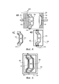
на фиг. 4, представлены: на фиг. 4А - пример осуществления заявленного устройства, на фиг. 4В - устройство нагрева, отделенное от сердечника, на фиг. 4С - вариант осуществления сердечника, содержащего подложку и покрытие с коэффициентом излучения, близким к 1, виды в разрезе;in FIG. 4 are presented: in FIG. 4A is an example embodiment of the claimed device, in FIG. 4B is a heating device separated from the core, in FIG. 4C is an embodiment of a core comprising a substrate and a coating with an emissivity close to 1, sectional views;
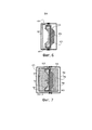
на фиг. 5 показан пример осуществления зоны индукционного нагрева сердечника, при этом указанная зона содержит два экрана, образующих зазоры с поверхностями сердечника, вид в разрезе;in FIG. 5 shows an example of the implementation of the induction heating zone of the core, while this zone contains two screens forming gaps with the surfaces of the core, a sectional view;
на фиг. 6 показан пример осуществления сердечника, включающего в себя соединение двух материалов, а также примера осуществления зоны нагрева сердечника, адаптированной для этого варианта осуществления, вид в разрезе;in FIG. 6 shows an example implementation of a core including a connection of two materials, as well as an example implementation of a core heating zone adapted for this embodiment, a sectional view;
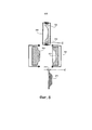
на фиг. 7 показан пример осуществления заявленного устройства с использованием сердечника, состоящего из двух соединенных между собой частей, как показано на фиг. 6, при этом одна формовочная поверхность нагревается за счет теплопередачи, а другая формовочная поверхность - за счет индукции, вид в разрезе;in FIG. 7 shows an example implementation of the claimed device using a core consisting of two interconnected parts, as shown in FIG. 6, while one molding surface is heated by heat transfer, and the other molding surface is due to induction, a sectional view;
на фиг. 8 показан пример осуществления заявленного устройства, содержащего сердечник из двух разделяемых частей, при этом одну часть нагревают за счет индукции перед ее соединением с другой частью указанного сердечника.in FIG. 8 shows an example implementation of the inventive device containing a core of two shared parts, while one part is heated by induction before connecting it to the other part of the specified core.
На фиг. 3 представлен пример осуществления заявленного способа подогрева в рамках процесса литья под давлением. На первом этапе 310, называемом этапом открывания, пресс-форму открывают. В ходе этапа 325 извлечения деталь извлекают из пресс-формы и удаляют. Параллельно во время этапа 320 введения сердечник вводят в нагретом состоянии между двумя открытыми частями пресс-формы. Части пресс-формы сдвигают, чтобы охватить ими сердечник, во время этапа 330 подогрева. Во время этого этапа подогрева, по меньшей мере, одна из формовочных поверхностей пресс-формы, которая входит в контакт со сердечником или находится вблизи него, нагревается посредством теплопередачи. Эта теплопередача происходит за счет теплопроводности, конвекции или излучения в зависимости от варианта осуществления устройства в соответствии с изобретением.In FIG. 3 presents an example implementation of the inventive heating method as part of the injection molding process. In a
Согласно второму варианту осуществления, способ содержит этап 335 индукционного нагрева одной из формовочных поверхностей, осуществляемый, когда сердечник вводят в пресс-форму.According to a second embodiment, the method comprises the
Таким образом, по меньшей мере, одну из формовочных поверхностей пресс-формы, предпочтительно формовочную поверхность для осуществления технической стороны нагревают посредством теплопередачи за счет теплопроводности, конвекции или излучения, а формовочную поверхность, соответствующую внешней стороне, нагревают посредством теплопередачи или за счет индукции.Thus, at least one of the molding surfaces of the mold, preferably the molding surface for the implementation of the technical side is heated by heat transfer due to heat conduction, convection or radiation, and the molding surface corresponding to the outside is heated by heat transfer or by induction.
Когда формовочные поверхности пресс-формы достигают соответствующей температуры, пресс-форму открывают и сердечник извлекают в ходе этапа 340 извлечения. Затем пресс-форму опять закрывают 350 под давлением, чтобы получить герметичную полость между формовочными поверхностями указанной пресс-формы. Материал для изготовления детали нагнетают в пресс-форму во время этапа 360 нагнетания, после которого следует этап охлаждения 370. После этого пресс-форму опять открывают 310 для извлечения 315 детали.When the molding surfaces of the mold reach an appropriate temperature, the mold is opened and the core is removed during
Как показано на фиг. 4А, согласно варианту осуществления заявленного устройства, пресс-форма содержит неподвижную часть 452, которая, согласно этому примеру, имеет формовочную поверхность 462, соответствующую формованию внешней стороны конечной детали, и подвижную часть 451, формовочная поверхность 461 которой соответствует формованию технической стороны конечной детали. Подвижная часть 451 связана с неподвижной частью 452 пресс-формы через кулису 411, чтобы обеспечивать открывание и закрывание полости, ограничиваемой формовочными поверхностями 461, 462 двух частей 451, 452 пресс-формы. Сердечник 470 для подогрева соединен со средствами 412, называемыми средствами перемещения, позволяющими перемещать указанный сердечник 470 между положением, показанным на фиг. 4А, в котором сердечник находится между двумя частями 451, 452 пресс-формы, и положением, показанным на фиг. 4В, в котором сердечник отделен от пресс-формы и в котором указанный сердечник 470 можно нагревать до определенной температуры в так называемой зоне нагрева. Согласно примеру осуществления, эти средства перемещения представляют собой робот или манипулятор, символично показанный на фиг. 4А, позволяющий за счет скользящей поворотной связи, обеспечивающей поворот, по меньшей мере, на 90°, помещать сердечник 470 между двумя частями 451, 452 пресс-формы и за счет поступательного движения, по существу перпендикулярного к плоскости закрывания пресс-формы, приближать или удалять указанный сердечник 470 от одной или другой из формовочных поверхностей 461, 462. Предпочтительно манипулятор 412 содержит средства не показаны, позволяющие извлекать деталь, выполненную в ходе операции литья. Таким образом, один и тот же манипулятор используют в ходе цикла, включающего в себя при открывании пресс-формы отделение от формы детали, которая остается скрепленной с поверхностью 462 формования технической стороны, причем это отделение осуществляют посредством поступательного движения по существу перпендикулярно к плоскости соединения пресс-формы, затем удаление детали поворотным движением вокруг этого направления, в то время как сердечник нагревается в зоне нагрева. Манипулятор захватывает затем нагретый сердечник и вводит его между двумя частями 451, 452 пресс-формы. Специалист может адаптировать это устройство в зависимости от кинематики операций и от габаритов пресс-формы и изготавливаемой детали.As shown in FIG. 4A, according to an embodiment of the claimed device, the mold comprises a
Как показано на фиг. 4В, согласно примеру осуществления, зона нагрева включает в себя индукционный контур, содержащий индуктор 430, состоящий из двух полувитков 431, 432, которые соединены при помощи разъемов 435 и которые после соединения охватывают сердечник 470. Согласно этому примеру осуществления, сердечник выполнен из материала или из соединения материалов таким образом, чтобы его можно было быстро нагреть за счет индукции. Поскольку сердечник 470 не подвергается сильным механическим напряжениям, возможен широкий выбор материалов или соединения материалов. Согласно первому примеру осуществления, сердечник 470 выполнен из графита. Этот материал можно нагревать за счет индукции до очень высокой температуры сверх 1000°С, и он имеет коэффициент излучения, близкий к 1, что позволяет получать сильное тепловое излучение.As shown in FIG. 4B, according to an embodiment, the heating zone includes an induction circuit comprising an
Как показано на фиг. 4, в альтернативном варианте сердечник содержит подложку 471 из ферромагнитного материала, что позволяет ускорить индукционный нагрев. Согласно примеру осуществления, предназначенному для нагрева формовочной поверхности 461, 462 за счет излучения, указанная подложка содержит на всех или на части своих наружных поверхностей покрытие 472, выполненное, например, из аморфного углерода, позволяющее увеличить коэффициент излучения этих поверхностей. Предпочтительно подложку выбирают таким образом, чтобы она имела высокую температуру Кюри, превышающую 700°С. В качестве не ограничивающих примеров можно указать сплавы на основе железа Fe и кобальта Со или на основе железа Fe и кремния Si, позволяющие получать такую температуру Кюри. Высокая стоимость этих материалов компенсируется уменьшением размеров сердечника 470. Поскольку он не подвергается механическим напряжениям, то его, согласно примерам осуществления, можно изготовить из простого деформированного листа с покрытием или в виде полого тела, что облегчает также его перемещение при помощи манипулятора 412 и позволяет сократить время нагрева.As shown in FIG. 4, in an alternative embodiment, the core contains a substrate 471 of ferromagnetic material, which allows to accelerate induction heating. According to an embodiment designed to heat the
Частота переменного тока, проходящего в индукторе 430, показанном на фиг. 4, составляет от 10 кГц до 100 кГц, и ее можно адаптировать в зависимости от материала сердечника 470.The frequency of the alternating current passing in the
После нагрева до необходимой температуры сердечник 470 вводят между двумя частями 451, 452 пресс-формы. Согласно первому примеру осуществления, нагретый сердечник 470 вводят в контакт с одной из формовочных поверхностей 461, которая нагревается за счет теплопроводности. Согласно другому варианту осуществления, указанная формовочная поверхность 461 нагревается без контакта за счет излучения и конвекции. Если сердечник 470 выполнен из графита, его коэффициент излучения превышает 0,9, и большая часть тепловой энергии, поглощенная во время фазы нагрева сердечника, опять передается за счет излучения. Таким образом, согласно этому варианту осуществления, сердечник 470 предпочтительно нагревают до высокой температуры, например, до 1000°С. Чтобы избежать ускоренного окисления графита при высокой температуре, предпочтительно во время нагрева сердечника зону нагрева окружают защитной атмосферой инертного газа.After heating to the required temperature,
Когда сердечник оказывается вблизи нагреваемой формовочной поверхности, тепловой поток, проходящий в направлении этой поверхности в результате излучения, достигает значении порядка 150⋅103 Βт.м.-2. Такой тепловой поток обеспечивает быстрый нагрев формовочной поверхности без контакта с этой поверхностью и оказывается эффективным, даже если указанная поверхность имеет многочисленные рельефные элементы, как поверхность 461 формования технической стороны отливаемой детали. Для улучшения теплопередачи за счет излучения между сердечником 470 и указанной формовочной поверхностью 461, на нее предпочтительно наносят покрытие с коэффициентом излучения, близком к 1. Для достижения этого эффекта в качестве не ограничительных примеров можно использовать покрытие из аморфного углерода, физически наносимое в паровой фазе или PVD (сокращение от "Physical Vapor Deposition") на указанную формовочную поверхность 461, химическую обработку, называемую воронением этой поверхности, или электролитическое нанесение черного хромированного покрытия.When the core is near a heated molding surface, the heat flux passing in the direction of this surface as a result of radiation reaches a value of the order of 150⋅10 3 Β m. -2 . Such a heat flux provides rapid heating of the molding surface without contact with this surface and is effective even if said surface has numerous embossed elements, such as
Согласно другому примеру осуществления, обе части 451, 452 пресс-формы сближают после введения между ними сердечника таким образом, чтобы обе формовочные поверхности 461, 462 нагревались за счет теплопередачи. Согласно вариантам осуществления:According to another embodiment, both
- обе формовочные поверхности 461, 462 нагревают за счет теплопроводности при контакте с указанным сердечником 470;- both
- обе формовочные поверхности 461, 462 нагревают за счет излучения и конвекции, удерживая их за пределами контакта со сердечником 470;- both
- одну из формовочных поверхностей нагревают за счет излучения и конвекции, а другую формовочную поверхность - за счет теплопроводности.- one of the molding surfaces is heated by radiation and convection, and the other molding surface is due to thermal conductivity.
Как показано на фиг. 4А, одна из частей 452 пресс-формы или обе ее части содержат каналы 481, 482 для циркуляции текучей среды-теплоносителя. Так, согласно примеру осуществления, неподвижная часть 452 пресс-формы, соответствующая изготовлению внешней стороны детали, содержит каналы 482 для нагрева этой части и каналы 481 вблизи формовочной поверхности 462 для охлаждения полости. Согласно не показанному примеру осуществления, подвижная часть 451 тоже содержит охлаждающие каналы вблизи соответствующей формовочной поверхности 461. Предпочтительно указанные охлаждающие каналы 481 продувают перед нагревом рассматриваемой формовочной поверхности 461, 462 за счет теплопередачи, чтобы ограничить теплообмены между указанной формовочной поверхностью и остальной частью пресс-формы.As shown in FIG. 4A, one of the
Как показано на фиг. 5, согласно примеру осуществления зоны нагрева, сердечник 470 располагают между двумя экранами 551, 552, выполненными из электропроводящего, но не ферромагнитного материала, например, из меди. Сердечник 470 электрически изолирован от этих двух экранов таким образом, чтобы образовать зазоры между поверхностями сердечника и находящимися напротив поверхностями экранов 551, 552. Согласно примеру осуществления, сердечник 470 вставляют в электропроводящий, но не ферромагнитный каркас 571, например, из меди, за пределами нагреваемых зон 561, 562. Весь комплекс помещают внутрь витка индуктора 430, при этом при пропускании переменного тока через указанный индуктор нагрев концентрируется на предназначенных для нагрева поверхностях 561, 562 сердечника. Таким образом, нагрев сердечника происходит быстрее. Предпочтительно поверхность указанных экранов 551, 552 выполняют полированной, чтобы она отражала тепловое излучение сердечника 470. Согласно примеру осуществления, указанные экраны также охлаждают, например, посредством циркуляции текучей среды-теплоносителя, таким образом, чтобы защищать их от чрезмерного конвекционного нагрева с учетом их близости к сердечнику 470, нагреваемому до высокой температуры.As shown in FIG. 5, according to an example embodiment of a heating zone, a
Как показано на фиг. 6, согласно другому примеру осуществления, сердечник 670 выполнен путем соединения двух материалов. Первый блок 672 выполнен из электропроводящего, но не ферромагнитного материала, например, из медного или алюминиевого сплава. Этот блок 672 охватывает второй блок 671, предназначенный для индукционного нагрева до высокой температуры. Например, но не ограничительно этот второй блок 671 выполнен из графита или из ферромагнитной стали с высокой температурой Кюри и, в случае необходимости, имеет покрытие с коэффициентом излучения, близким к 1. Согласно варианту осуществления, второй блок 671 термически изолирован от первого блока 672 слоем 673 жаропрочного теплоизоляционного, но электропроводящего материала. Например, но не ограничительно этот теплоизоляционный слой выполнен из керамического материала, представляющего собой оксинитрид кремния и алюминия SiAlON. В альтернативном варианте указанный теплоизоляционный слой является композитным. Когда этот композитный сердечник 670 помещают в индукционный контур напротив электропроводящего экрана 551, поверхность второго блока 671 быстро нагревается до высокой температуры, тогда как первый блок 672 указанного сердечника нагревается лишь незначительно.As shown in FIG. 6, according to another embodiment, the
Согласно примеру осуществления, показанный на фиг. 7 такой композитный сердечник 670 используют для комбинированного нагрева посредством теплопередачи за счет теплопроводности, конвекции или излучения одной из формовочных поверхностей пресс-формы, предпочтительно формовочной поверхности 761, соответствующей технической стороне выполняемой детали, тогда как вторую формовочную поверхность 762 указанной пресс-формы, соответствующую внешней стороне, нагревают за счет индукции. Каждая часть 751, 752 пресс-формы выполнена, например, из ферромагнитной стали и вставлена в каркас 791, 792, выполненный из электропроводящего материала, например, из меди. Согласно этому примеру осуществления, первый блок 672 сердечника электрически изолирован, например, при помощи изоляционных прокладок 770 от части 752 пресс-формы, содержащей формовочную поверхность 762, соответствующую внешней стороне детали, таким образом, чтобы создать зазор между этой формовочной поверхностью и первым блоком 672 сердечника 670. Второй блок 671 сердечника, предварительно нагретый за счет индукции, вводят в контакт или помещают вблизи формовочной поверхности 761, соответствующей технической стороне детали, обеспечивая электрическую непрерывность между этой формовочной поверхностью 761 и первым блоком 672 сердечника 670. Весь комплекс помещают внутри витков индукционного контура 730, при этом указанный контур получает питание переменным током высокой частоты, при этом формовочная поверхность 762, находящаяся напротив первого блока 672 сердечника 670, нагревается за счет индукции, тогда как формовочная поверхность 761, соответствующая технической стороне детали, нагревается за счет теплопередачи между этой формовочной поверхностью и вторым блоком 671 сердечника. Этот вариант осуществления представляет особый интерес, когда на формовочную поверхность 762, соответствующую внешней стороне детали, перед литьем под давлением и перед подогревом помещают декоративную пленку. Действительно, нагрев этой формовочной поверхности посредством теплопередачи может привести к повреждению этой декоративной пленки.According to the embodiment shown in FIG. 7, such a
Как показано на фиг. 8, согласно версии предыдущего варианта осуществления, сердечник состоит из двух отдельных частей 871, 872, соединяемых между собой в момент их введения между двумя частями пресс-формы. Первую часть указанного сердечника нагревают за счет индукции в индукционном контуре 830, отдельном от пресс-формы, до введения указанной первой части сердечника между двумя частями пресс-формы при помощи первого манипулятора 812. Согласно этому варианту осуществления, эту первую часть 872 сердечника вводят в контакт с формовочной поверхностью 862, соответствующей технической стороне детали, чтобы осуществить индукционный нагрев этой поверхности. Вторая часть 871 сердечника изготовлена из электропроводящего, но не ферромагнитного материала, такого как медный или алюминиевый сплав. Эту вторую часть 871 сердечника располагают напротив формовочной поверхности 861, соответствующей внешней стороне детали, электрически изолируют от формовочной поверхности и отделяют от нее зазором, тогда как не показанные средства обеспечивают электрическую непрерывность между формовочной поверхностью 862, соответствующей технической стороне детали, и второй частью 871 сердечника. Весь комплекс помещают внутри витков индукционного контура 835, охватывающего пресс-форму, при этом формовочная поверхность 861, соответствующая внешней стороне детали, нагревается за счет индукции.As shown in FIG. 8, according to the version of the previous embodiment, the core consists of two
Представленное выше описание и примеры осуществления показывают, что изобретением достигается искомый технический результат, в частности, заявленные способ и устройство обеспечивают быстрый и прямой подогрев формовочных поверхностей пресс-формы без сложной механической обработки пресс-формы и без ее ослабления. Так, часть средств заявленного устройства могут быть общими для нескольких пресс-форм, и лишь сердечник необходимо адаптировать к форме детали, причем указанный сердечник предпочтительно выполняют из материала, легко под дающегося механической обработке.The above description and examples of implementation show that the invention achieves the desired technical result, in particular, the claimed method and device provide quick and direct heating of the molding surfaces of the mold without complex machining of the mold and without weakening it. So, part of the means of the claimed device can be common to several molds, and only the core needs to be adapted to the shape of the part, and this core is preferably made of material that can be easily machined.
Claims (33)
Applications Claiming Priority (5)
| Application Number | Priority Date | Filing Date | Title |
|---|---|---|---|
| FR1255698A FR2991902A1 (en) | 2012-06-18 | 2012-06-18 | METHOD AND DEVICE FOR PREHEATING A MOLD IN PARTICULAR INJECTION MOLDING |
| FR1255698 | 2012-06-18 | ||
| FR1350684A FR2991903B1 (en) | 2012-06-18 | 2013-01-26 | METHOD AND DEVICE FOR PREHEATING A MOLD IN PARTICULAR INJECTION MOLDING |
| FR1350684 | 2013-01-26 | ||
| PCT/EP2013/062570 WO2013189907A1 (en) | 2012-06-18 | 2013-06-18 | Method and device for preheating a mold particularly intended for injection molding |
Publications (2)
| Publication Number | Publication Date |
|---|---|
| RU2015101238A RU2015101238A (en) | 2016-08-10 |
| RU2630119C2 true RU2630119C2 (en) | 2017-09-05 |
Family
ID=48044890
Family Applications (1)
| Application Number | Title | Priority Date | Filing Date |
|---|---|---|---|
| RU2015101238A RU2630119C2 (en) | 2012-06-18 | 2013-06-18 | Method and device for heating press moulds, in particular, for pressure moulding |
Country Status (14)
| Country | Link |
|---|---|
| US (1) | US9862132B2 (en) |
| EP (1) | EP2861399B1 (en) |
| JP (1) | JP6359010B2 (en) |
| KR (1) | KR102149867B1 (en) |
| CN (1) | CN104507654B (en) |
| BR (1) | BR112014031836B1 (en) |
| CA (1) | CA2875233C (en) |
| ES (1) | ES2623810T3 (en) |
| FR (2) | FR2991902A1 (en) |
| IN (1) | IN2014DN10744A (en) |
| MX (1) | MX370917B (en) |
| RU (1) | RU2630119C2 (en) |
| TW (1) | TWI617414B (en) |
| WO (1) | WO2013189907A1 (en) |
Families Citing this family (23)
| Publication number | Priority date | Publication date | Assignee | Title |
|---|---|---|---|---|
| US20190118442A9 (en) * | 2010-04-20 | 2019-04-25 | Honda Motor Co., Ltd. | Conforming cooling method and mold |
| JP6318150B2 (en) | 2012-06-19 | 2018-04-25 | ロックツール | Quick heating / cooling mold |
| FR3034093B1 (en) | 2015-03-24 | 2021-01-29 | Roctool | DEVICE AND METHOD FOR FORMING GLASS |
| TWI744228B (en) * | 2016-03-25 | 2021-11-01 | 法商洛克杜爾公司 | Glass forming device and method |
| FR3050390B1 (en) * | 2016-04-26 | 2020-01-24 | Roctool | METHOD AND DEVICE FOR SHELL MOLDING OF A METAL ALLOY |
| FR3051136A1 (en) | 2016-05-10 | 2017-11-17 | Roctool | METHOD AND DEVICE FOR HEATING A MOLD |
| FR3057487B3 (en) * | 2016-10-19 | 2018-12-07 | Roctool | METHOD AND DEVICE FOR CONSOLIDATION OF A TEXTILE PREFORM AND OVERMOLDING |
| CN106626157A (en) * | 2016-11-23 | 2017-05-10 | 惠州市锦恒工业模具设计合伙企业(普通合伙) | Television shell mould |
| US11225047B2 (en) | 2017-03-15 | 2022-01-18 | International Automotive Components Group North America, Inc. | Skin-foam-substrate structure via induction heating |
| US10792842B2 (en) | 2017-10-24 | 2020-10-06 | The Boeing Company | Induction molding for parts having thermoplastic portions |
| FR3072768B1 (en) * | 2017-10-25 | 2020-01-24 | Roctool | METHOD AND DEVICE FOR MOLDING IN PARTICULAR A METAL GLASS |
| US11008453B2 (en) | 2018-01-16 | 2021-05-18 | Arkema France | Polymeric composite articles comprising the heterogeneous surface/bulk distribution of discrete phase |
| CN108601128B (en) * | 2018-04-19 | 2024-05-24 | 丰泽智能装备股份有限公司 | Electromagnetic heating die |
| CN109014117B (en) * | 2018-07-17 | 2020-02-11 | 安徽思源三轻智能制造有限公司 | A mould preheating device for liquid forging production |
| US11065498B2 (en) | 2019-05-01 | 2021-07-20 | ViPR PRO, LLC | Tubular exercise device |
| US11338489B2 (en) | 2019-08-07 | 2022-05-24 | Ford Global Technologies, Llc | Method to temper the surface hardness of acrylic or other plastic automotive appliques |
| IT201900021714A1 (en) * | 2019-11-20 | 2021-05-20 | Form S R L | Die casting mold and related die casting process |
| CN112355271B (en) * | 2020-10-30 | 2022-05-27 | 中际通达水处理装备研究院(江苏)有限公司 | Heating device for be arranged in corrugated steel plate mould die-casting process to preheat |
| CN112935201A (en) * | 2021-01-27 | 2021-06-11 | 广西南宁市高创机械技术有限公司 | Easy demoulding treatment method for inner surface of casting mould |
| EP4257331A3 (en) * | 2021-07-07 | 2024-01-03 | INCOE Corporation USA | Heating device |
| CN114309532B (en) * | 2021-11-26 | 2024-04-26 | 芜湖禾田汽车工业有限公司 | Die casting die for aluminum alloy damping tower |
| CN115366218B (en) * | 2022-09-16 | 2023-03-28 | 东北农业大学 | Method for preparing degradable flowerpot by using mold with adjustable thickness and convenient demolding |
| DE102022130109B3 (en) | 2022-11-15 | 2024-05-02 | Dr. Ing. H.C. F. Porsche Aktiengesellschaft | Method and device for producing an electrical machine with plastic seals on the front sides of the stator laminated core |
Citations (3)
| Publication number | Priority date | Publication date | Assignee | Title |
|---|---|---|---|---|
| DE4308008A1 (en) * | 1993-03-13 | 1994-09-15 | Jung Artur Prof Dipl Ing | Dynamic mould temperature control during injection moulding |
| WO2005051571A1 (en) * | 2003-11-26 | 2005-06-09 | Price, James, Cairns | Casting of metal artefacts |
| FR2937270A1 (en) * | 2008-10-20 | 2010-04-23 | Roctool | DEVICE FOR TRANSFORMING MATERIALS USING INDUCTION HEATING FOR PREHEATING THE DEVICE |
Family Cites Families (19)
| Publication number | Priority date | Publication date | Assignee | Title |
|---|---|---|---|---|
| US4439492A (en) * | 1980-08-11 | 1984-03-27 | Asahi-Dow Limited | Injection molded articles with improved surface characteristics |
| JP3632257B2 (en) * | 1995-10-09 | 2005-03-23 | 豊田合成株式会社 | Mold heating apparatus, heating / cooling apparatus and method thereof |
| JPH1119986A (en) * | 1997-07-07 | 1999-01-26 | Sekisui Chem Co Ltd | Production of injection molded piece |
| AU2002355701B2 (en) * | 2001-07-31 | 2005-05-12 | Sk Chemicals Co., Ltd. | Method for molding a product and a mold used therein |
| JP2003342752A (en) * | 2002-05-21 | 2003-12-03 | Mitsubishi Heavy Ind Ltd | Heat resistant and corrosion resistant member for vacuum use, vacuum apparatus having parts obtained by using the same member and coating method therefor |
| JP3932985B2 (en) * | 2002-06-04 | 2007-06-20 | 富士電機デバイステクノロジー株式会社 | Press molding apparatus and press molding method |
| KR20040026865A (en) * | 2002-09-26 | 2004-04-01 | 강명호 | Method for heating a mold by electric heat and Apparatus thereof and manufactured Article thereof |
| FR2867939B1 (en) * | 2004-03-18 | 2007-08-10 | Roctool | METHOD FOR HEATING MATERIALS TO PRODUCE OBJECTS AND DEVICE USING THE METHOD |
| FR2890588B1 (en) * | 2005-09-12 | 2007-11-16 | Roctool Soc Par Actions Simpli | DEVICE FOR TRANSFORMING MATERIALS USING INDUCTION HEATING |
| CN2850885Y (en) * | 2005-12-22 | 2006-12-27 | 佛山市顺德区汉达精密电子科技有限公司 | Device for heating inner surface of mould |
| JP2008110583A (en) * | 2006-10-31 | 2008-05-15 | Alps Electric Co Ltd | Injection molding machine and injection molding method |
| JP4567011B2 (en) * | 2007-02-15 | 2010-10-20 | 株式会社日本製鋼所 | Injection molding method and injection molding apparatus |
| AT504784B1 (en) | 2007-06-01 | 2008-08-15 | Engel Austria Gmbh | MOLD |
| AT506097B1 (en) * | 2007-12-14 | 2010-03-15 | Engel Austria Gmbh | HEATING DEVICE FOR A TOOLING TOOL |
| AT506491B1 (en) * | 2008-01-28 | 2010-05-15 | Engel Austria Gmbh | TOOL INSERT WITH INTEGRATED HEATING DEVICE |
| JP2009202348A (en) * | 2008-02-26 | 2009-09-10 | Panasonic Corp | Molding equipment |
| TWI355326B (en) * | 2008-09-30 | 2012-01-01 | Mitac Prec Technology Kunshan | Rapid extrusion molding system |
| JP5277401B2 (en) * | 2009-06-15 | 2013-08-28 | 富士電機株式会社 | Mold heating method and apparatus |
| TW201119835A (en) * | 2009-12-10 | 2011-06-16 | Quanta Comp Inc | Pre-heat apparatus, injection molding with the same, and method of pre-heating injection molding |
-
2012
- 2012-06-18 FR FR1255698A patent/FR2991902A1/en active Pending
-
2013
- 2013-01-26 FR FR1350684A patent/FR2991903B1/en active Active
- 2013-06-18 MX MX2014015700A patent/MX370917B/en active IP Right Grant
- 2013-06-18 CN CN201380031892.5A patent/CN104507654B/en active Active
- 2013-06-18 US US14/408,672 patent/US9862132B2/en active Active
- 2013-06-18 WO PCT/EP2013/062570 patent/WO2013189907A1/en active Application Filing
- 2013-06-18 CA CA2875233A patent/CA2875233C/en active Active
- 2013-06-18 EP EP13732402.6A patent/EP2861399B1/en active Active
- 2013-06-18 BR BR112014031836-0A patent/BR112014031836B1/en active IP Right Grant
- 2013-06-18 ES ES13732402.6T patent/ES2623810T3/en active Active
- 2013-06-18 RU RU2015101238A patent/RU2630119C2/en active
- 2013-06-18 TW TW102121454A patent/TWI617414B/en active
- 2013-06-18 IN IN10744DEN2014 patent/IN2014DN10744A/en unknown
- 2013-06-18 JP JP2015517719A patent/JP6359010B2/en active Active
- 2013-06-18 KR KR1020147036193A patent/KR102149867B1/en active IP Right Grant
Patent Citations (4)
| Publication number | Priority date | Publication date | Assignee | Title |
|---|---|---|---|---|
| DE4308008A1 (en) * | 1993-03-13 | 1994-09-15 | Jung Artur Prof Dipl Ing | Dynamic mould temperature control during injection moulding |
| WO2005051571A1 (en) * | 2003-11-26 | 2005-06-09 | Price, James, Cairns | Casting of metal artefacts |
| FR2937270A1 (en) * | 2008-10-20 | 2010-04-23 | Roctool | DEVICE FOR TRANSFORMING MATERIALS USING INDUCTION HEATING FOR PREHEATING THE DEVICE |
| WO2010046582A1 (en) * | 2008-10-20 | 2010-04-29 | Roctool | Device for converting materials using induction heating that enables preheating of the device |
Also Published As
| Publication number | Publication date |
|---|---|
| US9862132B2 (en) | 2018-01-09 |
| KR20150020598A (en) | 2015-02-26 |
| KR102149867B1 (en) | 2020-08-31 |
| EP2861399B1 (en) | 2016-12-28 |
| IN2014DN10744A (en) | 2015-09-04 |
| TW201412487A (en) | 2014-04-01 |
| CN104507654A (en) | 2015-04-08 |
| BR112014031836B1 (en) | 2021-08-24 |
| FR2991902A1 (en) | 2013-12-20 |
| MX370917B (en) | 2020-01-09 |
| WO2013189907A1 (en) | 2013-12-27 |
| JP6359010B2 (en) | 2018-07-18 |
| CN104507654B (en) | 2017-05-17 |
| EP2861399A1 (en) | 2015-04-22 |
| TWI617414B (en) | 2018-03-11 |
| FR2991903A1 (en) | 2013-12-20 |
| ES2623810T3 (en) | 2017-07-12 |
| CA2875233A1 (en) | 2013-12-27 |
| FR2991903B1 (en) | 2014-08-22 |
| MX2014015700A (en) | 2015-11-16 |
| CA2875233C (en) | 2020-03-24 |
| RU2015101238A (en) | 2016-08-10 |
| BR112014031836A2 (en) | 2017-06-27 |
| US20150151471A1 (en) | 2015-06-04 |
| JP2015525157A (en) | 2015-09-03 |
Similar Documents
| Publication | Publication Date | Title |
|---|---|---|
| RU2630119C2 (en) | Method and device for heating press moulds, in particular, for pressure moulding | |
| KR101197703B1 (en) | Method of heating materials in order to produce objects and device for implementing said method | |
| TWI527675B (en) | Device for transforming materials using an induction heating for preheating the device, the preheating method therefore and molding methods | |
| JP2012505777A5 (en) | ||
| CN101253030A (en) | Device for transforming materials using induction heating | |
| WO2004022299A2 (en) | Method and apparatus for rapid mold heating and cooling | |
| Nian et al. | Enhancement of induction heating efficiency on injection mold surface using a novel magnetic shielding method | |
| JP4431441B2 (en) | Injection molding method and injection molding apparatus | |
| KR102326379B1 (en) | Method and apparatus for mold heating | |
| US20210187602A1 (en) | Method and device for molding particularly of a metallic glass | |
| JP5587845B2 (en) | Aluminum casting equipment | |
| US5935476A (en) | Device for heating a press tool using magnetic induction heating; press having such a device, and method of manufacture | |
| US20130093120A1 (en) | Molding surface-heating apparatus and molding method | |
| WO1997026776A1 (en) | Device for heating a press tool, press having such device, and method of manufacture | |
| EP3568498A1 (en) | Method and arrangement for producing a hardened sheet metal product | |
| CN202679687U (en) | Device for heating materials to be processed by using electromagnetic induction | |
| KR20180008113A (en) | Heating Apparatus of High-Frequency Induction for Mold |